
®
771
Milliamp Process Clamp Meter
Calibration Manual
November 2007
© 2007 Fluke Corporation, All rights reserved. Printed in USA. Product specifications are subject to change without notice.
All product names are trademarks of their respective companies.
1.888.610.7664 sales@GlobalTestSupply.com
Fluke-Direct.com

i
Table of Contents
Title Page
Introduction........................................................................................................ 1
Contacting Fluke................................................................................................ 2
Safety Information ............................................................................................. 2
Symbols ............................................................................................................. 3
Specifications..................................................................................................... 4
Getting Acquainted with the Meter.................................................................... 5
Maintenance....................................................................................................... 6
Cleaning the Meter ........................................................................................ 6
Battery Replacement ..................................................................................... 6
Performance Tests.............................................................................................. 8
Required Equipment...................................................................................... 8
Testing the Batteries ...................................................................................... 8
Testing the Display........................................................................................ 9
Display Hold Test.......................................................................................... 9
Backlight Test................................................................................................ 9
Spotlight LED Test........................................................................................ 9
Zero Test........................................................................................................ 9
Accuracy Tests .............................................................................................. 9
Calibration Adjustment...................................................................................... 11
Adjustment Subroutines ................................................................................ 11
Front Panel Operation for Adjustment .......................................................... 11
Calibration Error Messages ........................................................................... 12
Calibration Adjustment Procedure ................................................................ 12
Temperature Adjustment Procedure.............................................................. 13
Low Range Adjustment Procedure................................................................ 13
High Range Adjustment Procedure ............................................................... 13
Phase Adjustment Procedure......................................................................... 14
User Replaceable Parts ...................................................................................... 15
1.888.610.7664 sales@GlobalTestSupply.com
Fluke-Direct.com

iii
List of Tables
Table Title Page
1. Symbols.................................................................................................................. 3
2. Required Equipment............................................................................................... 8
3. Accuracy Tests ....................................................................................................... 10
4. Error Messages....................................................................................................... 12
5. Replaceable Parts ................................................................................................... 15
1.888.610.7664 sales@GlobalTestSupply.com
Fluke-Direct.com

v
List of Figures
Figure Title Page
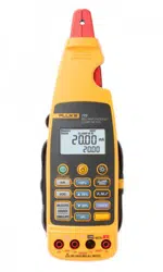
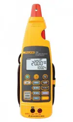
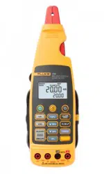
1. The 771 Milliamp Process Clamp Meter ............................................................... 5
2. Changing the Batteries ........................................................................................... 7
3. Display Test ........................................................................................................... 9
4. Accessing the Calibration Button........................................................................... 12
5. Phase Adjustment................................................................................................... 14
6. Replaceable Parts ................................................................................................... 16
1.888.610.7664 sales@GlobalTestSupply.com
Fluke-Direct.com

1
771
Milliamp Process Clamp Meter
Introduction
XW Warning
To avoid electric shock or personal injury, do not perform the
calibration verification tests or calibration procedures
described in this manual unless you are qualified to do so.
The information provided in this manual is for the use of
qualified personnel only.
This manual provides the complete verification and adjustment procedure for the
771 Milliamp Process Clamp Meter (referred to in this manual as the Meter).
The Meter allows closed-case calibration using reference sources. It measures the
reference signals, calculates the correction factors, and stores them in memory. The
instrument should be calibrated after repair, or if it fails a performance test.
The 771 Calibration Manual provides the following information:
• Precautions and safety information
• Specifications
• Basic maintenance
• Calibration verification procedure
• Replaceable parts and accessories
For complete operating instructions, refer to the 771 Instruction Sheet.
1.888.610.7664 sales@GlobalTestSupply.com
Fluke-Direct.com

771
Calibration Manual
2
Safety Information
In this manual, a Warning identifies conditions and actions that pose hazard(s) to the
user. A Caution identifies conditions and actions that may damage the test instrument.
The design and manufacture of the device conforms to the latest state of technology and
the safety standards specified in IEC 61010-1/ 2
nd edition. If used improperly, there is a
risk of damage to persons and property.
XWWarning
To avoid possible electric shock or personal injury, follow these
guidelines:
• Read this manual before use and follow all safety
instructions.
• Use the Meter only as specified in this manual; otherwise,
the Meter's safety features may be impaired.
• Before each use inspect Meter and cable for damage. Look
for cracks and missing portions of the clamp and cable. Do
not use if clamp is damaged.
• Use caution when working with voltages above 33 V rms
47 V peak or 70 V dc these voltages pose a shock hazard.
• Do not use to measure ac current.
• Do not use to measure dc mA in circuits carrying more
than 300 V CAT II.
• Avoid working alone so assistance can be rendered in an
emergency.
• Use extreme caution when working around bare
conductors or bus bars. Contact with the conductor could
result in electric shock.
• To avoid false readings that can lead to electrical shock
and injury, replace the batteries as soon as the low battery
indicator (B) appears.
• Adhere to local and national safety codes. Individual
protective equipment must be used to prevent shock and
arc blast injury where hazardous live conductors are
exposed.
1.888.610.7664 sales@GlobalTestSupply.com
Fluke-Direct.com
Milliamp Process Clamp Meter
Symbols
3
• When measuring, keep fingers behind the Tactile Barrier.
See Figure 1.
• Not for use with non-insulated conductors.
WCaution
To avoid damage to the Meter, do not open the Meter for
cleaning. Do not use solvents to clean it, and do not immerse it
in liquid.
Symbols
Table 1 explains the symbols that are used on the Meter or in this manual.
Table 1. Symbols
-
Do not apply around, or remove from HAZARDOUS LIVE conductors
W
Risk of danger. Important information. See Users Manual.
X
Risk of Electrical Shock
T
Equipment protected by double or reinforced insulation
M
Battery
B
Low Battery
P
Conforms to relevant European Union directives
F
DC (Direct Current)
~
Do not dispose of this product as unsorted municipal waste. Go to Fluke’s web site for
recycling information.
;
N10140
Conforms to relevant Australian standards
)
Conforms to relevant Canadian and US standards
CAT II
300 V
Equipment is designed to protect against transients in equipment in fixed-equipment
installations, such as distribution panels, feeders and short branch circuits, and lighting
systems in large buildings.
1.888.610.7664 sales@GlobalTestSupply.com
Fluke-Direct.com

771
Calibration Manual
4
Specifications
Current Ranges ±20.99 mA ±21.0 mA - ±99.9 mA
Resolution 0.01 mA 0.1 mA
Accuracy
20.99 mA range
99.9 mA range
0.2 % reading ±5 digits
1 % reading ±5 digits
Maximum Reading ±99.9 mA
Influence of Earth’s Field < 0.20 mA
Battery 2 AA 1.5 V Alkaline, IEC LR6
Working hours 45 hours
Size (H X W X L) 59 mm x 38 mm x 212 mm (2.32 in x 1.49 in x 8.34 in)
(with clamp nested)
Weight 260 g (9.17 oz) (Including battery)
Operating Temperature -10 to 50 °C
(14 to 122 °F)
Storage Temperature -25 to 70 °C
(-13 to 158 °F)
Operating Humidity < 90 % @ <30 °C (86 °F)
<75 % @ 30 to 50 °C (86 to 122 °F)
Operating Altitude 0 to 2000 m (1.24 miles)
Storage Altitude None
IP Rating IP 40
Vibration Requirements Random 2 g, 5 to 500 Hz
EMI, RFI, EMC Meets all applicable requirements in EN 61326-1
Temperature Coefficients 0.1x(specified accuracy)/°C
(< 18 °C or > 28 °C)
Measurement Category IEC 61010-1
61010-2-032
CAT II 300 V
CAT II Equipment is designed to protect against transients from
energy-consuming equipment supplied from the fixed installation,
such as TVs, PCs, portable tools, and other household appliances.
Agency Approvals
P, ), ;, FCC
N10140
1.888.610.7664 sales@GlobalTestSupply.com
Fluke-Direct.com
Milliamp Process Clamp Meter
Getting Acquainted with the Meter
5
Getting Acquainted with the Meter
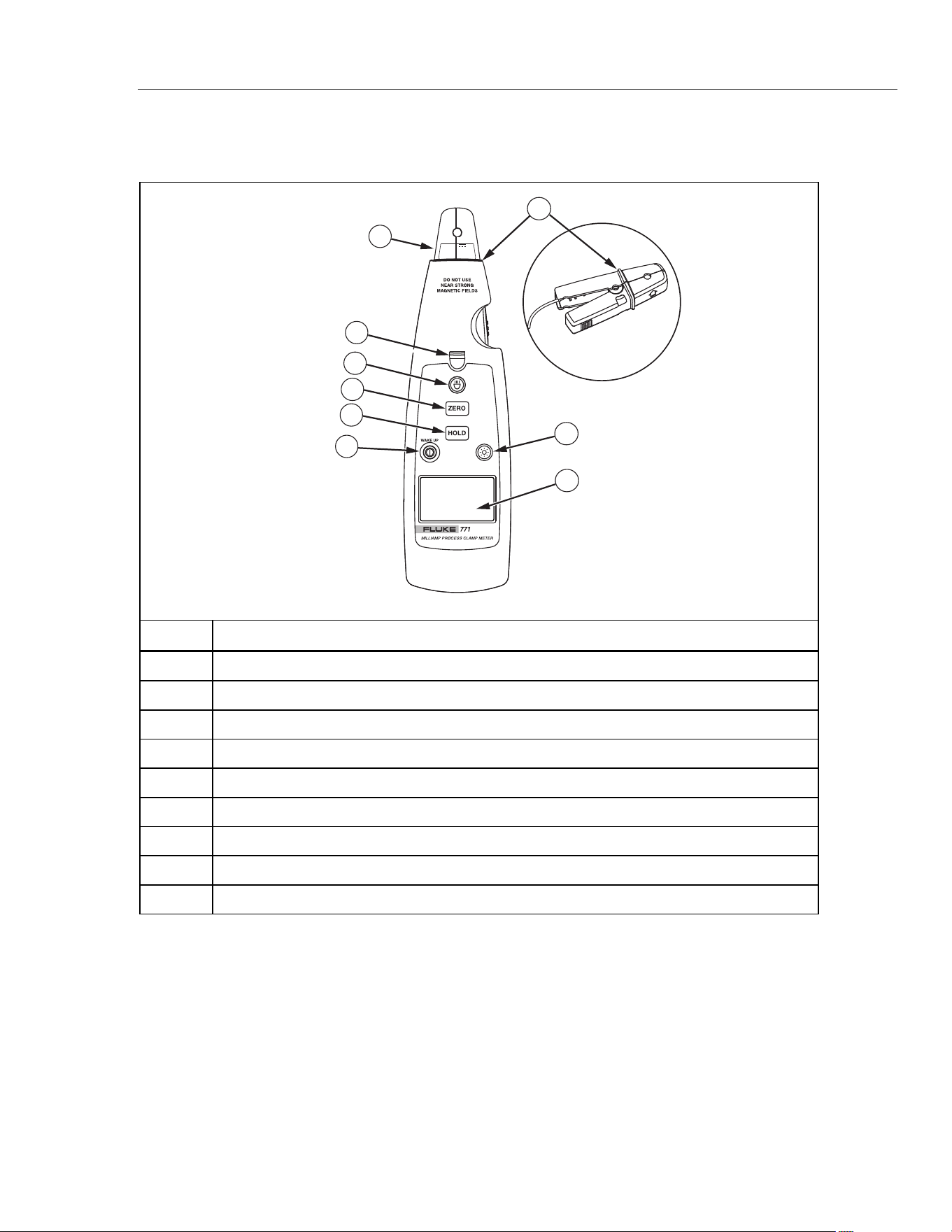
Figure 1 shows the Meter functions and features.
1
2
3
4
5
6
7
8
9
ege01a.eps
Number Description
A
Turns the Meter on and off. When the Meter is in sleep mode, press this button to wake it up.
B
Captures and holds the current reading
C
Removes interference and zeros the display
D
Measurement spotlight LED button
E
Measurement spotlight LED
F
Detachable clamp
G
Turns the backlight off and on
H
LCD
I
Tactile Barrier docked and un-docked
Figure 1. The 771 Milliamp Process Clamp Meter
1.888.610.7664 sales@GlobalTestSupply.com
Fluke-Direct.com

771
Calibration Manual
6
Maintenance
XWWarning
To avoid possible electric shock or personal injury, repairs or
servicing not covered in this manual should be performed only
by qualified personnel.
Cleaning the Meter
XWWarning
To avoid electrical shock, remove any input signals before
cleaning.
W Caution
To avoid damaging the Meter, do not use aromatic
hydrocarbons or chlorinated solvents for cleaning. These
solutions will react with the plastics used in the Meter.
Clean the instrument case with a damp cloth and mild detergent.
Battery Replacement
XWWarning
To avoid false readings, that could lead to possible electric
shock or personal injury, replace the battery as soon as the low
battery indicator (B) appears.
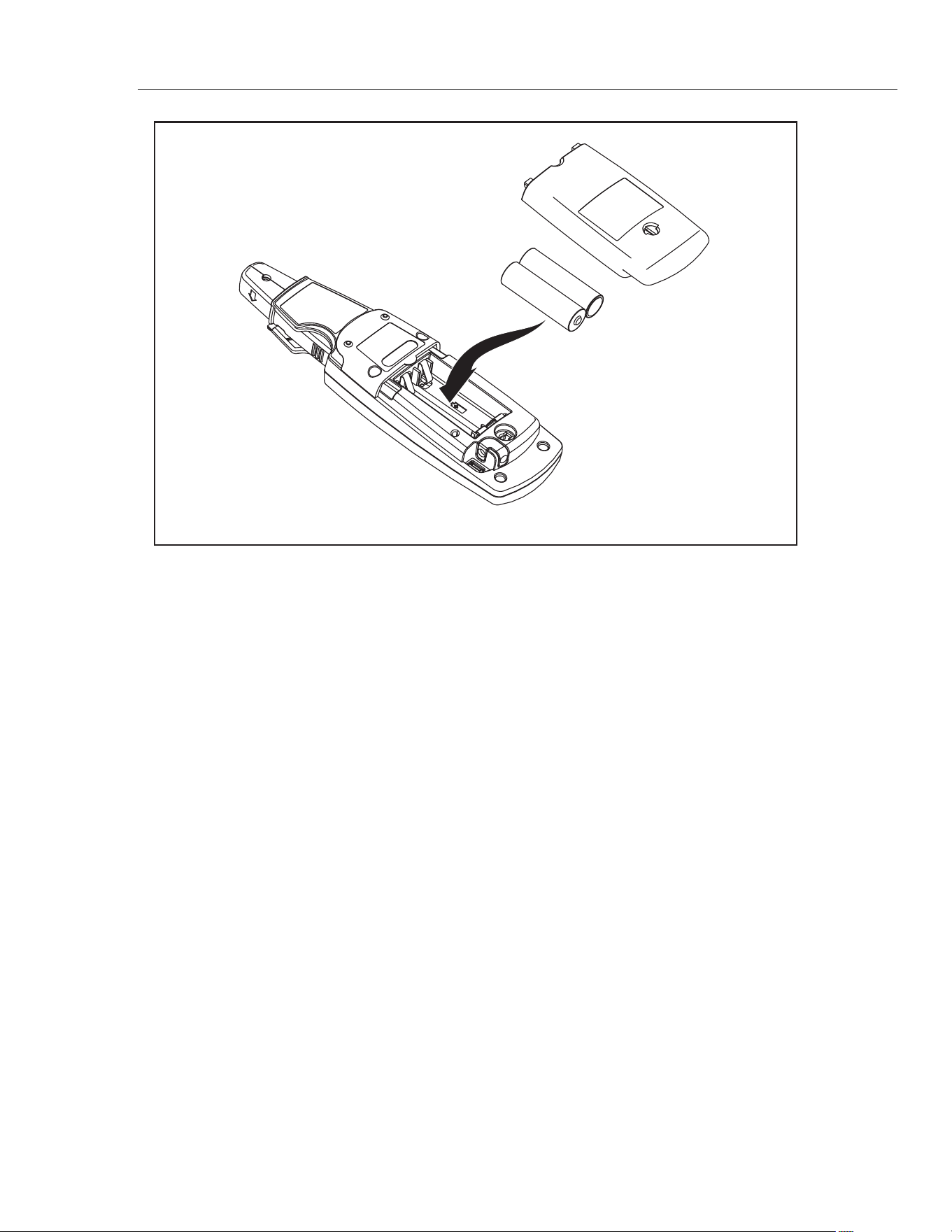
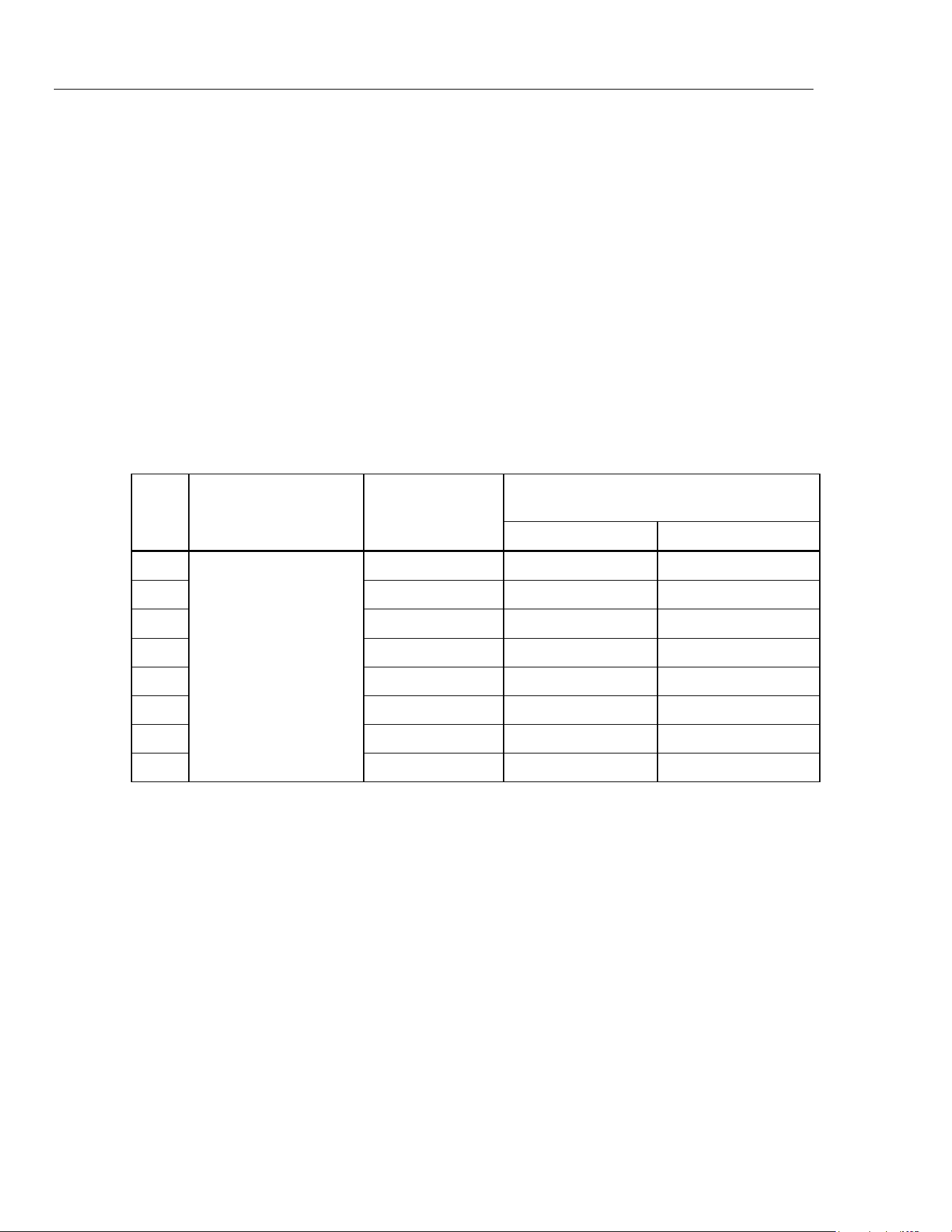
To replace the batteries, see Figure 2:
1. Turn the Meter off.
2. Use a flat head screwdriver to loosen the battery access door fastener, and remove the
door from the case bottom.
3. Remove the batteries.
4. Replace the batteries with two new AA batteries.
5. Reattach the battery access door to the case bottom and tighten the fastener.
1.888.610.7664 sales@GlobalTestSupply.com
Fluke-Direct.com
Milliamp Process Clamp Meter
Maintenance
7
ege02.eps
Figure 2. Changing the Batteries
1.888.610.7664 sales@GlobalTestSupply.com
Fluke-Direct.com

771
Calibration Manual
8
Performance Tests
XWWarning
To avoid electrical shock, personal injury, or fire:
• Do not perform the verification tests or calibration
adjustment described in this manual unless you are
qualified to do so.
• Repairs or servicing should be performed only by qualified
personnel.
The following tests are used to verify the functions of the Meter. If the Meter fails any of
the verification tests, repair is necessary. For service, see Contacting Fluke.
Required Equipment
Required equipment for the performance tests is listed in Table 2. If the recommended
models are not available, equipment with equivalent specifications may be used.
Table 2. Required Equipment
Equipment
Minimum Required
Characteristics
Recommended Model
Calibrator
DC Current Accuracy:
Range:
20.99 mA = 0.11 %
99.9 mA = 0.375 %
5520A or equivalent
1 loop insulated copper wire
Insulated 18 gauge, minimum, copper
wire, 6 inch diameter
Testing the Batteries
Prior to performing the following tests, check the batteries with a multimeter and replace
as necessary. See Battery Replacement.
1.888.610.7664 sales@GlobalTestSupply.com
Fluke-Direct.com
Milliamp Process Clamp Meter
Performance Tests
9
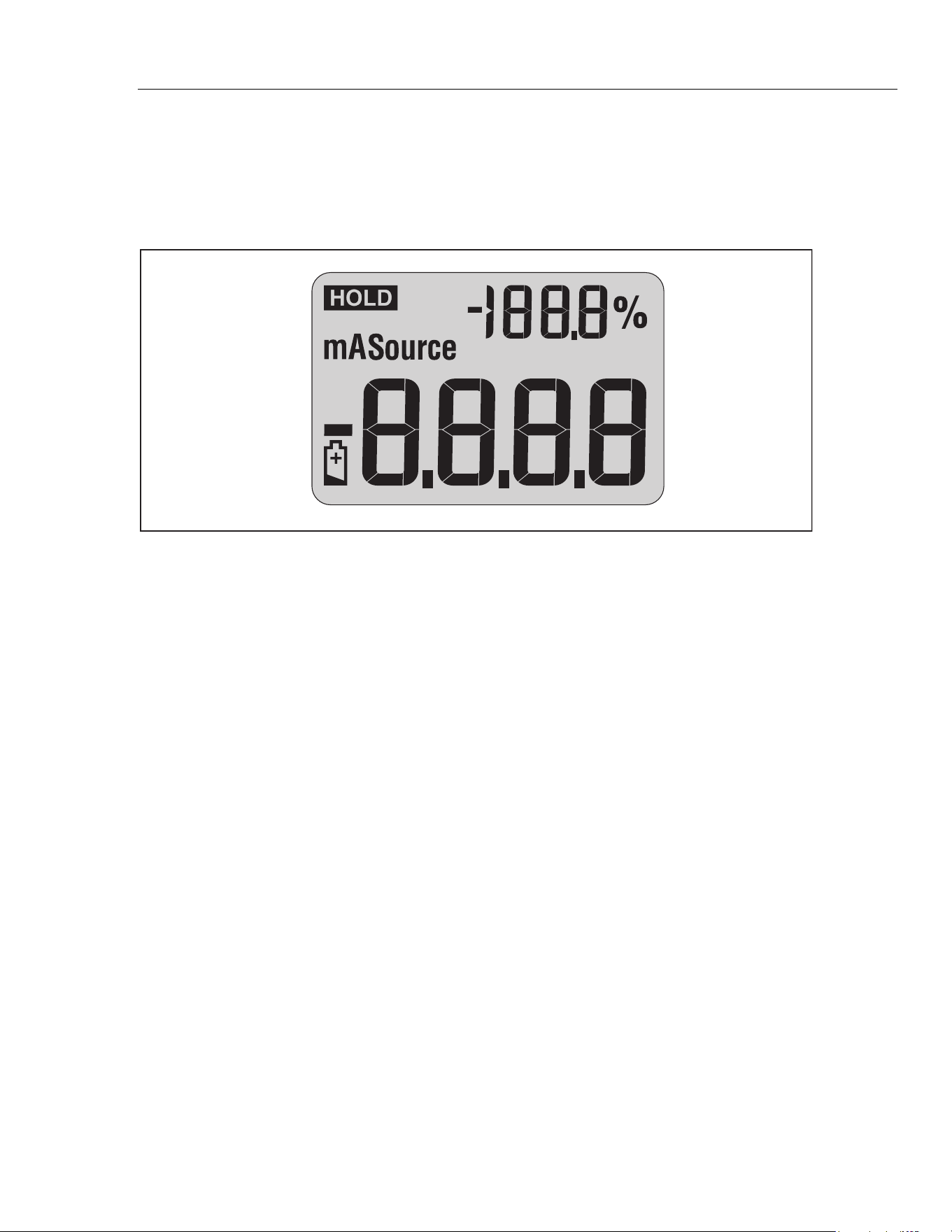
Testing the Display
1. Press and hold Awhile powering on the Meter.
2. Compare the Meter display to Figure 3.
3. Check all display segments for clarity and contrast.
fdp1.eps
Figure 3. Display Test
Display Hold Test
1. Power on the Meter and allow time for the normal operating display to appear.
2. Press H and observe that I appears on the display. I flashes at 3 to 4
second intervals.
Backlight Test
1. Power on the Meter and allow time for the normal operating display to come up.
2. Press C and observe that the backlight comes on.
Spotlight LED Test
1. Power on the Meter and allow time for the normal operating display to come up.
2. Press L and observe that the spotlight LED comes on.
Zero Test
1. Power on the Meter and allow time for the normal operating display to come up.
2. Press A. The main display momentarily reads 0.00, and the percentage scale
momentarily reads -25.0%.
Accuracy Tests
Accuracy specifications are valid for 1 year after calibration when measured at an
operation temperature of 18 °C to 28 °C. Allow the Meter to stabilize at room
temperature prior to performing the accuracy tests.
Table 3 lists the required performance test points for verifying Meter accuracy. A zero
adjustment must be performed prior to completing each performance test point.
1.888.610.7664 sales@GlobalTestSupply.com
Fluke-Direct.com
771
Calibration Manual
10
Perform the tests as follows:
1. Connect a single loop of 14 gauge insulated copper wire to the calibrator AUX output
terminals.
2. Clamp the Meter jaw around the wire with the jaw arrow pointing toward the
calibrator HI terminal.
3. Output 0 mA dc from the calibrator.
4. Press A on the Meter.
5. Set the calibrator output for the value in Step 1 of Table 3.
6. Compare the Meter displayed reading with the display reading limits in Table 3.
7. Complete steps 2-4 for each calibrator output setting in Table 3.
8. If the Meter fails to meet any of the Display Reading Limits, it requires calibration
adjustment, or repair. See Calibration Adjustment or Contacting Fluke.
Table 3. Accuracy Tests
Unit Under Test
Display Reading Limits
Step
Unit Under Test
Function
Calibrator
Output Setting
Lower Limit Upper Limit
1. 100 mA dc 98.5 101.5
2. -100 mA dc -100.7 -99.3
3. 20 mA dc 19.91 20.09
4. -20 mA dc -20.09 -19.91
5. 12 mA dc 11.93 12.07
6. -12 mA dc -12.07 -11.93
7. 4 mA dc 3.94 4.06
8.
mA dc
-4 mA dc -4.06 -3.94
1.888.610.7664 sales@GlobalTestSupply.com
Fluke-Direct.com

Milliamp Process Clamp Meter
Calibration Adjustment
11
Calibration Adjustment
Adjustment Subroutines
The Meter features closed-case calibration adjustment using a known reference source.
The Meter measures the applied reference source, calculates correction factors, and stores
the correction factors in nonvolatile memory.
There are four adjustment subroutines in the Meter adjustment procedure:
• Low Range (±20 mA)
• High range (±100 mA)
• Temperature
• Phase
Note
Temperature adjustment should always be performed prior to performing
the other adjustment routines. The phase adjustment routine is ONLY
required if the unit is repaired or the current clamp is replaced.
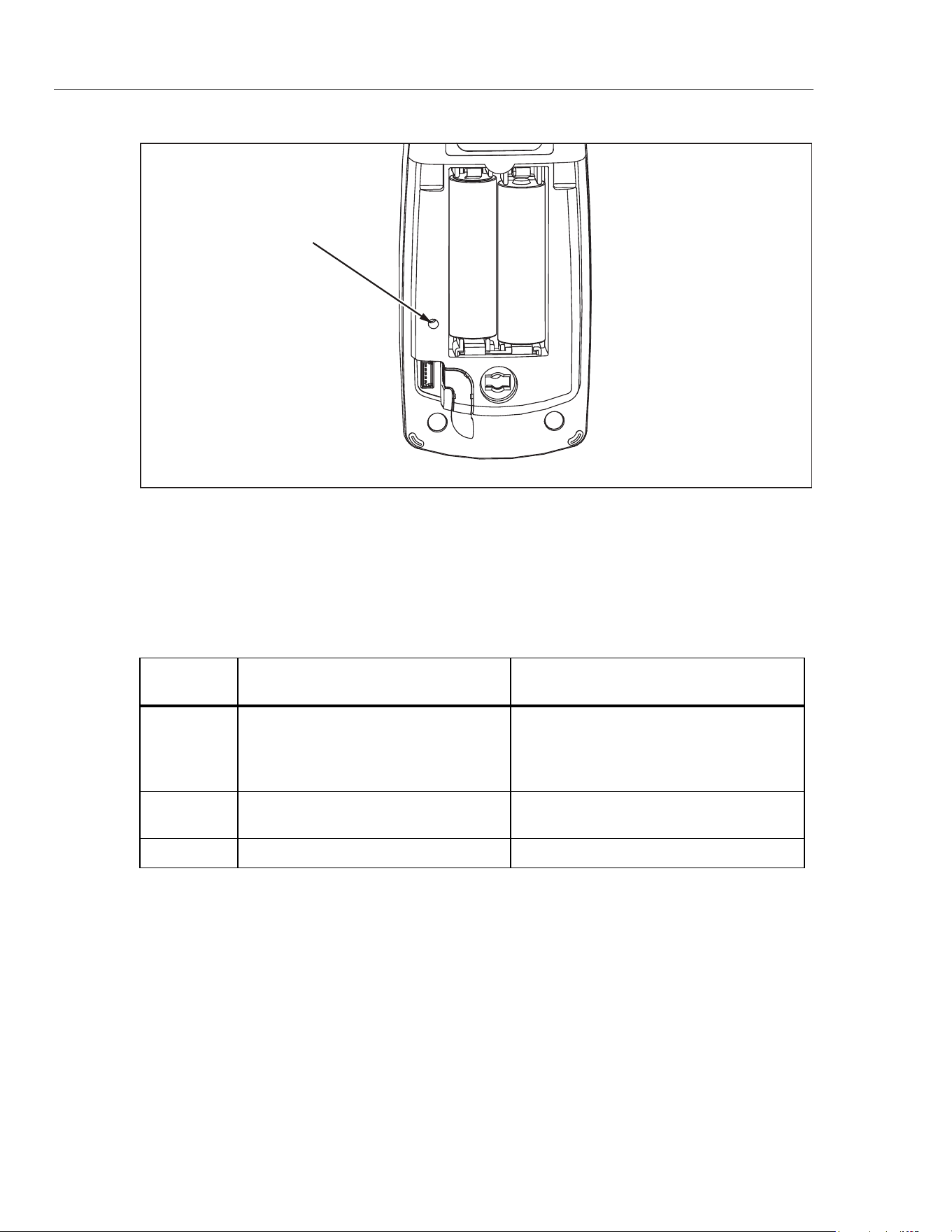
Front Panel Operation for Adjustment
Use a small probe to press the calibration button once to enter the Meter’s calibration
mode. The calibration button is usually covered by the factory calibration seal. A second
press of the button saves new calibration constants and exits calibration mode.
See Figure 4.
In calibration mode, C is used to select subroutines: low range, high range, temperature,
or phase. A short press of C (<1 second) will toggle between low and high range
subroutines. A long press (>1 second) will toggle between temperature and phase
subroutines.
• Pressing A is valid for all subroutines and normal operation. Pressing A will
zero the reading.
• In the low and high range subroutines, H and L are used to adjust the negative
and positive gain of the range.
• In the temperature subroutine, only H is valid for adjustment.
• In the phase subroutine, H and L are used to adjust the phase of two
sensor-excitation signals by increasing or decreasing a parameter.
1.888.610.7664 sales@GlobalTestSupply.com
Fluke-Direct.com
771
Calibration Manual
12
Calibration Button
fdp3.eps
Figure 4. Accessing the Calibration Button
Calibration Error Messages
Table 4 lists the calibration error messages that can be shown on the Meter display.
The suggested actions to eliminate messages are also listed.
Table 4. Error Messages
Error
Message
Cause of Error Suggested Action
CAL ERR1
The difference between the input level
and the zero point is less than the
minimal threshold when performing low
range and high range adjustments.
Check current loop and ensure correct
current is generated.
CAL ERR2
Calibration parameter checksum
failure.
Execute all adjustments including
temperature and phase.
CAL ERR3 Code checksum failure. The Meter requires repair.
Calibration Adjustment Procedure
Allow the Meter to stabilize to room temperature before beginning the calibration
adjustment.
To prepare for adjustment:
1. Remove the battery door and calibration seal.
2. Clamp the current loop in the current flow direction where required.
3. Turn the meter on and wait at least 10 seconds for warming up.
4. Press the hidden calibration button with a probe to enter calibration mode.
See Figure 4.
1.888.610.7664 sales@GlobalTestSupply.com
Fluke-Direct.com

Milliamp Process Clamp Meter
Calibration Adjustment
13
Temperature Adjustment Procedure
1. Press C for >1 second until t23 appears on the percentage display.
2. Wait at least 60 seconds for the internal temperature to balance.
3. Press H to adjust the temperature.
Low Range Adjustment Procedure
1. Clamp the Meter’s current clamp around an insulated 18 gauge, copper wire, with
6-inch diameter. Current flow should be in the direction of the arrow on the current
clamp.
2. Press C < 1 second until CAL 20 appears on percentage display.
3. Output 0 µA dc from the calibrator.
4. Wait at least 15 seconds for the Meter’s internal circuits to stabilize.
5. Press A on the Meter to zero the reading.
6. Output 20 mA dc from the calibrator.
7. Wait at least 15 seconds for the Meter’s internal circuits to stabilize.
8. Press L on the Meter to adjust the positive gain.
9. Output -20 mA dc from the calibrator.
10. Wait at least 15 seconds for the Meter’s internal circuits to stabilize.
11. Press H on the Meter to adjust the negative gain.
High Range Adjustment Procedure
1. Clamp the Meter’s current clamp around an insulated 18 gauge, copper wire, with
6-inch diameter. Current flow should be in the direction of the arrow on the current
clamp.
2. Press C < 1 second until CAL 100 appears on percentage display.
3. Output 0 µA dc from the calibrator.
4. Wait at least 15 seconds for the Meter’s internal circuits to stabilize.
5. Press A on the Meter to zero the reading.
6. Output 100 mA dc from the calibrator.
7. Wait at least 15 seconds for the Meter’s internal circuits to stabilize.
8. Press L on the Meter to adjust the positive gain.
9. Output -100
mA dc from the calibrator.
10. Wait at least 15 seconds for the Meter’s internal circuits to stabilize.
11. Press H on the Meter to adjust the negative gain.
Note
The following procedure is not required unless the Meter’s current clamp
has been replaced.
1.888.610.7664 sales@GlobalTestSupply.com
Fluke-Direct.com
771
Calibration Manual
14
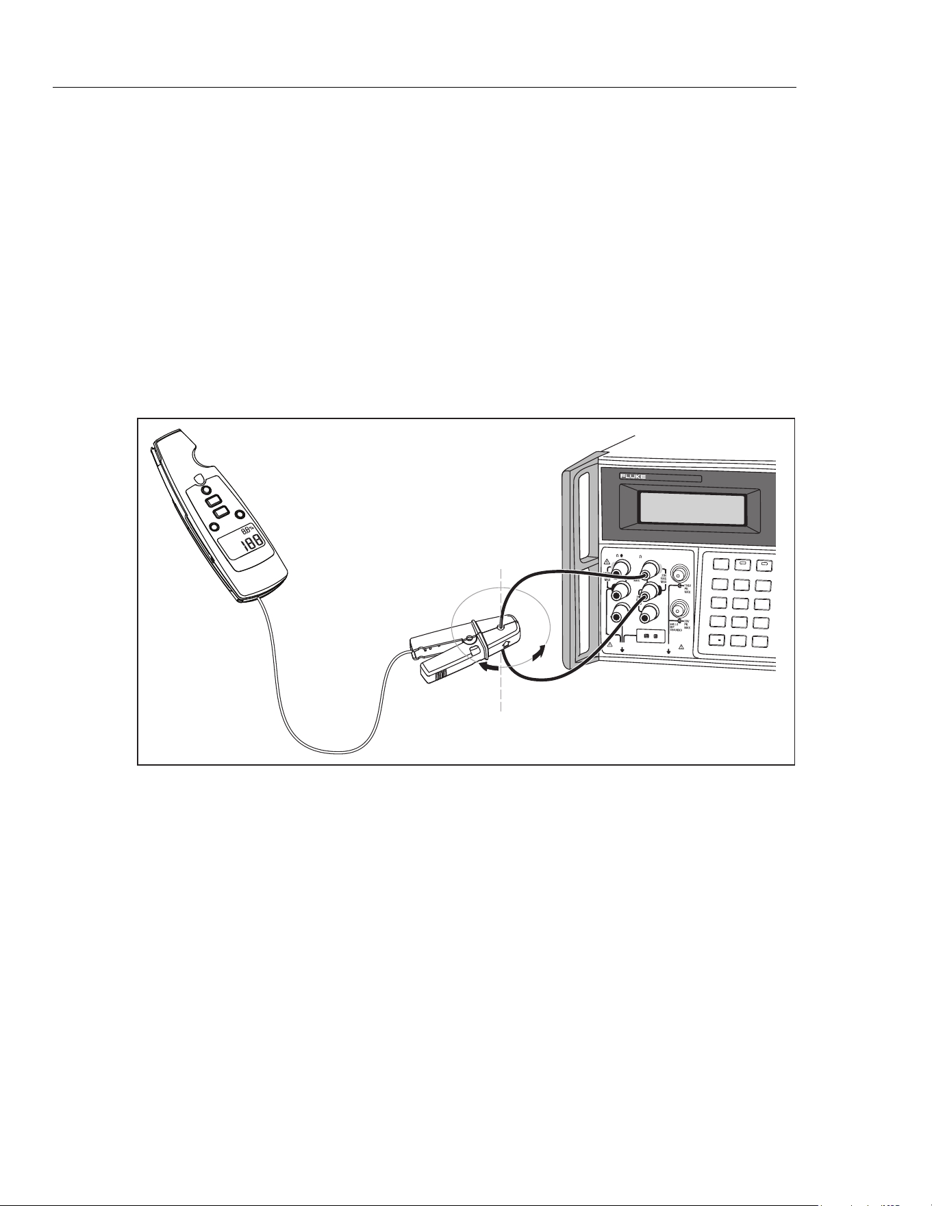
Phase Adjustment Procedure
1. Clamp the Meter’s current clamp around an insulated 18 gauge, copper wire, with
6-inch diameter. Current flow should be in the direction of the arrow on the current
clamp.
2. Press C >1 second until the percentage display indicates the Meter’s currently saved
phase value.
3. Output 0 µA dc from the calibrator.
4. Press A on the Meter to zero the reading.
5. Rotate the Meter’s clamp around the current loop conductor and record the minimum
and maximum values of the Meter’s display reading. See Figure 5.
6. Use Land H, to adjust the difference between the minimum and maximum value
recorded in Step 5, until the reading difference is less than 0.05 mA.
0
•
123
456
7 8 9
/
+
OPRSTBY EARTH
5520A
CALIBRATOR
HI
LO
TRIG
GUARD
TC
20A
NORMAL AUX
SCOPE
OUT
V, , ,
RTD
A, -SENSE,
AUX V
20V PK MAX
20V PK MAX
Rotate Meter clamp around
current loop conductor
fdp5.eps
Figure 5. Phase Adjustment
1.888.610.7664 sales@GlobalTestSupply.com
Fluke-Direct.com
Milliamp Process Clamp Meter
User Replaceable Parts
15
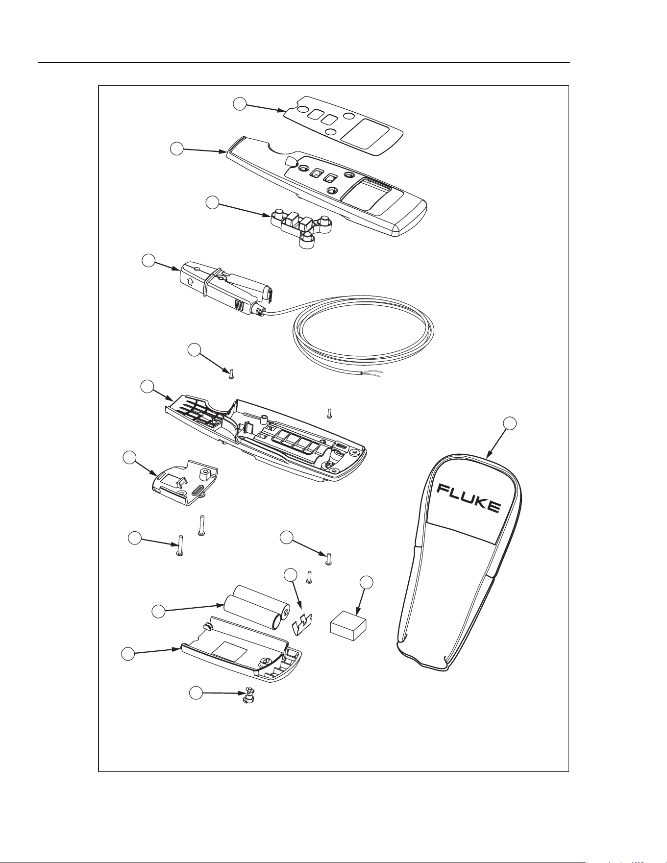
User Replaceable Parts
Table 5 and Figure 6 list all user replaceable parts.
Table 5. Replaceable Parts
Item ID Description P/N Qty
A Decal 2723063 1
B
Case top assembly
(does not include decal, order separately)
2720362 1
C Keypad 2723056 1
D Jaw assembly (Includes cable) 2722971 1
E
Screw,m2.2x0.8,8mm,pan,phillips,steel,zinc-black chromate, thread
form
1991287 2
F
Case, bottom
(does not include battery contact, order separately)
2720285 1
G Cable cleat 2720328 1
H Screw,4-14,.375,pan,phillips,steel, zinc-black chromate, thread form 2800097 2
I Battery contact, dual 666435 1
J
Screw,m3,13.5mm,pan,phillips,steel,zinc-black chromate, thread
form
2388412 2
K
Battery,primary,mno2-
zn,1.5v,2.24ah,15a,lr6,alkaline,aa,14x50mm,bulk
376756 2
L
Battery pad,urethane,adhesive-back,20.0mm l,20.0mm w,5.0mm
thk
2687457 1
M
Battery door
(does not include fastener, order separately)
2720304 1
N Access door fastener 948609 1
O LED housing 2720319 1
- Soft case, black/yellow 2726174 1
- 771 Instruction Sheet 2567301 1
1.888.610.7664 sales@GlobalTestSupply.com
Fluke-Direct.com
771
Calibration Manual
16
2
3
6
4
7
1
10
15
11
13
9
5
8
12
14
fdp4.eps
Figure 6. Replaceable Parts
1.888.610.7664 sales@GlobalTestSupply.com
Fluke-Direct.com