
October 2009
© 2009 Fluke Corporation. All rights reserved. Printed in USA. Specifications are subject to change without notice.
All product names are trademarks of their respective companies.
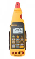
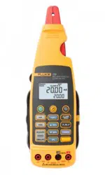
772/773
Milliamp Process Clamp Meter
Calibration Manual
1.888.610.7664 sales@GlobalTestSupply.com
Fluke-Direct.com

LIMITED WARRANTY AND LIMITATION OF LIABILITY
This Fluke product will be free from defects in material and workmanship for 3 years (one year for cable and
clamp) from the date of purchase. Parts, product repairs, and services are warranted for 90 days. This
warranty extends only to the original buyer or end-user customer of a Fluke authorized reseller, and does
not apply to fuses, disposable batteries, or to any product which, in Fluke's opinion, has been misused,
altered, neglected, contaminated, or damaged by accident or abnormal conditions of operation or handling.
Fluke warrants that software will operate substantially in accordance with its functional specifications for 90
days and that it has been properly recorded on non-defective media. Fluke does not warrant that software
will be error free or operate without interruption.
Fluke authorized resellers shall extend this warranty on new and unused products to end-user customers
only but have no authority to extend a greater or different warranty on behalf of Fluke. Warranty support is
available only if product is purchased through a Fluke authorized sales outlet or Buyer has paid the
applicable international price. Fluke reserves the right to invoice Buyer for importation costs of
repair/replacement parts when product purchased in one country is submitted for repair in another country.
Fluke's warranty obligation is limited, at Fluke's option, to refund of the purchase price, free of charge repair,
or replacement of a defective product which is returned to a Fluke authorized service center within the
warranty period.
To obtain warranty service, contact your nearest Fluke authorized service center to obtain return
authorization information, then send the product to that service center, with a description of the difficulty,
postage and insurance prepaid (FOB Destination). Fluke assumes no risk for damage in transit. Following
warranty repair, the product will be returned to Buyer, transportation prepaid (FOB Destination). If Fluke
determines that failure was caused by neglect, misuse, contamination, alteration, accident, or abnormal
condition of operation or handling, including overvoltage failures caused by use outside the product’s
specified rating, or normal wear and tear of mechanical components, Fluke will provide an estimate of repair
costs and obtain authorization before commencing the work. Following repair, the product will be returned to
the Buyer transportation prepaid and the Buyer will be billed for the repair and return transportation charges
(FOB Shipping Point).
THIS WARRANTY IS BUYER'S SOLE AND EXCLUSIVE REMEDY AND IS IN LIEU OF ALL OTHER
WARRANTIES, EXPRESS OR IMPLIED, INCLUDING BUT NOT LIMITED TO ANY IMPLIED WARRANTY
OF MERCHANTABILITY OR FITNESS FOR A PARTICULAR PURPOSE. FLUKE SHALL NOT BE LIABLE
FOR ANY SPECIAL, INDIRECT, INCIDENTAL OR CONSEQUENTIAL DAMAGES OR LOSSES,
INCLUDING LOSS OF DATA, ARISING FROM ANY CAUSE OR THEORY.
Since some countries or states do not allow limitation of the term of an implied warranty, or exclusion or
limitation of incidental or consequential damages, the limitations and exclusions of this warranty may not
apply to every buyer. If any provision of this Warranty is held invalid or unenforceable by a court or other
decision-maker of competent jurisdiction, such holding will not affect the validity or enforceability of any other
provision.
Fluke Corporation
P.O. Box 9090
Everett, WA 98206-9090
U.S.A.
Fluke Europe B.V.
P.O. Box 1186
5602 BD Eindhoven
The Netherlands
11/99
1.888.610.7664 sales@GlobalTestSupply.com
Fluke-Direct.com

i
Table of Contents
Title Page
Introduction........................................................................................................ 1
How to Contact Fluke ........................................................................................ 2
Safety Information ............................................................................................. 2
Symbols ............................................................................................................. 4
Specifications..................................................................................................... 4
Electrical Specifications ................................................................................ 4
DC Current Measurement ......................................................................... 4
DC Voltage Measurement (773) ............................................................... 4
DC Voltage Source (773).......................................................................... 5
mA DC IN/OUT (773) .............................................................................. 5
Scaled mA DC Current Output to mA Current Input from the Jaw (773) 5
General Specifications ....................................................................................... 5
Mechanical Specifications............................................................................. 5
Environmental Specifications........................................................................ 5
Standards and Agency Approval Specifications ........................................... 5
Other Specifications ...................................................................................... 5
Basic Maintenance............................................................................................. 6
How to Clean the Meter ................................................................................ 6
Battery Replacement ..................................................................................... 6
Performance Tests.............................................................................................. 7
Required Equipment...................................................................................... 7
How to Test the Batteries .............................................................................. 8
How to Test the Display ................................................................................ 8
Display Hold Test.......................................................................................... 8
Backlight Test................................................................................................ 8
Measurement Spotlight LED Test ................................................................. 8
Accuracy Tests................................................................................................... 9
mA DC Clamp Measure Accuracy Tests ...................................................... 9
mA DC Measure Accuracy Tests .................................................................. 9
Volts DC Measure Accuracy Tests ............................................................... 10
mA DC Source Accuracy Tests..................................................................... 10
Volts DC Source Accuracy Tests .................................................................. 10
Calibration Adjustment...................................................................................... 10
Calibration Error Messages ........................................................................... 12
mA DC Clamp Measure Adjustment Procedure ........................................... 13
mA DC Measure Adjustment Procedure ....................................................... 13
Volts DC Measure Adjustment Procedure .................................................... 13
mA DC Source Adjust Procedure.................................................................. 14
Volts DC Source Adjust Procedure (773 Only) ............................................ 14
Replaceable Parts............................................................................................... 15
1.888.610.7664 sales@GlobalTestSupply.com
Fluke-Direct.com

iii
List of Tables
Table Title Page
1. Symbols.................................................................................................................. 4
2. Required Equipment............................................................................................... 7
3. Calibration Functions ............................................................................................. 11
4. Calibration Adjustments......................................................................................... 12
5. Error Messages....................................................................................................... 12
6. Clamp Measure Adjustment Procedure.................................................................. 13
7. mA Measure Adjustment Procedure ...................................................................... 13
8. Volt Measure Adjustment Procedure ..................................................................... 13
9. mA Source Adjustment Procedure......................................................................... 14
10. Volt Source Adjustment Procedure........................................................................ 14
11. Replaceable Parts ................................................................................................... 15
1.888.610.7664 sales@GlobalTestSupply.com
Fluke-Direct.com

v
List of Figures
Figure Title Page
1. Tactile Barrier ........................................................................................................ 3
2. Battery Replacement .............................................................................................. 7
3. Display Test ........................................................................................................... 8
4. Accessing the Calibration Button........................................................................... 11
5. Replaceable Parts ................................................................................................... 16
1.888.610.7664 sales@GlobalTestSupply.com
Fluke-Direct.com

1
Introduction
XW Warning
To prevent electrical shock or personal injury, do not do the
calibration verification tests or calibration procedures in this
manual unless you are qualified.
The data in this manual is for qualified personnel only.
This manual tells you about verification and adjustment procedures for the 772/773
Milliamp Process Clamp Meter (referred to in this manual as the Meter). The Meter
features closed-case calibration to use with reference sources. It measures the reference
signals, calculates the correction factors, and keeps them in memory. Calibration
adjustment is required after a repair, or if the Meter fails a performance test.
This manual explains:
• Precautions and Safety Information
• Specifications
• Basic Maintenance
• Calibration/Verification Procedure
• Replaceable Parts and Accessories
For complete use instructions, refer to the 772/773 Instruction Sheet.
1.888.610.7664 sales@GlobalTestSupply.com
Fluke-Direct.com

772/773
Calibration Manual
2
Safety Information
In this manual, a Warning identifies conditions and procedures that are hazardous to the
user. A Caution identifies conditions and procedures that could cause Meter damage,
equipment under test damage, or permanent loss of data.
XWWarning
To prevent electrical shock or personal injury, and to prevent
damage to the Meter, follow these guidelines:
• Read this manual before use and follow all safety
instructions.
• Use the Meter only as this manual recommends. To use the
Meter incorrectly, compromises the safety features of the
Meter.
• Examine the case before you use the Meter. Look for
cracks, missing plastic or missing pieces of the clamp and
cable. Do not use if the clamp or Meter is damaged.
• Do not use on voltages >33 V ac rms, 47 V ac peak, or 70 V
dc.
• Do not use to measure ac current.
• Do not use to measure ac voltage.
• Do not work alone.
• Use maximum precautions when you work near bare
conductors or bus bars. If you touch the conductor, you
can receive an electrical shock.
• To prevent incorrect indications that can cause electrical
shock and injury, replace the batteries when the low-
battery indicator (B) appears.
• Follow local and national safety codes. You must use
protective equipment to prevent an electrical shock and arc
blast injury where hazardous live conductors are exposed.
1.888.610.7664 sales@GlobalTestSupply.com
Fluke-Direct.com
Milliamp Process Clamp Meter
Safety Information
3
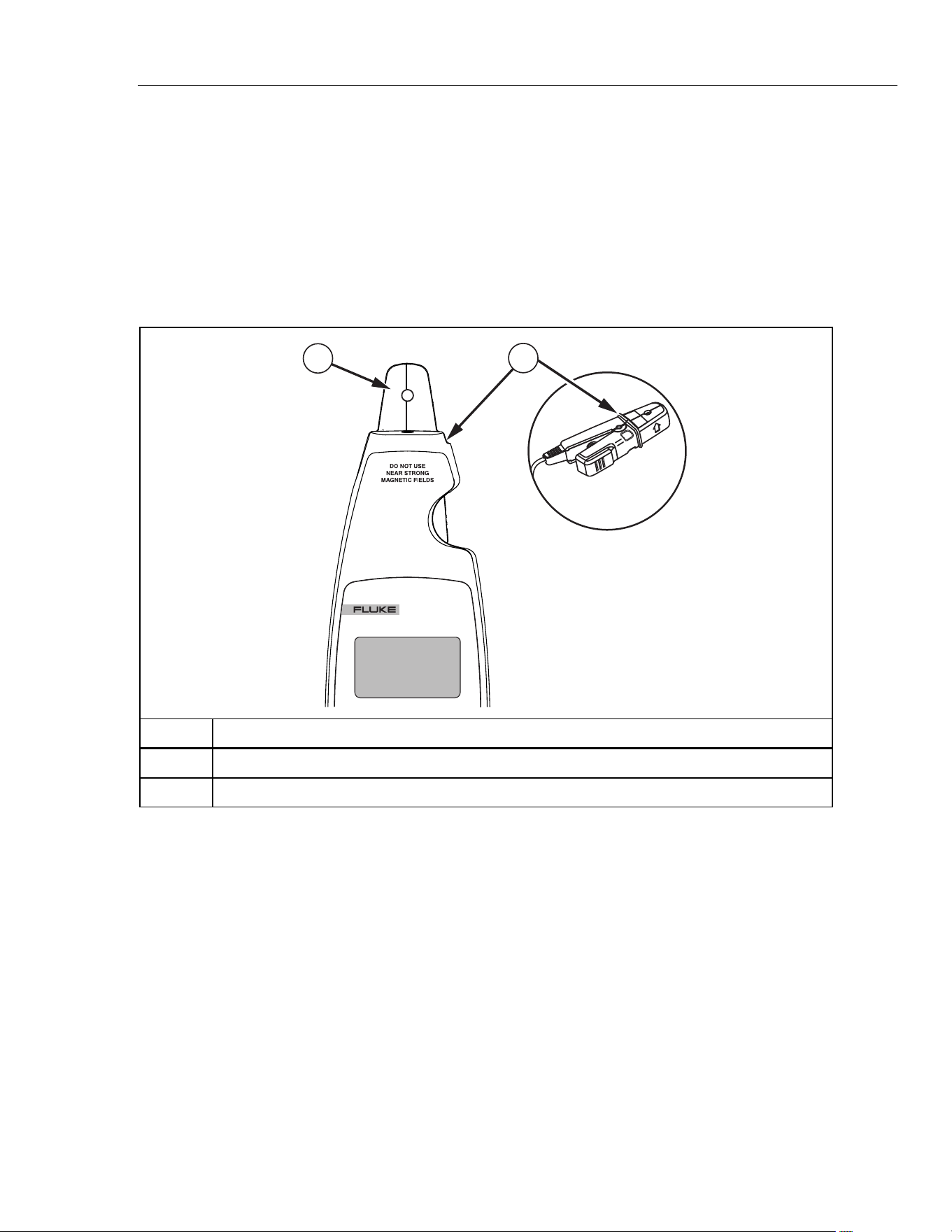
• When you measure, keep your fingers behind the Tactile
Barrier. See Figure 1.
• Do not use with a non-insulated conductor.
• Do not use near strong magnetic fields.
• Remove test leads before you open the case.
WCaution
To prevent damage to the Meter, do not open it. Do not use a
solvent to clean the Meter, and do not put the Meter in water.
773
MILLIAMP PROCESS
CLAMP METER
1
2
gep06.eps
Number Description
A Detachable clamp
B Tactile Barrier docked and un-docked.
Figure 1. Tactile Barrier
1.888.610.7664 sales@GlobalTestSupply.com
Fluke-Direct.com

772/773
Calibration Manual
4
Symbols
Table 1 refers to the symbols that are on the Meter or in this manual.
Table 1. Symbols
- Do not apply around, or remove from HAZARDOUS LIVE conductors.
W Dangerous. Important data. See Users Manual.
X Risk of Electrical Shock.
T Equipment protected by double or reinforced insulation.
M Battery
B Low Battery
P Confirms with relevant European Union directives.
F DC (Direct Current)
~
Do not dispose of this the product as unsorted municipal waste. Go to Fluke’s web site for
recycling data.
; Conforms to relevant Australian standards.
) Conforms to relevant Canadian and US standards.
Specifications
Electrical Specifications
DC Current Measurement
With Jaw
Ranges ......................................0-20.99 mA; 21-100 mA
Resolution.................................. 0.01 mA; 0.1 mA
Accuracy....................................0.2 % + 5 counts; 1 % + 5 counts
In Circuit
Range........................................ 0-24 mA
Resolution.................................. 0.01 mA
Accuracy....................................0.2 % + 2 counts
Current Source
Range........................................ 0-24 mA
Resolution.................................. 0.01 mA
Accuracy....................................0.2 % + 2 counts
mA Drive.................................... 24 mA into 1000 Ω
Current Simulate
Range........................................ 0-24 mA
Resolution.................................. 0.01 mA
Accuracy....................................0.2 % + 2 counts
Maximum Voltage...................... 50 V
DC Voltage Measurement (773)
Range........................................ 0-30 V
Resolution.................................. 0.01 V
Accuracy....................................0.2 % + 2 counts
1.888.610.7664 sales@GlobalTestSupply.com
Fluke-Direct.com

Milliamp Process Clamp Meter
General Specifications
5
DC Voltage Source (773)
Range........................................ 0-10 V
Resolution.................................. 0.01 V
Accuracy....................................0.2 % + 2 counts
mA Drive.................................... 2 mA max all conditions
mA DC IN/OUT (773)
Sourcing range .......................... 0-24 mA
Sourcing resolution.................... 0.01 mA
Sourcing accuracy ..................... 0.2 % + 2 counts
Measurement range ..................0-24 mA
Measurement resolution 0.01 mA
Measurement accuracy ............. 1 % FS
Scaled mA DC Current Output to mA Current Input from the Jaw (773)
Range........................................ 0-24 mA
Resolution.................................. 0.01 mA
Accuracy....................................1 % FS
General Specifications
Response speed........................... 2 times per second
DC Loop Power ............................ 24 V
Influence of Earth’s Field .............. < 0.20 mA
Batteries ....................................... 4 1.5 V, Alkaline, IEC LR6
Working hours ..............................12 hours @ 12 mA sourced into 500 Ω
Mechanical Specifications
Size (H X W X L) ......................... 43.7 mm x 70 mm x 246.2 mm
Weight .......................................... 410 g
Environmental Specifications
Operating Temperature .................. -10 ~ 50 °C
Storage Temperature...................... -25 ~ 60 °C
Operating Humidity......................... <90 % RH @ <30 °C ;<75 % RH @ 30 ~ 50 °C
Operating Altitude........................... 0 ~ 2000 m
IP Rating......................................... IP 40
Vibration Requirements .................. Random 2 g, 5 to 500 Hz
Drop Test Requirements............... 1 meter drop test (except the jaw)
EMI, RFI, EMC ............................. Meets all applicable requirements in EN61326-1
Note: For current measurement w/jaw, add 1 mA to specification for
EMC field strengths of 1 V/m up to 3 V/m.
Temperature Coefficients ............... 0.1(/ °C X Specified accuracy for Temperature < 18 °C or > 28 °C)
Standards and Agency Approval Specifications
All products certified to the following:
EN / IEC 61010-1, EN / IEC 61010-2-032
Agency Approvals:
P, ), ;
Other Specifications
Power Requirements ...... .......................................... Four AA batteries, Alkaline, IEC LR6
Automatic Time-out (Power) ...................................... After 15 minutes ±1 minutes
Automatic Time-out (Backlight).................................. After 2 minutes ±10 seconds
Automatic Time-out (Measurement Spotlight) ........... After 2 minutes ±10 seconds
1.888.610.7664 sales@GlobalTestSupply.com
Fluke-Direct.com

772/773
Calibration Manual
6
Basic Maintenance
XWWarning
To prevent electrical shock or personal injury, repairs or
servicing not included in this manual must be done only by
qualified personnel.
How to Clean the Meter
XWWarning
To prevent electrical shock or personal injury, remove test
leads before you clean the Meter.
W Caution
To prevent damage to the Meter, do not use aromatic
hydrocarbons or chlorinated solvents when you clean the
Meter. These solutions react with the plastics used in the Meter.
Clean the instrument case with a damp cloth and mild detergent.
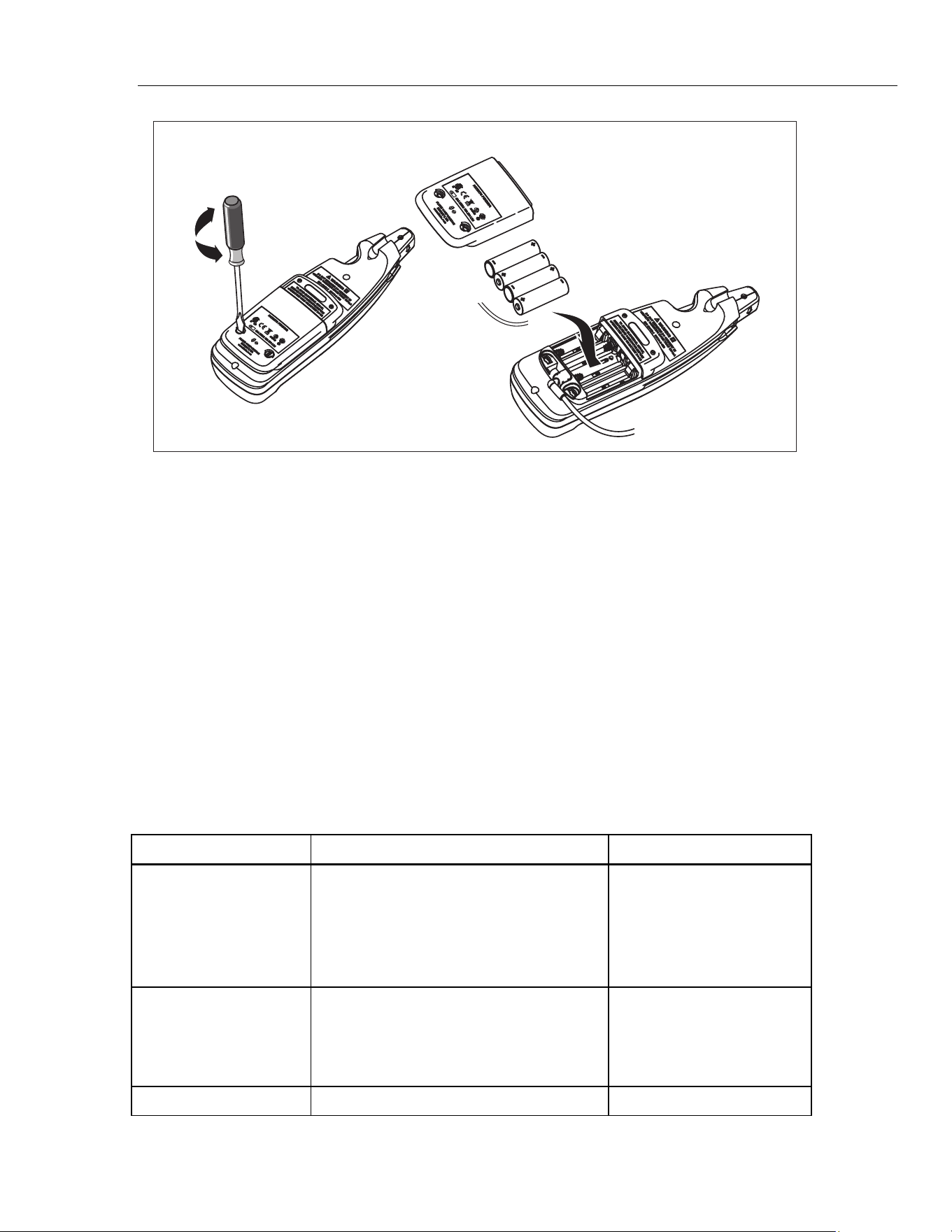
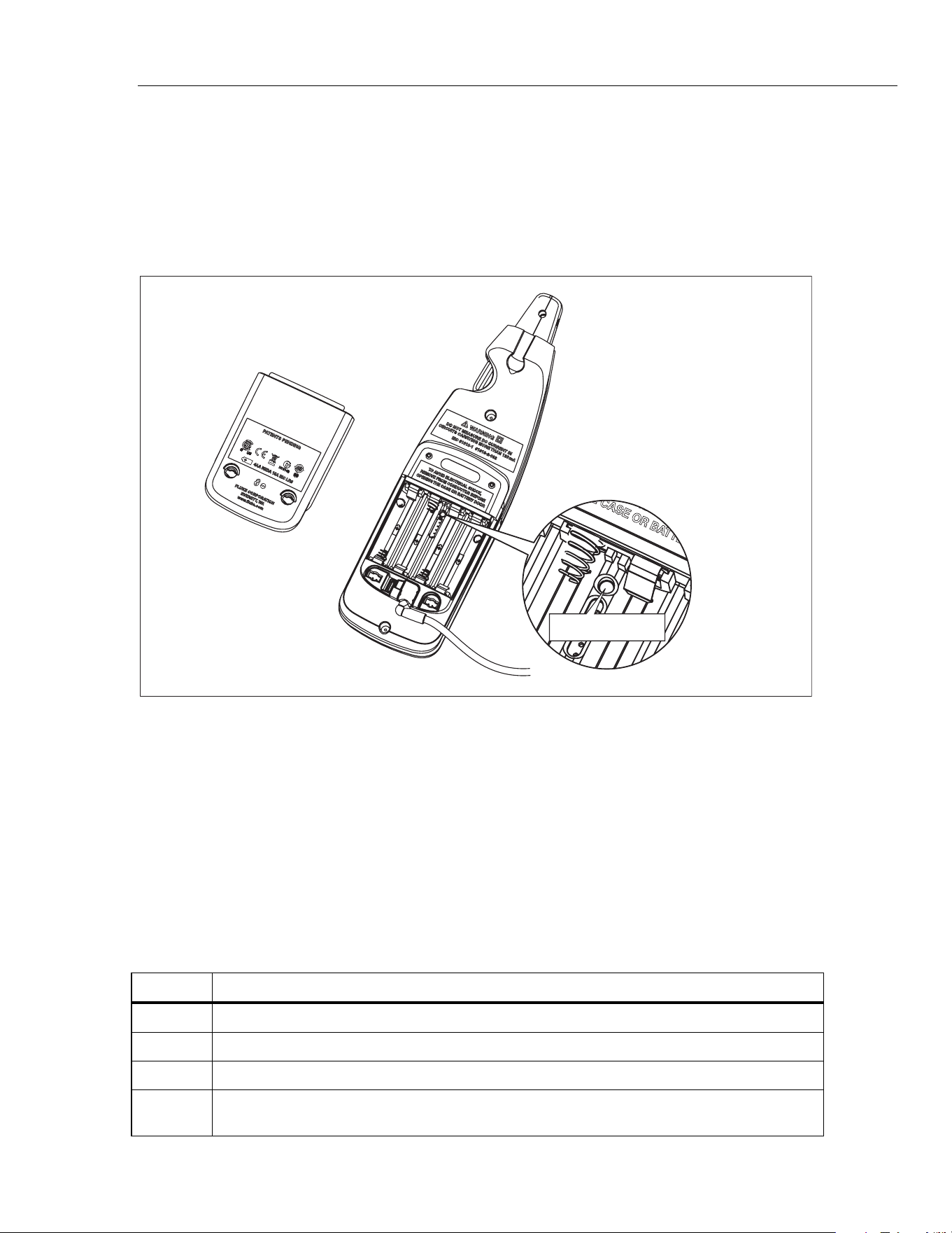
Battery Replacement
XWWarning
To prevent incorrect Meter indications that could cause
possible electrical shock or personal injury, replace the
batteries when the low battery indicator (B) appears.
To prevent electrical shock, remove test leads before changing
the batteries.
To replace the batteries, see Figure 2:
1. Turn the Meter off.
2. Use a flat-head screwdriver to loosen the battery compartment door screws, and
remove the door from the case bottom.
3. Remove the batteries.
4. Replace the batteries with four new AA batteries.
5. Reattach the battery compartment door to the case bottom and tighten the screws.
1.888.610.7664 sales@GlobalTestSupply.com
Fluke-Direct.com
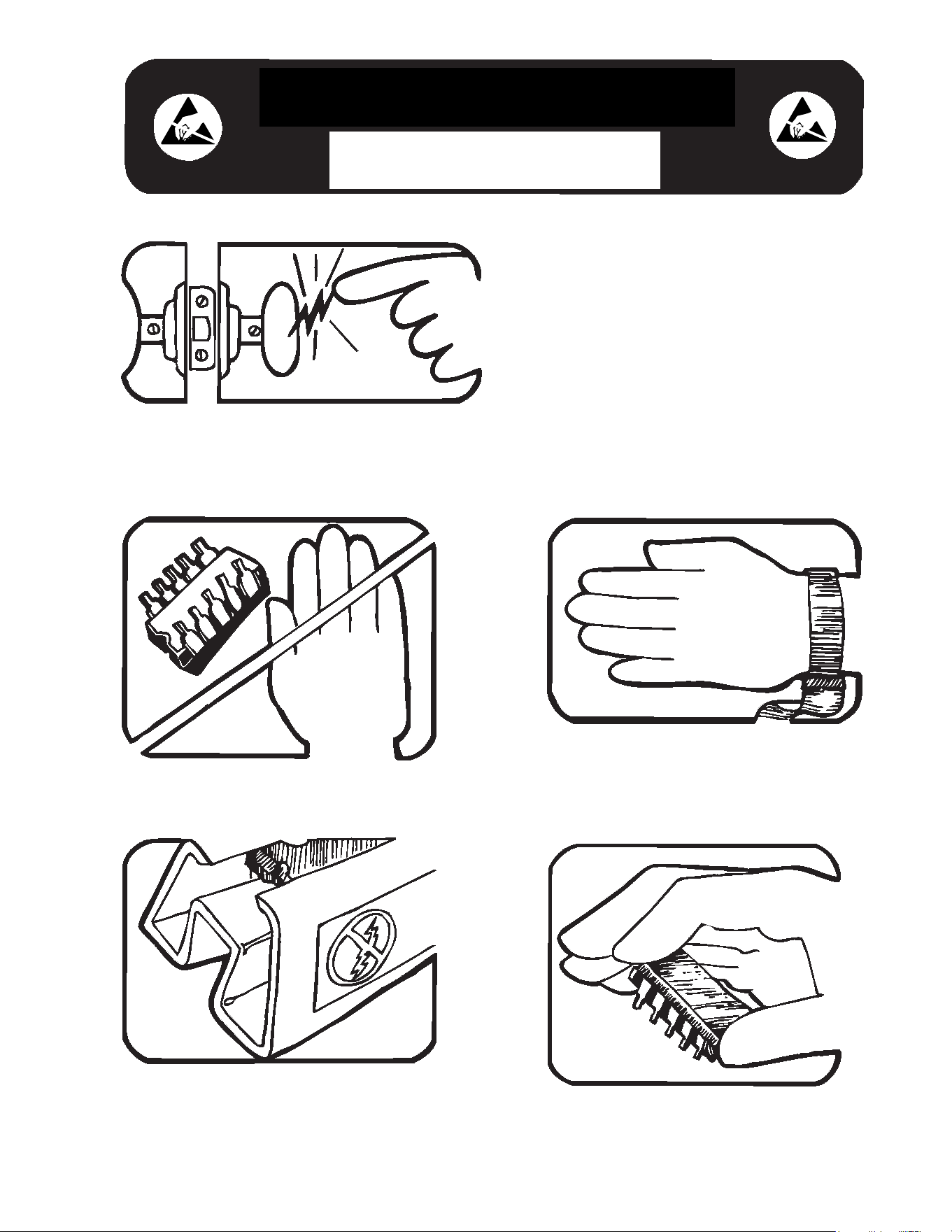
Some semiconductors and custom IC's can be
damaged by electrostatic discharge during
handling. This notice explains how you can
minimize the chances of destroying such devices
by:
1. Knowing that there is a problem.
2. Learning the guidelines for handling them.
3. Using the procedures, packaging, and
bench techniques that are recommended.
The following practices should be followed to minimize damage to S.S. (static sensitive) devices.
1. MINIMIZE HANDLING
2. KEEP PARTS IN ORIGINAL CONTAINERS
UNTIL READY FOR USE.
3. DISCHARGE PERSONAL STATIC BEFORE
HANDLING DEVICES. USE A HIGH RESIS-
TANCE GROUNDING WRIST STRAP.
4. HANDLE S.S. DEVICES BY THE BODY.
static awareness
A Message From
Fluke Corporation
1.888.610.7664 sales@GlobalTestSupply.com
Fluke-Direct.com
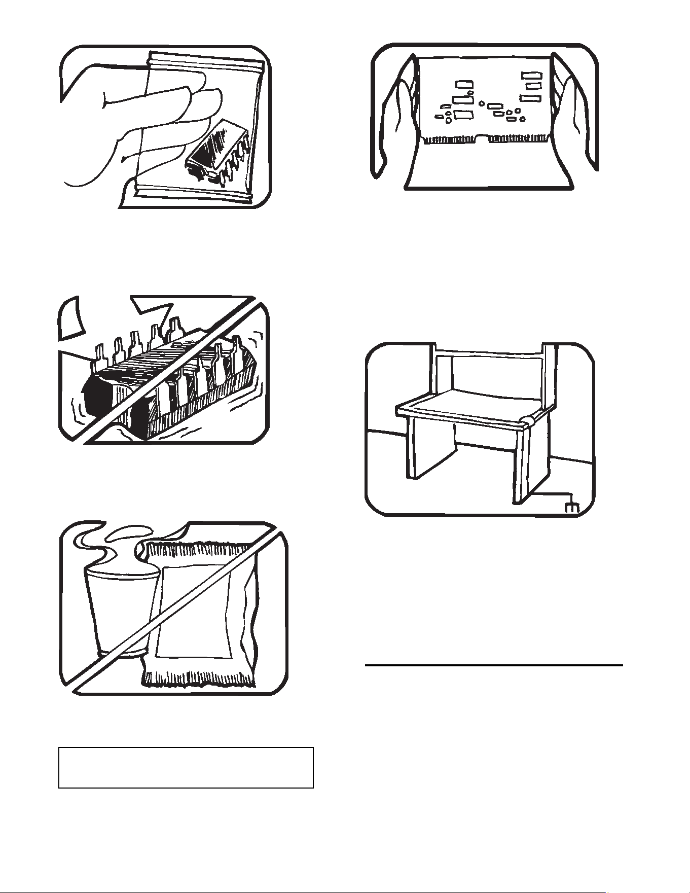
5. USE STATIC SHIELDING CONTAINERS FOR
HANDLING AND TRANSPORT.
6. DO NOT SLIDE S.S. DEVICES OVER
ANY SURFACE.
7. AVOID PLASTIC,VINYL AND STYROFOAM
IN WORK AREA.
8. WHEN REMOVING PLUG-IN ASSEMBLIES
HANDLE ONLY BY NON-CONDUCTIVE
EDGES AND NEVER TOUCH OPEN EDGE
CONNECTOR EXCEPT AT STATIC-FREE
WORK STATION. PLACING SHORTING
STRIPS ON EDGE CONNECTOR HELPS
PROTECT INSTALLED S.S. DEVICES.
9. HANDLE S.S. DEVICES ONLY AT A
STATIC-FREE WORK STATION.
10. ONLY ANTI-STATIC TYPE SOLDER-
SUCKERS SHOULD BE USED.
11. ONLY GROUNDED-TIP SOLDERING
IRONS SHOULD BE USED.
PORTIONS REPRINTED
WITH PERMISSION FROM TEKTRONIX INC.
AND GERNER DYNAMICS, POMONA DIV.
Dow Chemical
1.888.610.7664 sales@GlobalTestSupply.com
Fluke-Direct.com
Milliamp Process Clamp Meter
Performance Tests
7
gep02.eps
Figure 2. Battery Replacement
Performance Tests
XWWarning
To prevent electrical shock, personal injury, or fire:
• Repairs or Meter servicing must be done only by qualified
personnel.
• Do not do the verification tests or calibration adjustment in
this manual unless qualified.
The tests that follow verify the functions of the Meter. If the Meter fails the verification
tests, repair is necessary. For Meter servicing, see “How to Contact Fluke”.
Required Equipment
Required equipment for the performance tests is in Table 2. If the recommended models
are not available, equipment with equivalent specifications can be used.
Table 2. Required Equipment
Equipment Minimum Required Characteristics Recommended Model
Calibrator DC milliamps:
0-24.00 mA = ±0.073 %
24.0-100.0 mA = ±0.375 %
DC Volts:
0-30.00 V = ±0.267 %
Fluke 55xxA
DMM DC Current:
0-24.00 mA = ±0.375 %
DC Volts:
0-10 V = ±0.1 %
Fluke 88xxA
Lab Supply 6 Vdc ±-0.5 V -
1.888.610.7664 sales@GlobalTestSupply.com
Fluke-Direct.com
772/773
Calibration Manual
8
How to Test the Batteries
Prior to performing the following tests, check the batteries with a multimeter and replace
as necessary. See “Battery Replacement”.
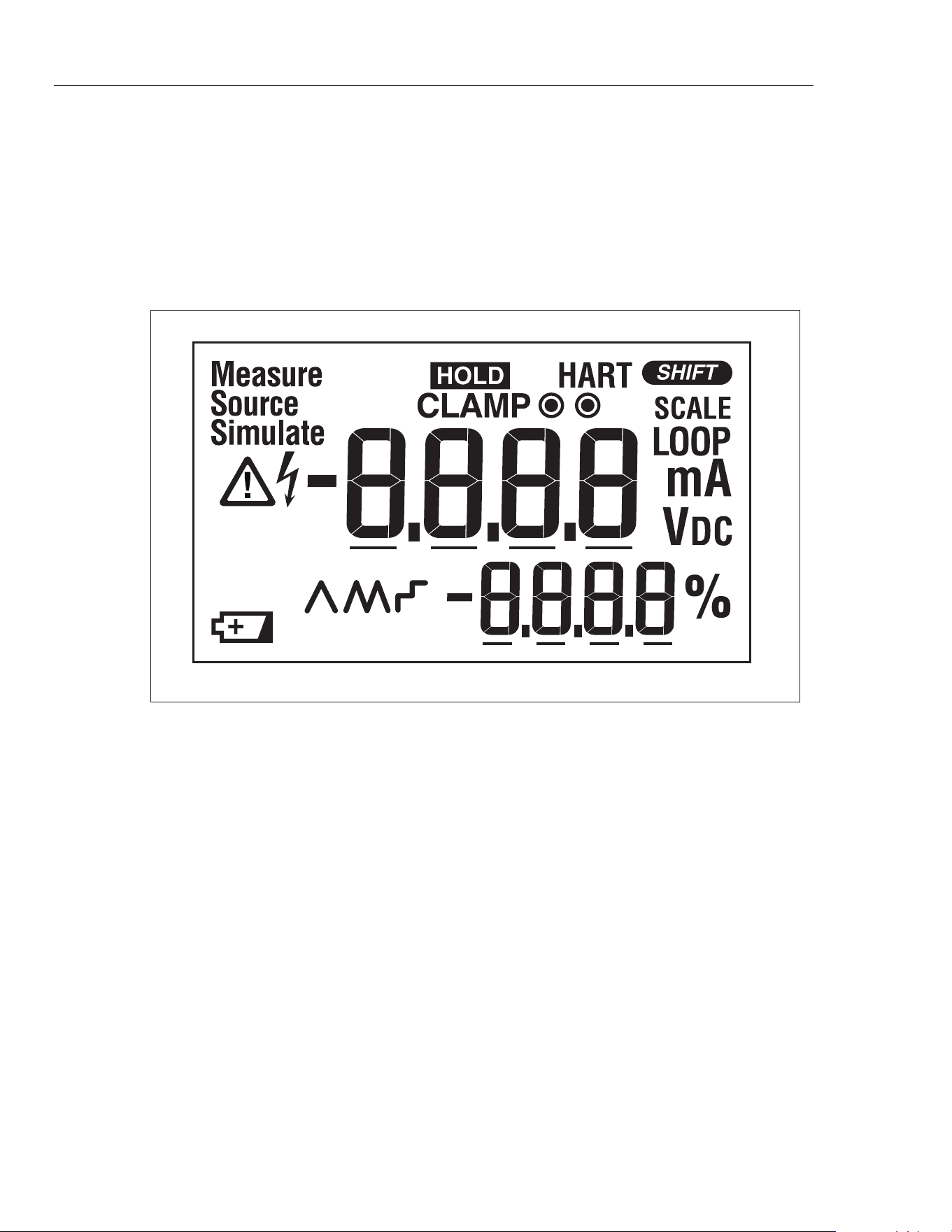
How to Test the Display
1. Push and hold H while powering on the Meter.
2. Compare the Meter display to Figure 3.
3. Examine all display segments for clarity and contrast.
MAX
gep07.eps
Figure 3. Display Test
Display Hold Test
XW Warning
Changes to the input signal will not register on the Meter
display when in Display Hold Mode. To prevent electrical shock
or personal injury, you must be aware of what mode the Meter
is in.
Push H to activate Display Hold mode. The display shows I and the display
freezes. Push H a second time to exit and resume normal operation.
Backlight Test
Push Q to turn the backlight on and off. To extend battery life, the backlight
automatically stops after 2 minutes.
Measurement Spotlight LED Test
Push A to activate the Measurement Spotlight LED. To extend battery life, the light
automatically stops after 2 minutes.
1.888.610.7664 sales@GlobalTestSupply.com
Fluke-Direct.com
Milliamp Process Clamp Meter
Accuracy Tests
9
Accuracy Tests
Accuracy specifications are valid for 1 year after calibration adjustment when measured
at an operation temperature of 18 °C to 28 °C. Allow the Meter to stabilize at room
temperature prior to performing the accuracy tests.
The following tables list the required performance test points for verifying Meter
accuracy. Zero the Meter prior to completing each measurement point.
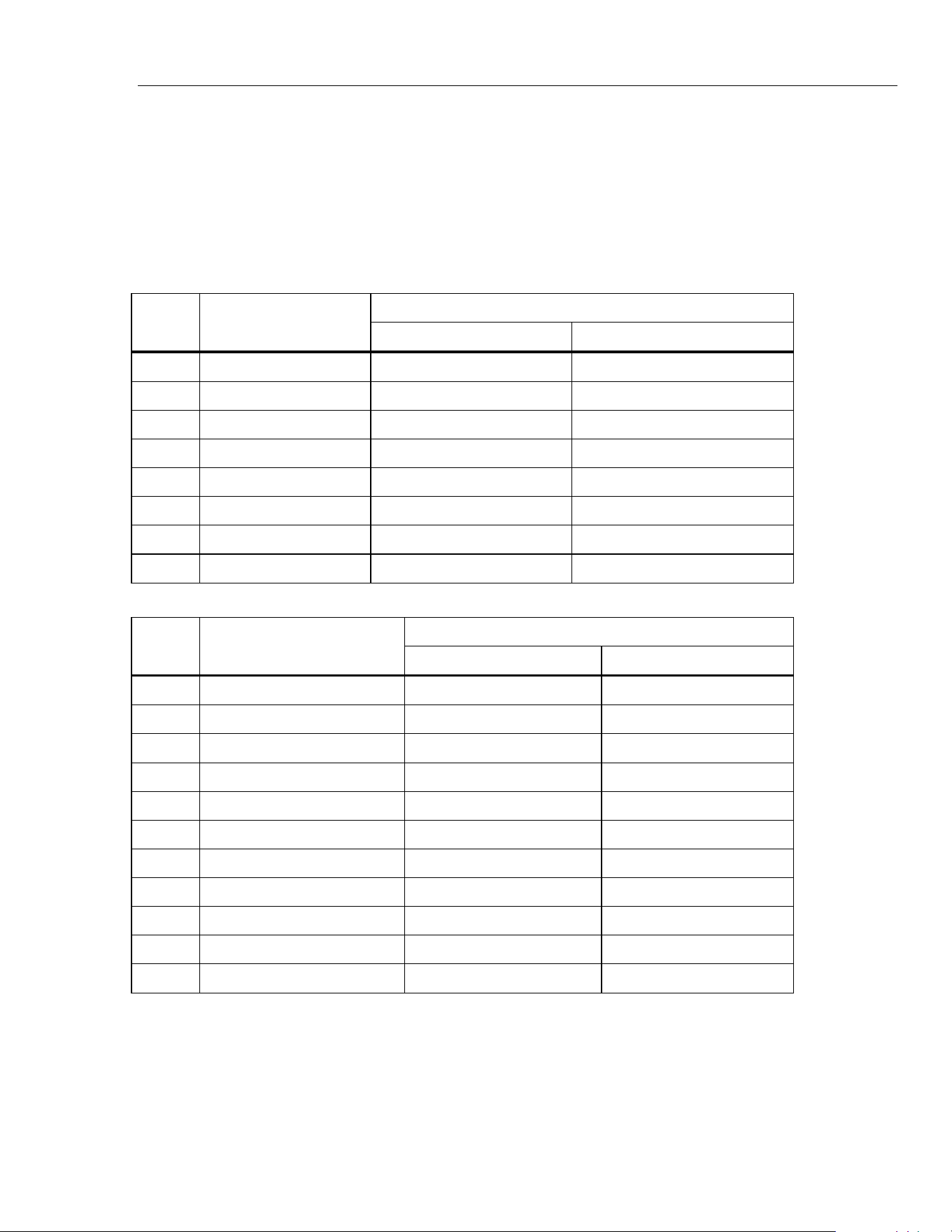
mA DC Clamp Measure Accuracy Tests
UUT Meter Reading Limit
Step Calibrator Output
Low High
1 4.00 mA 3.94 mA 4.06 mA
2 -4.00 mA -4.06 mA -3.94 mA
3 12.00 mA 11.03 mA 12.07 mA
4 -12.00 mA -12.07 mA -11.03 mA
5 20.00 mA 19.01 mA 20.09 mA
6 -20.00 mA -20.09 mA -10.01 mA
7 100.0 mA 98.5 mA 101.5 mA
8 -100.0 mA -101.5 mA -98.5 mA
mA DC Measure Accuracy Tests
UUT Meter reading limit
Step Calibrator Output
Low High
1 0.00 mA -0.02 mA 0.02 mA
2 4.00 mA 3.97 mA 4.03 mA
3 -4.00 mA -4.03 mA -3.97 mA
4 8.00 mA 7.96 mA 8.04 mA
5 -8.00 mA -8.04 mA -7.96 mA
6 12.00 mA 11.96 mA 12.04 mA
7 -12.00 mA -12.04 mA -11.96 mA
8 20.00 mA 19.94 mA 20.06 mA
9 -20.00 mA -20.06 mA -19.94 mA
10 24.00 mA 23.93 mA 24.07 mA
11 -24.00 mA -24.07 mA -23.93 mA
1.888.610.7664 sales@GlobalTestSupply.com
Fluke-Direct.com
772/773
Calibration Manual
10
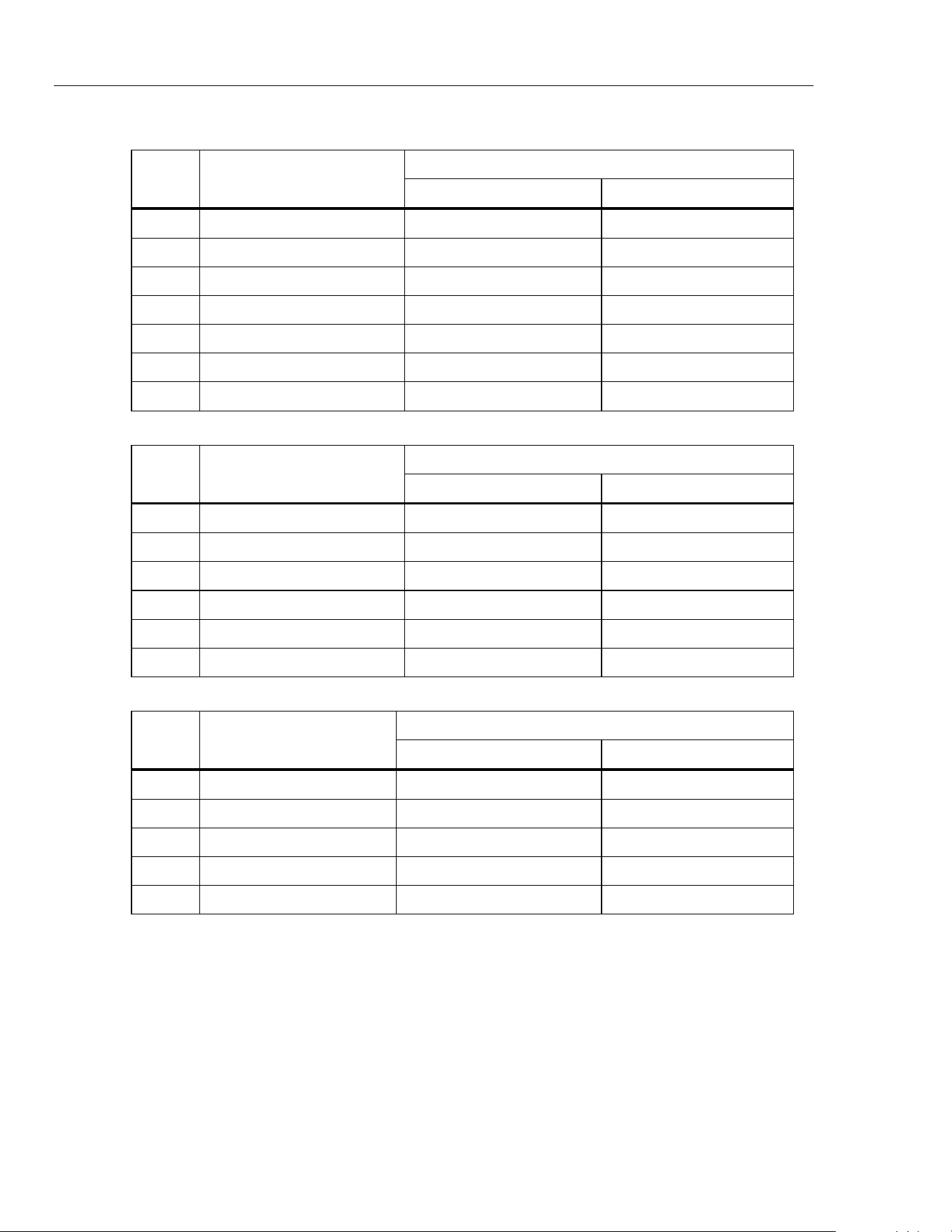
Volts DC Measure Accuracy Tests
UUT Meter Reading Limit
Step Calibrator Output
Low High
1 0.00 V -0.02 V 0.02 V
2 10.00 V 9.96 V 10.04 V
3 -10.00 V -10.04 V -9.96 V
4 20.00 V 19.94 V 20.06 V
5 -20.00 V -20.06 V -19.94 V
6 30.00 V 29.92 V 30.08 V
7 -30.00 V -30.08 V -29.92 V
mA DC Source Accuracy Tests
DMM Reading Limit
Step UUT Meter Output
Low High
1 0.00 mA -0.02 mA 0.02 mA
2 4.00 mA 3.97 mA 4.03 mA
3 8.00 mA 7.96 mA 8.04 mA
4 12.00 mA 11.96 mA 12.04 mA
5 20.00 mA 19.94 mA 20.06 mA
6 24.00 mA 23.93 mA 24.07 mA
Volts DC Source Accuracy Tests
DMM Reading Limit
Step UUT Meter Output
Low High
1 0.00 V -0.02 V 0.02 V
2 2.50 V 2.47 V 2.53 V
3 5.00 V 4.97 V 5.03 V
4 7.50 V 7.46 V 7.54 V
5 10.00 V 9.96 V 10.04 V
Calibration Adjustment
The Meter features closed-case calibration adjustment with a known reference source.
The Meter measures the applied reference source, calculates correction factors, and keeps
the correction factors in nonvolatile memory.
Before you start calibration adjustment, let the Meter stabilize to room temperature.
1.888.610.7664 sales@GlobalTestSupply.com
Fluke-Direct.com
Milliamp Process Clamp Meter
Calibration Adjustment
11
To turn on Calibration mode:
1. Remove the batteries and substitute with a lab supply set to 6 V dc.
2. Open the battery door. The calibration button is usually hidden by the factory
calibration seal.
3. Use a small probe and push the calibration button longer than 2 seconds. See Figure
4.
Calibration Button
gep01.eps
Figure 4. Accessing the Calibration Button
There are five Meter functions to adjust:
1. Clamp measure
2. mA measure
3. Volt measure (773 only)
4. mA source
5. Volt source (773 only)
Table 3 shows the Meter buttons you use to select a function to be calibrated.
Table 3. Calibration Functions
Button Calibration Function Description
L Engages mA function
J Identifies V dc function
C Identifies Clamp function
T
Toggles between measure and source modes
1.888.610.7664 sales@GlobalTestSupply.com
Fluke-Direct.com
772/773
Calibration Manual
12
Table 4 shows the Meter buttons you use to adjust the Meters calibration.
Table 4. Calibration Adjustments
Button Calibration Adjustment Description
Q
A short button push (1 second) changes the Meter to the first calibration step
A long button push exits the Meters calibration mode
D
G
Adjust source output in large steps
E
F
Adjust source output in small steps
H Forward to subsequent calibration step
The Meter display shows the value in each adjustment step.
• In Measure mode, the shown value is the calibrator input.
• In Source mode, the shown value is the Meter output.
To exit Calibration mode:
Push the calibration button a second time to keep new calibration constants and exit
calibration mode.
Calibration Error Messages
The calibration error messages that the Meter can show are in Table 5. Steps to remove
the messages are also shown in the table.
Table 5. Error Messages
Error Message Cause of Error Removal Steps
Cal Meter not calibrated, use default parameter Do all adjustments
Err Code area checksum error Meter repair is necessary
1.888.610.7664 sales@GlobalTestSupply.com
Fluke-Direct.com
Milliamp Process Clamp Meter
Calibration Adjustment
13
mA DC Clamp Measure Adjustment Procedure
To adjust the Clamp Measure function, use the Calibrator to apply the necessary Meter
input and do the steps in Table 6.
Table 6. Clamp Measure Adjustment Procedure
Step Meter Display Calibrator Output Procedure
1 0.00 mA 0.00 mA Stop for 10 seconds, push H
2 -20.00mA -20.00 mA Push H
3 0.00mA 0.00 mA Stop for 10 seconds, push Hold button
4 20.00mA 20.00 mA Push H
5 0.00 mA 0.00 mA Stop for 10 seconds, push H
6 -100.00mA -100.00 mA Push H
7 0.00mA 0.00 mA Stop for 10 seconds, push H
8 10.00mA 100.00 mA Push H
9 Save -- Push H
mA DC Measure Adjustment Procedure
To adjust the mA Measure function, use the Calibrator to apply the necessary Meter input
and do the steps in Table 7.
Table 7. mA Measure Adjustment Procedure
Step Meter Display Calibrator Output Procedure
1 -20.00 mA -20.00 mA Push H
2 0.00 mA 0.00 mA Push H
3 20.00 mA 20.00 mA Push H
4 Save -- Push H
Volts DC Measure Adjustment Procedure
To adjust the Volt Measure function, use the Calibrator to apply the necessary Meter
input and do the steps in Table 8.
Table 8. Volt Measure Adjustment Procedure
Step Meter Display Calibrator Output Procedure
1 -30.00V -30.00 V Push H
2 0.00V 0.00 V Push H
3 30.00V 30.00 V Push H
4 Save -- Push H
1.888.610.7664 sales@GlobalTestSupply.com
Fluke-Direct.com
772/773
Calibration Manual
14
mA DC Source Adjust Procedure
To adjust the mA Source function, use the Calibrator to apply the necessary Meter input
and do the steps in Table 9.
Table 9. mA Source Adjustment Procedure
Step Meter LCD display Action
1 4.00 mA Adjust until Meter output is 4.00 mA, push H
2 20.00 mA Adjust until Meter output is 20.00 mA, push H
4 Save Push H
Volts DC Source Adjust Procedure (773 Only)
To adjust the Volt Source function, use the Calibrator to apply the necessary Meter input
and do the steps in Table 10.
Table 10. Volt Source Adjustment Procedure
Step Meter LCD display Action
1 0.00 V Adjust until Meter output is 0.00 V, push H
2 10.00 V Adjust until Meter output is 10.00 V, push H
4 Save Push H
1.888.610.7664 sales@GlobalTestSupply.com
Fluke-Direct.com
Milliamp Process Clamp Meter
Replaceable Parts
15
Replaceable Parts
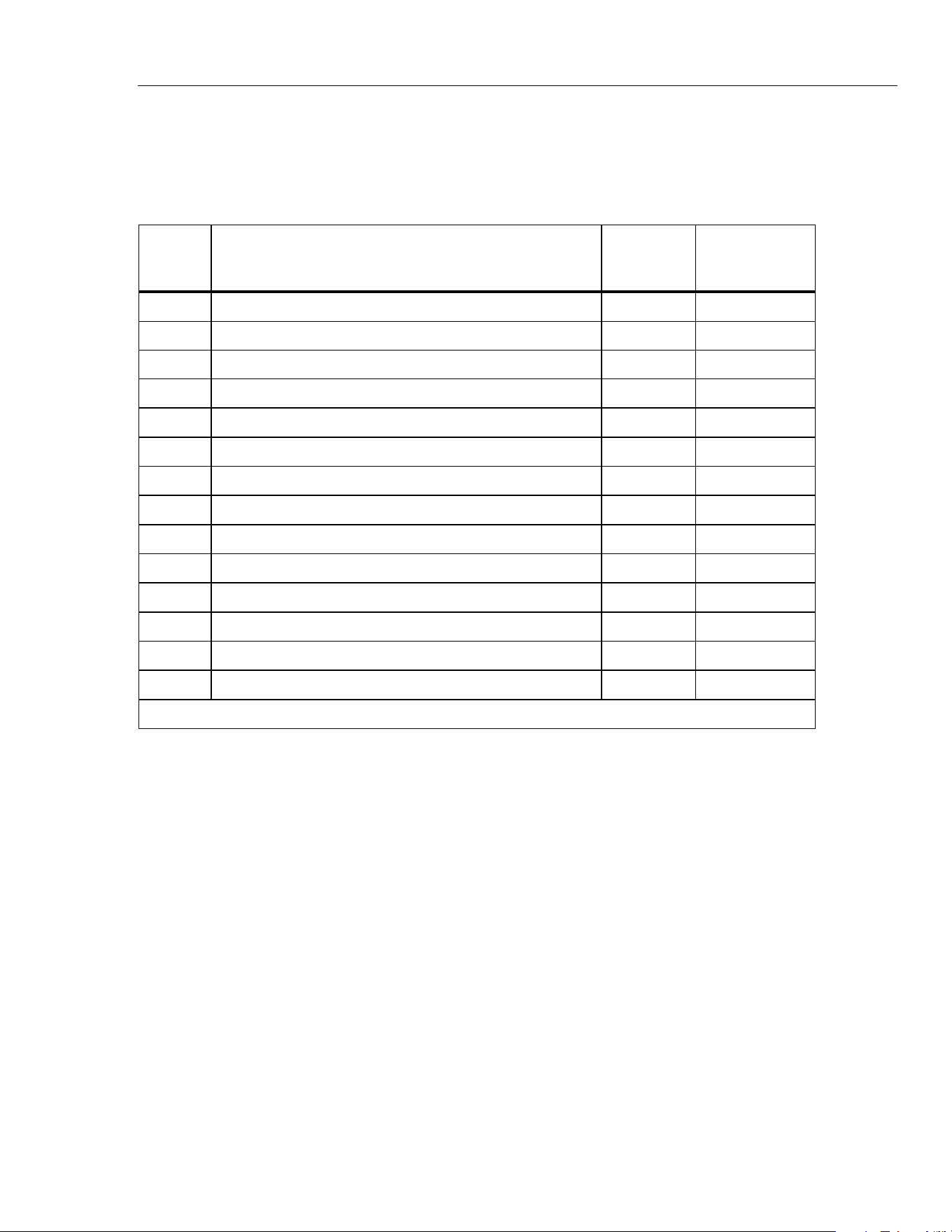
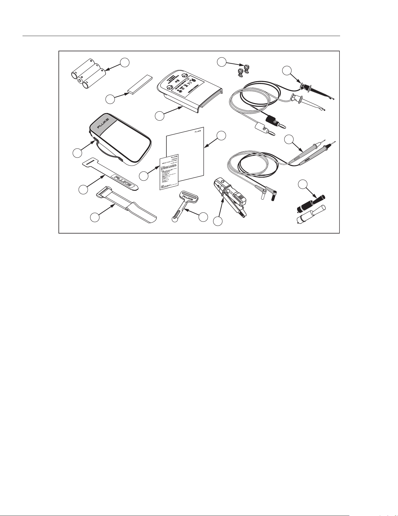
Table 11 and Figure 5 show all replaceable parts.
Table 11. Replaceable Parts
Item Description Quantity
Part or
Model
Number
A AA Batteries, 1.5 V 4 376756
B Absorber 1 3369914
C Battery door 1 3350978
D Fastener 2 948609
E Soft Carrying Case 1 3351060
F Instruction Sheet 1 3351049
G Calibration Manual 1 3362376
H TL940 Mini Hook with Test Lead 1 Set 1616705
I TL75- Test Leads 1 Set 855742
J AC72 Detachable Clip 2 1670095
K Velcro Strip 1 3031302
L TPAK, Strap 17 inches 1 669967
M Hanger 1 337574
N *Jaw Assembly 1 Set 3350957
*Re-calibration is required after jaw assembly is replaced.
1.888.610.7664 sales@GlobalTestSupply.com
Fluke-Direct.com
772/773
Calibration Manual
16
®
772/773
Milliamp Process Clamp Meter
Calibration Manual
No
v
e
m
b
e
r
2
0
0
7
©
2007
F
l
uke
Co
r
poration
,
All
r
i
g
ht
s
rese
r
v
ed
.
Printe
d
in
USA.
Prod
u
ct
specif
i
c
ati
o
ns
ar
e subject
to
change
without
not
i
c
e.
Al
l
p
r
o
d
u
c
t
n
a
me
s
ar
e
tr
a
d
e
marks
o
f
the
ir
r
e
s
p
e
c
tiv
e
c
ompa
nie
s
.
7
9
10
8
4
3
2
1
6
5
11
12
13
14
gep04.eps
Figure 5. Replaceable Parts
1.888.610.7664 sales@GlobalTestSupply.com
Fluke-Direct.com