Loading ...
Loading ...
Loading ...
15
For the Installer
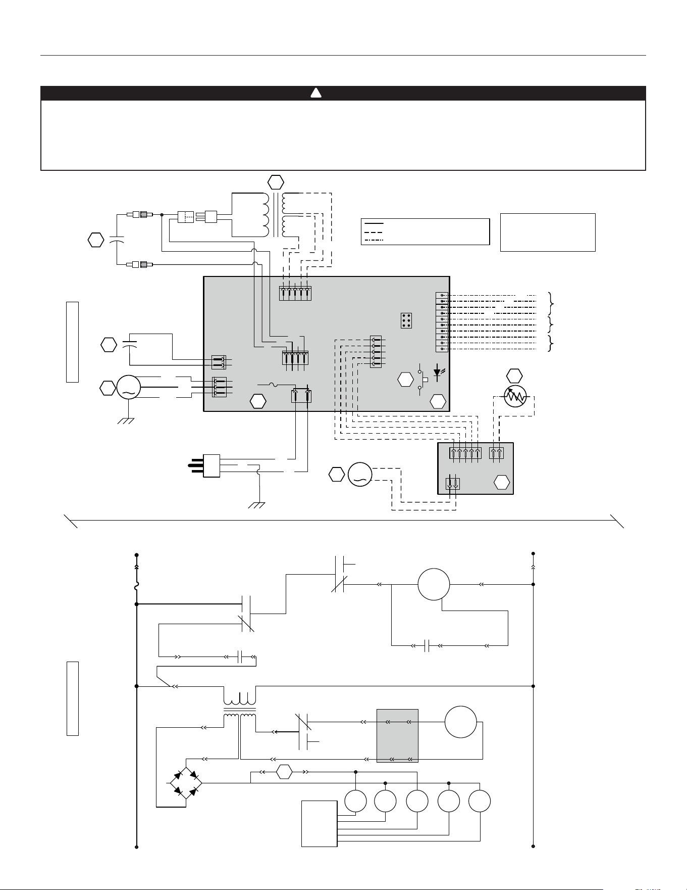
9. WIRING DIAGRAMS
• Risk of electric shocks. Before performing any maintenance or servicing, always disconnect the unit from its
power source.
• This product is equipped with an overload protection (fuse). A blown fuse indicates an overload or a short-circuit
situation. If the fuse blows, unplug the product from the outlet. Discontinue using the unit and contact technical
support.
WARNING
!
BK
W
G
A1
J6
1
2
J10
1
2
J14
10
9
8
7
6
5
4
3
2
1
12345
J12
J13
ICP
21345
J8
4321
J9
24 V Class 2
9.5 V
Class 2
C1
5 µF
2154321
12
J3
J2
J1
M2
A2
C2
F1
T1
120 VAC
60 Hz
S1
OVERRIDE SWITCH
(OPTIONAL)
FIELD WIRING
REMOTE CONTROL
FURNACE BLOWER
INTERLOCK (OPTIONAL)
THERMISTOR
DAMPER ELECTRONIC
ASSEMBLY
ELECTRONIC ASSEMBLY
DAMPER MOTOR
3A
3AG TYPE
COLOR CODE
t˚
VE0335A
M
J4-1
J9-3
J6-1
J6-2
J4-2
M
J2-1
J3-1
J3-2J2-2
J12-2
K4
K3
K2
T1
+-
~
~
L
INE
N
EUTRAL
120 VAC
A2
DAMPER MOTOR
BLOWER MOTOR
C1
M
OTOR
C
APACITOR
CPU
K2 K3 K4
3A
J12-1
J10-2
J10-1
J4-3
J9-1
24 VAC
9.5 VAC
C2
M
OTOR
S
PEED
J8-4
J8-5
J8-2
J8-1
LOGIC DIAGRAM
WIRING DIAGRAM
M1
BL
BR
J4
1
2
3
BK
B
G
R
R
G
BK
Y
Y
OL
OC
I
LINE VOLTAGE
CLASS 2 LOW VOLTAGE FACTORY WIRING
CLASS 2 LOW VOLTAGE FIELD WIRING
13 µF
BLACK
BLUE
BROWN
GREEN
BK
BL
BR
G
O
RANGE
RED
WHITE
YELLOW
O
R
W
Y
O
O
Y
Y
R1
BLOWER
MOTOR
MOTOR
CAPACITOR
K1 K5
S1
J11-2 J11-1
BK
R
W
9.1 K7 ERV AND 40E UNITS
Loading ...
Loading ...
Loading ...