
TS 348XD
EN Operator's manual 2-40
ES-MX Manual del usuario 41-84

Contents
Introduction..................................................................... 2
Safety..............................................................................6
Assembly...................................................................... 10
Operation...................................................................... 13
Maintenance................................................................. 18
Troubleshooting............................................................ 33
Transportation, storage and disposal........................... 37
Storage......................................................................... 38
Disposal........................................................................ 39
Technical data.............................................................. 39
Service..........................................................................40
Appendix ......................................................................85
Introduction
Pre-delivery inspection and product
numbers
Note: A pre-delivery inspection has been done of this
product. Make sure that you receive a signed copy of
the pre-delivery inspection document from your dealer.
Service agent contact informa-
tion:
This operator’s manual belongs to product with product number / serial number:
/
Engine:
Transmission:
Product description
This is a lawn tractor with the cutting deck installed
between the front and rear axles. It has a 4-stroke
engine that uses gasoline.
Optional accessories:
• Grass catcher
• Mulch plug
Intended use
This product is only used to cut grass in private gardens
and on private garden slopes with not more than 15°
slope. It is not to be used in public parks, sports
grounds, in farming or in forestry. Only use the product
with accessories that are approved by the manufacturer.
To use the product differently is incorrect use. It will void
your warranty and reject the responsibility for damage to
the user of third parties on the part of the manufacturer.
Refer to local directives for the operation of lawn
mowers.
Support / Help
If you require assistance or have questions concerning
the application, operation, maintenance or parts for your
product:
• Visit our website: www.husqvarna.com
• Call Us Toll Free: 1-800-487-5951
2 2231 - 003 - 22.09.2023
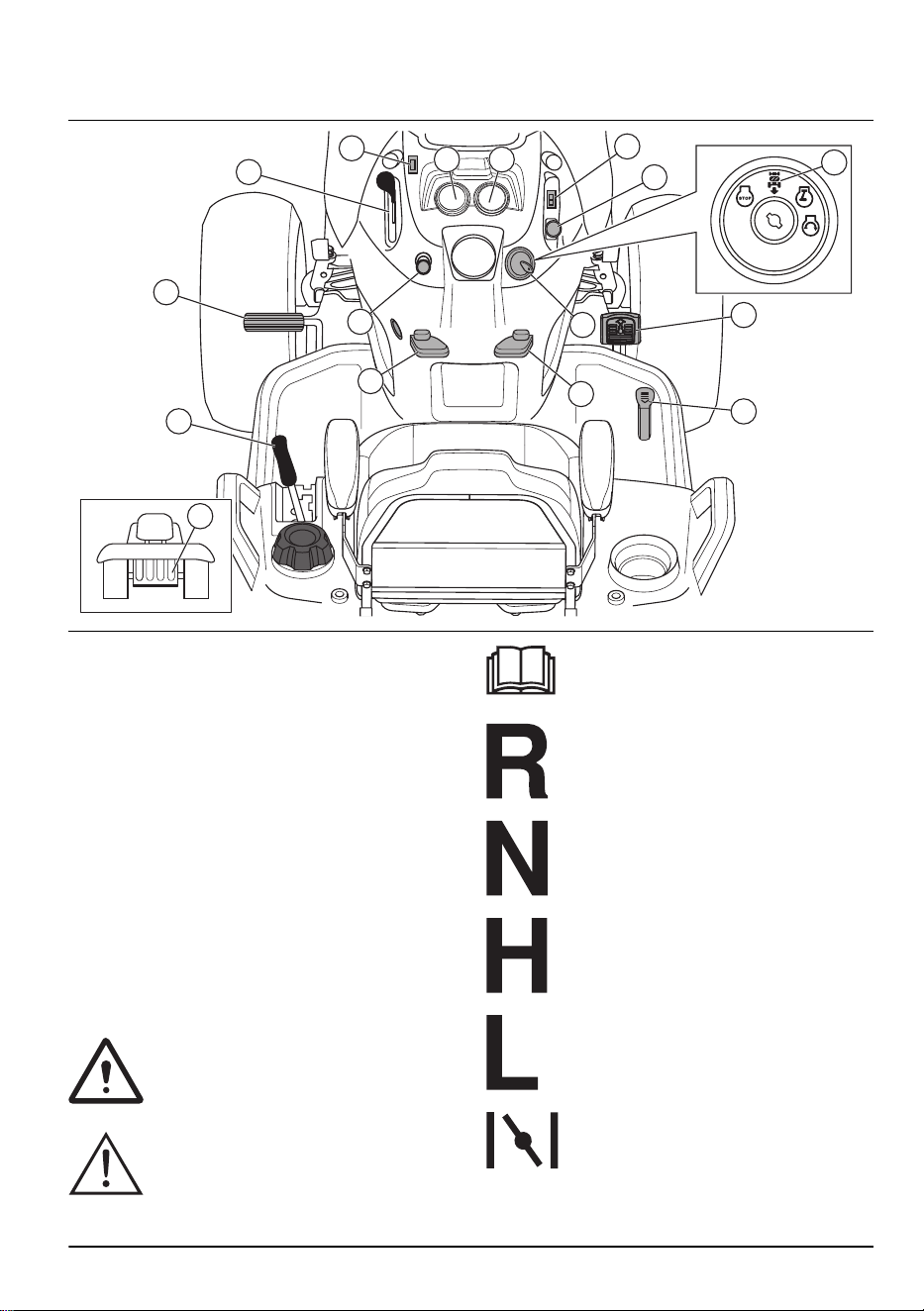
Product overview
16
15
14
1
2
13
12
11
7
6
5
8
9
43
10
1. Throttle control
2. Light switch
3. Hour meter
4. Ampere meter
5. Differential lock switch
6. PTO button
7. Ignition switch
8. Reverse operation system (ROS) ON position
9. Forward drive pedal
10. Reverse drive pedal
11. Cruise control lever
12. Parking brake lever
13. Choke control
14. Brake pedal
15. Attachment lift lever
16. Freewheel lever
Symbols on the product
Warning! Be careful and use the product
correctly. This product can cause serious
injury or death to the operator or others.
CAUTION: Incorrect use can result in
damage to the product or personal
property.
Read the operator's manual carefully
and make sure that you understand the
instructions before you use this product.
Reverse.
Neutral.
High.
Low.
Choke.
2231 - 003 - 22.09.2023 3

Fast.
Slow.
Ignition switch.
Engine off.
Engine start.
Engine on.
Differential lock.
Brake and clutch pedal.
Parking brake.
Cutting height.
Cutting deck lift.
Reverse operation system (ROS).
Reverse.
Forward.
Lights on.
Battery.
The blades are disengaged.
The blades are engaged.
Dangerous, keep hands and feet away
from this area.
Fuel.
Use protective glasses.
Use approved hearing protection.
Keep the area clear when you move
forward.
Do not use the product if persons,
especially children, or animals, are near.
Slope risk. Do not operate the product
straight up a slope that is more then 15°.
4 2231 - 003 - 22.09.2023
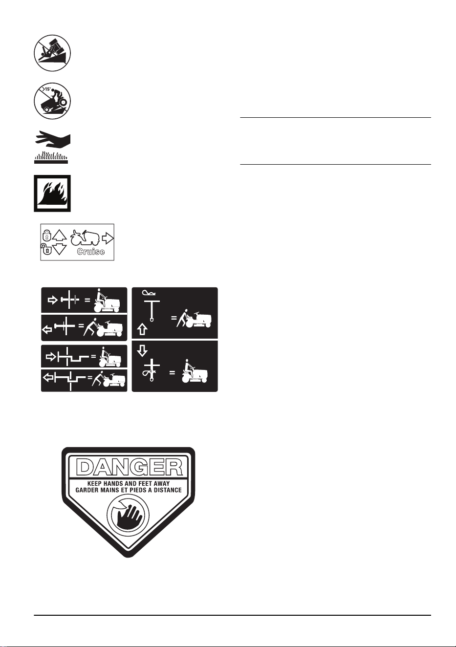
Slope risk. Do not operate horizontally on
a slope.
Slope risk. Do not operate the product
straight down a slope that is more than
15°.
The hot surfaces symbol show a risk,
which, if not obeyed, can cause death,
serious injury and/or damage.
The fire symbol shows a risk, which, if not
obeyed, can cause death, serious injury
and/or damage.
Cruise control.
Freewheel (automatic models only).
Label on the product
DANGER – Keep hands and feet away.
Hour meter
The hour meter shows how many hours the engine has
been in operation. Refer to
Product overview on page 3
for the position of the hour meter.
To manually reset the hour meter, turn the ignition key to
the on position and then to the "STOP" position 5 times.
Note: The hour meter only stops when the ignition key
is in the "STOP" position. Make sure that the ignition
key stays in the "STOP" position when the engine has
stopped.
Product damage
We are not responsible for damages to our product if:
• the product is incorrectly repaired.
• the product is repaired with parts that are not
from the manufacturer or not approved by the
manufacturer.
• the product has an accessory that is not from the
manufacturer or not approved by the manufacturer.
• the product is not repaired at an approved service
center or by an approved authority.
2231 - 003 - 22.09.2023 5
Safety
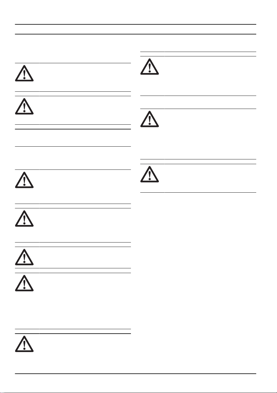
Safety definitions
Warnings, cautions and notes are used to point out
specially important parts of the manual.
WARNING: Used if there is a risk of
injury or death for the operator or bystanders
if the instructions in the manual are not
obeyed.
CAUTION: Used if there is a risk of
damage to the product, other materials or
the adjacent area if the instructions in the
manual are not obeyed.
Note: Used to give more information that is necessary
in a given situation.
Safe Operation Practices for Ride-On
Mowers
WARNING: This product is capable of
amputating hands and feet and throwing
objects. Failure to observe the following
safety instructions could result in serious
injury or death.
WARNING: In order to prevent
accidental starting when setting up,
transporting, adjusting pr making repairs,
always disconnect spark plug wire and place
wire where it cannot contact spark plug.
WARNING: Do not coast down a hill in
neutral, you may lose control of the tractor.
WARNING: Tow only attachments that
are recommended by and comply with
specifications of the manufacturer of your
tractor. Use common sense when towing.
Operate only at the lowest possible speed
when on a slope. Too heavy of a load, while
on a slope, is dangerous. Tires can lose
traction with the ground and cause you to
lose control of your tractor.
WARNING: Engine exhaust, some
of its constituents, and certain vehicle
components contain or emit chemicals
known to the State of California to
cause cancer and birth defects or other
reproductive harm.
WARNING: Battery posts, terminals
and related ac ces so ries contain lead and
lead compounds, chem i cals known to the
State of Cal i for nia to cause can cer and
birth defects or oth er re pro duc tive harm.
Wash hands after handling.
I. CHILDREN
WARNING: CHILDREN CAN BE
INJURED BY THIS EQUIPMENT.
The American Academy of Pediatrics
recommends that children be a minimum
of 12 years of age before operating a
pedestrian controlled lawn mower and
minimum of 16 years of age before
operating a riding lawn mower.
WARNING: CHILDREN CAN BE
SERIOUSLY INJURED OR KILLED BY
THIS EQUIPMENT. Carefully read and
follow all the safety instructions below.
Tragic accidents can occur if the operator is not alert to
the presence of children. Children are often attracted to
the machine and the mowing activity. Never assume that
children will remain where you last saw them.
• Keep children out of the mowing area and in the
watchful care of a responsible adult other than the
operator.
• Be alert and turn machine off if a children enters the
area.
• Before and while backing, look behind and down for
small children.
• Never carry children, even with the blades shut off.
They may fall off and be seriously injured or interfere
with safe machine operation. Children who have
been given rides in the past may suddenly appear
in the mowing area for another ride and be run over
or backed over by the machine.
• Never allow children to operate the machine.
• Use extreme caution when approaching blind
corners, shrubs, trees, or other objects that may
block your view of a child.
II. GENERAL OPERATION
• Read, understand, and follow all instructions on the
machine and in the manual before starting.
• Do not put hands or feet near rotating parts or under
the machine. Keep clear of the discharge opening at
all times.
6
2231 - 003 - 22.09.2023
• Only allow responsible adults, who are familiar with
the instructions, to operate the machine.
• Clear the area of objects such as rocks, toys, wire,
etc., which could be picked up and thrown by the
blades.
• Ensure the area is clear of bystanders before
operating. Stop machine if anyone enters the area.
• Never carry passengers.
• Do not mow in reverse unless absolutely necessary.
Always look down and behind before and while
backing.
• Never direct discharged material toward anyone.
Avoid discharging material against a wall or
obstruction. Material may ricochet back toward
operator. Stop the blades when crossing gravel
surfaces.
• Do not operate machine without the entire grass
catcher, discharge chute, or other safety devices in
place and working.
• Slow down before turning.
• Never leave a running machine unattended. Always
turn off blades, set parking blade, and stop engine
before dismounting.
• Disengage blades when not mowing. Shut off engine
and wait for all parts to come to complete stop
before cleaning the machine, removing the grass
catcher, or unclogging the discharge chute.
• Operate machine only in daylight or good artificial
light.
• Do not operate the machine while under the
influence of alcohol or drugs.
• Watch for traffic when operating near or crossing
roadways.
• Use extreme caution when loading or unloading the
machine into a trailer or truck.
• Always wear eye protection when operating
machine.
• Use ear protectors to avoid damage to hearing.
• Data indicates that operators, age 60 years and
above, are involved in a large percentage of riding
mower-related injuries. These operators should
evaluate their ability to operate the riding mower
safely enough to protect themselves and others from
serious injury.
• Follow the manufacturer's recommendation for wheel
weights or counterweights.
• Keep machine free of grass, leaves or other debris
build-up which can touch hot exhaust/engine parts
and burn. Do not allow the mower deck to plow
leaves or other debris which can cause build-up to
occur. Clean any oil or fuel spillage before operating
or storing the machine. Allow machine to cool before
storage.
Safety instructions for operation
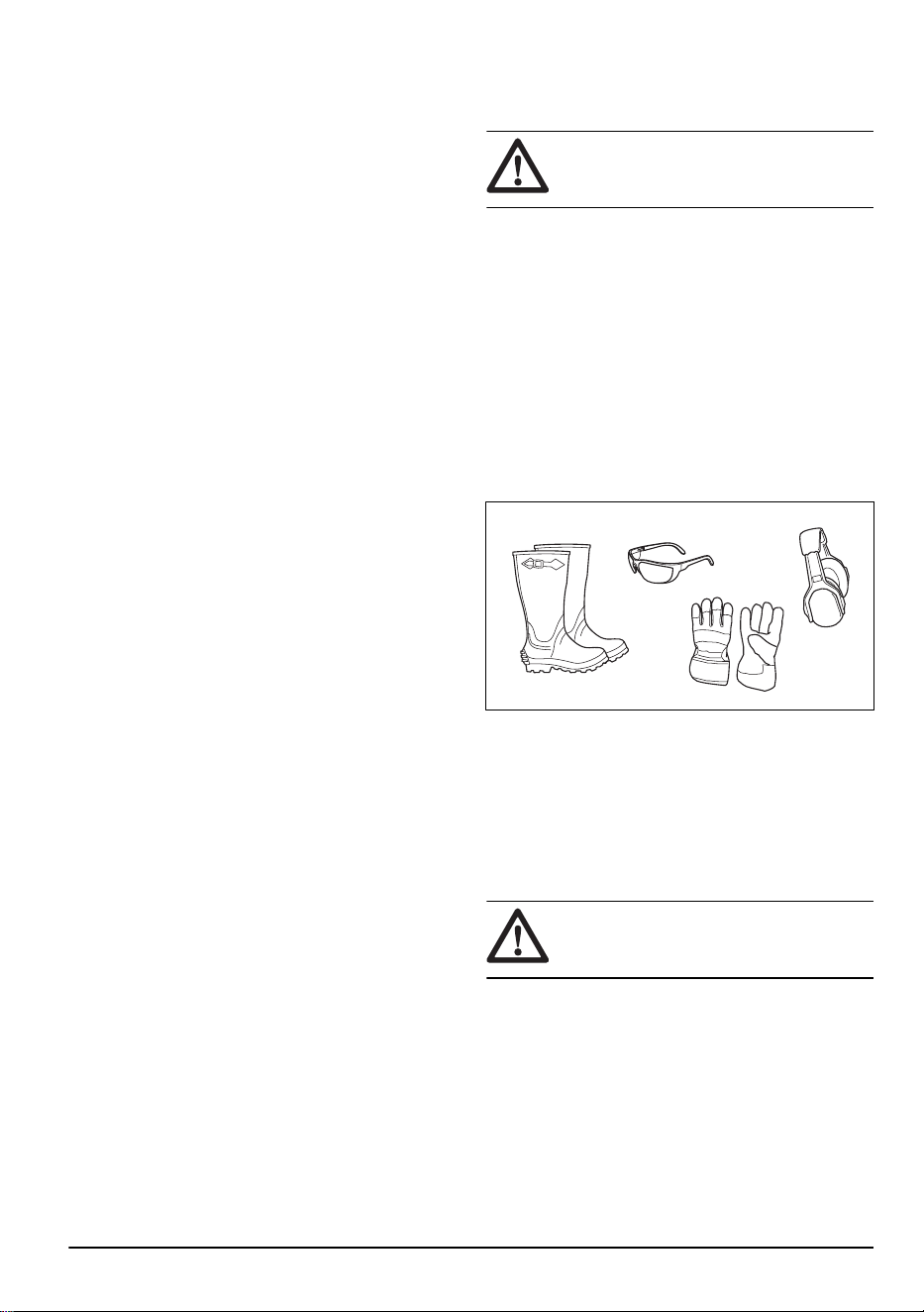
Personal protective equipment
WARNING: Read the warning
instructions that follow before you use the
product.
• Use approved personal protective equipment when
you use the product. Personal protective equipment
cannot fully prevent injury but it decreases the
degree of injury if an accident does occur. Let your
dealer help you select the right equipment.
• Always wear approved hearing protection. Long term
exposure to noise can result in permanent hearing
impairment.
• Always wear safety glasses or eye protection while
you operate the product or do maintenance or
repairs.
• Always wear protective shoes or protective boots.
Steel toes are recommended. Do not use the
product barefoot.
• Wear gloves when necessary, for example when you
attach, examine or clean the cutting equipment.
• Do not wear loose-fitting clothing, jewelry or other
items that can get caught in moving parts.
• Do not wear shorts when you operate the product.
• Keep first aid equipment and fire extinguisher close
at hand.
Safety devices on the product
WARNING:
Read the warning
instructions that follow before you use the
product.
• Do not use a product with safety devices that are
damaged or do not operate correctly. Do a check of
the safety devices regularly. If the safety devices are
damaged, speak to your Husqvarna service agent.
• Do not make modifications on safety devices. Do
not use the product if protective plates, protective
covers, safety switches or other protective devices
are not attached or are damaged.
2231 - 003 - 22.09.2023
7

To do a check of the operator presence control (OPC)
WARNING: Do not operate the product
with an operator presence control (OPC)
that does not operate correctly. If the
OPC does not operate correctly, repair it
immediately. Speak to an approved service
agent.
• Make sure that the engine cannot start unless the
brake pedal is pushed down fully and the cutting
deck is disengaged.
• Make sure that the engine stops when the operator
goes away from the seat when the parking brake is
disengaged.
• Make sure that the engine stops when the operator
goes away from the seat when the cutting deck is
engaged.
• Make sure that the clutch control for the cutting deck
cannot operate when the operator is away from the
seat.
To do a check of the reverse operation system (ROS)
If the reverse operation system does not operate
correctly, repair the product immediately. Speak to an
approved service agent.
1. Start the product. Refer to
To start the product on
page 13
.
2. Engage the cutting deck. Refer to
To engage and
disengage the cutting deck on page 17
.
3. Make sure that the engine stops when you try to
reverse with the ignition key is in the on position (A).
BA
4. Start the product and engage the cutting deck again.
5. Turn the ignition switch to the ROS on position (B).
6. Make sure that the engine does not stop when you
reverse with the ignition key in the ROS on position.
To do a check of the brake
WARNING:
Brake maintenance is
necessary if the product uses more than 5
ft (1.5 m) to stop at the highest speed in the
highest gear on a level, dry surface.
1. Park the product on a level, dry concrete or paved
surface. Push the brake pedal down fully and
engage the parking brake.
2. Set the freewheel control to the “transmission
disengaged” position to disengage the transmission.
3. The rear wheels must lock and skid when you try
to manually push the product forward. If the rear
wheels rotate, then brake maintenance is necessary.
4. Speak to an approved service center.
Parking brake
WARNING: If the parking brake does
not work, the product can start to move
and cause injury or damage. Make sure that
the parking brake is regularly examined and
adjusted.
Refer to
To do a check of the brake on page 8
.
Muffler
The muffler keeps the noise levels to a minimum and
sends the exhaust fumes away from the operator.
Do not use the product if the muffler is missing or
damaged. A damaged muffler increases the noise level
and the risk of fire.
WARNING: The muffler becomes very
hot during and after use and when the
engine operates at idle speed. Be careful
near flammable materials and/or fumes to
prevent fire.
To cut grass on slopes
WARNING:
Read the warning
instructions that follow before you use the
product.
• To cut grass on slopes increases the risk that you
can not control the product and that it overturns. This
can cause injury or death. It is necessary to cut the
grass carefully on all slopes. If you cannot reverse
up a slope or if you do not feel safe, do not cut it.
• Remove stones, branches and other obstacles.
• Cut up and down the slope, not from side to side.
• Do not move down a slope with the cutting deck
lifted.
• Do not operate the product on ground that slopes
more than 15°.
8
2231 - 003 - 22.09.2023

>15°
• Do not start or stop on a slope.
• Move smoothly and slowly on slopes.
• Do not make sudden changes in speed or direction.
• Do not turn more than necessary. Turn slowly and
gradually when you move down a slope. Move at low
speed. Turn the wheel carefully.
• Look out for and do not move across furrows, holes
and bumps. There is a higher risk that the product
overturns on ground that is not flat. Long grass can
hide obstacles.
• Do not cut grass near edges, ditches or banks. Keep
at least the width of the product away from these
hazards. The product can suddenly overturn if a
wheel moves across the edge of a steep slope or
a ditch, or if an edge gives way.
• Do not mow wet grass. It is slippery, and tires can
lose their grip so that the product skids.
• Do not put your foot on the ground to try to make the
product more stable.
• Move very carefully if an accessory or other object is
attached that can make the product less stable.
Fuel safety
WARNING:
Read the warning
instructions that follow before you use the
product.
• Fuel is flammable and the fumes are explosive. Be
careful with fuel to prevent injury, fire and explosion.
• Do not breathe in the fuel fumes. The fuel fumes are
poisonous and can cause injury. Make sure that the
airflow is sufficient.
• Do not remove the fuel tank cap or fill the fuel tank
when the engine is on.
• Make sure that the engine is cool before you refuel.
• Do not fill fuel in an indoor area. Insufficient airflow
can cause injury or death because of asphyxiation or
carbon monoxide poisoning.
• Do not smoke near the fuel or the engine.
• Do not put hot objects near the fuel or the engine.
• Do not fill fuel near sparks or flames.
• Before you refuel, open the fuel tank cap slowly and
release the pressure carefully.
• Fuel on your skin can cause injury. If you get fuel on
your skin, use soap and water to remove the fuel.
• If you spill fuel on your clothing, change clothing
immediately.
• Do not fill the fuel tank fully. Heat causes the fuel to
expand. Keep a space at the top of the fuel tank.
• Tighten the fuel tank cap fully. If the fuel tank cap is
not tightened, there is a risk of fire.
• Before you start the product, move the product to a
minimum of 3 m/10 ft from where you refueled.
• Do not start the product if there is fuel or engine
oil on the product. Remove the unwanted fuel and
engine oil and let the product dry before you start the
engine.
• Examine the engine for leaks regularly. If there are
leaks in the fuel system, do not start the engine until
the leaks are repaired.
• Do not use your fingers to examine the engine for
leaks.
• Keep fuel in approved containers only.
• When the product and fuel is in storage, make sure
that fuel and fuel fumes cannot cause damage.
• Drain the fuel in an approved container outdoors and
away from sparks and flames.
Battery safety
WARNING: A damaged battery can
cause an explosion and cause injury. If the
battery has a deformation or is damaged,
speak to an approved Husqvarna service
agent.
WARNING: Read the warning
instructions that follow before you use the
product.
• Use protective glasses when you are near batteries.
• Do not wear watches, jewelry or other metal objects
near the battery.
• Keep the battery out of reach for children.
• Charge the battery in a space with good airflow.
• Keep flammable materials at a minimum clearance
of 1 m when you charge the battery.
• Discard replaced batteries. See
Disposal on page
39
.
• Explosive gases can come from the battery. Do not
smoke near the battery. Keep the battery away from
open flames and sparks.
Transport safety
• Use an approved transport vehicle for transportation
of the product.
• The product is heavy and can cause crush injuries.
Be careful when you load it onto or off a vehicle or
trailer.
• A markets national or local regulations can set limit
to the transportation of the product.
2231 - 003 - 22.09.2023
9
• The operator of the transport vehicle is responsible
to attach the product safely during transport. Refer to
Transportation on page 37
.
Safety instructions for maintenance
WARNING: The product is heavy and
can cause injury or damage to property or
the adjacent area. Do not do maintenance
on the engine or the cutting deck without
these conditions:
• The engine is off.
• The product is parked on a level surface.
• The parking brake is applied.
• The ignition key is removed.
• The cutting deck is disengaged.
• The ignition cables are removed from the
plugs.
WARNING: The exhaust fumes from
the engine contain carbon monoxide, an
odorless, poisonous and very dangerous
gas. Do not run the product in closed spaces
or spaces with not sufficient air flow.
WARNING: Read the warning
instructions that follow before you do
maintenance on the product.
• For best performance and safety, do maintenance
on the product regularly as given in the maintenance
schedule. Refer to
Maintenance schedule on page
19
.
• Electrical shocks can cause injuries. Do not touch
the cables when the engine is on. Do not do a
function test on the ignition system with your fingers.
• Do not start the engine if the protective covers are
removed. There is a high risk of injury caused by
moving or hot parts.
• Let the product become cool before you do
maintenance near the engine.
• The blades are sharp and can cause cuts. Wind
protection around the blades or use protective
gloves when you do work on the blades.
• Always put the cutting deck in servicing position to
clean it. Do not park the product near the edge of a
ditch or slope to get access to the cutting deck.
CAUTION: Read the caution
instructions that follow before you use the
product.
• Do not turn over the engine if the spark plug or
ignition cable is removed.
• Make sure that all nuts and bolts are tightened
correctly and that the equipment is in good condition.
• Do not change the adjustment of governors. If the
engine speed is too high, the product components
can become damaged.
• The product is approved only with the equipment
supplied or recommended by the manufacturer.
Assembly
Introduction
WARNING: Read and understand the
safety chapter before you assemble the
product.
To remove the product from the carton
1. Remove loose parts included with the product.
2. Remove the end panels.
3. Remove the side panels and put them on a flat
surface.
4. Remove all package materials.
5. Remove the product from the carton and make sure
no loose parts are left in the carton.
Assembly tools
Note: A socket wrench set will make the assembly
procedure easier.
• 1/2" (13 mm) wrench
• Tire pressure gauge
• Utility knife
• Pliers
Loose parts that need assembly
The product is not fully assembled. The parts that follow
are loose when the product is purchased.
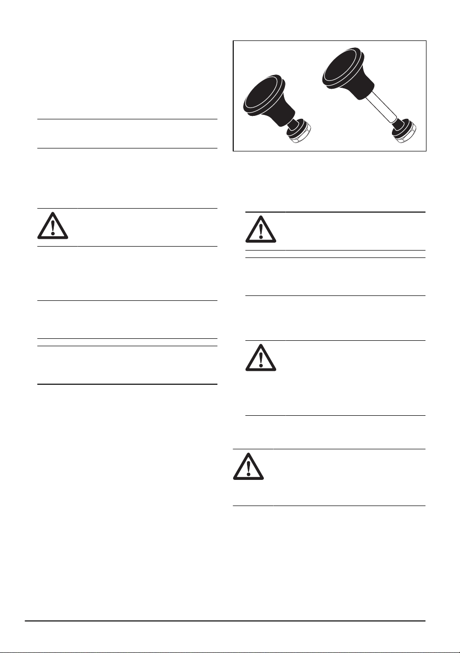
Key, 2 pcs
Slope sheet, 1 pcs
Hex bolt, 2 pcs
10 2231 - 003 - 22.09.2023
Nuts, 2 pcs
Nozzle adapter, 1 pcs
Oil drain tube, 1 pcs
Seat adjustment knob, 2 pcs
Seat adjustment bolt, 2 pcs
Seat bumper, 2 pcs
Bolt for seat bumper, 2 pcs
Seat, 1 pcs
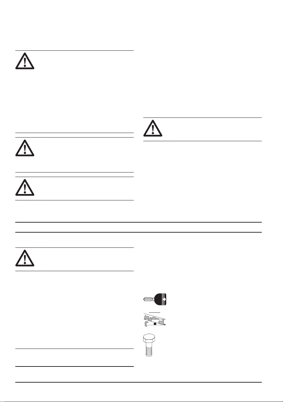
To install the seat
1. Fold the seat pan forward.
2. Install the 2 bumpers (A) to the seat pan (B) with the
2 bolts (C).
A
C
B
3. Hold the seat (D) in position and install 1 of the 2
seat adjustment knobs (E) in 1 of the adjustment
holes (F) in the seat pan.
E
G
D
F
H
4. Install the other seat adjustment knob (G).
5. Install the 2 bolts (H) in the slots in the seat pan.
6. Adjust the seat before you operate the product.
Refer to
To adjust the seat on page 12
.
2231 - 003 - 22.09.2023
11
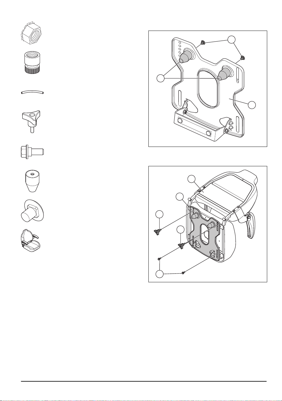
To adjust the seat
1. Fold the seat forward and remove the seat
adjustment knob (A).
A
B
2. Loosen the seat adjustment knob (B).
3. Move the seat until it is in a position where you can
push the brake and clutch pedals down.
4. Align one of the holes in the seat pan with the hole in
the seat and install the seat adjustment knob (A).
5. Tighten the 2 seat adjustment knobs fully.
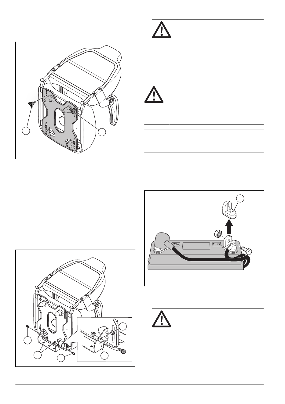
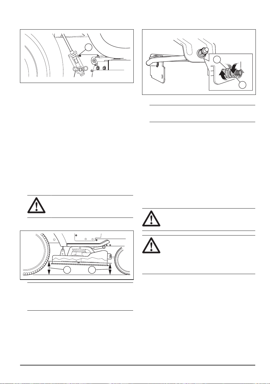
To adjust the seat height
The seat height can be adjusted into 2 positions, upper
position and lower position. The seat is installed in the
upper position from the factory.
1. Fold the seat forward.
2. Remove the 2 bolts (A) and the 2 nuts (B).
C
D
A
A
B
WARNING:
The seat and seat pan
comes loose when you remove the bolts
and the nuts.
3. Align the holes in the seat pan with the holes for the
upper position (C) or the lower position (D). Install
the bolts and the nuts.
4. Tighten all bolts fully.
To connect the battery
WARNING: Risk of electrical shock and
burn injuries. Do not use metal wristbands
or other metal accessories. Metal items that
touch the battery terminals can cause burn
injuries, electrical shock, and short circuit of
the battery.
Note: If it is after the year and month that is written on
the battery label, charge the battery. Charge the battery
for a minimum of 1 hour at 6–10 A.
1. Find the battery location below the seat or the
engine cover.
2. Lift the seat pan or the engine cover to the raised
position.
3. Remove the 2 terminal caps (A) and discard them.
A
4. Connect the red battery cable to the positive (+)
terminal and tighten the bolt and nut as shown. Move
the terminal cover on the terminal.
WARNING:
Risk of sparks. The red
battery cable must be connected to the
positive terminal before the black battery
cable is connected to the negative
terminal. This is to prevent sparks and
accidental grounding.
5. Connect the black cable to the negative (-) terminal
and tighten the bolt and nut fully.
12
2231 - 003 - 22.09.2023

6. Apply petroleum jelly on the battery cables to
prevent corrosion.
7. Lower the seat pan or the engine cover.
To move the product off the skid
1. Lift the cutting deck to its highest position. Use the
lift lever.
2. Push the clutch/brake pedal down to release the
parking brake.
3. Put the freewheel control in the "Transmission
disengaged" position, refer to
Transportation,
storage and disposal on page 37
.
4. Push the product forward off the skid.
5. Remove the strap that holds the deflector protection
up against the product.
To do a check after the assembly
• Make sure that all assembly instructions are
completed.
• Make sure that no remaining parts are in the
package.
• Make sure that the battery is prepared and charged
correctly.
• Make sure that the bolts for the seat are tightened
and that the seat is adjusted correctly.
• Make sure that the tires are correctly inflated.
• For best cutting results, make sure that the cutting
deck is balanced side to side and front to rear.
Make sure that the tires are correctly inflated for a
balanced cutting deck.
• Examine the cutting deck and the drive belts. Make
sure that the drive belts are installed correctly
around the pulleys and inner part of all belt keepers.
• Examine the electrical wires. Make sure that all wires
and connections are safe.
• Make sure that the freewheel control is in
the “Transmission engaged” position. Refer to
Transportation on page 37
.
• Make sure that the engine oil is at the correct level.
• Make sure that the tank is filled with the correct type
of fuel.
• Make sure that you know the location and function of
all controls.
• Make sure that the brake system is in safe to
operate condition.
• Make sure that the Operator Presence Control
(OPC) and the Reverse Operation System (ROS)
operate correctly. Refer to
To do a check of the
operator presence control (OPC) on page 8
and
To
do a check of the reverse operation system (ROS)
on page 8
.
• Remove the air from the transmission before
first use. Refer to
To remove the air from the
transmission on page 32
.
Operation
Introduction
WARNING: Read and understand the
safety chapter before you use the product.
To fill fuel
WARNING: Gasoline is very
flammable. Be careful and refuel outdoors.
Refer to
Fuel safety on page 9
.
CAUTION: Always use correct fuel
type. Incorrect fuel type causes damage to
the product.
• Use gasoline of the correct type. Refer to
Technical
data on page 39
. For more information about the
fuel, refer to the engine manual supplied by the
engine manufacturer.
• Do a check of the fuel level before each use and
refuel if necessary.
• Do not fully fill the fuel tank. Keep a space of a
minimum 1 in.
To start the product
To do before you start the product
WARNING: Before you operate the
product, carefully read and understand
the safety instructions and the operation
instructions.
1. Do a check of the engine oil level. Refer to
To do a
check of the engine oil level on page 29
.
2. Fill the fuel tank with fuel. Refer to
To fill fuel on
page 13
.
3. Disengage the freewheel mode. Refer to
To put the
product in freewheel mode on page 18
.
4. Sit in the seat in operation position.
5. Engage the parking brake. Refer to
To engage and
disengage the parking brake on page 16
.
6. Make sure that the cutting deck is disengaged. Refer
to
To engage and disengage the cutting deck on
page 17
.
To start a warm engine
1. Sit in the seat.
2231 - 003 - 22.09.2023 13
2. Make sure that the cutting deck is disengaged. Refer
to
To engage and disengage the cutting deck on
page 17
.
3. Put the cutting deck in transport position. Refer to
To set the cutting deck in transport position or mow
position on page 15
.
4. Move throttle control to fast position.
5. Pull out the choke control.
Note: For a warm engine start, it may not be
necessary to use the choke control.
6. Push down on the brake pedal fully and keep it
pushed down.
7. Put the ignition key into the ignition.
8. Turn the ignition key to the “START” position and
release the ignition key when the engine starts.
CAUTION: Do not operate the
starter continuously for more than 15
seconds for each minute.
9. When the engine has started, slowly push in
the choke control until the engine runs smoothly.
When the engine operates smoothly, the attached
equipment can be operated and you can operate the
forward and rearward drive.
Note: If the engine runs roughly, pull the choke
control out for a few seconds and then continue to
push the choke control in slowly.
Note: If the engine does not accept the load,
restart the engine and let it warm up for one minute.
Follow the instructions above.
To start a cold engine
1. Sit in the seat.
2. Make sure that the cutting deck is disengaged. Refer
to
To engage and disengage the cutting deck on
page 17
.
3. Put the cutting deck in transport position. Refer to
To set the cutting deck in transport position or mow
position on page 15
.
4. Move the throttle control to the middle throttle
position.
5. Pull out the choke control.
6. Push down on the brake pedal fully and keep it
pushed down.
7. Put the ignition key into the ignition.
8. Turn the ignition key to the “START” position and
release the ignition key when the engine starts.
CAUTION: Do not operate the
starter continuously for more than 15
seconds for each minute.
Note: If the engine does not start after some tries,
push the choke control in and wait some minutes
before you try again.
9. When the engine starts, move the throttle control
to the fast position to warm up the engine. If the
temperature is low, some minutes is necessary for
the engine to get warm.
CAUTION:
If the ambient
temperature is less than 40° F (4° C),
you must let the engine operate 1 minute
at idle speed before you operate the
product. This is to let the transmission
warm up. Make sure that the brake pedal
is fully released.
10. Push in the choke control slowly.
To start the engine when the battery is weak
WARNING:
Lead-acid batteries can
make explosive gases. Keep sparks, flames
and smoking materials away from batteries.
Always wear eye protection when around
batteries.
14 2231 - 003 - 22.09.2023
If the battery is too weak to start the engine, it must be
charged.
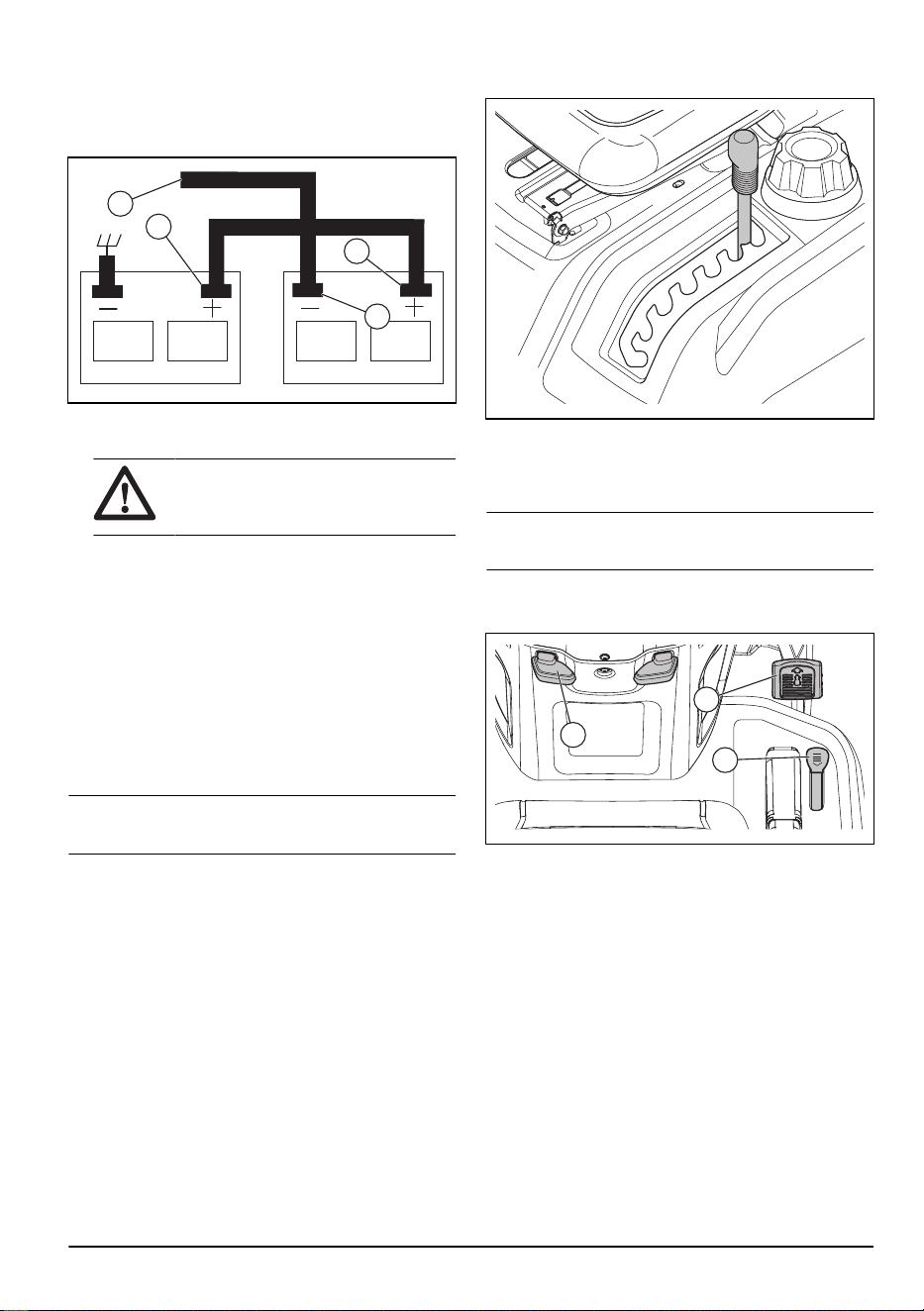
If the jumper cables are used for emergency starting,
follow the procedures below:
A
B
C
D
1. Connect one end of the RED cable to the POSITIVE
(+) terminal of each battery (B-C).
CAUTION: Be careful that a short
circuit does not occur against the
chassis of the product.
2. Connect one end of the BLACK cable to the
NEGATIVE (-) terminal (D) of a fully charged battery.
3. Connect the other end of the BLACK cable (A) to
good chassis ground, away from the fuel tank and
battery.
4. Remove the BLACK cable from the chassis when
the weak battery is fully charged.
5. Remove the BLACK cable from the fully charged
battery.
6. Remove the RED cable from the two batteries.
To remove the jumper cables
Note:
Remove the jumper cables in the opposite
sequence to how you connect them.
1. Remove the BLACK cable from the chassis.
2. Remove the BLACK cable from the fully charged
battery.
3. Remove the RED cable from the 2 batteries.
To set the cutting deck in transport
position or mow position
The cutting deck must be in transport position during
transportation.
• To set the product in transport position, pull the
cutting height lever in the direction of the seat and
put it in the highest cutting height position.
• To set the product in mow position, set the correct
cutting height. Refer to
To set the cutting height on
page 15
.
To set the cutting height
• Pull the lift lever in the direction of the seat and put it
in 1 of the notches for the correct cutting height.
To move forward and rearward
Note: The forward and reverse drive pedals go back
to neutral position when not pushed down.
The direction and speed of movement is controlled by
the forward and reverse drive pedals.
A
B
C
1. Start the engine and slowly release the parking
brake (A).
2. To start movement, slowly push the forward drive
pedal (B) or the reverse drive pedal (C) down.
3. Push the forward drive pedal (B) or the reverse drive
pedal (C) down more to increase speed.
To use the cruise control
Only use the cruise control for forward travel on smooth,
straight surfaces. The cruise control will disengage
automatically if the conditions for cruise control become
unsatisfactory.
2231 - 003 - 22.09.2023
15

1. Push the forward drive pedal (B) down. Keep the
forward drive pedal in a position that gives the
correct speed for the terrain.
A
B
2. Pull the cruise control lever (A) up and hold it while
you release the forward drive pedal.
3. Release the cruise control lever to engage the cruise
control.
4. Push the brake pedal or tap on the forward drive
pedal to disengage the cruise control.
To engage and disengage the parking
brake
1. To engage the parking brake, push down the brake
pedal (A) fully to the lowest position.
B
A
2. With the brake pedal pushed down, pull up the
parking brake lever (B).
3. Release the brake pedal.
4. Release the parking brake lever.
Note:
Make sure that the parking brake holds the
product safely.
5. To release the parking brake, push down the brake
pedal.
To stop the product
WARNING:
Always stop the product,
engage the parking brake and remove the
ignition key before you go away from the
product.
CAUTION: The exhaust gas from the
warm engine can cause burn damage to
the grass. To prevent burn damage , to the
grass, always stop the engine when you
stop the product on grass areas.
1. Push down on the brake pedal (A) fully until the
product stops fully.
A
2. Disengage the cutting deck. Refer to
To engage and
disengage the cutting deck on page 17
.
3. Put the throttle control in the slow position and let the
engine operate at idle speed for some minutes.
4. Put the cutting deck in the transport position. Refer
to
To set the cutting deck in transport position or
mow position on page 15
.
5. Turn the ignition key to the "STOP" position and
remove the ignition key from the ignition.
To use the throttle control
The operating efficiency of the engine decreases when
the engine operates at less than full speed. Full speed
gives the best mower performance.
• Set the throttle control (A) to the "FULL" position to
operate the engine at full speed.
A
16
2231 - 003 - 22.09.2023

To use the choke control
Note: Use the choke control to start a cold engine. Do
not use the choke control to start a warm engine.
A
1. Pull the knob (A) out to engage the choke control.
2. Push the knob (A) slowly to disengage the choke
control.
To use the differential lock control
Note: The product or system is not damaged if the
differential lock is engaged for a long period of time.
CAUTION: Do not engage the
differential lock while the product moves.
Note: If the differential lock (A) is engaged when you
turn, the grass can be moved or turfed.
1. Stop the product and push the differential lock switch
to the "ON" position.
2. Move the product forward. As the rear tires turn, the
differential lock engages.
To disengage the differential lock:
• Push the differential lock switch to the "OFF"
position.
Note:
If the differential lock does not disengage, steer
the product from side to side.
A
To use the headlight
• Push the power switch to position (A) to make the
headlight come on.
A
B
• Push the power switch to position (B) to make the
headlight go off.
To engage and disengage the cutting
deck
WARNING: Do not operate the cutting
deck without a deflector installed to the
grass discharge.
The product has an operator presence control (OPC).
When you go away from the seat with the engine on and
the cutting deck engaged, the engine stops.
Stay fully and in the center of the seat to make sure
that the engine operates correctly and does not stop on
rough terrain or hills.
• Pull the PTO button up to engage the cutting deck.
• Push the PTO button down to disengage the cutting
deck.
To use the reverse operation system
(ROS)
Note:
If you try to go rearward with the product
when the cutting deck is engaged, the engine stops
immediately. Engage the ROS to go rearward with the
product when the cutting deck is engaged.
2231 - 003 - 22.09.2023 17
WARNING: Before and while you
operate the product rearward, look down
and behind the product for the safety of
others.
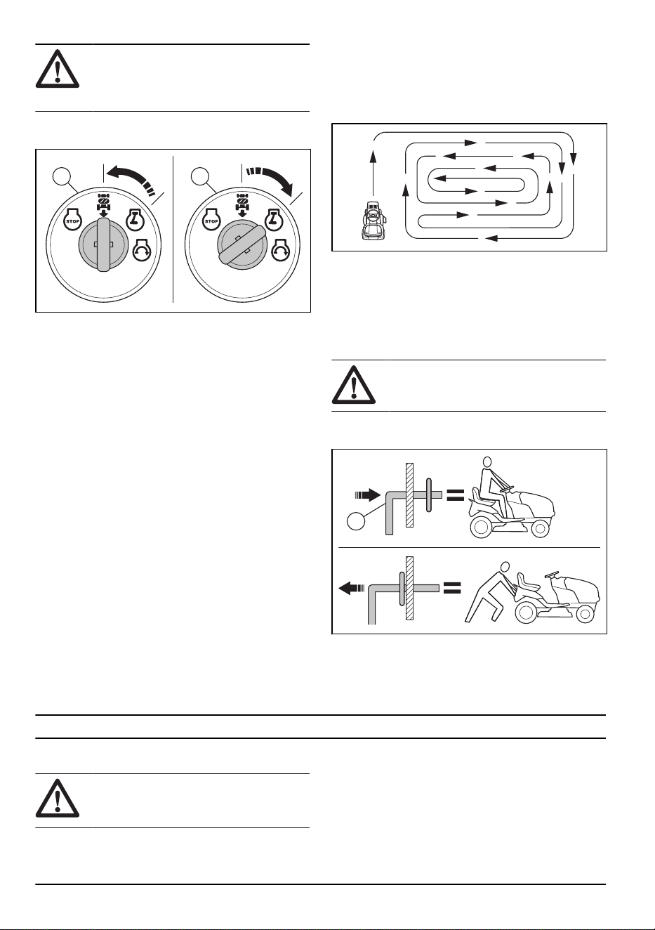
1. Turn the ignition key counterclockwise to the ROS
"ON" position (A) to engage the ROS.
BA
2. Slowly push down the reverse drive pedal to start
movement.
3. Turn the ignition key clockwise to the engine "ON"
position (B) to disengage the ROS.
To get a good cutting result
• For best performance, do maintenance on the
product regularly as given in the maintenance
schedule. Refer to
Maintenance schedule on page
19
.
• Do not cut a wet lawn. Wet grass can give a bad
cutting result.
• Do not use tire chains when you attach the cutting
deck to the product.
• Make sure that the cutting deck is level. Refer to
To
adjust the parallelism of the cutting deck on page
26
.
• If the grass is high, start with a high cutting height
and decrease it gradually.
• Move the product forward at low speed if the grass is
high and thick.
• Use full throttle when you cut the grass.
• Cut the grass in an irregular pattern.
• Use the left side of the cutting deck when you
cut near trees, bushes or paths. The blade cuts
approximately 15 mm in from the side of the cutting
deck.
• When you cut large areas, move the product to the
right during 1 or 2 turns around the work area. This
procedure will keep the grass discharge away from
shrubs, fences and driveways. After approximately
2 turns around the work area, cut in the opposite
direction.
• To get the best cutting result, cut the grass
frequently.
To put the product in freewheel mode
If it is necessary to move or tow the product without aid
from the engine, you must put the product in freewheel
mode.
WARNING: Do not put the product in
freewheel mode on a slope.
• Push in the freewheel control lever (A) to put the
product in drive mode.
A
• Pull out the freewheel control lever to put the product
in freewheel mode.
Maintenance
Introduction
WARNING: Read and understand the
safety chapter before you do maintenance
on the product.
18 2231 - 003 - 22.09.2023

Maintenance schedule
Maintenance schedule Before
each
use
At inter-
vals of 8
hours
At inter-
vals of
25 hours
At inter-
vals of
50 hours
At inter-
vals of
100
hours
Each
season
Before
storage
Product Do a check of the brake
function.
X X
Do a check of tire pres-
sure.
X X
Do a check of the op-
erator presence control
(OPC).
X
Do a check of the reverse
operation system (ROS).
X
Do a check for loose fas-
teners.
X X X
Examine the blades for
wear and damage.
X
2
Lubricate the product. Re-
fer to
Lubrication sched-
ule on page 20
.
X X
Do a check of the battery
level.
X
Clean the battery and the
terminals.
X X
Clean pieces off the
steering plate. Refer to
To
clean the product on page
21
.
X
Do a check of the trans-
axle cooling fan.
X
Make sure that the cutting
deck is level.
X
Do a check of the V-belts. X
2
Examine the blades more frequently if you cut where there is sand and soil.
2231 - 003 - 22.09.2023 19

Maintenance schedule Before
each
use
At inter-
vals of 8
hours
At inter-
vals of
25 hours
At inter-
vals of
50 hours
At inter-
vals of
100
hours
Each
season
Before
storage
Engine Do a check of the engine
oil level.
X X
Change the engine oil
(models with oil filter).
X
1
X
Change the engine oil
(models without oil filter).
X
1
X
Clean the air filter. X
3
Clean the air screen. X
3
Do an inspection of the
muffler and the spark ar-
rester.
X
Replace the oil filter (if it
is equipped).
X
1
X
Clean the engine cooling
fins.
X
3
Replace the spark plug. X X
Replace the paper car-
tridge of the air filter.
X
3
Replace the fuel filter X
Do a check of the muffler.
Refer to
To do a check of
the muffler on page 31
.
X
Lubrication schedule
CAUTION: Do not lubricate the pivot
points that have special nylon bearings.
Tacky lubricants can attach dirt. The dirt
decreases the life of the special nylon
bearings. If it is necessary to lubricate the
nylon bearings, use only a small quantity of
dry type lubricant.
1
Do more frequently if you operate with a heavy load, in high ambient temperatures, or in dirty conditions.
1
Do more frequently if you operate with a heavy load, in high ambient temperatures, or in dirty conditions.
3
Do more frequently if you operate with in dirty conditions.
3
Do more frequently if you operate with in dirty conditions.
1
Do more frequently if you operate with a heavy load, in high ambient temperatures, or in dirty conditions.
3
Do more frequently if you operate with in dirty conditions.
3
Do more frequently if you operate with in dirty conditions.
20 2231 - 003 - 22.09.2023
A
A
B
A
A
A
A. General lubrication. Lubricate the spindle grease
connection, front wheel bearing, gear teeth of the
steering part.
B. Engine lubrication. Refer to
To lubricate the engine
on page 29
.
Tractor
To clean the product
Do not use a garden hose or a pressure washer to clean
the surface except for the washout port. Keep water out
of the engine and transmission. Water in the engine or
transmission can decrease the life of the product. Use
compressed air or a leaf blower to remove grass, leaves
and litter.
• Clean all unwanted material from the engine, battery,
seat and other parts of the product.
• Clean contamination from the steering plate.
Contamination limits the movement of the clutch/
brake pedal shaft, causes the belt to loosen and
decreases forward movement.
CAUTION:
Avoid all pinch points
and movable parts.
• Keep the surfaces and wheels free of all gasoline,
oil, and so on.
• Use automotive type wax to prevent damage to the
surfaces.
To use the deck washout port
WARNING: Install bolts and locknuts in
all holes in the cutting deck.
WARNING: Replace the broken or
missing washout fitting immediately before
you use the cutting deck.
WARNING: A broken or missing
washout port can cause injury to you or
others by thrown objects.
The product has a washout port as a part of the deck
washout system. Use it after each operation.
1. Move the product to a level, clear area near a
garden hose connected to a water outlet.
CAUTION: Make sure the discharge
chute is far away from buildings, parked
vehicles and other items of value.
Remove the collector chute or mulch
cover if necessary.
2. Make sure the attachment clutch control is in the
“DISENGAGED” position.
3. Stop the engine and engage the parking brake.
4. Put the nozzle adapter (A) onto the end of the
garden hose (B).
A
C
B
5. Connect the nozzle adapter on the washout port (C)
on the left side of the cutting deck.
CAUTION:
Pull the garden hose to
make sure that the nozzle adapter is fully
connected to the deck washout port.
6. Start the water supply.
7. Start the engine and put the throttle control in the
fast position.
CAUTION:
Make sure the area is
clear and that there are no children in
the area when you clean the cutting
deck.
8. Sit in the seat and engage the cutting deck. Let the
cutting deck operate until it is clean.
9. Disengage the cutting deck and stop the engine.
10. Stop the water supply.
11. Disconnect the garden hose and nozzle adapter
from the deck washout port.
12. Move the product to a dry area.
13. Engage the cutting deck and let it operate until it is
dry.
2231 - 003 - 22.09.2023
21
To adjust the throttle control cable
The throttle control is set at the factory and adjustment
should not be necessary. If an adjustment is necessary,
see the Engine manual.
To adjust the choke control
The choke control is set at the factory and adjustment
should not be necessary. If an adjustment is necessary,
see the Engine manual.
To examine the interlocks and the relays
Note: Loose or damaged wires can make your
product run unsatisfactorily, stop running or prevent it
from starting.
• Examine the wires.
To replace the headlight LED light
1. Open the engine cover.
2. Disconnect the wire harness from the LED light.
3. Remove the screws, the LED light, the reflector and
the lens.
4. Install a new LED light.
5. Install the reflector and the lens with the screws.
6. Connect the wire harness to the LED light.
7. Close the engine cover.
To do a check of the tires
Note:
To seal the tire holes and prevent flat tires
because of slow leaks, purchase sealant from your local
parts dealer. Tire sealant also prevents tire dry rot and
corrosion.
• Make sure the air pressure in all tires is correct (See
the sides of tires for correct PSI).
• Keep the tires free of gasoline, oil or insect control
chemicals that can cause damage to the rubber.
• Keep the tires away from stumps, stones, rut pits,
sharp objects and other dangerous objects that may
cause tire damage.
To repair the tires
1. Lift the front axle and support it safely.
CAUTION:
Lift and support one axle
at a time.
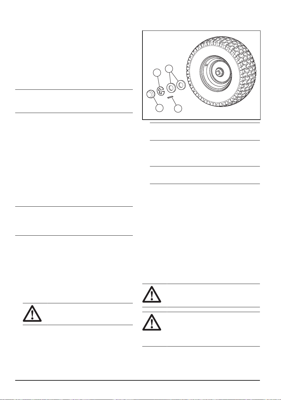
2. Remove the dust cover (A), the E-clip (B), the
washer (C) and the square key (D).
B
C
A
D
Note: There are square keys on the rear wheels
only.
3. Remove the wheel from the axle.
4. Remove the tire from the wheel.
5. Repair the tire.
Note: Use tire sealant to seal holes in the tire. Tire
sealant also prevents tire dry rot and corrosion.
6. Install the tire on the wheel.
7. Install the wheel, the washer, the square key, and
the E-clip on the axle. Make sure that the E-clip is
installed correctly in the groove on the axle.
8. Install the dust cover.
To examine the V-belts
The belts are not adjustable.
• Examine the V-belts for deterioration and wear after
each interval of 100 hours of operation.
• Replace the V-belts if they start to move because
they are too worn.
To do maintenance on the transaxle cooling
fan
CAUTION:
Do not clean the fan or the
transmission while the engine is on or while
the transmission is hot.
CAUTION: Do not use a high-pressure
washer or a steam cleaner. Water can go
into bearings and electrical connections and
cause corrosion which causes damage to
the product.
To keep the transmission cool, keep the transmission
fan and cooling fins clean.
22
2231 - 003 - 22.09.2023
• Before you clean with water, clean with a brush.
Remove grass cuttings and dirt on and around the
transaxle fan and cooling fins.
• Examine the cooling fan to make sure the fan blades
are clean and not damaged.
To examine the transaxle pump fluid
• Make sure that the transaxle pump fluid does not
leak.
• Speak to the nearest approved service center or
department if the transaxle pump fluid leaks.
To adjust the front wheel toe-in and camber
The front wheel toe-in and camber is correctly set at
the factory. The front wheel toe-in and camber are not
adjustable.
• Speak to an approved service center if the factory-
set front wheel toe-in or camber is damaged.
To replace the fuse
This product has an automotive-type fuse. The fuse
holder is located behind the dashboard.
1. Hold the fuse holder and pull the blown fuse out.
2. Put a new fuse in the fuse holder.
To remove and install the engine cover and
the grill assembly
A
1. Lift the engine cover.
2. Disconnect the headlight wire connector (A).
3. Stay in front of the tractor. Hold the engine cover on
its sides. Tilt the engine cover in the direction of the
engine and lift it to remove it from the product.
4. Install in the opposite sequence.
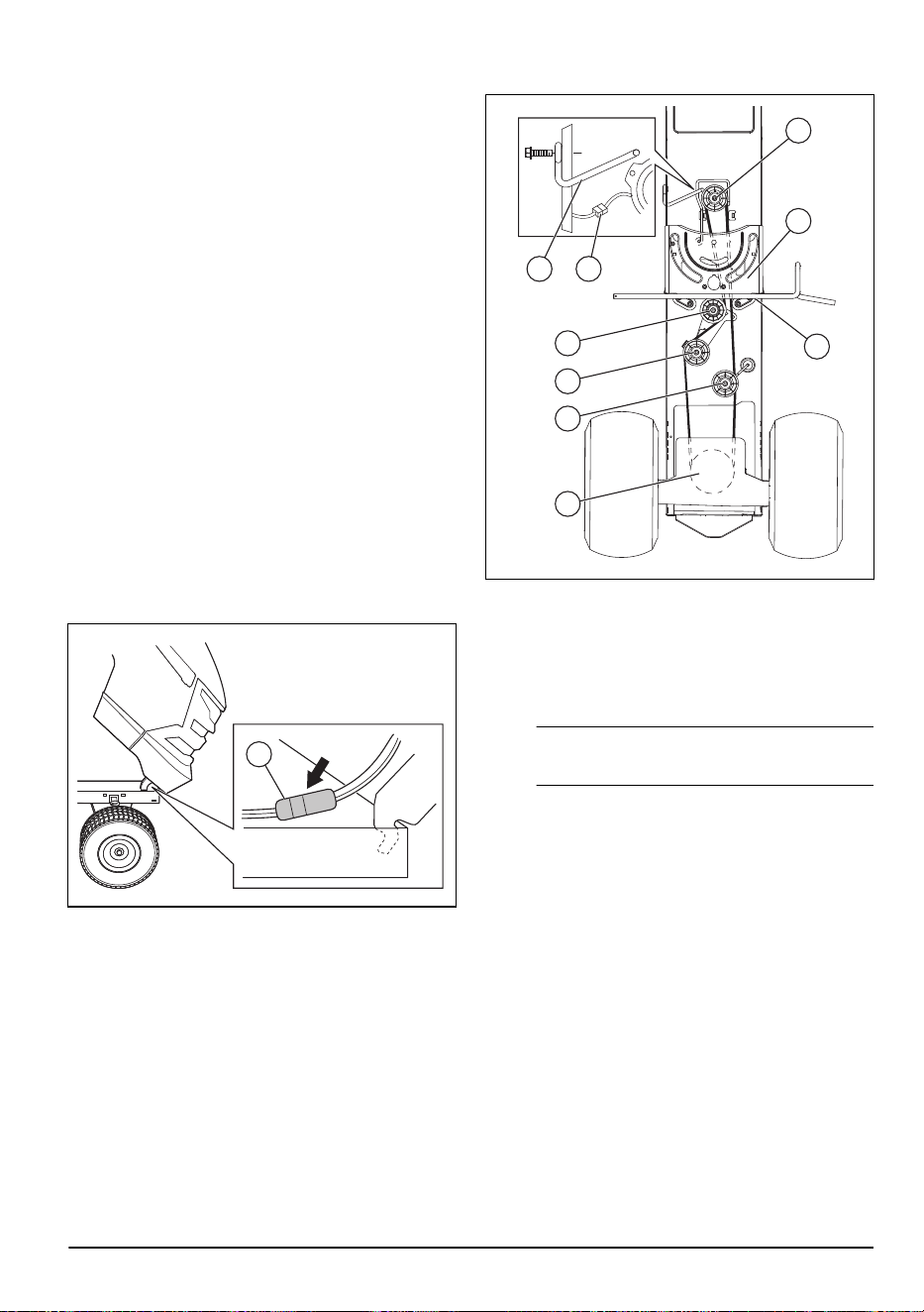
To replace the motion drive belt
G
H
I
F
E
D
C
AB
Park the product on a level surface. Engage the parking
brake. Refer to the belt installation decal on the bottom
side of the left footrest.
1. Remove the belt.
a) Remove the mower. See
To remove and install
the cutting deck on page 25
.
Note:
Be careful with the motion drive belt and
the position of the belt guides and keepers.
b) Disconnect the clutch wire harness (A).
c) Remove the anti-rotation link (B) on the right side
of the product.
d) Remove the belt from the stationary idler (C) and
clutching idler (D).
e) Remove the belt from the centerspan idler (E).
f) Pull the belt to the rear part of the product.
Carefully remove the belt from the transmission
input pulley and above the cooling fan blades (F).
g) Remove the belt from the engine pulley and
around the electrical clutch (G).
h) Move the belt to the rear part of the product
and off the steering plate (H). Remove from the
product.
2. Install the new belt from the rear part of the product
to the front, and above the steering plate (H) and
clutch brake pedal shaft (I).
a) Pull the belt to the front of the product and install
the belt around the electrical clutch and onto
engine pulley (G).
b) Pull the belt to the rear part of the product.
2231 - 003 - 22.09.2023
23

c) Carefully install the belt below around the
transmission cooling fan and onto the input
pulley (F). Make sure the belt is in the belt
keeper.
d) Install the belt on the centerspan idler (E).
e) Install the belt through the stationary idler (C)
and clutching idler (D).
f) Install the anti-rotation link (B) on the right side of
the product and tighten fully.
g) Connect the clutch harness (A).
h) Make sure the belt is in all pulley grooves and in
all belt guides and keepers.
i) Install the mower. See
To remove and install the
cutting deck on page 25
Battery
To clean the battery and the terminals
Corrosion and dirt on the battery and terminals can
cause the battery to drain power.
1. Remove the terminal guard.
2. Disconnect the BLACK battery cable.
3. Disconnect the RED battery cable and remove the
battery from the product.
4. Spray the battery with water and let dry.
5. Clean the terminals and battery cable ends with a
wire brush.
6. Lubricate the terminals with grease or equivalent.
7. Install the battery. Refer to
To connect the battery on
page 12
.
To replace the battery
WARNING:
Do not short the battery
terminals. Do not let tools or other objects
touch the two terminals at the same time.
WARNING: Before you connect the
battery, remove your metal bracelets,
wristwatch bands, rings, and so on.
1. Lift the hood to a raised position.
2. Remove the terminal cover (C).
3. Disconnect the black (negative) ground cable (A) by
removing the bolt and nut.
WARNING:
The black cable
(negative) terminal must be
disconnected first.
4. Disconnect the red (positive) battery cable (B).
5. Carefully remove the battery from the product.
6. Install a new battery in the same position as the old
battery.
7. Install the terminal cover (C).
8. Connect the red (positive) battery cable (B) and
tighten the bolt and nut.
WARNING: The red cable (positive)
terminal must be connected first
to prevent sparks from accidental
grounding.
9. Connect the black (negative) cable (A) and tighten
the bolt and nut.
10. Lower the hood.
A
C
B
To connect the jumper cables
WARNING:
Risk of explosion because
of explosive gas that comes from the
battery. Do not connect the negative
terminal of the charged battery to or near the
negative terminal of the weak battery.
CAUTION: Do not use the battery of
your product to start other vehicles.
24 2231 - 003 - 22.09.2023
1. Connect one end of the red battery cable to the
POSITIVE (+) battery terminal (A) on the weak
battery.
B
A
C
D
2. Connect the other end of the red battery cable to the
POSITIVE (+) battery terminal (B) on the charged
battery.
WARNING: Do not let the ends of
the red battery cable touch the chassis.
This will cause a short circuit.
3. Connect one end of the black battery cable to the
NEGATIVE (-) battery terminal (C) on the charged
battery.
4. Connect the other end of the black battery cable to
a CHASSIS GROUND (D), away from the fuel tank
and the battery.
To remove the jumper cables
Note: Remove the jumper cables in the opposite
sequence to how you connect them.
1. Remove the BLACK cable from the chassis.
2. Remove the BLACK cable from the fully charged
battery.
3. Remove the RED cable from the 2 batteries.
Cutting deck
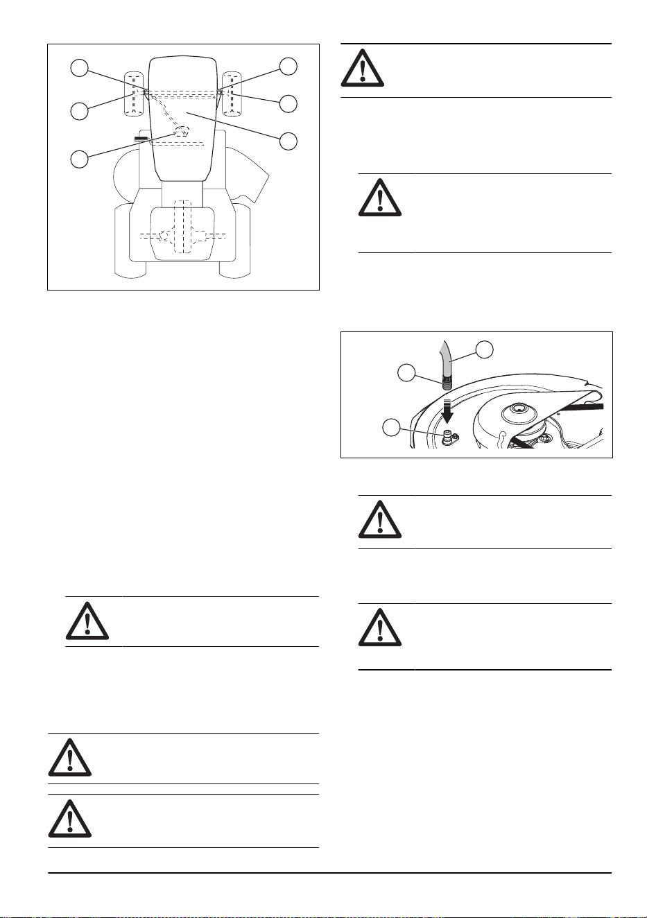
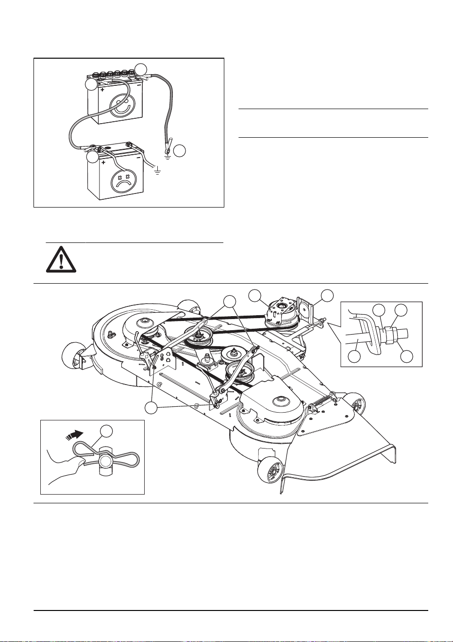
To remove and install the cutting deck
A
G
H
I
E B
F
D C
1. Park the product on a level surface and engage the
parking brake.
2. Disengage the cutting deck and stop the engine.
3. Put the attachment lift lever in the lowest position.
4. Remove the the drive belt for the cutting deck from
the electric clutch pulley (A).
5. Remove the lock nut (B), the nut (C), the bushing (D)
and disconnect the front link (E) from the bracket (F)
on the chassis.
6. Remove the clips (G) and the washers and
disconnect the 2 suspension arms (H) from the
chassis.
7. Remove the clips and the washers and disconnect
the rear lift links (I) from the cutting deck.
2231 - 003 - 22.09.2023 25
WARNING: When the rear lift links
are disconnected from the cutting deck,
the attachment lift lever is spring loaded.
Hold the attachment lift lever tightly if
you change its position.
8. Remove the cutting deck from the product.
9. Install the cutting deck in the opposite sequence.
Make sure that the discharge side is on the right
side of the product. Make sure that the drive belt
for the cutting deck is installed correctly. Refer to
To
remove the drive belt for the cutting deck on page
28
.
Note: The suspension arms must be in forward
position when you move the cutting deck below the
product.
To install the anti-sway bar
1. From the right side of the cutting deck, put the 90°
end of the anti-sway bar (A) into the hole in the
transaxle bracket (B).
A
B
D
E
C
2. Put the integrated washer end (C) of the anti-sway
bar into the hole in the rear bracket on the right side
of the cutting deck. Move the cutting deck if it is
necessary.
3. Install the washer (D) and the clip (E).
To adjust the parallelism of the cutting deck
To do a visual side to side adjustment of the cutting
deck
If the cutting height is not the same on the right and left
side of the product, the cutting height can be adjusted.
Adjust the cutting height on the side of cutting deck that
has the lower cutting height.
1. Make sure that the tires are fully inflated.
2. Park the product on a level surface.
3. Go to the side of cutting deck that has the lower
cutting height.
Note:
Some models only have left side
adjustment.
4. Adjust the cutting height with a 3/4" wrench.
A
Note: Each full turn of lift adjustment nut changes
the cutting deck height 3/16" (4.7 mm).
a) Turn the lift adjustment nut (A) to the left to lower
the cutting deck.
b) Turn the lift adjustment nut (A) to the right to lift
the cutting deck.
5. Cut some grass and examine the results. Adjust if it
is necessary.
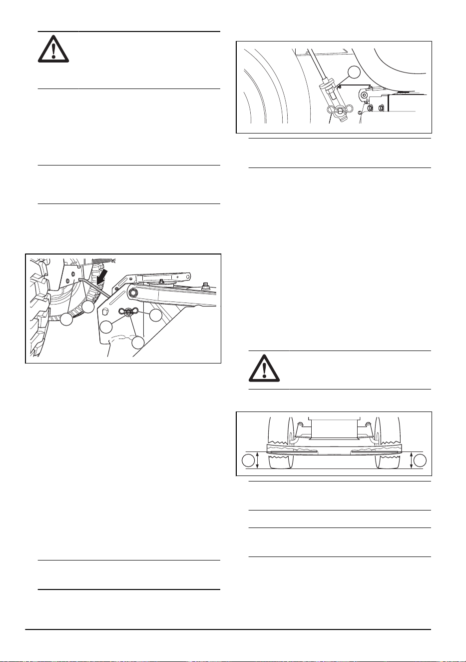
To do a precision side to side adjustment of the cutting
deck
1. Make sure that the tires are fully inflated.
2. Park the product on a level surface.
3. Put the cutting deck in the transport position. Refer
to
To set the cutting deck in transport position or
mow position on page 15
.
4. Turn the outer blade tips to align with the cutting
deck side to side.
WARNING:
The blades on the
cutting deck are sharp and can cause
injury. Use protective gloves.
5. Measure the distance (B) from the bottom edge of
the blade to the ground on the left and right side.
B B
Note:
The distance must be the same on the 2
sides.
6. Adjust the cutting height with a 3/4 in wrench.
Note:
Each full turn of the lift adjustment nut
changes the cutting height with 3/16 in (4.7 mm).
26 2231 - 003 - 22.09.2023
a) Turn the lift adjustment nut (A) to the left to lower
the cutting deck.
A
b) Turn the lift adjustment nut (A) to the right to lift
the cutting deck.
7. Measure the distance again. Adjust until the 2 sides
are equal.
8. Cut some grass and examine the results. Adjust if it
is necessary.
To do a front to rear adjustment of the cutting deck
The cutting deck must be level side to side before you
do front to rear adjustment. Refer to
To do a visual side
to side adjustment of the cutting deck on page 26
.
1. Make sure that the tires are fully inflated.
2. Park the product on a level surface.
3. Put the cutting deck in transport position. Refer to
To set the cutting deck in transport position or mow
position on page 15
.
4. Turn the blades until they point straight forward.
WARNING:
The blades on the
cutting deck are sharp and can cause
injury. Use protective gloves.
5. Measure the distance to the ground at the rear (A)
and front (B) end of the blade.
BA
Note:
To get the best cutting results, the blades
must be adjusted until the front end is 1/8–1/2 in
(3.1–12.7 mm) lower than the rear end when the
cutting deck is in the highest position.
6. Go to the front of the product to make an adjustment.
7. Use a 11/16 in wrench to loosen the jam nut (C) to
clear the lift adjustment nut (D).
D
C
8. Adjust the cutting deck height with a 3/4 in wrench.
Note: Each full turn of the lift adjustment nut
changes the cutting deck height 1/8 in (3.1 mm).
a) Turn the lift adjustment nut counterclockwise to
lower the cutting deck.
b) Turn the lift adjustment nut clockwise to lift the
cutting deck.
9. Measure the front and rear distance again.
10. Adjust until the front end of the blade is 1/8–1/2 in
(3.1–12.7 mm) lower than the rear end.
11. Hold the lift adjustment nut in position with the
wrench and tighten the jam nut.
To replace the blades
For the best results, keep the mower blades sharp.
Replace bent or damaged blades.
WARNING:
The blades on the cutting
deck are sharp and can cause injury. Use
protective gloves.
CAUTION: Use only a replacement
blade approved by the manufacturer. It is
dangerous to use a blade not approved by
the manufacturer of the product. This can
cause damage to the product and void your
warranty.
1. Put the cutting deck in transport position. Refer to
To set the cutting deck in transport position or mow
position on page 15
.
2231 - 003 - 22.09.2023
27
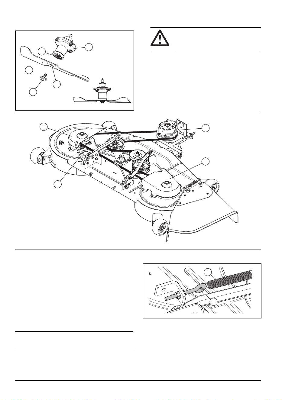
2. Remove the bolt (A) by turning it counterclockwise
and remove the blade (B).
A
D
C
E
B
3. Install the new or sharpened blade and the bolt.
CAUTION: The center hole (C) in
the blade must align with the star (D) on
the mandrel assembly (E).
4. Torque the bolt to 45–55 ft-lbs (62-75 Nm).
To remove the drive belt for the cutting deck
A
C
B
D
1. Park the product on a level surface and engage the
parking brake.
2. Put the attachment lift lever in the lowest position.
3. Remove the mandrel covers (A) and (B).
4. Remove dirt and grass clippings around mandrels
and from the top surface of the deck.
5. Turn the pulleys with your hand and pull the belt (C)
to remove it from the groove in the pulleys.
6. Remove the belt from around the electrical clutch (D)
on the engine shaft.
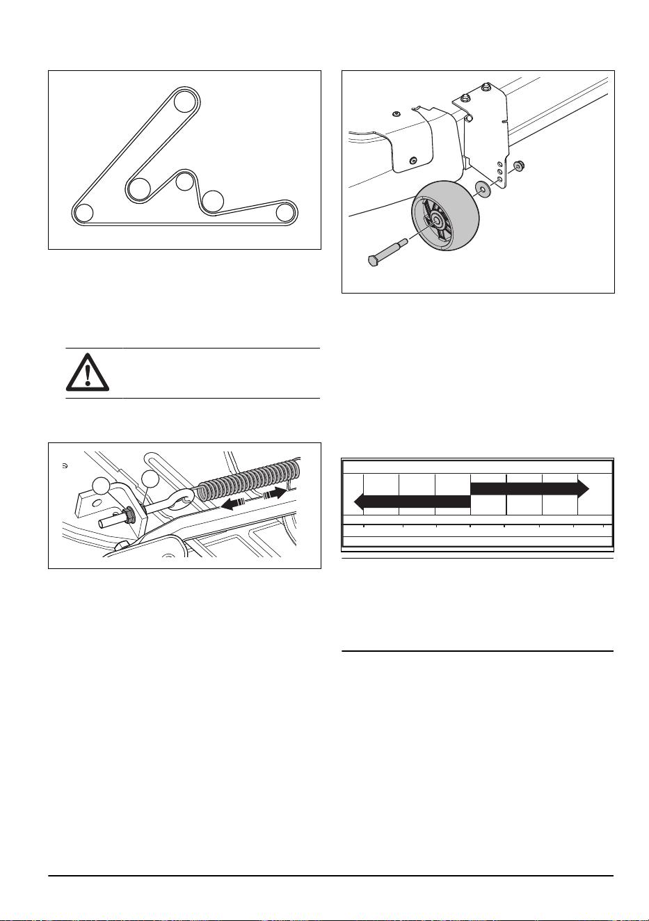
To install the drive belt for the cutting deck
Note: To easily install the drive belt for the cutting
deck, refer to the routing decal on the cutting deck.
1. Make sure the deck spring (A) is attached to the eye
bolt (B) on the idler arm.
A
B
28 2231 - 003 - 22.09.2023
2. Put the belt around all pulleys except the left side
mandrel pulley.
3. Install the belt from the rear part of the left side
mandrel pulley.
4. Rotate the left side mandrel pulley to pull the belt
into the groove on the left side mandrel pulley.
5. Refer to the routing decal on the cutting deck to
make sure that the belt is installed correctly.
CAUTION: Make sure that the belt
is not twisted.
6. Adjust the belt tension until the deck spring is
extended to a length of 5.1 in. (12.95 cm) in the
lowest cutting height.
D
C
a) Loosen the inner adjustment nut (C).
b) Turn the outer adjustment nut (D) clockwise
to increase the tension or counterclockwise to
decrease the tension.
c) When the tension is correct, tighten the inner
adjustment nut fully.
7. Install the madrel covers.
To adjust the anti-scalp rollers
The anti-scalp rollers keep the cutting deck in the
correct position on the ground and prevent lawn scalping
in most terrain conditions. The anti-scalp rollers are
adjusted correctly when they are slightly off the ground
when the cutting deck is at the necessary cutting height.
1. Park the product on a level surface and stop the
engine.
2. Adjust the product to the necessary cutting height.
Refer to
To set the cutting height on page 15
.
3. Remove the nut, the bolt, the washer, and the anti-
scalp roller.
4. Install the anti-scalp roller, the bolt, the washer, and
the nut in the correct position.
5. Adjust all anti-scalp rollers and install them in the
same procedure.
Engine
To lubricate the engine
Only use high quality detergent oil rated with API service
classification SJ-SN. The oil’s SAE viscosity grade
refers to the correct temperature for operation.
-20 0 30 40
80
100
-30
-20 0
20 30 40
F
C
32
-10
10
60
5W-30
SAE 30
Note: Multi-viscosity oils (5W30, 10W30, and so on)
help the engine start easily in cold weather but causes
increased oil use when used in temperatures above
32°F/0°C. Do a check of your engine oil level frequently
to prevent possible engine damage caused by low oil
level.
• Change the oil after intervals of 50 hours of
operation. If the product is not used for 50 hours in a
year, change the oil at a minimum of 1 time a year.
• Do a check of the crankcase oil level before you
start the engine and after each eight (8) hours of
operation.
• Tighten the oil fill cap/dipstick each time you do a
check of the oil level.
To do a check of the engine oil level
The engine in the product is filled with engine oil for
ambient temperatures of more than 32° F (0° C). For
operation in ambient temperatures of less than 32° F (0°
2231 - 003 - 22.09.2023
29

C), use the correct engine oil to make the product easier
to start. Refer to .
1. Park the product in level ground.
2. Remove the oil fill cap and dipstick and clean it with
a cloth.
3. Put the dipstick into the oil fill tube. Do not turn the
oil fill cap onto the oil fill tube.
4. Remove the dipstick. Use the gauge on the dipstick
to examine the engine oil level. If necessary, fill
engine oil until the mark “FULL” on the dipstick is
reached. Do not fill too much engine oil.
ADD FULL
CAUTION - DO
01341
5. Put the dipstick into the oil fill tube. Make sure that
the oil fill cap is fully tightened.
Note: To replace the engine oil, Refer to
To replace
the engine oil on page 30
.
To remove the lower cover
1. Lift the engine cover.
2. Remove the fastener (A) from the lower cover (B).
B
A
D
C
3. Carefully lift the lower cover (B) to release the cover
tabs (C) for the slots that taper (D).
CAUTION:
Be careful when you
lift the lower cover, there is a risk of
damage to the lower cover tabs (C).
4. Remove the lower cover.
To install the lower cover
1. Install the lower cover (B).
2. Carefully push the lower cover (B) to attach it to the
cover tabs (C) in the slots that taper (D).
B
A
D
C
CAUTION: Be careful when you
attach the lower cover, there is a risk of
damage to the lower cover tabs (C).
3. Install the fastener (A) to the lower cover (B).
4. Lower the engine cover.
To replace the engine oil
If the engine is cold, start the engine for 1–2 minutes
before you drain the engine oil. This makes the engine
oil faster to drain.
Before the engine oil is replaced, find the correct oil
temperature range.
Note: All oil must follow the recommended API
service class SG-SL.
CAUTION: Make sure that no dirt goes
into the engine when you replace the engine
oil. Dirt can cause damage to the engine.
WARNING: The engine oil is very
hot directly after the engine stops. Let the
engine become cool before you drain the
engine oil. If you spill engine oil on your skin,
clean with soap and water.
1. Park the product on a level surface.
2. Remove the lower cover. Refer to
To remove the
lower cover on page 30
.
3. Remove the dipstick.
30
2231 - 003 - 22.09.2023

4. Install the oil drain tube (A) on the engine oil drain
valve (B).
A
B
5. Put a container below the engine to catch the engine
oil.
6. Turn the oil drain valve counterclockwise to open the
oil drain valve. Use a 10 mm wrench.
7. When all engine oil is drained, turn the oil drain valve
clockwise to close it. Use a 10 mm wrench.
8. Use the 10 mm wrench to carefully torque the oil
drain valve closed. Do not tighten too tightly.
CAUTION: Do not apply too much
torque when you tighten the oil drain
valve.
9. Remove the oil drain tube from the oil drain valve.
10. Fill the engine with new engine oil through the
dipstick tube. Fill slowly. Do not fill the engine with
too much engine oil. For the approximate capacity,
refer to
Technical data on page 39
.
11. Do a check of the engine oil level. Refer to
To do a
check of the engine oil level on page 29
.
12. Install the lower cover. Refer to
To install the lower
cover on page 30
.
To replace the engine oil filter
WARNING:
Use protective gloves. If
you spill engine oil on your body, clean with
soap and water.
1. Drain the engine oil from the oil tank. Refer to
To
replace the engine oil on page 30
.
2. Turn the engine oil filter counterclockwise to remove
it.
3. Lightly lubricate the rubber seal on the new oil filter
with new engine oil.
4. To install the new oil filter, turn it clockwise until
the rubber seal fits correctly, then tighten a half turn
more.
5. Fill the oil tank with new engine oil. Refer to
To
replace the engine oil on page 30
.
6. Start the engine and let it operate at idle speed for 3
minutes.
7. Stop the engine and make sure that there is no oil
leakage from the oil filter.
Note: If the there is oil leakage, tighten the oil filter
again.
8. Fill the oil tank with more engine oil to replace the
engine oil that the new oil filter has absorbed.
To clean the air filter
The engine will not run satisfactorily with a dirty air filter.
Clean the air filter more frequently in dusty conditions.
To clean the air screen
Note: The air screen must be kept free of dirt to
prevent engine damage caused by overheating.
• Clean the air screen with a wire brush or
compressed air to remove dirt.
To do maintenance on the engine cooling
system
Note: A blocked grass screen, dirty or full cooling fins,
and/or removed blower housing, and so on, can make
the engine too hot and cause engine damage.
• Make sure that the grass screen, the cooling fins,
and other external surfaces of the engine are clean
at all times.
• After each interval of 100 hours of operation (more
often in extremely dusty and dirty conditions),
remove the blower housing and other parts of the
engine cooling system. Clean the cooling fins and
external surfaces as necessary. Make sure that the
engine cooling system parts are installed correctly.
To do a check of the muffler
• Examine the muffler regularly to make sure that it is
attached correctly and not damaged.
To replace the spark plugs
The spark plug type and clearance (gap setting) are
shown in .
• Replace the spark plugs at the start of each cutting
season or after each interval of 100 hours of
operation.
To replace the in-line fuel filter
Note:
Replace the in-line fuel filter every year at
minimum.
Replace the in-line filter if it becomes clogged and stops
the flow of fuel to the carburetor.
2231 - 003 - 22.09.2023
31

1. Let the engine cool.
2. Remove the in-line fuel filter (B) and seal the fuel line
sections with plugs.
3. Put the new in-line fuel filter in position in the fuel
line with the arrow pointing to the carburetor.
4. Make sure that there are no fuel line leaks and that
the clamps (A) are in the correct position.
5. If you spill, immediately clean the product.
A
B
To remove the air from the
transmission
CAUTION: Do not engage or disengage
freewheel lever when the engine is in
operation.
To keep high performance, remove the air in the
transmission before you operate the product for the first
time.
If you replace the transmission, remove the air in the
new transmission before you operate the product.
1. Park the product on a level surface that is clear and
open.
2. Stop the engine and engage the parking brake.
3. Put the freewheel control in the disengaged position.
Refer to
Transportation on page 37
.
4. Start the engine. When the engine has started,
move the throttle control to the slow position and
disengage the parking brake.
5. Do the steps that follow 3 times.
Note: During this procedure, there can be
movement of the drive wheels.
a) Push the forward drive pedal to the full forward
position and keep it pushed down for 5 seconds
before you release it.
b) Push the reverse drive pedal to the full reverse
position and keep it pushed down for 5 seconds
before you release it.
6. Stop the engine and engage the parking brake.
7. Put the freewheel control in the engaged position.
Refer to
Transportation on page 37
.
8. Sit in the seat and start the engine. When the engine
has started, move the throttle control to the half
speed position.
9. Disengage the parking brake.
10. Operate the product forward for approximately 5
ft (1.5 m) then rearward for 5 ft (1.5 m). Do this
procedure 3 times.
32
2231 - 003 - 22.09.2023

Troubleshooting
Problem Cause Action
The engine does not start. There is no fuel in the fuel tank. Fill the fuel tank.
The throttle control is not in the cor-
rect position.
Refer to the start instructions.
The spark plug is damaged. Replace the spark plug.
The air filter is dirty. Clean or replace the air filter.
The fuel filter is clogged. Replace the fuel filter.
There is water in the fuel. Remove all fuel from the fuel tank
and the carburetor. Fill the fuel tank
with new fuel and replace the fuel fil-
ter.
The wires are loose or damaged. Do a check of all wires.
The engine valves are not adjusted
correctly.
Speak to an approved service agent.
The engine is flooded. Wait 2–3 minutes before you try to
start the engine again.
The fuel in the fuel tank is bad. Replace the fuel in the fuel tank.
The starter motor does not turn the
engine over.
The battery is too weak. Charge the battery.
The attachment clutch control is en-
gaged.
Disengage the attachment clutch
control.
The clutch/brake pedal is not pushed
down fully.
Push down the clutch/brake pedal
fully when you start the engine.
The connection at the cable connec-
tors on the battery terminals is bad.
Do a check of the battery connec-
tions.
The main fuse is damaged. Replace the main fuse.
The ignition lock is damaged. Speak to an approved service agent.
The safety connector for clutch/brake
pedal is damaged.
Speak to an approved service agent.
The starter motor or the solenoid is
damaged.
Speak to an approved service agent.
The operator presence control (OPC)
does not operate correctly.
Do a check of the wires, switches
and connections. If not corrected,
speak to an approved service agent.
Do not use a product with an oper-
ator presence control that does not
operate correctly.
2231 - 003 - 22.09.2023 33

Problem Cause Action
The engine does not run smoothly. The spark plug is damaged. Replace the spark plug.
The carburetor is not adjusted cor-
rectly.
Speak to an approved service agent.
The air filter is dirty. Clean or replace the air filter.
The check valve on the fuel tank cap
is damaged.
Replace the fuel tank cap.
The fuel tank is almost empty. Fill the fuel tank with fuel.
There is water in the fuel. Remove all fuel from the fuel tank
and the carburetor. Fill the fuel tank
with new fuel and replace the fuel fil-
ter.
The choke is engaged and the en-
gine is warm.
Disengage the choke.
The fuel mix or fuel type is incorrect. Remove all fuel from the fuel tank
and the carburetor. Fill the fuel tank
with the correct fuel mix or fuel type.
The fuel filter is clogged. Replace the fuel filter.
The spark plug is damaged. Replace the spark plug.
There is dirt in the carburetor or fuel
line.
Clean the carburetor and fuel lines.
The engine becomes too hot. There is overload in the engine. Decrease the workload.
The air intake or the cooling fins on
the engine are blocked.
Clean the air intake and the cooling
fins on the engine.
The cooling fan is damaged. Speak to an approved service agent.
The engine oil level is too low. Do a check of the engine oil level. Fill
with engine oil if it is necessary.
The ignition lock is damaged. Speak to an approved service agent.
The spark plug is damaged. Replace the spark plug.
34 2231 - 003 - 22.09.2023

Problem Cause Action
There is loss of power. The product is operated at too high
forward or rearward speed when you
cut grass.
Use slower speed.
The throttle control is in the choke
position.
Put the throttle control in the fast po-
sition.
There is build-up of grass, leaves or
unwanted material under the cutting
deck.
Clean the cutting deck.
The air filter is dirty. Clean or replace the air filter.
The engine oil level is too low. Do a check of the engine oil level. Fill
with engine oil if it is necessary.
The engine oil is dirty. Replace the engine oil.
The spark plug is damaged. Replace the spark plug.
The fuel filter is dirty. Replace the fuel filter.
The fuel in the fuel tank is bad. Replace the fuel in the fuel tank.
There is water in the fuel. Remove all fuel from the fuel tank
and the carburetor. Fill the fuel tank
with new fuel and replace the fuel fil-
ter.
The spark plug wire is loose. Connect and tighten the spark plug
wire.
The air intake or the cooling fins on
the engine are blocked.
Clean the air intake and the cooling
fins on the engine.
The muffler is clogged or damaged. Clean or replace the muffler.
There is loose or damaged wiring. Do a check of all wiring.
The engine valves are not adjusted
correctly.
Speak to an approved service agent.
There is vibration in the product. The blades are loose. Tighten bolts on the blades.
One or more of the blades are dam-
aged or not balanced.
Balance the blades or replace the
blades.
The engine is loose. Tighten the engine bolts.
The battery does not charge. The main fuse is damaged. Replace the main fuse.
The battery is damaged. Replace the battery.
The charging cable is disconnected. Connect the charging cable.
The connection at the cable connec-
tors on the battery terminals is bad.
Do a check of the battery connec-
tions.
The engine operates when the oper-
ator gets up from the seat when the
cutting deck is engaged. The operator presence control (OPC)
does not operate correctly.
Do a check of the wires, switches
and connections. If not corrected,
speak to an approved service agent.
Do not use a product with an oper-
ator presence control that does not
operate correctly.
2231 - 003 - 22.09.2023 35

Problem Cause Action
The blades cannot rotate. There is blockage in the clutch mech-
anism.
Remove the blockage.
The drive belt for the cutting deck is
worn or damaged.
Replace the drive belt for the cutting
deck.
An idler pulley is frozen. Replace the idler pulley.
A blade mandrel is frozen. Replace the blade mandrel.
Damaged grass discharge. The engine speed is too slow. Put the throttle control in the fast po-
sition.
The product is operated at too high
forward or rearward speed.
Use slower speed.
The grass is wet. Let the grass become dry before you
cut it.
The cutting deck is deck not parallel. Adjust the parallelism of the cutting
deck. Refer to
To adjust the parallel-
ism of the cutting deck on page 26
.
The tire pressure is incorrect. Do a check of the tire pressure. Ad-
just the tire pressure if it is necessa-
ry.
The blades are worn, damaged or
loose.
Replace blades or tighten bolts on
the blades.
Buildup of grass or dirt below the cut-
ting deck.
Clean the cutting deck.
The drive belt for the cutting deck is
worn or damaged.
Replace the drive belt for the cutting
deck.
The blades are incorrectly installed. Install the blades with the sharp edge
down.
Incorrect blades are used. Replace the blades with the correct
blades in the parts manual.
Clogged air holes of the cutting deck
from buildup of grass, dirt around
mandrels.
Clean around mandrels to open air
holes.
The headlight does not function. The headlight switch is in the off po-
sition.
Turn the headlight switch to the on
position.
The light bulb is damaged. Replace the light bulb.
The power switch for the headlight is
damaged.
Replace power switch for the head-
light.
The cable to the headlight is not con-
nected.
Do a check of wires and connections.
There is short-circuit in the headlight
cable.
Speak to an approved service agent.
36 2231 - 003 - 22.09.2023

Problem Cause Action
The product moves slowly, with irreg-
ular speed or not at all.
The product is in freewheel mode. Pull out the freewheel control lever.
Refer to
To put the product in free-
wheel mode on page 18
.
The parking brake is engaged. Disengage the parking brake.
The drive belt is loose or damaged. Replace drive belt.
There is air in the transmission. Remove the air from the transmis-
sion. Refer to
To remove the air from
the transmission on page 32
.
There is unwanted materials on the
steering plate (if the steering plate is
installed).
Clean the product.
The square key on the axle is miss-
ing.
Install the square key. Refer to
To
repair the tires on page 22
.
The cutting result is unsatisfactory. The blades are blunt or damaged. Sharpen the blades or replace the
blades.
The cutting deck is not parallel. Adjust the parallelism of the cutting
deck. Refer to
To adjust the parallel-
ism of the cutting deck on page 26
.
The grass is wet. Let the grass become dry before you
cut it.
The grass is long. Start with a high cutting height and
decrease it gradually.
The tire pressure is incorrect. Do a check of the tire pressure. Ad-
just the tire pressure if it is necessa-
ry.
The product is operated at too high
forward or rearward speed.
Use slower speed.
The drive belt for the cutting deck is
worn or damaged.
Replace the drive belt for the cutting
deck.
The engine backfires when the en-
gine stops.
The throttle control is not put in the
slow position.
Refer to
To stop the product on page
16
.
The engine stops when you try to re-
verse.
The reverse operation system (ROS)
is not engaged.
Engage the reverse operation system
(ROS). Refer to
To use the reverse
operation system (ROS) on page 17
.
Transportation, storage and disposal
Transportation
Note: Close and attach the hood to the product during
transportation to prevent damage. Connect the hood to
the product with the correct tools (rope, cord and so on).
2231 - 003 - 22.09.2023 37
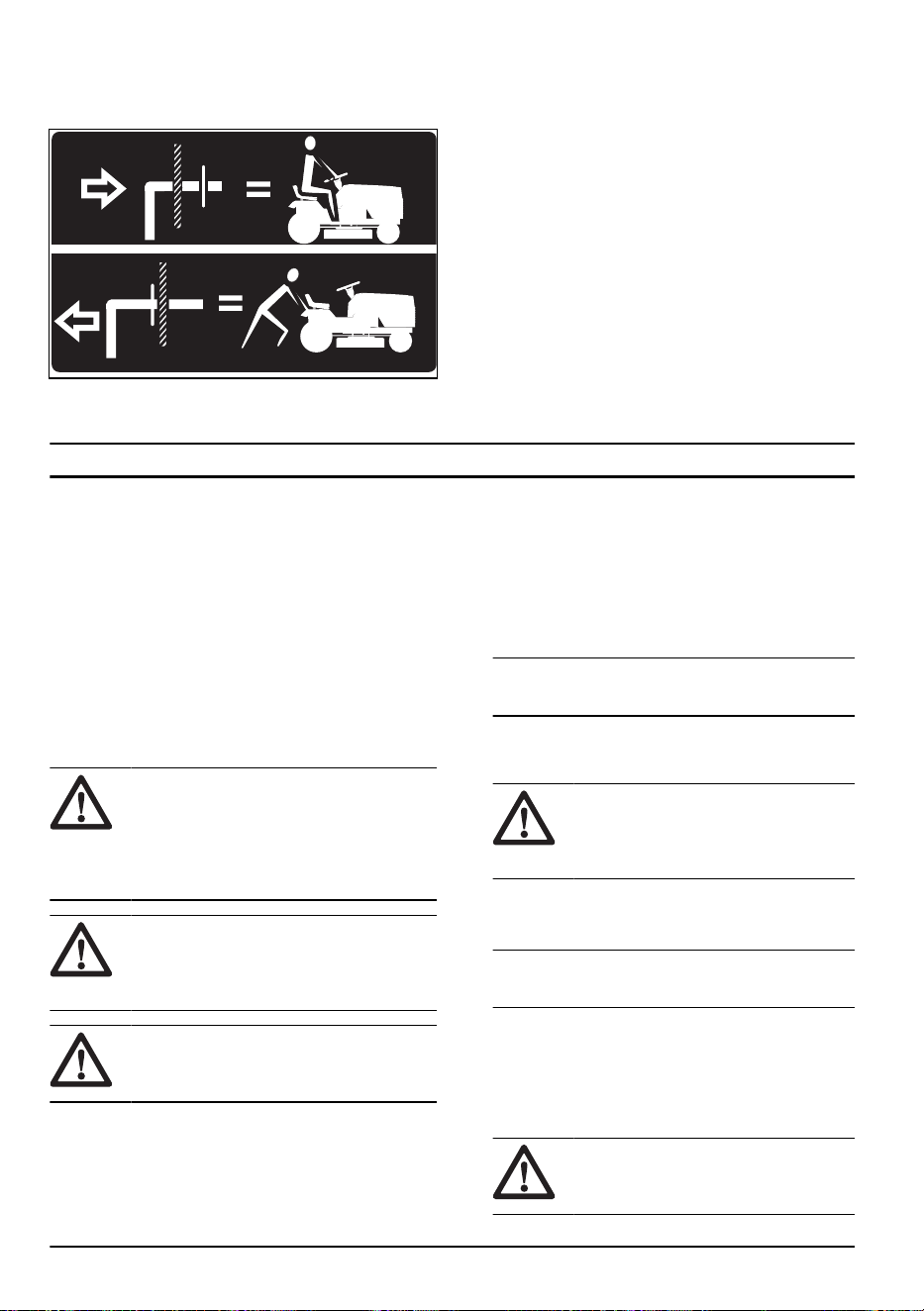
When you move the product, put the freewheel control
in freewheeling position to disengage the transmission.
Freewheel control is at the rear drawbar of the product.
1. Lift the attachment to the highest position with the
attachment lift control.
2. Pull the freewheel control out and into the slot and
release to hold it in the disengaged position.
3. Do not move the product at more than two (2) mph
(3.2 km/h).
4. To reengage transmission, reverse the above
procedure.
Tow safety
• Only use tow equipment approved by Husqvarna.
• Use the tow bar to attach the equipment.
• Do not tow equipment that is heavier than the
maximum permitted weight.
• Make sure that no other persons is near the product
when you tow equipment.
• Do not tow equipment on slopes or rough ground.
• Operate the product at low speed when you tow
equipment.
Storage
Prepare the product for storage at the end of the
season, and before more than 30 days of storage. If
you keep fuel in the fuel tank for 30 days or more, tacky
particles can cause blockage in the carburetor. This has
a negative effect on the engine function.
To prevent tacky particles during storage, add a
stabilizer. If alkylate gasoline is used, stabilizer is not
necessary. If you use standard gasoline, do not change
to alkylate gasoline. This can cause sensitive rubber
parts to become hard. Add stabilizer to the fuel in the
tank or in the container used for storage. Always use the
mixing ratios given by the manufacturer. Run the engine
for a minimum of 10 minutes after you add the stabilizer
until it flows into the carburetor.
WARNING: Do not keep the product
with fuel in the tank in an indoor location or
in locations with bad airflow. Risk of fire if
fuel fumes come near open flames, sparks,
or pilot lights in for example boilers, hot
water tanks and clothes dryers.
WARNING: Remove grass, leaves and
other flammable materials from the product
to decrease the risk of fire. Let the product
become cool before you put it in storage.
CAUTION: If you remove the battery
from the product, do not keep the battery
directly on concrete or damp surfaces.
• Clean the product, refer to
To clean the product on
page 21
.
• Repair paint damages to prevent corrosion.
• Examine the product for worn or damaged parts and
tighten loose screws and nuts.
• Examine the belts and replace them if they are worn
or damaged.
• If the product is put in storage for the winter, remove
and clean the cutting deck. Keep the cutting deck in
a clean and dry environment.
• Charge the battery fully.
Note: It can be necessary to charge the battery
again after a period of time in storage.
• Disconnect the battery and clean the terminals and
connectors. Refer to
To clean the battery and the
terminals on page 24
.
CAUTION: Risk of short circuit.
Make sure that you put the disconnected
battery cables in a position where they
cannot touch the battery or the terminals.
• Change the engine oil, and discard the waste oil.
• Empty the fuel tank. Start the engine and run it until
there is no remaining fuel in the carburetor.
Note: Do not empty the fuel tank and carburetor if
a stabilizer has been added.
• Remove the spark plugs and put about a tablespoon
of engine oil into each cylinder. Manually turn the
engine shaft to apply the oil. Install the spark plugs.
• Lubricate all grease nipples, joints and axles.
• Keep the product in a clean and dry area and put a
cover on it for more protection.
CAUTION:
Do not put a cover on
the product when the engine or exhaust
is warm.
38 2231 - 003 - 22.09.2023

• A cover for protection of your product during storage
or transport is available at your dealer.
Disposal
• Chemicals can be dangerous and must not be
discarded on the ground. Always discard used
chemicals at a service center or an applicable
disposal location.
• When the product is worn out, send it to the dealer
or to an applicable recycling location.
• Oil, oil filters, fuel and the battery can have negative
effects on the environment. Obey the local recycling
requirements and applicable regulations.
• Do not discard the battery as domestic waste.
• Send the battery to a Husqvarna service agent or
discard it at a disposal location for used batteries.
Technical data
TS 348XD
Engine
Engine brand Kawasaki
Engine model FR730V
Nominal engine output, HP / kW
1
24 / 17.9 @ 3400 rpm
Max. engine speed, rpm 3300 ± 100
Maximum speed forward, mph / km/h 5.5 / 8.9
Maximum speed reverse, mph / km/h 2.5 / 4
Fuel, minimum octane grade, lead-free, max 10% Etha-
nol and max 15% MTBE, AKI / RON
87 / 91
Fuel tank volume, gallons / l 4 / 15.14
Oil type above 32°F / 0°C (API: SJ-SN): SAE 10W30
Oil type below 32°F / 0°C (API: SJ-SN): SAE 5W30
Oil volume with oil filter, oz / l 68 / 2.1
Oil volume without oil filter, oz / l 61 / 1.8
Lubrication system Pressure with oil filter
Cooling system Air cooled
Air filter Dual
Alternator, V. amp. @ 3600 rpm 12 V 15 amp @ 3600 rpm
Start motor Electric start 12 V
Weight
Weight, with empty tanks, lb / kg 675 / 306
Cutting deck
Number of blades 3
1
The power rating as declared by the engine manufacturer is the average gross power output at the specified
RPM of a typical production engine for the engine model measured using SAE Standards for engine gross
power. Refer to the engine manufacturer engine specifications.
2231 - 003 - 22.09.2023 39

TS 348XD
Blade length, in. / cm 16.5 / 41.91
Cutting Width, in. / cm 48 / 122
Cutting Height, in. / cm 1.5-3.8 / 3.8-9.7
Tires
Tire pressure, rear – front, PSI / kPa / bar 15 / 103 / 1
Front tires, in. 16x6.5-8
Rear tires, turf pneumatic, in. 23x10.5-12
Brakes Mechanical parking brake
Electrical system
Type 12 V
Battery 28 A
Spark plug BPR4ES
Electrode gap, in. / mm 0.030 / 0.76
Spark plug torque, lb-ft / Nm 16 / 22
Service
Service
Do a yearly check at an authorized service center to
make sure that the product functions safely and at its
best during high season. The best time to do a servicing
or overhaul of the product is low season.
When you send an order for the spare parts, give
information about the purchase year, model, type, and
serial number.
Always use original spare parts.
40 2231 - 003 - 22.09.2023

Contenido
Introducción.................................................................. 41
Seguridad..................................................................... 44
Montaje......................................................................... 50
Funcionamiento............................................................ 53
Mantenimiento.............................................................. 59
Solución de problemas................................................. 75
Transporte, almacenamiento y eliminación de
residuos........................................................................ 81
Almacenamiento........................................................... 81
Eliminación................................................................... 82
Datos técnicos.............................................................. 82
Servicio......................................................................... 84
Anexo ...........................................................................85
Introducción
Inspección previa a la entrega y
números de producto
Tenga en cuenta: A este producto se le hizo
una inspección antes de la entrega. Asegúrese de
que su distribuidor le entregue una copia firmada del
documento de inspección previa a la entrega.
Información de contacto del ta-
ller de servicio:
Este manual de usuario pertenece al producto con el número de producto/número de serie:
/
Motor:
Transmisión:
Descripción del producto
Este es un tractor de césped con el equipo de corte
instalado entre los ejes delantero y trasero. Tiene un
motor de cuatro ciclos que utiliza gasolina.
Accesorios opcionales:
• Recogedor de césped
• Conector del mantillo
Uso previsto
Este producto solo se utiliza para cortar el césped en
jardines privados y en pendientes de jardines privados
no superiores a 15° de pendiente. No se debe utilizar
en parques públicos, campos de deporte ni en los
sectores agrícola o forestal. Utilice el producto solo con
accesorios aprobados por el fabricante.
Utilizar el producto de manera diferente es un uso
incorrecto. Anulará su garantía y se rechazará la
responsabilidad por daños al usuario de terceros en la
parte del fabricante.
Consulte las directivas locales para el funcionamiento
de los cortacéspedes.
Soporte/ayuda
Si necesita asistencia o tiene alguna pregunta acerca de
la aplicación, operación, mantenimiento o piezas de su
producto:
• Visite nuestro sitio web: www.husqvarna.com
• Llámenos de manera gratuita: 1-800-487-5951
2231 - 003 - 22.09.2023 41
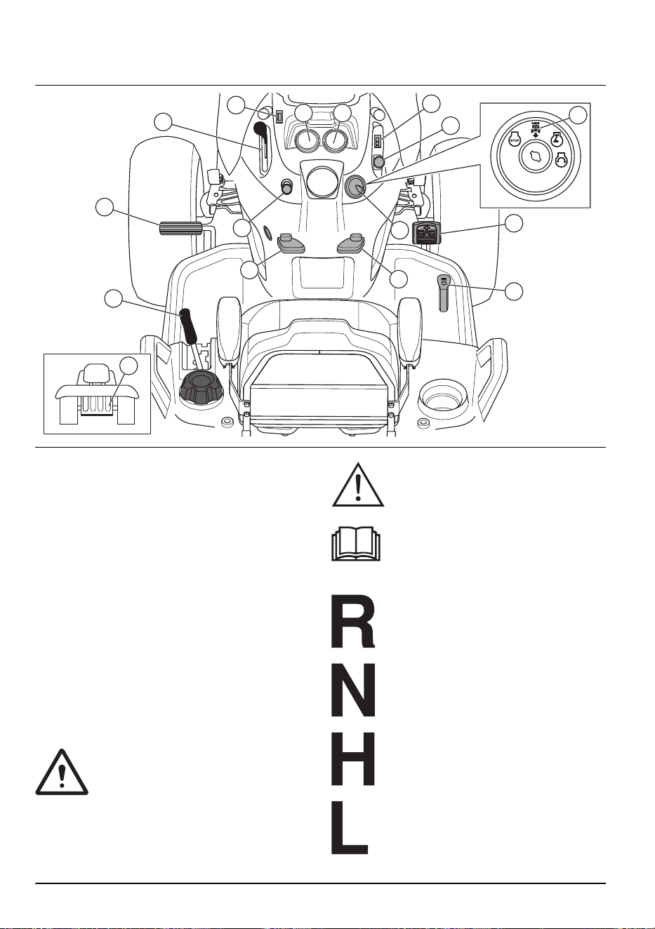
Descripción general del producto
16
15
14
1
2
13
12
11
7
6
5
8
9
43
10
1. Control del acelerador
2. Interruptor de luz
3. Medidor de horas
4. Amperímetro
5. Interruptor de bloqueo del diferencial
6. Botón de PTO
7. Interruptor de encendido
8. Sistema de funcionamiento en reversa (ROS) en la
posición ON
9. Pedal para avanzar
10. Pedal de reversa
11. Palanca de control crucero
12. Palanca del freno de estacionamiento
13. Estrangulador
14. Pedal de freno
15. Palanca de elevación de accesorio
16. Palanca de rueda libre
Símbolos en el producto
Advertencia: Tenga cuidado y utilice el
producto correctamente. Este producto
puede causar daños graves o fatales al
operador o a otras personas.
PRECAUCIÓN: El uso incorrecto puede
causar daños al producto o a la propiedad
personal.
Lea atentamente el manual de
instrucciones y asegúrese de que
entiende las instrucciones antes de usar
este producto.
Reversa.
Neutro.
Alta.
Baja.
42 2231 - 003 - 22.09.2023
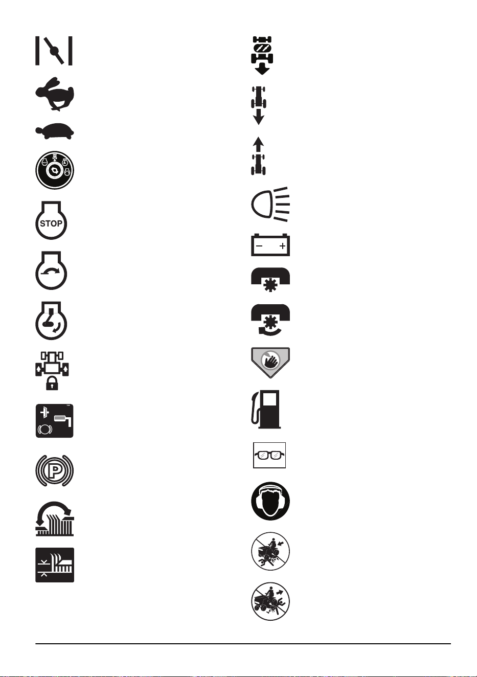
Estrangulador.
Rápido.
Lento.
Interruptor de encendido.
Motor apagado.
Puesta en marcha del motor.
Motor en marcha.
Bloqueo de diferencial.
Pedal de embrague y de freno.
Freno de estacionamiento.
Altura de corte.
Elevación del equipo de corte.
Sistema de funcionamiento en reversa
(ROS).
Reversa.
Hacia delante.
Luces encendidas.
Batería.
Las cuchillas están desacopladas.
Las cuchillas están acopladas.
Peligroso, mantenga las manos y los pies
alejados esta área.
Combustible.
Utilice gafas protectoras.
Use protección auricular aprobada.
Mantenga la zona despejada cuando
conduzca hacia delante.
No haga funcionar el producto mientras
haya animales o personas cerca,
especialmente niños.
2231 - 003 - 22.09.2023 43

Riesgo de pendiente. No opere el
producto en subida en una pendiente
mayor que 15°.
Riesgo de pendiente. No opere
horizontalmente en una pendiente.
Riesgo de pendiente. No opere el
producto en bajada en una pendiente
mayor que 15°.
El símbolo de superficies calientes indica
que hay un riesgo que, si no se
evita, podría provocar la muerte, lesiones
graves o daños.
El símbolo de fuego indica que hay un
riesgo que, si no se evita, podría provocar
la muerte, lesiones graves o daños.
Control crucero.
Rueda libre (solo modelos automáticos).
Etiqueta en el producto
PELIGRO: mantenga las manos y los pies lejos.
Medidor de horas
El medidor de horas muestra por cuántas horas ha
funcionado el motor. Consulte
Descripción general del
producto en la página 42
para conocer la posición del
medidor de horas.
Para restablecer manualmente el medidor de horas, gire
la llave de encendido a la posición de encendido y,
luego, a la posición “STOP” cinco veces.
Tenga en cuenta: El medidor de horas solo se
detiene cuando la llave de encendido está en la posición
“STOP”. Asegúrese de que la llave de encendido
permanezca en la posición “STOP” cuando el motor se
haya detenido.
Daños en el producto
No somos responsables de los daños a nuestro
producto en los siguientes casos:
• el producto se repara incorrectamente
• el producto se repara con piezas que no son del
fabricante o que este no autoriza
• el producto tiene un accesorio que no es del
fabricante o que este no autoriza
• el producto no se repara en un centro de servicio
autorizado o por una autoridad aprobada.
Seguridad
Definiciones de seguridad
Las advertencias, precauciones y notas se utilizan
para señalar las piezas particularmente importantes del
manual.
ADVERTENCIA: Se utilizan para
señalar el riesgo de lesiones graves o
mortales para el operador o para aquellos
que se encuentren cerca si no se siguen las
instrucciones del manual.
AVISO: Se utilizan para señalar el riesgo
de dañar la máquina, otros materiales o
el área adyacente si no se siguen las
instrucciones del manual.
44 2231 - 003 - 22.09.2023
Tenga en cuenta: Se utilizan para entregar más
información necesaria en situaciones particulares.
Prácticas de uso seguro para
cortacésped
ADVERTENCIA: Este producto
puede amputar manos y pies, y arrojar
objetos. El incumplimiento de las siguientes
instrucciones de seguridad puede ocasionar
daños graves o la muerte.
ADVERTENCIA: Siempre
desconecte el cable de la bujía y colóquelo
en un lugar en el que no entre en
contacto con la bujía para evitar el arranque
accidental durante la configuración, el
transporte, o cuando esté haciendo ajustes
o reparaciones.
ADVERTENCIA: No baje pendientes
en punto muerto, ya que puede perder el
control del tractor.
ADVERTENCIA: Remolque
únicamente con accesorios recomendados
por las especificaciones del fabricante del
tractor y cumpla con las especificaciones
de este. Use el sentido común al remolcar.
Cuando esté en una pendiente, utilice la
máquina únicamente a la velocidad más
baja posible. Es peligroso transportar mucho
peso cuando opere la máquina en una
pendiente. Debido a que es posible que los
neumáticos pierdan tracción con el suelo, lo
que puede provocar que pierda el control
del tractor.
ADVERTENCIA: Los gases de
escape del motor, algunos de sus
componentes y algunos componentes del
vehículo contienen o emiten productos
químicos que según el estado de California
provocan cáncer y malformaciones
congénitas u otros daños reproductivos.
ADVERTENCIA: Los postes, las
terminales y los accesorios relacionados de
la batería contienen plomo y compuestos
de plomo, productos químicos de los que
se sabe en el Estado de California que
causan cáncer y defectos de nacimiento
u otros daños reproductivos. Lávese las
manos después de su uso.
I. NIÑOS
ADVERTENCIA: LOS NIÑOS
PUEDEN RESULTAR LESIONADOS POR
ESTE EQUIPO. La Academia Americana de
Pediatría recomienda que los niños tengan
un mínimo de 12 años antes de operar un
cortacésped de manejo a pie y un mínimo
de 16 años antes de operar un cortacésped
montado.
ADVERTENCIA: ESTE EQUIPO ES
PELIGROSO PARA LOS NIÑOS, PUEDE
CAUSAR LESIONES GRAVES O LA
MUERTE. Lea atentamente las siguientes
instrucciones de seguridad y cumpla lo que
se indica.
Pueden ocurrir accidentes trágicos si el operador no
está alerta de la presencia de niños. A los niños suelen
atraerles las máquinas y el corte del césped. Nunca dé
por un hecho que los niños permanecerán donde usted
los vio por última vez.
• Mantenga a los niños alejados de la zona de corte y
bajo la supervisión de un adulto responsable aparte
del operador.
• Manténgase alerta y apague la máquina si los niños
entran al área.
• Antes y mientras vaya en reversa, mire hacia atrás y
hacia abajo por si hay niños presentes.
• Nunca lleve niños arriba de la máquina, incluso
cuando las cuchillas estén desactivadas. Pueden
caerse y lesionarse gravemente o interferir en el
funcionamiento seguro de la máquina. Los niños
a quienes se les da una vuelta en la máquina
pueden aparecer de repente en el área de corte
para otra vuelta y ser atropellados o golpeados con
la máquina.
• Nunca permita que los niños operen la máquina.
• Tenga extremo cuidado cuando se acerca a curvas
sin visibilidad, arbustos, árboles u otros objetos que
puedan bloquear su visión e impedir que vea a un
niño.
II. OPERACIÓN GENERAL
• Lea, entienda y siga todas las instrucciones sobre la
máquina en el manual antes de comenzar.
• No coloque las manos ni los pies cerca de
las partes giratorias ni debajo de la máquina.
Manténgase alejado de la abertura de descarga en
todo momento.
• Solo permita que los adultos responsables, que
estén familiarizados con las instrucciones, operen la
máquina.
• Quite de la zona objetos como rocas, juguetes,
cables, etc. que podrían engancharse en la cuchilla
y ser arrojados.
2231 - 003 - 22.09.2023
45
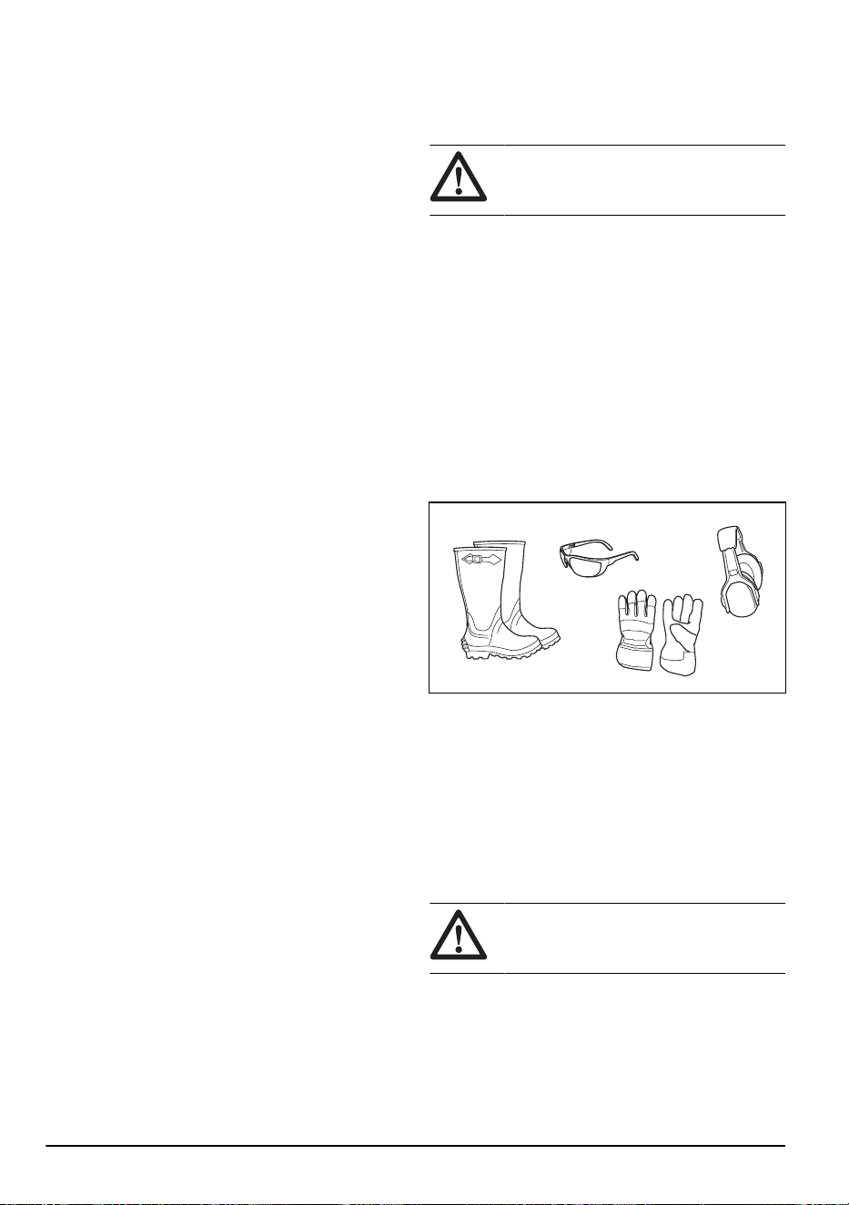
• Asegúrese de que el área esté libre de personas
antes de comenzar la operación. Detenga la
máquina si alguien entra en el área.
• Nunca transporte pasajeros
• No corte el césped en reversa a menos que sea
absolutamente necesario. Siempre mire hacia abajo
y hacia atrás antes y cuando vaya en reversa.
• Nunca dirija el material que se descarga hacia
nadie. Evite descargar el material contra una pared
u otra obstrucción. El material puede rebotar hacia
el operador. Detenga las cuchillas cuando atraviese
superficies de grava.
• No maneje la máquina si no tiene la trampa
para césped completa, la canaleta de descarga u
otros dispositivos de seguridad en su lugar y en
funcionamiento.
• Desacelere antes de dar la vuelta.
• Nunca deje la máquina en funcionamiento sin
vigilar. Siempre apague las hojas, coloque la hoja
de estacionamiento y detenga el motor antes de
bajarse.
• Desenganche las hojas cuando no esté cortando
césped. Apague el motor y espere que todas
las piezas se detengan completamente antes de
limpiar la máquina, quitar el recogedor de césped
o destapar el conducto de expulsión.
• Opere la máquina únicamente durante el día o con
buena luz artificial.
• No opere la máquina mientras esté bajo la influencia
de alcohol o drogas.
• Esté pendiente del tráfico cuando opere la máquina
cerca de caminos o al cruzarlos.
• Tenga extremo cuidado cuando cargue o descargue
la máquina de un remolque o camión.
• Use siempre protección ocular cuando opere la
máquina.
• Utilice protectores auriculares para evitar daños en
los oídos.
• Los datos indican que los operadores de 60 o
más años de edad se ven involucrados en un
alto porcentaje de lesiones relacionadas con los
cortacéspedes. Estos operadores deben evaluar su
capacidad para utilizar el cortacésped de forma
suficientemente segura como para protegerse a sí
mismos y a los demás de lesiones graves.
• Siga las recomendaciones del fabricante para los
pesos de las ruedas o los contrapesos.
• Mantenga la máquina sin césped, hojas o
acumulación de otros restos que puedan tocar las
partes calientes del escape o del motor e inflamarse.
No permita que la plataforma de la cortadora de
césped levante hojas u otra basura que pueda
causar acumulaciones. Limpie cualquier derrame de
aceite o combustible antes de operar o almacenar la
máquina. Permita que la máquina se enfríe antes de
almacenarla.
Instrucciones de seguridad para el
funcionamiento
Equipo de protección personal
ADVERTENCIA: Lea atentamente
las instrucciones de advertencia siguientes
antes de usar el producto.
• Utilice siempre el equipo de protección personal
aprobado cuando use el producto. El equipo de
protección personal no puede impedir el riesgo de
lesiones, pero disminuirá el grado de lesión si ocurre
un accidente. Permita que su distribuidor lo ayude a
seleccionar el equipo adecuado.
• Use siempre protectores auriculares aprobados. La
exposición prolongada al ruido puede causar la
pérdida permanente de la audición.
• Siempre use gafas de seguridad o protección ocular
cuando opere el producto o realice tareas de
mantenimiento o reparación.
• Use siempre zapatos o botas de protección. Se
recomienda usar punteras de acero. No utilice el
producto descalzo.
• Utilice guantes cuando sea necesario, por ejemplo,
cuando conecte, examine o limpie el equipo de
corte.
• No use ropa floja, joyas u otros artículos que puedan
quedar atrapados en las piezas móviles.
• No utilice pantalones cortos cuando utilice el
producto.
• Mantenga un equipo de primeros auxilios y un
extintor de incendios a mano.
Dispositivos de seguridad en el producto
ADVERTENCIA:
Lea atentamente
las instrucciones de advertencia siguientes
antes de usar el producto.
• No utilice un producto con dispositivos de seguridad
dañados o que no funcionen correctamente.
Revise los dispositivos de seguridad de forma
regular. Si los dispositivos de seguridad están
dañados, comuníquese con el agente de servicio de
Husqvarna.
46
2231 - 003 - 22.09.2023
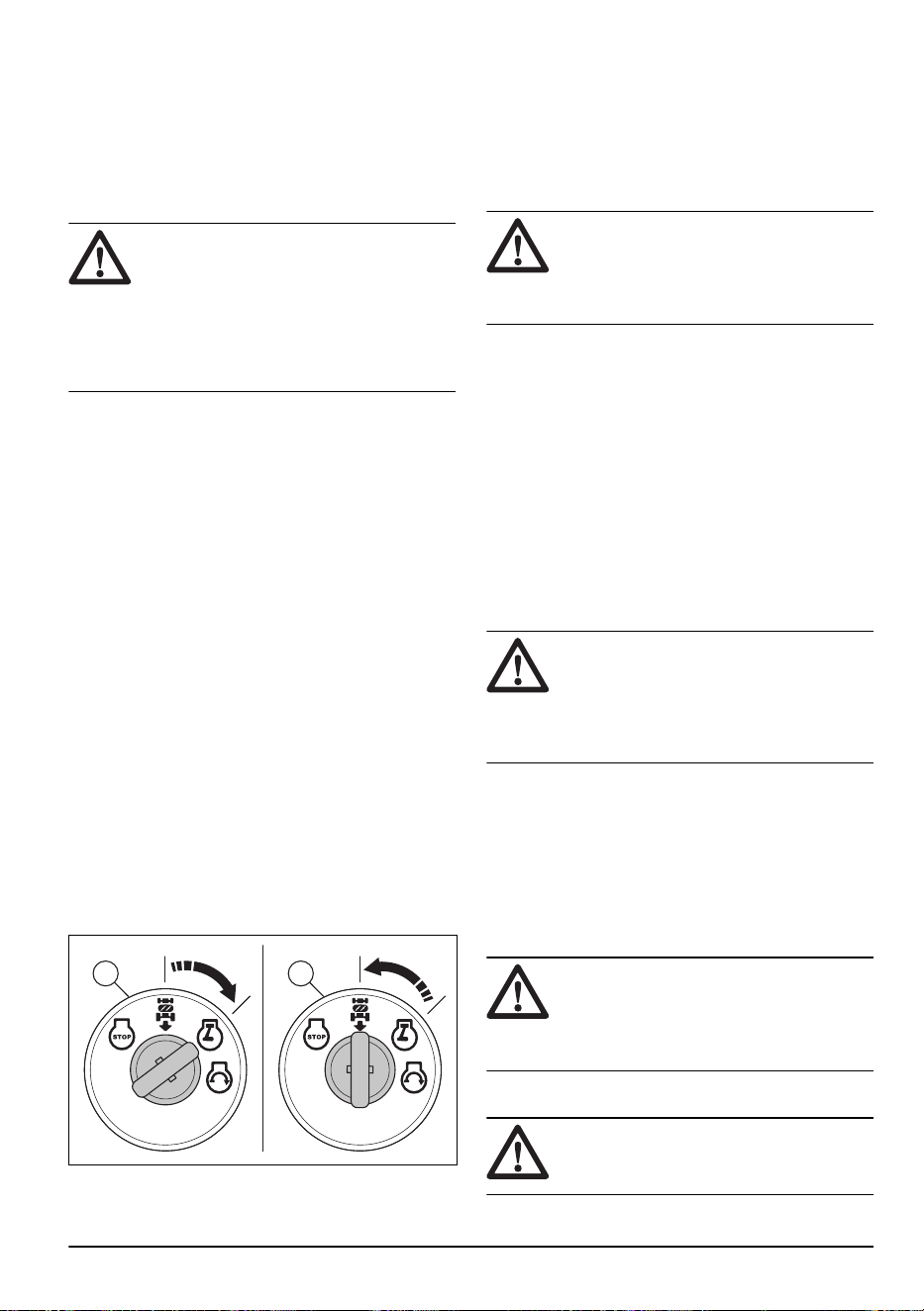
• No realice ninguna modificación en los dispositivos
de seguridad. No utilice el producto si las placas
de protección, las cubiertas de protección, los
interruptores de seguridad u otros dispositivos
protectores no están acoplados o están dañados.
Para verificar el control de presencia del operador
(OPC)
ADVERTENCIA: No opere el
producto con un control de presencia
del operador (OPC, del inglés Operator
Presence Control) que no funcione
correctamente. Si el OPC no funciona
correctamente, repárelo de inmediato.
Comuníquese con un taller de servicio
autorizado.
• Asegúrese de que el motor no pueda arrancar,
a menos que el pedal de freno se presione
completamente hacia abajo y el equipo de corte esté
desacoplado.
• Asegúrese de que el motor se detenga cuando
el operador se aleje del asiento y el freno de
estacionamiento esté desacoplado.
• Asegúrese de que el motor se detenga cuando el
operador se aleje del asiento y el equipo de corte
esté accionado.
• Asegúrese de que el control del embrague del
equipo de corte no pueda funcionar cuando el
operador esté lejos del asiento.
Para verificar el sistema de funcionamiento en reversa
(ROS)
Si el sistema ROS no funciona correctamente, repare el
producto de inmediato. Comuníquese con un taller de
servicio autorizado.
1. Encienda el producto. Consulte
Para poner en
marcha el producto en la página 53
.
2. Acople el equipo de corte. Consulte
Para acoplar y
desacoplar el equipo de corte en la página 57
.
3. Asegúrese de que el motor se detenga cuando
intente retroceder con la llave de encendido en la
posición on (A).
BA
4. Ponga en marcha el producto y vuelva a acoplar el
equipo de corte.
5. Coloque el interruptor de encendido en la posición
de encendido de ROS (B).
6. Asegúrese de que el motor no se detenga cuando
vaya en reversa con la llave de encendido en la
posición de encendido de ROS.
Para comprobar el freno
ADVERTENCIA: El mantenimiento
de los frenos es necesario si el producto se
utiliza más de 5pies (1,5m), y se detiene a
la máxima velocidad en la marcha más alta
sobre una superficie nivelada y seca.
1. Estacione el producto en una superficie nivelada,
seca, de cemento o pavimento. Presione el pedal
de freno completamente y acople el freno de
estacionamiento.
2. Coloque el control de la rueda libre en la posición
de "transmisión desacoplada" para desacoplar la
transmisión.
3. Las ruedas traseras deben bloquearse y patinar
cuando se intente empujar manualmente el producto
hacia delante. Si las ruedas traseras giran, es
necesario el mantenimiento del freno.
4. Consulte a un centro de servicio autorizado.
Freno de estacionamiento
ADVERTENCIA: Si el freno de
estacionamiento no funciona, el producto
puede empezar a moverse y causar
lesiones o daños. Asegúrese de revisar
y ajustar el freno de estacionamiento con
regularidad.
Consulte
Para comprobar el freno en la página 47
.
Silenciador
El silenciador mantiene los niveles de ruido al mínimo y
envía los gases de escape lejos del operador.
No utilice el producto si el silenciador no está instalado
o está dañado. Un silenciador dañado aumenta el nivel
de ruido y el riesgo de incendio.
ADVERTENCIA:
El silenciador se
calienta mucho durante y después del uso
y cuando el motor funciona en régimen de
ralentí. Tenga cuidado cerca de materiales o
vapores inflamables para prevenir incendios.
Para cortar césped en pendientes
ADVERTENCIA:
Lea atentamente
las instrucciones de advertencia siguientes
antes de usar el producto.
2231 - 003 - 22.09.2023 47
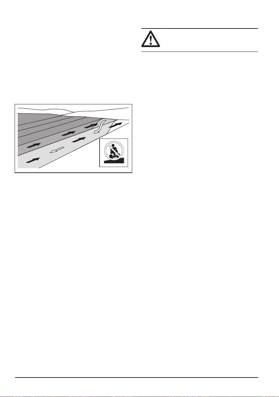
• Cortar el césped en pendientes aumenta el riesgo
de que no pueda controlar el producto y de que se
vuelque. Esto puede provocar lesiones o la muerte.
Es necesario tener cuidado al cortar el césped en
cualquier pendiente. Si no puede retroceder para
subir una pendiente o si no se siente seguro, no la
corte.
• Quite las piedras, las ramas y otros obstáculos.
• Corte hacia arriba y hacia abajo por la pendiente, no
de lado a lado.
• No descienda una pendiente con el equipo de corte
levantado.
• No utilice el producto en suelos con pendientes de
más de 15°.
>15°
• No efectúe arranques ni paradas en una pendiente.
• Muévase suave y lentamente en pendientes.
• No haga cambios repentinos de velocidad o
dirección.
• No gire más de lo necesario. Gire lenta y
gradualmente cuando se mueva hacia abajo en una
pendiente. Muévase a baja velocidad. Gire la rueda
con cuidado.
• Ponga atención a la presencia de surcos, agujeros y
baches, y no pase transversalmente por ellos. Existe
un mayor riesgo de que el producto se vuelque en
suelo que no es plano. El césped alto puede ocultar
obstáculos.
• No corte el césped cerca de bordes, zanjas u orillas.
Mantenga al menos el ancho del producto alejado
de estos peligros. El producto puede volcarse
repentinamente si una rueda se desplaza por el
borde de una pendiente pronunciada o una zanja,
o si un borde cede.
• No corte el césped húmedo. Es resbaladizo y los
neumáticos pueden perder adherencia, de modo
que el producto podría patinar.
• No ponga el pie en el suelo para tratar de darle más
estabilidad al producto.
• Si un accesorio u otro objeto instalado pueden
restarle estabilidad al producto, muévase con mucho
cuidado.
Seguridad de combustible
ADVERTENCIA: Lea atentamente
las instrucciones de advertencia siguientes
antes de usar el producto.
• La gasolina es inflamable y sus gases son
explosivos. Tenga cuidado con el combustible para
evitar lesiones, incendios y explosiones.
• No inhale los gases del combustible. Los gases del
combustible son tóxicos y pueden provocar lesiones.
Asegúrese de que el flujo de aire sea suficiente.
• No retire la tapa del depósito de combustible ni llene
el depósito con el motor encendido.
• Asegúrese de que el motor se enfríe antes de llenar
el depósito de combustible.
• No llene el depósito de combustible en interiores.
Un flujo de aire insuficiente puede causar lesiones
graves o fatales por asfixia o intoxicación por
monóxido de carbono.
• No fume cerca del combustible o del motor.
• No coloque objetos calientes cerca del combustible
o del motor.
• No llene el depósito de combustible cerca de
chispas o llamas.
• Antes de llenar el depósito de combustible, abra
lentamente la tapa del depósito de combustible y
libere la presión con cuidado.
• Si el combustible entra en contacto con la piel,
puede provocar lesiones. Si le cae combustible en
la piel, quítelo con jabón y agua.
• Si derrama combustible en su ropa, cámbiese la
ropa inmediatamente.
• No llene el depósito de combustible completamente.
El calor provoca que el combustible se expanda.
Deje espacio en la parte superior del depósito de
combustible.
• Apriete bien la tapa del depósito de combustible. Si
no aprieta la tapa del depósito de combustible, se
genera un riesgo de incendio.
• Antes de poner en marcha el producto, colóquelo a
una distancia mínima de 3m/10pies desde el lugar
donde llenó el depósito de combustible.
• No arranque el producto si hay combustible o aceite
de motor en el producto. Elimine el combustible y el
aceite del motor no deseados y deje que el producto
se seque antes de arrancar el motor.
• Examine frecuentemente el motor en busca de
fugas. Si hay fugas en el sistema de combustible,
no arranque el motor hasta que las repare.
• No busque fugas en el motor con los dedos.
• Almacene el combustible solo en recipientes
aprobados.
• Cuando el producto y el combustible estén
almacenados, asegúrese de que el combustible y
los gases del combustible no puedan causar daños.
• Vacíe el combustible en un recipiente aprobado en
exteriores y lejos de chispas y llamas.
48
2231 - 003 - 22.09.2023
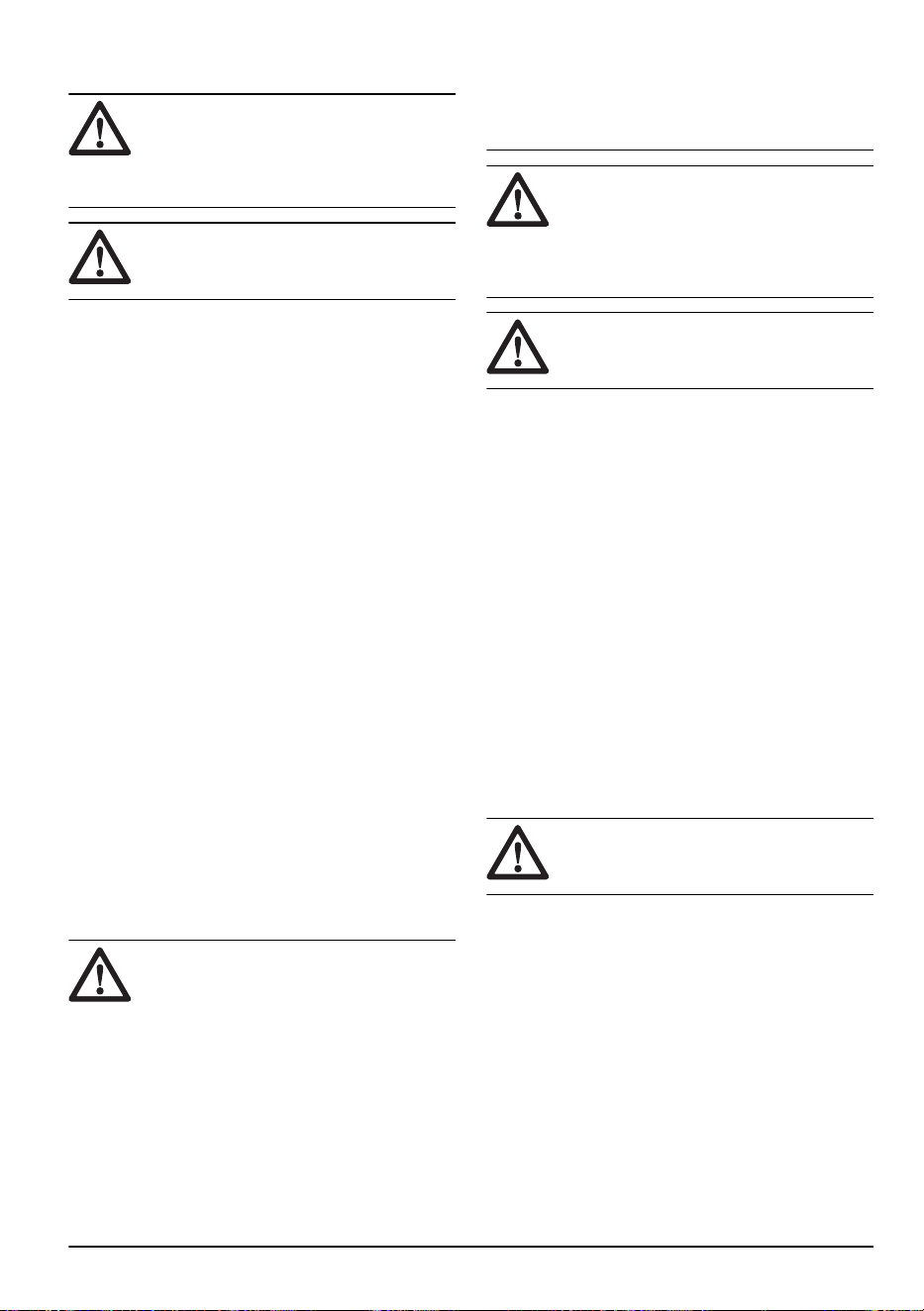
Seguridad de la batería
ADVERTENCIA: Una batería dañada
puede provocar una explosión y causar
lesiones. Si la batería tiene una deformación
o está dañada, hable con un taller de
servicio Husqvarna autorizado.
ADVERTENCIA: Lea atentamente
las instrucciones de advertencia siguientes
antes de usar el producto.
• Utilice gafas protectoras cuando esté cerca de las
baterías.
• No use relojes, joyas u otros objetos metálicos cerca
de la batería.
• Almacene la batería fuera del alcance de los niños.
• Cargue la batería en un espacio con buena
ventilación.
• Mantenga los materiales inflamables a una distancia
mínima de 1m cuando cargue la batería.
• Deseche las baterías que ha reemplazado. Consulte
Eliminación en la página 82
.
• La batería puede generar gases explosivos. No
fume cerca de la batería. Mantenga la batería lejos
de llamas abiertas y chispas.
Seguridad del transporte
• Utilice un vehículo de transporte aprobado para el
transporte del producto.
• El producto es pesado y puede causar lesiones por
aplastamiento. Tenga cuidado cuando lo cargue o
descargue de un vehículo o remolque.
• Las normativas nacionales o locales de mercados
pueden establecer un límite para el transporte del
producto.
• El operador de vehículo de transporte es
responsable de fijar el producto de forma segura
durante el transporte. Consulte
Transporte en la
página 81
.
Instrucciones de seguridad para el
mantenimiento
ADVERTENCIA:
El producto es
pesado y puede causar lesiones o daños a
la propiedad o el área adyacente. No realice
mantenimiento del motor o del equipo
de corte sin cumplir con las siguientes
condiciones:
• El sistema está apagado.
• El producto está estacionado en una
superficie nivelada.
• El freno de estacionamiento está
aplicado.
• La llave de encendido se ha retirado.
• El equipo de corte está desacoplado.
• Quitó los cables de encendido de las
bujías.
ADVERTENCIA: Los gases de
escape del motor contienen monóxido de
carbono, un gas inodoro, tóxico y muy
peligroso. No haga funcionar el producto en
espacios cerrados o sin suficiente flujo de
aire.
ADVERTENCIA: Lea atentamente
las instrucciones de advertencia antes de
realizar mantenimiento al producto.
• Para lograr mayores niveles de rendimiento y
seguridad, realice el mantenimiento del producto
con regularidad como se indica en el programa de
mantenimiento. Consulte la sección
Programa de
mantenimiento en la página 60
.
• Las sacudidas eléctricas pueden causar lesiones.
No toque los cables cuando el motor esté
encendido. No haga una prueba de funcionamiento
del sistema de encendido con los dedos.
• No arranque el motor si las cubiertas protectoras
están desmontadas. Existe un gran riesgo de que
las piezas móviles o calientes causen lesiones.
• Deje que el producto se enfríe antes de realizar
tareas de mantenimiento cerca del motor.
• Las cuchillas son filosas y pueden causar cortes.
Envuelva las cuchillas con protección o utilice
guantes protectores cuando trabaje en las cuchillas.
• Siempre ponga el equipo de corte en la posición
de servicio para limpiarlo. No estacione el producto
cerca del borde de una zanja o pendiente para
acceder al equipo de corte.
AVISO:
Lea atentamente las
instrucciones siguientes antes de usar el
producto.
• No gire el motor si el cable de encendido o la bujía
están desconectados.
• Asegúrese de que todas las tuercas y pernos estén
correctamente apretados y de que el equipo está en
buen estado.
• No cambie el ajuste de los reguladores. Si
el régimen del motor es demasiado alto, los
componentes del producto pueden dañarse.
• El producto se ha aprobado solo con el equipo
proporcionado originalmente o recomendado por el
fabricante.
2231 - 003 - 22.09.2023
49

Montaje
Introducción
ADVERTENCIA: Asegúrese de leer
y comprender el capítulo de seguridad antes
de montar el producto.
Para extraer el producto de la caja de
cartón
1. Retire las piezas sueltas que se incluyen con el
producto.
2. Retire los paneles del extremo.
3. Retire los paneles laterales y colóquelos en una
superficie plana.
4. Retire todos los materiales de embalaje.
5. Retire el producto de la caja y asegúrese de que no
queden piezas sueltas en la caja.
Herramientas de montaje
Tenga en cuenta: El proceso de armado será
más simple si cuenta con un conjunto de llaves de cubo.
• Llave de 1/2” (13mm)
• Calibrador de la presión de los neumáticos
• Cuchilla de utilidad
• Alicate
Piezas sueltas que necesitan montaje
El producto no está completamente montado. Las
siguientes piezas están sueltas en el momento de
comprar el producto.
Llave, 2 piezas
Hoja de pendiente, 1 pieza
Perno hexagonal, 2 piezas
Tuercas, 2 piezas
Adaptador de boquilla, 1 pieza
Tubo de vaciado de aceite, 1 pieza
Perilla de ajuste del asiento, 2piezas
Perno de ajuste del asiento, 2piezas
Tope del asiento, 2piezas
Perno para el tope del asiento, 2piezas
Asiento, 1 piezas
Para instalar el asiento
1. Pliegue la base del asiento hacia delante.
50
2231 - 003 - 22.09.2023

2. Instale los 2 parachoques (A) en la base del asiento
(B) con los 2pernos (C).
A
C
B
3. Sujete el asiento (D) en la posición correcta e instale
1 de las 2 perillas de ajuste del asiento (E) en 1 de
los orificios de ajuste (F) de la base del asiento.
E
G
D
F
H
4. Instale la otra perilla de ajuste del asiento (G).
5. Instale los 2pernos (H) en las ranuras de la base del
asiento.
6. Ajuste el asiento antes de usar el producto. Consulte
Para ajustar el asiento en la página 51
.
Para ajustar el asiento
1. Pliegue el asiento hacia delante y retire la perilla de
ajuste del asiento (A).
A
B
2. Afloje la perilla de ajuste del asiento (B).
3. Mueva el asiento hasta que esté en una posición
donde pueda presionar los pedales de freno y
embrague hacia abajo.
4. Alinee uno de los orificios de la base del asiento con
el orificio en el asiento e instale la perilla de ajuste
del asiento (A).
5. Apriete las 2perillas de ajuste del asiento
completamente.
Para ajustar la altura del asiento
La altura del asiento se puede ajustar en 2posiciones:
posición más alta y posición más baja. El asiento está
instalado en la posición más alta de fábrica.
1. Pliegue el asiento hacia delante.
2231 - 003 - 22.09.2023
51
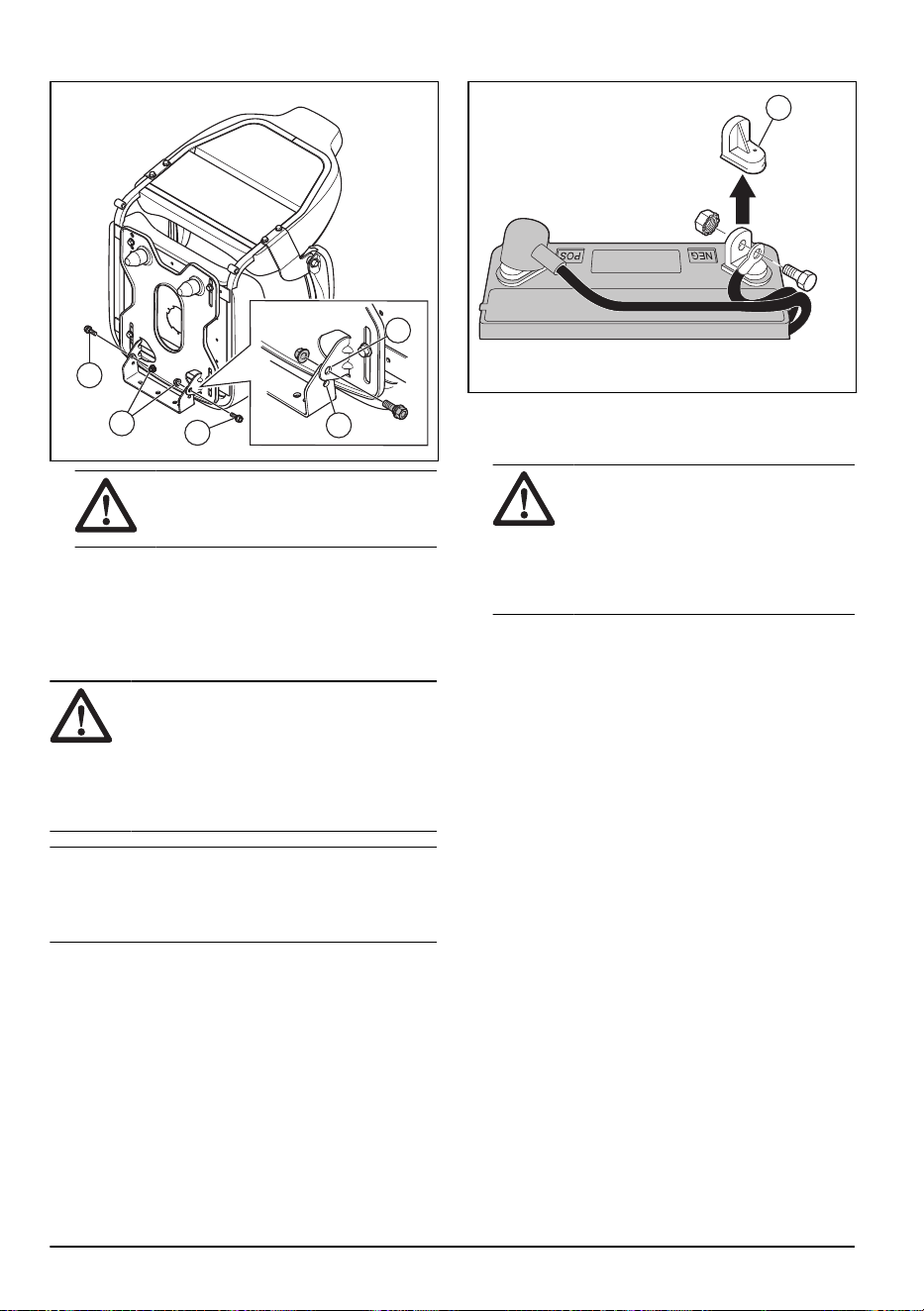
2. Quite los 2pernos (A) y las 2tuercas (B).
C
D
A
A
B
ADVERTENCIA: El asiento y la
base del asiento se aflojan cuando se
quitan los pernos y las tuercas.
3. Alinee los orificios de la base del asiento con los
orificios de la posición más alta (C) o más baja (D).
Instale los pernos y las tuercas.
4. Apriete todos los pernos por completo.
Para conectar la batería
ADVERTENCIA:
Riesgo de sacudida
eléctrica y quemaduras. No utilice pulseras
metálicas ni otros accesorios metálicos. Los
elementos metálicos que entran en contacto
con los terminales de la batería pueden
causar quemaduras, sacudidas eléctricas y
cortocircuito de la batería.
Tenga en cuenta: Si la fecha actual es posterior
al año y al mes que se escribió en la etiqueta de la
batería, cárguela. Cargue la batería durante un mínimo
de una hora entre 6 y 10amperios.
1. Busque la ubicación de la batería debajo del asiento
o de la cubierta del motor.
2. Levante la base del asiento o la cubierta del motor
hasta la posición elevada.
3. Retire los dos tapones del terminal (A) y deséchelos.
A
4. Conecte el cable rojo de la batería al terminal
positivo (+) y apriete el perno y la tuerca como se
indica. Mueva la tapa del terminal en el terminal.
ADVERTENCIA: Riesgo de
chispas. El cable rojo de la batería se
debe conectar al terminal positivo antes
de conectar el cable negro de la batería
al terminal negativo. Esto es para evitar
chispas y conexiones accidentales a
tierra.
5. Conecte el cable negro al terminal negativo (-) y
apriete firmemente el perno y la tuerca.
6. Aplique vaselina en los cables de la batería para
evitar la corrosión.
7. Baje la base del asiento o la cubierta del motor.
Para retirar el producto de la plancha
1. Levante el equipo de corte a su posición más alta.
Utilice la palanca de elevación.
2. Presione el pedal del embrague/freno para liberar el
freno de estacionamiento.
3. Ponga el control de la rueda libre en la
posición Transmission disengaged (Transmisión
desacoplada), consulte
Transporte, almacenamiento
y eliminación de residuos en la página 81
.
4. Empuje el producto hacia delante de la plancha.
5. Quite la correa que sujeta la protección del deflector
contra el producto.
Para comprobar el montaje
• Asegúrese de completar todas las instrucciones de
montaje.
• Asegúrese de que no haya piezas restantes en el
embalaje.
• Asegúrese de que la batería esté preparada y
correctamente cargada.
52
2231 - 003 - 22.09.2023
• Asegúrese de que los pernos del asiento estén
apretados y de que el asiento esté ajustado
correctamente.
• Asegúrese de que los neumáticos estén
correctamente inflados.
• Para obtener mejores resultados de corte,
asegúrese de que el equipo de corte esté
equilibrado de lado a lado y de la parte delantera
a la parte trasera. Asegúrese de que los neumáticos
estén correctamente inflados para que el equipo de
corte esté equilibrado.
• Examine el equipo de corte y las correas de
transmisión. Asegúrese de que las correas estén
instaladas correctamente alrededor de las poleas
y la parte interior de todos los sujetadores de la
correa.
• Examine los cables eléctricos. Asegúrese de que
todos los cables y conexiones sean seguros.
• Asegúrese de que el control de la rueda libre esté
en la posición Transmission engaged (Transmisión
acoplada). Consulte
Transporte en la página 81
.
• Asegúrese de que el aceite del motor esté en el
nivel correcto.
• Asegúrese de que el depósito esté lleno con el tipo
correcto de combustible.
• Asegúrese de conocer la ubicación y la función de
todos los controles.
• Asegúrese de que el sistema de freno esté en
condiciones seguras para funcionar.
• Asegúrese de que el control de presencia del
operador (OPC) y el sistema de funcionamiento
en reversa (ROS, del inglés “Reverse Operation
System”) funcionen correctamente. Consulte
Para
verificar el control de presencia del operador (OPC)
en la página 47
y
Para verificar el sistema de
funcionamiento en reversa (ROS) en la página 47
.
• Retire el aire de la transmisión antes del primer
uso. Consulte
Para extraer el producto desde la
transmisión en la página 74
.
Funcionamiento
Introducción
ADVERTENCIA: Asegúrese de leer
y comprender el capítulo de seguridad antes
de utilizar el producto.
Para agregar combustible
ADVERTENCIA: La gasolina es muy
inflamable. Tenga cuidado y reabastezca
combustible al aire libre. Consulte
Seguridad
de combustible en la página 48
.
AVISO: Utilice siempre el tipo de
combustible correcto. El tipo de combustible
incorrecto puede causar daños en el
producto.
• Utilice el tipo correcto de gasolina. Consulte
Datos técnicos en la página 82
. Para obtener
más información sobre el combustible, consulte el
manual del motor proporcionado por el fabricante.
• Realice una comprobación del nivel de combustible
antes de cada uso y agregue combustible si es
necesario.
• No llene completamente el depósito de combustible.
Mantenga un espacio mínimo de 1pulgada.
Para poner en marcha el producto
Antes de arrancar el producto
ADVERTENCIA: Antes de operar el
producto, lea cuidadosamente y comprenda
las instrucciones de seguridad y las
instrucciones de funcionamiento.
1. Revise el nivel de aceite del motor. Consulte
Para
revisar el nivel de aceite del motor en la página 72
.
2. Llene el depósito con combustible. Consulte
Para
agregar combustible en la página 53
.
3. Desconecte el modo de rueda libre. Consulte
Para
poner el producto en modo de rueda libre en la
página 58
.
4. Siéntese en la posición de operación.
5. Acople el freno de estacionamiento. Consulte
Para
acoplar y desacoplar el freno de estacionamiento en
la página 56
.
6. Asegúrese de que el equipo de corte esté
desacoplado. Consulte
Para acoplar y desacoplar el
equipo de corte en la página 57
.
Para arrancar un motor caliente
1. Siéntese en el asiento.
2. Asegúrese de que el equipo de corte esté
desacoplado. Consulte
Para acoplar y desacoplar el
equipo de corte en la página 57
.
3. Coloque el equipo de corte en la posición de
transporte. Consulte
Para colocar el equipo de corte
en la posición de transporte o posición de corte en la
página 55
.
2231 - 003 - 22.09.2023
53

4. Mueva el acelerador a la posición rápida.
5. Extraiga el estrangulador.
Tenga en cuenta: Para arrancar el motor en
caliente, es posible que no sea necesario utilizar el
estrangulador.
6. Pise el pedal de freno completamente y manténgalo
presionado.
7. Coloque la llave de encendido en la posición de
encendido.
8. Gire la llave de encendido a la posición "START"
y suelte la llave de encendido cuando el motor
arranque.
AVISO: No encienda el motor de
arranque de forma continua durante más
de 15segundos por minuto.
9. Cuando el motor haya arrancado, presione
lentamente el estrangulador hasta que el motor
funcione sin problemas. Cuando el motor funciona
correctamente, el equipo conectado, la transmisión
de avance y la transmisión de reversa se pueden
operar.
Tenga en cuenta: Si el motor funciona
de forma irregular, retire el estrangulador durante
unos segundos y, luego, siga presionando el
estrangulador lentamente.
Tenga en cuenta: Si el motor no acepta
la carga, reinicie el motor y deje que se caliente
durante un minuto. Siga las instrucciones anteriores.
Para arrancar un motor frío
1. Siéntese en el asiento.
2. Asegúrese de que el equipo de corte esté
desacoplado. Consulte
Para acoplar y desacoplar el
equipo de corte en la página 57
.
3. Coloque el equipo de corte en la posición de
transporte. Consulte
Para colocar el equipo de corte
en la posición de transporte o posición de corte en la
página 55
.
4. Mueva el acelerador hasta la posición de
aceleración intermedia.
5. Extraiga el estrangulador.
6. Pise el pedal de freno completamente y manténgalo
presionado.
7. Coloque la llave de encendido en la posición de
encendido.
8. Gire la llave de encendido a la posición "START"
y suelte la llave de encendido cuando el motor
arranque.
AVISO: No encienda el motor de
arranque de forma continua durante más
de 15segundos por minuto.
Tenga en cuenta: Si el motor no
arranca después de algunos intentos, presione el
estrangulador y espere unos minutos antes de
volver a intentarlo.
9. Cuando el motor arranque, mueva el acelerador
a la posición rápida para calentar el motor. Si la
temperatura es baja, se necesitan algunos minutos
para que el motor se caliente.
AVISO:
Si la temperatura ambiente
es inferior a 4°C (40°F), debe
dejar que el motor funcione durante
un minuto a régimen de ralentí antes
de operar el producto. Esto es para
permitir que la transmisión se caliente.
Asegúrese de que el pedal de freno está
completamente liberado.
10. Presione el estrangulador lentamente.
Para arrancar el motor cuando la batería tiene
poca carga
ADVERTENCIA:
Las baterías de
plomo y ácido pueden producir gases
explosivos. Mantenga las baterías alejadas
de chispas, llamas y tabaquería. Use
siempre protección ocular cuando esté
cerca de las baterías.
54 2231 - 003 - 22.09.2023

Si la batería tiene muy poca carga como para arrancar
el motor, se debe cargar.
Si utiliza los cables de puente para realizar un arranque
de emergencia, siga estos procedimientos:
A
B
C
D
1. Conecte un extremo del cable ROJO a la terminal
POSITIVA (+) de cada batería (B-C).
AVISO: Tenga cuidado de que no
ocurra un cortocircuito contra el chasis
del producto.
2. Conecte un extremo del cable NEGRO a la terminal
(D) NEGATIVA (-) de la batería totalmente cargada.
3. Conecte el otro extremo del cable (A) NEGRO en
una buena conexión a tierra del chasis, lejos del
depósito de combustible y la batería.
4. Quite el cable NEGRO del chasis cuando la batería
con poca carga esté completamente cargada.
5. Quite el cable NEGRO de la batería totalmente
cargada.
6. Quite el cable ROJO de las dos baterías.
Para retirar los cables de puente
Tenga en cuenta:
Quite los cables de puente en
la secuencia opuesta a cómo los conectó.
1. Quite el cable NEGRO del chasis.
2. Quite el cable NEGRO de la batería totalmente
cargada.
3. Quite el cable ROJO de las 2 baterías.
Para colocar el equipo de corte en la
posición de transporte o posición de
corte
El equipo de corte debe estar en la posición de
transporte durante el transporte.
• Para ajustar el producto en la posición de transporte,
tire de la palanca de altura de corte en la dirección
del asiento y colóquela en la posición de altura de
corte más alta.
• Para ajustar el producto en la posición de corte,
ajuste la altura de corte apropiada. Consulte
Ajuste
de la altura de corte en la página 55
.
Ajuste de la altura de corte
• Tire de la palanca de elevación en la dirección
del asiento y colóquela en 1 de las muescas para
establecer la altura de corte apropiada.
Para mover hacia delante y hacia atrás
Tenga en cuenta: Los pedales de avance y de
reversa regresan a la posición neutra cuando no se
presionan.
La dirección y la velocidad del movimiento se controlan
por los pedales de avance y reversa.
A
B
C
1. Arranque el motor y suelte lentamente la palanca de
freno (A).
2. Para iniciar el movimiento, presione lentamente el
pedal de avance (B) o el pedal de reversa (C).
3. Presione el pedal de avance (B) o el pedal de
reversa (C) aún más para aumentar la velocidad.
Para utilizar el control de crucero
Utilice solamente el control de crucero para el
desplazamiento hacia delante en superficies lisas
y uniformes. El control de crucero se desacoplará
2231 - 003 - 22.09.2023
55
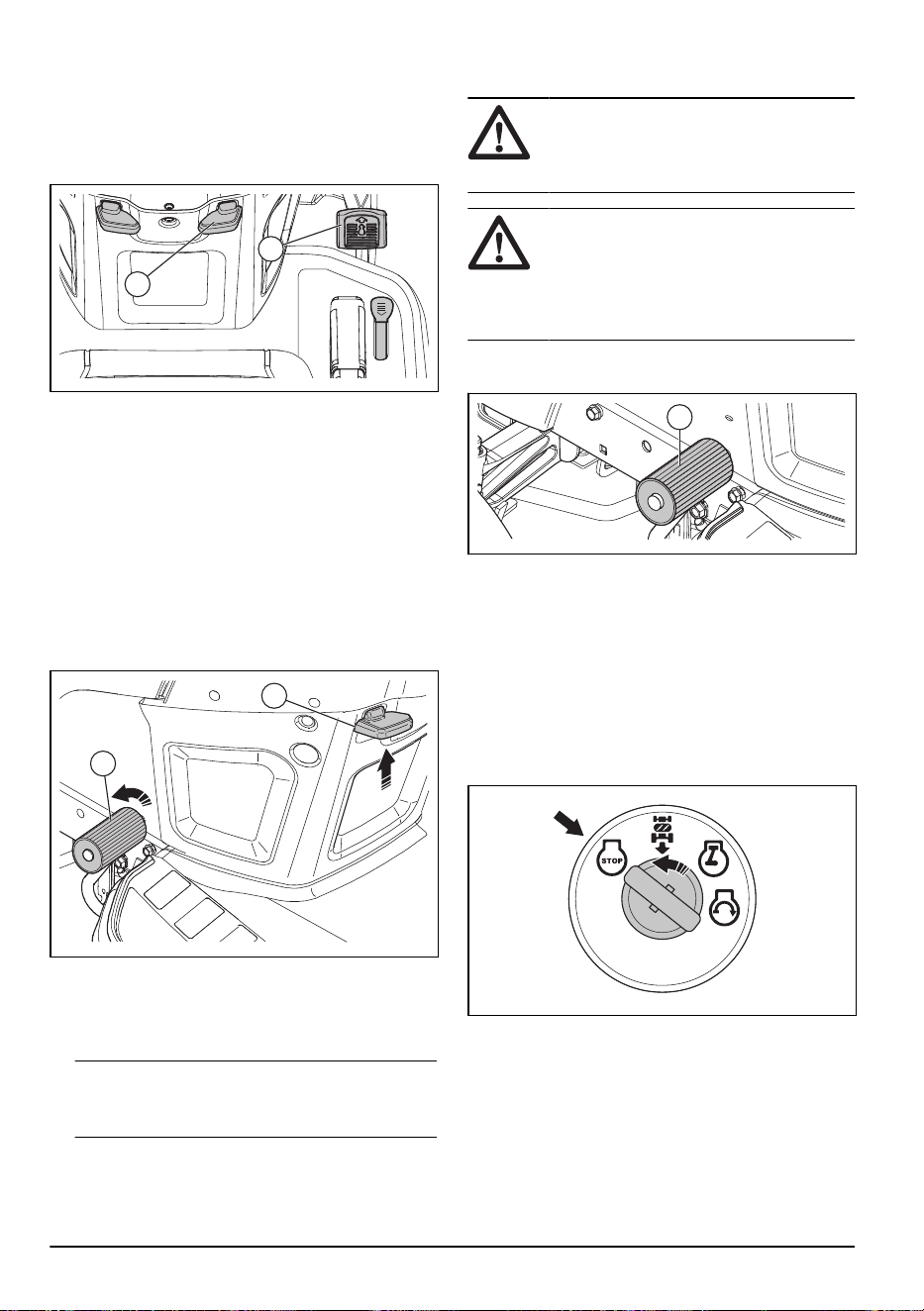
automáticamente si las condiciones de control de
crucero no son satisfactorias.
1. Presione el pedal de mando de avance (B).
Mantenga el pedal de mando de avance en una
posición que facilite alcanzar la velocidad correcta
para el terreno.
A
B
2. Tire de la palanca de control de crucero (A) hacia
arriba y sujétela mientras suelta el pedal de mando
de avance.
3. Suelte la palanca para acoplar el control de crucero.
4. Presione el pedal de freno o toque el pedal de
mando de avance para desacoplar el control de
crucero.
Para acoplar y desacoplar el freno de
estacionamiento
1. Para accionar el freno de estacionamiento, presione
el pedal de freno (A) completamente hasta la
posición más baja.
B
A
2. Con el pedal de freno presionado, tire hacia arriba
de la palanca del freno de estacionamiento (B).
3. Suelte el pedal de freno.
4. Suelte la palanca del freno de estacionamiento.
Tenga en cuenta:
Asegúrese de que el freno
de estacionamiento detenga la máquina de forma
segura.
5. Para soltar el freno de estacionamiento, pise el
pedal de freno.
Para detener el producto
ADVERTENCIA: Siempre detenga
la máquina, accione el freno de
estacionamiento y retire la llave de
encendido antes de alejarse del producto.
AVISO: El gas de escape del
motor caliente puede causar daños por
quemadura en el césped. Para evitar
daños por quemaduras en el césped,
siempre detenga el motor cuando detenga
el producto en zonas de césped.
1. Pise completamente el pedal de freno (A) hasta que
el producto se detenga por completo.
A
2. Desacople el equipo de corte. Consulte
Para acoplar
y desacoplar el equipo de corte en la página 57
.
3. Coloque el acelerador en la posición lenta y deje
que el motor funcione a régimen de ralentí durante
algunos minutos.
4. Coloque el equipo de corte en la posición de
transporte. Consulte
Para colocar el equipo de corte
en la posición de transporte o posición de corte en la
página 55
.
5. Gire la llave de encendido a la posición “STOP” y
retire la llave del encendido.
Para utilizar el control del acelerador
La eficiencia operativa del motor disminuye cuando el
motor funciona a una velocidad menor que la máxima.
La velocidad máxima proporciona el mejor rendimiento
del cortacésped.
56
2231 - 003 - 22.09.2023
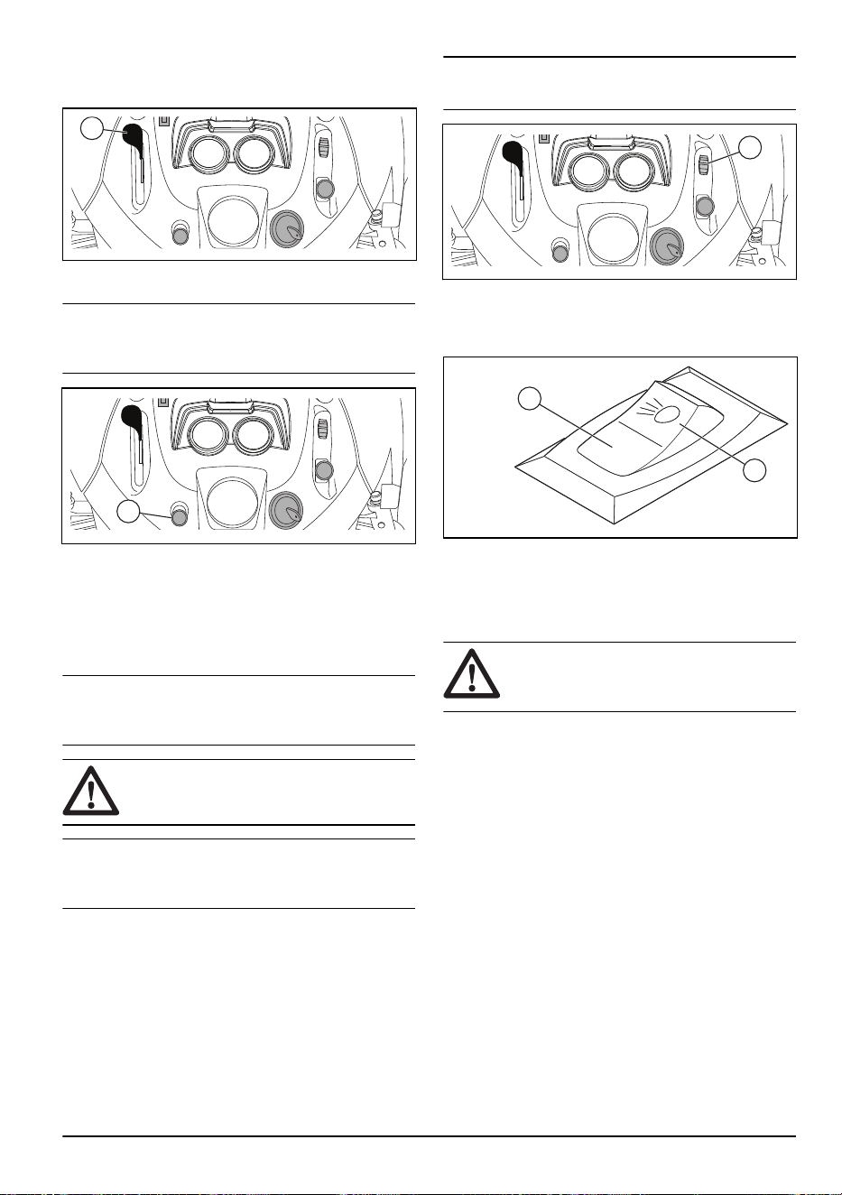
• Ajuste el control del acelerador (A) a la posición
"FULL” (MÁXIMO) para operar el motor a máxima
velocidad.
A
Para utilizar el estrangulador
Tenga en cuenta: Use el estrangulador para
arrancar el motor frío. No utilice el estrangulador para
arrancar un motor frío.
A
1. Retire la perilla (A) para acoplar el estrangulador.
2. Pulse la perilla (A) lentamente para desacoplar el
estrangulador.
Para utilizar el control de bloqueo de
diferencial
Tenga en cuenta:
El producto o el sistema
no están dañados si el bloqueo de diferencial está
acoplado durante un largo período de tiempo.
AVISO: No accione el bloqueo de
diferencial mientras el producto se mueve.
Tenga en cuenta: Si el bloqueo de diferencial
(A) está acoplado cuando gira, la hierba se puede
mover o cubrir con césped.
1. Detenga el producto y pulse el interruptor de
bloqueo del diferencial a la posición de "ON”
(ENCENDIDO).
2. Mueva el producto hacia delante. A medida que los
neumáticos traseros giran, el bloqueo del diferencial
se acopla.
Para desacoplar el bloqueo del diferencial:
• Presione el interruptor de bloqueo del diferencial a la
posición de "OFF” APAGADO.
Tenga en cuenta:
Si el bloqueo del diferencial
no se desacopla, dirija el producto de lado a lado.
A
Para usar el faro delantero
• Presione el interruptor de encendido/apagado a la
posición (A) para que el faro delantero se encienda.
A
B
• Presione el interruptor de encendido/apagado a la
posición (B) para apagar el faro.
Para acoplar y desacoplar el equipo de
corte
ADVERTENCIA:
No opere el equipo
de corte sin un deflector instalado en la
descarga de hierba.
El producto tiene un control de presencia del operador
(OPC). Cuando se aleje del asiento con el motor en
marcha y el equipo de corte acoplado, el motor se
detiene.
Manténgase por completo y en el centro del
asiento para asegurarse de que el motor funcione
2231 - 003 - 22.09.2023
57
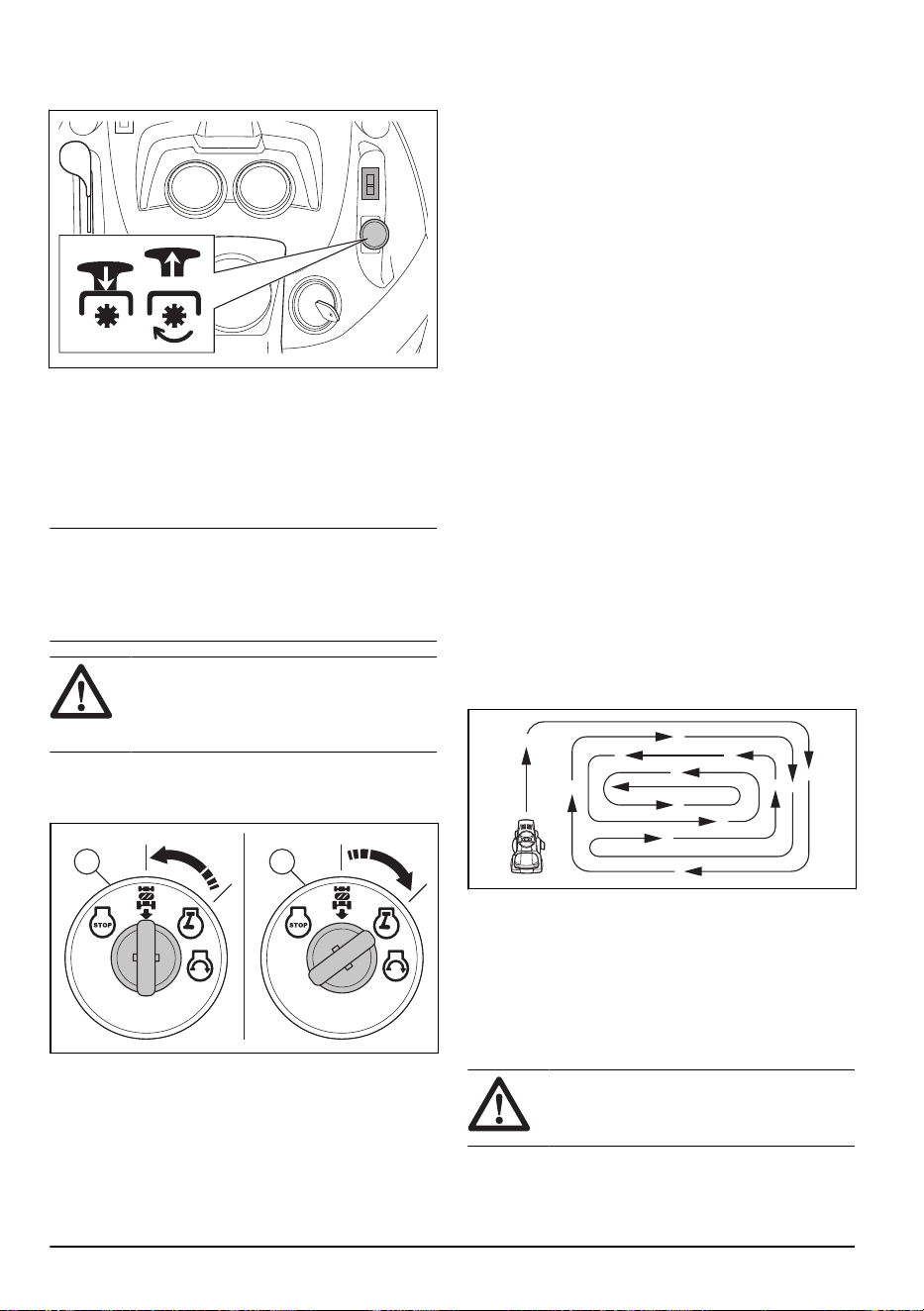
correctamente y de que no se detiene en terrenos
irregulares o en pendientes.
• Tire del botón de PTO hacia arriba para conectar el
equipo de corte.
• Presione el botón de PTO para desacoplar el equipo
de corte.
Para utilizar el sistema de
funcionamiento en reversa (ROS)
Tenga en cuenta: Si intenta retroceder con el
producto cuando el equipo de corte está acoplado, el
motor se detiene inmediatamente. Haga que el ROS se
desplace hacia atrás con el producto cuando el equipo
de corte esté acoplado.
ADVERTENCIA: Antes y mientras
conduce el producto hacia atrás, mire hacia
abajo y detrás del producto para garantizar
la seguridad de los demás.
1. Para acoplar el ROS, gire la llave de encendido en
el sentido contrario a las agujas del reloj hasta la
posición de ROS encendido (A).
BA
2. Presione lentamente el pedal de mando de reversa
para iniciar el movimiento.
3. Para desacoplar el ROS, gire la llave de encendido
en el sentido de las agujas del reloj hasta la posición
“ON” del motor (B).
Para conseguir un buen resultado de
corte
• Para un mejor funcionamiento, realice el
mantenimiento del producto con regularidad como
se indica en el programa de mantenimiento.
Consulte
Programa de mantenimiento en la página
60
.
• No corte el césped húmedo. El césped húmedo
puede causar un mal resultado de corte.
• No utilice las cadenas para neumáticos cuando
conecte el equipo de corte al producto.
• Asegúrese de que el equipo de corte esté nivelado.
Consulte
Para ajustar el paralelismo del equipo de
corte en la página 68
.
• Si el césped está largo, comience con una altura de
corte alta y disminúyala gradualmente.
• Avance con el producto a baja velocidad si el
césped es alto y grueso.
• Utilice la aceleración máxima cuando corte el
césped.
• Corte el césped en un patrón irregular.
• Utilice el lado izquierdo del equipo de corte cuando
corte cerca de árboles, arbustos o caminos. La hoja
corta a aproximadamente 15mm del lado del equipo
de corte.
• Cuando corte áreas grandes, mueva el producto
hacia la derecha durante 1 o 2 vueltas alrededor
del área de trabajo. Este procedimiento mantendrá
la descarga del césped lejos de arbustos, cercas y
entradas de garajes. Después de aproximadamente
2 vueltas alrededor del área de trabajo, corte en el
sentido opuesto.
• Para obtener los mejores resultados de corte, corte
el césped con frecuencia.
Para poner el producto en modo de
rueda libre
Si es necesario mover o remolcar el producto sin ayuda
del motor, debe poner el producto en el modo de rueda
libre.
ADVERTENCIA:
No coloque el
producto en modo de rueda libre en una
pendiente.
58 2231 - 003 - 22.09.2023

• Presione la palanca de control de rueda libre (A)
para poner el producto en modo de conducción
A
• Presione la palanca de control de rueda libre (A)
para poner el producto en modo de rueda libre.
Mantenimiento
Introducción
ADVERTENCIA: Lea detenidamente
el capítulo de seguridad antes de realizar
mantenimiento en el producto.
2231 - 003 - 22.09.2023 59

Programa de mantenimiento
Programa de mantenimiento Antes de
cada
uso
En inter-
valos de
8horas
En inter-
valos de
25horas
En inter-
valos de
50horas
En inter-
valos de
100ho-
ras
Cada
tempora-
da
Antes
del al-
macena-
miento
Producto Compruebe la función del
freno.
X X
Compruebe la presión de
los neumáticos.
X X
Para verificar el control
de presencia del operador
(OPC).
X
Para verificar el sistema
de funcionamiento en re-
versa (ROS).
X
Compruebe si hay sujeta-
dores sueltos.
X X X
Examine las hojas para
detectar si hay desgaste
o daños.
X
2
Lubrique el producto.
Consulte
Programa de lu-
bricación en la página
61
.
X X
Compruebe el nivel de la
batería.
X
Limpie la batería y los ter-
minales.
X X
Limpie las piezas de la
placa de dirección. Con-
sulte
Para limpiar el pro-
ducto en la página 62
.
X
Revise el ventilador de re-
frigeración del transeje.
X
Asegúrese de que el
equipo de corte esté nive-
lado.
X
Revise las correas enV. X
2
Examine las hojas con mayor frecuencia si corta en áreas donde hay arena y tierra.
60 2231 - 003 - 22.09.2023

Programa de mantenimiento Antes de
cada
uso
En inter-
valos de
8horas
En inter-
valos de
25horas
En inter-
valos de
50horas
En inter-
valos de
100ho-
ras
Cada
tempora-
da
Antes
del al-
macena-
miento
Motor Revise el nivel de aceite
del motor.
X X
Cambie el aceite del mo-
tor (modelos con filtro de
aceite).
X
1
X
Cambie el aceite del mo-
tor (modelos sin filtro de
aceite).
X
1
X
Limpie el filtro de aire. X
3
Limpie la pantalla de aire. X
3
Realice una inspección
del silenciador y el apaga-
chispas.
X
Reemplace el filtro de
aceite (si está equipado).
X
1
X
Limpie las aletas de refri-
geración del motor.
X
3
Reemplace la bujía. X X
Reemplace el cartucho de
papel del filtro de aire.
X
3
Reemplazar el filtro de
combustible
X
Revise el silenciador.
Consulte
Para revisar el
silenciador en la página
73
.
X
Programa de lubricación
AVISO: No lubrique los puntos de
los pivotes que tienen cojinetes de nailon
especiales. Los lubricantes pegajosos
pueden hacer que se adhiera suciedad. La
suciedad reduce la vida útil de los cojinetes
de nailon especiales. Si es necesario
lubricar los cojinetes de nailon, utilice solo
una pequeña cantidad de lubricante seco.
1
Hágalo con mayor frecuencia cuando opere con una carga pesada, en temperatura ambiente elevada o en
condiciones de suciedad.
1
Hágalo con mayor frecuencia cuando opere con una carga pesada, en temperatura ambiente elevada o en
condiciones de suciedad.
3
Hágalo con mayor frecuencia si opera en condiciones de suciedad.
3
Hágalo con mayor frecuencia si opera en condiciones de suciedad.
1
Hágalo con mayor frecuencia cuando opere con una carga pesada, en temperatura ambiente elevada o en
condiciones de suciedad.
3
Hágalo con mayor frecuencia si opera en condiciones de suciedad.
3
Hágalo con mayor frecuencia si opera en condiciones de suciedad.
2231 - 003 - 22.09.2023 61
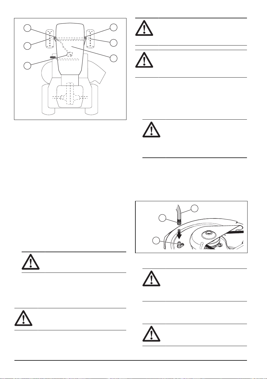
A
A
B
A
A
A
A. Lubricación general. Lubrique la conexión de engrase
del eje, el cojinete de la rueda delantera y los dientes
del engranaje de la parte de la dirección.
B. Lubricación del motor. Consulte
Para lubricar el
motor en la página 71
.
Tractor
Para limpiar el producto
No utilice una manguera de jardín ni una arandela de
presión para limpiar la superficie, excepto el puerto
de lavado. Mantenga el agua fuera del motor y de la
transmisión. El agua en el motor o en la transmisión
puede reducir la vida útil del producto. Utilice aire
comprimido o una sopladora de hojas para quitar la
hierba, las hojas y la basura.
• Limpie todo el material no deseado del motor, la
batería, el asiento y otras partes del producto.
• Limpie la contaminación de la placa de dirección. La
contaminación limita el movimiento del eje del pedal
de freno/embrague, provoca que la correa se suelte
y disminuye el movimiento hacia delante.
AVISO:
Evite todos los puntos de
enganche y las partes móviles.
• Mantenga las superficies y las ruedas libres de
gasolina, aceite y otros.
• Utilice cera automotriz para prevenir el daño a las
superficies.
Para utilizar el puerto de lavado del equipo
ADVERTENCIA:
Instale los pernos y
las contratuercas en todos los agujeros del
equipo de corte.
ADVERTENCIA: Reemplace el
montaje de lavado roto o faltante
inmediatamente antes de utilizar el equipo
de corte.
ADVERTENCIA: Un puerto de
lavado roto o faltante puede causarle
lesiones a usted o a otras personas debido
a objetos que pueden salir eyectados.
El producto cuenta con puerto de lavado como parte del
sistema de lavado del equipo. Úselo después de cada
operación.
1. Lleve el producto a un área nivelada y despejada
cerca de una manguera de jardín conectada a una
salida de agua.
AVISO: Asegúrese de que el
conducto expulsión se encuentre lejos
de edificios, vehículos estacionados y
otros elementos de valor. Retire el
conducto colector o la cubierta para el
triturado si es necesario.
2. Asegúrese de que el control del embrague
de acoplamiento se encuentre en la posición
“DISENGAGED” (Desacoplada).
3. Detenga el motor y acople el freno de
estacionamiento.
4. Coloque el adaptador de boquilla (A) en el extremo
de la manguera de jardín (B).
A
C
B
5. Conecte el adaptador de boquilla en el puerto de
lavado (C) en el lado izquierdo del equipo de corte.
AVISO:
Tire de la manguera
de jardín para asegurarse de que
el adaptador de boquilla esté
completamente conectado al puerto de
lavado del equipo.
6. Inicie el suministro de agua.
7. Arranque el motor y coloque el acelerador en la
posición “Rápido”.
AVISO:
Asegúrese de que el área
esté despejada y que no haya niños en
la zona cuando limpie el equipo de corte.
62 2231 - 003 - 22.09.2023

8. Siéntese en el asiento y conecte el equipo de corte.
Deje que el equipo de corte funcione hasta que esté
limpio.
9. Desconecte el equipo de corte y detenga el motor.
10. Detenga el suministro de agua.
11. Desconecte la manguera de jardín y el adaptador de
boquilla del puerto de lavado del equipo.
12. Mueva el producto a una zona seca.
13. Acople el equipo de corte y deje que funcione hasta
que esté seco.
Para ajustar el cable del acelerador
El acelerador se configura en la fábrica y no debería ser
necesario el ajuste. Si es necesario realizar un ajuste,
consulte el manual del motor.
Para ajustar el estrangulador
El estrangulador se configura en la fábrica y no debería
ser necesario el ajuste. Si es necesario realizar un
ajuste, consulte el manual del motor.
Para revisar los enclavamientos y los relés
Tenga en cuenta: Los cables sueltos o dañados
pueden hacer que su producto funcione de forma
insatisfactoria, que deje de funcionar o evitar que
arranque.
• Examine los cables.
Para reemplazar la luz LED del faro
1. Abra la cubierta del motor.
2. Desconecte el arnés de cables de la luz LED.
3. Quite los tornillos, la luz LED, el reflector y la lente.
4. Instale una nueva luz LED.
5. Instale el reflector y la lente con los tornillos.
6. Conecte el arnés de cables a la luz LED.
7. Cierre la cubierta del motor.
Para comprobar los neumáticos
Tenga en cuenta:
Para sellar los orificios de los
neumáticos e impedir los neumáticos desinflados debido
a fugas lentas, obtenga sellador de su concesionario
de piezas locales. El sellador de neumáticos también
previene la podredumbre en seco y la corrosión.
• Asegúrese de que la presión del aire de todos los
neumáticos sea correcta (consulte los lados de los
neumáticos para ver el PSI correcto).
• Mantenga los neumáticos libres de gasolina, aceite
o productos químicos para el control de insectos que
pueden causar daños al caucho.
• Mantenga los neumáticos lejos de palos, piedras,
surcos, objetos afilados y otros objetos peligrosos
que pueden causar daño a los neumáticos.
Para reparar los neumáticos
1. Levante el eje delantero y apóyelo de forma segura.
AVISO: Eleve y apoye un eje a la
vez.
2. Retire la tapa de polvo (A), el sujetador en E (B), la
arandela (C) y la llave cuadrada (D).
B
C
A
D
Tenga en cuenta: Solo hay llaves cuadradas
en las ruedas traseras.
3. Quite la rueda del eje.
4. Retire el neumático de la rueda.
5. Repare el neumático.
Tenga en cuenta:
Utilice sellador de
neumáticos para sellar los orificios en el neumático.
El sellador de neumáticos también previene la
podredumbre en seco y la corrosión.
6. Instale el neumático en la rueda.
7. Instale la rueda, la arandela, la llave cuadrada y
el sujetador en E en el eje. Asegúrese de que el
sujetador en E esté instalado correctamente en la
ranura del eje.
8. Instale la tapa de polvo.
Para examinar las correas en V
Las correas no son ajustables.
• Examine las correas en V en busca de deterioro o
desgaste después de cada intervalo de 100horas
de funcionamiento.
• Sustituya las correas en V si comienzan a moverse
porque están demasiado desgastadas.
Para realizar mantenimiento en el ventilador
de refrigeración del transeje.
AVISO: No limpie el ventilador o la
transmisión mientras el motor esté en
2231 - 003 - 22.09.2023 63
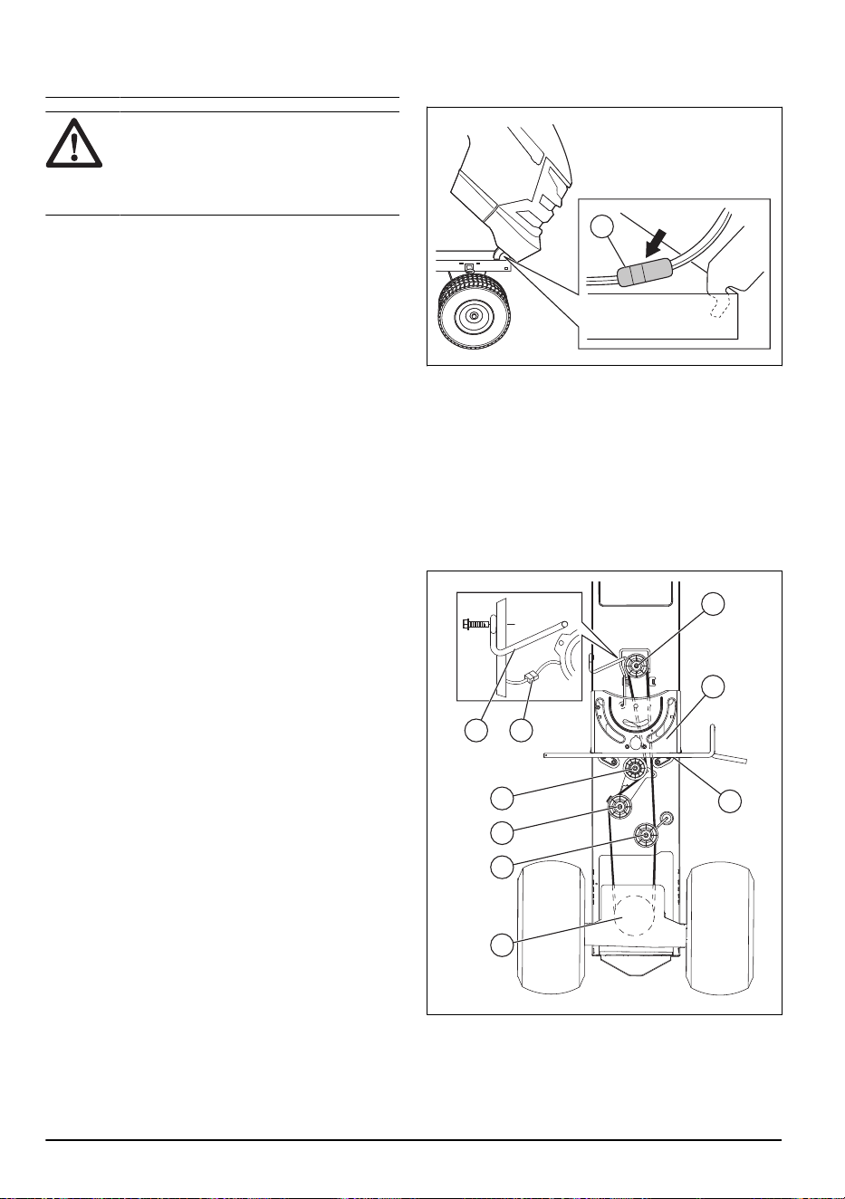
marcha o mientras la transmisión esté
caliente.
AVISO: No utilice lavadores a alta
presión ni limpieza a vapor. Podría entrar
agua a los cojinetes y las conexiones
eléctricas y causar corrosión, lo que puede
dañar el producto.
Para mantener la transmisión fría, mantenga limpios el
ventilador de la transmisión y las aletas de refrigeración.
• Antes de limpiar con agua, limpie con un cepillo.
Quite los cortes de pasto y la suciedad que se
encuentren en el ventilador del transeje y las aletas
de enfriamiento y alrededor de estos.
• Examine el ventilador de refrigeración para
asegurarse de que las cuchillas del ventilador estén
limpias y no estén dañadas.
Para examinar el líquido de la bomba del
transeje
• Asegúrese de que no haya fugas de líquido de la
bomba del transeje.
• Consulte al centro o departamento de servicio
autorizado más cercano si existen fugas de líquido
de la bomba del transeje.
Para ajustar la convergencia y la inclinación
de la rueda delantera
La convergencia y la inclinación de la rueda delantera
se ajustan correctamente en la fábrica. La convergencia
y la inclinación de la rueda delantera no son ajustables.
• Consulte a un centro de servicio autorizado si la
convergencia o inclinación ajustada de fábrica está
dañada.
Para reemplazar el fusible
Esta máquina tiene dos fusibles automotrices. El
sujetador del fusible está ubicado detrás del panel.
1. Sostenga el portafusibles y tire del fusible quemado.
2. Coloque un fusible nuevo en el portafusibles.
Para quitar e instalar la cubierta del motor y el
conjunto de parrilla
A
1. Levante la cubierta del motor.
2. Desconecte el conector de cables de los faros (A).
3. Manténgase en frente del tractor. Sostenga la
cubierta del motor desde los lados. Incline la
cubierta del motor en la dirección del motor y
levántela para extraerlo del producto.
4. Vuelva a instalar todo en el orden inverso.
Para sustituir la correa de transmisión de
movimiento
G
H
I
F
E
D
C
AB
Estacione el producto sobre una superficie nivelada.
Acople el freno de estacionamiento. Consulte la etiqueta
de instalación de la correa en la parte inferior del
reposapiés izquierdo.
64
2231 - 003 - 22.09.2023

1. Retire la correa.
a) Retire el cortacésped. Consulte
Para quitar e
instalar el equipo de corte en la página 67
.
Tenga en cuenta: Tenga cuidado con
la correa de transmisión de movimiento y la
posición de las guías de la correa y los
sujetadores.
b) Desconecte el arnés de cableado del embrague
(A).
c) Retire el eslabón anti rotación (B) en el lado
derecho del producto.
d) Retire la correa del rodillo inmóvil (C) y el rodillo
de embrague (D).
e) Retire la correa del rodillo del tramo central (E).
f) Tire la correa hacia la parte trasera del producto.
Retire cuidadosamente la correa de la polea
de transmisión de entrada y por encima de las
cuchillas del ventilador de refrigeración (F).
g) Retire la correa de la polea del motor y alrededor
del embrague eléctrico (G).
h) Mueva la correa a la parte trasera del producto
y fuera de la placa de dirección (H). Retire del
producto.
2. Instale la nueva correa desde la parte trasera del
producto a la parte delantera, y por encima de la
placa de dirección (H) y del eje del pedal del freno
de embrague (I).
a) Tire la correa a la parte delantera del producto
e instale la correa alrededor del embrague
eléctrico y sobre la polea del motor (G).
b) Tire la correa hacia la parte trasera del producto.
c) Instale cuidadosamente la correa por debajo,
alrededor del ventilador de refrigeración de
transmisión y sobre la polea de entrada.
Asegúrese de que la correa esté dentro del
retenedor de la correa.
d) Instale la correa en el rodillo del tramo central
(E).
e) Instale la correa a través del rodillo inmóvil (C) y
el rodillo de embrague (D).
f) Instale el enlace anti rotación (B) en el lado
derecho del producto y apriete completamente.
g) Conecte el arnés del embrague (A).
h) Asegúrese de que la correa se encuentre en
todas las ranuras de la polea y en todas las
guías y sujeciones de la correa.
i) Instale el cortacésped. Consulte
Para quitar e
instalar el equipo de corte en la página 67
Batería
Para limpiar la batería y los terminales
La corrosión y la suciedad de la batería y los terminales
pueden hacer que la batería pierda energía.
1. Extraiga la protección del terminal.
2. Desconecte el cable NEGRO de la batería.
3. Desconecte el cable ROJO de la batería y retire la
batería del producto.
4. Rocíe la batería con agua y déjela secar.
5. Limpie los bornes y los extremos del cable de la
batería con un cepillo de alambre.
6. Lubrique los terminales con grasa o un producto
equivalente.
7. Instale la batería. Consulte
Para conectar la batería
en la página 52
.
Para reemplazar la batería
ADVERTENCIA: No corte las
terminales de la batería. No permita que
las herramientas u otros objetos entren en
contacto con ambas terminales al mismo
tiempo.
ADVERTENCIA: Antes de conectar
la batería, quítese las pulseras de metal, los
relojes, anillos, y otros.
1. Levante la cubierta a una posición elevada.
2. Retire la tapa del terminal (C).
3. Desconecte el cable de tierra (A) negro (negativo)
quitando el perno y la tuerca.
ADVERTENCIA: El terminal
del cable negro (negativo) se debe
desconectar primero.
4. Desconecte el cable de batería (B) rojo (positivo).
5. Retire con cuidado la batería del producto.
6. Instale una batería nueva en la misma posición que
en la batería antigua.
7. Instale la cubierta del terminal (C).
8. Conecte el cable de batería (B) rojo (positivo) y
apriete el perno y la tuerca.
ADVERTENCIA:
El terminal del
cable rojo (positivo) se debe conectar
primero para evitar chispas de una
conexión a tierra accidental.
9. Conecte el cable (A) negro (negativo) y apriete el
perno y tuerca.
2231 - 003 - 22.09.2023
65
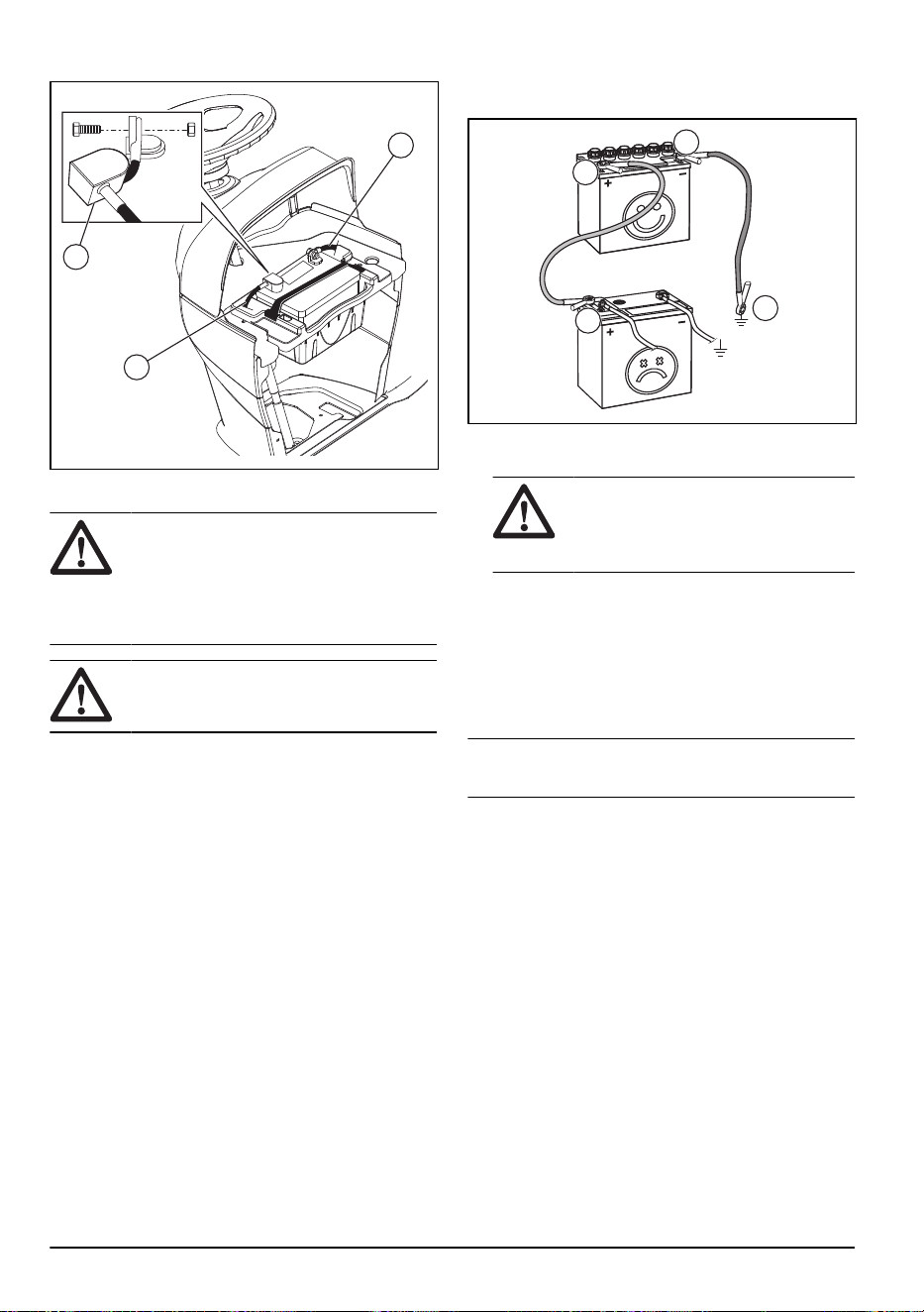
10. Baje la cubierta.
A
C
B
Para conectar los cables de puente
ADVERTENCIA: Existe riesgo de
explosión debido a los gases explosivos
procedentes de la batería. No conecte el
terminal negativo de la batería cargada al
terminal negativo de la batería con poca
carga ni cerca de este.
AVISO: No utilice la batería de su
producto para arrancar otros vehículos.
1. Conecte un extremo del cable rojo de la batería al
terminal POSITIVO (+) (A) de la batería con poca
carga.
B
A
C
D
2. Conecte el otro extremo del cable rojo de la batería
al terminal POSITIVO (+) (B) de la batería cargada.
ADVERTENCIA: No deje que los
extremos del cable rojo de la batería
hagan contacto con el chasis, ya que
esto provocaría un cortocircuito.
3. Conecte un extremo del cable negro de la batería al
terminal NEGATIVO (-) (C) de la batería cargada.
4. Conecte el otro extremo del cable negro de la
batería a una CONEXIÓN A TIERRA DEL CHASIS
(D), lejos del depósito de combustible y de la
batería.
Para retirar los cables de puente
Tenga en cuenta:
Quite los cables de puente en
la secuencia opuesta a cómo los conectó.
1. Quite el cable NEGRO del chasis.
2. Quite el cable NEGRO de la batería totalmente
cargada.
3. Quite el cable ROJO de las 2 baterías.
66
2231 - 003 - 22.09.2023

Equipo de corte
Para quitar e instalar el equipo de corte
A
G
H
I
E B
F
D C
1. Estacione el producto en una superficie nivelada y
accione el freno de estacionamiento.
2. Desconecte el equipo de corte y detenga el motor.
3. Coloque la palanca de elevación del accesorio en la
posición más baja.
4. Retire la correa de transmisión del equipo de corte
de la polea del embrague eléctrico (A).
5. Retire la contratuerca (B), la tuerca (C), el buje (D) y
desconecte el eslabón delantero (E) del soporte (F)
en el chasis.
6. Retire los sujetadores (G) y las arandelas y
desconecte los 2brazos de suspensión (H) del
chasis.
7. Retire los sujetadores y las arandelas y desconecte
los eslabones de elevación traseros (I) del equipo de
corte.
ADVERTENCIA: Cuando los
eslabones de elevación traseros están
desconectados del equipo de corte, la
palanca de elevación del accesorio se
acciona por resorte. Sujete firmemente
la palanca de elevación del accesorio si
cambia su posición.
8. Retire el equipo de corte del producto.
9. Instale el equipo de corte en el orden inverso.
Asegúrese de que el lado de descarga esté en
el lado derecho del producto. Asegúrese de que
la correa de transmisión del equipo de corte esté
instalada correctamente. Consulte
Para retirar la
correa de transmisión del equipo de corte en la
página 70
.
Tenga en cuenta: Los brazos de suspensión
deben estar en la posición de avance cuando mueve
el equipo de corte debajo del producto.
Para instalar la espada antioscilación
1. Desde el lado derecho del equipo de corte, coloque
el extremo de 90° de la espada antioscilación (A) en
el orificio del soporte del transeje (B).
A
B
D
E
C
2. Coloque el extremo integrado de la arandela (C) de
la espada antioscilación en el orificio del soporte
trasero, que se encuentra en el lado derecho del
equipo de corte. Mueva el equipo de corte si es
necesario.
2231 - 003 - 22.09.2023
67
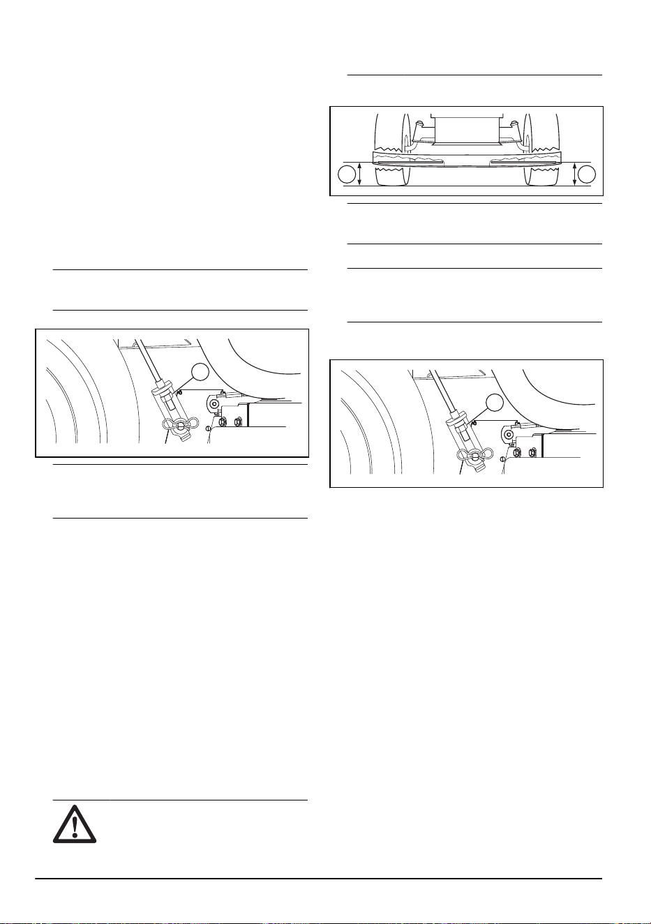
3. Instale la arandela (D) y el sujetador (E).
Para ajustar el paralelismo del equipo de corte
Para realizar un ajuste visual de lado a lado del equipo
de corte
Si la altura de corte no es la misma en los lados
derecho e izquierdo de la máquina, se puede ajustar
la altura de corte. Ajuste la altura de corte en el lado del
equipo de corte que tenga la menor altura de corte.
1. Asegúrese de que los neumáticos estén totalmente
inflados.
2. Estacione el producto sobre una superficie nivelada.
3. Diríjase al costado del equipo de corte que tenga la
altura de corte más baja.
Tenga en cuenta: Algunos modelos solo
tienen ajuste del lado izquierdo.
4. Ajuste la altura de corte con una llave de 3/4".
A
Tenga en cuenta: Cada vuelta completa de
la tuerca de ajuste cambia la altura del equipo de
corte a aproximadamente 4,7mm (3/16").
a) Gire la tuerca de ajuste de elevación (A) hacia la
izquierda para bajar el equipo de corte.
b) Gire la tuerca de ajuste de elevación (A) hacia la
derecha para subir el equipo de corte.
5. Corte un poco de pasto y examine los resultados.
Ajuste si es necesario.
Para realizar un ajuste preciso de lado a lado del equipo
de corte
1. Asegúrese de que los neumáticos estén totalmente
inflados.
2. Estacione el producto sobre una superficie nivelada.
3. Coloque el equipo de corte en la posición de
transporte. Consulte
Para colocar el equipo de corte
en la posición de transporte o posición de corte en la
página 55
.
4. Gire las puntas externas de la cuchilla para
alinearlas con el equipo de corte de lado a lado.
ADVERTENCIA:
Las cuchillas
del equipo de corte están afiladas y
pueden causar lesiones. Use guantes
protectores.
5. Mida la distancia (B) desde el borde inferior de la
hoja hasta el suelo en el lado izquierdo y derecho.
B B
Tenga en cuenta: La distancia debe ser igual
en los dos lados.
6. Ajuste la altura de corte con una llave de 3/4".
Tenga en cuenta: Cada vuelta completa de
la tuerca de ajuste de elevación cambia la altura de
corte en 4,7mm (3/16").
a) Gire la tuerca de ajuste de elevación (A) hacia la
izquierda para bajar el equipo de corte.
A
b) Gire la tuerca de ajuste de elevación (A) hacia la
derecha para subir el equipo de corte.
7. Mida nuevamente la distancia. Ajuste hasta que los
2 lados sean iguales.
8. Corte un poco de pasto y examine los resultados.
Ajuste si es necesario.
Para realizar un ajuste de adelante hacia atrás del
equipo de corte
El equipo de corte debe estar nivelado de lado a lado
antes de realizar el ajuste de la parte delantera respecto
de la parte trasera. Consulte
Para realizar un ajuste
visual de lado a lado del equipo de corte en la página
68
.
1. Asegúrese de que los neumáticos estén totalmente
inflados.
2. Estacione el producto sobre una superficie nivelada.
3. Coloque el equipo de corte en la posición de
transporte. Consulte
Para colocar el equipo de corte
en la posición de transporte o posición de corte en la
página 55
.
4. Gire las hojas hasta que apunten hacia delante.
68
2231 - 003 - 22.09.2023
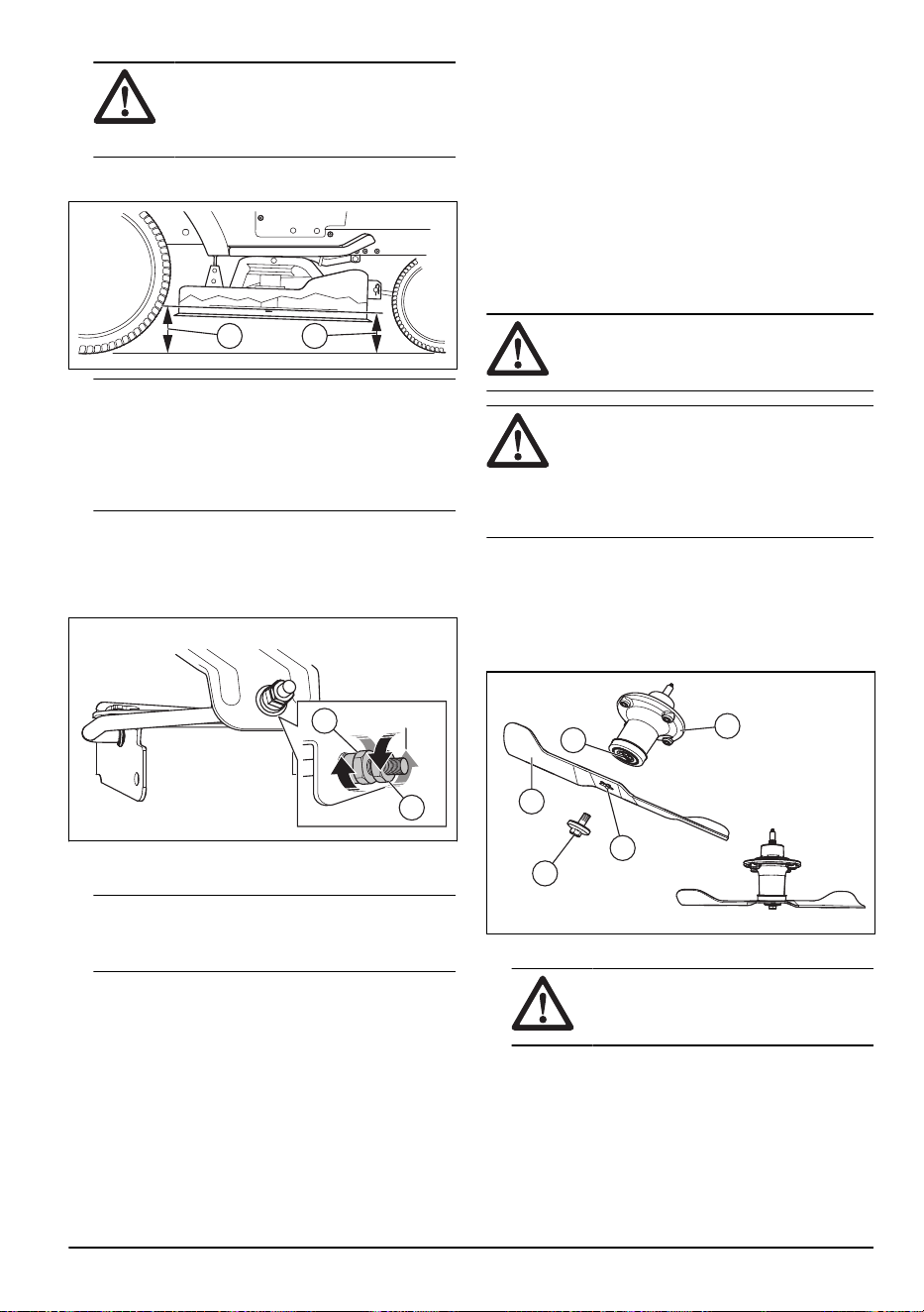
ADVERTENCIA: Las cuchillas
del equipo de corte están afiladas y
pueden causar lesiones. Use guantes
protectores.
5. Mida la distancia hasta el suelo en los extremos
delantero (B) y trasero (A) de la cuchilla.
BA
Tenga en cuenta: Para obtener los mejores
resultados de corte, las hojas deben estar ajustadas
hasta que el extremo delantero esté entre 3,1 y
12,7mm (1/8 y 1/2") más bajo que el extremo
trasero cuando el equipo de corte esté en su
posición más alta.
6. Vaya a la parte delantera de la máquina para hacer
un ajuste.
7. Con una llave de 11/16", afloje la tuerca de
inmovilización (C) para despejar la tuerca de ajuste
de elevación (D).
D
C
8. Ajuste la altura del equipo de corte con una llave de
3/4".
Tenga en cuenta:
Cada vuelta completa de
la tuerca de ajuste de elevación cambia la altura del
equipo de corte en 3,1mm (1/8").
a) Gire la tuerca de ajuste de elevación hacia el
sentido contrario de las agujas del reloj para
bajar el equipo de corte.
b) Gire la tuerca de ajuste de elevación en el
sentido a las agujas del reloj para elevar el
equipo de corte.
9. Mida nuevamente la distancia delantera y trasera.
10. Ajuste hasta que el extremo delantero de la hoja
esté de 3,1mm a 12,7mm (de 1/8” a 1/2”) más bajo
que el extremo trasero.
11. Sujete la tuerca de ajuste de elevación en su
posición con la llave y apriete la tuerca de
inmovilización.
Para sustituir las hojas
Para obtener mejores resultados, mantenga las
cuchillas de corte afiladas. Sustituya las cuchillas
dobladas o dañadas.
ADVERTENCIA: Las cuchillas del
equipo de corte están afiladas y pueden
causar lesiones. Use guantes protectores.
AVISO: Utilice solo una cuchilla de
reemplazo aprobada por el fabricante. Es
peligroso usar una cuchilla no aprobada
por el fabricante del producto. Esto puede
causar daños en el producto y anular la
garantía.
1. Coloque el equipo de corte en la posición de
transporte. Consulte
Para colocar el equipo de corte
en la posición de transporte o posición de corte en la
página 55
.
2. Quite el perno (A) girándolo hacia el sentido
contrario a las agujas del reloj y quite la hoja (B).
A
D
C
E
B
3. Instale la cuchilla nueva o afilada y el perno.
AVISO:
El orificio central (C) en la
hoja se debe alinear con la estrella (D)
en el conjunto del mandril (E).
4. Apriete el perno entre 62 y 75Nm (entre 45 y 55lb-
pie).
2231 - 003 - 22.09.2023
69

Para retirar la correa de transmisión del
equipo de corte
A
C
B
D
1. Estacione el producto en una superficie nivelada y
accione el freno de estacionamiento.
2. Coloque la palanca de elevación del accesorio en la
posición más baja.
3. Retire las cubiertas del mandril (A y B).
4. Retire la suciedad y los recortes de césped
alrededor de los mandriles y de la superficie superior
del equipo.
5. Gire las poleas con la mano y tire de la correa (C)
para retirarla de la ranura de las poleas.
6. Retire la correa de alrededor del embrague eléctrico
(D) del eje del motor.
Para instalar la correa de transmisión del
equipo de corte
Tenga en cuenta: Para facilitar la instalación de
la correa de transmisión del equipo de corte, consulte la
etiqueta de información que se encuentra en el equipo
de corte.
1. Asegúrese de que el resorte del equipo (A) esté
conectado al perno de anillo (B) en el brazo guía.
A
B
2. Coloque la correa en todas las poleas excepto la
polea del lado izquierdo del mandril.
3. Instale la correa desde la parte trasera de la polea
del mandril del lado izquierdo.
4. Gire la polea del mandril del lado izquierdo para tirar
de la correa en la ranura de la polea del mandril del
lado izquierdo.
70
2231 - 003 - 22.09.2023

5. Consulte la etiqueta de información que se
encuentra en el equipo de corte para asegurarse de
que la correa esté instalada correctamente.
AVISO: Asegúrese de que la correa
no esté torcida.
6. Ajuste la tensión de la correa hasta que el resorte
del equipo se extienda a una longitud de 12,95cm
(5,1in) en la altura de corte más baja.
D
C
a) Afloje la tuerca de ajuste interior (C).
b) Gire la tuerca de ajuste exterior (D) hacia la
derecha para aumentar la tensión o hacia la
izquierda con el fin de disminuir la tensión.
c) Cuando la tensión sea correcta, apriete la tuerca
de ajuste interior completamente.
7. Instale las cubiertas del mandril.
Para ajustar las ruedas de apoyo
Las ruedas de apoyo mantienen el equipo de corte en la
posición correcta sobre el suelo y evitan el corte al ras
del césped en la mayoría de las condiciones del terreno.
Las ruedas de apoyo están correctamente ajustadas
cuando están un poco separadas del suelo y el equipo
de corte está a la altura de corte requerida.
1. Estacione el producto en una superficie nivelada y
detenga el motor.
2. Ajuste el producto hasta la altura de corte requerida.
Consulte
Ajuste de la altura de corte en la página
55
.
3. Retire la tuerca, el perno, la arandela y la rueda de
apoyo.
4. Instale la rueda de apoyo, el perno, la arandela y la
tuerca en la posición correcta.
5. Ajuste todas las ruedas de apoyo e instálelas en el
mismo procedimiento.
Motor
Para lubricar el motor
Use solo un aceite detergente de alta calidad calificado
con la clasificación SJ-SN de servicio de API. El grado
de viscosidad SAE del aceite se refiere a la temperatura
correcta para el funcionamiento.
-20 0 30 40
80
100
-30
-20 0
20 30 40
F
C
32
-10
10
60
5W-30
SAE 30
Tenga en cuenta:
Los aceites de viscosidad
múltiple (5W30, 10W30, etc.) ayudan a que el motor
arranque fácilmente en climas fríos, pero genera un
mayor consumo de aceite cuando se utilizan en
temperaturas superiores a los 0°C/32°F. Compruebe
el nivel de aceite del motor frecuentemente para evitar
posibles daños al motor causados por el bajo nivel de
aceite.
• Cambie el aceite a intervalos de 50horas de
funcionamiento. Si el producto no se utiliza durante
50horas en un año, cambie el aceite un mínimo de
una vez al año.
• Compruebe el nivel del aceite del cárter antes de
arrancar el motor y después de cada ocho (8) horas
de funcionamiento.
• Apriete la tapa/varilla de llenado de aceite cada vez
que realice una comprobación del nivel de aceite.
2231 - 003 - 22.09.2023
71
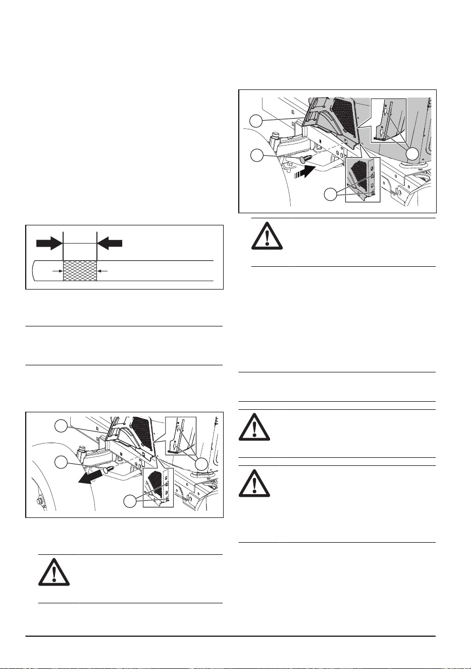
Para revisar el nivel de aceite del motor
El motor del producto se llena con aceite del motor a
una temperatura ambiente superior a 0°C (32°F). Para
la operación a una temperatura ambiente inferior a 0°C
(32°F), utilice el aceite del motor correcto para facilitar
el arranque del producto. Consulte .
1. Estacione el producto en un terreno plano.
2. Retire la tapa de llenado de aceite y la varilla de
nivel y límpiela con un paño.
3. Ponga la varilla de nivel en el tubo de llenado de
aceite. No gire la tapa de llenado de aceite hacia el
tubo de llenado de aceite.
4. Quité la varilla de nivel. Utilice el calibrador en la
varilla de nivel para examinar el nivel de aceite del
motor. Si es necesario, agregue aceite del motor
hasta alcanzar la marca de "FULL” (Lleno) en la
varilla de nivel. No ponga demasiado aceite del
motor.
ADD FULL
CAUTION - DO
01341
5. Ponga la varilla de nivel en el tubo de llenado de
aceite. Asegúrese de que la tapa de llenado de
aceite esté completamente apretada.
Tenga en cuenta: Para reemplazar el aceite del
motor, consulte
Para cambiar el aceite del motor en la
página 72
.
Para extraer la cubierta inferior
1. Levante la cubierta del motor.
2. Retire el sujetador (A) de la cubierta inferior (B).
B
A
D
C
3. Levante con cuidado la cubierta inferior (B) para
liberar las lengüetas de la cubierta (C) de las
ranuras que se estrechan (D).
AVISO:
Tenga cuidado al levantar la
cubierta inferior; existe el riesgo de que
se produzcan daños en las lengüetas de
la cubierta inferior (C).
4. Retire la cubierta inferior.
Para instalar la cubierta inferior
1. Instale la cubierta inferior (B).
2. Presione con cuidado la cubierta inferior (B) para
fijarla a las lengüetas de la cubierta (C) en las
ranuras que se estrechan (D).
B
A
D
C
AVISO: Tenga cuidado al fijar la
cubierta inferior; existe el riesgo de que
se produzcan daños en las lengüetas de
la cubierta inferior (C).
3. Instale el sujetador (A) de la cubierta inferior (B).
4. Baje la cubierta del motor.
Para cambiar el aceite del motor
Si el motor está frío, arránquelo entre 1 y 2minutos
antes de drenar el aceite del motor. Esto hace que el
aceite del motor se drene más rápido.
Antes de reemplazar el aceite del motor, busque la
gama de temperatura correcta del aceite.
Tenga en cuenta:
Todo aceite debe cumplir con
la clase recomendada de servicio SG-SL de API.
AVISO: Asegúrese de que no entre
suciedad en el motor cuando reemplace el
aceite del motor. La suciedad puede causar
daños al motor.
ADVERTENCIA: El aceite del motor
tiene una temperatura muy alta luego de
que el motor se detiene. Deje que el motor
se enfríe antes de drenar el aceite del
motor. En caso de que el aceite del motor
entre en contacto con su piel, límpiela con
agua y jabón.
1. Estacione el producto sobre una superficie nivelada.
2. Retire la cubierta inferior. Consulte
Para extraer la
cubierta inferior en la página 72
.
3. Quité la varilla de nivel.
72
2231 - 003 - 22.09.2023
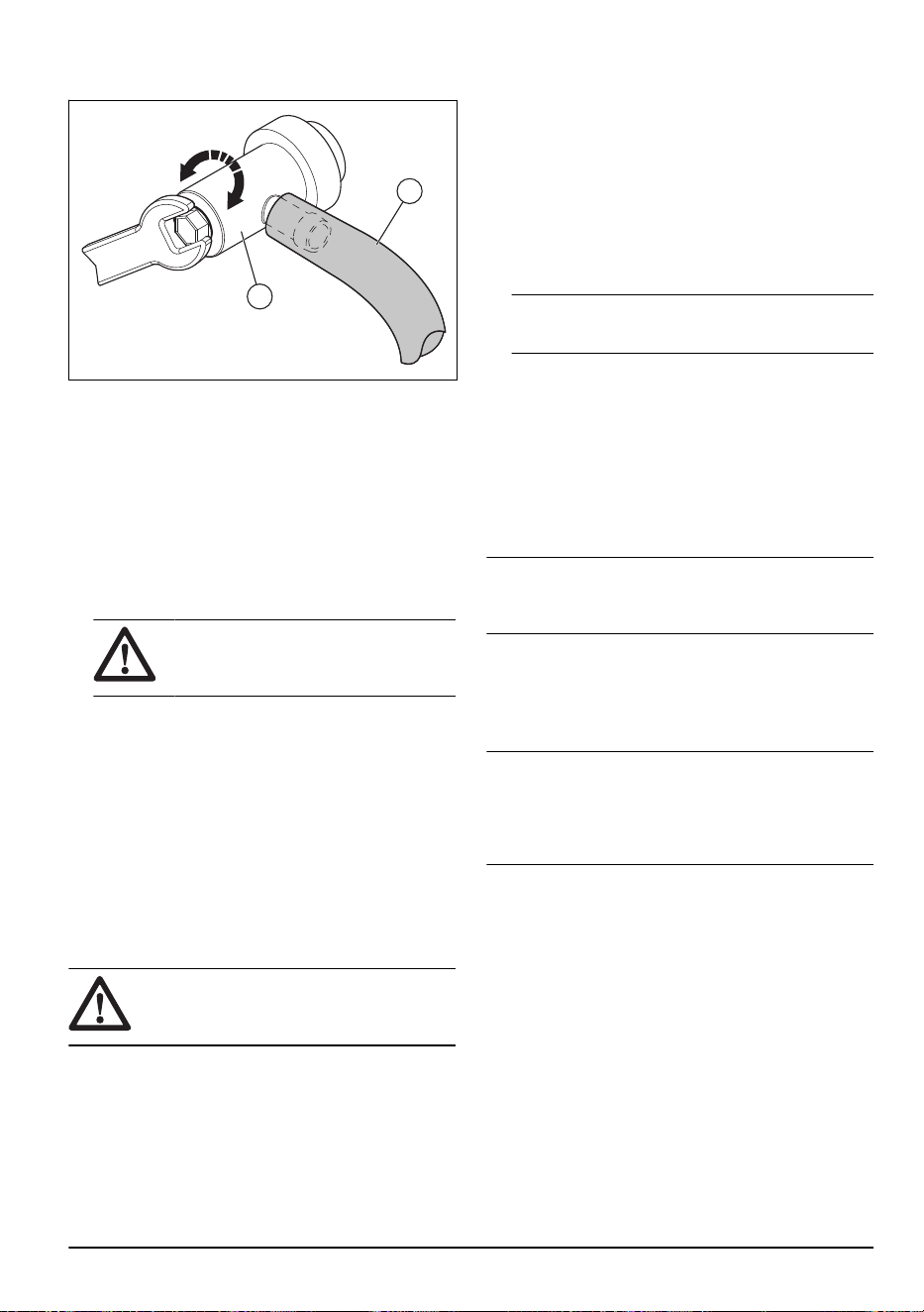
4. Instale el tubo de drenaje de aceite (A) en la válvula
de drenaje de aceite del motor (B).
A
B
5. Coloque un recipiente debajo del motor para reunir
el aceite del motor.
6. Gire la válvula de drenaje de aceite hacia la
izquierda para abrir la válvula de drenaje de aceite.
Utilice una llave de 10mm.
7. Cuando se haya drenado todo el aceite del motor,
gire la válvula de drenaje de aceite hacia la derecha
para cerrarla. Utilice una llave de 10mm.
8. Utilice la llave de 10mm para apretar
cuidadosamente la válvula de drenaje de aceite en
la posición cerrada. No apriete en exceso.
AVISO: No aplique demasiada fuerza
cuando apriete la válvula de drenaje de
aceite.
9. Retire el tubo de drenaje de aceite de la válvula de
drenaje de aceite.
10. Llene el motor con aceite de motor nuevo a través
del tubo de la varilla de nivel. Llene lentamente. No
llene el motor con demasiado aceite de motor. Para
conocer la capacidad aproximada, consulte
Datos
técnicos en la página 82
.
11. Revise el nivel de aceite del motor. Consulte
Para
revisar el nivel de aceite del motor en la página 72
.
12. Instale la cubierta inferior. Consulte
Para instalar la
cubierta inferior en la página 72
.
Para reemplazar el filtro de aceite del motor
ADVERTENCIA:
Use guantes
protectores. Si se derrama aceite del motor
en su cuerpo, limpie con agua y jabón.
1. Drene el aceite del motor del depósito de aceite.
Consulte
Para cambiar el aceite del motor en la
página 72
.
2. Gire el filtro de aceite del motor hacia la izquierda
para retirarlo.
3. Lubrique ligeramente la junta de goma del nuevo
filtro de aceite con aceite de motor nuevo.
4. Para instalar el nuevo filtro de aceite, gírelo en el
sentido de las agujas del reloj hasta que la junta de
goma quede en su posición correctamente y, luego,
apriete media vuelta más.
5. Llene el depósito de aceite con aceite de motor
nuevo. Consulte
Para cambiar el aceite del motor
en la página 72
.
6. Arranque el motor y déjelo funcionar en régimen de
ralentí durante 3minutos.
7. Detenga el motor y asegúrese de que no haya fugas
de aceite en el filtro de aceite.
Tenga en cuenta: Si hay fugas de aceite,
apriete el filtro de aceite nuevamente.
8. Llene el depósito de aceite con un poco más de
aceite para reemplazar el que se absorbió por el
nuevo filtro de aceite.
Para limpiar el filtro de aire
El motor no funcionará de forma satisfactoria con un
filtro de aire sucio. Limpie el filtro de aire con más
frecuencia en condiciones polvorientas.
Para limpiar la pantalla de aire
Tenga en cuenta: La pantalla de aire se debe
mantener libre de suciedad para evitar daños al motor
causados por un sobrecalentamiento.
• Limpie la pantalla de aire con un cepillo de alambre
o con aire comprimido para eliminar la suciedad.
Para realizar mantenimiento en el sistema
refrigerante del motor
Tenga en cuenta:
Una pantalla de césped
bloqueada, las aletas de refrigeración sucias o llenas,
una carcasa de la sopladora retirada, etcétera, pueden
hacer que el motor se caliente demasiado y causar
daños en el motor.
• Asegúrese de que la pantalla de césped, las aletas
de refrigeración y otras superficies externas del
motor estén limpias en todo momento.
• Después de cada intervalo de 100horas de
funcionamiento (con más frecuencia en condiciones
polvorientas y de suciedad extremas), retire la
carcasa de la sopladora y otras piezas del
sistema refrigerante del motor. Limpie las aletas de
enfriamiento y las superficies externas conforme sea
necesario. Asegúrese de que las piezas del sistema
refrigerante del motor se instalen correctamente.
Para revisar el silenciador
• Examine el silenciador con regularidad para
asegurarse de que está instalado correctamente y
que no esté dañado.
2231 - 003 - 22.09.2023
73

Para reemplazar las bujías
El tipo de bujía y el espacio (ajuste de la separación) se
muestran en .
• Reemplace las bujías al comienzo de cada
temporada de corte o después de cada intervalo de
100horas de funcionamiento.
Para reemplazar el filtro de combustible en
línea
Tenga en cuenta: Reemplace el filtro de
combustible en línea cada año como mínimo.
Reemplace el filtro en línea cuando se obstruya y
detenga el flujo de combustible al carburador.
1. Deje que el motor se enfríe.
2. Retire el filtro de combustible en línea (B) y selle las
secciones de línea de combustible con tapones.
3. Coloque el nuevo filtro de combustible en línea en
su posición en el tubo de combustible con la flecha
apuntando hacia el carburador.
4. Asegúrese de que no haya fugas en la tubería de
combustible y que las abrazaderas (A) estén en la
posición correcta.
5. Si se derrama, limpie el producto inmediatamente.
A
B
Para extraer el producto desde la
transmisión
AVISO:
No acople ni desacople la
palanca de rueda libre mientras el motor
esté en marcha.
Para mantener el alto rendimiento, retire el aire en la
transmisión antes de operar el producto por primera
vez.
Si reemplaza la transmisión, retire el aire en la nueva
transmisión antes de operar el producto.
1. Estacione el producto en una superficie horizontal
que esté despejada y abierta.
2. Detenga el motor y acople el freno de
estacionamiento.
3. Coloque el control de la rueda libre en la posición
desacoplada. Consulte
Transporte en la página 81
.
4. Arranque el motor. Una vez que el motor haya
arrancado, mueva el acelerador a la posición lenta
y, luego, desacople el freno de estacionamiento.
5. Realice los pasos que siguen 3 veces.
Tenga en cuenta: Durante este
procedimiento, puede haber movimiento de las
ruedas motrices.
a) Pise el pedal de avance hasta la posición
de avance máxima y manténgalo presionado
durante 5segundos antes de soltarlo.
b) Pise el pedal de marcha atrás hasta la posición
de inversa máxima y manténgalo presionado
durante 5segundos antes de soltarlo.
6. Detenga el motor y acople el freno de
estacionamiento.
7. Coloque el control de la rueda libre en la posición
acoplada. Consulte
Transporte en la página 81
.
8. Siéntese en el asiento y arranque el motor. Una vez
que el motor haya arrancado, mueva lentamente el
acelerador a la posición de aceleración máxima.
9. Desacople el freno de estacionamiento.
10. Opere el producto hacia delante aproximadamente
5pies (1,5m) y luego hacia atrás por 5pies (1,5m).
Realice este procedimiento tresveces.
74
2231 - 003 - 22.09.2023

Solución de problemas
Problema Causa Acción
El motor no arranca. No hay combustible en el depósito
de combustible.
Llene el depósito de combustible.
El acelerador no está en la posición
correcta.
Consulte las instrucciones de arran-
que.
La bujía está dañada. Reemplace la bujía.
El filtro de aire está sucio. Limpie o reemplace el filtro de aire.
El filtro de combustible está obstrui-
do.
Reemplace el filtro de combustible.
Hay agua en el combustible. Quite todo el combustible del depósi-
to de combustible y del carburador.
Llene el depósito de combustible con
combustible nuevo y cambie el filtro
de combustible.
Los cables están sueltos o dañados. Compruebe todos los cables.
Las válvulas del motor no están ajus-
tadas correctamente.
Comuníquese con un taller de servi-
cio autorizado.
El motor está inundado. Espere de 2 a 3minutos antes de in-
tentar arrancar el motor nuevamente.
El combustible en el depósito de
combustible está defectuoso.
Cambie el combustible en el depósito
de combustible.
2231 - 003 - 22.09.2023 75

Problema Causa Acción
El motor de arranque no hace girar el
motor.
La batería tiene muy poca carga. Cargue la batería.
El control del embrague de acopla-
miento está conectado.
Desconecte el control del embrague
de acoplamiento.
El pedal de embrague/freno no está
presionado completamente.
Pise completamente el pedal de em-
brague/freno cuando arranque el mo-
tor.
La conexión de los conectores del
cable con los terminales de la batería
está mal.
Revise las conexiones de la batería.
El fusible principal está dañado. Reemplace el fusible principal.
El bloqueo de encendido está daña-
do.
Comuníquese con un taller de servi-
cio autorizado.
El conector de seguridad del pedal
de embrague/freno está dañado.
Comuníquese con un taller de servi-
cio autorizado.
El motor de arranque o el solenoide
están dañados.
Comuníquese con un taller de servi-
cio autorizado.
El control de presencia del usuario
(OPC) no funciona correctamente.
Compruebe los cables, interruptores
y conexiones. Si no se puede corre-
gir, consulte a un taller de servicio
aprobado. No utilice un producto con
un control de presencia del usuario
que no funcione correctamente.
76 2231 - 003 - 22.09.2023

Problema Causa Acción
El motor no funciona correctamente. La bujía está dañada. Reemplace la bujía.
El carburador no está ajustado co-
rrectamente.
Comuníquese con un taller de servi-
cio autorizado.
El filtro de aire está sucio. Limpie o reemplace el filtro de aire.
La válvula de retención en el tapón
del depósito de combustible está da-
ñada.
Reemplace la tapa del depósito de
combustible.
El depósito de combustible está casi
vacío.
Llene el depósito con combustible.
Hay agua en el combustible. Quite todo el combustible del depósi-
to de combustible y del carburador.
Llene el depósito de combustible con
combustible nuevo y cambie el filtro
de combustible.
El estrangulador está accionado y el
motor está caliente.
Desactive el estrangulador.
La mezcla de combustible o el tipo
de combustible son incorrectos.
Quite todo el combustible del depósi-
to de combustible y del carburador.
Llene el depósito de combustible con
la mezcla o el tipo de combustible
correcto.
El filtro de combustible está obstrui-
do.
Reemplace el filtro de combustible.
La bujía está dañada. Reemplace la bujía.
Hay suciedad en el carburador o la
tubería de combustible.
Limpie el carburador y los tubos de
combustible.
El motor se sobrecalienta. Hay sobrecarga en el motor. Disminuya la carga de trabajo.
La toma de aire o las aletas de re-
frigeración del motor están bloquea-
das.
Limpie la toma de aire y las aletas de
refrigeración del motor.
El ventilador de refrigeración está da-
ñado.
Comuníquese con un taller de servi-
cio autorizado.
El nivel de aceite del motor es dema-
siado bajo.
Revise el nivel de aceite del motor.
Rellene con aceite del motor si es
necesario.
El bloqueo de encendido está daña-
do.
Comuníquese con un taller de servi-
cio autorizado.
La bujía está dañada. Reemplace la bujía.
2231 - 003 - 22.09.2023 77

Problema Causa Acción
Hay una pérdida de potencia. El producto funciona a una velocidad
de avance o retroceso demasiado al-
ta cuando corta césped.
Utilice una velocidad más baja.
El acelerador está en la posición de
estrangulamiento.
Coloque el acelerador en la posición
rápida.
Hay acumulación de césped, hojas o
material no deseado debajo del equi-
po de corte.
Limpie el equipo de corte.
El filtro de aire está sucio. Limpie o reemplace el filtro de aire.
El nivel de aceite del motor es dema-
siado bajo.
Revise el nivel de aceite del motor.
Rellene con aceite del motor si es
necesario.
El aceite del motor está sucio. Cambie el aceite del motor.
La bujía está dañada. Reemplace la bujía.
El filtro de combustible está sucio. Reemplace el filtro de combustible.
El combustible en el depósito de
combustible está defectuoso.
Cambie el combustible en el depósito
de combustible.
Hay agua en el combustible. Quite todo el combustible del depósi-
to de combustible y del carburador.
Llene el depósito de combustible con
combustible nuevo y cambie el filtro
de combustible.
El cable de la bujía está suelto. Conecte y apriete el cable de la bu-
jía.
La toma de aire o las aletas de re-
frigeración del motor están bloquea-
das.
Limpie la toma de aire y las aletas de
refrigeración del motor.
El silenciador está obstruido o daña-
do.
Limpie o reemplace el silenciador.
Hay cables flojos o dañados. Compruebe todos los cables.
Las válvulas del motor no están ajus-
tadas correctamente.
Comuníquese con un taller de servi-
cio autorizado.
Hay vibración en el producto. Las cuchillas están sueltas. Apriete los pernos de las hojas.
Una o varias hojas están dañadas o
se encuentran desequilibradas.
Equilibre las hojas o reemplácelas.
El motor está suelto. Apriete los pernos del motor.
La batería no se carga. El fusible principal está dañado. Reemplace el fusible principal.
La batería está dañada. Cambie la batería.
El cable de carga está desconecta-
do.
Conecte el cable de carga.
La conexión de los conectores del
cable con los terminales de la batería
está mal.
Revise las conexiones de la batería.
78 2231 - 003 - 22.09.2023

Problema Causa Acción
El motor funciona cuando el opera-
dor se sube del asiento y el equipo
de corte está acoplado. El control de presencia del usuario
(OPC) no funciona correctamente.
Compruebe los cables, interruptores
y conexiones. Si no se puede corre-
gir, consulte a un taller de servicio
aprobado. No utilice un producto con
un control de presencia del usuario
que no funcione correctamente.
Las hojas no pueden girar. Hay un bloqueo en el mecanismo del
embrague.
Elimine la obstrucción.
La correa de transmisión del equipo
está desgastada o dañada.
Reemplace la correa de transmisión
del equipo de corte.
Una polea tensora está congelada. Cambie la polea tensora.
Un mandril de hoja está congelado. Reemplace el mandril de la cuchilla.
Descarga de césped dañada. El régimen del motor es demasiado
bajo.
Coloque el acelerador en la posición
rápida.
El producto funciona a una velocidad
de avance o retroceso demasiado al-
ta.
Utilice una velocidad más baja.
El césped está mojado. Deje que el césped se seque antes
de cortarlo.
El equipo de corte no es paralelo. Ajuste el paralelismo del equipo de
corte. Consulte
Para ajustar el para-
lelismo del equipo de corte en la pá-
gina 68
.
La presión de los neumáticos es in-
correcta.
Revise la presión de los neumáticos.
Ajuste la presión de los neumáticos
si es necesario.
Las hojas están desgastadas, daña-
das o sueltas.
Reemplace las hojas o ajuste los
pernos de las hojas.
Acumulación de césped o suciedad
debajo del equipo de corte.
Limpie el equipo de corte.
La correa de transmisión del equipo
está desgastada o dañada.
Reemplace la correa de transmisión
del equipo de corte.
Las hojas están mal instaladas. Instale las cuchillas con el borde afi-
lado hacia abajo.
Se están usando las hojas incorrec-
tas.
Reemplace las hojas con las hojas
correctas que se indican en el ma-
nual de piezas.
Orificios de aire obstruidos en el
equipo de corte por acumulación de
césped y suciedad alrededor de los
mandriles.
Limpie alrededor de los mandriles
para abrir los orificios de ventilación.
2231 - 003 - 22.09.2023 79

Problema Causa Acción
El faro no funciona. Asegúrese de que el interruptor del
faro esté en la posición de apagado.
Coloque el interruptor del faro en la
posición de encendido.
El foco está dañado. Reemplace el foco.
El interruptor de alimentación del fo-
co está dañado.
Reemplace el interruptor de alimen-
tación del faro.
El cable que va al faro no está co-
nectado.
Compruebe los cables y las conexio-
nes.
Hay un cortocircuito en el cable del
faro.
Comuníquese con un taller de servi-
cio autorizado.
El producto se mueve lentamente,
con velocidad irregular o no se mue-
ve.
El producto está en el modo de rue-
da libre.
Tire hacia afuera de la palanca de
control de rueda libre. Consulte
Para
poner el producto en modo de rueda
libre en la página 58
.
El freno de estacionamiento está ac-
cionado.
Desacople el freno de estaciona-
miento.
La correa de transmisión está suelta
o defectuosa.
Reemplace la correa de transmisión.
Hay aire en la transmisión. Extraiga el aire de la transmisión.
Consulte
Para extraer el producto
desde la transmisión en la página 74
.
Hay materiales no deseados en la
placa de dirección (si la placa de di-
rección está instalada).
Limpie la máquina.
Falta la llave cuadrada del eje. Instale la llave cuadrada. Consulte
Para reparar los neumáticos en la
página 63
.
El resultado de corte no es satisfac-
torio.
Las hojas están desafiladas o daña-
das.
Afile las cuchillas o reemplácelas.
El equipo de corte no está paralelo. Ajuste el paralelismo del equipo de
corte. Consulte
Para ajustar el para-
lelismo del equipo de corte en la pá-
gina 68
.
El césped está mojado. Deje que el césped se seque antes
de cortarlo.
El césped es largo. Empiece con una altura de corte ele-
vada y reduzca gradualmente.
La presión de los neumáticos es in-
correcta.
Revise la presión de los neumáticos.
Ajuste la presión de los neumáticos
si es necesario.
El producto funciona a una velocidad
de avance o retroceso demasiado al-
ta.
Utilice una velocidad más baja.
La correa de transmisión del equipo
está desgastada o dañada.
Reemplace la correa de transmisión
del equipo de corte.
El motor petardea cuando se detie-
ne.
El acelerador no se encuentra en la
posición lenta.
Consulte
Para detener el producto en
la página 56
.
80 2231 - 003 - 22.09.2023

Problema Causa Acción
El motor se detiene cuando intenta
retroceder.
El sistema de operación inversa
(ROS) no está activado.
Active el sistema de operación inver-
sa (ROS). Consulte
Para utilizar el
sistema de funcionamiento en rever-
sa (ROS) en la página 58
.
Transporte, almacenamiento y eliminación de residuos
Transporte
Tenga en cuenta: Cierre y fije la cubierta
al producto durante el transporte para evitar daños.
Conecte la cubierta al producto con las herramientas
correctas (cuerda, cable y otros).
Cuando mueva el producto, coloque el control de la
rueda libre en la posición de rueda libre para desacoplar
la transmisión. El control de rueda libre se ubica en la
barra de tracción trasera del producto.
1. Levante el accesorio a la posición más alta con el
control de elevación del acoplamiento.
2. Retire el control de la rueda libre, insértelo en
la ranura y suéltelo para que se mantenga en la
posición desacoplada.
3. No mueva el producto a más de dos (2) mph
(3,2km/h).
4. Para volver a acoplar la transmisión, haga el
procedimiento anterior en el orden inverso.
Seguridad de remolque
• Utilice únicamente equipos de remolque aprobados
por Husqvarna.
• Utilice la barra de remolque para conectar el equipo.
• No remolque equipos más pesados que el peso
máximo permitido.
• Cuando remolque equipos, asegúrese de que no
haya otras personas cerca de la máquina.
• No remolque equipos en pendientes ni en terreno
irregular.
• Opere la máquina a baja velocidad cuando remolque
equipos.
Almacenamiento
Prepare el producto para guardarlo al final de
la temporada, y antes de más de 30 días de
almacenamiento. Si mantiene combustible en el
depósito de combustible durante 30 días o más,
partículas pegajosas pueden obstruir el carburador.
Esto afecta negativamente el funcionamiento del motor.
Para evitar partículas pegajosas durante el
almacenamiento, agregue un estabilizador. Si se utiliza
gasolina de alquilato, no es necesario un estabilizador.
Si se utiliza gasolina estándar, no cambie a gasolina
de alquilato. Esto puede provocar que las piezas de
goma sensibles se endurezcan. Agregue estabilizador
al combustible del depósito o al contenedor usado para
el almacenamiento. Utilice siempre las proporciones de
mezcla indicadas por el fabricante. Haga funcionar el
motor durante un mínimo de 10minutos después de
agregar el estabilizador hasta que fluya al carburador.
ADVERTENCIA: No mantenga el
producto con combustible en el depósito en
interiores o en lugares con mala ventilación.
Existe riesgo de incendio si los vapores
de combustible alcanzan llamas abiertas,
chispas o luces piloto, como calderas,
depósitos de agua caliente y secadoras de
ropa.
ADVERTENCIA: Retire el césped,
las hojas y otros materiales inflamables del
producto para reducir el riesgo de incendio.
Deje que el producto se enfríe antes de
guardarlo.
2231 - 003 - 22.09.2023 81

AVISO: Si retira la batería del
producto, no la mantenga directamente
sobre superficies de hormigón o húmedas.
• Limpie el producto; consulte
Para limpiar el producto
en la página 62
.
• Repare los daños de la pintura para evitar la
corrosión.
• Examine el producto en busca de piezas dañadas
o desgastadas y apriete las tuercas y los tornillos
sueltos.
• Examine las correas y reemplácelas si están
desgastadas o dañadas.
• Si el producto se almacena durante el invierno, retire
y limpie el equipo de corte. Mantenga el equipo de
corte en un entorno limpio y seco.
• Cargue toda la batería.
Tenga en cuenta: Puede ser necesario
cargar la batería nuevamente después de un
período en almacenamiento.
• Desconecte la batería y limpie los terminales y los
conectores. Consulte
Para limpiar la batería y los
terminales en la página 65
.
AVISO: Riesgo de cortocircuito.
Asegúrese de colocar los cables de
batería desconectados en una posición
en la que no puedan tocar la batería ni
los terminales.
• Cambie el aceite del motor y deseche el aceite
residual.
• Vacíe el depósito de combustible. Arranque el motor
y déjelo en marcha hasta que no quede combustible
en el carburador.
Tenga en cuenta: No vacíe el depósito de
combustible ni el carburador si se ha agregado un
estabilizador.
• Extraiga las bujías y ponga aproximadamente una
cucharadita de aceite del motor en cada cilindro.
Gire el eje del motor de forma manual para aplicar el
aceite. Instale las bujías.
• Lubrique todas las boquillas de engrase, juntas y
ejes.
• Mantenga el producto en una zona limpia y seca, y
cúbralo para mayor protección.
AVISO: No coloque una cubierta
sobre el producto cuando el motor o el
escape estén calientes.
• Hay una cubierta de protección para el producto
durante el almacenamiento o el transporte
disponible en su distribuidor.
Eliminación
• Las sustancias químicas pueden ser peligrosas
y no deben tirarse en el suelo. Siempre elimine
los productos químicos utilizados en un centro de
servicio o un lugar adecuado para su eliminación.
• Cuando el producto se desgaste completamente,
envíelo al distribuidor o a un centro de reciclaje
aplicable.
• El aceite, los filtros de aceite, el combustible y
la batería pueden tener efectos negativos en el
ambiente. Obedezca las regulaciones vigentes y
requisitos de reciclaje locales.
• No deseche la batería como un residuo doméstico.
• Envíe la batería a un taller de servicio Husqvarna o
deséchela en un lugar para eliminación de baterías
usadas.
Datos técnicos
TS 348XD
Motor
Marca del motor Kawasaki
Modelo de motor FR730V
Potencia normal del motor, HP / kW
2
24 / 17,9 a 3400 rpm
2
La potencia nominal declarada por el fabricante del motor es la salida de potencia bruta promedio en las RPM
especificadas de un motor típico de producción para el modelo del motor medido utilizando las normas SAE
de potencia bruta del motor. Consulte las especificaciones del motor del fabricante.
82 2231 - 003 - 22.09.2023

TS 348XD
Máx. régimen del motor, rpm 3300±100
Régimen máximo de avance, mph / km/h 5,5 / 8,9
Régimen máximo de retroceso, mph / km/h 2,5 / 4
Combustible, grado de octanos mínimo, sin plomo, eta-
nol al 10% máx., un 15% MTBE máx., AKI/RON
87 / 91
Capacidad del depósito de combustible, galón / l 4 / 15,14
Tipo de aceite por encima de 32°F / 0°C (API: SJ-SN): SAE 10W30
Tipo de aceite por debajo de 32°F / 0°C (API: SJ-SN): SAE5W30
Volumen de aceite con filtro de aceite, oz / l 68 / 2,1
Volumen de aceite sin filtro de aceite, oz / l 61 / 1,8
Sistema de lubricación Presión con filtro de aceite
Sistema refrigerante Refrigerado por aire
Filtro de aire Dual
Alternador, V. amp. a 3600 rpm 12V 15A a 3600rpm
Motor de arranque Arranque eléctrico de 12V
Peso
Peso con tanques vacíos, lb / kg 675 / 306
Equipo de corte
Cantidad de cuchillas 3
Longitud de la hoja, in / cm 16,5 / 41,91
Ancho de corte, in / cm 48 / 122
Altura de corte, in / cm 1,5-3,8 / 3,8-9,7
Neumáticos
Presión de los neumáticos, traseros y delanteros, PSI /
kPa / bar
15 / 103 / 1
Neumáticos delanteros, in 16 x de 6,5 a 8
Neumáticos traseros, neumático para césped, in 23 x de 10,5 a 12
Frenos Freno de estacionamiento mecánico
Sistema eléctrico
Tipo 12 V
Batería 28 A
Bujía BPR4ES
Distancia entre los electrodos, in / mm 0,030 / 0,76
Par de la bujía, lb-ft / Nm 16 / 22
2231 - 003 - 22.09.2023 83

Servicio
Servicio
Realice una comprobación anual en un centro de
servicios autorizado para asegurarse de que el producto
funciona de forma segura y a su máximo potencial
durante la temporada alta. El mejor momento para
hacer mantenimiento o reparaciones a este producto es
en la temporada baja.
Cuando envíe un pedido de piezas de repuesto, dé
información sobre el año de compra, modelo, tipo y
número de serie.
Utilice siempre piezas de repuesto originales.
84 2231 - 003 - 22.09.2023

15 DEGREES MAX.
FOLD ALONG DOTTED LINE
THIS IS A 15 DEGREE SLOPE
ONLY RIDE UP AND DOWN HILL,
NOT ACROSS HILL
SUGGESTED GUIDE FOR SIGHTING SLOPES FOR SAFE OPERATION
WARNING: To avoid serious injury, operate your unit up and down the face of slopes,
never across the face. Do not mow slopes greater than 15 degrees.
Make turns gradually to prevent tipping or loss of control. Exercise extreme caution when
changing direction on slopes. Do not mow near drop-offs, ditches, or embankments.
Keep at least the width of the machine awayfrom these hazards.
Failure to follow these warnings could lead to death or serious injury.
1. Fold this page along dotted line indicated above.
2. Hold page before you so that its left edge is vertically parallel to a tree
trunk or other upright structure.
3. Sight across the fold in the direction of hill slope you want to measure.
4. Compare the angle of the fold with the slope of the hill.
2231 - 003 - 22.09.2023 85

86 2231 - 003 - 22.09.2023

2231 - 003 - 22.09.2023 87

www.husqvarna.com
Original instructions
Instrucciones originales
1143738-49 Rev. 1
2023-09-26