R&S
®
NGA100
Power Supply
User Manual
5601891902
Version 05
(Æ1çC2)

This manual describes the following R&S
®
NGA100 models with firmware version 1.00 and higher:
●
R&S
®
NGA101 One-Channel 35V/6A Power Supply 40 W (5601.8002.02)
●
R&S
®
NGA102 Two-Channel 35V/6A Power Supply 80 W (5601.8002.04)
●
R&S
®
NGA141 One-Channel 100V/2A Power Supply 40 W (5601.8002.03)
●
R&S
®
NGA142 Two-Channel 100V/2A Power Supply 80 W (5601.8002.05)
In addition to the base unit, the following options are described:
●
R&S
®
NGA-K102 Option Wireless LAN (5601.8419.03)
●
R&S
®
NGA-K103 Option Digital I/O (5601.8425.03)
© 2021 Rohde & Schwarz GmbH & Co. KG
Mühldorfstr. 15, 81671 München, Germany
Phone: +49 89 41 29 - 0
Email:
Internet: www.rohde-schwarz.com
Subject to change – data without tolerance limits is not binding.
R&S
®
is a registered trademark of Rohde & Schwarz GmbH & Co. KG.
Trade names are trademarks of the owners.
5601.8919.02 | Version 05 | R&S
®
NGA100
Throughout this manual, products from Rohde & Schwarz are indicated without the
®
symbol, e.g. R&S
®
NGA is indicated as
R&S NGA100.
1171.1307.42 - 05
1
Safety Instructions
Instrucciones de seguridad
Sicherheitshinweise
Consignes de sécurité
Risk of injury and instrument damage
The instrument must be used in an appropriate manner to prevent
electric shock, fire,
personal injury or instrument damage.
●
Do not open the instrument casing.
●
Read and observe the "Basic Safety Instructions" delivered as
printed brochure with the instrument.
●
Read and observe the safety instructions in the following sections.
Note that the data sheet may specify additional operating conditions.
●
Keep the "Basic Safety Instructions" and the product documentation
in a safe place and pass them on to the subsequent users.
Riesgo de lesiones y daños en el instrumento
El instrumento se debe usar de manera adecuada para p
revenir
descargas eléctricas, incendios, lesiones o daños materiales.
●
No abrir la carcasa del instrumento.
●
Lea y cumpla las "Instrucciones de seguridad elementales"
suministradas con el instrumento como folleto impreso.
●
Lea y cumpla las instrucciones de seguridad incluidas en las
siguientes secciones. Se debe tener en cuenta que las
especificaciones técnicas pueden contener condiciones adicionales
para su uso.
●
Guarde bien las instrucciones de seguridad elementales, así como
la documentación del producto, y entréguelas a usuarios
posteriores.
1171.1307.42 - 05
2
Gefahr von Verletzungen und Schäden am Gerät
Betreiben Sie das Gerät immer ordnungsgemäß, um elektrischen
Schlag, Brand, Verletzungen von Personen oder Geräteschäden zu
verhindern.
●
Öffnen Sie das Gerätegehäuse nicht.
●
Lesen und beachten Sie die "Grundlegenden Sicherheitshinweise",
die als gedruckte Broschüre dem Gerät beiliegen.
●
Lesen und beachten Sie die Sicherheitshinweise in den folgenden
Abschnitten; möglicherweise enthält das Datenblatt weitere
Hinweise zu speziellen Betriebsbedingungen.
●
Bewahren Sie die "Grundlegenden Sicherheitshinweise" und die
Produktdokumentation gut auf und geben Sie diese an weitere
Benutzer des Produkts weiter.
Risque de blessures et d'endommagement de l'appareil
L'ap
pareil doit être utilisé conformément aux prescriptions afin d'éviter
les électrocutions, incendies, dommages corporels et matériels.
●
N'ouvrez pas le boîtier de l'appareil.
●
Lisez et respectez les "consignes de sécurité fondamentales"
fournies avec l’appareil sous forme de brochure imprimée.
●
Lisez et respectez les instructions de sécurité dans les sections
suivantes. Il ne faut pas oublier que la fiche technique peut indiquer
des conditions d’exploitation supplémentaires.
●
Gardez les consignes de sécurité fondamentales et la
documentation produit dans un lieu sûr et transmettez ces
documents aux autres utilisateurs.

이 기기는 업무용(A급) 전자파
적합기기로서 판매자 또는
사용자는 이 점을 주의하시기
바라며, 가정외의 지역에서
사용하는 것을 목적으로 합니다.
1171.0200.78-01

Contents
R&S
®
NGA100
3User Manual 5601.8919.02 ─ 05
Contents
1 Documentation Overview......................................................................7
1.1 Manuals..........................................................................................................................7
1.2 Data Sheet......................................................................................................................7
1.3 Calibration Certificate...................................................................................................7
1.4 Release Notes, Open Source Acknowledgment........................................................ 8
2 Welcome to R&S NGA100..................................................................... 9
3 Important Notes....................................................................................10
3.1 Symbols....................................................................................................................... 10
3.2 Ambient Conditions.................................................................................................... 10
3.3 Measurement Categories............................................................................................11
3.4 Mains Voltage...............................................................................................................11
3.5 Limits............................................................................................................................12
4 Getting Started..................................................................................... 13
4.1 Putting into Operation................................................................................................ 13
4.1.1 Safety............................................................................................................................ 14
4.1.2 Intended Operation....................................................................................................... 15
4.1.3 Unpacking and Checking the Instrument...................................................................... 17
4.1.4 Setting Up the Instrument............................................................................................. 17
4.1.4.1 Bench Operation........................................................................................................... 18
4.1.4.2 Rack Mounting.............................................................................................................. 18
4.2 Instrument Tour...........................................................................................................19
4.2.1 Overview of Controls.....................................................................................................19
4.2.1.1 Front Panel....................................................................................................................19
4.2.1.2 Rear Panel.................................................................................................................... 21
4.2.1.3 Bottom Panel.................................................................................................................23
4.2.2 Switching On the Instrument......................................................................................... 23
4.3 Trying Out the Instrument.......................................................................................... 24
4.3.1 Selecting the Channels................................................................................................. 24
4.3.2 Setting the Output Voltage and Current Limit................................................................25
4.3.3 Activating the Channels Output.....................................................................................25

Contents
R&S
®
NGA100
4User Manual 5601.8919.02 ─ 05
4.3.4 Storing/Recalling of Instrument Settings....................................................................... 25
4.4 Maintenance and Support.......................................................................................... 26
4.4.1 Maintenance..................................................................................................................26
4.4.2 Contacting Customer Support.......................................................................................27
5 Operating Basics..................................................................................28
5.1 Display Overview........................................................................................................ 28
5.1.1 Status Bar Information.................................................................................................. 28
5.1.2 Channel Display Area................................................................................................... 29
5.2 Front Panel Keys.........................................................................................................30
5.2.1 Function Keys............................................................................................................... 31
5.2.1.1 Output and Channel Controls........................................................................................31
5.2.1.2 Navigation Keys............................................................................................................ 32
5.2.1.3 Instrument Functions.....................................................................................................32
5.2.1.4 Memory Functions.........................................................................................................32
5.2.2 Navigation Controls.......................................................................................................33
5.2.2.1 Rotary Knob.................................................................................................................. 33
5.2.2.2 Arrow Keys....................................................................................................................33
5.2.2.3 Live-Mode..................................................................................................................... 34
5.2.3 Menu Key...................................................................................................................... 34
5.3 On-screen Keyboard...................................................................................................36
5.4 Power Derating............................................................................................................37
5.5 Operation Modes.........................................................................................................38
6 Instrument Functions.......................................................................... 40
6.1 Setting the Channels Voltage and Current............................................................... 40
6.2 Activating the Channel Output.................................................................................. 41
6.3 Current Range............................................................................................................. 42
6.4 Remote Sense Function............................................................................................. 43
6.5 Channel Fusion........................................................................................................... 44
6.6 Activating Fuse........................................................................................................... 46
6.6.1 Fuse Delay, Fuse Linking..............................................................................................47
6.7 Tracking Function....................................................................................................... 48
6.8 Protection.................................................................................................................... 48
6.9 Digital Trigger I/O........................................................................................................ 50

Contents
R&S
®
NGA100
5User Manual 5601.8919.02 ─ 05
6.10 Data Logging............................................................................................................... 53
6.11 Advanced Functions...................................................................................................54
6.11.1 EasyArb.........................................................................................................................54
6.11.2 EasyRamp.....................................................................................................................56
6.12 Store and Recall.......................................................................................................... 57
6.13 Interfaces and Protocols............................................................................................ 59
6.13.1 Network Connection......................................................................................................59
6.13.1.1 LAN Connection............................................................................................................ 60
6.13.1.2 Wireless LAN Connection............................................................................................. 62
6.13.2 USB Connection............................................................................................................63
6.13.2.1 USB VCP...................................................................................................................... 64
6.13.2.2 USB TMC...................................................................................................................... 65
6.13.3 SCPI..............................................................................................................................66
6.13.4 VISA.............................................................................................................................. 66
6.13.5 Setting Up Remote Control Connection........................................................................ 67
6.14 General Instrument Settings...................................................................................... 68
6.14.1 Instrument Information.................................................................................................. 68
6.14.2 General Instrument Settings......................................................................................... 69
6.14.3 Managing Options......................................................................................................... 69
6.14.4 Reset Instrument...........................................................................................................70
6.14.5 System Test...................................................................................................................72
6.14.6 Updating the Firmware..................................................................................................72
6.14.7 Help...............................................................................................................................74
6.14.8 Date Time......................................................................................................................74
7 Remote Control Commands................................................................76
7.1 Common Commands.................................................................................................. 76
7.2 System Commands.....................................................................................................78
7.3 Configuration Commands.......................................................................................... 81
7.3.1 Channel Selecting......................................................................................................... 81
7.3.2 Remote Sense Setting.................................................................................................. 82
7.3.3 Voltage Setting.............................................................................................................. 83
7.3.4 Current Setting.............................................................................................................. 84
7.3.5 Combined Setting of Voltage and Current Setting........................................................ 85

Contents
R&S
®
NGA100
6User Manual 5601.8919.02 ─ 05
7.3.6 Output Setting............................................................................................................... 86
7.3.7 Fuse Setting.................................................................................................................. 89
7.3.8 OVP Setting.................................................................................................................. 93
7.3.9 OPP Setting.................................................................................................................. 96
7.4 Measurement Commands.......................................................................................... 99
7.5 Advanced Operating Commands.............................................................................. 99
7.5.1 Arbitrary Commands................................................................................................... 100
7.5.2 EasyRamp Commands............................................................................................... 102
7.5.3 DIO Commands.......................................................................................................... 102
7.6 Data and File Management Commands.................................................................. 107
7.7 Firmware Update....................................................................................................... 108
8 Applications........................................................................................110
8.1 Parallel and Series Mode.......................................................................................... 110
8.1.1 Series Mode................................................................................................................ 110
8.1.2 Parallel Mode...............................................................................................................111
Annex.................................................................................................. 113
A Additional Basics on Remote Control..............................................113
A.1 Messages and Command Structure........................................................................ 113
A.1.1 Messages.................................................................................................................... 113
A.1.2 SCPI Command Structure...........................................................................................114
A.2 Command Sequence and Synchronization............................................................ 117
A.2.1 Preventing Overlapping Execution.............................................................................. 118
List of commands...............................................................................119
Index....................................................................................................121

Documentation Overview
R&S
®
NGA100
7User Manual 5601.8919.02 ─ 05
1 Documentation Overview
This section provides an overview of the R&S NGA100 user documentation.
1.1 Manuals
You find the documents on the R&S NGA100 product page at:
www.rohde-schwarz.com/manual/nga100
Getting Started
Introduces the R&S NGA100 power supply series and describes how to set up and
start working with the instrument. The printed document is delivered with the instru-
ment.
User manual
Contains the description of all instrument modes and functions. It also provides an
introduction to remote control, a complete description of the remote control commands
with programming examples, and information on maintenance and instrument interfa-
ces. Includes the contents of the getting started manual.
The online version of the user manual provides the complete contents for immediate
display on the internet.
Basic safety instructions
Contains safety instructions, operating conditions and further important information.
The printed document is delivered with the instrument.
Instrument security procedures manual
Deals with security issues when working with the R&S NGA100 in secure areas.
1.2 Data Sheet
The datasheet contains the technical specifications of the R&S NGA100 power supply
series. It also lists all options with their order numbers and accessories.
See
www.rohde-schwarz.com/brochure-datasheet/nga100
1.3 Calibration Certificate
The document is available on https://gloris.rohde-schwarz.com/calcert. You need the
device ID of your instrument, which you can find on a label on the rear panel.
Calibration Certificate

Documentation Overview
R&S
®
NGA100
8User Manual 5601.8919.02 ─ 05
1.4 Release Notes, Open Source Acknowledgment
The release notes list new features, improvements and known issues of the current
firmware version, and describe the firmware installation. The open source acknowledg-
ment document provides verbatim license texts of the used open source software. It
can also be downloaded from the instrument.
See
www.rohde-schwarz.com/firmware/nga100.
Release Notes, Open Source Acknowledgment

Welcome to R&S NGA100
R&S
®
NGA100
9User Manual 5601.8919.02 ─ 05
2 Welcome to R&S NGA100
The one-channel or two-channel power supply series are based on a classical trans-
former concept with high efficiency electronic pre-regulators and secondary linear reg-
ulators. This concept allows the instrument to achieve the high output power within a
minimum space, high efficiency and lowest residual ripple.
The R&S NGA100 power supply series feature galvanically isolated, floating overload
and short-circuit proof outputs with adjustable power ratings. The outputs can be con-
nected in series or in parallel, thus making high currents and voltages available.
Multi-purpose protection functions are available for each channel which you can set
separately, such as overcurrent protection (FUSE), overvoltage protection (OVP), over-
power protection (OPP) and overtemperature protection (OTP). If such a limit is
reached, the affected output channel is automatically turned off and an indicator mes-
sage (FUSE, OVP, OPP or OTP) is displayed. The overcurrent protection can be linked
to other channel (FuseLink function). In this case, all linked channels are turned off
when the set channel reaches its limit.
The EasyArb function allows channel 1 (Ch 1) to have freely definable voltage and cur-
rent sequences with a timeframe as short as 10 ms. It allows you to vary the voltage or
current limit during a test sequence, for example to simulate different charging condi-
tions of a battery. With EasyRamp function, the R&S NGA100 provides the operating
condition to simulate the continuous rise of the supply voltage within a defined time-
frame of 10 ms to 10 s.
Four data lines of the digital I/O interface are mutually independent and can be used as
trigger input or trigger output separately. Various trigger conditions (e.g. fuse tripped,
voltage, current, indicator messages) can be used to turn off, on or invert the output
state when the trigger condition is met.
All R&S NGA100 power supply series are equipped with a color LCD display (320 x
240 pixels resolution). The R&S NGA100 comes with a USB interface, LAN and
optional wireless LAN (WLAN) interface.
For models with WLAN, network connection can also be established wirelessly.
This user manual contains a description of the functionalities that the instrument pro-
vides. The latest version is available for download at the product homepage (
http://
www.rohde-schwarz.com/product/nga100
).
Important Notes
R&S
®
NGA100
10User Manual 5601.8919.02 ─ 05
3 Important Notes
3.1 Symbols
Caution, general danger zone
Ground
PE terminal
ON (supply voltage)
OFF (supply voltage)
Ground terminal
3.2 Ambient Conditions
The allowed operating temperature ranges from +5 °C to +40 °C (pollution category 2).
The maximum relative humidity (without condensation) is at 80 %.
During storage and transport, the temperature must be between -20 °C and +70 °C. In
case of condensation during transportation or storage, the instrument requires approxi-
mately two hours to dry and reach the appropriate temperature prior to operation. The
instrument is designed for use in a clean and dry indoor environment. Do not operate
with high dust and humidity levels, if danger of explosion exists or with aggressive
chemical agents.
Any operating position may be used; however adequate air circulation must be main-
tained. For continuous operation, a horizontal or inclined position (integrated stand) is
preferable.
Specifications with tolerance data apply after a warm-up period of at least 30 minutes
at a temperature of 23 °C (tolerance -3 °C / + 7 °C).
The heat produced inside the instrument is guided to the exterior via temperature-con-
trolled fan. Each channel has multiple temperature sensors which check the heat gen-
eration in the instrument and control the fan speed.
It is necessary to ensure that there is sufficient space around the instrument sides for
heat exchange. If the temperature inside the instrument increases more than the
Ambient Conditions

Important Notes
R&S
®
NGA100
11User Manual 5601.8919.02 ─ 05
allowed limit, overtemperature protection is triggered and the affected outputs are
switched off automatically.
Air circulation
Do not obstruct the ventilation holes!
3.3 Measurement Categories
This instrument is designed for supplying power-on circuits that are only indirectly con-
nected to the low voltage mains or not connected at all. The instrument is not intended
for measurements within the measurement categories II, III or IV; the maximum poten-
tial against earth generated by the user must not exceed 250 V peak in this application.
The following information refers solely to user safety. Other aspects, such as the maxi-
mum voltage, are described in the technical data and must also be observed.
The measurement categories refer to transients that are superimposed on the mains
voltage. Transients are short, very fast (steep) current and voltage variations which
may occur periodically and non-periodically. The level of potential transients increases
as the distance to the source of the low voltage installation decreases.
●
Measurement CAT IV: Measurements at the source of the low voltage installations
(e.g. meters)
●
Measurement CAT III: Measurements in building installations (e.g. power distribu-
tion installations, power switches, firmly installed sockets, firmly installed engines
etc.)
●
Measurement CAT II: Measurements on circuits electronically directly connected to
the mains (e.g. household appliances, power tools, etc.)
●
0 (instruments without measured measurement category): Other circuits that are
not connected directly to the mains
3.4 Mains Voltage
The instrument uses 50 Hz / 60 Hz mains voltages ranging from 100 VAC, 115 VAC or
230 VAC (tolerance ± 10 %). Mains voltage must be set correctly by moving the selec-
tor according to the voltage selector located at the bottom panel. The input line fuse is
accessible externally. Power socket and fuse holder form a single unit.
You need to first disconnect the power cord from the connector before you can safely
replace the fuse (as long as the fuse holder is undamaged). Next, the fuse holder must
be pried out using a screwdriver. The starting point is a slot next to the contacts. The
fuse can then be forced out of its mounting and must be replaced with an identical fuse
(see information about the fuse type on the rear panel). The fuse holder is inserted
against the spring pressure until it locks into place. The use of mended fuses or short
Mains Voltage
Important Notes
R&S
®
NGA100
12User Manual 5601.8919.02 ─ 05
circuiting the fuse holder is prohibited. Resulting damages are not covered by the war-
ranty.
Safe operation
If the instrument is not in use, it must be switched off at the mains switch for safety rea-
sons.
3.5 Limits
The R&S NGA100 is equipped with a protective overload feature. The protective over-
load feature prevents damage to the instrument and is intended to protect against a
possible electrical shock. The maximum values for the instrument must not be excee-
ded. The protection limits are listed on the front panel of the R&S NGA100 to ensure
the safe operation of the instrument.
These protection limits must be adhered to:
Specification Limits
Maximum output voltage 35 V module: 35.00 VDC
100 V module: 100.00 VDC
Maximum output current 35 V module: 6.0
100 V module: 2.0
Maximum voltage against earth 250 VDC
Maximum reverse voltage 35 V module: 36.00 VDC
100 V module: 102.00 VDC
Maximum inverse voltage 0.4 VDC
Maximum permitted current in case of inverse volt-
age
35 V module: 6.00 A
100 V module: 2.00 A
Power supply 100 VAC, 115 VAC or 230 VAC (tolerance ± 10 %)
Frequency 50 Hz / 60 Hz
Maximum power output 40 W (R&S NGA101, R&S NGA141)
80 W (R&S NGA102, R&S NGA142)
Limits
Getting Started
R&S
®
NGA100
13User Manual 5601.8919.02 ─ 05
4 Getting Started
4.1 Putting into Operation
This chapter describes the steps to set up the R&S NGA100 for the first time.
Risk of injury and instrument damage
The instrument must be used in an appropriate manner to prevent electric shock, fire,
personal injury, or damage.
●
Do not open the instrument casing
●
Read and observe the "Basic Safety Instructions" delivered as a printed brochure
with the instrument. Note that the basic safety instructions also contain information
on operating conditions that prevent damage to the instrument
In addition, read and observe the safety instructions in the following sections. Notice
that the data sheet may specify additional operating conditions.
Risk of instrument damage during operation
An unsuitable operating site or test setup can cause damage to the instrument and the
connected devices. Ensure the following operating conditions before you switch on the
instrument:
●
The instrument is dry and shows no sign of condensation
●
The instrument is positioned as described in
Chapter 4.1.4.1, "Bench Operation",
on page 18
●
The ambient temperature does not exceed the range specified in the data sheet
●
Voltage levels at the input connectors are all within the specified ranges
●
Voltage outputs are correctly connected and not overloaded
Risk of radio interference
This is a class A product. In a domestic environment, this product may cause radio
interference in which case the user may be required to take adequate measures.
Putting into Operation
Getting Started
R&S
®
NGA100
14User Manual 5601.8919.02 ─ 05
EMI impact on measurement results
Electromagnetic interference (EMI) may affect the measurement results.
To suppress the generated EMI:
●
Use suitable shielded cables of high quality, for example, LAN cables
●
Note the EMC classification in the data sheet
●
Safety......................................................................................................................14
●
Intended Operation................................................................................................. 15
●
Unpacking and Checking the Instrument................................................................ 17
●
Setting Up the Instrument....................................................................................... 17
4.1.1 Safety
Recommendations on secure operation
The R&S NGA100 is designed to operate at local workplaces or in secured networks
(LAN). It should not be accessible from the internet, because of a potential security
risk, e.g. attackers could misuse or damage your device.
Please always install the latest firmware.
It is highly recommended that you work closely with your IT department or system
administrator to ensure compliance with your company policies when connecting devi-
ces to your company's network.
This instrument was built in compliance with DIN EN 61010-1 (VDE 0411 part 1),
safety regulations for electrical instruments, control units and Iaboratory equipment. It
has been tested and shipped from the plant in safe condition. It is also in compliance
with the regulations of the European standard EN 61010-1 and the international stan-
dard IEC 61010-1.
To maintain this condition and ensure safe operation, you must observe all instructions
and warnings given in this user manual. Casing, chassis and all measuring ports are
connected to a protective earth conductor. The instrument is designed in compliance
with the regulations of protection class I.
For safety reasons, the instrument may only be operated with authorized safety sock-
ets. The power cord must be plugged in before signal circuits may be connected.
Never use the product if the power cable is damaged. Check regularly that the power
cables are in perfect condition. Choose suitable protective measures and installation
types to ensure that the power cord cannot be damaged and that no harm is caused by
tripping hazards or from electric shock, for instance.
Putting into Operation
Getting Started
R&S
®
NGA100
15User Manual 5601.8919.02 ─ 05
Risk of electric shock
It is prohibited to disconnect the earthed protective connection inside or outside of the
instrument!
If it is assumed that a safe operation is no longer possible, the instrument must be shut
down and secured against any unintended operation.
Safe operation can no longer be assumed as follows:
●
Instrument shows visible damage
●
Instrument includes loose parts
●
Instrument no longer functions properly
– After an extended period of storage under unfavorable conditions (e.g. out-
doors or in damp rooms)
– After rough handling during transport (e.g. packaging that does not meet the
minimum requirements by post office, railway or forwarding agency)
Exceeding the low voltage protection
Use insulated wires and not bare wires for the terminal connection.
For the series connection of all output voltages of the 35 V variant, it is possible to
exceed the low voltage protection of 42 V. Please note that in this case any contact
with live components is life-threatening. It is assumed that only qualified and trained
personnel service the power supplies and the connected loads.
Before switching on the product, it must be ensured that the nominal voltage setting on
the product matches the nominal voltage of the AC supply network. If it is necessary to
set a different voltage, the power fuse of the product must be changed accordingly.
4.1.2 Intended Operation
The instrument is intended only for use by personnel familiar with the potential risks of
measuring electrical quantities.
For safety reasons, the instrument may only be connected to properly installed safety
socket outlets. Separating the ground is prohibited.
The power plug must be inserted before signal circuits may be connected.
Use only the power cord included in the delivery package. See
"Delivery package"
on page 17.
Before each measurement, measuring cables must be inspected for damage and
replaced if necessary. Damaged or worn components can damage the instrument or
cause injury.
Putting into Operation
Getting Started
R&S
®
NGA100
16User Manual 5601.8919.02 ─ 05
The product may be operated only under the operating conditions and in the positions
specified by the manufacturer, without the product's ventilation being obstructed. If the
manufacturer’s specifications are not observed, this can result in electric shock, fire
and/or serious personal injury, and in some cases, death.
Provide adequate airflow
Do not block the air intake at the front and side of the instrument or the exhaust at the
rear. Install the instrument on a location that allows sufficient space for air circulation at
the air intake and exhaust. Recommended spacing to non-heat producing surface is at
least 2.5 inches (63.5 mm) from the ventilation holes.
Applicable local or national safety regulations and rules for the prevention of accidents
must be observed in all work performed.
The instrument is designed for use in the following sectors: Industrial, residential, busi-
ness and commercial areas and small businesses.
The instrument is designed for indoor use only. Before each measurement, you need
to verify at a known source if the instrument functions properly.
To disconnect from the mains, the low-heat device socket on the back panel has to be
unplugged.
See
Table 4-1 for the general data on the instrument specification. For more informa-
tion, see the instrument product brochure.
Table 4-1: General data on instrument specification
Mains nominal voltage AC 100 V / 115 V / 230 V (±10 %) 50 Hz / 60
Hz
Power consumption Maximum input power 230 W
Mains fuses
(fuse size: 5 mm x 20 mm)
100 V / 115 V AC IEC 60127 T5.0H250V
230 V AC IEC 60127 T2.5H250V
Temperature Operating temperature range 5 °C to + 40 °C
Storage temperature range - 20 °C to + 70 °C
Humidity Non-condensing 5 % to 80 %
Display
3.5 " (QVGA)
Rack mount capability
R&S HZN96 rack adapter 2U (P/N:
3638.7813.02)
Dimensions W x H x D 222 mm x 96 mm x 446 mm
(8.74 in x 3.78 in x 17.56 in)
Weight R&S NGA101, R&S NGA141 6.6 kg (14.55 lb), 6.9 kg (15.21 lb)
R&S NGA102, R&S NGA142 7.0 kg (15.43 lb), 7.3 kg (16.09 lb)
Putting into Operation
Getting Started
R&S
®
NGA100
17User Manual 5601.8919.02 ─ 05
4.1.3 Unpacking and Checking the Instrument
Check the equipment for completeness using the delivery note and package contents
list for the various items. Check the instrument for any damage and loose parts. If there
is any damage, immediately contact the carrier who delivered the instrument.
Packing material
Retain the original packing material. If the instrument needs to be transported or ship-
ped at a later date, you can use the material to protect the control elements and con-
nectors.
Risk of damage during transportation and shipment
Insufficient protection against mechanical and electrostatic effects during transportation
and shipment can damage the instrument.
●
Always ensure that sufficient mechanical and electrostatic protections are provided
●
When shipping an instrument, the original packaging should be used. If you do not
have the original packaging, use sufficient padding to prevent the instrument from
moving around inside the box. Pack the instrument in antistatic wrap to protect it
from electrostatic charging
●
Secure the instrument to prevent any movement and other mechanical effects dur-
ing transportation
Delivery package
The package contents contain the following items:
●
R&S NGA100 power supply preloaded with two 230 V fuses
●
Four power cables
●
Two 115 V fuses (replace the preloaded fuses with these fuses depending on the
mains voltage, see
Chapter 4.2.2, "Switching On the Instrument", on page 23 for
more information)
●
One 5-pin plug for digital I/O port connection
●
One 8-pin terminal block plug for output connection
●
One Getting Started manual
●
One document folder containing Basic Safety instructions guide, KC and CE certifi-
cate
4.1.4 Setting Up the Instrument
The R&S NGA100 is designed for benchtop and rackmount.
Putting into Operation
Getting Started
R&S
®
NGA100
18User Manual 5601.8919.02 ─ 05
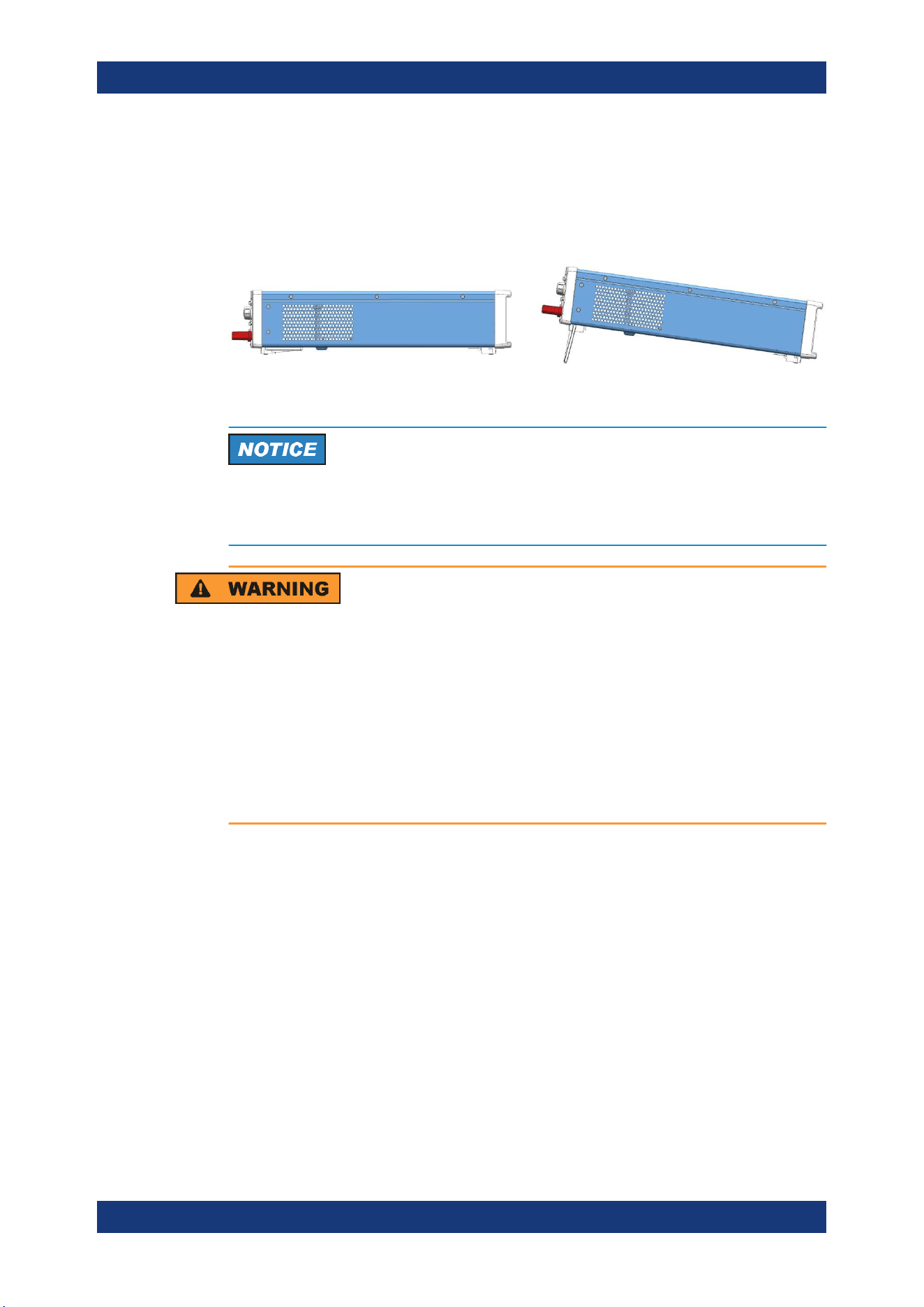
4.1.4.1 Bench Operation
On a benchtop, the R&S NGA100 can either lie flat or stand on its feet. As shown in
Figure 4-1, feet on the bottom can be folded out to set the instrument in an inclined
position.
Figure 4-1: Operating positions
Positioning of instrument
The instrument must be positioned in a manner that allows the user to disconnect the
unit from the mains at any time and without restrictions.
Risk of injury if feet are folded out
The feet can fold in if they are not folded out completely or if the instrument is shifted.
Collapsing feet can cause injury or damage the instrument.
●
Fold the feet completely in or out to ensure stability of the instrument. Never shift
the instrument when the feet are folded out.
●
When the feet are folded out, do not work under the instrument or place anything
underneath.
●
The feet can break if they are overloaded. The overall load on the folded-out feet
must not exceed 250 N.
4.1.4.2 Rack Mounting
The instrument can be installed in a 19" rack using the rack adapter R&S HZN96 (P/N
3638.7813.02). Proceed according to the installation instructions supplied with the rack
adapter.
Putting into Operation
Getting Started
R&S
®
NGA100
19User Manual 5601.8919.02 ─ 05
Ambient temperature
Operate R&S NGA100 power supply in an area where the ambient temperature is
within +5 °C to +40 °C. The R&S NGA100 power supply is fan-cooled and must be
installed with sufficient space along the sides to allow proper air circulation. Ensure
that fan openings are unobstructed and airflow vents are unimpeded.
Operating the instrument with insufficient airflow or outside the allowable ambient tem-
perature can disrupt the operation and even cause damage.
4.2 Instrument Tour
This chapter provides an overview of all the controls available in the R&S NGA100
models and steps to switch on the instrument for the first time.
4.2.1 Overview of Controls
4.2.1.1 Front Panel
The front panel of the R&S NGA100 is as shown in Figure 4-2. The function keys and
navigation controls are located at the right side of the display. The various connectors
are located below the display and function keys.
The following power supply models are available:
Table 4-2: Power supply models
Models Number of output channels
NGA101 (0 V - 35 V/6 A), NGA141 (0 V - 100 V/2 A) 1 (maximum 40 W)
NGA102 (0 V - 35 V/6 A), NGA142 (0 V - 100 V/2 A) 2 (maximum 80 W)
Instrument Tour
Getting Started
R&S
®
NGA100
20User Manual 5601.8919.02 ─ 05
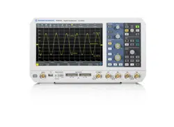
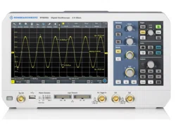
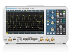
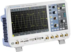
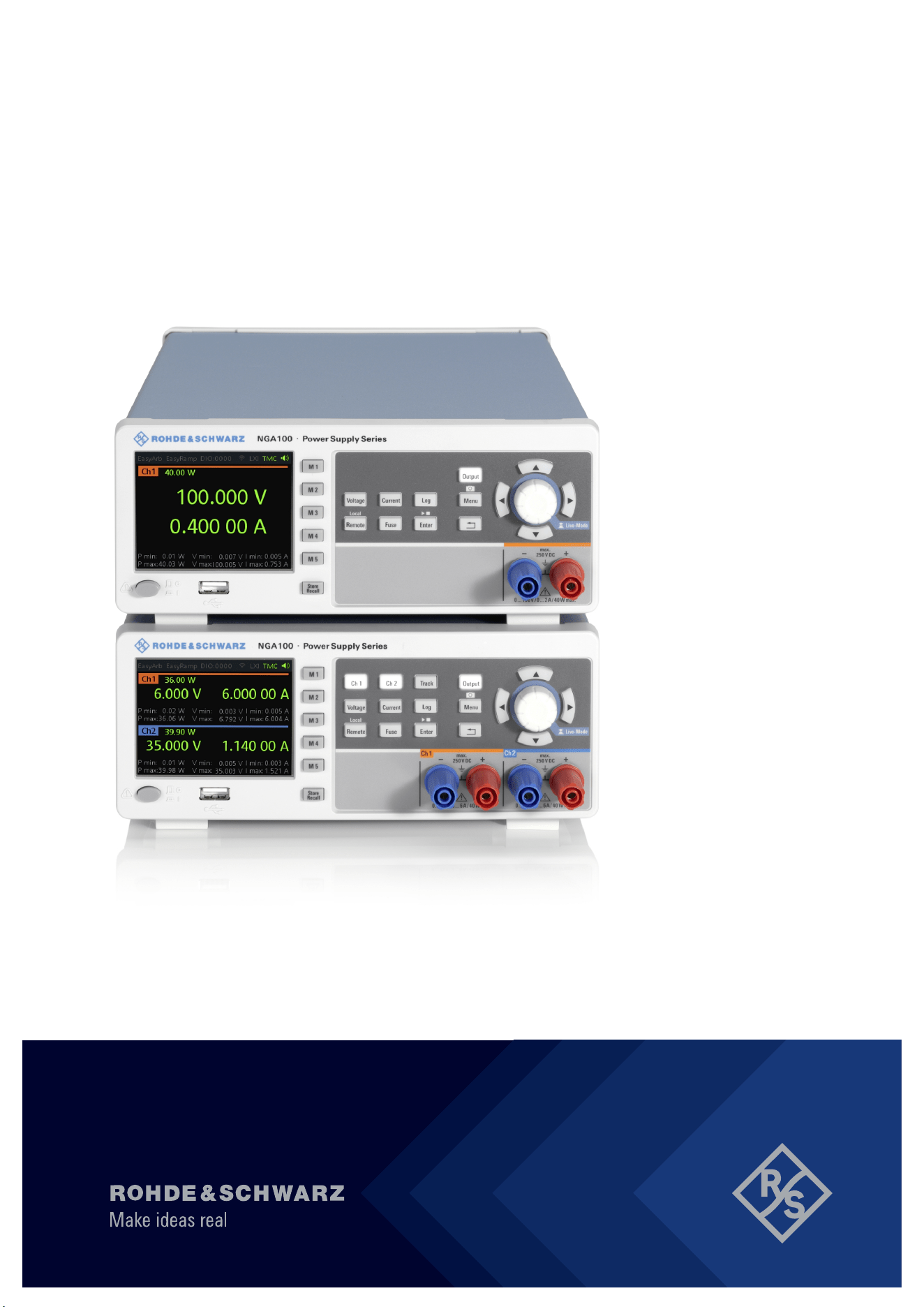
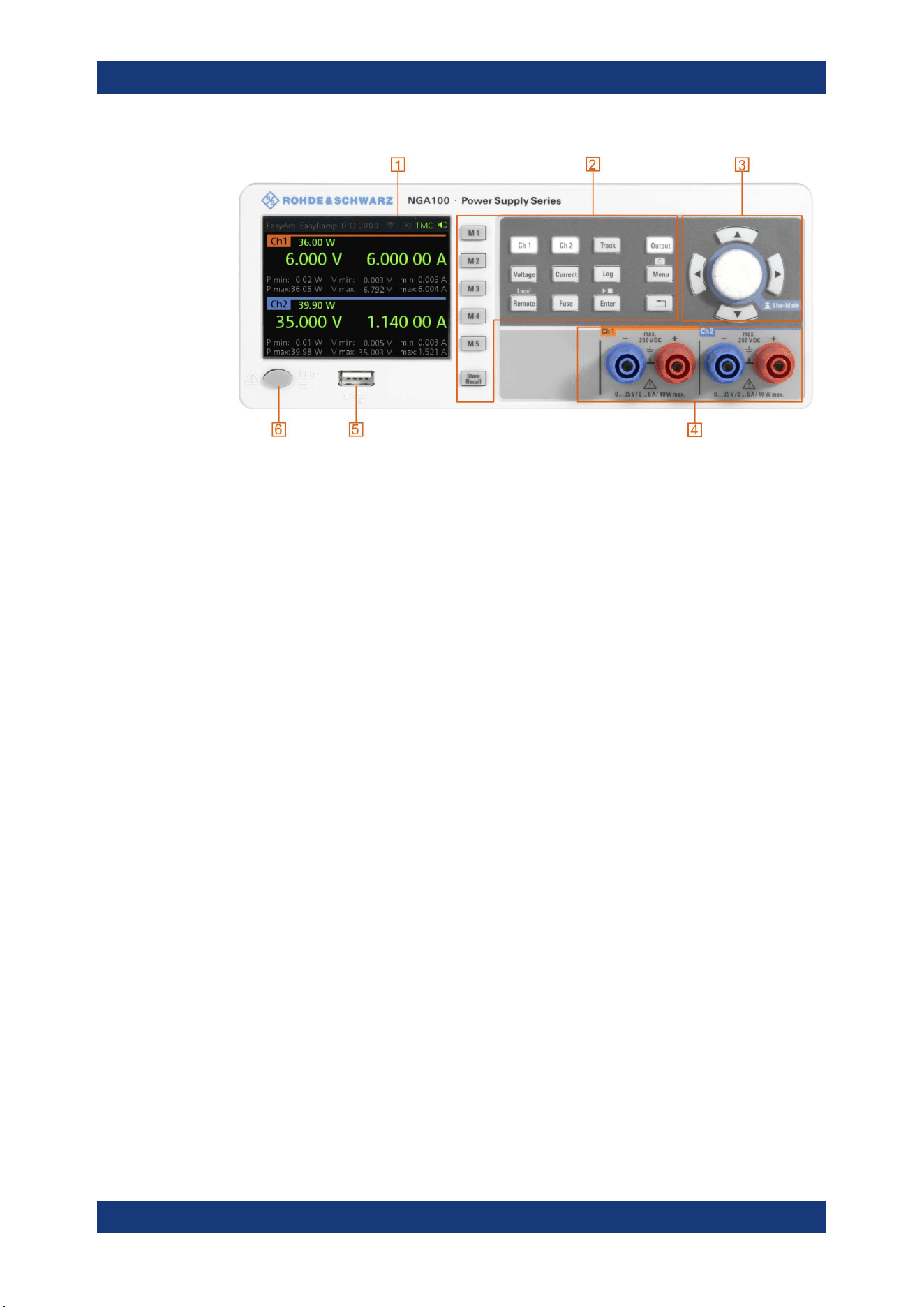
Figure 4-2: Front panel of R&S NGA100 with 2 channels
1 = Display
2 = Function keys
3 = Rotary knob and arrow keys
4 = Output channels (see Table 4-2)
5 = USB connector
6 = Power key
Display (1)
The display is a color LCD screen. Depending on the instrument models, up to two
channels are shown on the screen. The respective measurement settings and func-
tions are displayed in the individual channel section. There is a status bar above the
channel section to indicate the functions used and operation mode of the instrument.
For a detailed description on-screen layout, see section "Screen Layout" in the User
Manual.
Function keys (2)
Function keys are means of input for manual operation of the instrument functions.
When a function key is pressed, all the related keys are also illuminated.
For detailed description on function keys, see section "Function Keys" in the User Man-
ual.
Rotary knob and arrow keys (3)
Rotary knob and arrow keys are means of navigation and adjustment. When pressed
or rotated, they perform tasks like navigation around the screen, adjustment of param-
eter values or confirmation of entries.
For detailed description on rotary knob and arrow keys, see section "Navigation Con-
trols" in the User Manual.
Instrument Tour
Getting Started
R&S
®
NGA100
21User Manual 5601.8919.02 ─ 05
Output channels (4)
Depending on the instrument models, up to two output channels are available for out-
put of power to the connected load. See
Table 4-2.
USB connector (5)
USB Type-A connector is provided for connecting a USB flash drive to perform firm-
ware update, data logging and store screen captures.
The USB flash drive file system supports FAT32 only.
Power key (6)
The [Power] key switches the instrument on and off.
4.2.1.2 Rear Panel
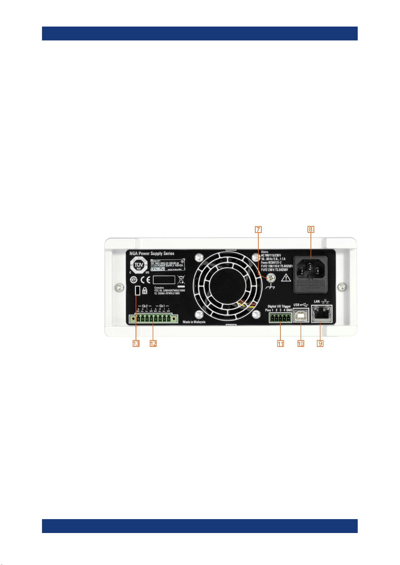
Figure 4-3 shows the rear panel of the R&S NGA100 with its connectors.
Figure 4-3: Rear panel of R&S NGA100
7 = Ground terminal
8 = AC inlet with fuse holder
9 = Ethernet (LAN) connector
10 = USB connector
11 = Digital I/O connector
12 = Rear panel connector
13 = Kensington lock
Ground terminal (7)
M4 screw provides connection to earth ground through the instrument ground/chassis.
Instrument Tour
Getting Started
R&S
®
NGA100
22User Manual 5601.8919.02 ─ 05
AC inlet with fuse holder (8)
Main supply cord
Do not use detachable mains supply cord with inadequate rating.
For safety reasons, the instrument can only be operated with authorized safety sock-
ets.
The power cable must be plugged in before signal circuits can be connected. Never
use the product if the power cable is damaged. See
Chapter 4.2.2, "Switching On the
Instrument"
, on page 23 for more information.
Ethernet connector (9)
This connector is used for establishing remote control via SCPI. See section "Ethernet
Setup" in the user manual for more information on the connection setup.
USB connector (10)
The USB connector is a Type-B connector for remote control operation via USB TMC
or USB VCP.
Digital I/O connector (11)
The Digital I/O connector is a 5-pin terminal block for external trigger input or output.
Measurement control can be achieved by means of an external input signal or as an
output signal to trigger other instruments for some measurements.
The Digital Trigger I/O option (NGA-K103) must be installed for this function to be
available in the instrument.
Rear panel connector (12)
Shock Hazard
Do not turn on AC power when connecting wires to the rear panel connector.
Tightened all wires connected to the terminal block.
Output terminals
Either the output terminals at the front panel or the rear panel connector at the back
panel can be used.
Both terminals should not be used at the same time as it can cause the instrument to
malfunction.
Instrument Tour
Getting Started
R&S
®
NGA100
23User Manual 5601.8919.02 ─ 05
The rear panel connector contains both output ("F+", "F-") and sense ("S+", "S-") con-
nections. Connector for "Ch 2" is only available in the NGA102, NGA142 models.
Kensington security slot (13)
A Kensington lock can be anchored to the R&S NGA100 power supply housing to
secure it to a workstation mechanically.
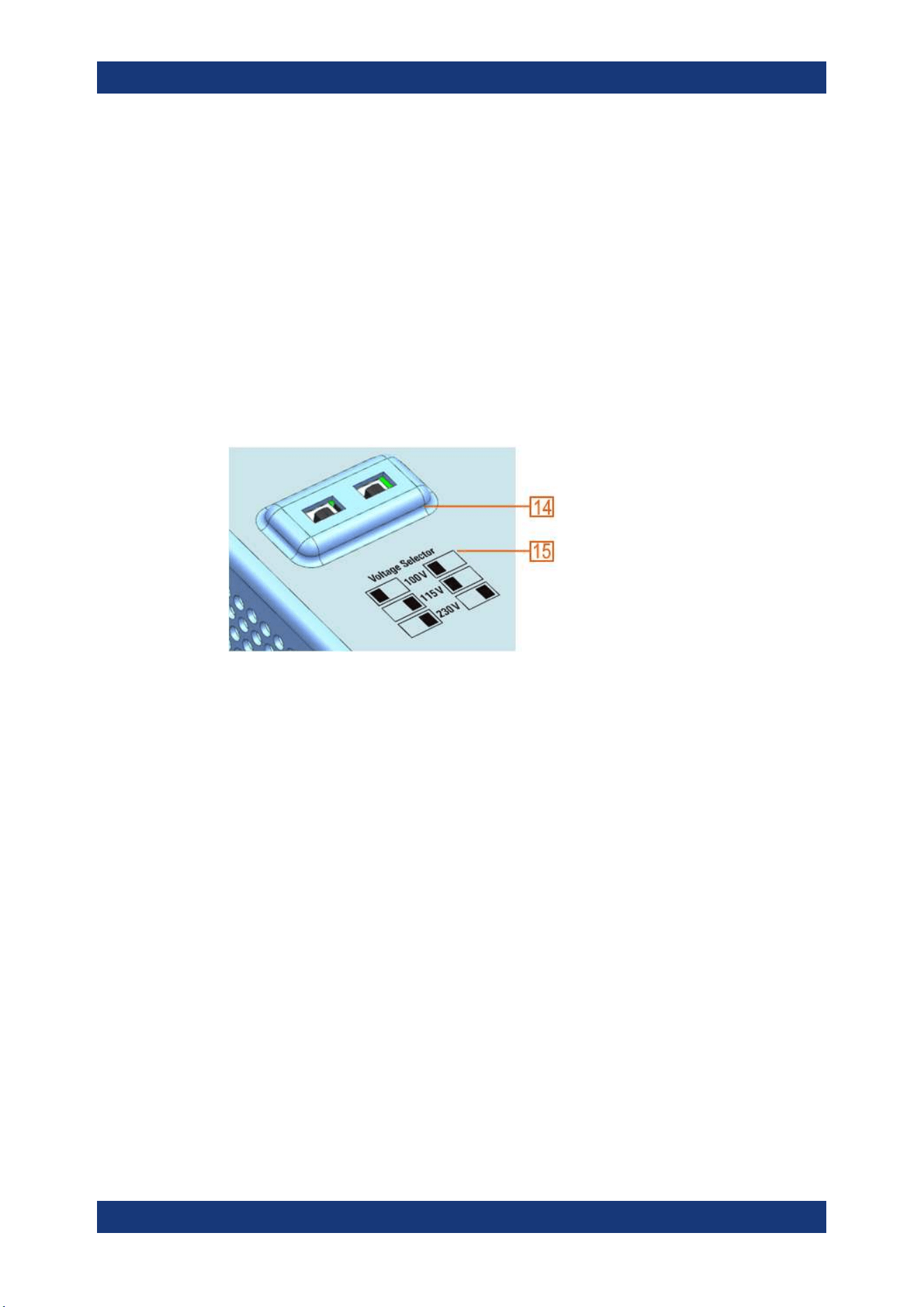
4.2.1.3 Bottom Panel
The voltage selector is located at the bottom panel. On your first power-on connection,
you should see a yellow label sticker attached over the
AC inlet. Before peeling off the
yellow label sticker, make sure that the correct fuse rating is used for the mains volt-
age.
Figure 4-4: Bottom panel of R&S NGA100
14 = Voltage selector
15 = Voltage selector label
Voltage selector (14), Voltage selector label (15)
The voltage selector selects the mains voltage between 100 V, 115 V and 230 V. See
Table 4-1 for the fuse rating.
To set the correct fuse rating, use a tool e.g. a flat screwdriver to move the selector
according to the voltage selector label.
●
To select 100 V, slide both voltage selector to the left
●
To select 115 V, slide both voltage selector facing inward
●
To select 230 V, slide both voltage selector to the right
4.2.2 Switching On the Instrument
Before switching on the instrument, check that all the instructions in the “Basic Safety
Instruction” brochure and safety measures in previous sections are observed.
Also, check if the value on the voltage selector corresponds to the mains voltage (100
V, 115 V or 230 V).
Instrument Tour

Getting Started
R&S
®
NGA100
24User Manual 5601.8919.02 ─ 05
To change the power fuse / mains voltage setting:
1. Peel off the yellow label sticker on the AC inlet.
2. Pull out the fuse holder which is located directly on top of the socket.
3. Remove the preloaded fuses from the fuse holder.
4. Check the rating on the caps of both fuses that you want to change.
By default, the instrument is preloaded with two 230 V fuses.
For more information, see "Voltage selector (14), Voltage selector label (15)"
on page 23.
5. Once verified, insert the fuses into each groove of the fuse holder.
6. Return the fuse holder to its position in the panel.
To switch on the instrument:
1. Connect the power cable to the AC power connector on the rear panel of the R&S
NGA100.
2. Connect the power cable to the socket outlet.
3. Press [Power] key on the front panel.
The instrument performs a system check, boots the operating system and starts
the R&S NGA100 firmware.
By default, all output channels are turned off when the instrument is switched on to
prevent connected loads from being damaged unintentionally.
During startup, the R&S NGA100 is loaded with the last saved instrument settings
from memory location "M1" and auto saved parameters. See Chapter 6.12, "Store
and Recall", on page 57 in the User Manual.
To switch off instrument:
1. Press [Power] key.
2. Disconnect the AC power cable from the socket outlet.
4.3 Trying Out the Instrument
This chapter describes some basic functions that you can perform with the R&S
NGA100.
4.3.1 Selecting the Channels
To select a channel, press the corresponding channel key. The key illuminates.
Trying Out the Instrument

Getting Started
R&S
®
NGA100
25User Manual 5601.8919.02 ─ 05
4.3.2 Setting the Output Voltage and Current Limit
To set the output voltage and current limit via Live-Mode:
1. Long press the rotary knob to enter into editing mode.
By default, the voltage at channel 1 is selected.
2. Use arrow keys to select the desired parameter (voltage or current).
3. Rotate the rotary knob to adjust value.
4. To exist Live-Mode, press the rotary knob.
Alternatively:
1. Press [Voltage] or [Current] key on the front panel.
2. For the two-channel R&S NGA100, press the desired channel key to activate the
respective voltage or current limit setting of that channel. The value on the respec-
tive channel becomes editable and is positioned by a blue cursor.
3. Press the [Left] or [Right] arrow key to move the cursor.
4. Press the [Up]/[Down] arrow key or turn the rotary knob to change the value.
The new value registers immediately.
4.3.3 Activating the Channels Output
The output voltages can be switched on or off regardless of the operating mode of the
instrument.
To activate the channel output, press the [Output] key on the front panel followed by
the desired channel key or vice versa.
For single channel models, press the [Output] key to activate the channel output.
Depending on the instrument operating mode, the display font color changes to green
in CV (constant voltage) mode and red in CC (constant current) mode.
4.3.4 Storing/Recalling of Instrument Settings
The instrument settings can be stored in the instrument memory by long pressing the
[Store Recall] key followed by the desired memory location key ([M1] to [M5]). The pre-
vious saved settings are overwritten.
To retrieve the settings, press [Store Recall] key and select the desired memory loca-
tion key ([M1] to [M5]).
Trying Out the Instrument
Getting Started
R&S
®
NGA100
26User Manual 5601.8919.02 ─ 05
4.4 Maintenance and Support
4.4.1 Maintenance
Regular maintenance improves the life span of the instrument, the following chapter
provides information on instrument maintenance.
Cleaning
Before cleaning the instrument, ensure that it has been switched off and the power
cable is disconnected.
Clean the outer case of the instrument at regular intervals, using a soft, lint-free dust
cloth.
Instrument damage caused by cleaning agents
Use a dry, lint-free cloth to clean the product. When cleaning, keep in mind that the
casing is not waterproof. Do not use any liquids for cleaning.
Cleaning agents, solvents (thinners, acetone), acids and bases can damage the front
panel labeling, plastic parts and display.
The display may only be cleaned with an appropriate glass cleaner. Rub the display
with a dry, clean and lint-free cloth. Do not allow cleaning fluid to enter the instrument.
Internal battery replacement
An internal CR2032 coin cell battery powers the real-time clock circuit which provides
continuous time stamp for the instrument. If the battery fails, the system clock and time
stamp for the logging function are not available but other instrument functions are not
affected.
Under normal usage at room temperature, the battery is expected to last up to 10
years. However, the battery life expectancy is reduced if the device is stored at temper-
ature above 40°C for an extended period of time.
If the instrument cannot retain the date and time settings after turning off the AC input,
the battery is discharged.
Contact your local service partner for battery replacement.
Maintenance and Support

Getting Started
R&S
®
NGA100
27User Manual 5601.8919.02 ─ 05
4.4.2 Contacting Customer Support
Technical support – where and when you need it
For quick, expert help with any Rohde & Schwarz product, contact our customer sup-
port center. A team of highly qualified engineers provides support and works with you
to find a solution to your query on any aspect of the operation, programming or applica-
tions of Rohde & Schwarz products.
Contact information
Contact our customer support center at
www.rohde-schwarz.com/support, or follow this
QR code:
Figure 4-5: QR code to the Rohde
&
Schwarz support page
Maintenance and Support
Operating Basics
R&S
®
NGA100
28User Manual 5601.8919.02 ─ 05
5 Operating Basics
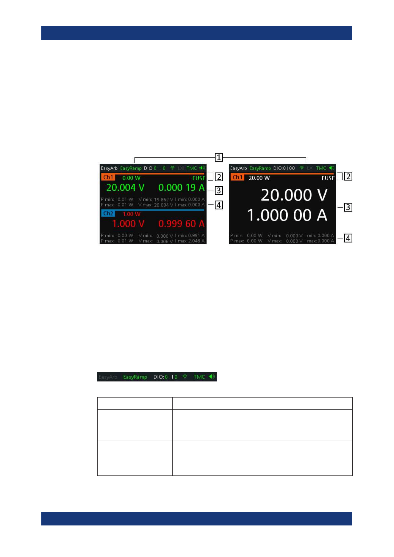
5.1 Display Overview
The following displays the screen layout of R&S NGA100. It shows the output voltage,
current level and status bar information of the instrument.
Figure 5-1: Screen layout of R&S NGA100 for two-channel and single channel display
1 = Device status bar
2 = Channel status bar
3 = Channel display area
4 = Channel history information
5.1.1 Status Bar Information
There are two types of status bar. One shows device status information and the other
shows the individual channel status information.
Device status bar
Table 5-1: Status bar function
Function Description
EasyArb Arbitrary output sequences on Ch 1.
If in use, the icon is highlighted in green.
If enabled, the icon is highlighted in white else it shows gray.
EasyRamp Output voltage to ramp continuously within a 10 ms to 10 s until set volt-
age, V
set
.
If in use for any channel, the icon is highlighted in green else it shows
gray.
Display Overview
Operating Basics
R&S
®
NGA100
29User Manual 5601.8919.02 ─ 05
Function Description
DIO:xxxx Digital Trigger I/O (Digital Trigger I/O option NGA-K103 must be installed).
The "xxxx" refers to I/O status for DIO1, DIO2, DIO3, DIO4.
If in use, the icon is highlighted in green.
If enabled, the icon is highlighted in white.
If disabled or option not installed, the icon is highlighted in gray.
Wireless LAN connection (WLAN option R&S NGA-K102 must be instal-
led).
If connected to access point, the icon is highlighted in green. It shows yel-
low when connecting to access point.
If disconnected or disabled, the icon is highlighted in gray.
TMC/VCP USB connection with USB-VCP or USB-TMC setting.
If TMC or VCP is selected, the icon is highlighted in green.
Indicate buzzer state ("Disabled", "Fault Events", "Any Events").
If speaker is enabled, the icon is highlighted in green, else it shows gray.
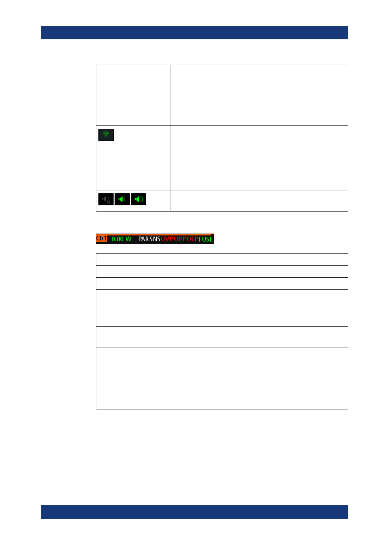
Channel status bar
Function Description
Channel number Channel number indication.
Power Display output power in watt.
SER/PAR Indicator to show the series or parallel mode if chan-
nel fusion is enabled.
Available only for the two-channel models.
If enabled, the indicator displays in white.
SNS Remote sense status indication.
If enabled, the indicator displays in green.
OVP / OPP / OTP Indicator to show that the overload voltage, power or
temperature protection is triggered.
When triggered, the indicator shows flashing and
displays in red.
Fuse Indicator to show the fuse status (on or off).
When triggered, the indicator shows flashing and
displays in red.
5.1.2 Channel Display Area
The R&S NGA100 displays two channels display area (Ch 1, Ch 2) for NGA102 and
NGA142 and a single channel display area for NGA101 and NGA141. The respective
channel settings and functions are displayed for each channel.
Display Overview
Operating Basics
R&S
®
NGA100
30User Manual 5601.8919.02 ─ 05
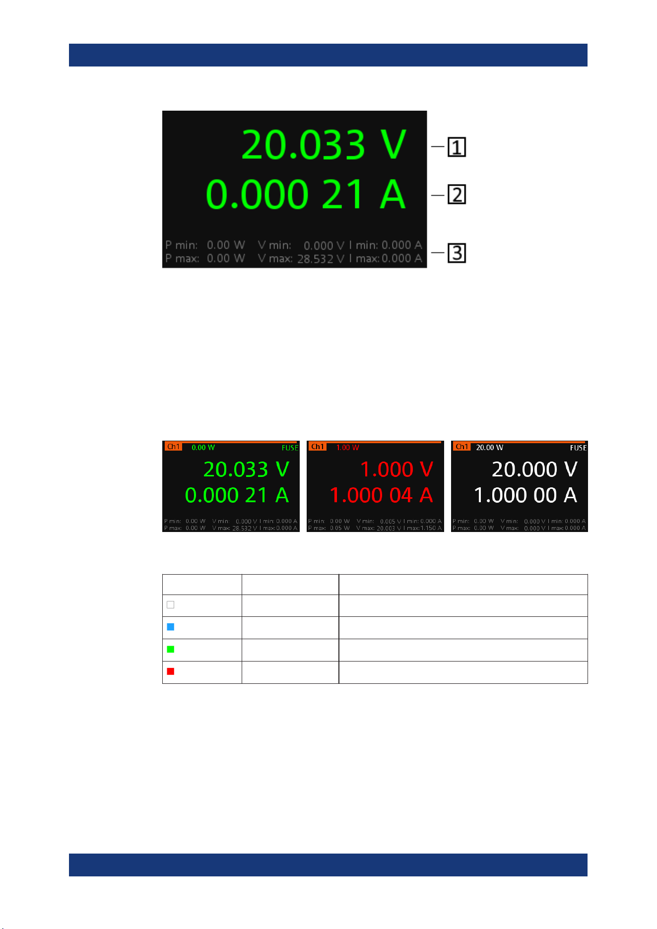
Figure 5-2: Channel display area for one-channel model
1 = Output voltage displays in volt. The display resolution for voltage is three digits after the decimal point
2 = Output current displays in ampere. The display resolution for current is five digits after the decimal point
3 = Channel history information displaying the historical maximum and minimum channel information (P min,
P max, V min, V max, I min and I max)
Operating mode
Different font colors on the screen are used to differentiate the various output status
and operating conditions of the instrument. It is easy to know and confirm the different
output status and operating conditions of the instrument by looking at the colors.
Figure 5-3: Color coding of difference operating conditions
Color Operating mode Description
OFF mode Output is OFF
Editing mode A solid blue cursor is shown when an item is selected.
CV mode Active outputs are operated in a constant voltage mode.
CC mode Active outputs are operated in a constant current mode.
5.2 Front Panel Keys
For an overview of the front panel keys, see Figure 4-2.
Front Panel Keys
Operating Basics
R&S
®
NGA100
31User Manual 5601.8919.02 ─ 05
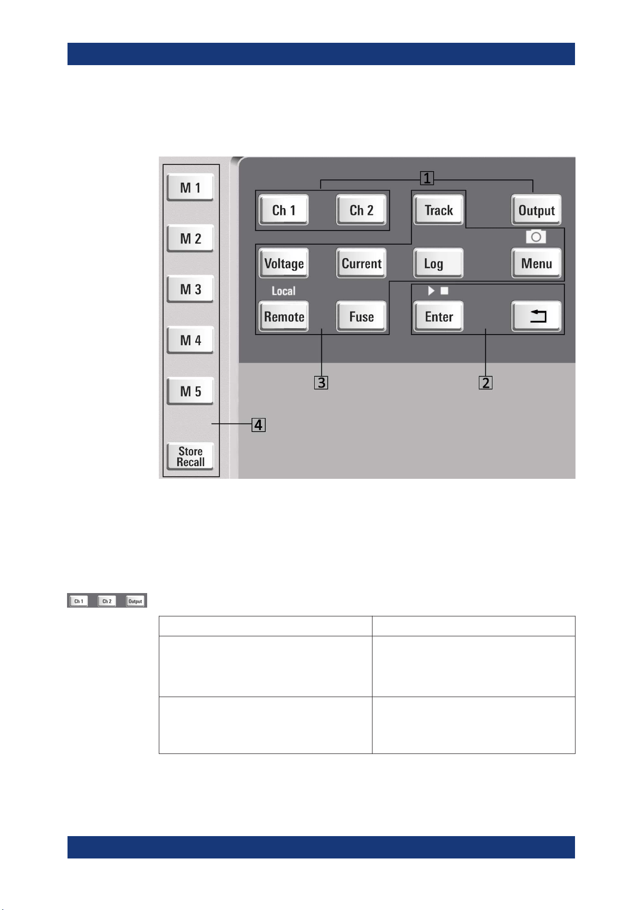
5.2.1 Function Keys
The keys can be categorized based on their functions.
1 = Output and channel controls
2 = Navigation keys
3 = Instrument functions
4 = Memory functions
5.2.1.1 Output and Channel Controls
These keys control the channel output settings of the instrument.
Function keys Description
[Ch 1], [Ch 2] Selects the respective channel for output.
Applicable only for the two-channel models
See Chapter 6.1, "Setting the Channels Voltage
and Current", on page 40.
[Output] Master output switch - it turns output for all
selected channels on or off.
See Chapter 4.3.3, "Activating the Channels Out-
put", on page 25
Front Panel Keys
Operating Basics
R&S
®
NGA100
32User Manual 5601.8919.02 ─ 05
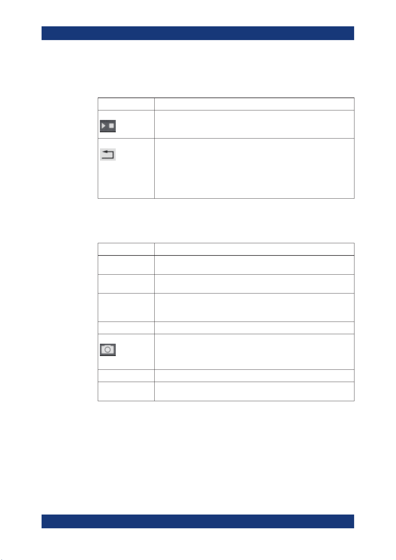
5.2.1.2 Navigation Keys
These keys provide navigation control in the instrument.
Function keys Description
Enter Confirms menu selection or entry in dialog boxes.
Start and stop (long press) the EasyArb function. See Chapter 6.11.1, "EasyArb",
on page 54.
Back Returns to the previous menu level or exit the menu mode.
In the menu dialog, press the [Back] key to discard changes and restore the previ-
ous value.
In the channel display area, press the [Back] key to exit editing mode and keep the
changes made.
Long press on the [Back] key resets the channel history information. See Fig-
ure 5-2.
5.2.1.3 Instrument Functions
These keys control the channel output settings and instrument functions.
Function keys Description
Voltage Sets the output voltage for the channel. See "Set output voltage and current"
on page 40.
Current Sets the output current limit for the channel. See "Set output voltage and current"
on page 40.
Track Applicable only for the two-channel instrument models.
Configures the tracking function. See Chapter 6.7, "Tracking Function",
on page 48.
Log Toggles the data logging on/off. See Chapter 6.10, "Data Logging", on page 53
Menu Main menu of the instrument. See Chapter 5.2.3, "Menu Key", on page 34.
Long press on [Menu] key to capture screenshot on the USB stick. The default
screenshot filename starts with a prefix nga100_scr_ follows by an ascending
index 000-999 (e.g. nga100_scr_001.bmp).
Remote Long press on [Remote] key to switch from remote to local control mode.
Fuse Toggles the fuse on/off. See
Chapter 6.6.1, "Fuse Delay, Fuse Linking",
on page 47.
5.2.1.4 Memory Functions
These keys are dedicated for a specific preprogrammed function.
Front Panel Keys
Operating Basics
R&S
®
NGA100
33User Manual 5601.8919.02 ─ 05
Function keys Description
M1 to M5 Five memory keys to save or recall instrument settings.
Store Recall Saves/loads instrument settings. See Chapter 6.12, "Store and Recall",
on page 57.
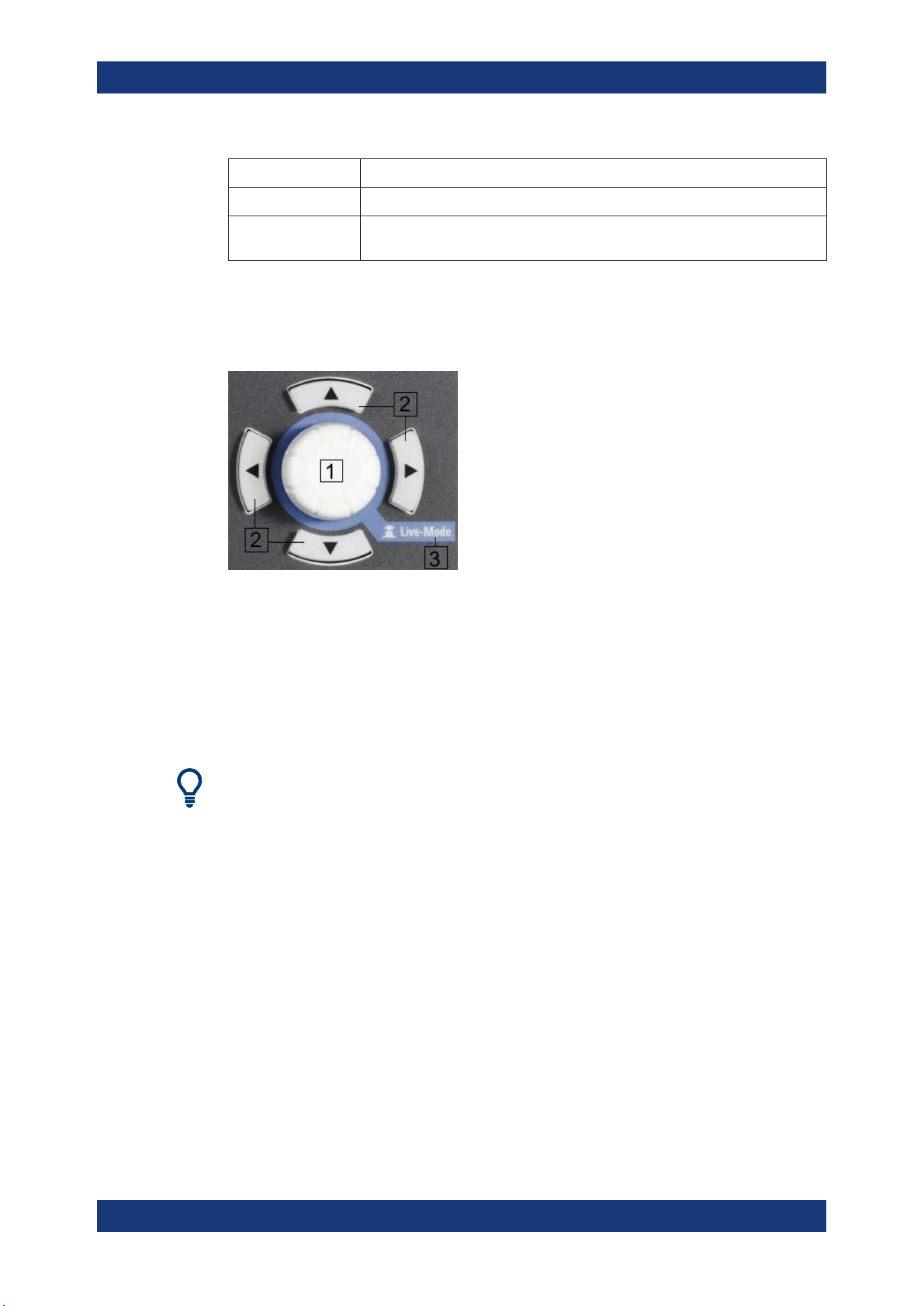
5.2.2 Navigation Controls
Navigation and value setting are done via the rotary knob and arrow keys.
Figure 5-4: Navigation control
1 = Rotary Knob
2 = Arrow keys
3 = Live-mode
5.2.2.1 Rotary Knob
Step size changes of the numeric value correspond to the speed of the rotary knob.
The rotary knob has several functions depending on the mode it is in:
●
Increments (clockwise direction) or decrements (counter-clockwise direction) any
kind of numeric value when in editing mode.
●
Navigates down (clockwise direction) or up (counterclock-wise direction) the menu
or menu items when rotated.
●
Acts as an [Enter] key when pressed.
●
Enter editing mode when pressed.
●
Enter
Live-mode when long pressed.
5.2.2.2 Arrow Keys
Using arrow keys, you can do several things:
Front Panel Keys
Operating Basics
R&S
®
NGA100
34User Manual 5601.8919.02 ─ 05
●
The up and down keys increase or decrease any kind of numeric value when in
editing mode.
●
Navigate through the menu or menu items in the dialog box.
●
Long press on the up and down keys increase or decrease the numeric value of
the menu items to maximum or minimum value in menu dialog (e.g. fuse dialog,
protection dialog, EasyArb and EasyRamp dialog, etc)
To stop the increasing or decreasing of value, press the rotary knob.
●
The left and right keys move the cursor in an input field in the corresponding direc-
tion.
5.2.2.3 Live-Mode
When the instrument goes into the Live-mode, all the arrow keys are illuminated.
The instrument automatically sets the Ch 1 voltage to editing mode. See
Figure 5-3.
You can navigate to other channel settings by using the arrow keys to edit the voltage
and current values.
The duration of Live-mode depends on the
key fallback time. Set a longer fallback time
if you need more time in this mode.
To exit Live-mode, press the rotary knob.
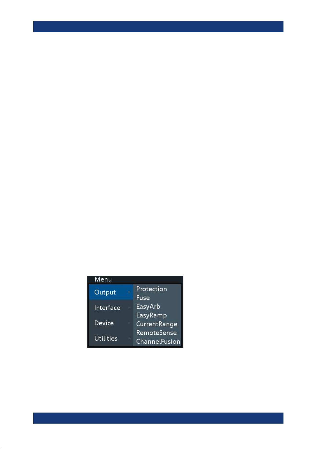
5.2.3 Menu Key
The R&S NGA100 [Menu] key provides access to instrument's functions and general
instrumental settings. You can also obtain the instrument and service information via
the [Menu] key.
To access this mode:
1. Press [Menu] key on the front panel. The main menu screen appears.
Figure 5-5: Main menu
2. Navigate the menu via the rotary knob or arrow keys.
3. Press the rotary knob or [Enter] key to enter the submenu.
Front Panel Keys
Operating Basics
R&S
®
NGA100
35User Manual 5601.8919.02 ─ 05
4.
Press
key to return to the previous menu level or exit the menu mode if it is
already at the main menu level. Alternatively, press [Menu] key to exit the menu
mode from any menu level.
Table 5-2: Main menu hierarchy
Menu Descriptions
Output Menu items related to the instrument's output functions.
Interface Menu items related to connection setup.
Device Menu items related to the instrument's general settings, reset function and infor-
mation about the instrument.
Utilities Menu items such as system test, firmware update function and information for
service.
Table 5-3: Output menu hierarchy
Menu Menu items Descriptions
Output Protection Configures the OVP and OPP protection settings for the
instrument. See Chapter 6.8, "Protection", on page 48.
Fuse Configures the fuse delay and fuse linking function of the
channel. See Chapter 6.6.1, "Fuse Delay, Fuse Linking",
on page 47.
EasyArb Programs the waveform of the instrument voltage and cur-
rent settings for Ch 1. See Chapter 6.11.1, "EasyArb",
on page 54.
EasyRamp Configures the ramping time of the voltage for selected
channel. See Chapter 6.11.2, "EasyRamp", on page 56.
CurrentRange Configures the current range used for readback measure-
ment. See Chapter 6.3, "Current Range", on page 42.
RemoteSense Configures the voltage compensation on cables connected
to the load. See Chapter 6.4, "Remote Sense Function",
on page 43.
ChannelFusion Configures the channel fusion mode. See Chapter 6.5,
"Channel Fusion", on page 44.
Table 5-4: Interface menu hierarchy
Menu Menu items Descriptions
Interface Ethernet Configures the Ethernet interface. See Figure 6-15.
WLAN Configures the WLAN interface. See Figure 6-16.
The WLAN option NGA-K102 must be installed for this
function to be available in the instrument.
Front Panel Keys
Operating Basics
R&S
®
NGA100
36User Manual 5601.8919.02 ─ 05
Menu Menu items Descriptions
Digital IO Configures the Digital Trigger I/O settings. See Fig-
ure 6-10.
The Digital Trigger I/O option NGA-K103 must be installed
for this function to be available in the instrument.
USB Configures the USB connection. See Figure 6-18.
Requires restart of the instrument to apply the setting.
Table 5-5: Device menu hierarchy
Menu Menu items Descriptions
Device Information Displays instrument information. See Chapter 6.14.1,
"Instrument Information", on page 68.
General Configures general instrument settings. Chapter 6.14.2,
"General Instrument Settings", on page 69.
License Displays license information and install license options.
See Chapter 6.14.3, "Managing Options", on page 69.
Reset Resets instrument to factory default settings. See Chap-
ter 6.14.4, "Reset Instrument", on page 70.
Table 5-6: Utilities menu hierarchy
Menu Menu items Descriptions
Utilities System Test Provides self-test function for display screen, keypad back-
light, beeper and fan. See Chapter 6.14.5, "System Test",
on page 72.
Update Performs firmware update on the instrument. See Chap-
ter 6.14.6, "Updating the Firmware", on page 72.
Service This function is restricted for service personnel only.
Date Time Configures system date and time. See Chapter 6.14.8,
"Date Time", on page 74.
Help Provides help information for the instrument. See Chap-
ter 6.14.7, "Help", on page 74.
5.3 On-screen Keyboard
The on-screen keyboard allows you to input symbols and alphanumeric characters in
the input field. It can be invoked whenever there is an input field.
On-screen Keyboard

Operating Basics
R&S
®
NGA100
37User Manual 5601.8919.02 ─ 05
Figure 5-6: Virtual keyboard
Invoke the on-screen keyboard as follows:
1. Move the cursor to the desired input field.
2. Press [Enter] key. The on-screen keyboard appears.
3. Once on the keyboard screen, press the arrow keys or turn the rotary knob to go to
the desired character.
4. Press the rotary knob to select the character.
Select
key if you want to create a space between characters.
To delete the last entered character, select the
key.
To delete the current entry, select the
key.
Select the
key to alternate between capital and small capital letters.
5. Repeat step 3 and 4 until all the characters are entered.
6. Select "OK" to confirm the input and exit the screen.
Select "ESC" or press [Menu] key to exit the screen without saving the changes.
5.4 Power Derating
The R&S NGA100 power supply series provides a maximum output power of 40 W for
a single channel model. Depending on the power supply models, up to 80 W of output
power is provided for models with two identical channels with a continuous voltage
range of 0 V to 35 V or 0 V to 100 V.
Combination of the set voltage and current limit results in the following output perfor-
mance graph.
Power Derating

Operating Basics
R&S
®
NGA100
38User Manual 5601.8919.02 ─ 05
Figure 5-7: Output performance graph
According to the basic electrical formula for power (P) = current (I) x voltage (V), the
following results for the maximum power per channel:
●
NGA101, NGA141: 40.0 W for single channel
●
NGA102, NGA142: 40.0 W per channel (80 W max for the combination of two
channels)
For more information on the combination of channels, see
Chapter 8.1, "Parallel and
Series Mode"
, on page 110.
5.5 Operation Modes
The R&S NGA100 operates in two different modes, i.e. CV and CC. The instrument
switches automatically between CV and CC depending on the connected load.
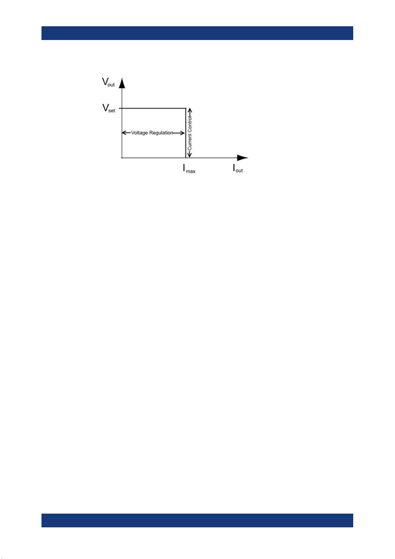
CV mode
Figure 5-8 shows that if the instrument is in the range of voltage regulation, the output
voltage V
out
remains constant while the current may increase to its maximum value I
max
when the connected load is increasing. In CV mode, the font text in the channel display
area changes to green.
See
Figure 5-3
Operation Modes
Operating Basics
R&S
®
NGA100
39User Manual 5601.8919.02 ─ 05
Figure 5-8: Current limit
CC mode
The current I
max
corresponds to the current setting adjustable in the instrument.
If I
out
reaches I
max
, the instrument switches to CC mode, i.e. the output current remains
constant and limited to I
max
even if the load increases. Instead, the output voltage V
out
decreases below V
set
. In a short circuit, the output voltage drops towards zero. In CC
mode, the font text in the channel display area changes to red.
See
Figure 5-3
Operation Modes
Instrument Functions
R&S
®
NGA100
40User Manual 5601.8919.02 ─ 05
6 Instrument Functions
6.1 Setting the Channels Voltage and Current
The R&S NGA100 comes with the following instrument models:
Model Voltage Current
NGA101, NGA102 0 V to 35 V <= 6 V: 6A
> 6 V to 9 V: 40 W
> 9 V to 20 V: 2 A
> 20 V to 35 V: 40 W
NGA141, NGA142 0 V to 100 V <= 20 V: 2 A
> 20 V to 25 V: 40 W
> 25 V to 54 V: 0.75 A
> 54 V to 100 V: 40 W
Depending on models, toggle the respective channel key ([Ch 1] or [Ch 2] ) on the front
panel to select these channels. When a channel is selected, the respective channel
key illuminates. See
Figure 6-1.
Figure 6-1: Ch 1 key illuminates when selected
Set output voltage and current
Voltage, current settings
If "Arbitrary" function of a Ch 1 is enabled, the channel voltage or current setting is dis-
abled.
See
"EasyArb function" on page 54.
Depending on the instrument models, the R&S NGA100 adjusts the voltage and cur-
rent values with the following step size.
NGA101, NGA102 NGA141, NGA142
1 mV 10 mV
1 mA 1 mA
The setting of current value corresponds to the I
max
of the respective channel. It is
advisable to set the current limit before operating the instrument to prevent damage to
the load and instrument in the case of malfunction like short-circuit.
Setting the Channels Voltage and Current
Instrument Functions
R&S
®
NGA100
41User Manual 5601.8919.02 ─ 05
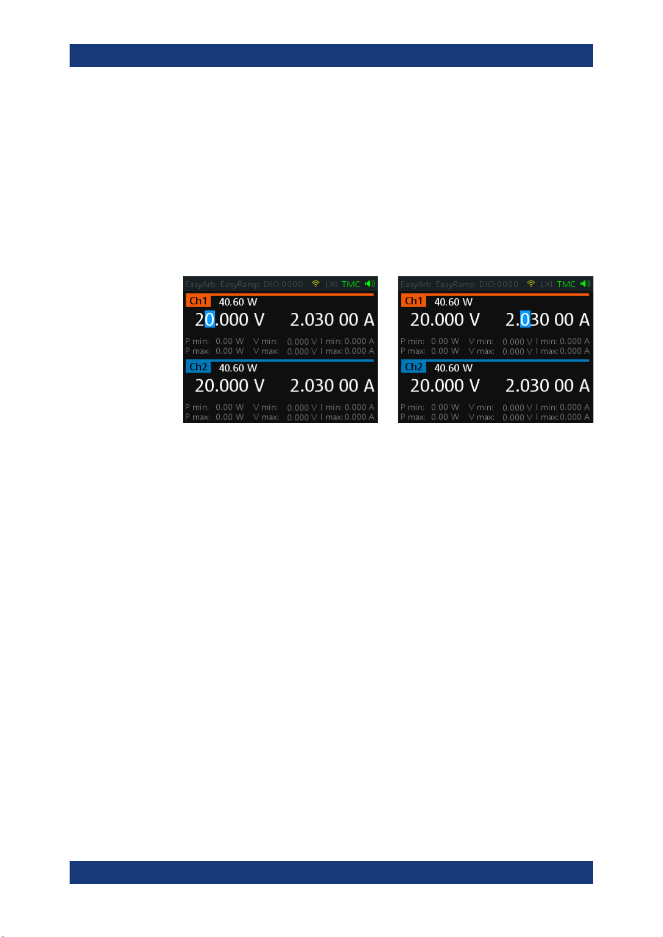
1. Press [Voltage] or [Current] key.
The previous set channel is selected.
The channel font changes to blue and all the navigation controls illuminate.
Selected [Voltage] or [Current] key and the channel key are also illuminated.
2. Press the desired channel key to switch to that channel.
Selected channel key ([Ch 1], [Ch 2]) illuminates.
3. Enter the desired voltage or current value.
4. Press the rotary knob, [Voltage]/[Current] or [Enter] key to confirm the value.
The selected channel font text changes to yellow.
Figure 6-2: Voltage and current settings in the instrument
See
Chapter 5.2.2.3, "Live-Mode", on page 34 for alternative way to configure the volt-
age and current values.
See also
General Instrument Settings on the keypad for setting the fallback time.
6.2 Activating the Channel Output
Depending on the models, the outputs of the channels (Ch 1, Ch 2) can be switched on
or off by toggling the [Output] key on the front panel.
By default, the output is turned off when the instrument is switched on.
1. For two-channel models, press the required channel key.
Selected channel key (Ch 1, Ch 2) illuminates.
2. Press [Output] key.
The R&S NGA100 outputs the set voltage on the channel.
Depending on the operating mode, the font text in the channel display area shows
green in CV mode and red in CC mode.
See
Chapter 5.5, "Operation Modes", on page 38.
See also Chapter 5.4, "Power Derating", on page 37.
Multiple outputs can be turned on or off at the same time.
Activating the Channel Output
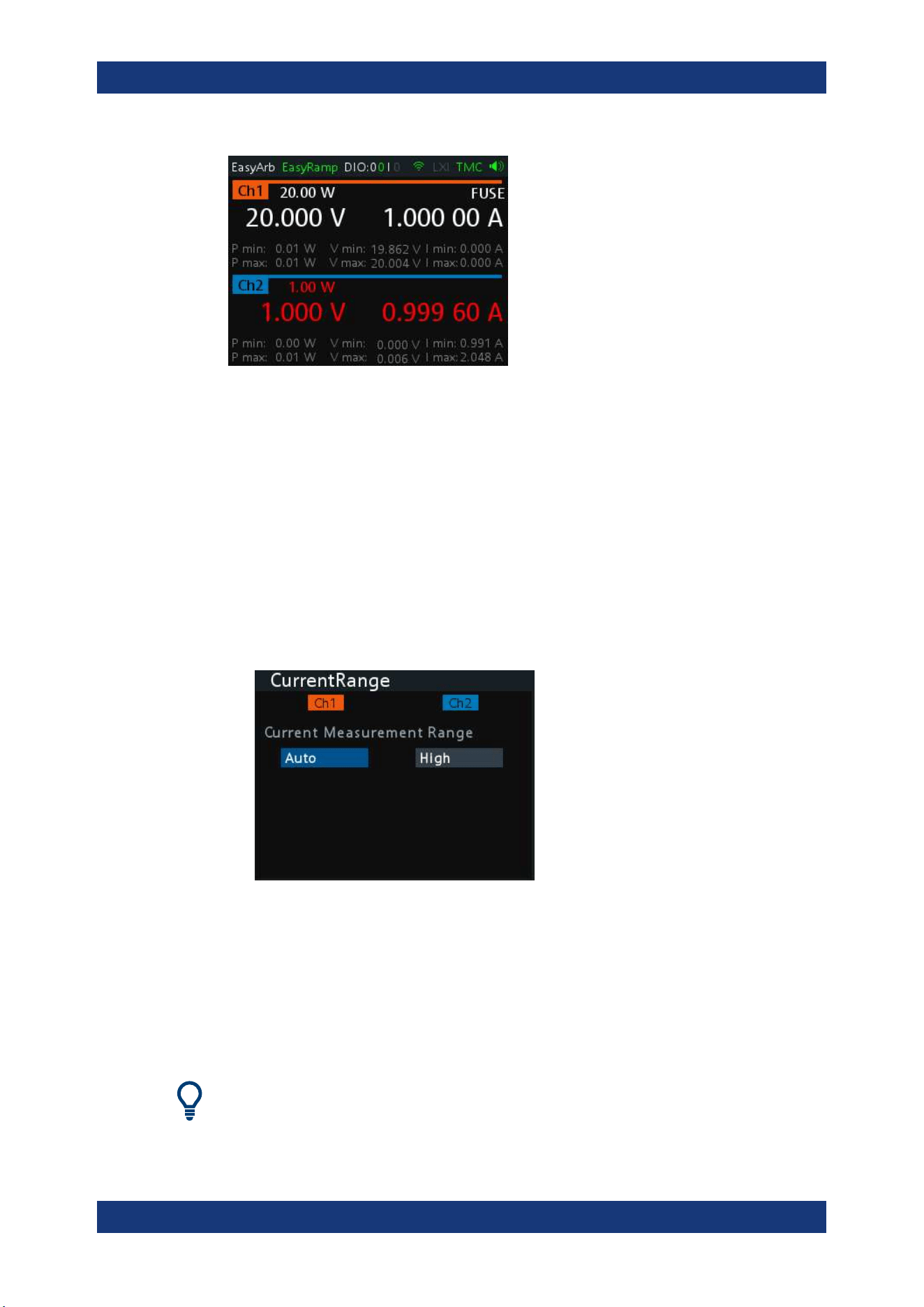
Instrument Functions
R&S
®
NGA100
42User Manual 5601.8919.02 ─ 05
Figure 6-3: Output of Ch2 in CC mode
6.3 Current Range
The "CurrentRange" dialog provides the configuration to set the measured output cur-
rent range.
1. Press [Menu] key on the front panel.
The main menu screen appears.
2. Select "Output" > "CurrentRange" menu item to configure current range setting.
The R&S NGA100 displays the "CurrentRange" dialog.
3. Set the required current range for respective channel.
● "High": The measured output current is displayed in "A" with 10 µA resolution
● "Low": The measured output current is displayed in "mA" with 1 µA resolution
If output current exceeds 200 mA, the "OVLD" information is displayed
● "Auto": The measured output current is displayed in the following:
– "A" with 10 µA resolution for current above 200 mA
– "mA" with 1 µA resolution for current below 200 mA
"High" current readback range is tested for 100uA resolution per specification.
Current Range
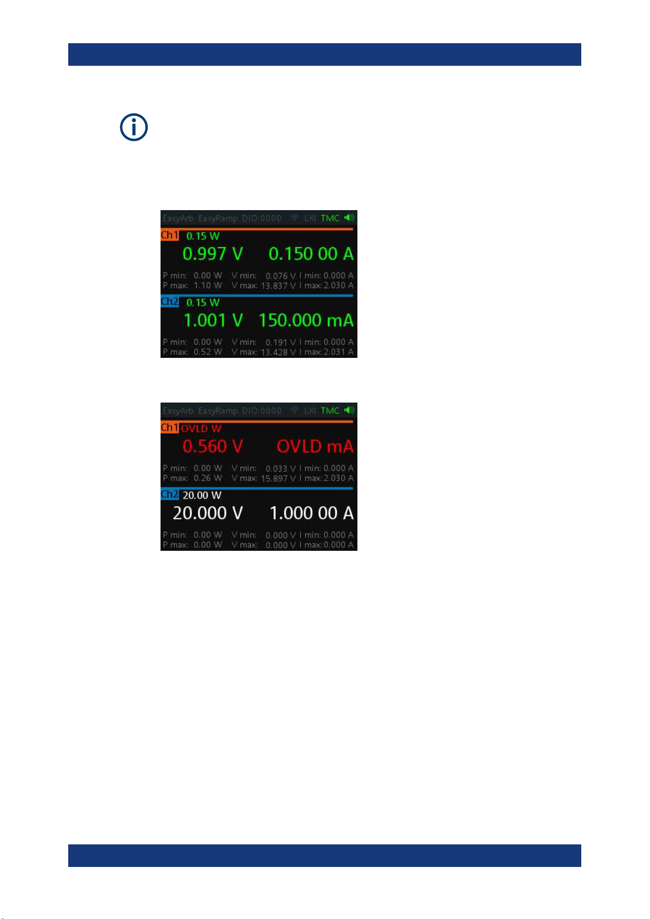
Instrument Functions
R&S
®
NGA100
43User Manual 5601.8919.02 ─ 05
To avoid oscillation in "Auto" mode, the "Low" range to "High" range switching point is
at 210 mA and the "High" range to "Low" range switching point is at 170 mA.
Example:
The following shows the displays of current range set to "High" for Ch 1 and "Low" for
Ch 2.
If output current has exceeded 200 mA when current range is set "Low", the "OVLD"
information is displayed.
6.4 Remote Sense Function
The "Remote Sense" is a mechanism used to monitor and compensate the voltage
drops on the cables connected to the load.
1. Press [Menu] key.
2. Select "Output" > "Remote Sense" menu item to configure the remote sense mode.
The R&S NGA100 displays the "Remote Sense" dialog.
Remote Sense Function
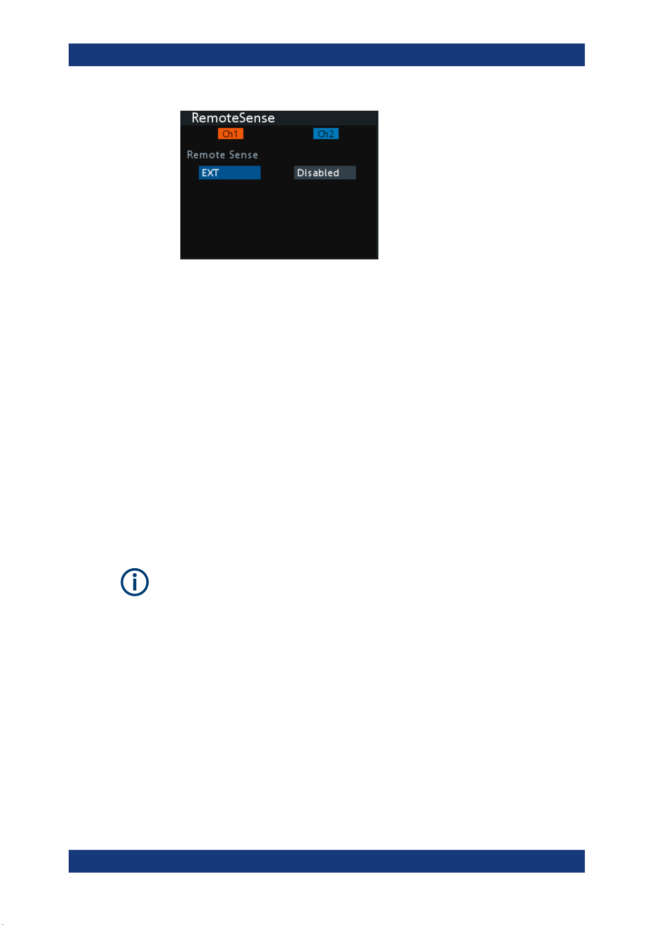
Instrument Functions
R&S
®
NGA100
44User Manual 5601.8919.02 ─ 05
3. Select the required remote sense mode for selected channels.
● "EXT": The internal voltage sense relay in the instrument is switched on and
the connection of remote sense wires (S+, S- ) to the input of the load become
necessary. Failure to connect remote sense can cause overvoltage or unregu-
lated voltage output from the R&S NGA100. The voltage sense relay remains
switched on even when output is turned off.
● "Disabled" : Remote sense connection is disabled.
6.5 Channel Fusion
The "ChannelFusion" provides configuration to set the connection mode (series or par-
allel) of the device. The R&S NGA100 has an internal series link to connect Ch 1 and
Ch 2 if series mode is configured.
The device operates as a 1-channel device which combines both Ch 1 and Ch 2 out-
put.
For more information, see
Chapter 8.1, "Parallel and Series Mode", on page 110.
The "ChannelFusion" is available only in the two-channel models.
1. Press [Menu] key on the front panel.
The main menu screen appears.
2. Select "Output" > "ChannelFusion" menu item to configure channel fusion mode.
The R&S NGA100 displays the "ChannelFusion" dialog.
Channel Fusion
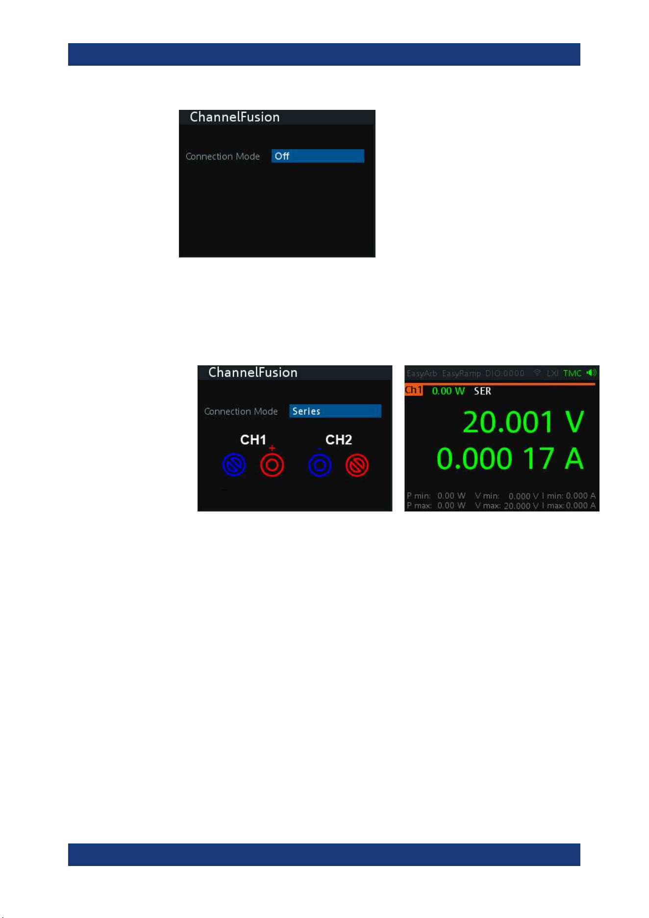
Instrument Functions
R&S
®
NGA100
45User Manual 5601.8919.02 ─ 05
3. Set the required channel fusion mode:
● "Off": Channel operates separately
● "Series": In series mode, the two terminals in the middle are used for output.
There is an internal series link activated to connect channel 1 and channel 2
output. If this series mode is set, a "SER" indicator is displayed on the channel
status bar. For details, see Chapter 8.1.1, "Series Mode", on page 110
Figure 6-4: Series mode setting and output of one-channel display
Note: The "Digital IO", "EasyArb" and "EasyRamp" functions are disabled in
this mode.
● "Parallel": In parallel mode, an external wire is required to connect the "CH1"
and "CH2" terminals. All channels can be used as output. If parallel mode is
set, a "PAR" indicator is displayed on the channel status bar. See
"Channel sta-
tus bar" on page 29.
Channel Fusion

Instrument Functions
R&S
®
NGA100
46User Manual 5601.8919.02 ─ 05
Figure 6-5: Parallel mode setting and output of one-channel display
See also
Chapter 8.1.2, "Parallel Mode", on page 111.
Note: The "Digital IO", "EasyArb", "EasyRamp" and "CurrentRange" functions
are disabled in this mode.
6.6 Activating Fuse
To protect a connected, sensitive output in general, the R&S NGA100 power supply
includes an electronic fuse which can be switched on individually for each channel.
A fuse delay can be applied to each channel and individual electronic fuses can be log-
ically linked to switch off the interlinked channels if a fuse triggers.
For more information, see
Chapter 6.6.1, "Fuse Delay, Fuse Linking", on page 47 for
fuse delay and fuse linking configuration.
1. Turn off the output before activating the fuse for each channel.
2. Press [Fuse] key.
The R&S NGA100 activates the fuse function and the [Fuse] key illuminates.
Activated fuses are also illuminated on channel keys for the two-channel models.
3. For the two-channel models, press the desired channel to activate or deactivate
the fuse.
For the single-channel models, toggle the [FUSE] key to activate or deactivate the
fuse.
Selected channel key ([Ch 1], [Ch 2] ) illuminates.
On the channel display area, the "FUSE" is indicated on selected channels.
4. Repeat step 1 and step 2 to disable the fuse function.
Activating Fuse
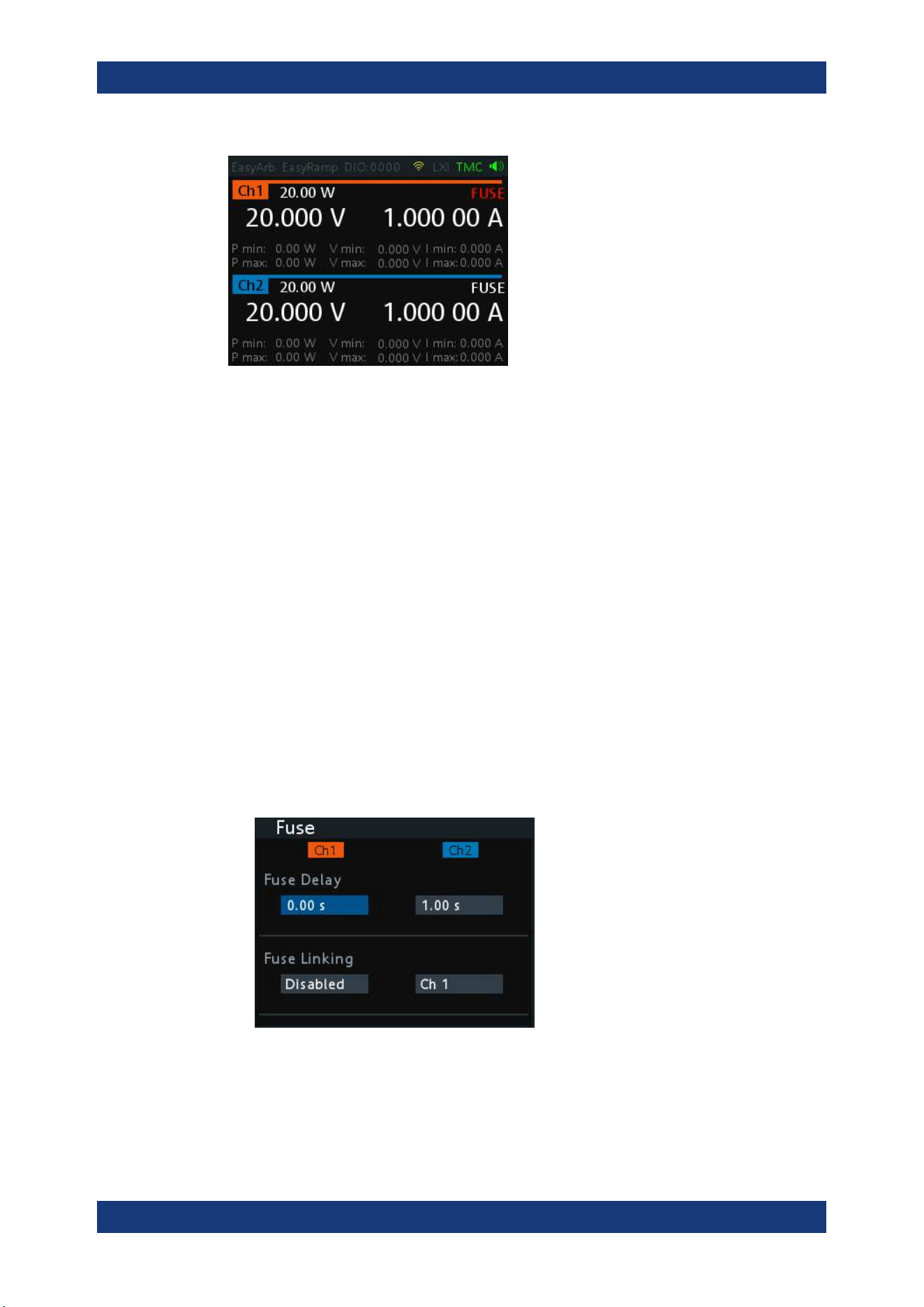
Instrument Functions
R&S
®
NGA100
47User Manual 5601.8919.02 ─ 05
Figure 6-6: Fuse indicator on respective channel
6.6.1 Fuse Delay, Fuse Linking
The fuse delay and fuse linking functions provide the flexibility to handle a fuse tripped
event when it occurs. When a fuse tripped event triggered, the affected channels are
turned off according to the settings configured in the fuse delay and fuse linking.
With fuse delay function, it allows you to ignore the current peaks set above the current
limit that occurs during the time set in the fuse delay. This prevents the fuse to be trig-
gered in case of a capacitive load.
With fuse linking function, it allows you to logically interlink channels with their elec-
tronic fuses. If a fuse trips during operation, all channels interlinked with this channel
are turned off.
See
Chapter 6.6, "Activating Fuse", on page 46 for more information.
1. Press [Menu] key.
2. Select "Output" > "Fuse" menu item.
The R&S NGA100 displays the "Fuse" dialog. See
Figure 6-7.
Figure 6-7: Fuse dialog
3. Set "Fuse Delay" to a desire value.
You can set a value from 0 s to 10 s in a 0.01 s step size.
Activating Fuse
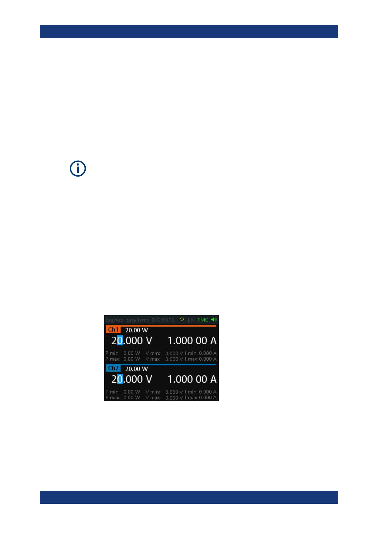
Instrument Functions
R&S
®
NGA100
48User Manual 5601.8919.02 ─ 05
4. Configure the "Fuse Linking" setting.
The R&S NGA100 provides the following options:
Example for "Ch 1", the available options are as follows:
● "Ch 2": "Ch 2" is linked to "Ch 1". If "Ch 1" fuse tripped, "Ch 2" is turned off.
● "Disabled": "Ch 1" is not linked to any other channels.
6.7 Tracking Function
Applicable only to NGA102 and NGA142 power supply models.
For power supplies with multiple channels, the channels can be linked such that
changes made on the selected tracked channel is applied to other channel.
1. Press [Track] key.
The R&S NGA100 activates the tracking function and the [Track] key illuminates.
2. Press the tracked channel to be tracked.
The selected tracked channel key ([Ch 1] or [Ch 2]) illuminates.
3. Press [Current] key if current values should be tracked.
All the channels are highlighted in blue and all the navigation controls illuminate.
Selected [Voltage] or [Current] key is also illuminated.
4. Set the desired voltage or current value.
Use the arrow keys or rotary knob to enter the value. All tracked channels voltage
or current are changed by the same amount.
6.8 Protection
The R&S NGA100 provides individual overvoltage protection (OVP) and overpower
protection (OPP) settings for each channel. With both function activated, the R&S
NGA100 protects itself and the load in case of voltage or power overloads.
Protection
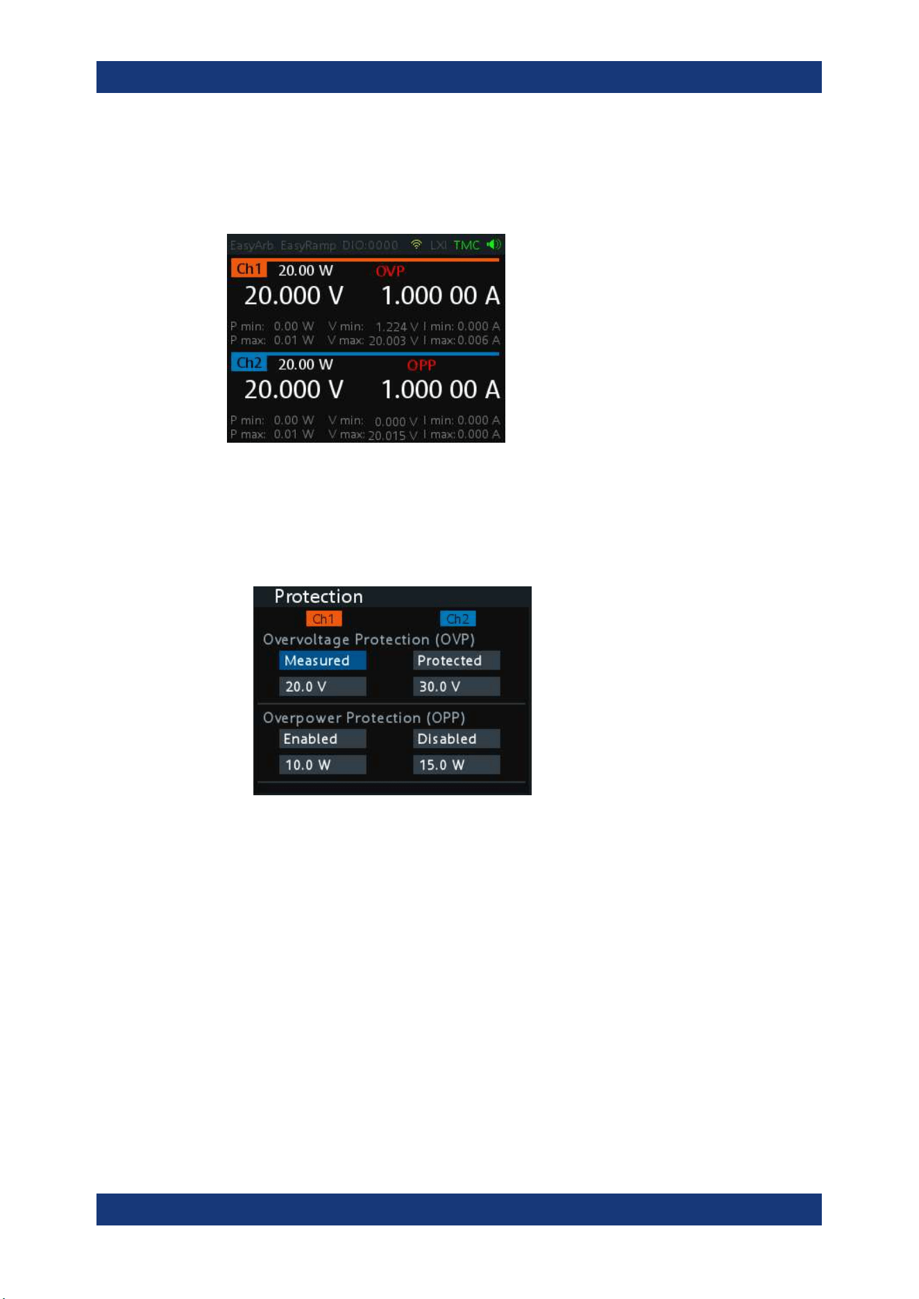
Instrument Functions
R&S
®
NGA100
49User Manual 5601.8919.02 ─ 05
If protection is tripped, a red flashing OVP or OPP indicator is displayed on the respec-
tive channel. See
Figure 6-8.
A beep is sounded if buzzer is enabled. See
Figure 6-21.
Figure 6-8: Indicator of OVP/OPP when tripped
1. Press [Menu] key.
2. Select "Output" > "Protection" menu item.
The R&S NGA100 displays the "Protection" dialog. See
Figure 6-9.
Figure 6-9: Protection dialog
3. Set the OVP mode for the desired channel.
The available options are as follows:
● "Measured": The output is switched off if the measured value exceeds the set
limit. Switching on the channels triggered the OVP if the condition remains.
● "Protected": The output is disabled if the setting exceeds the set limit.
● "Disabled": OVP is set to maximum value supported by hardware. See the R&S
NGA100 brochure for the instrument specification.
4. Set the desired voltage for OVP.
The R&S NGA100 turns off the respective channel when the measured voltage
exceeded the preset value.
5. Set the OPP mode for the desired channel.
Protection
Instrument Functions
R&S
®
NGA100
50User Manual 5601.8919.02 ─ 05
The available options are as follows:
● "Enabled": The channel is turned off if the measured power exceeds OPP
value.
● "Disabled": Depending on models, output power is limited to maximum value of
40 W (NGA101, NGA102) or 80 W (NGA141, NGA142).
6. Set the desired power for OPP.
The R&S NGA100 turns off the respective channel when the measured power
exceeded the preset value.
6.9 Digital Trigger I/O
Digital I/O Pins Voltage Rating
Do not exceed the maximum voltage rating of the Digital I/O pins (5.25 V max) when
supplying voltages to the pins.
R&S NGA-K103 (order number: 5601.8425.99) option is required for the Digital Trigger
I/O.
The four data lines of the digital I/O interface are mutually independent and can be
used as trigger input or trigger output separately. See
Figure 4-3.
●
Trigger input
The data lines of the digital I/O interface receive external trigger signal. The exter-
nal trigger signal triggers the selected channel (Ch 1, Ch 2) with the set response
when the trigger condition (Active High or Active Low) is met.
●
Trigger output
The data lines of the digital I/O interface output an "Active Low" or "Active High"
signal when the trigger condition of the selected channel is met.
Table 6-1: Trigger in parameters and conditions
Trigger in parameters Trigger conditions Description
Channel Ch 1, Ch 2 Target output channel selected for trigger
response.
Response Trigger Output On Level Selected channel [Output] is enabled when
the selected logic level is met.
Output Off Level Selected channel [Output] is disabled when
the selected logic level is met.
Output Toggle Pulse Selected channel [Output] is toggled when
the selected logic pulse is met.
Digital Trigger I/O
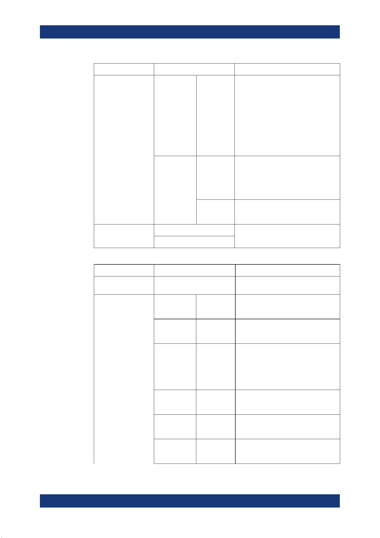
Instrument Functions
R&S
®
NGA100
51User Manual 5601.8919.02 ─ 05
Trigger in parameters Trigger conditions Description
Output Inhibit Level Selected channel [Output] is inhibited when
the selected logic level is met.
When the selected channel [Output] is put to
inhibit state, manual or remote operation on
selected channel [Output] is no longer possi-
ble .
To reverse the inhibit state, remove the
source of the trigger signal. You can either
disable the affected DIO interface or remove
the source from the affected DIO interface at
the rear panel.
Start EasyArb
(Only for Ch 1)
Level Activates the EasyArb function on channel 1
when the selected logic level is met. The
EasyArb is deactivated when the level
changes (i.e from active high to active low)
See Chapter 6.11.1, "EasyArb",
on page 54.
Pulse Activates the EasyArb function on channel 1
when the selected pulse is met. See Chap-
ter 6.11.1, "EasyArb", on page 54.
Logic Active High Set the logic level of the trigger in signal.
Active Low
Table 6-2: Trigger out parameters and conditions
Trigger out parameters Trigger conditions Description
Channel Ch 1, Ch 2 Output channel selected to monitor for trig-
ger condition.
Condition Trigger Output On
Output the selected logic level when the
[Output] is turned on at the selected chan-
nel.
Output Off
Output the selected logic level when the
[Output] is turned off at the selected chan-
nel.
Fuse Tripped
Output the selected logic level when a fuse
tripped event occurs on the selected chan-
nel.
See Chapter 6.6, "Activating Fuse",
on page 46 and Chapter 6.6.1, "Fuse Delay,
Fuse Linking", on page 47.
CC Mode
Output the selected logic level when the
selected channel operates in the CC mode.
See "CC mode" on page 39.
Voltage Level >= "set value" Output the selected logic level when the
voltage level of the selected channel is
greater or equal to the set level.
Current Level >= "set value" Output the selected logic level when the
current level of the selected channel is
greater or equal to the set level.
Digital Trigger I/O
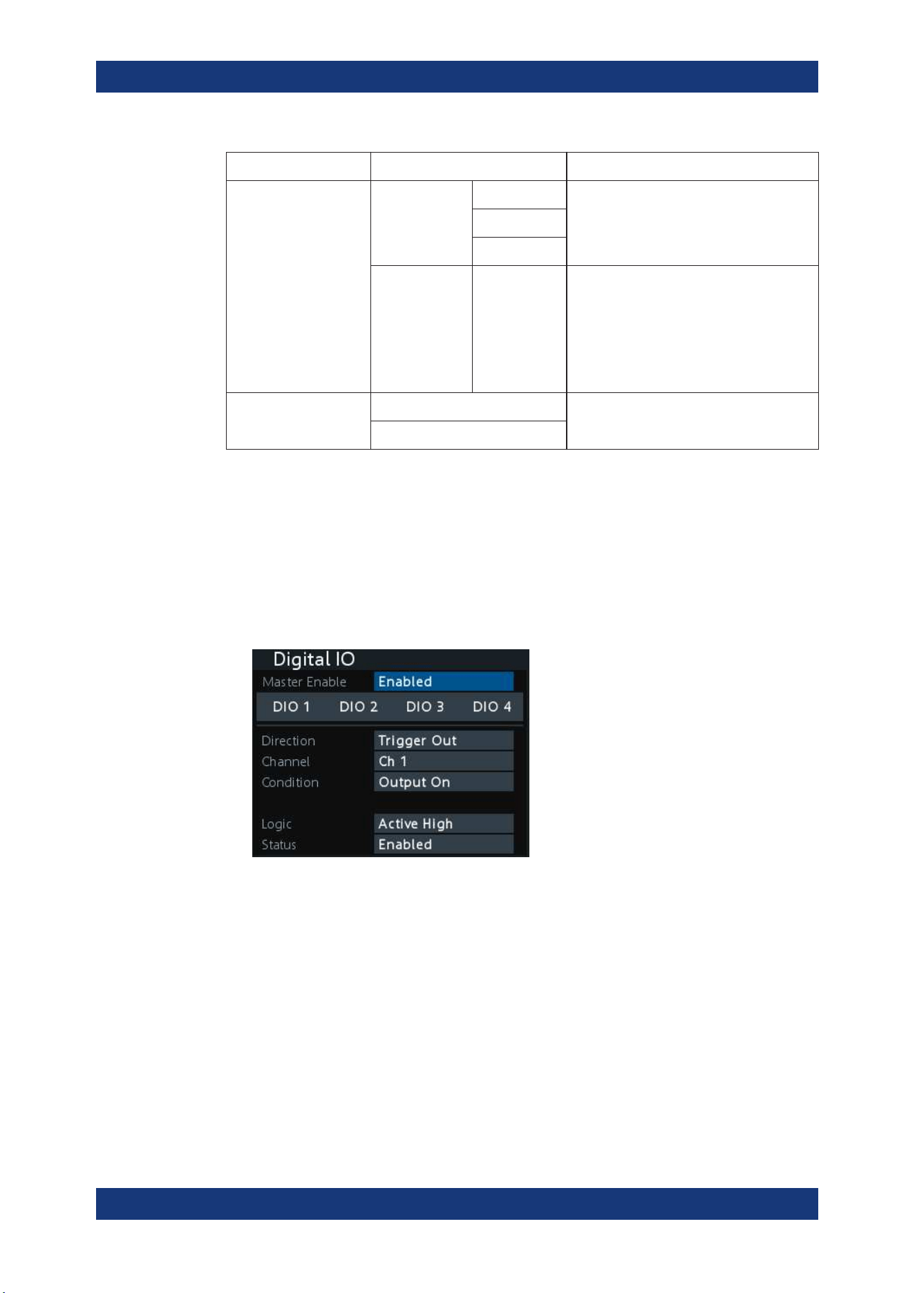
Instrument Functions
R&S
®
NGA100
52User Manual 5601.8919.02 ─ 05
Trigger out parameters Trigger conditions Description
Critical Event OVP Output the selected logic level when the
selected critical event (OVP, OPP, OTP)
occurs on the selected channel. See Chap-
ter 6.8, "Protection", on page 48.
OPP
OTP
EasyArb Active
Output the selected logic level when the
EasyArb function is running on channel 1.
See Chapter 6.11.1, "EasyArb",
on page 54.
Note: For a reliable DIO trigger output, the
EasyArb waveform needs to be at least 200
ms.
Logic Active High Set the logic level of the trigger out signal.
Active Low
To setup the DIO for usage, you have to enable the required DIO and "Master Enable"
parameters:
Note: After a recall function, the "Master Enable" is disabled, see
"Recall instrument
settings"
on page 59.
1. Press [Menu] key.
2. Select "Interface" > "Digital IO" menu item.
The R&S NGA100 displays the "Digital IO" dialog. See
Figure 6-10.
Figure 6-10: Digital IO dialog
3. Select the desired DIO interface.
4. Select "Trigger In" to accept external trigger signal or "Trigger Out" to output the
trigger signal.
5. Set the desired "Channel".
6. Select the desired trigger condition.
See
Table 6-1 and Table 6-2.
7. Set the desired "Logic" state.
8. Set the "Status" to "Enabled".
Digital Trigger I/O
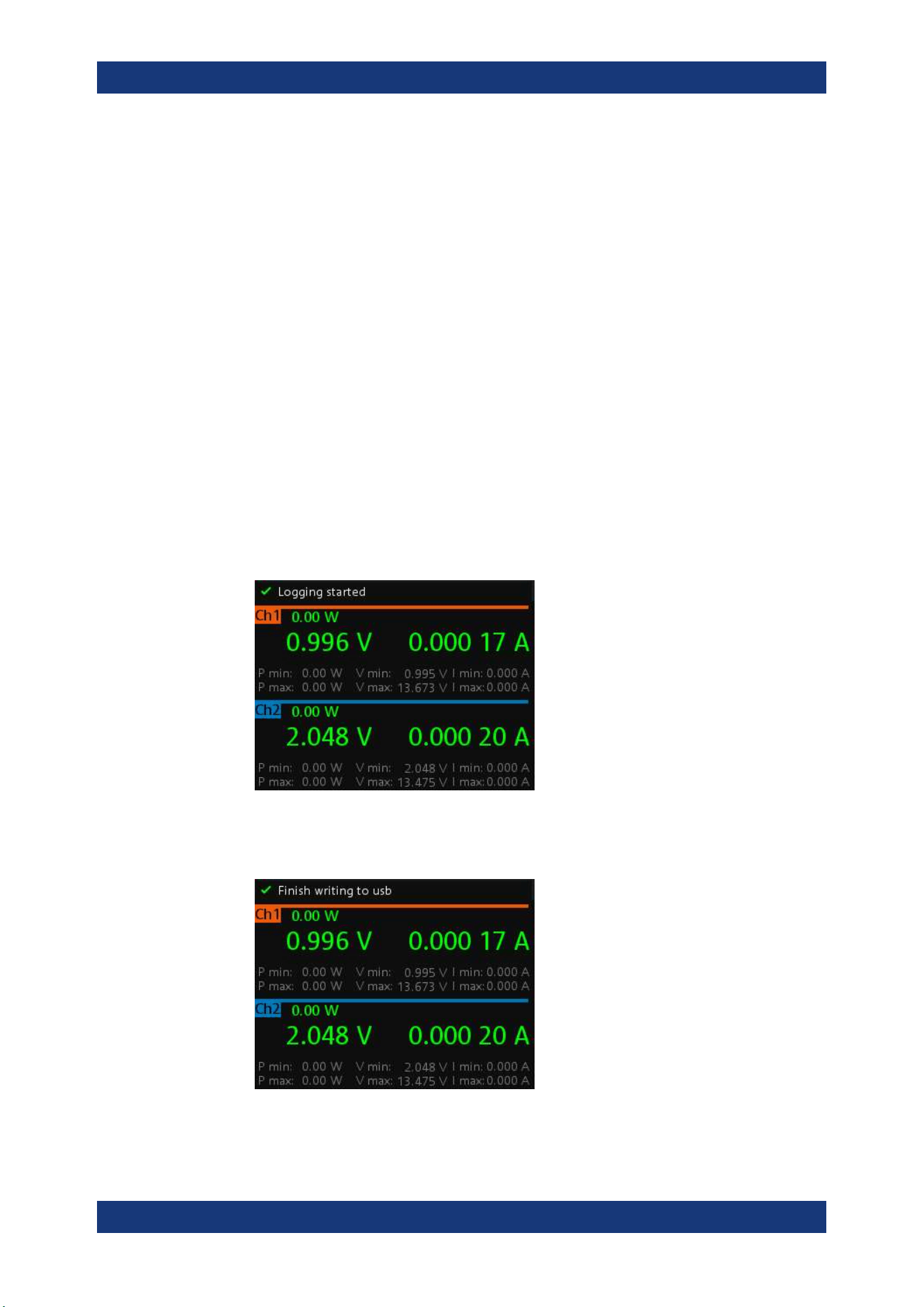
Instrument Functions
R&S
®
NGA100
53User Manual 5601.8919.02 ─ 05
The R&S NGA100 enabled the selected DIO interface and monitor or feedback the
trigger condition on the selected channel.
9. Set the "Master Enable" to "Enabled".
The "Master Enable" is the master DIO interface which activates or deactivates all
the DIO interfaces.
6.10 Data Logging
The data logging function provides the logging of data to external USB storage.
1. Attached a USB storage to the USB connector on the front panel.
2. Press [Log] key on the front panel.
The R&S NGA100 starts the data logging.
An indicator "Logging started" is displayed on the status bar, the [Log] key is also
illuminated when data logging starts.
The data is stored in the file named log-yyyyMMddTHHmmss.csv , e.g.
log-19701231T235501.csv. See
Figure 6-11.
3. Toggle the [Log] key to stop data logging.
The R&S NGA100 finishes the data logging.
An indicator "Finish writing to usb" is displayed on the status bar.
Data Logging
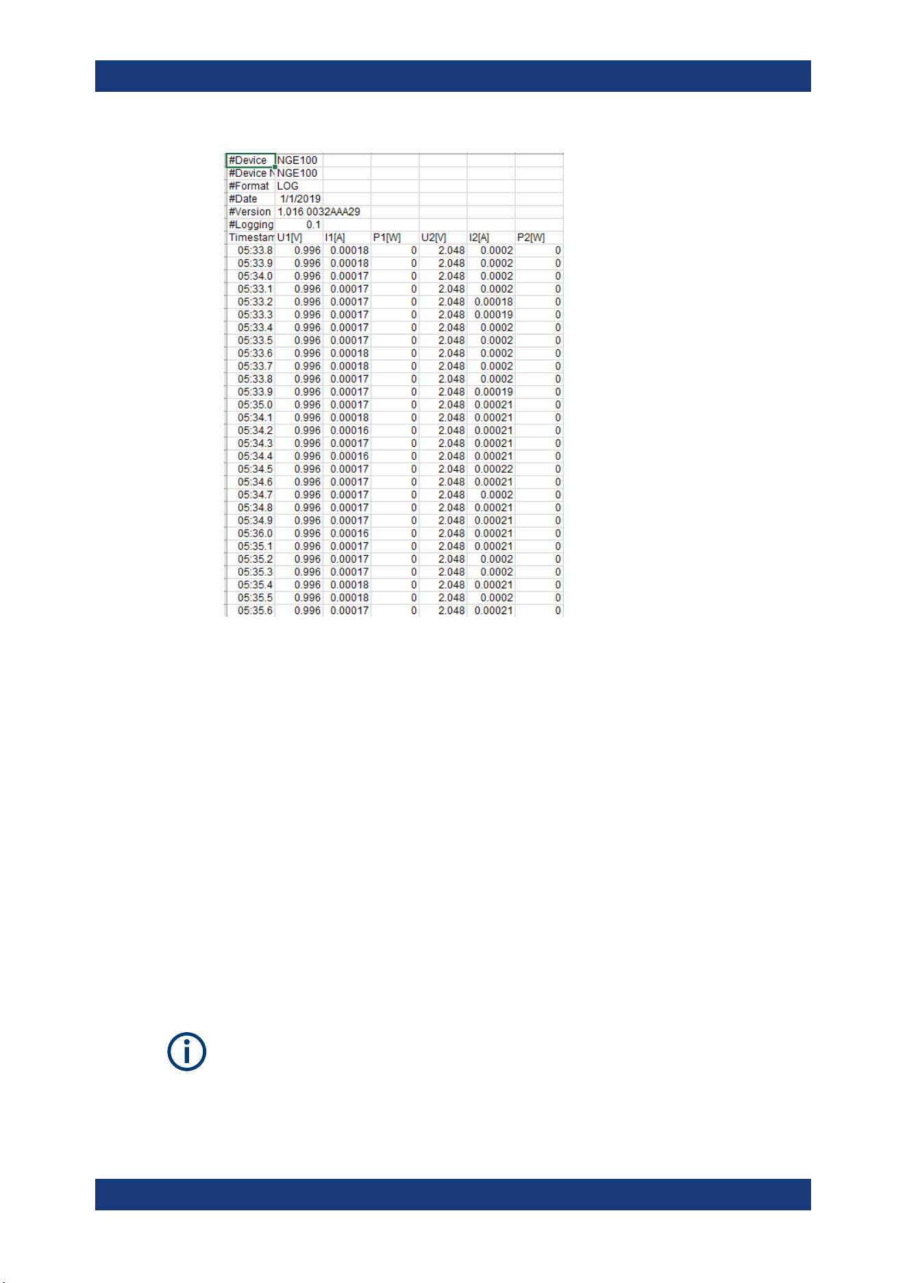
Instrument Functions
R&S
®
NGA100
54User Manual 5601.8919.02 ─ 05
Figure 6-11: Log data sample
6.11 Advanced Functions
The following chapters provide information about the EasyArb and EasyRamp menu
items found in the [Menu] key.
1. Press [Menu] key.
The R&S NGA100 displays the main menu of the instrument.
See
Chapter 5.2.3, "Menu Key", on page 34.
2. Select the "Output" menu item.
The R&S NGA100 displays the respective menu item dialog.
6.11.1 EasyArb
EasyArb function
The arbitrary function is available only in Ch 1.
See "Voltage, current settings" on page 40.
Advanced Functions
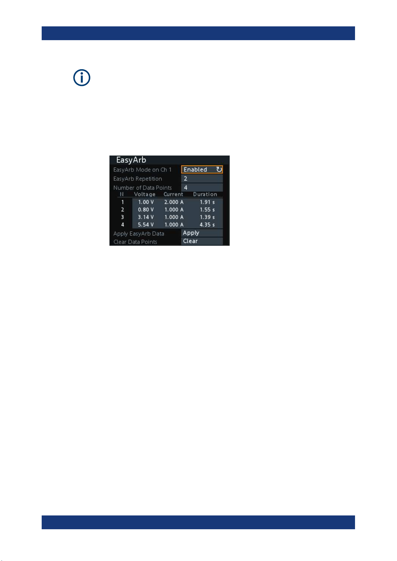
Instrument Functions
R&S
®
NGA100
55User Manual 5601.8919.02 ─ 05
LabVIEW driver
The arbitrary functions in LabVIEW driver rshmc804x do not support the EasyArb fea-
ture in the R&S NGA100.
The R&S NGA100 series allows you to generate freely programmable waveforms
which can be reproduced within the limits set by the instrument for voltage and current.
1. Select "EasyArb" menu item.
The R&S NGA100 displays the "EasyArb" dialog. See
Figure 6-12.
Figure 6-12: EasyArb dialog
2. Set "EasyArb Mode on Ch 1" to "Enabled".
The R&S NGA100 enabled the EasyArb function for Ch 1.
Note: If "EasyArb Mode" is set disabled, corresponding output state of Ch 1 is also
disabled.
3. Set the desired repetition cycle for the EasyArb function.
4. Set the desired data points for the EasyArb function.
The R&S NGA100 displays the number of EasyArb entry points in the EasyArb
table.
5. Configure the EasyArb table with the desired values for voltage, current and dura-
tion.
6. Select "Apply" to save the EasyArb settings.
The EasyArb data points are sent to Ch 1.
7. Select "Clear" to reset the EasyArb table values.
All the EasyArb data points are cleared from Ch 1.
See
Table 6-3.
8. Press [Menu] key to return to the Channel Display Area.
The [Enter] key is illuminated.
9. Press [Output] key to enable the R&S NGA100 output.
10. Press [Enter] key to start the EasyArb function.
11. Long press on the [Enter] key to stop the EasyArb function.
Advanced Functions
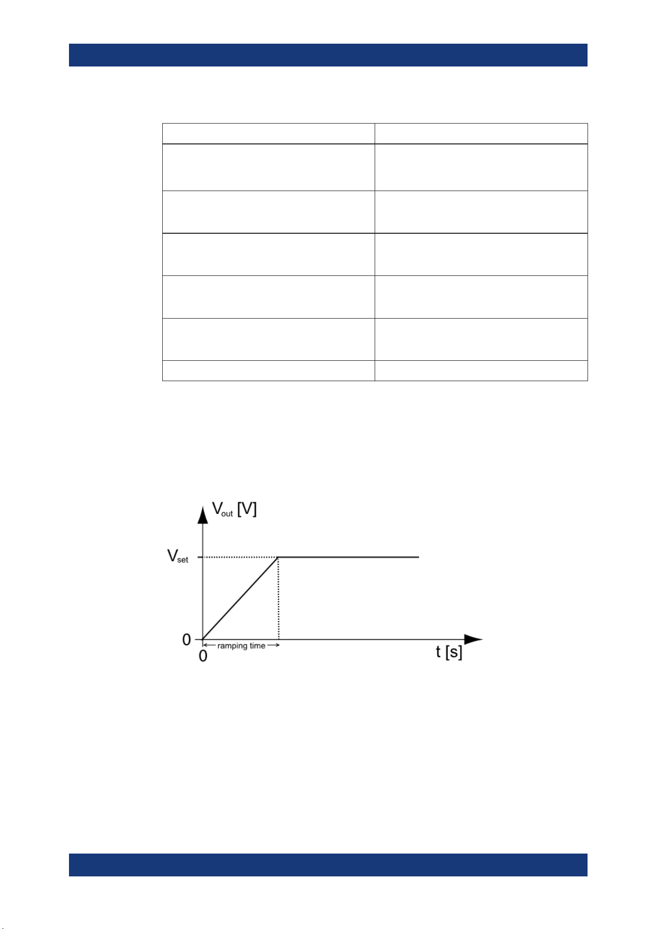
Instrument Functions
R&S
®
NGA100
56User Manual 5601.8919.02 ─ 05
Table 6-3: EasyArb input field
EasyArb input field Description
EasyArb mode Enable or disable the EasyArb function.
If enabled, the EasyArb function is activated in Ch 1.
See "EasyArb function" on page 54.
Data points Set the number of data points in the EasyArb table.
Each data point contains the settings for "Voltage",
"Current" and "Duration".
Repetition Set the number of times the waveform is output in
the EasyArb table. If this is set to "0", the waveform
is output continuously.
EasyArb table Configures the EasyArb data table. Use the arrow
keys to navigate the "Voltage", "Current" and "Dura-
tion" settings.
Clear Reset all the data points in the EasyArb table to
0.00 V, 1.000 A and 0.01 s for "Voltage", "Current"
and "Duration" respectively.
Apply Select "Apply" to save EasyArb configuration.
6.11.2 EasyRamp
With EasyRamp, the R&S NGA100 provides you the operating condition to output a
constant rise of the supply voltage. The output voltage can be increased continuously
within a 10 ms to 10 s timeframe. See
Figure 6-13.
Figure 6-13: Ramping voltage output
1. Select "EasyRamp" menu item.
The R&S NGA100 displays the "EasyRamp" dialog. See
Figure 6-14.
Advanced Functions
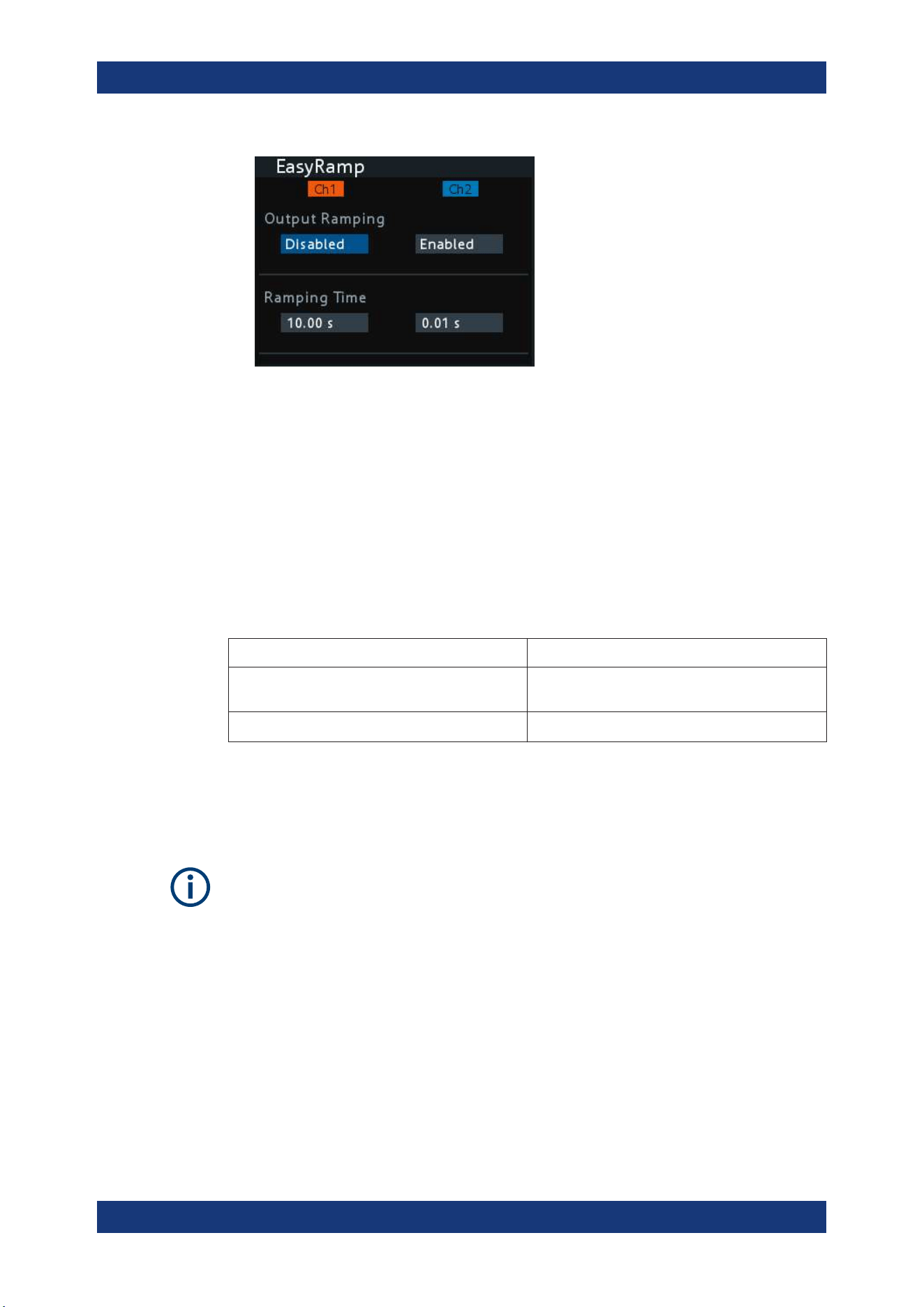
Instrument Functions
R&S
®
NGA100
57User Manual 5601.8919.02 ─ 05
Figure 6-14: EasyRamp dialog
2. Select the desired channel.
3. Set the selected channel to "Enabled".
The R&S NGA100 enabled the EasyRamp function for the selected channel.
Note: If selected channel is set disabled, corresponding output state of the selected
channel is also disabled.
4. Set the "Ramping Time" of the selected channel.
5. Press [Enter] key to confirm the settings.
Table 6-4: EasyRamp input field
EasyRamp input field Description
"Output Ramping" Enable or disable the EasyRamp function individu-
ally for each channel.
"Ramping Time" Duration taken for the voltage to rise to V
set
.
6.12 Store and Recall
Upon power-up, the instrument loads the stored setting from memory location M1 with
the exception on EasyArb parameters. Auto saved parameters are also applied during
startup.
The R&S NGA100 output state of all channels (Ch 1, Ch 2) is disabled when the recall
function is activated.
Store and Recall
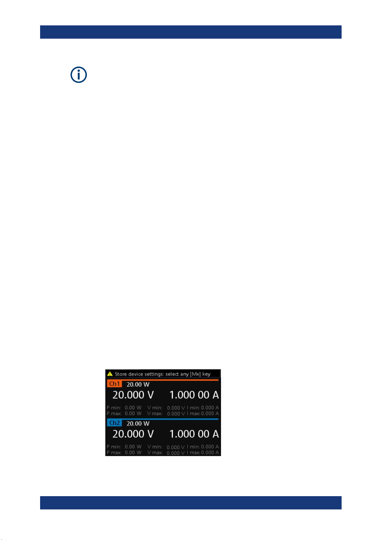
Instrument Functions
R&S
®
NGA100
58User Manual 5601.8919.02 ─ 05
Auto save instrument settings
Auto save of instrument settings are applied when any of the following parameters
changed:
●
General instrument settings
●
USB connection mode
●
WLAN settings
– "Module"
– "SSID"
– "Password"
●
Ethernet
The instrument settings can be stored or recalled from memory locations M1 to M5.
The following instrument settings are stored or recalled in the memory location:
●
Fuse settings
●
Protection settings
●
EasyRamp settings
●
Set voltage level
●
Set current level
●
1
EasyArb settings
●
1
Digital IO settings
1
The EasyArb or DIO settings can only be saved in the respective dialog environment
and all other above instrument settings are not saved when a store function is made.
When a recall function is made on the same stored memory location, only the EasyArb
or DIO settings are recalled.
Store instrument settings
1. Long press [Store Recall] key to store instrument settings.
The R&S NGA100 displays a message in the status bar "Store device settings:
select any [Mx] key".
Store and Recall
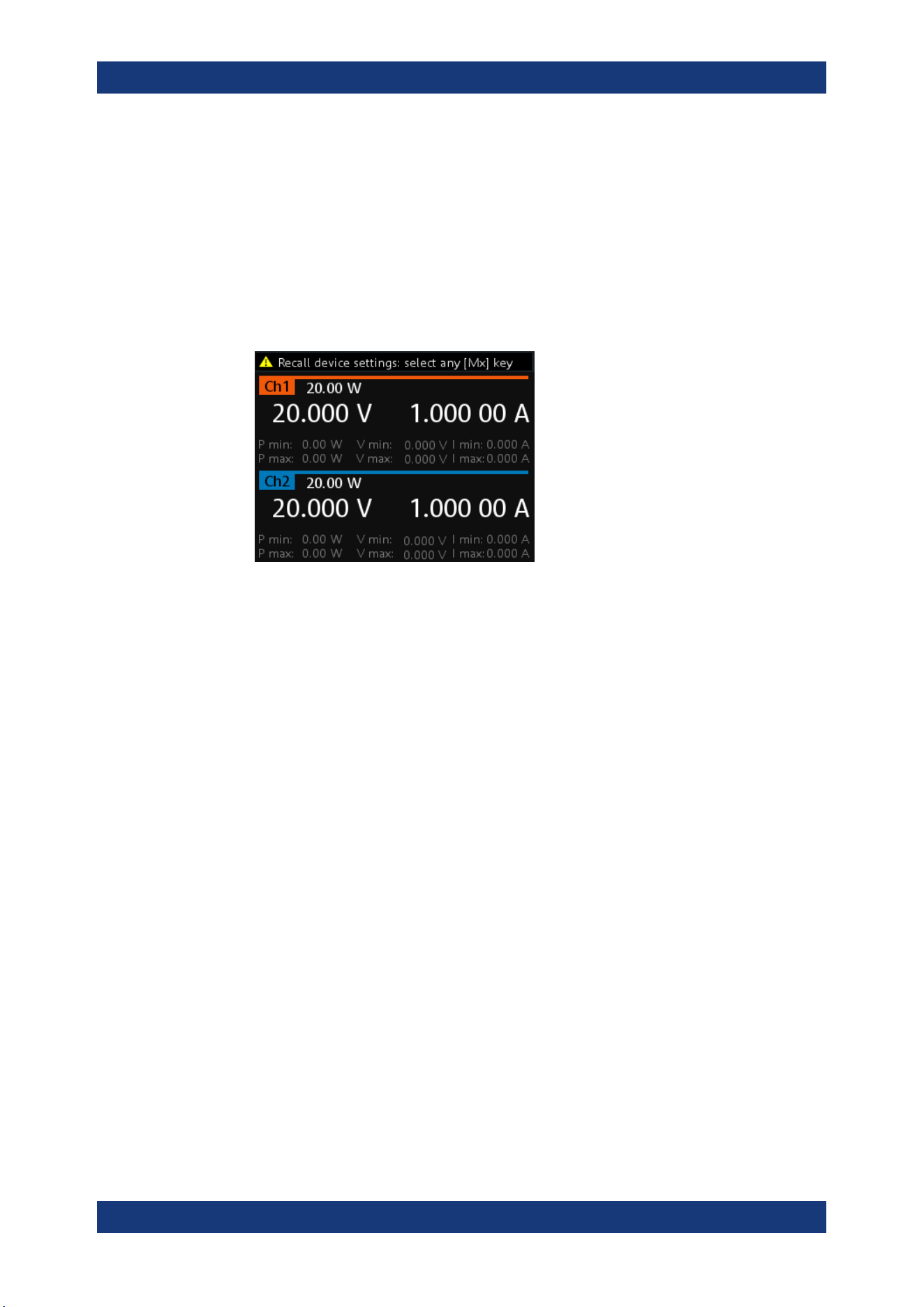
Instrument Functions
R&S
®
NGA100
59User Manual 5601.8919.02 ─ 05
2. Press any of the memory keys ([M1],[M2], [M3], [M4], [M5]) to store the instrument
settings.
The R&S NGA100 stores the instruments settings in the selected memory location.
Recall instrument settings
1. Press [Store Recall] key to recall instrument settings.
The R&S NGA100 displays a message in the status bar "Recall device settings:
select any [Mx] key".
2. Press any of the memory keys ([M1],[M2], [M3], [M4], [M5]) to recall the instrument
settings.
The R&S NGA100 recalls the instruments settings from the selected memory loca-
tion.
6.13 Interfaces and Protocols
There are various of ways how the R&S NGA100 can be remotely accessed and con-
trolled.
1. Press [Menu] key.
The R&S NGA100 displays the main menu of the instrument.
See Chapter 5.2.3, "Menu Key", on page 34.
2. Select "Interface" menu item to configure the required interface.
The R&S NGA100 displays the available interface options.
6.13.1 Network Connection
There are two methods to establish a local area network (LAN) connection with the
R&S NGA100 for remote control operation.
●
LAN
●
Wireless LAN
Interfaces and Protocols
Instrument Functions
R&S
®
NGA100
60User Manual 5601.8919.02 ─ 05
6.13.1.1 LAN Connection
The R&S NGA100 is equipped with a network interface and can be connected to an
Ethernet LAN (local area network). A LAN connection is necessary for remote control
of the instrument, and for access from a computer using a web browser.
Risk of network failure
Before connecting the instrument to the network or configuring the network, consult
your network administrator. Errors may affect the entire network.
To establish a network connection, connect a commercial RJ-45 cable to the LAN port
of the instrument and to a PC or network switch.
Depending on the network capacities, the TCP/IP address information for the instru-
ment can be obtained in different ways.
●
If the network supports dynamic TCP/IP configuration using the Dynamic Host
Configuration Protocol (DHCP), and a DHCP server is available, all address infor-
mation can be assigned automatically.
●
Otherwise, the address must be set manually. Automatic Private IP Addressing
(APIPA) is not supported.
By default, the instrument is configured to use dynamic TCP/IP configuration and
obtain all address information automatically. This means that it is safe to establish a
physical connection to the LAN without any previous instrument configuration.
Risk of network errors
Connection errors can affect the entire network. If your network does not support
DHCP, or if you choose to disable dynamic TCP/IP configuration, you must assign valid
address information before connecting the instrument to the LAN. Contact your net-
work administrator to obtain a valid IP address.
1. Connect a LAN cable to the LAN port.
2. Configure the connection settings manually or have the network configure the set-
tings for you via menu. By default, automatic configuration is set in the instrument.
For manual configuration, configure the settings as follows:
Interfaces and Protocols
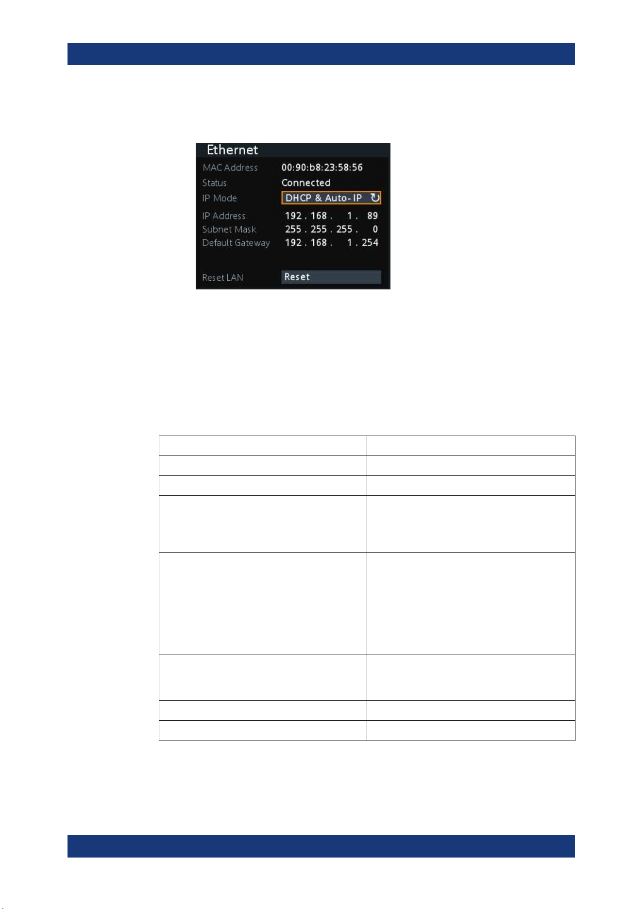
Instrument Functions
R&S
®
NGA100
61User Manual 5601.8919.02 ─ 05
a) Select "Ethernet" menu item.
The R&S NGA100 displays the "Ethernet" dialog.
Figure 6-15: Ethernet dialog
b) Select "DHCP & Auto-IP" for "IP Mode".
c) Enter the "IP Address".
d) Enter the "Subnet Mask".
e) Enter the "Default Gateway".
f) Select "Apply" to complete the configuration.
g) Press [Menu] key to exit the dialog.
Table 6-5: Ethernet input field
Ethernet input field Description
"MAC Address" Shows the MAC address of this instrument.
"Status" Shows if the connection is up or down.
"IP Mode" "Static & Manual": Manually configure an IP address
for the instrument.
"DHCP & Auto-IP": Automatically assign an IP
address to the instrument.
"IP Address" Address used in communication with the network.
Manually configure this field if IP mode set to "Static
& Manual".
"Subnet Mask" Secondary address used in communication with the
network.
Manually configure this field if IP mode set to "Static
& Manual".
"Default Gateway" Gateway address to connect to the network.
Manually configure this field if IP mode set to "Static
& Manual".
"Reset LAN" Restores the LAN settings to factory default.
"Apply" Apply static IP settings.
Interfaces and Protocols
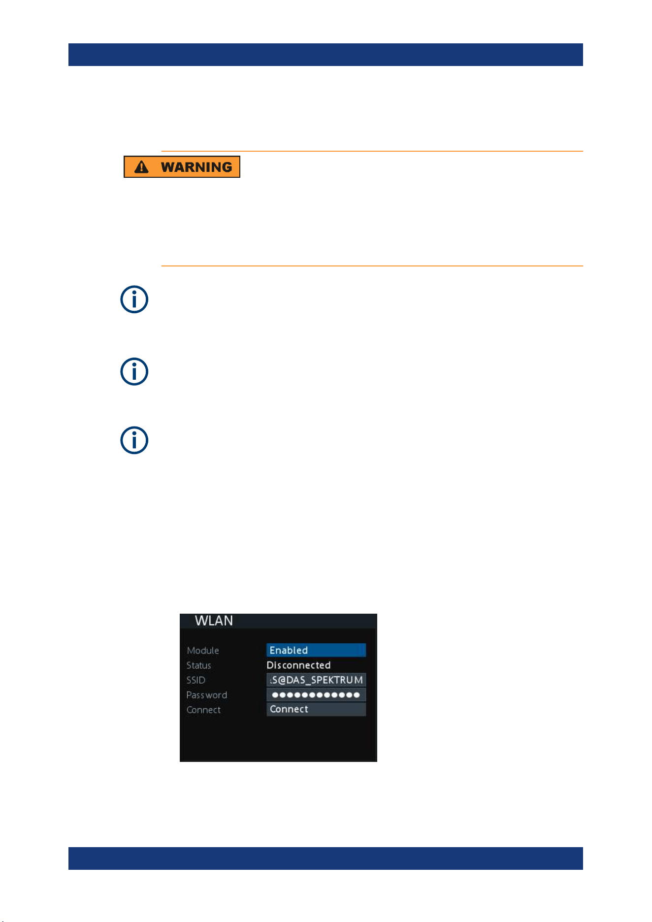
Instrument Functions
R&S
®
NGA100
62User Manual 5601.8919.02 ─ 05
6.13.1.2 Wireless LAN Connection
Risk of RF exposure
When WLAN is active, a minimum separation distance of 20 cm from front panel of the
instrument must be observed at all times.
When WLAN is active, no operation of antenna or transmitter should be co-located with
the instrument.
Wi-Fi transmitter performance
Frequency range: 2412 MHz to 2484 MHz
18.9 dBM (802.11g, 6Mbps)
Instrument option
R&S NGA-K102 (order number: 5601.8419.99) option is required to connect the R&S
NGA100 to a network via WLAN connection.
WLAN connection
The LAN connection has a higher priority over WLAN.
If LAN is connected, the WLAN connection will be disconnected. When LAN is discon-
nected, WLAN will reconnect automatically.
An alterative to connection in local area network is wireless LAN connection. With the
presence of an authenticated Wi-Fi signal, the R&S NGA100 automatically connects to
a network and navigation can be made via the web browser according to the WLAN
IEEE 802.11 b/g/n standards.
1. Select "WLAN" menu item.
The R&S NGA100 displays the "WLAN" dialog.
Figure 6-16: WLAN dialog
Interfaces and Protocols
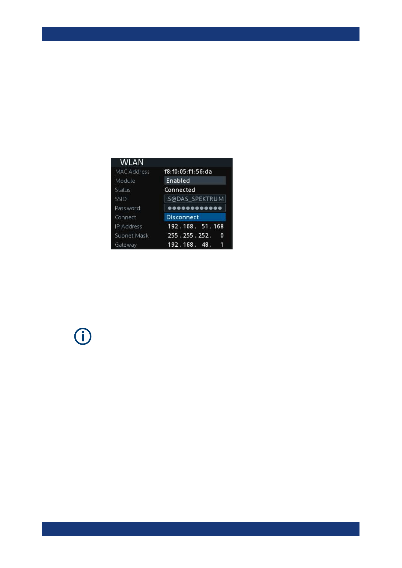
Instrument Functions
R&S
®
NGA100
63User Manual 5601.8919.02 ─ 05
2. Select "Enabled" for "Module".
3. Set the "SSID"
SSID - Service Set Identifier, a unique ID used for naming wireless network.
4. Set the associated password for the "SSID".
5. Select the "Connect" button.
If connection is successful, the "Status" shows "Connected". See Figure 6-17.
When the connection is alive, the WLAN icon turns green on the status bar. See
"Device status bar" on page 28.
Figure 6-17: WLAN connected
6. To disconnect, select "Disconnect" in the WLAN dialog.
6.13.2 USB Connection
Change of USB class
If a change in "USB Class" is detected (i.e. from "TMC" to "VCP" or vice versa), the
rebooting of instrument is necessary to load the correct USB driver.
Alternatively, connect a USB cable to the USB port and PC for a USB connection. The
R&S NGA100 supports USB TMC and USB VCP connection.
1. Select "USB" menu item.
The R&S NGA100 displays the "USB" dialog.
Interfaces and Protocols
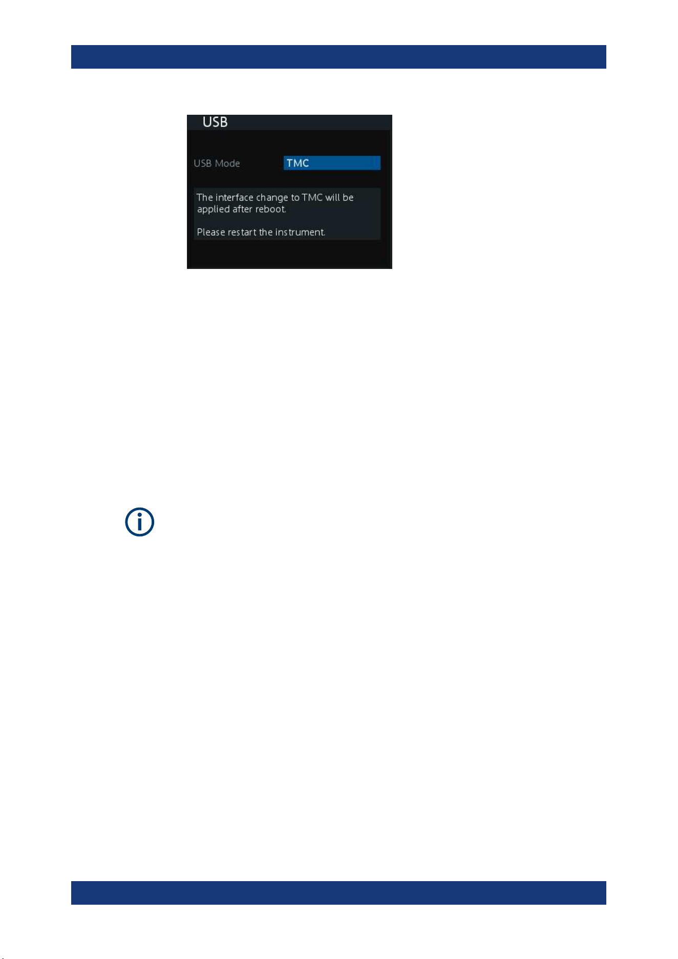
Instrument Functions
R&S
®
NGA100
64User Manual 5601.8919.02 ─ 05
Figure 6-18: USB dialog
2. Set the desired "USB Mode".
●
"VCP": USB virtual COM port
● "TMC": USB Test & Measurement class
3. Press [Enter] key to confirm the settings.
The R&S NGA100 displays message to prompt the user to restart the instrument to
apply the changes.
4. Restart the R&S NGA100 to apply changes.
6.13.2.1 USB VCP
The following requirements for USB-VCP driver installation are necessary:
●
A PC with operating system Windows XP, VISTA, Windows 7 or Windows 8 (32Bit
or 64Bit).
●
Administrator rights are necessary for the installation of the driver.
The USB virtual COM port (USB-VCP) is a software interface that allows the communi-
cation to the R&S NGA100 using any terminal program (e.g. HMExplorer) via SCPI
commands once the corresponding Windows drivers have been installed. The actual
USB-VCP driver and software HMExplorer can be downloaded for free from the prod-
uct homepage (
http://www.rohde-schwarz.com/product/nga100).
If a connection between PC and the instrument has been established and no NGA100
USB-VCP driver is installed, the PC operating system displays a "Found New Hard-
ware" wizard. In this case, the NGA100 USB-VCP driver must be installed.
The HMExplorer window application provides the R&S NGA100 a terminal function and
also the option to create screenshots and editor function to create the EasyArb table.
For more information of the driver installation and HMExplorer window application, see
the installation guide of the driver file and the internal HMExplorer help.
Interfaces and Protocols

Instrument Functions
R&S
®
NGA100
65User Manual 5601.8919.02 ─ 05
6.13.2.2 USB TMC
The USB Test & Measurement class (USB-TMC) is a protocol that allows GPIB-like
communication via USB interfaces and is a separate instrument class of the USB spec-
ification. The USB-TMC protocol supports service queries, triggers, and other GPIB-
specific instructions.
VISA drivers are installed and that it can be used directly in the corresponding environ-
ments. The driver is included in the NI-VISA package and can be downloaded at
http://
www.ni.com/downloads/ni-drivers/
.
A major benefit of the USB TMC class is that by sampling specific registers the control-
ling software can determine if commands have been terminated and if they have been
processed correctly. With USB-VCP, communication with instrument requires analysis
and polling mechanisms within the controlling software which may significantly strain
the interface of the measurement instruments. The TMC status registers solve this
problem with the USB TMC in the same manner as in the case with the GPIB interface
for the hardware via the corresponding control lines.
HMExplorer
The window application supports the communication via LAN, USB VCP and WLAN
only.
For more information of the VISA driver installation, see the installation guide of the
VISA driver file.
Once the driver is installed, the "USB Test and Measurement Device (IVI)" is displayed
in the Windows "Device Manager" dialog, see
Figure 6-19.
Interfaces and Protocols
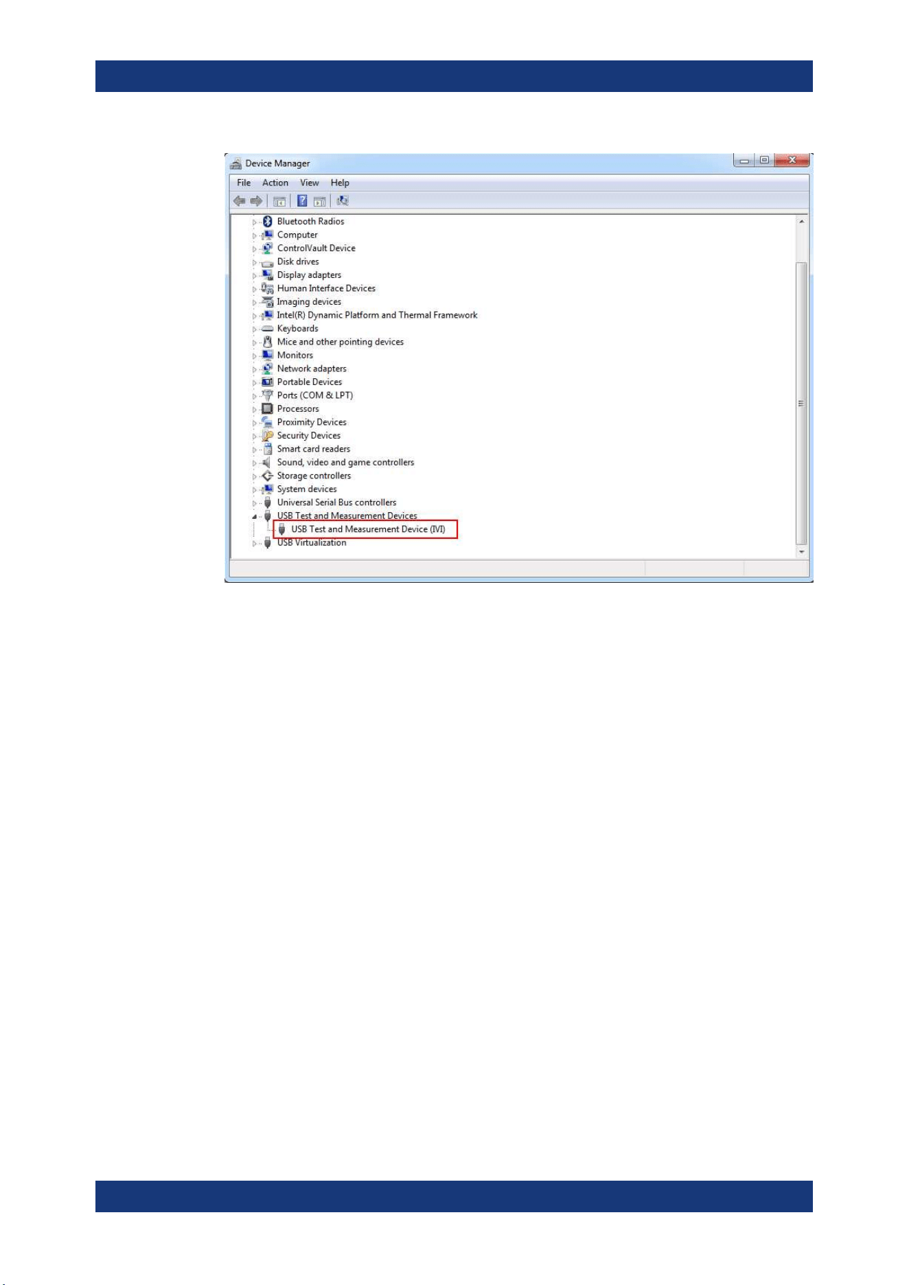
Instrument Functions
R&S
®
NGA100
66User Manual 5601.8919.02 ─ 05
Figure 6-19: Device manager
6.13.3 SCPI
SCPI (Standard Commands for Programmable Instruments) commands - messages -
are used for remote control. Commands that are not taken from the SCPI standard fol-
low the SCPI syntax rules. The instrument supports the SCPI version 1999. The SCPI
standard is based on standard IEEE 488.2 and aims at the standardization of device-
specific commands, error handling and the status registers. The tutorial "Automatic
Measurement Control" - A tutorial on SCPI and IEEE 488.2" from John M. Pieper (R&S
order number 0002.3536.00) offers detailed information on concepts and definitions of
SCPI.
The requirements that the SCPI standard places on command syntax, error handling
and configuration of the status registers are explained in detail in the following sec-
tions. For more information, see
Chapter 7, "Remote Control Commands",
on page 76 and Chapter A, "Additional Basics on Remote Control", on page 113.
6.13.4 VISA
VISA is a standardized software interface library providing input and output functions to
communicate with instruments. The I/O channel (LAN or USB) is selected at initializa-
tion time by means of a channel-specific resource string. For more information about
VISA, refer to its user documentation.
Interfaces and Protocols

Instrument Functions
R&S
®
NGA100
67User Manual 5601.8919.02 ─ 05
6.13.5 Setting Up Remote Control Connection
USB
The following shows the resource string format used when setting up a remote connec-
tion via the USB interface:
●
USB TMC
USB0::0x0AAD::
0x0197::5601.8002<device_variant>-<device_serial_number>::
INSTR where k02 is used for NGA101 device, k03 is used for NGA141 device, k04
is used for NGA102 device, k05 is used for NGA142 device. (e.g.
USB0::0x0AAD::0x0197::5601.8002k05-900211::INSTR)
●
USB VCP
ASRL<COM>::INSTR, where "COM" refers to the COM port number shown on the
controlling PC. (e.g. ASRL15::INSTR)
LAN/WLAN
See
Chapter 6.13.1, "Network Connection", on page 59 for configuring the LAN and
WLAN parameters.
To set up the connection the IP address of the instrument is required. It is part of the
resource string used by the program to identify and control the instrument. The
resource string has the form:
TCPIP::‹IP_address›::INST
Example: If the instrument has the IP address 192.1.2.3; the valid resource string is:
TCPIP::192.1.2.3::INST
High-Speed LAN Instrument Protocol (HiSLIP) is a TCP/IP-based protocol for remote
instrument control of LAN-based test and measurement instruments. It was specified
by the IVI Foundation and is intended to replace the older VXI-11 protocol. To start
remote control session with HiSLIP, the valid resource string is:
TCPIP::192.1.2.3::HISLIP
The end character must be set to line feed (LF).
Remote
Press [Remote] key to unlock the instrument from the remote control mode. In the
remotes mode, all front panel keys on the instrument are disabled and the [Remote]
key is illuminated. To switch back to the local mode, press [Remote] key to release the
remote control mode.
Interfaces and Protocols
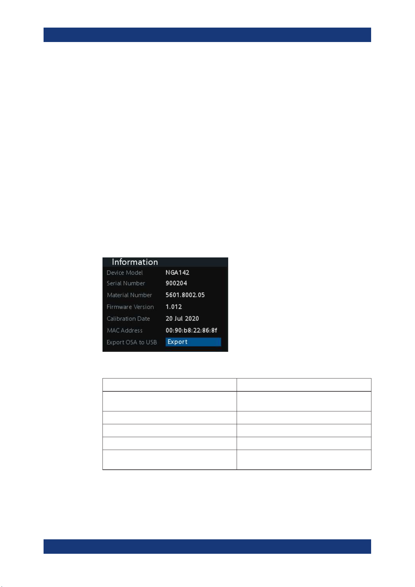
Instrument Functions
R&S
®
NGA100
68User Manual 5601.8919.02 ─ 05
6.14 General Instrument Settings
The following chapters provide the general instrument information and utilities services
in R&S NGA100.
1. Press [Menu] key.
The R&S NGA100 displays the main menu of the instrument.
See Chapter 5.2.3, "Menu Key", on page 34.
2. Select "Device" menu item to configure the required instrument settings.
3. Select "Utilities" menu item to configure the utilities services.
6.14.1 Instrument Information
The "Information" dialog provides the general instrument information of R&S NGA100.
► Select "Information" menu item.
The R&S NGA100 displays the "Information" dialog. See
Figure 6-20.
Figure 6-20: Information dialog
Device information Description
"Device Model" Model of the instrument, i.e. NGA101, NGA102,
NGA141 or NGA 142.
"Serial Number" Unique identification number for the instrument.
"Material Number" Instrument orderable part number.
"Firmware Version" Software version that is installed in the instrument.
"Calibration Date" The last registered date when calibration was car-
ried out on the instrument.
General Instrument Settings
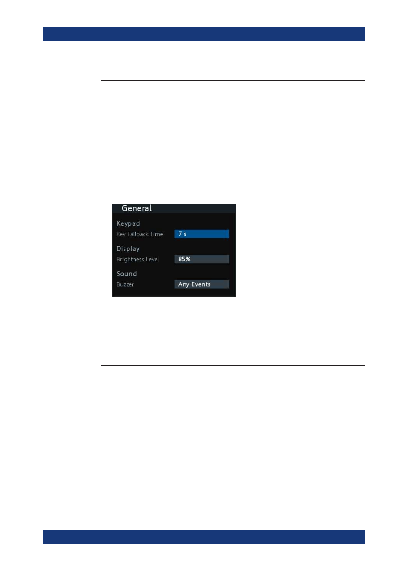
Instrument Functions
R&S
®
NGA100
69User Manual 5601.8919.02 ─ 05
Device information Description
"MAC Address" MAC address of the network interface.
"Export OSA to USB" The open-source acknowledgment (OSA) of the
R&S NGA100 can be exported to USB stick for ref-
erence.
6.14.2 General Instrument Settings
General instrument settings such as keypad fallback time, screen display brightness
and buzzer setting are provided.
► Select "General" menu item.
The R&S NGA100 displays the "General" dialog. See Figure 6-21.
Figure 6-21: General dialog
General instrument settings Description
Keypad Selects the wait time before the instrument automat-
ically leaves the editing mode. Select "Off" to dis-
able the automatic switching back.
Display Selects the specific screen intensity to control the
screen brightness. Setting is applied immediately.
Sound Selects the event where sound is generated.
●
"Fault Events": Sounds on faulty events only
●
"Any Events": Sounds on faulty events and key
press events
●
Disabled: No sound is generated
6.14.3 Managing Options
Options are enabled by entering a registered license key code.
You may choose to install from an XML file on USB or by manually entering the key
code.
► Select "License" menu item.
General Instrument Settings

Instrument Functions
R&S
®
NGA100
70User Manual 5601.8919.02 ─ 05
The R&S NGA100 displays the "License" dialog. See Figure 6-22.
Figure 6-22: License dialog
To install from an XML file, proceed as follows:
1. Copy the XML file containing the registered key code into the USB flash drive.
2. Connect the USB flash drive to the USB port of the instrument.
3. Select "Install".
If the installation is successful, the option is marked as "Installed" under "Installa-
tion Status".
To manually enter the key code, proceed as follows:
1. Press [Enter] key to invoke the
On-screen Keyboard.
2. Enter the key code (30-digit number) of the option in the entry box.
3. Select "Install".
If the correct key code is entered, the option is marked as "Installed".
If an invalid key code is entered, an error message is displayed. Re-enter the cor-
rect key code.
6.14.4 Reset Instrument
This function resets the instrument to factory default settings.
The following settings are reset to default:
► Select "Reset" menu item.
The R&S NGA100 displays the "Reset" dialog. See Figure 6-23 .
General Instrument Settings
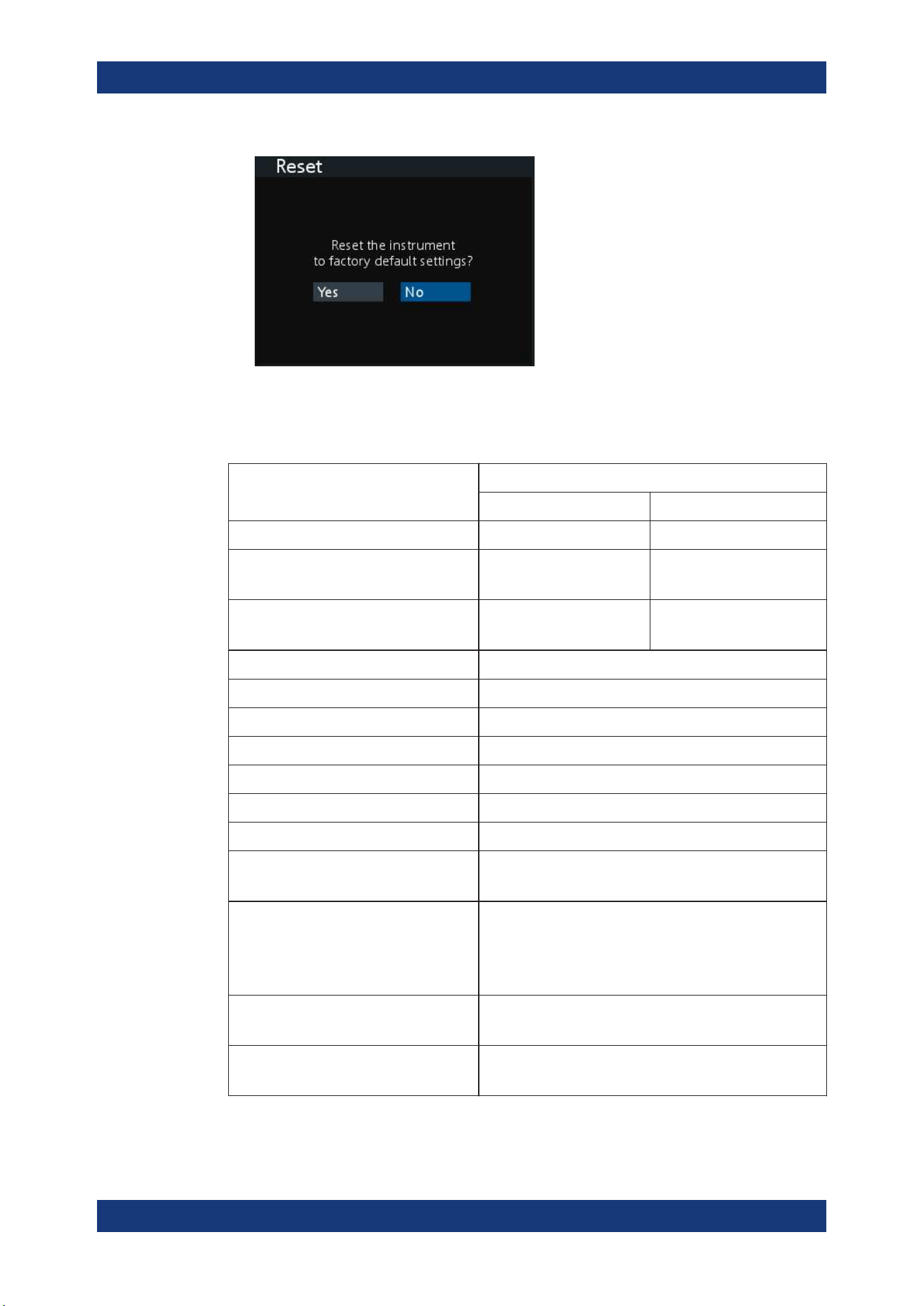
Instrument Functions
R&S
®
NGA100
71User Manual 5601.8919.02 ─ 05
Figure 6-23: Reset dialog
The following parameters are reset to default:
Parameters Default settings
NGA 101, NGA 102 NGA 141, NGA 142
Voltage, current 6.000 V, 6.050 20.00 V, 2.030 A
Overvoltage Protection (OVP)
Status, OVP level
Measured, 36.0 V Measured, 102.0 V
Overpower Protection (OPP)
Status, OPP level
Enabled, 41.0 W Enabled, 41.0 W
Output status Off
Channel history information 0
Channel fusion "Connection Mode" Off
"Current Measurement Range" High
"Fuse Delay", "Fuse Linking" 0.00 s, Disabled
"Remote Sense" Disabled
"EasyArb Mode on Ch 1" Disabled
EasyRamp
"Output Ramping", "Ramping Time"
Disabled, 0.01 s
Digital IO
"Master Enabled"
"Direction", "Channel", "Condition"
"Logic", "Status"
Disabled
"Trigger Out", "Ch 1", "Output On"
"Active High", "Disabled"
WLAN
SSID, Password
"SSID", "......"
General
"Key Fallback Time", "Brightness Level"
7 s, 85%
General Instrument Settings
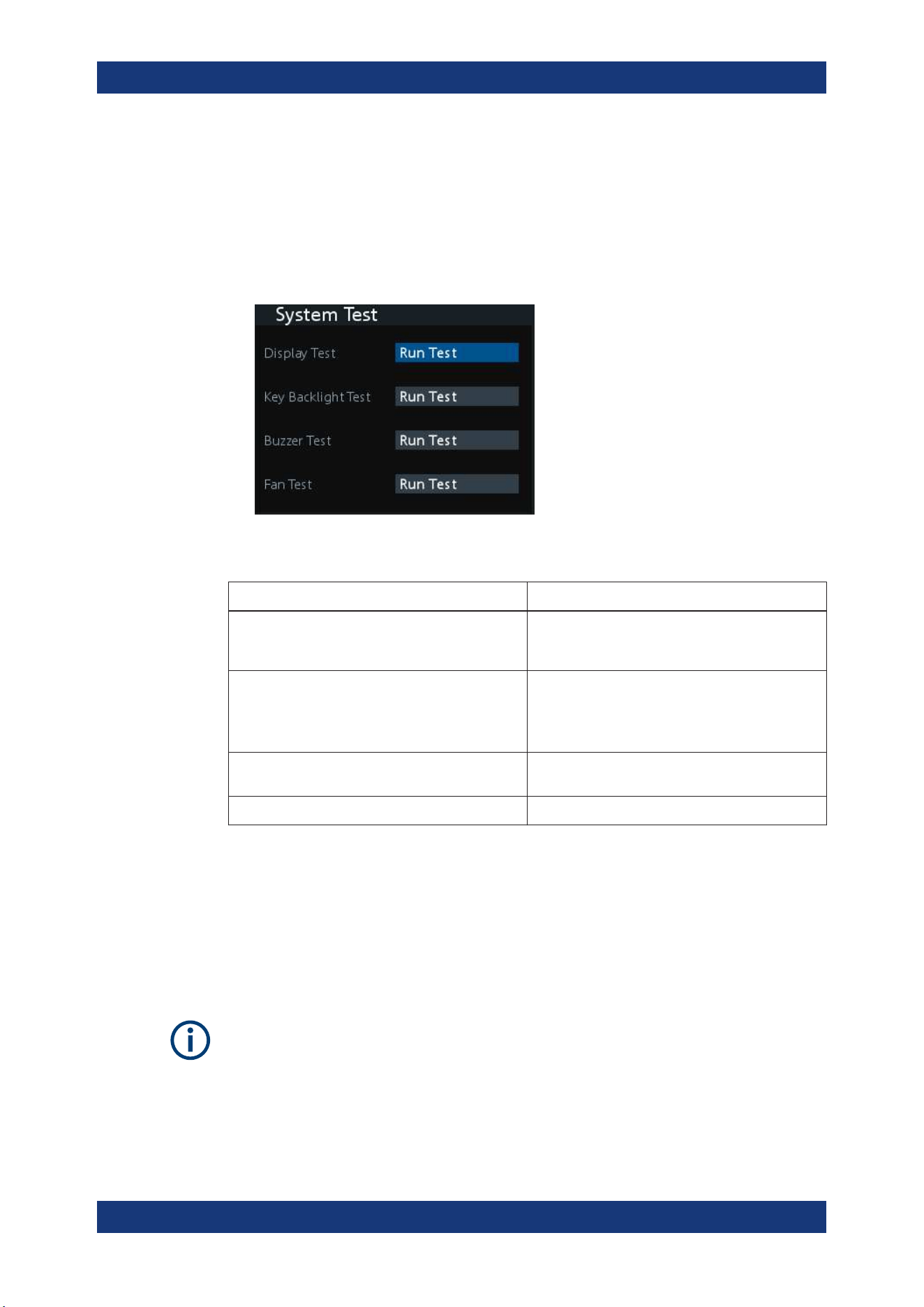
Instrument Functions
R&S
®
NGA100
72User Manual 5601.8919.02 ─ 05
6.14.5 System Test
This function provides a system test to check the instrument working conditions for
screen color display, key backlight, beeper and cooling fan.
► Select "System Test" menu item.
The R&S NGA100 displays the "System Test" dialog. See Figure 6-24.
Figure 6-24: System test dialog
System test Description
"Display Test" Test that the display is working. RGB and a list of
supported colors should appear on the screen dur-
ing the test.
"Key Backlight Test" Test that the key backlight is working.
During the test, all keys on the front panel illuminate
except ([M1], [M2], [M3], [M4], [M5]) and [Store
Recall].
"Beeper Test" Test that the instrument sound is working. Three
beep sounds should be heard during the test.
" Fan Test" Test that the cooling fan is working.
6.14.6 Updating the Firmware
The latest firmware file can be found from the product homepage http://www.rohde-
schwarz.com/product/nga100
.
For firmware update using SCPI command, see
"Firmware update via SCPI command"
on page 73.
Do not power off or operate the instrument during a firmware update.
Do not rename the firmware filename.
1. Download the firmware file from the product homepage.
2. Copy the firmware to the root directory of a USB flash drive.
General Instrument Settings
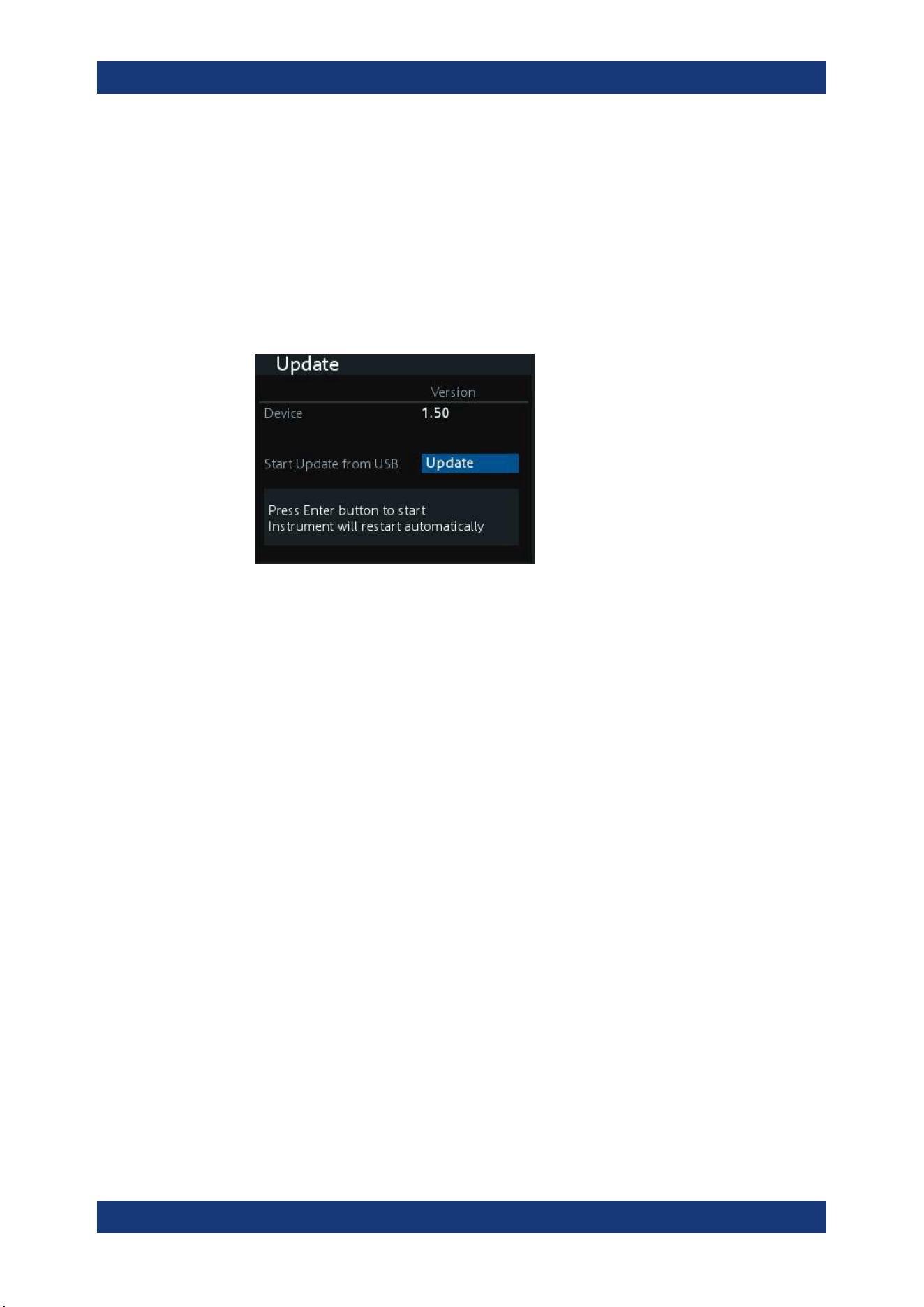
Instrument Functions
R&S
®
NGA100
73User Manual 5601.8919.02 ─ 05
3. Connect the USB flash drive to the USB port of the instrument and wait for ten sec-
onds.
4. Press [Menu] key.
The R&S NGA100 displays the main menu of the instrument. See Chapter 5.2.3,
"Menu Key", on page 34.
5. Select "Utilities" > "Update" menu item.
If firmware file is found, the R&S NGA100 displays the "Update" dialog. See Fig-
ure 6-25.
Figure 6-25: Update dialog
6. Press [Enter] key to start firmware update process.
The R&S NGA100 reboots automatically as part of the update process.
7. Alternatively, you can press [Back] key to cancel the firmware update process.
8. Wait for the completion of the update process.
It takes a few minutes to complete the firmware update process.
Firmware update via SCPI command
1. Download the firmware file from the product homepage.
2. Copy the firmware to the root directory of a USB flash drive.
3. Connect the USB flash drive to the USB port of the instrument and wait for ten sec-
onds.
4. Connect to the instrument via
USB, LAN or WLAN.
5. Send DIAGnostic:SERVice:FWUP "/FRONT_USB/NGA1xx" to start firmware
update remotely.
The R&S NGA100 reboots automatically as part of the update process.
6. Wait for the completion of the update process.
It takes a few minutes to complete the firmware update process.
General Instrument Settings
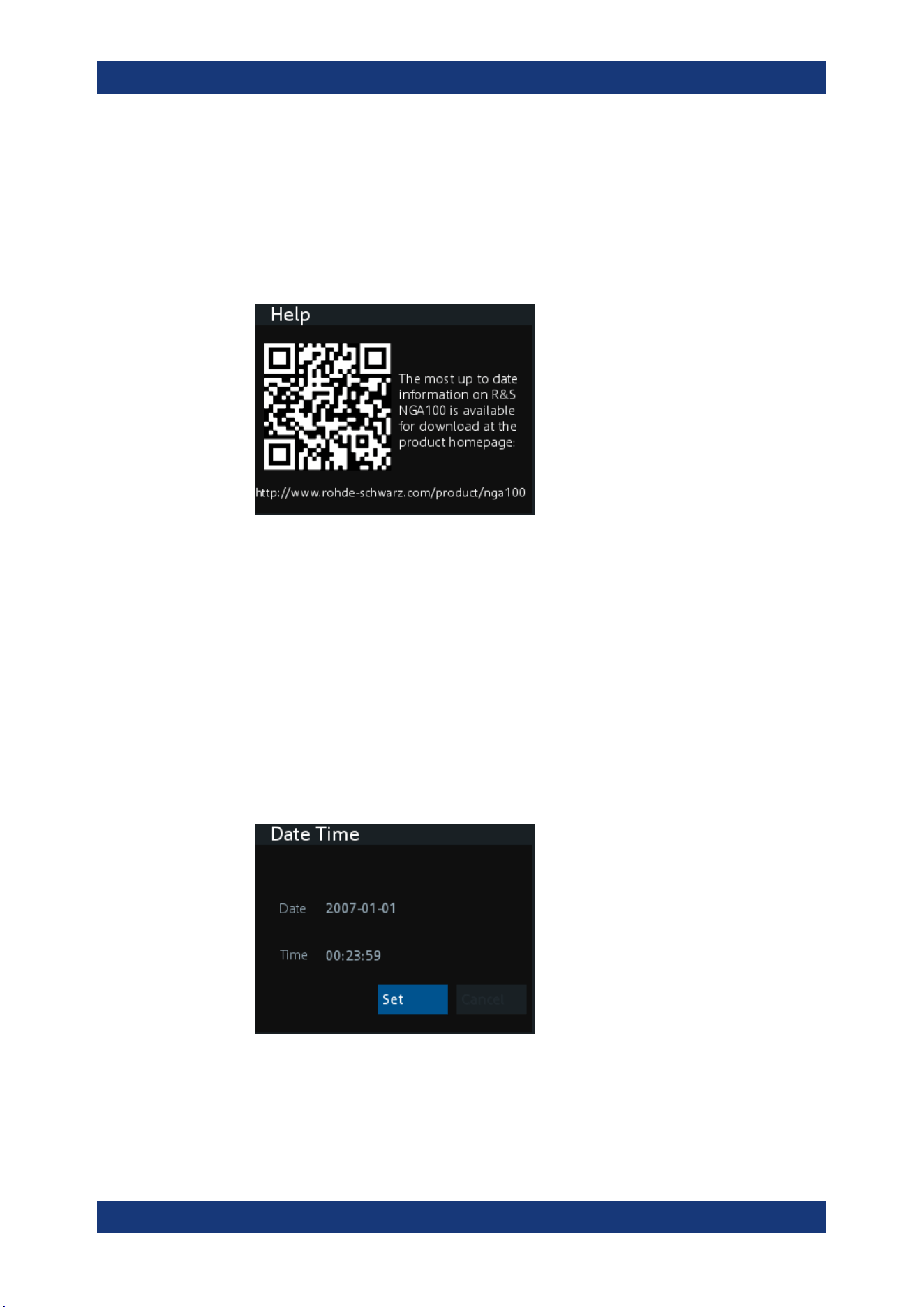
Instrument Functions
R&S
®
NGA100
74User Manual 5601.8919.02 ─ 05
6.14.7 Help
The "Help" dialog provides the internet link and QR code for the latest R&S NGA100
information.
1. Select "Help" menu item.
The R&S NGA100 displays the "Help" dialog. See Figure 6-26.
Figure 6-26: Help dialog
2. Use a QR code reader to scan the QR code to link to the online product home
page.
Alternatively, you could enter the address:
http://www.rohde-schwarz.com/product/
nga100 into a browser to access the latest help information.
6.14.8 Date Time
The "Date Time" dialog provides the configuration to set system date and time.
1. Select "Date" menu item.
The R&S NGA100 displays the "Date Time" dialog.
Figure 6-27: Date time dialog
2. Select "Set" to change the system date and time.
The R&S NGA100 displays a dialog to set date and time in "dd mm yyyy" and "hh
mm" format respectively.
General Instrument Settings

Instrument Functions
R&S
®
NGA100
75User Manual 5601.8919.02 ─ 05
3. Set the required date and time accordingly.
General Instrument Settings

Remote Control Commands
R&S
®
NGA100
76User Manual 5601.8919.02 ─ 05
7 Remote Control Commands
This chapter provides the description of all remote commands available for the R&S
NGA100 series. The commands are sorted according to the menu structure of the
instrument. A list of commands in alphabetical order is given in the "List of Command"s
at the end of this documentation.
For more information on
Messages and Command Structure, see the "Annex" at the
end of this documentation.
7.1 Common Commands
The common commands are taken from the IEEE 488.2 (IEC 625-2) standard. A par-
ticular command has the same effect on different devices. The headers of these com-
mands consist of an asterisk "*" followed by three letters.
*CLS
Clear status
Sets the status byte (STB), the standard event register (ESR) and the EVENt part of
the QUEStionable and the OPERation registers to zero. The command does not
alter the mask and transition parts of the registers. It clears the output buffer.
Usage: Setting only
*ESE <Value>
Event status enable
Sets the event status enable register to the specified value. The query returns the con-
tents of the event status enable register in decimal form.
Parameters:
<Value> Range: 0 to 255
*ESR?
Event status read
Returns the contents of the event status register in decimal form and then sets the reg-
ister to zero.
Return values:
<Contents> Range: 0 to 255
Usage: Query only
Common Commands

Remote Control Commands
R&S
®
NGA100
77User Manual 5601.8919.02 ─ 05
*IDN?
Identification
Returns the instrument identification.
Return values:
<ID> "Rohde&Schwarz,<device type>,<part number>/serial num-
ber>,<firmware version>"
Example:
Rohde&Schwarz,NGA100,5601.8002k03/100421,1.00
*OPC
Operation complete
Sets bit 0 in the event status register when all preceding commands have been execu-
ted. This bit can be used to initiate a service request. The query writes a "1" into the
output buffer when all preceding commands have been executed, which is useful for
command synchronization.
*OPT?
Option identification query
Queries the options included in the instrument. For a list of all available options and
their description, refer to the data sheet.
Usage: Query only
*RST
Reset
Sets the instrument to a defined default status. The default settings are indicated in the
description of commands.
Usage: Setting only
*STB?
Status byte query
Reads the contents of the status byte in decimal form.
Usage: Query only
*WAI
Wait to continue
Common Commands

Remote Control Commands
R&S
®
NGA100
78User Manual 5601.8919.02 ─ 05
Prevents servicing of the subsequent commands until all preceding commands have
been executed and all signals have settled (see also command synchronization and
*OPC).
Usage: Event
7.2 System Commands
The SYSTem commands perform the various system functions and configure the com-
munication interface (LAN, WLAN) for the instrument.
SYSTem:BEEPer[:IMMediate]
The instrument returns a single beep immediately.
Usage: Event
SYSTem:LOCal
This command sets the system to front panel control. The front panel control is
unlocked.
Usage: Event
SYSTem:REMote
This command sets the system to remote state. The front panel control is locked. By
pressing Remote, the front panel control will be activated.
Usage: Event
SYSTem:RWLock
This command sets the system to remote state. The front panel control is locked. You
are only able to unlock the front panel control via SCPI command
SYSTem:LOCal
on page 78.
Usage: Event
SYSTem:OPTion?
This command returns the list of options installed on the instrument.
Return values:
<arg0>
Usage: Query only
System Commands

Remote Control Commands
R&S
®
NGA100
79User Manual 5601.8919.02 ─ 05
SYSTem:TEST:BEEPer
The instrument runs the system test: Beeper Test.
Usage: Event
SYSTem:TEST:FANCtrl
The instrument runs the system test: Fan Control Test.
Usage: Event
SYSTem:TEST:KEYBacklight
The instrument runs the system test: Keypad Backlight Test.
Usage: Event
SYSTem:TEST:SCReen
The instrument runs the system test: Screen Color Test.
Usage: Event
SYSTem:COMMunicate:SOCKet:DHCP[:STATe] <arg0>
This command sets or queries LAN interface mode. ON: automatic IP address from
DHCP server; OFF: manually set IP address.
Parameters:
<arg0>
SYSTem:COMMunicate:SOCKet:IPADdress?
This command queries IP address of the LAN interface.
Return values:
<arg0>
Usage: Query only
SYSTem:COMMunicate:WLAN:CONNect
The instrument connects to the predefined wireless access point.
Available only if option R&S NGA-K102 is installed.
Usage: Event
System Commands

Remote Control Commands
R&S
®
NGA100
80User Manual 5601.8919.02 ─ 05
SYSTem:COMMunicate:WLAN:DISConnect
The instrument stops the connection to the predefined wireless access point.
Available only if option R&S NGA-K102 is installed.
Usage: Event
SYSTem:COMMunicate:WLAN:IPADdress?
This command queries the IP address of the device when the wireless interface works
as a client.
Available only if option R&S NGA-K102 is installed.
Return values:
<arg0>
Usage: Query only
SYSTem:COMMunicate:WLAN[:STATe] <arg0>
This command activates/deactivates or queries the enable state of the wireless inter-
face.
Available only if option R&S NGA-K102 is installed.
Parameters:
<arg0>
SYSTem:COMMunicate:WLAN:PASSword <arg0>
This command defines the password string of the Access Point when the wireless
interface works as a client.
Available only if option R&S NGA-K102 is installed.
Parameters:
<arg0>
Usage: Setting only
SYSTem:COMMunicate:WLAN:SSID <arg0>
This command defines or queries the SSID string of the access point when the wire-
less interface works as a client.
Available only if option R&S NGA-K102 is installed.
Parameters:
<arg0>
System Commands

Remote Control Commands
R&S
®
NGA100
81User Manual 5601.8919.02 ─ 05
7.3 Configuration Commands
The following subsystems contain the commands for channel selection, voltage and
current settings for the instrument.
7.3.1 Channel Selecting
The INSTrument:Select subsystem contains the commands for selecting the output
channels.
Each channel of the power supply is considered as separate "instrument", which is
required by the SCPI standard. Therefore, the SCPI commands use the INSTRument
node to select a channel.
You can only address the number of channels a device is equipped with, e.g. a maxi-
mum of two channels for the NGA102 and NGA142.
Example: Selecting a channel
You can select a channel either with an OUTput parameter, or just by the channel
number. This example lists all ways how you can select and query a selected channel.
// ************************************************
// Select a channel
// ************************************************
// selects channel 1
INST OUT1
// queries the channel selection
INST?
// response: "OUTPut1"
// ************************************************
// Select a channel by its number
// ************************************************
// selects channel number 1
INST:NSEL 1
// queries number of the channel selection
INST:NSEL?
// response: 1
INSTrument:NSELect <arg0>
This command defines or queries the numeric selection of a channel. Each channel of
the power supply is considered as separate "instrument“, which is required by the SCPI
standard.
Parameters:
<arg0> {1 | 2}
Configuration Commands

Remote Control Commands
R&S
®
NGA100
82User Manual 5601.8919.02 ─ 05
Example:
INSTrument:NSELect 1
Selects the output channel as Ch 1.
INSTrument:NSELect? -> 1
Return the numeric channel selection.
INSTrument[:SELect] <arg0>
This command defines or queries the channel selection. Each channel of the power
supply is considered as separate "instrument", which is required by the SCPI standard.
Parameters:
<arg0> OUTPut1 | OUTPut2 | OUTP1 | OUTP2 | OUT1 | OUT2
OUTPut1 | OUTP1 | OUT1
Ch 1
OUTPut2 | OUTP2 | OUT2
Ch 2
Example:
INSTrument OUTPut1
INSTrument OUTP1
Selects the output channel as Ch 1.
INST? -> 2
Return the output channel as Ch 2.
7.3.2 Remote Sense Setting
The VOLTage:SENSe subsystem contains the command for setting the remote sense
for the instrument.
[SOURce:]VOLTage:SENSe <arg0>
Sets or queries the remote sense state of the selected channel.
Parameters:
<arg0> EXTernal | EXT
The internal voltage sense relay in the instrument is switched on
and the connection of remote sense wires (S+, S- ) to the input
of the load become necessary.
Failure to connect remote sense can cause over voltage or
unregulated voltage output from the R&S NGA100. The voltage
sense relay remains switched on even when output is turned off.
DISable | DIS
Remote sense is disabled.
Example:
VOLT:SENS EXT
VOLT:SENS? -> EXTernal
Remote sense state is EXT.
Configuration Commands

Remote Control Commands
R&S
®
NGA100
83User Manual 5601.8919.02 ─ 05
7.3.3 Voltage Setting
The SOURce:VOLTage subsystem contains the commands for setting the voltage of
the output channels. The default unit is V.
Example: Configuring the output voltage
This example contains all commands to configure and query the output voltage.
// ************************************************
// Select the channel
// ************************************************
INST OUT1
// ************************************************
// Set the voltage value
// ************************************************
// selects a channel and sets the voltage
VOLT 10
// queries the output voltage of a channel
VOLT?
// response: 10.000
// sets the voltage to maximum or minimum respectively
VOLT MAX
VOLT MIN
// ************************************************
// Query the range of the voltage values
// ************************************************
// queries the upper and lower limit of the output voltage
VOLT? MIN
// response: 0.000
VOLT? MAX
// response: 35.05 for NGA101, NGA102 and 100.05 for NGA141, NGA142
[SOURce:]VOLTage[:LEVel][:IMMediate][:AMPLitude] <Voltage>
This command defines or queries the voltage value of the selected channel.
Parameters:
<Voltage> {<Voltage> | MINimum | MAXimum | DEFault}
<Voltage>
0.0 V to 35.05 V for NGA101 and NGA102 models (adjustable in
1 mV steps)
0.0 V to 100.05 V for NGA141 and NGA142 models (adjustable
in 10 mV steps)
MINimum
0.000E+00
MAXimum
35.05 V for NGA101 and NGA102 models
100.05 V for NGA141 and NGA142 models
Default unit: V
Configuration Commands

Remote Control Commands
R&S
®
NGA100
84User Manual 5601.8919.02 ─ 05
Example:
VOLT 10
Set the voltage value to 10 V.
VOLT? -> 10
Return the voltage value of the selected channel.
7.3.4 Current Setting
The SOURce:CURRent subsystem contains the commands for setting the current limit
of the output channels. The default unit is A.
Example: Configuring the current output
// ************************************************
// Select the channel
// ************************************************
INST OUT1
// ************************************************
// Set the current value
// ************************************************
// selects a channel and sets the current
CURR 2
// queries the current of the selected channel
CURR?
// response: 2.000
// ************************************************
// Query the range of the current values
// ************************************************
// queries the upper and lower limit of the current
CURR? MIN
// response: 0.001
CURR? MAX
// response: 6.5 for NGA101 and NGA102 and 2.03 for NGA141 and NGA142
[SOURce:]CURRent[:LEVel][:IMMediate][:AMPLitude] <Current>
This command defines or queries the current value of the selected channel.
Parameters:
<Current> <Current>
Set current in the range of 1 mA to 6.05 A for NGA101 and
NGA102 models or 1 mA to 2.03 A for NGA141 and NGA142
models.
Default unit: A
Example:
CURR 2
Set the selected channel current to 2 A.
CURR? -> 2
Return current value of the selected channel .
Configuration Commands

Remote Control Commands
R&S
®
NGA100
85User Manual 5601.8919.02 ─ 05
[SOURce:]CURRent:RANGe <arg0>
Sets or queries the current range of the selected channel.
Parameters:
<arg0> AUTO | HIGH | LOW
AUTO
The measured output current is displayed in the following:
- "A" with 10 μA resolution for current above 200 mA
- "mA" with 1 μA resolution for current below 200 mA
HIGH
The measured output current is displayed in "A" with 10 μA res-
olution.
LOW
The measured output current is displayed in "mA" with 1 μA res-
olution.
7.3.5 Combined Setting of Voltage and Current Setting
The APPLy subsystem provides a command that enables you to set the current and
voltage of a channel in one step.
APPLy <arg0>
This command defines or queries the voltage and current value of the selected chan-
nel.
Parameters:
<arg0> {<Voltage> | DEF | MIN | MAX} [, {<Current> | DEF | MIN | MAX}]
<Voltage>
Set voltage in the range of 0 V to 35.05 V for NGA101 and
NGA102 models or 100.05 V for NGA141 and NGA142 models.
DEF
Set voltage to default.
MIN
Set voltage to minimum .
MAX
Set voltage to maximum.
<Current>
Set current in the range of 1 mA to 6.05 A for NGA101 and
NGA102 models or 1 mA to 2.03 A for NGA141 and NGA142
models.
DEF
Set current to default.
MIN
Set current to minimum.
MAX
Set current to maximum.
Configuration Commands

Remote Control Commands
R&S
®
NGA100
86User Manual 5601.8919.02 ─ 05
Example:
INST OUT1
APPLY "6,2"
Set channel 1 to output 6 V and 2 A.
APPLY? -> 6, 2
Return voltage and current value of the selected channel.
7.3.6 Output Setting
The OUTPut subsystem contains the commands for activating the output channels.
Example: Activating the channels
You can activate a selected channel and turn on or off the outputs either individually or
all outputs simultaneously. This example lists all ways how you can activate and query
the outputs.
// ************************************************
// Activate a channel
// ************************************************
INST OUT1
// activates the selected channel
OUTP:SEL 1
// activates channel 1 and its output
OUTP 1
// queries the output state
OUTP?
// response: 1
// ************************************************
// Turn on all selected channels simultaneously
// ************************************************
// selects channels 1 and 2
// sets the voltage and current values for both channels
// activates both channels
INST:OUT1
VOLT 12
CURR 0.1
OUTP:SEL 1
INST:OUT2
VOLT 12
CURR 0.2
OUTP:SEL 1
// turns on the output of both channels
OUTP:GEN 1
OUTPut[:STATe] <arg0>
This command defines or queries for output state for the previous selected channel.
Parameters:
<arg0> {OFF | ON | 0 | 1}
Configuration Commands

Remote Control Commands
R&S
®
NGA100
87User Manual 5601.8919.02 ─ 05
ON | 1
Output state will be turned on.
OFF | 0
Output state will be turned off.
*RST: OFF | 0
Example:
INST OUT1
OUTP ON
Ch 1 and output state will be activated; i.e. Ch 1 and Output key
on the front panel will be illuminated.
OUTP? -> 1
Return the output state.
OUTPut:FUSion <arg0>
Sets or queries the output fusion state for 2-channel model.
Parameters:
<arg0> OFF | SERies | PARallel
OFF
Output fusion state is off.
SERies
Output fusion state is set to series.
PARallel
Output fusion state is set to parallel.
Example:
OUTP:FUS SER
OUTP:FUS? -> SER
Output fusion state is set to series.
OUTPut:GENeral <arg0>
This command activates or queries the instrument master output state.
If the master output state is activated, the Output key on the front panel will be illumi-
nated.
Parameters:
<arg0> {OFF | ON | 0 | 1}
ON | 1
Output state will be activated
OFF | 0
Output state will be deactivated
Configuration Commands

Remote Control Commands
R&S
®
NGA100
88User Manual 5601.8919.02 ─ 05
Example:
INST OUT1
OUTP:SEL ON
Volt 12
Curr 0.1
Ch 1 is activated.
INST OUT2
OUTP:SEL ON
Volt 12
Curr 0.2
Ch 2 is activated.
OUTP:GEN ON
Ch 1 and Ch 2 and Output state are activated.
OUTP:GEN? -> 1
Return output state of the channel.
OUTPut:MODE?
Queries the output operating mode of the previous selected channel
Return values:
<arg0> {OFF | CV | CC}
OFF
Output is turned off.
CV
Output mode changed to constant voltage mode.
CC
Output mode changed to constant current mode.
*RST: OFF
Example: OUTP:MODE? -> CV
Output mode has changed to constant voltage mode.
Usage: Query only
OUTPut:SELect <arg0>
This command activates or queries the instrument channel state of the previous
selected channel.
If the selected channel is activated, the respective channel key (i.e. Ch 1, Ch 2) on the
front panel will be illuminated.
Parameters:
<arg0> {OFF | ON | 0 | 1}
ON | 1
Selected channel will be activated.
OFF | 0
Selected channel will be deactivated.
*RST: OFF | 0
Configuration Commands

Remote Control Commands
R&S
®
NGA100
89User Manual 5601.8919.02 ─ 05
Example:
INST OUT1
OUTP:SEL ON
Ch 1 is activated.
OUTP:SEL? -> 1
Return the state of the selected channel.
OTP:TRIPped?
Queries the overtemperature protection (OTP) tripped state of the previous selected
channel.
It is tripped if an OTP event occurs.
Return values:
<arg0> {OFF | ON | 0 | 1}
ON | 1
OTP event occurs.
OFF | 0
OTP event not occurs.
*RST: OFF | 0
Example: OUTP:TRIP? -> 1
OTP event occurs.
Usage: Query only
7.3.7 Fuse Setting
The FUSE subsystem contains the commands for overcurrent protection parameters
such as activating fuses and setting fuse parameters of the output channels. The
default unit is A.
Configuration Commands

Remote Control Commands
R&S
®
NGA100
90User Manual 5601.8919.02 ─ 05
Example: Configuring fuses
This example contains all commands to configure and query the fuse states and set-
tings.
// ************************************************
// Activate a fuse
// ************************************************
INST OUT1
// selects a channel and activates the overcurrent protection
FUSE 1
// queries the state of the overcurrent protection in the selected channel
FUSE?
// response: 1
// ************************************************
// Set a delay time for the overcurrent protection. The delay time
// takes effect when the channel output is turned on.
// ************************************************
// sets 0.05 s delay for the overcurrent protection
FUSE:DEL 0.05
// queries the currently set delay time of the overcurrent protection
// in the selected channel
FUSE:DEL?
// response: 0.05
// sets the delay time to maximum, minimum respectively
FUSE:DEL MAX
FUSE:DEL MIN
// ************************************************
// Query the range of the overcurrent protection delay time
// ************************************************
// queries the upper and lower limit of the
// overcurrent protection delay time in s
FUSE:DEL? MIN
// response: 0
FUSE:DEL? MAX
// response: 10
// ************************************************
// Query a tripped overcurrent protection
// ************************************************
INST OUT1
//queries whether the OCP in channel 1 has tripped
FUSE:TRIP?
//response: 1 OCP is tripped
//response: 0 OCP is not tripped
//resets a tripped OCP in the selected channel
FUSE:TRIP:CLEar
// ************************************************
// Link the electronic overcurrent protection of the channels logically
// ************************************************
INST OUT1
// links the overcurrent protection of channel 1 with channel 2
Configuration Commands

Remote Control Commands
R&S
®
NGA100
91User Manual 5601.8919.02 ─ 05
FUSE:LINK 2
// queries the combined overcurrent protection of the selected channel
FUSE:LINK? 2
// response 1
// ************************************************
// Unlink linked overcurrent protection
// ************************************************
FUSE:UNLink 2
// queries the combined overcurrent protection of the selected channel
FUSE:LINK? 2
// response 0
FUSE:DELay <Delay>
This command defines and queries the fuse delay for the previous selected channel.
Parameters:
<Delay> {<Delay> | MIN | MAX}
<delay>
0 s to 10 s (adjustable in 0.010 s steps e.g. FUSE:DEL 0.010 =
0.01 s)
MIN
Set fuse delay to minimum.
MAX
Set fuse delay to maximum.
Default unit: ms
Example:
INST OUT1
FUSE:DEL 0.050
Set fuse delay of channel 1 to 50 ms.
FUSE:DEL? -> 0.05
Return the fuse delay time of the selected channel.
FUSE:LINK <arg0>
This command defines or queries the channel fuses (fuse linking) for the previous
selected channel.
Parameters:
<arg0> 1
channel Ch 1
2
channel Ch 2
Example:
INST OUT1
FUSE:LINK 2
Fuse Ch 1 is linked with Ch 2
FUSE:LINK? 2 -> 1
If the fuse of Ch 1 is linked with Ch 2, a "1" is returned.
Configuration Commands

Remote Control Commands
R&S
®
NGA100
92User Manual 5601.8919.02 ─ 05
FUSE:TRIPped?
This command queries the fuse tripped of the previous selected channel.
Return values:
<arg0> ON
Fuse is tripped.
OFF
Fuse is not tripped.
Example:
INST OUT1
FUSE:TRIP? -> 0
Fuse of Ch 1 has not tripped.
Usage: Query only
FUSE:UNLink <arg0>
This command unlinks the channel fuses (fuse linking) for the previous selected chan-
nel.
Parameters:
<arg0> 1
channel Ch 1
2
channel Ch 2
Example:
INST OUT1
FUSE:LINK 2
FUSE:UNL 2
Fuse Ch 1 is unlinked with Ch 2
Usage: Setting only
FUSE[:STATe] <arg0>
This command defines or queries the fuse for the previous selected channel.
Parameters:
<arg0> {0 | 1}
1
Fuse will be activated.
0
Fuse will be deactivated.
*RST: OFF | 0
Example:
INST OUT1
FUSE ON
Fuse of Ch 1 is activated
FUSE? -> 1
Return fuse state of the selected channel.
Configuration Commands

Remote Control Commands
R&S
®
NGA100
93User Manual 5601.8919.02 ─ 05
7.3.8 OVP Setting
The VOLTage:PROTection subsystem contains the commands for setting the over-
voltage protection parameters for the output channels. The default unit is V.
Configuration Commands

Remote Control Commands
R&S
®
NGA100
94User Manual 5601.8919.02 ─ 05
Example: Configuring the overvoltage protection
// ************************************************
// Set the overvoltage protection value
// ************************************************
INST OUT1
//activates the OVP of the previous selected channel
VOLT:PROT 1
// selects a channel and sets the OVP
VOLT:PROT:LEV 5
// queries the output overvoltage value of a channel
VOLT:PROT:LEV?
// response: 5
// queries the OVP state of the previous selected channel
VOLT:PROT?
// response: 1
// sets the overvoltage protection to maximum,
// or minimum respectively
VOLT:PROT:LEV MAX
VOLT:PROT:LEV MIN
// ************************************************
// Query the range of the overvoltage protection values
// ************************************************
// queries the upper and lower limit
VOLT:PROT:LEV? MIN
// response: 0.100
VOLT:PROT:LEV? MAX
// response: 36.0 for NGA101, NGA102 and 102 for NGA141, NGA142
// ************************************************
// Query a tripped overvoltage protection
// ************************************************
INST OUT1
// queries whether the OVP in channel 1 has tripped
VOLT:PROT:TRIP?
// response: 1 OVP is tripped
// response: 0 OVP is not tripped
// resets a tripped OVP in the selected channel
VOLT:PROT:CLEar
// ************************************************
// Set the overvoltage protection mode
// ************************************************
INST OUT1
// sets OVP protected mode for channel1
VOLT:PROT:MODE PROT
// queres the OVP mode
VOLT:PROT:MODE PROT?
// response: "protected"
Configuration Commands

Remote Control Commands
R&S
®
NGA100
95User Manual 5601.8919.02 ─ 05
[SOURce:]VOLTage:PROTection:MODE <arg0>
This command defines or queries the OVP mode for the previous selected channel.
Parameters:
<arg0> MEASured | PROTected
MEASured
The OVP switches off if the measured value exceeds the thresh-
old.
PROTected
If the adjusted threshold is exceeded the output of the instru-
ment will be not switched on; additionally the measured value is
monitored (please also refer to function MEASured).
Example:
INST OUT1
VOLT:PROT:MODE PROT
Sets OVP protected mode for Ch 1.
VOLT:PROT:MODE? -> PROTected
Return the selected channel OVP mode.
[SOURce:]VOLTage:PROTection:TRIPped?
This command queries the OVP tripped status of the previous selected channel.
Return values:
<arg0> ON | OFF
ON
OVP is tripped
OFF
OVP is not tripped
Example:
INST OUT1
VOLT:PROT:TRIP? -> OFF
OVP of Ch 1 has not tripped.
Usage: Query only
[SOURce:]VOLTage:PROTection[:STATe] <arg0>
This command defines or queries the OVP state for the previous selected channel.
Parameters:
<arg0> 1 | 0
1
OVP is activated.
0
OVP is deactivated.
Configuration Commands

Remote Control Commands
R&S
®
NGA100
96User Manual 5601.8919.02 ─ 05
Example:
INST OUT1
VOLT:PROT ON
OVP of Ch 1 is activated.
VOLT:PROT? -> 1
Return the OVP state of the selected channel.
[SOURce:]VOLTage:PROTection:LEVel <Voltage>
This command defines or queries the OVP value of the previous selected channel.
Parameters:
<Voltage> {<Voltage> | MIN | MAX}
<Voltage>
Set the OVP value in the range of 0 mV up to 36 V for NGA101
and NGA102 models or 0 mV up to 102 V for NGA141 and
NGA142 models (adjustable in 100 mV steps):
MIN
Set the OVP value to minimum.
MAX
Set the OVP value to maximum.
Default unit: V
Example:
INST OUT1
VOLT:PROT:LEV 5
Set the OVP value of Ch 1 to 5 V.
VOLT:PROT:LEV?
Return the selected channel OVP value.
[SOURce:]VOLTage:PROTection:CLEar
This command resets the OVP state of the selected channel. If the OVP has tripped
the OVP message on the display will be cleared for the selected channel.
Usage: Event
7.3.9 OPP Setting
The POWer:PROTection subsystem contains the commands for setting the over-
power protection parameters for the output channels. The default unit is W.
Configuration Commands

Remote Control Commands
R&S
®
NGA100
97User Manual 5601.8919.02 ─ 05
Example: Configuring the overpower protection
// ************************************************
// Set the overpower protection value
// ************************************************
INST OUT1
//activates the OPP of the previous selected channel
POW:PROT 1
// selects a channel and sets the OPP
POW:PROT:LEV 5
// queries the output overvoltage value of a channel
POW:PROT:LEV?
// response: 5
// queries the OPP state of the previous selected channel
POW:PROT?
// response: 1
// sets the overvoltage protection to maximum,
// or minimum respectively
POW:PROT:LEV MAX
POW:PROT:LEV MIN
// ************************************************
// Query the range of the overpower protection values
// ************************************************
// queries the upper and lower limit
POW:PROT:LEV? MIN
// reponse: 0.0
POW:PROT:LEV? MAX
// reponse: 41.0
// ************************************************
// Query a tripped overpower protection
// ************************************************
INST OUT1
// queries whether the OPP in channel 1 has tripped
POW:PROT:TRIP?
// response: 1 OPP is tripped
// response: 0 OPP is not tripped
// resets a tripped OPP in the selected channel
POW:PROT:CLEar
[SOURce:]POWer:PROTection:LEVel <Power>
This command defines or queries the OPP value of the previous selected channel.
Parameters:
<Power> {<Voltage> | MIN | MAX}
<Voltage>
Set the OPP value in the range of 0 W up to 41W (adjustable in
100 mW steps)
MIN
Set the OPP value to minimum.
Configuration Commands

Remote Control Commands
R&S
®
NGA100
98User Manual 5601.8919.02 ─ 05
MAX
Set the OPP value to maximum
Default unit: W
Example:
INST OUT1
POW:PROT:LEV 5
Set the OPP value of channel 1 to 5 W.
POW:PROT:LEV? -> 5
Return the selected channel OPP value.
[SOURce:]POWer:PROTection:TRIPped?
This command queries the OPP tripped status of the previous selected channel
Return values:
<arg0> 1 | 0
1
OPP is tripped.
0
OPP is not tripped.
Example:
INST OUT1
POW:PROT:TRIP? -> 0
OPP state of Ch 1 has not tripped.
Usage: Query only
[SOURce:]POWer:PROTection[:STATe] <arg0>
This command defines or queries the OPP state for the previous selected channel.
Parameters:
<arg0> ON | OFF | 1 | 0
ON | 1
OPP is activated.
OFF | 0
OPP is deactivated.
Example:
INST OUT1
POW:PROT ON
OPP of Ch 1 is activated.
POW:PROT?
Return the OPP state of the selected channel.
[SOURce:]POWer:PROTection:CLEar
This command resets the OPP state of the selected channel. If the OPP has tripped
the red blinking OPP message on the display will be cleared for the selected channel.
Usage: Event
Configuration Commands

Remote Control Commands
R&S
®
NGA100
99User Manual 5601.8919.02 ─ 05
7.4 Measurement Commands
The MEASure subsystem provides commands to query the voltage and current values
of a channel.
MEASure[:SCALar]:CURRent[:DC]?
This command queries the measured current value of the previous selected channel.
Return values:
<Current> <numeric_value>
Return the measured current.
Default unit: A
Example: MEAS:CURR? -> 1.000
Usage: Query only
MEASure[:SCALar]:POWer?
This command queries the measured power value of the previous selected channel.
Return values:
<Power> <Numeric_value>
Return the measured power value.
Default unit: W
Example: MEAS:POW? -> 3.00E+00
Return the measured power value of the selected channel.
Usage: Query only
MEASure[:SCALar][:VOLTage][:DC]?
This command queries the measured voltage value of the previous selected channel.
Return values:
<Voltage> <numeric_value>
Return the measured voltage.
Default unit: V
Example: MEAS? -> 1.000E+00
Usage: Query only
7.5 Advanced Operating Commands
The following shows the subsystem that contains the commands for configuring the
arbitrary function, easyramp and Digital I/O functions.
Advanced Operating Commands

Remote Control Commands
R&S
®
NGA100
100User Manual 5601.8919.02 ─ 05
7.5.1 Arbitrary Commands
The ARBitrary subsystem contains the commands for configuring an arbitrary
sequence for the output channels.
Example: Configuring an arbitrary sequence
This programming example generates an arbitrary sequence for a selected channel.
The sequence starts at 1 V and 1 A for 1 sec, and both values are incremented each
second by 1. The generated arbitrary waveform is transferred to Ch 1. When activated,
the R&S NGA100 provides the arbitrary waveform at the output of the selected chan-
nel, and repeats it 10 times.
ARBitrary:CLEar
This command clears the previous defined arbitrary waveform data for channel 1.
Usage: Event
ARBitrary:DATA <arg0>
Defines or queries the arbitrary points for channel 1. The dwell time between two
points is from 10ms to 600s.
Parameters:
<arg0> <Voltage1, Current1, Time1, Voltage2, Current2, Time2,..., Volt-
age128, Current128, Time128>
Voltage1 ... Voltage128
Defines the arbitrary points of the voltage.
Current1 ... Current128
Defines the arbitrary points of the current.
Time1 ... Time128
Defines the arbitrary points of the time (The unit for time is ms).
Example:
ARB:DATA "10.5,3,10,20,2,1000,15,2.1,10000"
ARBitrary:RCL <arg0>
This command recalls EasyArb settings and previous defined arbitrary points from the
respective memory locations M1-M5.
Parameters:
<arg0> Range: 0..4
Usage: Setting only
ARBitrary:REPetitions <Repetitions>
This command defines or queries the repetition of the defined arbitrary waveform for
channel 1.
Advanced Operating Commands

Remote Control Commands
R&S
®
NGA100
101User Manual 5601.8919.02 ─ 05
Note: If the repetition is set to "0", the arbitrary waveform repeats continuously.
Parameters:
<Repetitions> 0..255
Example:
ARB:REP 10
Set the repetition rate of the defined arbitrary waveform as 10.
ARB:REP? -> 10
Return the defined repetition rate of the selected channel.
ARBitrary:POINts?
This command returns the number of arbitrary points of EasyArb waveform.
Return values:
<arg0>
Usage: Query only
ARBitrary[:STATe] <arg0>
This command activates/deactivates or queries the EasyArb state. ON: Ch 1 is ready
to run arb waveform.
Parameters:
<arg0> {OFF | ON}
ON
EasyArb state is activated.
OFF
EasyArb state is deactivated.
ARBitrary:SAV <arg0>
This command saves EasyArb settings and previous defined arbitrary points into the
respective memory locations M1-M5.
Parameters:
<arg0> Range: 0..4
Example: INST 1
ARB:DATA 10,1,0,5,0
ARB:REP 10
ARB:SAV 1
Usage: Setting only
ARBitrary:STARt
This command starts the previous transferred EasyArb waveform in channel 1 if Easy-
Arb is enabled.
Usage: Event
Advanced Operating Commands

Remote Control Commands
R&S
®
NGA100
102User Manual 5601.8919.02 ─ 05
ARBitrary:STOP
This command stops the EasyArb waveform in channel 1 if EasyArb is running.
Usage: Event
7.5.2 EasyRamp Commands
The VOTage:RAMP subsystem contains the commands for configuring the ramp func-
tion for the output channels.
[SOURce:]VOLTage:RAMP:DURation <Time>
This command sets/queries the EasyRamp duration of the previous selected channel
in seconds. 0.01 s to 10 s in steps of 0.01 s.
Parameters:
<Time> Range: 0.010 to 10
*RST: 0.010
Default unit: ms
[SOURce:]VOLTage:RAMP[:STATe] <arg0>
This command defines/queries the EasyRamp state for the previous selected channel.
Parameters:
<arg0> {OFF | ON}
ON
EasyRamp function is activated.
OFF
EasyRamp function is disabled.
7.5.3 DIO Commands
The DIO subsystem contains the commands for configuring a Digital I/O function for
the output channels.
TRIGger:DIRection:DIO<IO> <arg0>
This command sets or queries the specified Digital I/O line to function as Trigger Input
or Trigger Output.
Suffix:
<IO>
.
1..4
Parameters:
<arg0> OUTPut | INPut
Example:
TRIG:DIR:DIO2 OUT
Advanced Operating Commands

Remote Control Commands
R&S
®
NGA100
103User Manual 5601.8919.02 ─ 05
TRIGger[:ENABle]:DIO<IO> <arg0>
This command sets or queries the state of the specified Digital I/O line.
The state is disabled when any setting has been changed.
Suffix:
<IO>
.
1..4
Parameters:
<arg0> {OFF | ON}
ON
Enable the state for Digital I/O line.
OFF
Disable the state for Digital I/O line.
*RST: OFF
TRIGger:IN:ARBitrary:DIO<IO> <arg0>
This command sets or queries the operation mode when starting EasyArb by Trig IN.
Suffix:
<IO>
.
1..4
Parameters:
<arg0> PULSe | LEVel
PULSe
Starts EasyArb when trigger signal activated.
LEVel
Starts EasyArb when trigger signal activated and stops when
trigger signal de-activated.
*RST: PULSe
Example:
TRIG:IN:ARB:DIO1 PULS
TRIGger:IN:RESPonse:DIO<IO> <arg0>
This command sets or queries the output response of the trigger input of the specified
Digital I/O line.
Suffix:
<IO>
.
1..4
Parameters:
<arg0> ON | OFF | TOGGle | INHibit | ARBitrary
ON
Output is switched on.
OFF
Output is switched off.
TOGGle
Output state is toggled.
Advanced Operating Commands

Remote Control Commands
R&S
®
NGA100
104User Manual 5601.8919.02 ─ 05
INHibit
Output state remains off as long as the TRIG IN signal is activa-
ted.
ARBitrary
Starts the EasyArb function. If level signal is selected, the Easy-
Arb function is stopped when TRIG IN signal is deactivated.
*RST: OFF
TRIGger:IN:SOURce:DIO<IO> <arg0>
This command sets or queries the source under control of the trigger input of the speci-
fied Digital I/O line.
Suffix:
<IO>
.
1..4
Parameters:
<arg0> CH1
Trigger input source from Ch 1.
CH2
Trigger input source from Ch 2.
*RST: CH1
TRIGger:LOGic:DIO<IO> <arg0>
This command sets or queries the trigger logic (Active High/Active Low) of the speci-
fied Digital I/O line.
Suffix:
<IO>
.
1..4
Parameters:
<arg0> LOW | HIGH
*RST: HIGH
TRIGger:MASTer[:STATe] <arg0>
This command defines or queries the master enable state for the Digital I/O interface.
The state is disabled when any setting has been changed.
Parameters:
<arg0> {OFF | ON}
ON
"Master Enable" state is activated for all DIO interfaces.
OFF
"Master Enable" state is deactivated for all DIO interfaces.
*RST: OFF
Advanced Operating Commands

Remote Control Commands
R&S
®
NGA100
105User Manual 5601.8919.02 ─ 05
TRIGger:OUT:CONDition:DIO<IO> <arg0>
This command sets the trigger condition of the trigger output of the specified Digital I/O
line.
The line triggers when the output of the specified control source is turned off or on
Suffix:
<IO>
.
1..4
Parameters:
<arg0> ON | OFF | FUSetrip | CCMode | VOLTlevel | CURRlevel |
CRITevent | ARBitrary
ON
Trigger output is turned on.
OFF
Trigger output is turned off.
FUSetrip
Trigger output is linked to fuse tripped event.
VOLTlevel
Trigger output is linked to a set voltage level event.
CURRlevel
Trigger output is linked to a set current level event.
CRITevent
Trigger output is linked to a critical triggered event.
ARBitrary
Trigger output is linked to a EasyArb event.
*RST: ON
TRIGger:OUT:CRITevent:DIO<IO> <arg0>
This command sets or queries the critical event of the trigger output of the specified
Digital I/O line.
Suffix:
<IO>
.
1..4
Parameters:
<arg0> OVP | OPP | OTP
OVP
Trigger output is linked to the OVP event
OPP
Trigger output is linked to the OPP event
OTP
Trigger output is linked to the OTP event
*RST: OVP
Advanced Operating Commands

Remote Control Commands
R&S
®
NGA100
106User Manual 5601.8919.02 ─ 05
TRIGger:OUT:CURRlevel:DIO<IO> <Current>
This command sets or queries the threshold current level of the trigger output of the
specified Digital I/O line.
Triggers when output current level exceeds or equals to the set level.
Suffix:
<IO>
.
1..4
Parameters:
<Current> *RST: 3.000
Default unit: A
TRIGger:OUT:SOURce:DIO<IO> <arg0>
This command sets or queries the control source of the trigger output of the specified
Digital I/O line.
Suffix:
<IO>
.
1..4
Parameters:
<arg0> CH1
Trigger output source from Ch 1.
CH2
Trigger output source from Ch 2.
*RST: CH1
TRIGger:OUT:VOLTlevel:DIO<IO> <Voltage>
This command sets or queries the threshold voltage level of the trigger output of the
specified Digital I/O line.
Triggers when output voltage level exceeds or equals to the set level.
Suffix:
<IO>
.
1..4
Parameters:
<Voltage> *RST: 0.0
Default unit: V
TRIGger:RCL <arg0>
This command recalls DIO settings from the respective memory locations M1-M5.
Parameters:
<arg0> Range: 0..4
Example:
TRIG:RCL 1
Usage: Setting only
Advanced Operating Commands

Remote Control Commands
R&S
®
NGA100
107User Manual 5601.8919.02 ─ 05
TRIGger:SAV <arg0>
This command saves DIO settings into the respective memory locations M1-M5
Parameters:
<arg0> Range: 0..4
Example: TRIG:SAV 1
Usage: Setting only
7.6 Data and File Management Commands
The DATA and HCOPy subsystem contains commands for managing the files in the
instrument and external USB stick.
The LOG subsystem contains the commands for managing the data logging of the
instrument.
HCOPy:DATA?
This command queries current screen content. BMP format is supported.
Return values:
<arg0>
Usage: Query only
HCOPy:SIZE:X?
This command returns the horizontal expansion of the screenshots.
Return values:
<arg0>
Usage: Query only
HCOPy:SIZE:Y?
This command returns the vertical expansion of the screenshots.
Return values:
<arg0>
Usage: Query only
LOG[:STATe] <arg0>
Sets or queries the data logging state.
Parameters:
<state>
Data and File Management Commands

Remote Control Commands
R&S
®
NGA100
108User Manual 5601.8919.02 ─ 05
ON | 1
Data logging function is enabled.
OFF | 0
Data logging function is disabled.
*RST: 0
Example:
LOG ON
LOG? -> 1
Data logging function is activated.
DATA:DATA? <>
DATA:DATA?? <>
Returns the logging file data of the selected file.
Parameters:
<filepath> Filepath of the logging file data.
Example:
DATA:DATA?
"/tmp/usbhd-sdb1/log-20210101T101632.csv" ->
#Device,NGA142
#Device Name,rs-instrument.local
#Format,LOG
#Date,2021-1-1
#Version,2.001 009F41098
#Logging Interval[s],0.1 Time-
stamp,U1[V],I1[A],P1[W],U2[V],I2[A],P2[W]
10:16:33.370,16.855,0.00010,0.00,12.028,0.00026,0.00,
10:16:33.484,16.855,0.00010,0.00,12.028,0.00026,0.00, "
Usage: Query only
DATA:LIST?
Queries all files in internal memory ('/int/') and external memory ('/USB').
Example: DATA:LIST? ->
"log-20210101T101557.csv,log-20210101T101632.csv,log-2021
0101T110506.csv,"
Usage: Query only
7.7 Firmware Update
The following shows the subsystem that contains the commands for firmware update
function.
DIAGnostic:SERVice:FWUP <arg0>
Starts instrument firmware update remotely.
Firmware Update

Applications
R&S
®
NGA100
110User Manual 5601.8919.02 ─ 05
8 Applications
8.1 Parallel and Series Mode
It is assumed that only qualified and trained personnel service the power supplies and
the connected loads.
Use only the R&S NGA100 power supply series when operating the channels in a ser-
ies or parallel mode to increase the output voltage and current.
Series connection
A series connection may cause dangerous voltages.
To increase output voltage and currents, it is possible to operate the channels in series
or parallel mode. In general, the output voltages of R&S NGA100 to be combined are
independent.
8.1.1 Series Mode
This type of interconnection adds the individual output voltages. The same current
flows through all outputs. The current limits for the outputs wired in series should be
set to the identical value. If one of the outputs exceeded the current limit, the total volt-
age will naturally collapse. See
Chapter 5.5, "Operation Modes", on page 38.
It is advisable to set the voltages of all connected channels voltages to a similar value
to distribute the loads evenly (not absolutely necessary). When both channels are con-
nected in a series mode and if a (low resistance) load is connected; there is a chance
of damaging a channel when that channel is switch off. This is due to the protection
diode working as a bypass to connect the other channel in a series mode. Once the
protection diode is shorted, the channel will be defective.
Therefore, it is necessary to always have all channels or no channel at all switched on.
If the instrument switches to constant current output mode (CC) during a series con-
nection, the voltage display becomes inaccurate.
Parallel and Series Mode
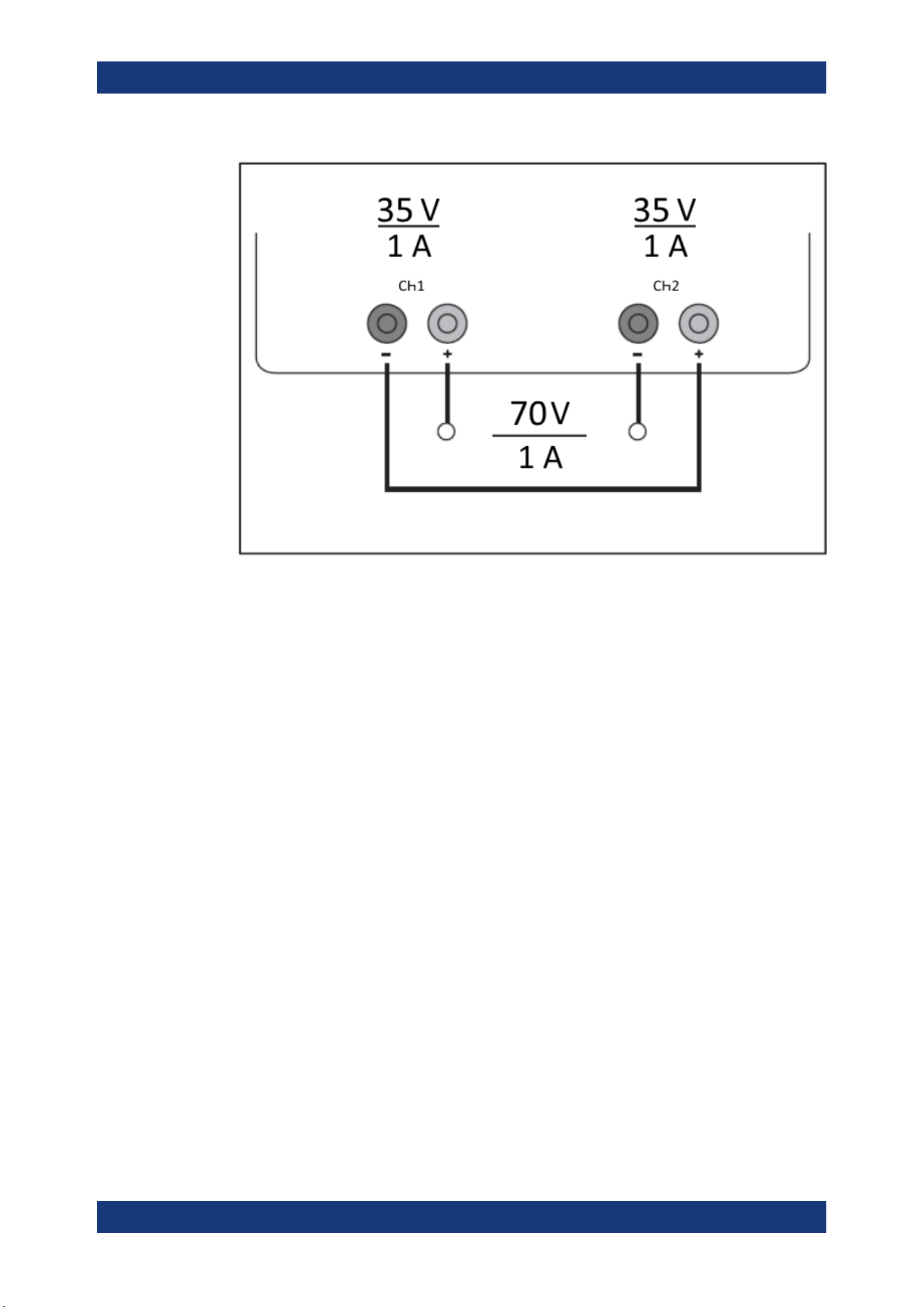
Applications
R&S
®
NGA100
111User Manual 5601.8919.02 ─ 05
Figure 8-1: Example of series connection
8.1.2 Parallel Mode
If it is necessary to increase the total current, the power supply outputs must be wired
in parallel. The maximum total current is the sum of the individual currents of all sour-
ces connected in parallel. The output voltages for the individual outputs should be set
to the same voltage value as precisely as possible. For slight voltage differences, it is
common in this operating mode to first charge a voltage output up to the current limit;
the other voltage output provides the remaining current. See
"Principles of operation in
parallel mode"
on page 112.
For power supplies that are connected in parallel, it is possible that compensating cur-
rents flow within the power supplies. The use of power supplies by other manufactur-
ers, which are potentially not overload proof, can cause destruction of these units as
currents may be distributed unevenly.
Parallel and Series Mode
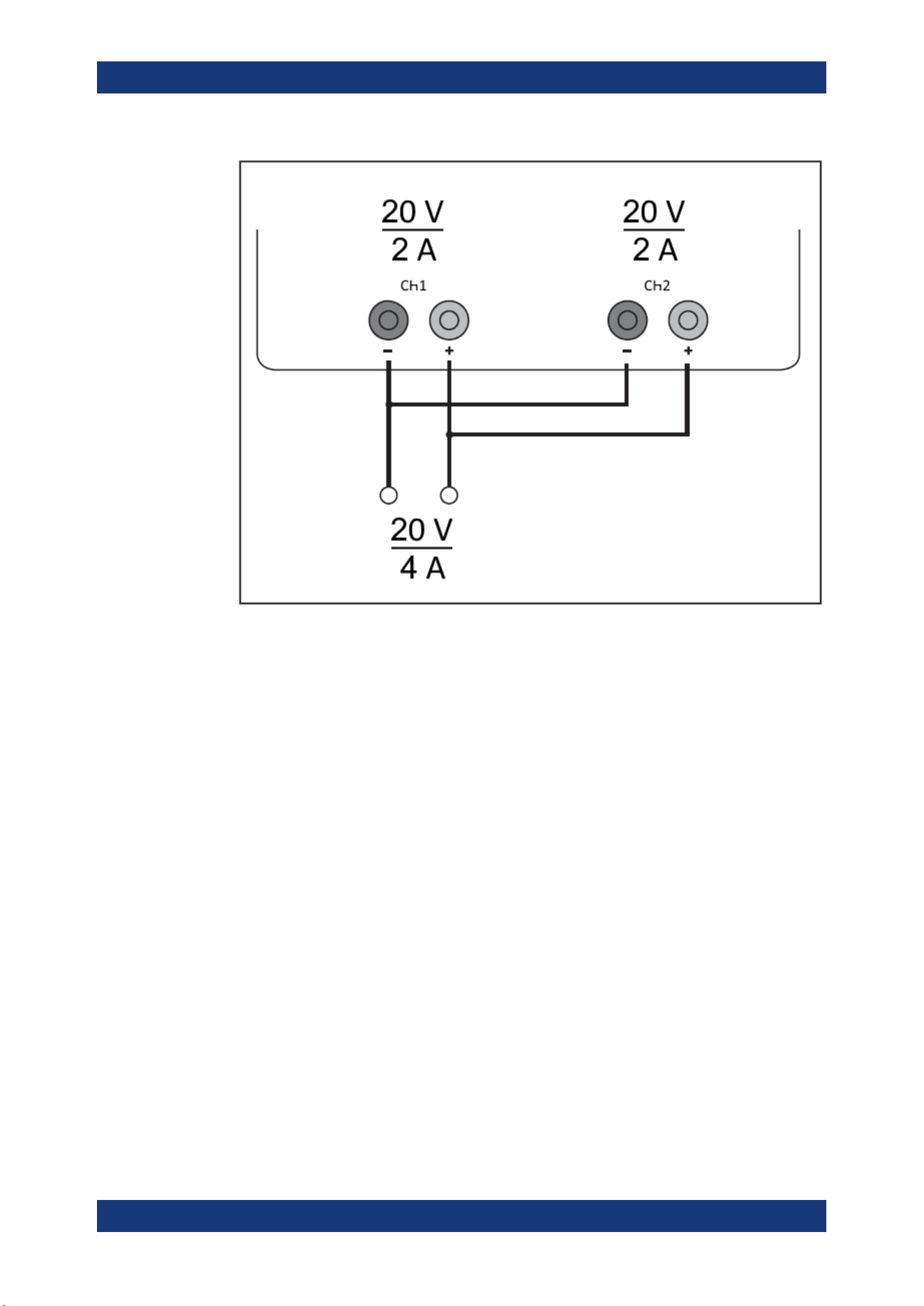
Applications
R&S
®
NGA100
112User Manual 5601.8919.02 ─ 05
Figure 8-2: Example of parallel connection
Principles of operation in parallel mode
Generally, a higher current will first be supplied from the channel with the higher output
voltage. Once this channel reaches its power limit, the remaining current will be made
available by the channel that is connected in parallel. In this scenario, it is unpredicta-
ble which channel will supply the higher current because it is also possible for channels
with identical voltage values to display a low voltage difference.
By increasing the voltage slightly, the load distribution can be manipulated. If the volt-
age for a channel is to be increased by 50mV, for instance (by a set of identical
cables), the current will initially be provided by this channel.
If you wish to distribute the load to multiple channels, it is recommended to set the cur-
rent limit of the channel that is to supply the main current to a fraction of the current.
This approach handles the semiconductor with care and improves the heat dissipation,
as the power loss is distributed more evenly.
Parallel and Series Mode

Additional Basics on Remote Control
R&S
®
NGA100
113User Manual 5601.8919.02 ─ 05
Annex
A Additional Basics on Remote Control
A.1 Messages and Command Structure
A.1.1 Messages
Instrument messages are employed in the same way for all interfaces, if not indicated
otherwise in the description.
●
Structure and syntax of the instrument messages:
Chapter A.1.2, "SCPI Command
Structure"
, on page 114
●
Detailed description of all messages:
Chapter 7, "Remote Control Commands",
on page 76
There are different types of instrument messages:
●
Commands
●
Instrument responses
Commands
Commands (program messages) are messages which the controller sends to the
instrument. They operate the instrument functions and request information. The com-
mands are subdivided according to two criteria:
Effects on the instrument:
●
Setting commands cause instrument settings such as a reset of the instrument or
setting the output voltage.
●
Queries return data for remote control, e.g. for identification of the instrument or
polling a parameter value. Queries are formed by appending a question mark to
the command header.
Applied standards:
●
The function and syntax of the common commands are precisely defined in stan-
dard IEEE 488.2. If implemented, they are used identically on all instruments. They
refer to functions such as management of the standardized status registers, reset
and self-test.
●
Instrument control commands refer to functions depending on the features of the
instrument such as voltage settings. Many of these commands have also been
standardized by the SCPI committee. These commands are marked as "SCPI
compliant" in the command reference chapters. Commands without this SCPI label
Messages and Command Structure
Additional Basics on Remote Control
R&S
®
NGA100
114User Manual 5601.8919.02 ─ 05
are device-specific, however, their syntax follows SCPI rules as permitted by the
standard.
Instrument responses
Instrument responses (response messages and service requests) are messages which
the instrument sends to the controller after a query. They can contain measurement
results, instrument settings and information on the instrument status.
A.1.2 SCPI Command Structure
SCPI commands consist of a so-called header and, usually, one or more parameters.
The header and the parameters are separated by a whitespace. The headers can con-
sist of several mnemonics (keywords). Queries are formed by appending a question
mark directly to the header. The commands can be either device-specific or device-
independent (common commands). Common and device-specific commands differ in
their syntax.
Syntax for Common Commands
Common (= device-independent) commands consist of a header preceded by an aster-
isk (*) and possibly one or more parameters.
Table A-1: Examples of Common Commands
Command Command Name Description
*RST
Reset Resets the instrument.
*ESE
Event Status Enable Sets the bits of the event status
enable registers.
*ESR?
Event Status Query Queries the content of the event
status register.
*IDN?
Identification Query Queries the instrument identifica-
tion string.
Syntax for Device-Specific Commands
For demonstration purposes only, assume the existence of the following commands for
this section:
●
MEASure:CURRent[:DC]?
●
MEASure:VOLTage[:DC]?
●
FUSE[:STATe] {0 | 1}
●
FUSE[:STATe]?
Long and short form
The mnemonics feature a long form and a short form. The short form is marked by
uppercase letters, the long form corresponds to the complete word. You can enter
either the short form or the long form; other abbreviations are not permitted.
Messages and Command Structure
Additional Basics on Remote Control
R&S
®
NGA100
115User Manual 5601.8919.02 ─ 05
Example:
MEASure:CURRent? is equivalent to MEAS:CURR?
Case-insensitivity
Uppercase and lowercase notation only serves to distinguish the two forms in the man-
ual, the instrument itself is case-insensitive.
Optional mnemonics
Some command systems permit inserting or omitting certain mnemonics in the header.
These mnemonics are marked by square brackets. The instrument must recognize the
long command to comply with the SCPI standard. Some commands are shortened by
these optional mnemonics.
Example:
FUSE[:STATe] { ON }
FUSE:STAT ON is equivalent to FUSE ON
Special characters
Table A-2: Special characters
| A vertical stroke in parameter definitions indicates alternative possibilities in the sense of "or". The
effect of the command differs, depending on the used parameter.
Example:
●
FUSE:LINK {1 | 2 | 3}
●
FUSE:LINK 1 sets the fuse link CH 1 for the selected channel FUSE:LINK 2 sets the fuse
link of CH 2 for the selected channel
[ ] Mnemonics in square brackets are optional and can be inserted into the header or be omitted.
Example:
●
FUSE[:STATe] { ON }
●
FUSE:STAT ON is equivalent to FUSE ON
{ } Parameters in curly brackets are optional and can be inserted once or several times, or be omitted.
Example:
●
VOLTage[:LEVel][:IMMediate][:AMPLitude] {<voltage> | MIN | MAX | UP |
DOWN }
The following are valid commands:
–
VOLT MAX
–
VOLT MIN
–
VOLT 10
SCPI Parameters
Many commands are supplemented by a parameter or a list of parameters. The
parameters must be separated from the header by a whitespace (ASCII code 0 to 9, 11
to 32 decimal, e.g. blank).
Allowed parameters are:
●
Numeric values
●
Special numeric values
●
Boolean parameters
●
Text
Messages and Command Structure

Additional Basics on Remote Control
R&S
®
NGA100
116User Manual 5601.8919.02 ─ 05
●
Character strings
●
Block data
The required parameters and the allowed value range are specified in the command
description.
Numeric values
You can enter numeric values in the following form. Values exceeding the resolution of
the instrument are rounded up or down.
Example:
VOLT 10V = VOLT 10
VOLT 100mV = VOLT 0.1
Special numeric values
The text listed below are interpreted as special numeric values. In the case of a query,
the numeric value is provided.
●
MIN / MAX
●
MINimum and MAXimum denote the minimum and maximum value.
Example:
VOLT:PROT? MAX
Returns the maximum numeric value.
Boolean parameters
Boolean parameters represent two states:
●
On (logically true), is represented by "On" or the numeric value "1"
●
Off (logically false), is represented by "Off" or the numeric value "0"
The instrument returns the numerical value when queried.
Example:
OUTP:STAT ON
OUTP:STAT?
Response: 1
Overview of Syntax Elements
The following table provides an overview of the syntax elements:
Table A-3: Syntax Elements
: A colon separates the mnemonics of a command.
, A comma separates several parameters of a command.
? A question mark forms a query.
* An asterisk marks a common command.
Messages and Command Structure

Additional Basics on Remote Control
R&S
®
NGA100
117User Manual 5601.8919.02 ─ 05
" Quotation marks introduce a string and terminate it.
A whitespace (ASCII-Code 0 to 9, 11 to 32 decimal, e.g. blank) separates the header from the
parameters.
Responses to Queries
You can query each setting command by adding a question mark. According to SCPI,
the responses to queries are partly subject to stricter rules than in the standard IEEE
488.2.
●
The requested parameter is transmitted without a header.
VOLTage:PROTection:MODE?
Response: "MEASure"
●
Maximum values, minimum values and all other quantities that are requested via a
special text parameter are returned as numeric values.
VOLT:PROT? MAX
Response: 32.500
●
Boolean values are returned as 0 (for Off) and 1 (for On).
OUTPut:STATe?
Response: 1
A.2 Command Sequence and Synchronization
A sequential command finishes the execution before the next command is starting. To
make sure that commands are actually carried out in a certain order, each command
must be sent in a separate command line.
As a rule, send commands and queries in different program messages.
Command Sequence and Synchronization
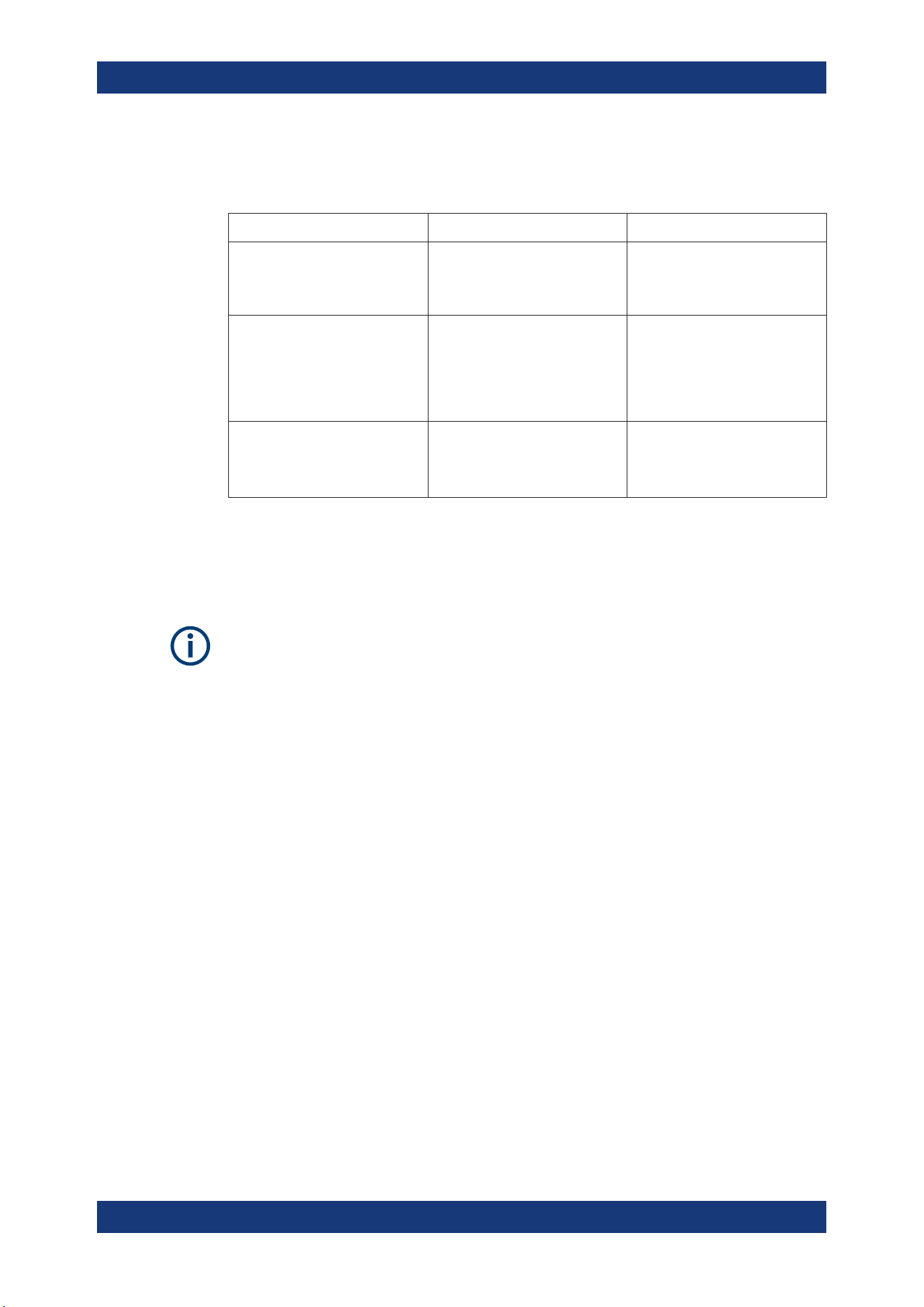
Additional Basics on Remote Control
R&S
®
NGA100
118User Manual 5601.8919.02 ─ 05
A.2.1 Preventing Overlapping Execution
Table A-4: Synchronization using *OPC, *OPC? and *WAI
Command Action Programming the controller
*OPC
Sets the Operation Complete bit
in the ESR after all previous com-
mands have been executed.
●
Setting bit 0 in the ESE
●
Setting bit 5 in the SRE
●
Waiting for service request
(SRQ)
*OPC?
Stops command processing until
1 is returned. It occurs after the
Operation Complete bit has been
set in the ESR. This bit indicates
that the previous setting has been
completed.
Sending *OPC? directly after the
command whose processing
should be terminated before other
commands can be executed.
*WAI
Stops further command process-
ing until all commands have been
executed before *WAI.
Sending *WAI directly after the
command whose processing
should be terminated before other
commands are executed
To prevent an overlapping execution of commands the commands *OPC, *OPC? or
*WAI can be used. All three commands cause a certain action only to be carried out
after the hardware has been set. The controller can be forced to wait for the corre-
sponding action.
The R&S NGA100 series does not support parallel processing of remote commands. If
OPC? returns a "1", the device is able to process new commands.
Command Sequence and Synchronization

List of commands
R&S
®
NGA100
119User Manual 5601.8919.02 ─ 05
List of commands
[SOURce:]CURRent:RANGe...........................................................................................................................85
[SOURce:]CURRent[:LEVel][:IMMediate][:AMPLitude]....................................................................................84
[SOURce:]POWer:PROTection:CLEar.............................................................................................................98
[SOURce:]POWer:PROTection:LEVel............................................................................................................. 97
[SOURce:]POWer:PROTection:TRIPped?.......................................................................................................98
[SOURce:]POWer:PROTection[:STATe]...........................................................................................................98
[SOURce:]VOLTage:PROTection:CLEar..........................................................................................................96
[SOURce:]VOLTage:PROTection:LEVel.......................................................................................................... 96
[SOURce:]VOLTage:PROTection:MODE......................................................................................................... 95
[SOURce:]VOLTage:PROTection:TRIPped?....................................................................................................95
[SOURce:]VOLTage:PROTection[:STATe]........................................................................................................95
[SOURce:]VOLTage:RAMP:DURation...........................................................................................................102
[SOURce:]VOLTage:RAMP[:STATe].............................................................................................................. 102
[SOURce:]VOLTage:SENSe............................................................................................................................ 82
[SOURce:]VOLTage[:LEVel][:IMMediate][:AMPLitude].................................................................................... 83
*CLS.................................................................................................................................................................76
*ESE................................................................................................................................................................ 76
*ESR?.............................................................................................................................................................. 76
*IDN?............................................................................................................................................................... 77
*OPC................................................................................................................................................................77
*OPT?.............................................................................................................................................................. 77
*RST................................................................................................................................................................ 77
*STB?...............................................................................................................................................................77
*WAI.................................................................................................................................................................77
APPLy.............................................................................................................................................................. 85
ARBitrary:CLEar............................................................................................................................................ 100
ARBitrary:DATA............................................................................................................................................. 100
ARBitrary:POINts?.........................................................................................................................................101
ARBitrary:RCL............................................................................................................................................... 100
ARBitrary:REPetitions....................................................................................................................................100
ARBitrary:SAV................................................................................................................................................101
ARBitrary:STARt............................................................................................................................................ 101
ARBitrary:STOP.............................................................................................................................................102
ARBitrary[:STATe].......................................................................................................................................... 101
DATA:DATA?..................................................................................................................................................108
DATA:LIST?................................................................................................................................................... 108
DIAGnostic:SERVice:FWUP..........................................................................................................................108
FUSE:DELay....................................................................................................................................................91
FUSE:LINK...................................................................................................................................................... 91
FUSE:TRIPped?.............................................................................................................................................. 92
FUSE:UNLink...................................................................................................................................................92
FUSE[:STATe].................................................................................................................................................. 92
HCOPy:DATA?...............................................................................................................................................107
HCOPy:SIZE:X?............................................................................................................................................ 107
HCOPy:SIZE:Y?............................................................................................................................................ 107
INSTrument:NSELect...................................................................................................................................... 81
INSTrument[:SELect]....................................................................................................................................... 82

List of commands
R&S
®
NGA100
120User Manual 5601.8919.02 ─ 05
LOG[:STATe].................................................................................................................................................. 107
MEASure[:SCALar]:CURRent[:DC]?............................................................................................................... 99
MEASure[:SCALar]:POWer?........................................................................................................................... 99
MEASure[:SCALar][:VOLTage][:DC]?..............................................................................................................99
OTP:TRIPped?................................................................................................................................................ 89
OUTPut:FUSion...............................................................................................................................................87
OUTPut:GENeral............................................................................................................................................. 87
OUTPut:MODE?.............................................................................................................................................. 88
OUTPut:SELect............................................................................................................................................... 88
OUTPut[:STATe]...............................................................................................................................................86
SYSTem:BEEPer[:IMMediate]......................................................................................................................... 78
SYSTem:COMMunicate:SOCKet:DHCP[:STATe]............................................................................................ 79
SYSTem:COMMunicate:SOCKet:IPADdress?.................................................................................................79
SYSTem:COMMunicate:WLAN:CONNect....................................................................................................... 79
SYSTem:COMMunicate:WLAN:DISConnect................................................................................................... 80
SYSTem:COMMunicate:WLAN:IPADdress?....................................................................................................80
SYSTem:COMMunicate:WLAN:PASSword..................................................................................................... 80
SYSTem:COMMunicate:WLAN:SSID.............................................................................................................. 80
SYSTem:COMMunicate:WLAN[:STATe].......................................................................................................... 80
SYSTem:LOCal................................................................................................................................................78
SYSTem:OPTion?............................................................................................................................................78
SYSTem:REMote............................................................................................................................................. 78
SYSTem:RWLock............................................................................................................................................ 78
SYSTem:TEST:BEEPer................................................................................................................................... 79
SYSTem:TEST:FANCtrl....................................................................................................................................79
SYSTem:TEST:KEYBacklight.......................................................................................................................... 79
SYSTem:TEST:SCReen...................................................................................................................................79
TRIGger:DIRection:DIO<IO>.........................................................................................................................102
TRIGger:IN:ARBitrary:DIO<IO>.....................................................................................................................103
TRIGger:IN:RESPonse:DIO<IO>...................................................................................................................103
TRIGger:IN:SOURce:DIO<IO>......................................................................................................................104
TRIGger:LOGic:DIO<IO>...............................................................................................................................104
TRIGger:MASTer[:STATe].............................................................................................................................. 104
TRIGger:OUT:CONDition:DIO<IO>............................................................................................................... 105
TRIGger:OUT:CRITevent:DIO<IO>................................................................................................................105
TRIGger:OUT:CURRlevel:DIO<IO>...............................................................................................................106
TRIGger:OUT:SOURce:DIO<IO>.................................................................................................................. 106
TRIGger:OUT:VOLTlevel:DIO<IO>................................................................................................................ 106
TRIGger:RCL.................................................................................................................................................106
TRIGger:SAV................................................................................................................................................. 107
TRIGger[:ENABle]:DIO<IO>.......................................................................................................................... 103

Index
R&S
®
NGA100
121User Manual 5601.8919.02 ─ 05
Index
A
Activate channel output ..................................................... 41
Activating fuse ................................................................... 46
B
Bottom panel
Voltage selector .......................................................... 23
Voltage selector label .................................................. 23
C
Calibration certificate ........................................................... 7
Channel display area
Operating mode .......................................................... 30
Channel fusion .................................................................. 44
Clear status
Remote ....................................................................... 76
Command sequence
Remote ....................................................................... 77
Command sequence and synchronization ...................... 117
Controls ............................................................................. 19
Current range setting ........................................................ 42
Customer support ..............................................................27
D
Data logging ...................................................................... 53
Default values
Remote ....................................................................... 77
Digital IO ........................................................................... 50
Display overview ............................................................... 28
Channel display area .................................................. 29
Status bar information ................................................. 28
Documentation overview ..................................................... 7
E
EasyArb .............................................................................54
EasyRamp .........................................................................56
Event status enable register (ESE)
Remote ....................................................................... 76
Event status register (ESR)
Remote ....................................................................... 76
F
Front panel
Display ........................................................................ 19
Function keys .............................................................. 19
Output channels .......................................................... 19
Power key ................................................................... 19
Rotary knob and arrow keys ....................................... 19
USB connector ............................................................ 19
Front panel keys ................................................................30
Output and channel controls ....................................... 31
Fuse .................................................................................. 47
Fuse delay .........................................................................47
Fuse linking ....................................................................... 47
FuseLink ............................................................................47
G
General instrument settings ........................................ 68, 69
Buzzer ......................................................................... 69
Display ........................................................................ 69
Display brightness ...................................................... 69
Key fallback time ......................................................... 69
Keypad ........................................................................ 69
Sound ......................................................................... 69
Getting Started .................................................................... 7
H
Help ................................................................................... 74
I
Identification
Remote ....................................................................... 77
Important notes
Ambient conditions ..................................................... 10
Limits .......................................................................... 12
Mains voltage .............................................................. 11
Measurement categories .............................................11
Symbols ...................................................................... 10
Information ........................................................................ 68
Interfaces and protocols .................................................... 59
Network connection .................................................... 59
M
Maintenance
Cleaning ...................................................................... 26
Internal battery replacement ....................................... 26
Menu ................................................................................. 34
Menu controls ....................................................................30
Message and command structure
Messages .................................................................. 113
SCPI command structure .......................................... 114
Mode
Operation modes ........................................................ 38
N
Navigation controls
Arrow keys .................................................................. 33
Rotary knob ................................................................ 33
Network
LAN ............................................................................. 60
USB ............................................................................ 63
Wireless LAN .............................................................. 62
O
On-screen keyboard ..........................................................36
Open source acknowledgment (OSA) ................................. 8
Operation complete
Remote ....................................................................... 77
Operation modes
Constant current (CC) ................................................. 39
Constant voltage (CV) ................................................ 38

Index
R&S
®
NGA100
122User Manual 5601.8919.02 ─ 05
Options .............................................................................. 69
Identification (remote) ................................................. 77
Install option ................................................................ 69
Installation status ........................................................ 69
Output
Remote sense ............................................................. 43
Output and channel controls ............................................. 31
P
Package contents ..............................................................17
Power derating .................................................................. 37
Protection .......................................................................... 48
Overpower protection (OPP) ...................................... 48
Overvoltage protection (OVP) ..................................... 48
R
Rear panel
AC inlet with fuse holder ............................................. 21
Digital I/O connector ................................................... 21
Ethernet connector ..................................................... 21
USB connector ............................................................ 21
Voltage selector .......................................................... 21
Release notes ..................................................................... 8
Remote control commands
Remote sense commands .......................................... 82
Remote sense function ..................................................... 43
Reset ................................................................................. 70
Reset values
Remote ....................................................................... 77
S
Safety instructions ............................................................... 7
Selecting the channels ...................................................... 40
Setting up the instrument
Bench operation .......................................................... 17
Rack mounting ............................................................ 17
Status bar information
Channel status bar ...................................................... 29
Device status bar ........................................................ 28
Status byte
Remote ................................................................. 76, 77
Store and recall ................................................................. 57
Switching off the instrument .............................................. 23
Switching on the instrument .............................................. 23
System date time .............................................................. 74
System test ....................................................................... 72
T
Tracking function ............................................................... 48
Trying out the instrument
Activating the channels output .................................... 24
Selecting the channels ................................................ 24
Setting the output voltage and Current limit ................ 24
Storing/Recalling of instrument settings ..................... 24
U
Unpacking and checking the instrument ........................... 17
Update ...............................................................................72
User manual ........................................................................ 7
W
Wait
Remote ....................................................................... 77