Data Sheet
Version 23.00
Specifications
R&S®RTH1002
R&S®RTH1004
HANDHELD OSCILLOSCOPE
year

Version 23.00, November 2020
2 Rohde & Schwarz R&S
®
RTH1002, R&S
®
RTH1004 Handheld Oscilloscope
CONTENTS
Definitions ....................................................................................................................................................................... 4
Base unit .......................................................................................................................................................................... 5
Vertical system .................................................................................................................................................................................. 5
Horizontal system .............................................................................................................................................................................. 6
Acquisition system ............................................................................................................................................................................. 6
Trigger system ................................................................................................................................................................................... 7
Waveform measurements .................................................................................................................................................................. 8
Mask testing ...................................................................................................................................................................................... 8
Waveform maths ............................................................................................................................................................................... 8
FFT ................................................................................................................................................................................................... 8
Display characteristics ....................................................................................................................................................................... 9
Protocol and logic .............................................................................................................................................................................. 9
Data logger ........................................................................................................................................................................................ 9
Digital voltmeter (DVM) ...................................................................................................................................................................... 9
Digital multimeter (DMM) ................................................................................................................................................................. 10
Miscellaneous .................................................................................................................................................................................. 11
Inputs and outputs ........................................................................................................................................................................... 11
General data .................................................................................................................................................................. 12
Options .......................................................................................................................................................................... 15
R&S
®
RTH-B1 .................................................................................................................................................................................. 15
Vertical system ............................................................................................................................................................................. 15
Horizontal system......................................................................................................................................................................... 15
Acquisition system ....................................................................................................................................................................... 15
Trigger system ............................................................................................................................................................................. 15
Waveform measurements ............................................................................................................................................................ 16
R&S
®
RTH-K1 .................................................................................................................................................................................. 17
R&S
®
RTH-K2 .................................................................................................................................................................................. 18
R&S
®
RTH-K3 .................................................................................................................................................................................. 19
R&S
®
RTH-K9 .................................................................................................................................................................................. 20
R&S
®
RTH-K10 ................................................................................................................................................................................ 21
R&S
®
RTH-K15 ................................................................................................................................................................................ 22
R&S
®
RTH-K18 ................................................................................................................................................................................ 22
R&S
®
RTH-K19 ................................................................................................................................................................................ 22
R&S
®
RTH-K33 ................................................................................................................................................................................ 23
R&S
®
RTH-K34 ................................................................................................................................................................................ 24
R&S
®
RTH-K38 ................................................................................................................................................................................ 24
R&S
®
RTH-K200 .............................................................................................................................................................................. 25
R&S
®
RTH-K200US .......................................................................................................................................................................... 25
R&S
®
RTH-K201 .............................................................................................................................................................................. 25

Version 23.00, November 2020
Rohde & Schwarz R&S
®
RTH1002, R&S
®
RTH1004 Handheld Oscilloscope 3
Ordering information .................................................................................................................................................... 26
Application packages ....................................................................................................................................................................... 27
Preconfigered two-channel R&S
®
Scope Rider RTH packages ......................................................................................................... 28
Preconfigered four-channel R&S
®
Scope Rider RTH packages ........................................................................................................ 29
Version 23.00, November 2020
4 Rohde & Schwarz R&S
®
RTH1002, R&S
®
RTH1004 Handheld Oscilloscope
Definitions
General
Product data applies under the following conditions:
• Three hours storage at ambient temperature followed by 30 minutes warm-up operation
• Specified environmental conditions met
• Recommended calibration interval adhered to
• All internal automatic adjustments performed, if applicable
Specifications with limits
Represent warranted product performance by means of a range of values for the specified parameter. These specifications are
marked with limiting symbols such as <, ≤, >, ≥, ±, or descriptions such as maximum, limit of, minimum. Compliance is ensured by
testing or is derived from the design. Test limits are narrowed by guard bands to take into account measurement uncertainties, drift
and aging, if applicable.
Non-traceable specifications with limits (n. trc.)
Represent product performance that is specified and tested as described under “Specifications with limits” above. However, product
performance in this case cannot be warranted due to the lack of measuring equipment traceable to national metrology standards. In
this case, measurements are referenced to standards used in the Rohde & Schwarz laboratories.
Specifications without limits
Represent warranted product performance for the specified parameter. These specifications are not specially marked and represent
values with no or negligible deviations from the given value (e.g. dimensions or resolution of a setting parameter). Compliance is
ensured by design.
Typical data (typ.)
Characterizes product performance by means of representative information for the given parameter. When marked with <, > or as a
range, it represents the performance met by approximately 80 % of the instruments at production time. Otherwise, it represents the
mean value.
Nominal values (nom.)
Characterize product performance by means of a representative value for the given parameter (e.g. nominal impedance). In contrast to
typical data, a statistical evaluation does not take place and the parameter is not tested during production.
Measured values (meas.)
Characterize expected product performance by means of measurement results gained from individual samples.
Uncertainties
Represent limits of measurement uncertainty for a given measurand. Uncertainty is defined with a coverage factor of 2 and has been
calculated in line with the rules of the Guide to the Expression of Uncertainty in Measurement (GUM), taking into account
environmental conditions, aging, wear and tear.
Device settings and GUI parameters are designated with the format “parameter: value”.
Non-traceable specifications with limits, typical data as well as nominal and measured values are not warranted by Rohde & Schwarz.
In line with the 3GPP/3GPP2 standard, chip rates are specified in million chips per second (Mcps), whereas bit rates and symbol rates
are specified in billion bits per second (Gbps), million bits per second (Mbps), thousand bits per second (kbps), million symbols per
second (Msps) or thousand symbols per second (ksps), and sample rates are specified in million samples per second (Msample/s).
Gbps, Mcps, Mbps, Msps, kbps, ksps and Msample/s are not SI units.
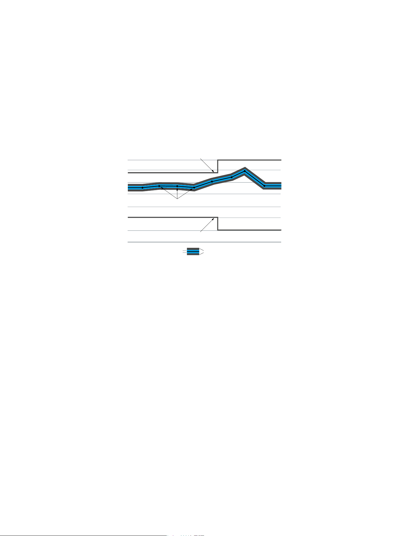
X-axis
Y-axis
Specification limit
Actual values with measurement uncertainty and guard band
Specification limit
Measurement uncertainties Guard band

Version 23.00, November 2020
Rohde & Schwarz R&S
®
RTH1002, R&S
®
RTH1004 Handheld Oscilloscope 5
Base unit
Vertical system
Input channels
R&S
®
RTH1002
2 oscilloscope channels, 1 multimeter
R&S
®
RTH1004
4 oscilloscope channels
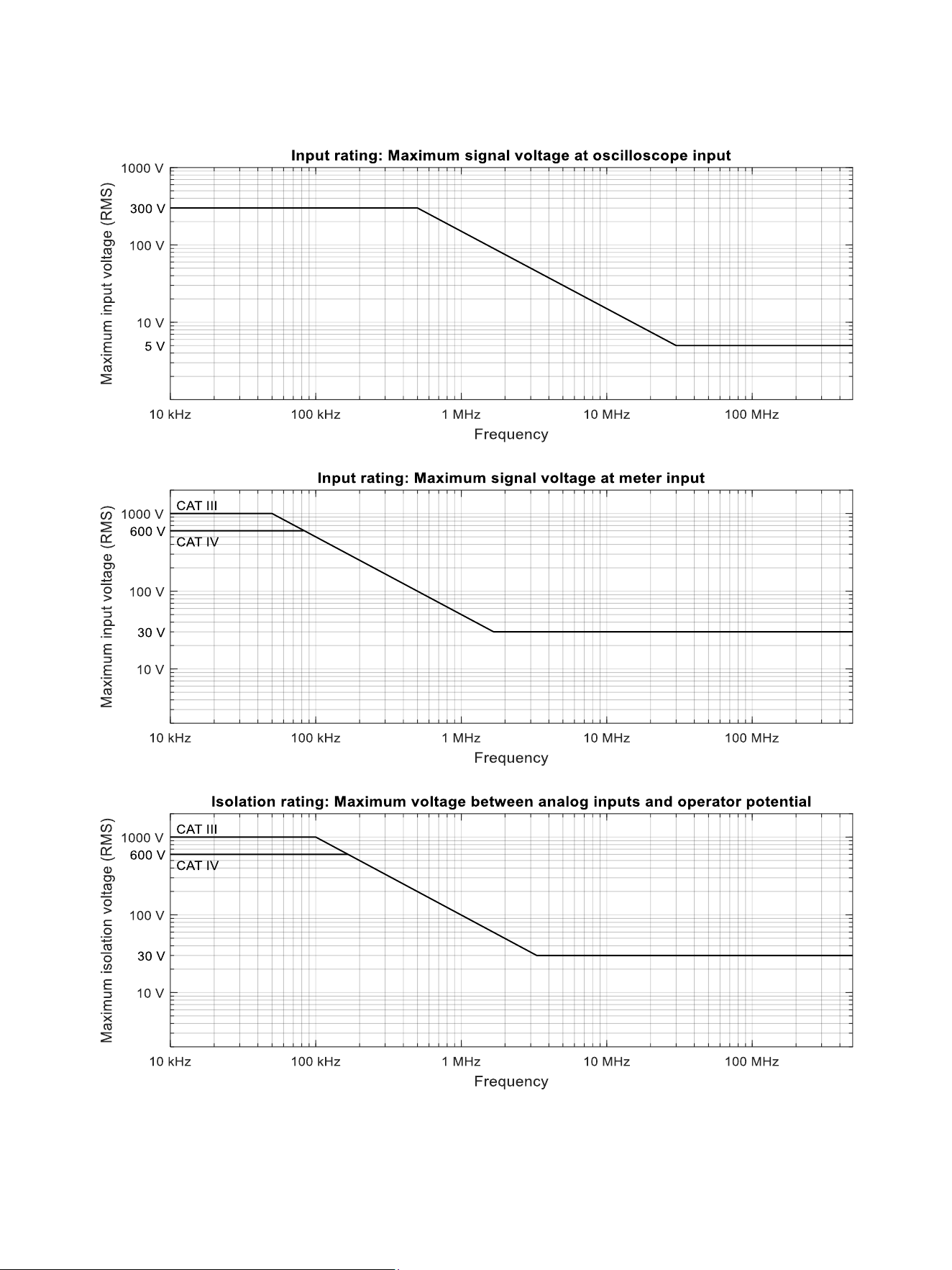
All inputs are floating and fully isolated in line with CAT IV 600 V, CAT III 1000 V safety
rating. See figure regarding isolation rating on page 14.
Input impedance
1 MΩ ± 1 % || 12 pF ± 2 pF (meas.)
Analog bandwidth (–3 dB)
R&S
®
RTH1002 and R&S
®
RTH1004
≥ 60 MHz
R&S
®
RTH1002 with -B221 option and
R&S
®
RTH1004 with -B241 option
≥ 100 MHz
R&S
®
RTH1002 with -B222 option and
R&S
®
RTH1004 with -B242 option
≥ 200 MHz
R&S
®
RTH1002 with -B223 option and
R&S
®
RTH1004 with -B243 option
≥ 350 MHz
1
R&S
®
RTH1002 with -B224 option and
R&S
®
RTH1004 with -B244 option
≥ 500 MHz
1
Measurement of analog bandwidth at input sensitivities ≥ 20 V/div is limited by input
voltage rating versus frequency, see figure “Input rating: Maximum signal voltage at
oscilloscope input” on page 14.
Lower frequency limit (–3 dB) at
AC coupling
< 8 Hz (meas.)
Bandwidth limits
1/2/5/10/20/50/100/200/500 kHz,
1/2/5/10/20/50 MHz
only with R&S
®
RTH-B222, -B242, -B223,
-B243, -B224, -B244 options
100 MHz
only with R&S
®
RTH-B223, -B243, -B224,
-B244 options
200 MHz
Rise time (calculated)
R&S
®
RTH1002 and R&S
®
RTH1004
< 5.8 ns
R&S
®
RTH1002 with -B221 option and
R&S
®
RTH1004 with -B241 option
< 3.5 ns
R&S
®
RTH1002 with -B222 option and
R&S
®
RTH1004 with -B242 option
< 1.75 ns
R&S
®
RTH1002 with -B223 option and
R&S
®
RTH1004 with -B243 option
< 1 ns
2
R&S
®
RTH1002 with -B224 option and
R&S
®
RTH1004 with -B244 option
< 700 ps
2
ADC resolution
10 bit
Vertical resolution of overall system
9 bit; up to 16 bit with high resolution
decimation
DC gain accuracy
offset and position set to zero, after self-alignment
input sensitivity > 5 mV/div
±1.5 %
input sensitivity > 2 mV/div to 5 mV/div
±2 %
input sensitivity 2 mV/div
±2.5 %
Input coupling
DC, AC
Input sensitivity
in steps of 1, 2, 4, 5 in each decade
2 mV/div to 100 V/div
Maximum input voltage
at BNC inputs
CAT IV 300 V (RMS), 424 V (peak),
derates at 20 dB/decade to 5 V (RMS)
above 500 kHz (see figure “Input rating:
Maximum signal voltage at oscilloscope
input” on page 14)
with R&S
®
RT-ZI10 or R&S
®
RT-ZI11 probe
CAT IV 600 V, CAT III 1000 V,
derating in line with probe specification
Position range
±4 div
Invert
R&S
®
RTH1004
CH1, CH2, CH3, CH4
R&S
®
RTH1002
CH1, CH2
Offset range
input sensitivity
≥ 40 V/div
0
≥ 1 V/div to ≤ 20 V/div
±200 V
≤ 500 mV/div
±4 V
1
≥ 200 MHz (meas.) for input sensitivities ≥ 20 V/div.
2
< 1.75 ns (calculated) for input sensitivities ≥ 20 V/div.

Version 23.00, November 2020
6 Rohde & Schwarz R&S
®
RTH1002, R&S
®
RTH1004 Handheld Oscilloscope
Offset accuracy
after self-alignment
±( 0.5 % × |net offset| +
0.1 div × input sensitivity + 1.5 mV )
(net offset = offset – (position × input
sensitivity))
DC measurement accuracy
after adequate suppression of
measurement noise by using high-
resolution sampling mode or waveform
averaging or a combination of both
±( DC gain accuracy ×
|reading – net offset| + offset accuracy )
Channel-to-channel isolation
each channel at same input sensitivity,
input frequency < analog bandwidth
> 40 dB (meas.)
Common mode rejection (CMRR)
DC and AC ≤ 100 kHz
> 100 dB (meas.)
Horizontal system
Timebase range
selectable between 1 ns/div and 500 s/div
Channel deskew
±100 ns
Reference position
10 %, 50 % or 90 % of measurement
display area
Trigger offset range
max.
at least 2 s or 2000 screen widths
at most 100 000 s
min.
right edge of measurement display area
Modes
normal, roll
Timebase accuracy
±10 ppm
Acquisition system
Maximum realtime sampling rate
R&S
®
RTH1004
1 active channel with 5 Gsample/s
2 active channels with 2.5 Gsample/s
4 active channels with 1.25 Gsample/s
R&S
®
RTH1002
1 active channel with 5 Gsample/s
2 active channels with 2.5 Gsample/s
definition: active channel
A channel is active if it is either acquired
or used as a trigger source.
Maximum acquisition length for fast time
bases (less than or equal to 20 ms/div)
1 active analog channel
500 ksample (sample acquisition mode)
250 ksample (high resolution, peak
detect, envelope and average acquisition
modes)
2 active analog channels
250 ksample for each channel (sample
acquisition mode)
125 ksample for each channel (high
resolution, peak detect, envelope and
average acquisition modes)
3 or 4 active analog channels
125 ksample for each channel (sample
acquisition mode)
62.5 ksample for each channel (high
resolution, peak detect, envelope and
average acquisition modes)
Maximum acquisition length for slow time
bases (greater than or equal to 50 ms/div)
1, 2, 3 or 4 active analog channels
125 ksample for each channel (sample
acquisition modes)
62.5 ksample for each channel (high
resolution, peak detect, envelope and
average acquisition modes)
Acquisition modes
sample
first sample in decimation interval
high resolution
average value of samples in decimation
interval
peak detect
largest and smallest sample in decimation
interval
envelope
envelope of acquired waveforms;
for timebases requiring decimation,
peak-detect is used.
average
average of acquired waveforms;
for timebases requiring decimation, high
resolution is used. Number of averaged
waveforms can be power of 2 from 2 to
8192.
Realtime waveform acquisition rate
max.
50 000 waveforms/s

Version 23.00, November 2020
Rohde & Schwarz R&S
®
RTH1002, R&S
®
RTH1004 Handheld Oscilloscope 7
Trigger system
(see also R&S
®
RTH-B1 mixed signal option)
Trigger level
range
±4 div from center of screen
Trigger modes
auto, normal, single
Trigger sources
R&S
®
RTH1004
CH1, CH2, CH3, CH4
R&S
®
RTH1002
CH1, CH2
Hold-off range
time
8 ns to 10 s, fixed and random
events
1 to 1 000 000 000 events
Trigger types
Edge
triggers on specified slope (positive, negative or either) and level
Glitch
triggers on glitches of positive, negative or either polaritiy that are shorter or longer
than specified width
glitch width
800 ps to 5000 s
Width
triggers on positive or negative pulse of specified width; width can be shorter, longer,
inside or outside the interval
pulse width
800 ps to 5000 s
TV/video
triggers on baseband analog progressive and interlaced video signals PAL, NTSC,
SECAM, PAL-M, SDTV and HDTV broadcast standards
(SDTV and HDTV require R&S
®
RTH-K19 option)
trigger events
all fields, odd fields, even fields, all lines,
line number
Pattern
triggers when a logical combination (and, nand, or, nor) of the input channels stays true
for a period of time shorter, longer, inside or outside a specified range
(requires R&S
®
RTH-K19 option)
pattern time
800 ps to 5000 s
State
triggers when a logical combination (and, nand, or, nor) of the input channels stays true
at a slope (positive, negative or either) in one selected channel; state values may be
high (H), low (L) or don’t care (X) (requires R&S
®
RTH-K19 option)
Runt
triggers on pulse of positive, negative or either polarity that crosses one threshold but
fails to cross a second threshold before crossing the first one again; runt pulse width
can be arbitrary, shorter, longer, inside or outside the interval
(requires R&S
®
RTH-K19 option)
runt pulse width
800 ps to 5000 s
Slew rate
triggers when the time required by a signal edge to toggle between user-defined upper
and lower voltage levels is shorter, longer, inside or outside the interval; edge slope
may be positive, negative or either (requires R&S
®
RTH-K19 option)
toggle time
800 ps to 5000 s
Window
triggers when signal enters or exits a specified voltage range; triggers also when signal
stays inside or outside the voltage range for a specified period of time
(requires R&S
®
RTH-K19 option)
window time
800 ps to 5000 s
Data2clock
triggers on setup time and hold time violations between clock and data present on any
two input channels; monitored time interval may be specified by the user with a step
size of 800 ps in the range from –124 ns to 124 ns around a clock edge
(requires R&S
®
RTH-K19 option)
Serial pattern
triggers on serial data pattern up to 32 bit clocked by one input channel; pattern bits
may be high (H), low (L) or don’t care (X); clock edge slope may be positive, negative
or either (requires R&S
®
RTH-K19 option)
max. data rate
< 250 Mbps
Timeout
triggers when signal stays high, low or unchanged for a specified period of time
(requires R&S
®
RTH-K19 option)
timeout
800 ps to 5000 s
Interval
triggers when time between two consecutive edges of same slope (positive or
negative) is shorter, longer inside or outside a specified range
(requires R&S
®
RTH-K19 option)
interval time
800 ps to 5000 s
Protocol
see R&S
®
RTH-K1, R&S
®
RTH-K2, R&S
®
RTH-K3, R&S
®
RTH-K9 and R&S
®
RTH-K10
options

Version 23.00, November 2020
8 Rohde & Schwarz R&S
®
RTH1002, R&S
®
RTH1004 Handheld Oscilloscope
Waveform measurements
(see also R&S
®
RTH-B1 mixed signal option)
Automatic measurements
total number of active measurements
4
sources
R&S
®
RTH1004
CH1, CH2, CH3, CH4, math
R&S
®
RTH1002
CH1, CH2, math
time based measurements
period, frequency, rise time, fall time,
positive pulse width, negative pulse width,
positive duty cycle, negative duty cycle,
delay, phase
amplitude based measurements
mean value, RMS value, crest factor,
standard deviation, minimum, maximum,
peak-to-peak, base level, top level,
amplitude, area, overshoot, preshoot, AC,
DC, AC+DC
count based measurements
count positive pulses, count negative
pulses, count rising edges, count falling
edges
power based measurements
active power, apparent power, reactive
power, power factor, V
PWM
, f
PWM
, V/f
PWM
Cursor measurements
sources
analog channels, math and reference
waveforms
vertical
2 cursors showing time, time difference
and inverse time difference (frequency)
horizontal
2 cursors showing voltage and voltage
difference
tracking
vertical cursor additionally showing
voltage and voltage difference of selected
waveform
measure
defines gate for automatic measurements
Mask testing
Sources
R&S
®
RTH1004
CH1, CH2, CH3, CH4, math
R&S
®
RTH1002
CH1, CH2, math
Mask definition
tolerance tube based on analog input
waveform or math waveform
Number of simultaneous mask tests
up to 5
Actions on violation
none, beep, stop
History behavior
requires R&S
®
RTH-K15 option
store all
Waveform maths
Number of math waveforms
1
Functions
addition, subtraction, multiplication,
square, absolute value, inverse
Sources
R&S
®
RTH1004
CH1, CH2, CH3, CH4
R&S
®
RTH1002
CH1, CH2
FFT
Number of simultaneous spectra
1 (always on selected channel)
Sources
R&S
®
RTH1004
CH1, CH2, CH3, CH4
R&S
®
RTH1002
CH1, CH2
FFT sizes
64 ksample or 8 ksample
Sampling frequency
equal to sampling rate of current
horizontal scale for FFT size of 64
ksample;
equal to 1/8
th
of sampling rate of current
horizontal scale for FFT size of 8 ksample
Window types
rectangular, flat-top, Hamming, Hann,
Blackman
Channel bandwidth
same as bandwidth limits in vertical
system;
additionally accessible over FFT menu
X-axis scaling
linear or logarithmic

Version 23.00, November 2020
Rohde & Schwarz R&S
®
RTH1002, R&S
®
RTH1004 Handheld Oscilloscope 9
Display characteristics
Diagram types
Yt, XY, zoom, FFT
XY mode
parallel display of XY diagram, Xt and Yt
Zoom
horizontal zoom with overview bar graph showing location of zoom window
Interpolation
sin(x)/x
Persistence
50 ms to 10 s; infinite
Reference signals
up to 1 reference signal
Protocol and logic
Bus trigger and decode
number of bus signals
1
bus types
R&S
®
RTH-K1 option
SPI, I
2
C
R&S
®
RTH-K2 option
UART
R&S
®
RTH-K3 option
CAN, LIN
R&S
®
RTH-K9 option
CAN-FD
R&S
®
RTH-K10 option
SENT
display types
decoded bus, logical signal, event table
position and size
size and position on screen selectable
data format of decoded bus
hex, decimal, binary
Data logger
Data acquisition method
roll mode recording of measurement
results
Number of simultaneous logging channels
4
Sources
R&S
®
RTH1004
oscilloscope mode
up to 4 waveform measurements
digital voltmeter mode
up to 4 digital voltmeter measurements
counter mode (R&S
®
RTH-K33 option)
up to 2 counter measurements
R&S
®
RTH1002
oscilloscope mode
up to 4 waveform measurements
multimeter mode
multimeter measurement
counter mode (R&S
®
RTH-K33 option)
up to 2 counter measurements
Timebase range
selectable between 5 s/div and 4 days/div
Measurement speed
1/2/5 measurements/s
Memory depth
2 Msample per logging channel
Slot memory
internal memory for up to 10 sets of data
logger results; slots results can be reset,
loaded and exported.
Digital voltmeter (DVM)
Sources
R&S
®
RTH1004
CH1, CH2, CH3, CH4
Measurements
voltage
DC, AC, AC+DC
with indication of max., min. and average
Number of active measurements
4
Maximum resolution
999 counts, 3 digits

Version 23.00, November 2020
10 Rohde & Schwarz R&S
®
RTH1002, R&S
®
RTH1004 Handheld Oscilloscope
Digital multimeter (DMM)
Sources
R&S
®
RTH1002
multimeter, 4 mm banana inputs, fully
isolated from scope inputs, interfaces and
ground
Measurements
voltage
DC, AC, AC+DC
current
with current clamp or shunt
resistance
continuity test
diode test
temperature
resistance measurement with PT100 or
PT500 platinum sensors
(recommended accessory R&S
®
RT-ZA12
PT100 temperature probe)
frequency
capacitance
Number of active measurements
1
Maximum resolution
10000 counts, 4 digits
Input impedance
(voltage DC, AC, AC+DC)
1 V, 10 V
11.11 MΩ (nom.)
100 V
10.10 MΩ (nom.)
1000 V
10.01 MΩ (nom.)
Input capacitance
< 100 pF
Common mode rejection ratio (CMRR)
DC and 50 Hz/60 Hz ± 0.1 %
> 100 dB (meas.)
Normal mode rejection ratio (NMRR)
50 Hz/60 Hz ± 0.1 %
> 60 dB (meas.)
Maximum input voltage
CAT III 1000 V (RMS), 1414 V (peak),
CAT IV 600 V (RMS), 849 V (peak),
derates at 20 dB/decade above 50 kHz
(see figure “Input rating: Maximum signal
voltage at meter input” on page 14)
Specified accuracy temperature range
rated accuracy applies after 1 h
stabilization
+23 °C ± 5 °C
Temperature coefficient
from 0 °C to +18 °C or +28 °C to +50 °C
0.1 × specified accuracy/°C
Voltage ranges
10 % overrange except of 1000 V range
1.0000 V, 10.000 V, 100.00 V, 1000.0 V
DC accuracy
1 V
±(0.05 % + 0.05 % of range)
10 V, 100 V
±(0.05 % + 0.03 % of range)
1000 V
±(0.08 % + 0.03 % of range)
AC accuracy (AC coupling)
1 V, 10 V, 100 V
20 Hz to 20 kHz
±(0.2 % + 0.05 % of range)
20 kHz to 100 kHz
±(0.5 % + 0.05 % of range)
1000 V
20 Hz to 10 kHz
±(0.2 % + 0.05 % of range)
Resistance ranges
10 % overrange
1.0000 kΩ, 10.000 kΩ, 100.00 kΩ,
1.0000 MΩ, 10.000 MΩ, 100.00 MΩ
Resistance accuracy
1 kΩ, 10 kΩ, 100 kΩ, 1 MΩ
±(0.08 % + 0.03 % of range)
10 MΩ
±(0.2 % + 0.05 % of range)
100 MΩ
±(1.5 % + 0.1 % of range)
Resistance test currents
1 kΩ
1.004 mA (nom.)
10 kΩ
101.3 µA (nom.)
100 kΩ
10.13 µA (nom.)
1 MΩ
1.003 µA (nom.)
10 MΩ
100.3 nA (nom.)
100 MΩ
100.3 nA || 11.11 MΩ (nom.)
Continuity range
test current 1.004 mA (nom.),
continuous beep when resistance < 10 Ω
1.0000 kΩ
Continuity accuracy
±(0.1 % + 0.5 Ω)
Diode test ranges
test current 1.004 mA (nom.)
3.000 V
Diode test accuracy
±(0.1 % + 3 mV)
Capacity ranges
10 % overrange
10.000 nF, 100.00 nF, 1.0000 µF,
10.000 µF, 100.00 µF, 1.0000 mF,
10.000 mF
Capacity accuracy
±(1 % + 0.05 % of range)
Temperature (calculated)
with linearization for platinum sensors,
in line with EN 60751,
range from –200 °C to +850 °C
±(0.13 % + sensor tolerance + 1 °C)
Frequency ranges
1000.0 Hz, 10.000 kHz, 100.00 kHz,
250.0 kHz
Frequency accuracy
±0.005 %

Version 23.00, November 2020
Rohde & Schwarz R&S
®
RTH1002, R&S
®
RTH1004 Handheld Oscilloscope 11
Miscellaneous
Save/recall
device settings
save and recall on micro SD card or
USB drive
reference waveforms
save and recall on micro SD card or
USB drive
screenshots
save on micro SD card or USB drive
logger records
export to USB drive
configurable fast setting slots
8 slots, F1 to F8 to easily activate
preconfigured settings with a single
keystroke
Screenshot
selectable file formats
png, jpg, bmp, tif
screenshot modes
standard, inverse, black and white
Instrument security
User data and settings are stored on
removable micro SD card only.
Menu languages
available menu languages:
• English
• German
• French
• Russian
• Simplified Chinese
• Traditional Chinese
• Japanese
• Spanish
• Italian
• Portuguese
• Korean
• Czech
• Polish
Help
online help on the instrument
available language:
• English
Inputs and outputs
Channel inputs
R&S
®
RTH1004
4 BNC oscilloscope inputs
R&S
®
RTH1002
2 BNC oscilloscope inputs,
2 banana jack meter inputs (4-mm type)
Probe compensation output
signal shape
rectangle
V
low
= 0 V, V
high
= 1 V
amplitude 1 V (peak-to-peak) ± 5 %
frequency
1 kHz ± 5 %
USB host interface
1 port, type A plug, USB 2.0,
memory sticks only; FAT32 formatting
required
USB device port
1 port, mini USB-B, remote control only
LAN interface
RJ-45 connector, supports 10/100BASE-T
Logic probe input
8 logic channels, see R&S
®
RTH-B1 option
External trigger input
R&S
®
RTH1002
Meter input can also be used as external
trigger input.
Security slot
for standard Kensington style lock
SD card slot
type
micro SD card slot, memory cards only
capacity
SDHC, min. 4 Gbyte, max. 32 Gbyte

Version 23.00, November 2020
12 Rohde & Schwarz R&S
®
RTH1002, R&S
®
RTH1004 Handheld Oscilloscope
General data
Display
Type
7.0'' LC TFT color display
Resolution
800 × 480 pixel (WVGA)
Temperature
Temperature loading
operating temperature
battery only
0 °C to +50 °C
power adapter
0 °C to +40 °C
storage temperature
–20 °C to +50 °C
Climatic loading
+25 °C/+55 °C at 95 % rel. humidity
cyclic, in line with IEC 60068-2-30
Altitude
Operating
CAT IV 600 V, CAT III 1000 V
up to 2000 m above sea level
CAT III 600 V, CAT II 1000 V
up to 3000 m above sea level
Nonoperating
up to 4600 m above sea level
Mechanical resistance
IP rating
IP51, in line with IEC 60529
Vibration
sinusoidal
5 Hz to 150 Hz, max. 1.8 g at 55 Hz,
0.5 g from 55 Hz to 150 Hz,
in line with EN 60068-2-6;
MIL-PRF-28800F, 4.5.5.3.2, class 3
random
8 Hz to 650 Hz,
acceleration 1.9 g (RMS),
in line with EN 60068-2-64;
MIL-PRF-28800F, 4.5.5.3.1 random
vibration, class 3
Shock
40 g shock spectrum,
in line with MIL-STD-810E,
method no. 516.4, procedure I;
MIL-PRF-28800F, 4.5.5.4.1,
functional shock, 30 g, 11 ms, halfsine
EMC
RF emission
in line with CISPR 11/EN 55011 group 1
class A (for a shielded test setup);
the instrument complies with the emission
requirements stipulated by EN 55011,
EN 61326-1 and EN 61326-2-1 class A,
making the instrument suitable for use in
industrial environments.
Immunity
in line with IEC/EN 61326-1 table 2,
immunity test requirements for industrial
environments
3
Certifications
VDE,
C
CSA
US,
KC
Calibration interval
1 year
3
Test criterion is displayed noise level within ±2.5 div for input sensitivity of 200 mV/div.

Version 23.00, November 2020
Rohde & Schwarz R&S
®
RTH1002, R&S
®
RTH1004 Handheld Oscilloscope 13
Safety
in line with
• IEC/EN/DIN EN 61010-1,
• IEC/EN/DIN EN 61010-2-030,
• UL/CSA 61010-1,
• UL/CSA 61010-2-030,
• IEC/EN/DIN EN 61010-2-033 (R&S
®
RTH1002),
• UL/CSA 61010-2-033 (R&S
®
RTH1002)
Battery/power supply
Battery data
lithium-ion rechargeable smart battery
operating time
approx. 4 h
charging time
approx. 4 h while instrument is switched
off
capacity
72 Wh
voltage
11.25 V
Power adapter
input
100 V to 240 V at 50 Hz to 60 Hz, 1.5 A
output
+15 V DC, 4.0 A
Mechanical data
Dimensions
W × H × D
201 mm × 293 mm × 74 mm
(7.91 in × 11.54 in × 2.91 in)
Weight
with battery
2.4 kg (5.3 lb) (nom.)
Version 23.00, November 2020
14 Rohde & Schwarz R&S
®
RTH1002, R&S
®
RTH1004 Handheld Oscilloscope

Version 23.00, November 2020
Rohde & Schwarz R&S
®
RTH1002, R&S
®
RTH1004 Handheld Oscilloscope 15
Options
R&S
®
RTH-B1
Mixed signal option, additional 8 logic channels
Vertical system
Input channels
8 logic channels (from D0 to D7)
Input impedance
100 kΩ ± 2 % || ~4 pF (meas.) at probe
tips
Maximum input frequency
signal with minimum input voltage swing
and hysteresis setting: normal
250 MHz (meas.)
Maximum input voltage
±40 V (peak)
Minimum input voltage swing
500 mV (peak-to-peak) (meas.)
Threshold groups
from D0 to D3, D4 to D7
Threshold level
range
±8 V in 25 mV steps
predefined
CMOS 5.0 V, CMOS 3.3 V, CMOS 2.5 V,
TTL, ECL, PECL, LVPECL
Threshold accuracy
±(100 mV + 3 % of threshold setting)
Comparator hysteresis
normal, robust, maximum
Horizontal system
Channel deskew
range for each channel
±100 ns
Channel-to-channel skew
< 2 ns (meas.)
Acquisition system
Maximum realtime sampling rate
1.25 Gsample/s on each channel
Maximum acquisition length for fast time
bases (less than or equal to 20 ms/div)
125 ksample for each channel
Maximum acquisition length for slow time
bases (greater than or equal to 50 ms/div)
125 ksample for each channel (sample
acquisition mode of analog channels even
if no analog channel is active)
62.5 ksample for each channel (high
resolution, peak detect, envelope and
average acquisition modes of analog
channels even if no analog channel is
active)
Trigger system
Trigger level
range
±4 div from center of screen
Trigger modes
auto, normal, single
Trigger sources
R&S
®
RTH1004
logic channels from D0 to D7
CH1, CH2, CH3, CH4
R&S
®
RTH1002
logic channels from D0 to D7
CH1, CH2
Hold off range
time
8 ns to 10 s, fixed and random
events
1 to 1 000 000 000 events

Version 23.00, November 2020
16 Rohde & Schwarz R&S
®
RTH1002, R&S
®
RTH1004 Handheld Oscilloscope
Trigger types
Edge
triggers on specified slope (positive, negative or either) and level
Glitch
triggers on glitches of positive, negative or either polaritiy that are shorter or longer
than specified width
glitch width
800 ps to 5000 s (CH1, CH2, CH3, CH4)
800 ps to 5000 s (D0 to D7)
Width
triggers on positive or negative pulse of specified width; width can be shorter, longer,
inside or outside the interval
pulse width
800 ps to 5000 s (CH1, CH2, CH3, CH4)
800 ps to 5000 s (D0 to D7)
Pattern
triggers when a logical combination (and, nand, or, nor) of the input channels stays true
for a period of time shorter, longer, inside or outside a specified range
(requires R&S
®
RTH-K19 option)
pattern time
800 ps to 5000 s (CH1, CH2, CH3, CH4)
800 ps to 5000 s (D0 to D7)
State
triggers when a logical combination (and, nand, or, nor) of the input channels stays true
at a slope (positive, negative or either) in one selected channel; state values may be
high (H), low (L) or don’t care (X) (requires R&S
®
RTH-K19 option)
Data2clock
triggers on setup time and hold time violations between clock and data present on any
two input channels; monitored time interval may be specified by the user with a step
size of 800 ps in the range from –124 ns to 124 ns around a clock edge
(requires R&S
®
RTH-K19 option)
Serial pattern
triggers on serial data pattern up to 32 bit clocked by one input channel; pattern bits
may be high (H), low (L) or don’t care (X); clock edge slope may be positive, negative
or either (requires R&S
®
RTH-K19 option)
max. data rate
< 250 Mbps
Timeout
triggers when signal stays high, low or unchanged for a specified period of time
(requires R&S
®
RTH-K19 option)
timeout
800 ps to 5000 s (CH1, CH2, CH3, CH4)
800 ps to 5000 s (D0 to D7)
Interval
triggers when time between two consecutive edges of same slope (positive or
negative) is shorter, longer inside or outside a specified range
(requires R&S
®
RTH-K19 option)
interval time
800 ps to 5000 s (CH1, CH2, CH3, CH4)
800 ps to 5000 s (D0 to D7)
Protocol
see R&S
®
RTH-K1, R&S
®
RTH-K2, R&S
®
RTH-K3, R&S
®
RTH-K9 and R&S
®
RTH-K10
options
Waveform measurements
Automatic measurements on
total number of active measurements
4
sources
logic channels from D0 to D7
time based measurements
period, frequency, positive pulse width,
negative pulse width, positive duty cycle,
negative duty cycle, delay, phase
amplitude based measurements
mean value
count based measurements
count positive pulses, count negative
pulses, count rising edges, count falling
edges
Cursor measurements
sources
logic channels from D0 to D7
vertical
2 cursors showing time, time difference
and inverse time difference (frequency)
tracking
vertical cursor additionally showing logic
level and logic level difference of selected
channel
measure
defines gate for automatic measurements

Version 23.00, November 2020
Rohde & Schwarz R&S
®
RTH1002, R&S
®
RTH1004 Handheld Oscilloscope 17
R&S
®
RTH-K1
I
2
C serial triggering and decoding
Protocol configuration
bit rate
up to 3.4 Mbps (auto-detected)
auto threshold setup
assisted threshold configuration for I
2
C
triggering and decoding (software)
device list
associate frame address with symbolic ID
(software)
Trigger
source (clock and data)
any input channel or logical channel
trigger event setup
start, stop, restart, missing ACK, address,
data, address + data
address setup
7 bit or 10 bit address (value in hex or
binary); read, write or either; condition =, ≠
data setup
data pattern up to 8 byte (hex or binary);
condition =, ≠; >, <; offset within frame in
range from 0 byte to 4095 byte
Decode
source (clock and data)
any input channel, logical channel
display type
decoded bus, tabulated list
color coding
frame, start/restart, address (r/w), data,
ACK/NACK, stop, error
address and data format
hex, decimal, octal, binary, ASCII;
symbolic names for user-defined subset
of addresses (software)
SPI serial triggering and decoding
Protocol configuration
type
2-wire, 3-wire and 4-wire SPI
bit rate
up to 50 Mbps (auto-detected)
bit order
LSB first, MSB first
word size
4/8/12/16/20/24/28/32 bit
frame condition
SS, timeout
polarity (MOSI, MISO, SS)
active high, active low
slope (CLK)
rising edge, falling edge
auto threshold setup
assisted threshold configuration for SPI
triggering and decoding (software)
Trigger
source (MOSI, MISO, SS, CLK)
any input channel or logical channel
trigger event setup
start of frame, end of frame, MOSI, MISO
data setup
data pattern up to 32 bit (hex or binary);
condition =, ≠; offset within frame in range
from 0 to 4095 bit
Decode
source (MOSI, MISO, SS, CLK)
any input channel, logical channel
display type
decoded bus, tabulated list
color coding
frame start, frame stop, word, error
data format
hex, decimal, octal, binary, ASCII
(software)

Version 23.00, November 2020
18 Rohde & Schwarz R&S
®
RTH1002, R&S
®
RTH1004 Handheld Oscilloscope
R&S
®
RTH-K2
UART/RS-232/RS-422/RS-485 serial triggering and decoding
Protocol configuration
bit rate
300 bps to 20 Mbps
signal polarity
idle low, idle high
number of bits
5 bit to 9 bit
bit order
LSB first, MSB first
parity
odd, even, none
stop bits
1, 1.5 or 2
end of packet
timeout, none
auto threshold setup
assisted threshold configuration for UART
triggering and decoding (software)
Trigger
source
any input channel or logical channel
trigger event setup
start bit, packet start, data, parity error,
stop error, break condition
data setup
data pattern (hex, decimal, octal, binary or
ASCII); condition =, ≠; >, <; offset within
packet in range 0 to 4095 words
Decode
source
any input channel, logical channel
display type
decoded bus, tabulated list
color coding
start, data payload, parity, stop, start
error, parity error, stop error
data format
hex, decimal, octal, binary, ASCII

Version 23.00, November 2020
Rohde & Schwarz R&S
®
RTH1002, R&S
®
RTH1004 Handheld Oscilloscope 19
R&S
®
RTH-K3
CAN triggering and decoding
Protocol configuration
signal type
CAN_H, CAN_L
bit rate
standard bit rate (10/20/33.3/50/83.3/
100/125/250/500/1000 kbps) or user-
defined bit rate in range from 10 kbps to
1 Mbps
sampling point
10 % to 95 % within bit period
device list
associate frame identifier with symbolic
ID, load DBC file content
auto threshold setup
assisted threshold configuration for CAN
triggering and decoding (software)
Trigger
source
any input channel or logical channel
trigger event setup
start of frame, end of frame, frame type,
identifier, identifier + data, error condition
(any combination of CRC error, bit stuffing
error, form error and ACK error)
identifier setup
frame type (data, remote or both),
identifier type (11 bit or 29 bit); condition
=, ≠; identifier selectable from label list
data setup
data pattern up to 8 byte (hex or binary);
condition =, ≠
Decode
source
any input channel, logical channel
display type
decoded bus, tabulated list
color coding
start of frame, identifier, DLC, data
payload, CRC, end of frame, error frame,
overload frame, CRC error
data format
hex, decimal, octal, binary, ASCII,
symbolic
LIN triggering and decoding
Protocol configuration
version
1.3, 2.x or SAE J602; mixed traffic is
supported
bit rate
standard bit rate (1.2/2.4/4.8/9.6/10.417/
19.2 kbps) or user-defined bit rate in
range from 1 kbps to 20 kbps
signal polarity
idle low, idle high
device list
associate frame address with symbolic ID
(software)
auto threshold setup
assisted threshold configuration for LIN
triggering and decoding (software)
Trigger
source
any input channel or logical channel
trigger event setup
start of frame (sync break), identifier,
identifier + data, wakeup frame, error
condition (any combination of checksum
error, parity error and sync field error)
identifier setup
range from 0d to 63d; condition =, ≠;
identifier selectable from label list
data setup
data pattern up to 8 byte (hex or binary);
condition =, ≠
Decode
source
any input channel, logical channel
display type
decoded bus, tabulated list
color coding
frame, frame identifier, parity, data
payload, checksum, error condition
data format
hex, decimal, octal, binary, ASCII

Version 23.00, November 2020
20 Rohde & Schwarz R&S
®
RTH1002, R&S
®
RTH1004 Handheld Oscilloscope
R&S
®
RTH-K9
CAN-FD triggering and decoding (requires option R&S
®
RTH-K3 as basis)
Protocol configuration
signal polarity
CAN_H, CAN_L
standard
ISO, non-ISO (Bosch)
bit rate
arbitration rate
standard bit rate (10/20/33.3/50/83.3/
100/125/250/500/1000 kbps) or user-
defined bit rate in range from 10 kbps to
1 Mbps
data rate
standard bit rate (10/20/33.3/50/83.3/
100/125/250/500 kbps;
1/1.5/2/4/6/8/10/12/14/15 Mbps) or user-
defined bit rate in range from 10 kbps to
15 Mbps
sampling point
10 % to 95 % within bit period;
independent settings for arbitration phase
and data phase
device list
associate frame identifier with symbolic
ID, load DBC file content
auto threshold setup
assisted threshold configuration for CAN
triggering and decoding (software)
Trigger
source
any input channel or logical channel
trigger event setup
start of frame, end of frame, frame type,
identifier, identifier + data, error condition
(any combination of CRC error, bit stuffing
error, form error, stuff count error and
ACK error)
identifier setup
frame type (data, remote or both),
identifier type (11 bit or 29 bit); condition
=, ≠; identifier selectable from label list
FD bits
FDF, BRS and ESI (0, 1, X)
data setup
data pattern up to 8 byte (hex or binary);
condition =, ≠
Decode
source
any input channel, logical channel
display type
decoded bus, tabulated list
color coding
start of frame, identifier, FD bits, DLC,
data payload, stuff count, CRC, end of
frame, error frame, overload frame, CRC
error
data format
hex, decimal, octal, binary, ASCII,
symbolic

Version 23.00, November 2020
Rohde & Schwarz R&S
®
RTH1002, R&S
®
RTH1004 Handheld Oscilloscope 21
R&S
®
RTH-K10
SENT triggering and decoding
Protocol configuration
signal polarity
idle low, idle high
clock period (clock tick)
1 µs to 100 µs
clock tolerance
0 % to 25 %
data nibbles
1 to 6
serial message type
none, short serial message and enhanced
serial message
CRC version
legacy (Feb 2008) and v2010, v2016
(latest)
CRC calculation
SAE J2716 standard and TLE 4998X
pause pulse
no, yes, for constant frame length
frame length in clock ticks (applicable only
when pause pulse = constant frame
length)
104 to 922
auto threshold setup
assisted threshold configuration for SENT
triggering and decoding (software)
Trigger
source
any input channel or logical channel
trigger event setup
calibration or sync, transmission
sequence status, transmission sequence
status + data, serial message identifier,
serial message identifier + data, error
condition (any combination of calibration
pulse error, pulse period error,
transmission sequence CRC error, serial
message CRC error and irregular frame
length error)
transmission sequence status nibble
setup
from 0 to F, condition =, ≠
transmission sequence data nibbles setup
each nibble value from 0 to F,
condition =, ≠
serial message identifier setup
from 00 to FF, condition =, ≠;
identifier selectable from label list
serial message identifier type setup
(applicable only when the serial protocol =
enhanced serial message in protocol
configuration)
4 bit and 8 bit
serial message data setup
00 to FF (short serial message)
000 to FFF (enhanced serial message
with 8 bit ID)
0000 to FFFF (enhanced serial message
with 4 bit ID)
Decode
source
any input channel, logical channel
display type
decoded bus, tabulated list
color coding
transmission sequence:
sync/calibration, status, data bits, CRC,
pause pulse, calibration pulse error, pulse
period error, irregular frame length error
and CRC error;
serial message:
identifier, data, CRC, CRC error
data format
hex, decimal, octal, binary, ASCII,
symbolic

Version 23.00, November 2020
22 Rohde & Schwarz R&S
®
RTH1002, R&S
®
RTH1004 Handheld Oscilloscope
R&S
®
RTH-K15
History and segmented memory
Memory segmentation
function
Provides an adjustable number of memory segments for the acquisition.
Segmentation is active on all analog and logic channels and protocol
decoding.
Combinations with zoom and math functions are supported, but reduce the
effectively used number of segments.
maximum record length
per channel (analog
channels in sample
acquisition mode)
segments
1 active
analog
channel
(sample)
2 active
analog
channels
(sample)
3 or 4
active
analog
channels
(sample)
digital
channels
(sample)
serial
channel
(protocol
memory in
byte)
5000
10k
5k
2.5k
2.5k
5.12k
1000
50k
25k
12.5k
12.5k
25.6k
100
500k
250k
125k
125k
256k
total memory per
channel
50M
25M
12.5M
12.5M
25.6M
maximum record length
per channel (analog
channels in high
resolution, peak detect,
envelope and average
acquisition modes)
segments
1 active
analog
channel
(sample)
2 active
analog
channels
(sample)
3 or 4
active
analog
channels
(sample)
digital
channels
(sample)
serial
channel
(protocol
memory in
byte)
5000
5k
2.5k
1.25k
1.25k
5.12k
1000
25k
12.5k
6.25k
6.25k
25.6k
100
250k
125k
62.5k
62.5k
256k
total memory per
channel
25M
12.5M
6.25M
6.25M
25.6M
History mode
function
If active, the history mode provides access to past acquisitions in the
segmented memory.
timestamp resolution
1.6 ps
time format
relative, absolute
history player
replays the recorded waveforms; start and stop waveform can be set;
repetition possible
R&S
®
RTH-K18
Spectrum analysis
Spectrum
R&S
®
RTH1004
CH1, CH2, CH3, CH4
R&S
®
RTH1002
CH1, CH2
scaling x-axis
linear or logarithmic frequency axis
scaling y-axis
dBm, dBV, dBA
setup parameters
center frequency and span (linear frequency axis),
start and stop frequency (logarithmic frequency axis),
resolution bandwidth, vertical scale
span
1 kHz up to instrument bandwidth
resolution bandwidth
span/10 ≥ RBW ≥ span/1000
window types
flat-top, Hann, Hamming, Blackman, rectangular
trace types
normal, max. hold, min. hold, average
Marker
peak marker search
parameters: threshold, excursion, distance
markers on peak
up to 15
sources
any spectrum trace
marker values
absolute frequency and amplitude level or
frequency and amplitude level relative to reference marker
Cursor
sources
any spectrum trace
cursor values
absolute frequency and amplitude level of cursor 1 and
absolute frequency and amplitude level of cursor 2 or
frequency and amplitude level of cursor 2 relative to cursor 1
cursor functions
track scaling, coupling, set to screen
R&S
®
RTH-K19
Advanced triggering
Additional trigger types:
TV/video: SDTV and HDTV broadcast standards; pattern, state, runt, slew rate, window, data2clock, serial pattern, timeout and
interval. For more details see Trigger system.

Version 23.00, November 2020
Rohde & Schwarz R&S
®
RTH1002, R&S
®
RTH1004 Handheld Oscilloscope 23
R&S
®
RTH-K33
Frequency counter
Sources
R&S
®
RTH1004
CH1, CH2, CH3, CH4
R&S
®
RTH1002
CH1, CH2
Number of counters
2
Number of measurements
up to 2 using internal clock as reference;
1 using external signal to second counter
as reference
Frequency range
R&S
®
RTH1002 and R&S
®
RTH1004
10 Hz up to 66 MHz
R&S
®
RTH1002 with -B221 option and
R&S
®
RTH1004 with -B241 option
10 Hz up to 110 MHz
R&S
®
RTH1002 with -B222 option and
R&S
®
RTH1004 with -B242 option
10 Hz up to 220 MHz
R&S
®
RTH1002 with -B223 option and
R&S
®
RTH1004 with -B243 option
10 Hz up to 385 MHz
R&S
®
RTH1002 with -B224 option and
R&S
®
RTH1004 with -B244 option
10 Hz up to 550 MHz
Long term statistics
max., min. and average since (re-)start;
max. and min. are time stamped with a
resolution of 1 s.
Precision
(measurement accuracy must also take
reference clock accuracy into account)
f ≥ 10 kHz
7 digits (meas.)
1 kHz ≤ f < 10 kHz
6 digits (meas.)
100 Hz ≤ f < 1 kHz
4 digits (meas.)
10 Hz ≤ f < 100 Hz
3 digits (meas.)
(greater precision can be achieved by
observing the long term average)
Coupling
Measured channels are automatically
switched to AC coupling.

Version 23.00, November 2020
24 Rohde & Schwarz R&S
®
RTH1002, R&S
®
RTH1004 Handheld Oscilloscope
R&S
®
RTH-K34
Harmonic analysis
Harmonics
R&S
®
RTH1004
CH1, CH2, CH3, CH4
R&S
®
RTH1002
CH1, CH2
setup parameters
fundamental frequency, scale
scaling
linear (percent) or logarithmic (dB)
fundamental frequency
10 Hz to 1 MHz
harmonics
up to 64 harmonics
statistic
current, max., min.
limits
predefined limits or user defined
Display
bar graph
up to 64 harmonics on one screen
displayed harmonics
all harmonics,
even harmonics,
odd harmonics,
odd and multiple of 3,
odd and not multiple of 3 or
user defined
Measurements
signal measurements
fundamental frequency,
total harmonic distortion relative to
fundamental (THD
F
) or relative to
RMS amplitude (THD
R
)
harmonic measurements
RMS amplitude and amplitude relative to
amplitude of the fundamental,
phase angle relative to the fundamental
and frequency
Fundamental amplitude accuracy
4
absolute
±(DC gain accuracy
+ 1.0 % of the fundamental amplitude)
(meas.)
relative (percent)
–
Harmonics amplitude accuracy
4
absolute
±(DC gain accuracy
+ 0.2 % of the fundamental amplitude
+ 1.0 % of the harmonic amplitude)
(meas.)
relative (percent)
±(2.0 % of the relative harmonic amplitude
+ 0.2 %) (meas.)
THD accuracy
4
THD
F
±0.8 % absolute (meas.)
THD
R
±0.8 % absolute (meas.)
Frequency accuracy
±0.5 % of fundamental frequency (meas.)
R&S
®
RTH-K38
User scripting
Enables to run user scripts on the R&S
®
RTH1002 and R&S
®
RTH1004.
The script allows to control the instrument via SCPI commands and access all parameters. The option also supports to display
measurement results on the instrument in an individual screen area.
Supported script languages: Html, Javascript
The R&S
®
RTH-K38 option requires an external computer to program the script and copy it onto the instrument. Once the script has
been loaded into the R&S
®
RTH1002/R&S
®
RTH1004, it can be started from the instrument without any PC connected.
4
For a base frequency ≤ 1 kHz.
Version 23.00, November 2020
Rohde & Schwarz R&S
®
RTH1002, R&S
®
RTH1004 Handheld Oscilloscope 25
R&S
®
RTH-K200
Wireless LAN
Interface wireless LAN 802.11 b/g/n 2x2, 2.4 GHz
Operating modes: access point and client mode
Certification: SRCC, valid for China
Certification, valid for Japan
Complies with IDA Standards DB102020, valid for Singapore
Certification: WPC, valid for India
Other countries where operation of R&S
®
RTH-K200 is permitted: Armenia, Australia, Belarus, Kazakhstan, Kyrgyz Republic,
New Zealand, Russian Federation, Taiwan
For operation in countries that are not listed, it is the sole responsibility of the user to ensure that the above certification is accepted
and in line with the applicable laws of those countries.
Rohde & Schwarz does not expressly warrant wireless LAN compliance for countries that are not listed above.
R&S
®
RTH-K200US
Wireless LAN
Interface wireless LAN 802.11 b/g/n 2x2, 2.4 GHz
Operating modes: access point and client mode
Certifications: FCC and IC, valid for Canada and the United States
For operation outside Canada and the US, it is the sole responsibility of the user to ensure that the above certifications are accepted
and in line with the applicable laws of that particular country.
Rohde & Schwarz does not expressly warrant wireless LAN compliance for countries that are not listed above.
R&S
®
RTH-K201
Web interface remote control
Remote operation via Ethernet port or wireless LAN (requires R&S
®
RTH-K200 or R&S
®
RTH-K200US option in addition).
Control of the instrument from the web browser on a PC, laptop or handheld device. Full operation of the instrument’s touch
interface, keys and multifunction wheel via web browser.

Version 23.00, November 2020
26 Rohde & Schwarz R&S
®
RTH1002, R&S
®
RTH1004 Handheld Oscilloscope
Ordering information
Designation
Type
Order No.
Choose your R&S
®
Scope Rider base models
Handheld oscilloscope, 60 MHz, 2 channels, CAT IV, DMM
R&S
®
RTH1002
1317.5000k02
Handheld oscilloscope, 60 MHz, 4 channels, CAT IV
R&S
®
RTH1004
1317.5000k04
Base unit (including standard accessories: one 500 MHz, 10:1, 600 V CAT IV voltage probe for each oscilloscope input channel;
one 600 V CAT IV test lead per meter input; microSD card (installed in the instrument), compact manual; lithium-ion battery pack;
power supply with plugs for EU, CH, UK, US, CAN, China, Australia)
Choose your bandwidth upgrade
Upgrade of R&S
®
RTH1002 oscilloscopes to 100 MHz bandwidth
R&S
®
RTH-B221
1325.9717.02
Upgrade of R&S
®
RTH1002 oscilloscopes to 200 MHz bandwidth
R&S
®
RTH-B222
1325.9723.02
Upgrade of R&S
®
RTH1002 oscilloscopes to 350 MHz bandwidth
R&S
®
RTH-B223
1325.9730.02
Upgrade of R&S
®
RTH1002 oscilloscopes to 500 MHz bandwidth
R&S
®
RTH-B224
1326.0571.02
Upgrade of R&S
®
RTH1004 oscilloscopes to 100 MHz bandwidth
R&S
®
RTH-B241
1326.0588.02
Upgrade of R&S
®
RTH1004 oscilloscopes to 200 MHz bandwidth
R&S
®
RTH-B242
1326.0594.02
Upgrade of R&S
®
RTH1004 oscilloscopes to 350 MHz bandwidth
R&S
®
RTH-B243
1326.0607.02
Upgrade of R&S
®
RTH1004 oscilloscopes to 500 MHz bandwidth
R&S
®
RTH-B244
1326.0613.02
Choose your options
Mixed signal upgrade for non-MSO models, 250 MHz
R&S
®
RTH-B1
1325.9981.02
I
2
C/SPI serial triggering and decoding
R&S
®
RTH-K1
1325.9969.02
UART/RS-232/RS-422/RS-485 serial triggering and decoding
R&S
®
RTH-K2
1325.9975.02
CAN/LIN serial triggering and decoding
R&S
®
RTH-K3
1333.0550.02
CAN-FD serial triggering and decoding (requires active R&S
®
RTH-K3 option
as basis)
R&S
®
RTH-K9
1326.3829.02
SENT serial triggering and decoding
R&S
®
RTH-K10
1326.3835.02
History and segmented memory
R&S
®
RTH-K15
1326.1803.02
Spectrum analysis
R&S
®
RTH-K18
1333.0680.02
Advanced triggering
R&S
®
RTH-K19
1326.0642.02
Frequency counter
R&S
®
RTH-K33
1333.0696.02
Harmonics analysis
R&S
®
RTH-K34
1333.0673.02
User scripting
R&S
®
RTH-K38
1801.4632.02
Wireless LAN, all countries except US and Canada
R&S
®
RTH-K200
1326.0620.02
Wireless LAN, for US and Canada only
R&S
®
RTH-K200US
1332.9890.02
Web interface remote control
R&S
®
RTH-K201
1326.0636.02
Choose your probes
Passive probe, 500 MHz, isolated, 10:1, 10 MΩ,12 pF, 600 V CAT IV, 1000 V
CAT III
R&S
®
RT-ZI10
1326.1761.02
Passive probe, 500 MHz, isolated, 100:1, 100 MΩ, 4.6 pF, 600 V CAT IV,
1000 V CAT III, (3540 V CAT I)
R&S
®
RT-ZI11
1326.1810.02
Passive probe (laboratory model), 500 MHz, isolated, 10:1, 10 MΩ, 11 pF,
300 V CAT III
R&S
®
RT-ZI10C
1326.3106.02
Set 2 × R&S
®
RT-ZI10C passive probe
R&S
®
RT-ZI10C-2
1333.1811.02
Set 4 × R&S
®
RT-ZI10C passive probe
R&S
®
RT-ZI10C-4
1333.1328.02
20 kHz, AC/DC, 0.01 V/A and 0.001 V/A, ±200 A and ±2000 A
R&S
®
RT-ZC02
1333.0850.02
100 kHz, AC/DC, 0.1 V/A, 30 A
R&S
®
RT-ZC03
1333.0844.02
Accessory replacement set for R&S
®
RT-ZI10/R&S
®
RT-ZI11
R&S
®
RT-ZA20
1326.1978.02
Accessory extension set for R&S
®
RT-ZI10/R&S
®
RT-ZI11
R&S
®
RT-ZA21
1326.1984.02
Safety test leads, red and black, silicone, 600 V CAT IV
R&S
®
RT-ZA22
1326.0988.02
PT100 temperature probe
R&S
®
RT-ZA12
1333.0809.02
Choose your accessories
Soft carrying bag
R&S
®
HA-Z220
1309.6175.00
Ethernet cable, length: 2 m, crossover
R&S
®
HA-Z210
1309.6152.00
USB cable, length: 1.8 m, standard/mini USB connector
R&S
®
HA-Z211
1309.6169.00
Hard shell protective carrying case
R&S
®
RTH-Z4
1326.2774.02
Car adapter
R&S
®
HA-Z302
1321.1340.02
Battery charger for lithium-ion battery
R&S
®
HA-Z303
1321.1328.02
Replacement battery
R&S
®
HA-Z306
1321.1334.02
Spare power supply for R&S
®
RTH incl. power plugs for EU, GB, US
R&S
®
RT-ZA14
1326.2874.02

Version 23.00, November 2020
Rohde & Schwarz R&S
®
RTH1002, R&S
®
RTH1004 Handheld Oscilloscope 27
Application packages
Designation
Consists of
Type
Order No.
Application bundle
R&S
®
RTH-K1, R&S
®
RTH-K2, R&S
®
RTH-K3,
R&S
®
RTH-K9, R&S
®
RTH-K10, R&S
®
RTH-K15,
R&S
®
RTH-K18, R&S
®
RTH-K19, R&S
®
RTH-K33,
R&S
®
RTH-K34, R&S
®
RTH-K201
R&S
®
RTH-PK1
1801.3242.02
Power electronics
package
R&S
®
RTH-K15 history mode
R&S
®
RTH-K19 advanced trigger
R&S
®
RTH-K34 harmonic analysis function
R&S
®
RTH-PKPWR
1338.0413.02
Automotive
package
R&S
®
RTH-K10 SENT
R&S
®
RTH-PKAUTO
1338.0420.02
Industrial package
R&S
®
RTH-Z4 carrying case
R&S
®
HA-Z303 battery charger
R&S
®
HA-Z306 lithium-ion battery pack 6.4 Ah
R&S
®
RTH-ZELEC
1338.0436P02
Warranty
Base unit
3 years
All other items
5
1 year
Options
Extended warranty, one year
R&S
®
WE1
Please contact your
local Rohde & Schwarz
sales office.
Extended warranty, two years
R&S
®
WE2
Extended warranty with calibration coverage, one year
R&S
®
CW1
Extended warranty with calibration coverage, two years
R&S
®
CW2
Extended warranty with accredited calibration coverage, one year
R&S
®
AW1
Extended warranty with accredited calibration coverage, two years
R&S
®
AW2
Extended warranty with a term of one and two years (WE1 and WE2)
Repairs carried out during the contract term are free of charge
6
. Necessary calibration and adjustments carried out during repairs are
also covered.
Extended warranty with calibration coverage (CW1 and CW2)
Enhance your extended warranty by adding calibration coverage at a package price. This package ensures that your
Rohde & Schwarz product is regularly calibrated, inspected and maintained during the term of the contract. It includes all repairs
6
and
calibration at the recommended intervals as well as any calibration carried out during repairs or option upgrades.
Extended warranty with accredited calibration (AW1 and AW2)
Enhance your extended warranty by adding accredited calibration coverage at a package price. This package ensures that your
Rohde & Schwarz product is regularly calibrated under accreditation, inspected and maintained during the term of the contract. It
includes all repairs
6
and accredited calibration at the recommended intervals as well as any accredited calibration carried out during
repairs or option upgrades.
5
For options that are installed, the remaining base unit warranty applies if longer than 1 year. Exception: all batteries have a 1 year warranty.
6
Excluding defects caused by incorrect operation or handling and force majeure. Wear-and-tear parts are not included.

Version 23.00, November 2020
28 Rohde & Schwarz R&S
®
RTH1002, R&S
®
RTH1004 Handheld Oscilloscope
Preconfigered two-channel R&S
®
Scope Rider RTH packages
Name
Specifications
Order No.
Package consists of
Order No.
Two-channel base models
RTH1002
60 MHz, 2 channels, CAT IV, DMM
1317.5000P02
RTH1002
60 MHz, 2 channels base
model
1317.5000k02
RTH1012
100 MHz, 2 channels, CAT IV, DMM
1317.5000P12
RTH1002
RTH-B221
60 MHz, 2 channels base
model
100 MHz bandwidth upgrade
for RTH1002
1317.5000k02
1325.9717.02
RTH1022
200 MHz, 2 channels, CAT IV, DMM
1317.5000P22
RTH1002
RTH-B222
60 MHz, 2 channels base
model
200 MHz bandwidth upgrade
for RTH1002
1317.5000k02
1325.9723.02
RTH1032
350 MHz, 2 channels, CAT IV, DMM
1317.5000P32
RTH1002
RTH-B223
60 MHz, 2 channels base
model
350 MHz bandwidth upgrade
for RTH1002
1317.5000k02
1325.9730.02
RTH1052
500 MHz, 2 channels, CAT IV, DMM
1317.5000P52
RTH1002
RTH-B224
60 MHz, 2 channels base
model
500 MHz bandwidth upgrade
for RTH1002
1317.5000k02
1326.0571.02
Two-channel mixed signal models
RTH1002
MSO 60 MHz, 2 channels, CAT IV,
DMM, MSO
1317.5000P03
RTH1002
RTH-B1
60 MHz, 2 channels base
model
mixed signal (logic analyzer)
option
1317.5000k02
1325.9981.02
RTH1012
MSO 100 MHz, 2 channels, CAT IV,
DMM, MSO
1317.5000P13
RTH1002
RTH-B221
RTH-B1
60 MHz, 2 channels base
model
100 MHz bandwidth upgrade
for RTH1002
mixed signal (logic analyzer)
option
1317.5000k02
1325.9717.02
1325.9981.02
RTH1022
MSO 200 MHz, 2 channels, CAT IV,
DMM, MSO
1317.5000P23
RTH1002
RTH-B222
RTH-B1
60 MHz, 2 channels base
model
200 MHz bandwidth upgrade
for RTH1002
mixed signal (logic analyzer)
option
1317.5000k02
1325.9723.02
1325.9981.02
RTH1032
MSO 350 MHz, 2 channels, CAT IV,
DMM, MSO
1317.5000P33
RTH1002
RTH-B223
RTH-B1
60 MHz, 2 channels base
model
350 MHz bandwidth upgrade
for RTH1002
mixed signal (logic analyzer)
option
1317.5000k02
1325.9730.02
1325.9981.02
RTH1052
MSO 500 MHz, 2 channels, CAT IV,
DMM, MSO
1317.5000P53
RTH1002
RTH-B224
RTH-B1
60 MHz, 2 channels base
model
500 MHz bandwidth upgrade
for RTH1002
mixed signal (logic analyzer)
option
1317.5000k02
1326.0571.02
1325.9981.02

Version 23.00, November 2020
Rohde & Schwarz R&S
®
RTH1002, R&S
®
RTH1004 Handheld Oscilloscope 29
Preconfigered four-channel R&S
®
Scope Rider RTH packages
Name
Specifications
Order No.
Package consists of
Order No.
Four-channel base models
RTH1004
60 MHz, 4 channels, CAT IV
1317.5000P04
RTH1004
60 MHz, 4 channels base
model
1317.5000k04
RTH1014
100 MHz, 4 channels, CAT IV
1317.5000P14
RTH1004
RTH-B241
60 MHz, 4 channels base
model
100 MHz bandwidth upgrade
for RTH1004
1317.5000k04
1326.0588.02
RTH1024
200 MHz, 4 channels, CAT IV
1317.5000P24
RTH1004
RTH-B242
60 MHz, 4 channels base
model
200 MHz bandwidth upgrade
for RTH1004
1317.5000k04
1326.0594.02
RTH1034
350 MHz, 4 channels, CAT IV
1317.5000P34
RTH1004
RTH-B243
60 MHz, 4 channels base
model
350 MHz bandwidth upgrade
for RTH1004
1317.5000k04
1326.0607.02
RTH1054
500 MHz, 4 channels, CAT IV
1317.5000P54
RTH1004
RTH-B244
60 MHz, 4 channels base
model
500 MHz bandwidth upgrade
for RTH1004
1317.5000k04
1326.0613.02
Four-channel mixed signal models
RTH1004
MSO
60 MHz, 4 channels, CAT IV, MSO
1317.5000P05
RTH1004
RTH-B1
60 MHz, 4 channels base
model
mixed signal (logic analyzer)
option
1317.5000k04
1325.9981.02
RTH1014
MSO
100 MHz, 4 channels, CAT IV, MSO
1317.5000P15
RTH1004
RTH-B241
RTH-B1
60 MHz, 4 channels base
model
100 MHz bandwidth upgrade
for RTH1004
mixed signal (logic analyzer)
option
1317.5000k04
1326.0588.02
1325.9981.02
RTH1024
MSO
200 MHz, 4 channels, CAT IV, MSO
1317.5000P25
RTH1004
RTH-B242
RTH-B1
60 MHz, 4 channels base
model
200 MHz bandwidth upgrade
for RTH1004
mixed signal (logic analyzer)
option
1317.5000k04
1326.0594.02
1325.9981.02
RTH1034
MSO
350 MHz, 4 channels, CAT IV, MSO
1317.5000P35
RTH1004
RTH-B243
RTH-B1
60 MHz, 4 channels base
model
350 MHz bandwidth upgrade
for RTH1004
mixed signal (logic analyzer)
option
1317.5000k04
1326.0607.02
1325.9981.02
RTH1054
MSO
500 MHz, 4 channels, CAT IV, MSO
1317.5000P55
RTH1004
RTH-B244
RTH-B1
60 MHz, 4 channels base
model
500 MHz bandwidth upgrade
for RTH1004
mixed signal (logic analyzer)
option
1317.5000k04
1326.0613.02
1325.9981.02

Version 23.00, November 2020
30 Rohde & Schwarz R&S
®
RTH1002, R&S
®
RTH1004 Handheld Oscilloscope

Version 23.00, November 2020
Rohde & Schwarz R&S
®
RTH1002, R&S
®
RTH1004 Handheld Oscilloscope 31

R&S® is a registered trademark of Rohde & Schwarz GmbH & Co. KG
Trade names are trademarks of the owners
PD 3607.0517.22 | Version 23.00 | November 2020 (sk)
R&S®RTH1002 R&S®RTH1004 Handheld Oscilloscope
Data without tolerance limits is not binding | Subject to change
© 2015 - 2020 Rohde & Schwarz GmbH & Co. KG | 81671 Munich, Germany
Service that adds value
► Worldwide
► Local and personalized
► Customized and flexible
► Uncompromising quality
► Long-term dependability
3607.0517.22 23.00 PDP/PDW 1 en
Sustainable product design
►
Environmental compatibility and eco-footprint
►
Energy efciency and low emissions
►
Longevity and optimized total cost of ownership
Certied Quality Management
ISO 90 01
Rohde & Schwarz customer support
www.rohde-schwarz.com/support
Rohde & Schwarz
The Rohde & Schwarz electronics group offers innovative
solutions in the following business fields: test and mea-
surement, broadcast and media, secure communications,
cybersecurity, monitoring and network testing. Founded
more than 80 years ago, the independent company which
is headquartered in Munich, Germany, has an extensive
sales and service network with locations in more than
70countries.
www.rohde-schwarz.com
Rohde & Schwarz training
www.training.rohde-schwarz.com
Certied Environmental Management
ISO 140 01
3607051722