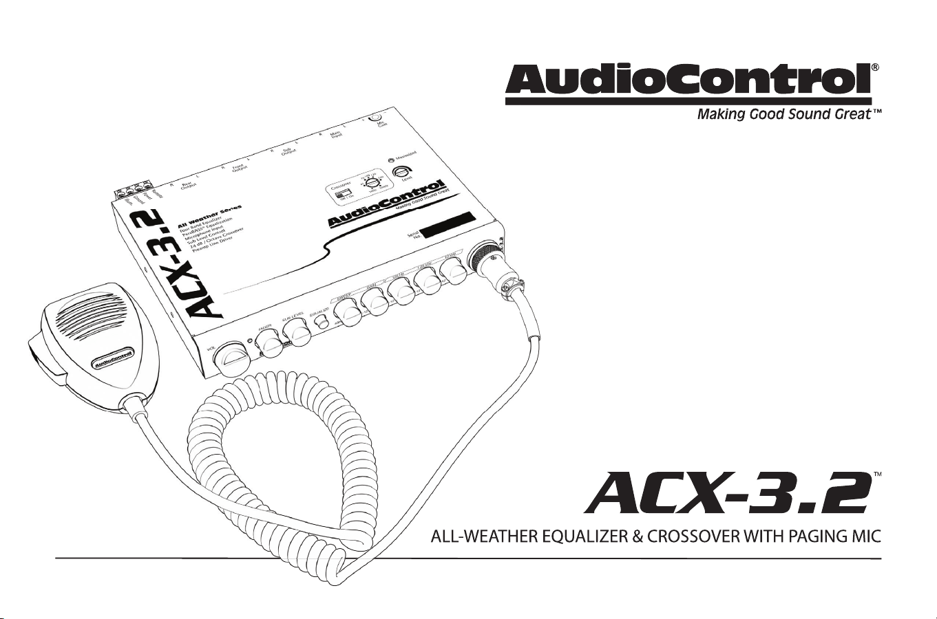
ALL-WEATHER EQUALIZER & CROSSOVER WITH PAGING MIC
ALL-WEATHER EQUALIZER & CROSSOVER WITH PAGING MIC
Owner’s Enjoyment Manual
Features
• 4-Band Stereo Graphic EQ
• ParaBASS® Low Frequency Contouring
• Variable 24 dB/Octave Linkwitz-Riley Crossover
• Front, Rear, and Subwoofer Outputs
• Master Volume, Fader, and Sub Level Control
• High-Gain Input Stage
• Line Driver: 9.5 Volts Peak Output
• Dash or Console-Mountable
• Included Paging Microphone
• The Silent Watchfulness of the Hoh Rainforest
2
Owner’s Enjoyment Manual
1. Read these instructions.
2. Keep these instructions.
3. Heed all warnings.
4. Follow all instructions.
5. Do not submerge this apparatus in water.
6. Clean only with a dry cloth.
7. Do not block any ventilation openings. Install in accordance with the
manufacturer’s instructions.
8. Do not install near any heat sources such as mufflers, silencers, exhaust
pipes, or other apparatus (including amplifiers) that produce heat.
9. WARNING: Improper installation may lead to permanent injury or death.
Installation of the apparatus must be done with great care by qualified
personnel, to prevent damage to fuel lines, power and other electrical
wiring, hydraulic brake lines, and other systems, that might compromise
vehicle safety.
10. Provide +12v and ground wiring of sufficient size to ensure adequate
current to the receiver. For the ACX-3.2, this means 16-22 gauge wire.
11. Use rubber grommets to protect wiring whenever passing wires through
metal openings or bulkheads.
12. Only use attachments/accessories specified by the manufacturer.
13. Refer all servicing to qualified service personnel. Servicing is required
when the apparatus has been damaged in any way, such as the power
input terminals are damaged, objects have fallen into the apparatus,
does not operate normally, or has been dropped.
14. Fuses shall be replaced only with the correct type and fuse value, and
only when the apparatus is powered off.
15. Exposure to high sound pressure levels may lead to permanent hearing
loss. Take every precaution to protect your hearing.
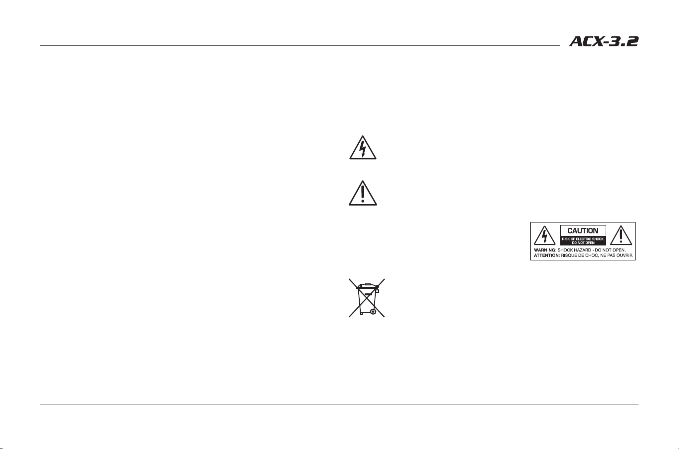
The lightning flash with arrowhead symbol within an equilateral
triangle is intended to alert the user to the presence of uninsulated
“dangerous voltage” within the product’s enclosure, that may be of
sufficient magnitude to constitute a risk of electric shock to persons.
The exclamation point within an equilateral triangle is intended to
alert the user of the presence of important operating and mainte-
nance (servicing) instructions in the literature accompanying the
appliance.
Caution: to reduce the risk of electric shock, do
not disassemble the apparatus, other than to
remove the top panel to access the controls.
There are no user-serviceable parts inside. Refer
servicing to qualified personnel.
Recycling notice: If the time comes and this apparatus has fulfilled
its destiny, do not throw it out into the trash. It has to be carefully
recycled for the good of mankind, by a facility specially equipped
for the safe recycling of electronic apparatii. Please contact your
local or state recycling leaders for assistance in locating a suitable
nearby recycling facility. Or, contact us and we might be able to
repair it for you.
Important Safety Instructions
3
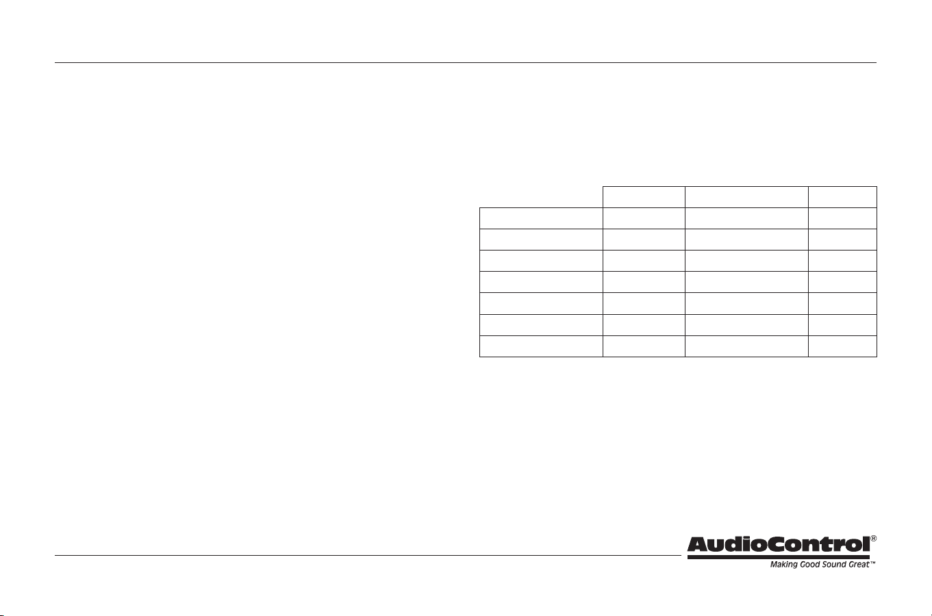
For those of you who are short on time and brimming with confidence, or
caffeine for that matter, refer to pages 9 through 14. As a matter of reference
the ACX-3.2 is shipped in the following configuration:
AudioControl builds high performance, technical products and we invest
considerable time training with our dealers to get the maximum performance
from each product. That is why we recommend that you consider having your
authorized AudioControl dealer install your ACX-3.2.
Quick Start
Shipped Option Page
Main Input Balanced Unbalanced 6
Microphone Routing Rear Outputs Front & Rear Outputs 6
Ground Isolation Isolated 200 Ω or Ground 6
Illumination Color Cool Blue Hot Red 6
Input Gain Unity 0 dB to +20 dB 7
Crossover State Off On 7
Crossover Frequency 100 Hz 30 Hz to 300 Hz 7
Table of Contents
Important Safety Instructions ..................................2
Quick Start .....................................................3
A Guided Tour of the ACX-3.2 ...................................4
Installing the ACX-3.2 ...........................................9
Placement and Mounting ......................................9
Power Wiring ..................................................10
Audio Wiring ..................................................11
Level Matching ................................................13
Adjusting the Equalizer ........................................14
Troubleshooting ...............................................15
The Warranty ...................................................16
Legalese Section ................................................17
Dimensions .....................................................18
Specifications ...................................................19
4
Owner’s Enjoyment Manual
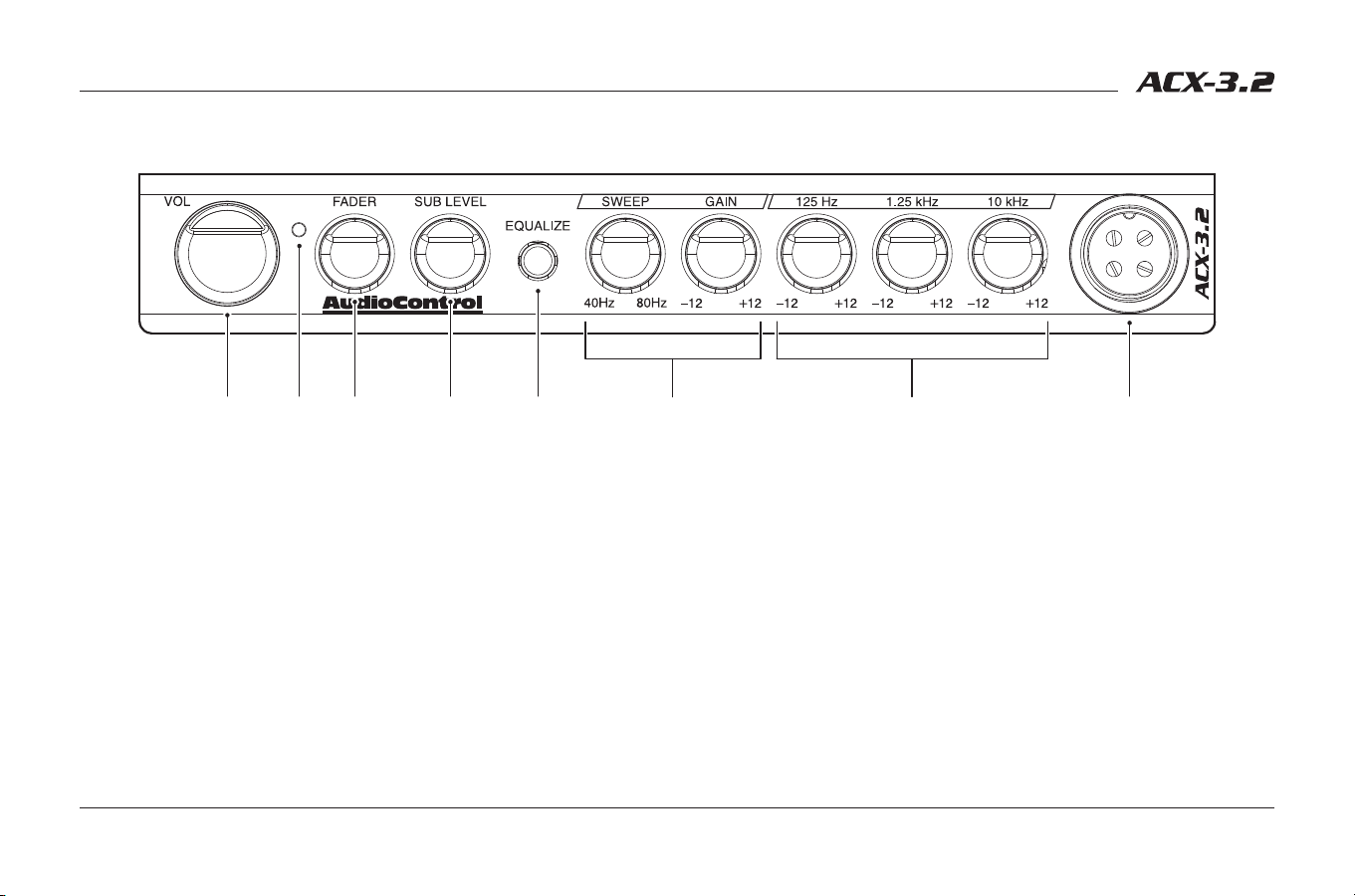
1. Volume Control – Because the ACX-3.2 is a true pre-amp, it serves as the
main control unit in the audio system. It has a master volume control that
controls the output to all of your amplifiers.
2. Power LED – When the ACX-3.2 is powered on, this blue LED will shine
bright and proud.
3. Fader – When amplifier channels are connected to the front and rear
outputs, the fader control will allow you to fade the signal level back and
forth.
4. Sub Level – Exactly what it says it is. Controls the amount of signal that
goes to the subwoofer output of your ACX-3.2.
5. Equalize – Push this button in to active the EQ. When the button is out, EQ
is bypassed.
6. ParaBASS® Controls – Two simple controls allow for killer bass tweaking.
The sweep knob selects the center frequency, between 40 Hz and 80 Hz.
The gain knob provides 10 dB of boost or cut, centered around the sweep
frequency.
7. Graphic Equalization Bands – Three stereo controls centered at 125 Hz,
1.25 kHz, and 10 kHz with 10 dB of boost or cut. These controls should
be used to tweak your system, depending upon your mood or program
material.
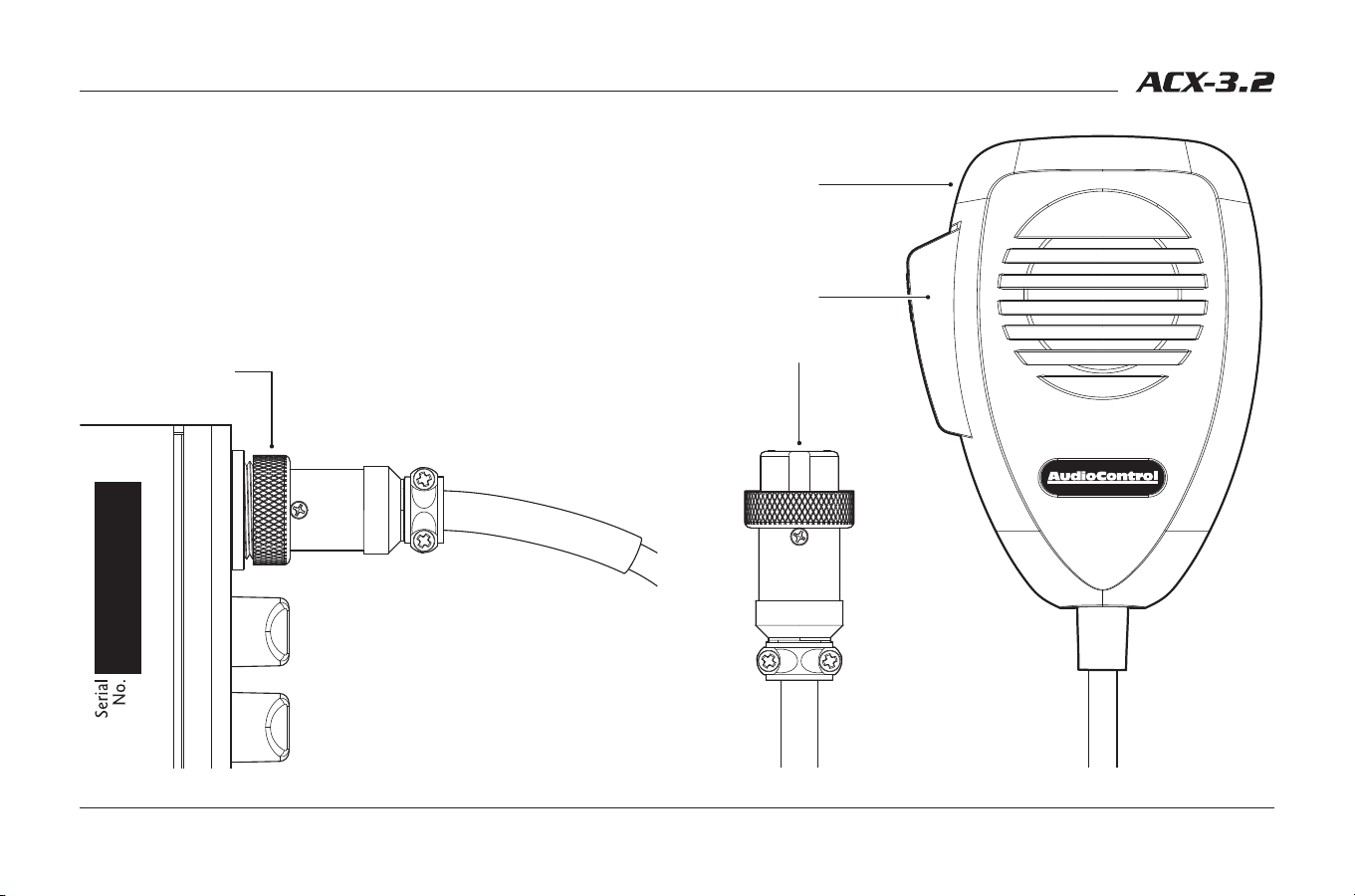
8. Microphone Input Jack – Connect the included paging microphone here.
The microphone cable connector should be secured to this input using its
integrated locking ring.
A Guided Tour of the ACX-3.2
q ew r t iy u
5
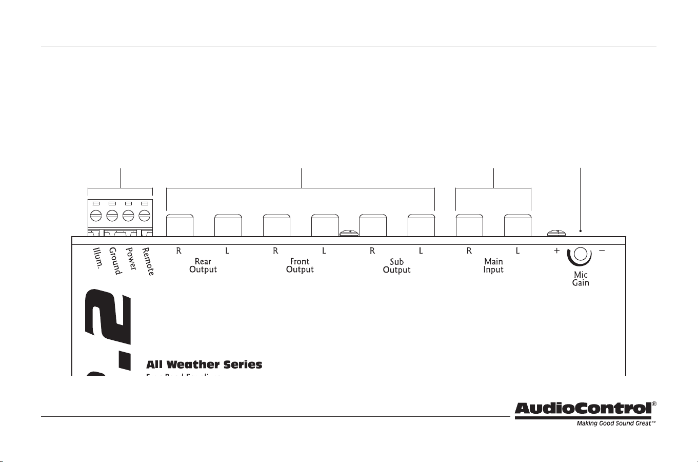
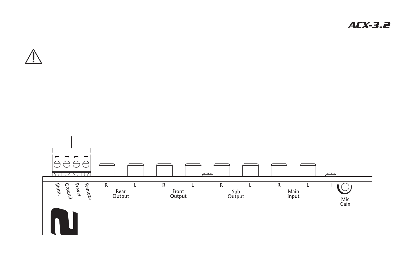
9. Microphone Input Gain – This adjustment pot can be used to achieve a
nice balance between microphone level and source level.
10. Input RCAs – Connect outputs of your source to these inputs.
11. Output RCAs – Next to the inputs are the outputs, which should be
connected to the front, rear and subwoofer amplifiers, if applicable.
12. Power Connections – This nifty connector is a blessing to anyone who
has tried to wire up their gear with their head crammed under the dash.
You can wire up the power, ground, remote turn-on, and illumination from
the convenience of the driver’s seat and then casually plug it in the back of
your ACX-3.2.
1)1@ o1!
Guided Tour of the ACX-3.2 (continued)
6
Owner’s Enjoyment Manual
Ground
Isolated
200Ω
Blue
Red
Unbalanced
Balanced
BALANCED INPUT
MIC SIGNAL ROUTING
GROUND ISOLATION
ILLUMINATION
Front/Rear
Rear
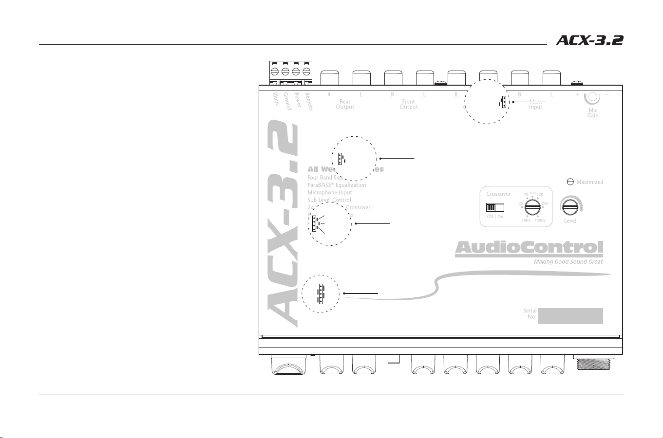
13. Balanced Input – (Located under the cover).
These jumpers allow you utilize or bypass the
balanced input circuitry. Although it is shipped
in the balanced mode, which is often best, it may
be necessary to change this depending upon the
confi guration of the components you use.
14. Mic Signal Routing – (Located under the cover).
From the factory, signal from the microphone is
routed to the rear outputs. This jumper allows you
to route microphone signal to both front and rear
outputs if desired. Watch out for feedback!
15. Ground Isolation – (Located under the cover).
This feature allows you to change the power
supply ground for diff erent systems. When the
ACX-3.2 is shipped from the factory, the jumper
is set to the fully isolated position, which is
generally the best. If you have a ground loop noise
(alternator whine) in your system, experiment
with diff erent settings. To change the settings, turn
the system off , carefully move the black jumper
from the center two pins (Isolated), and move it to
either the top two pins (200 Ω), or the bottom two
pins (Ground).
16. Illumination – (Located under the cover). These
jumpers let you change the back-light illumination
to Cool Blue or Hot Red. Given that we are
acclimated to sun-free life in the rainforest, we
have shipped the ACX-3.2 in the Cool Blue mode.
1#
1
1
1
Guided Tour of the ACX-3.2 (continued)
7
1& 1* 1(
2)
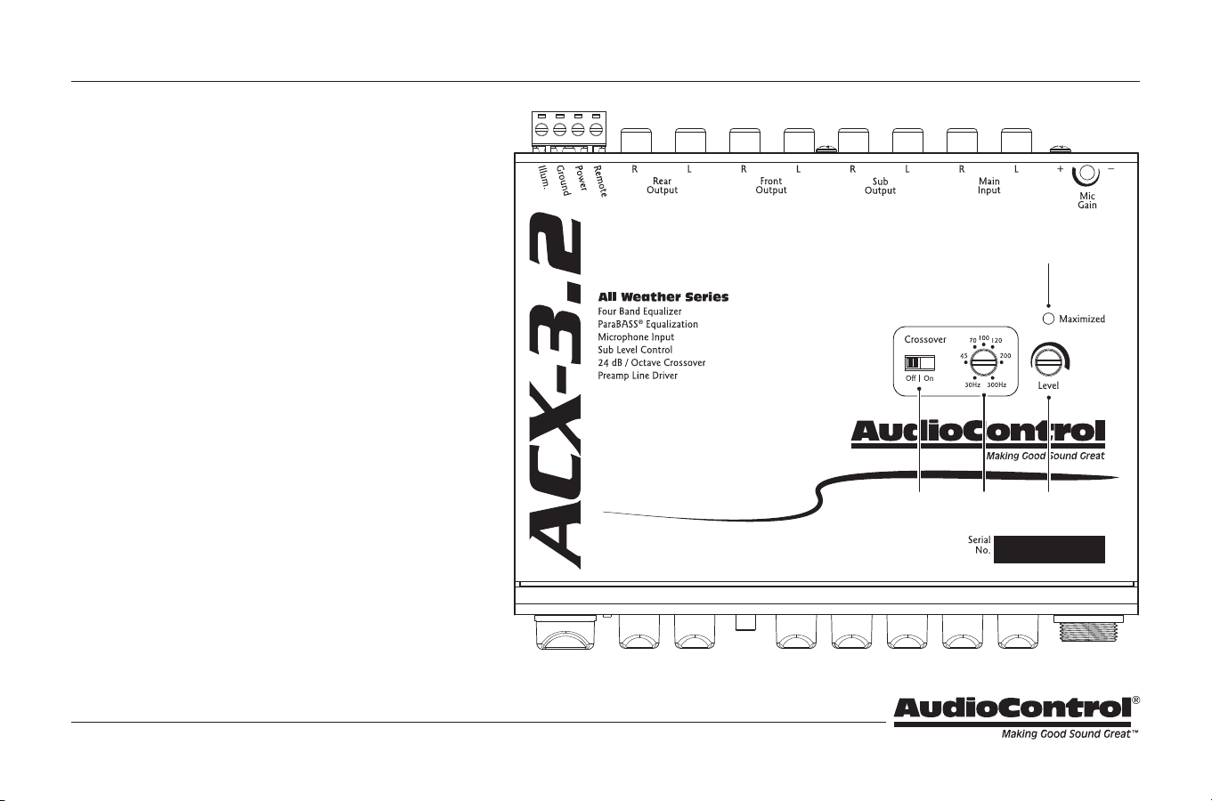
17. Crossover Bypass – By default, the crossover state is set
to off. When in the off state, full range signal is passed
from the main input to the front and rear outputs. When
in the on state, the front and rear outputs will receive a
high passed signal at the set crossover frequency. The
sub output will receive a low passed signal at the set
crossover frequency whether the crossover is on or off.
18. Crossover Frequency – The frequency setting of this pot
determines the frequency that the front and rear outputs
of your ACX-3.2 will play down to, as well as determining
where your subwoofer will begin playing. The Crossover
Bypass Switch (
1&
) lets you defeat the crossover, so if
your system does not use a separate subwoofer, all your
amplifiers will get a full range signal.
19. Input Level – This pot is used to increase the amount of
signal voltage to your power amplifiers. With this control
you can provide up to 9.5 Volts (peak) to your amplifier’s
inputs. Check with your amplifier manufacturer’s specs
to determine exactly how much voltage they can
really handle. More info on this in the section on “Level
Matching” page 12.
20. Gain Maximized LED – This LED indicates when gain
has been maximized for optimum performance. With
your source unit turned up to 75% (or maximum output
below distortion), use the Input Level controls to dial in
the input gain, watching for this LED to shine, then back
it off just a touch.
Guided Tour of the ACX-3.2 (continued)
8
Owner’s Enjoyment Manual
21. Paging Microphone – The ACX-3.2 comes with a nice, hand-held paging
microphone, suited for a number of applications where amplified
reinforcement of your vocalizations is desired.
22. Push to Talk Button – To speak into the microphone, press and hold the
Push to Talk (PTT) button on the side. Release the button when you are
done speaking. For the best sound quality, hold the microphone 2 inches
away from your mouth and speak in a normal voice.
23. Microphone Connector – Align the microphone connector with the jack
on the front of the ACX-3.2. Push the connector in firmly and secure it with
the locking ring.
Guided Tour of the ACX-3.2 (continued)
2@
2!
2#
9
Installing the ACX-3.2
If you don’t feel comfortable with everything you have read up to this point,
run, don’t walk to your nearest authorized AudioControl dealer and let them
install it. Life is too short to be tearing your hair out over your audio system.
Placement and Mounting
Placement – The ACX-3.2 was designed to be installed on or near the
dashboard or console in most vehicles. However, depending on the
needs of the system, the ACX-3.2 is an ideal pre-amp control that can be
mounted in the front and/or the rear of the vehicle.
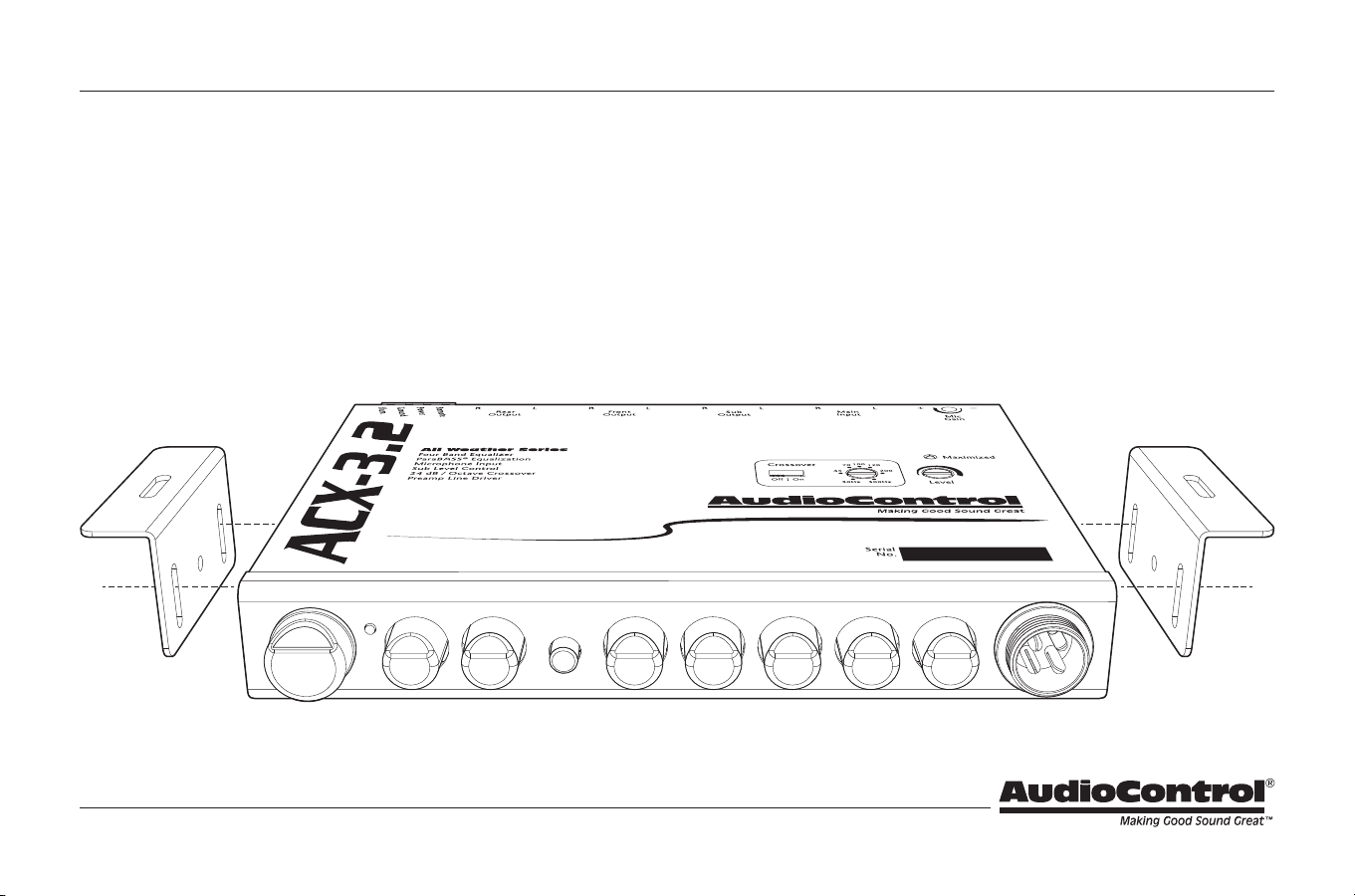
Mounting – The ACX-3.2 and microphone are designed to be physically
mounted almost anywhere in a vehicle, although it is recommended to
avoid hot spots like the firewall, engine compartment, or tail pipe. While
the ACX-3.2 is protected from corrosion with a conformal coating on the
printed circuit board, the mounting location should be safe from water
seepage or areas with bad seals. We have provided brackets to assist you
in mounting the ACX-3.2 chassis and microphone in a suitable location.
Dimensions – See page 18 for further detail on mounting and dimensions.
10
Owner’s Enjoyment Manual
Power Wiring
Disconnect the negative terminal of your car’s battery before
working on any electrical connections. Failure to do so could lead to
a dramatic spark in your life.
Remote Turn-On – Connect a 22 to 18 gauge wire from a head-unit’s remote
turn-on or from a switched 12 volt source to the “Remote” connector on
the ACX-3.2.
Positive (+12 V) Connection – Insert an 18 to 16 gauge wire into the
connector labeled “Power” on the nifty connector of your ACX-3.2.
Connect it to a good, constant fused source of 12 volts (we suggest the
battery).
Ground Connection – Use the same gauge wire as you did for the positive
connector and run it from the “Ground” connector on the ACX-3.2 to
the negative terminal of the battery, a ground buss, or a verified ground
location. The factory head unit ground is not recommended.
Illumination – The connector labeled “Illumination” on your ACX-3.2 provides
power to the back-lighting of your unit. Connecting it to a switched 12
volt source, such as the “Remote” will light up the back-lighting of your
ACX-3.2. A really cool idea is to connect the illumination wire to a factory
dash light dimmer and have the ability to dim the back-lighting of the
ACX-3.2 with your dash lights.
Power Connector
Installing the ACX-3.2 (continued)
11
Audio Wiring
As you may already have guessed, there are numerous ways to configure the
ACX-3.2 in your audio system. The following diagrams are just a few of the
possibilities.
Installing the ACX-3.2 (continued)
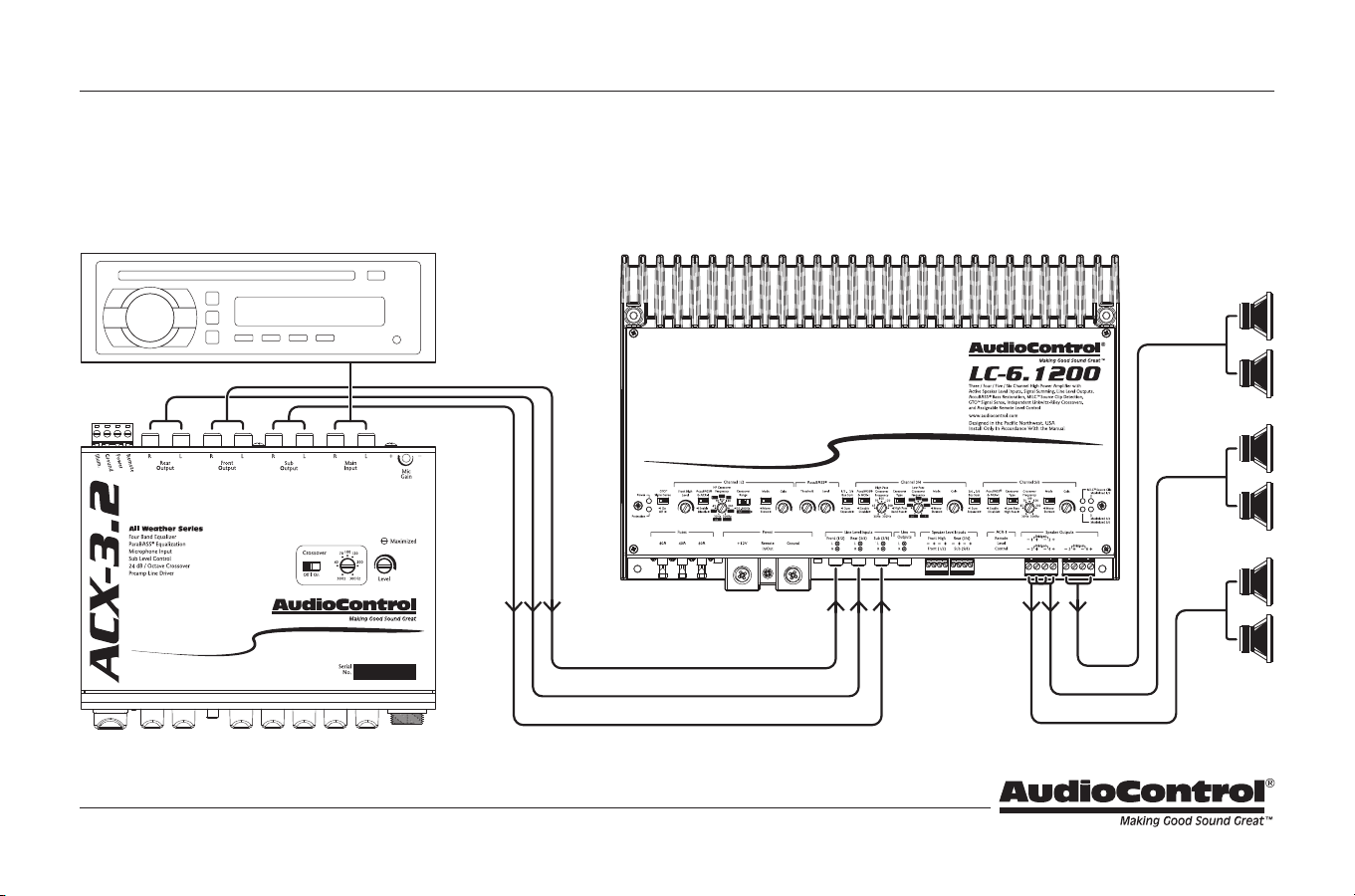
System #1: Basic Six-Channel System
Front Output
Sub
Rear
Front
Rear Output
Sub Output
Head Unit/
Media Center
12
Owner’s Enjoyment Manual
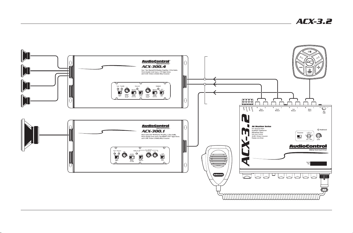
System #2: All-Weather Wake Sports Boat System with Paging
Installing the ACX-3.2 (continued)
Rear L/R Out
to Tower
Speakers
Sub
Tower (R)
Tower (L)
Cockpit (R)
Cockpit (L)
ACX-BT3
All-Weather
Bluetooth
®
Receiver
Paging Mic
Mic Signal Routing jumper: Rear (Tower)
Front L/R Out
to Cockpit/Bow
Speakers
13
Level Matching
Many source units produce signal voltages in the area of 2 to 4 volts. However,
you typically only achieve these voltage levels when the volume is turned all
the way up. By following the level matching steps for the ACX-3.2 you will be
able to take full advantage of the high voltage output of your source.
1. Disconnect the RCA cables leading into your amplifiers, and make sure the
only RCA cables between your source unit and the ACX-3.2’s main inputs
are attached. Turn the volume level knob on the ACX-3.2 to maximum.
2. Play a favorite audio track contains consistent, dynamic music and turn the
source unit’s volume control up to its maximum level. (NOTE: Some source
units may produce distortion or “clipping” when their volume controls
are turned all of the way up. If this happens, you will hear distortion even
at low levels when you connect the rest of the system. If this is the case,
lower the source unit’s volume level until you no longer hear distortion).
The volume control on the ACX-3.2 will now be the master volume control.
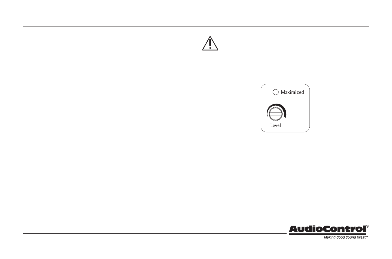
3. Using the included AudioControl guitar pick, or a small screwdriver,
adjust the Input Level control on the top of the ACX-3.2 until the yellow
Maximized LED starts to flicker with the music. (NOTE: If the Maximized
light does not come on because of the low output of the source unit, turn
the Input Level pot to maximum).
Important Tip: If the Maximized light does not come on, because of the
low output of the source unit, turn the Input Level to maximum. Please
refer to the amplifier manufacturer’s specifications on input voltage
to determine whether you will need to decrease the Input Level on the ACX-3.2
to avoid clipping the next component in line. If the next component in line is an
AudioControl component, there is no need to re-adjust the Input Levels, because
they can handle the hot signal voltage the ACX-3.2 produces.
4. Turn off the entire system and attach the output RCAs from the ACX-3.2 to
the next component in line.
5. Turn down the gain control on your amplifiers to the least sensitive setting
which is turning the gain control counter clockwise. This will allow you to
drive a hotter signal in to your amplifiers.
Installing the ACX-3.2 (continued)
14
Owner’s Enjoyment Manual
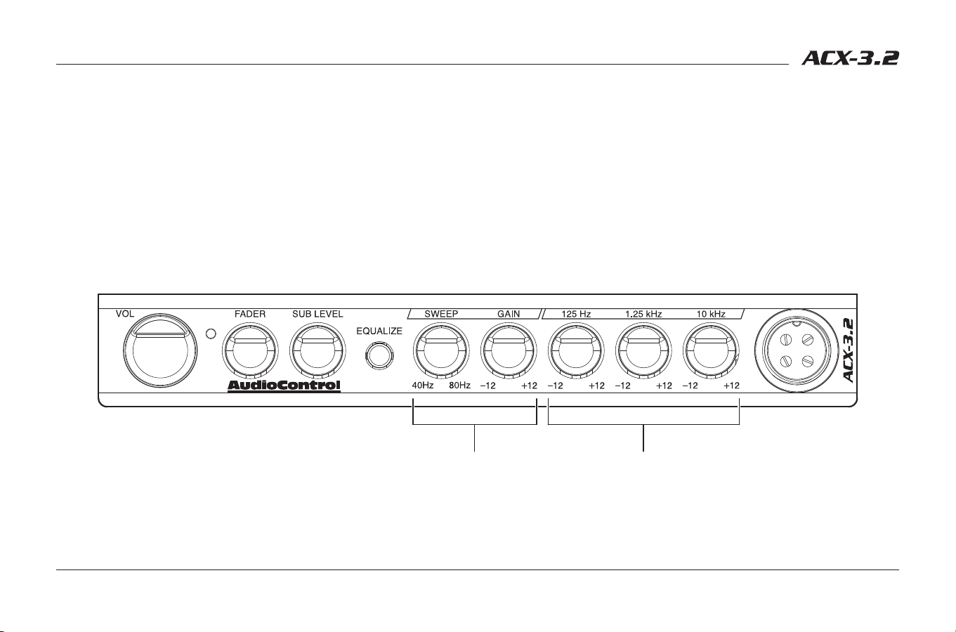
Adjusting the Equalizer
Stereo Bands – There are no specific guidelines as to setting the main
equalizer controls on the ACX-3.2. Keep in mind that music can sound
different depending upon who is listening and what type of music they
are listening to. For some mid-bass kick, give the 125 Hz knob a whirl. On
the other hand if your front and rear speakers are having trouble keeping
up with your subwoofer then crank 125 Hz down a notch. If the vocals
need some boosting or even toning down, us the 1.25 kHz controls. The
frosting on any recording is always the higher frequencies. The 10 kHz
control lets you provide just enough frosting or you can cut back so you
don’t get any cavities.
Stereo EQ BandsParaBASS
®
Controls
ParaBASS® Controls – The ParaBASS system control works with any system
that can reproduce bass in the 40 Hz to 80 Hz range. The bass response in
a system is affected by four factors: (1) the acoustics of the vehicle, (2) the
location of the speakers, (3) the music source you are listening to, and (4)
the speakers used. Because of the variations in the recording process, we
developed The Epicenter® to help restore any low frequencies lost during
the recording process. However, the acoustics of various environments
are different. With this in mind our coffee-laden engineers developed
the unique ParaBASS system. The Sweep control allows you to select a
center frequency (the frequency most affected) between 40 Hz and 80 Hz.
The Gain control then allows you to boost or cut (±10 dB) at the selected
frequency.
Installing the ACX-3.2 (continued)
15
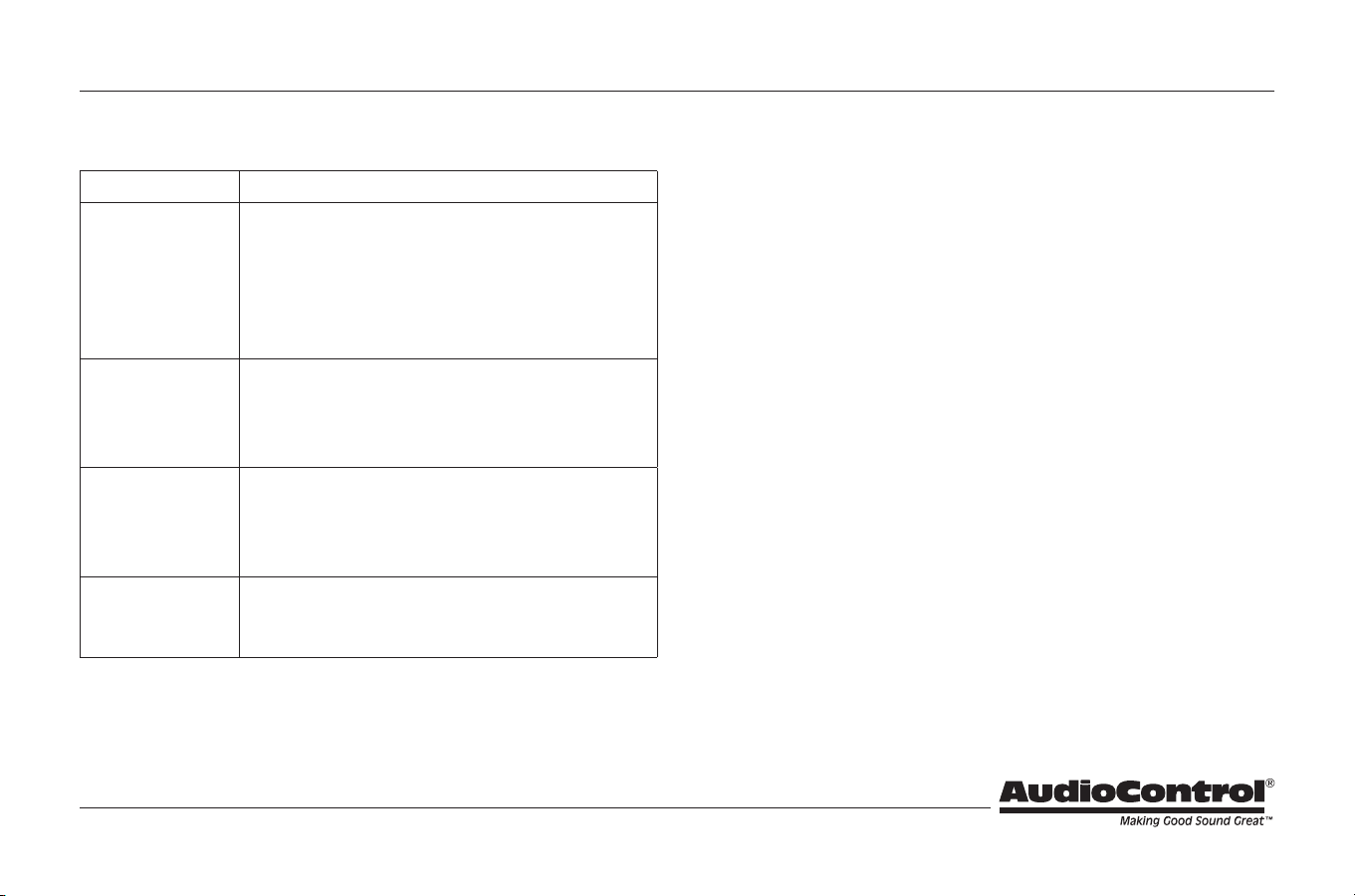
Troubleshooting
Problem Suggestions
No Sound 1. Is a source connected to the inputs?
2. Check power and remote turn on for proper volt-
age. Is the power LED on?
3. Center the fader control.
4. Turn up the Input Level control.
5. Check ground connections.
Hiss 1. Turn down the amp gains.
2. Turn down the amp gains.
3. Turn down the amp gains.
4. Adjust the source unit output.
Distorted Audio 1. Adjust EQ levels.
2. Adjust gain levels.
3. Lower the volume level of the source unit.
4. Lower subwoofer level.
Alternator Whine 1. Confirm that all components are using the same
ground point.
2. Change ground isolation jumper (see page 6, #15).
Installing the ACX-3.2 (continued)

16
Owner’s Enjoyment Manual
In just the same way as being covered in honey and thrown into a dark pit
full of hungry woodchucks, people are scared of warranties. Lots of fine print.
Months of waiting around. Well, fear no more. This warranty is designed to
make you rave about AudioControl. It’s a warranty that looks out for you and
your client, plus helps you resist the temptation to have your friend Sparky,
who’s “good with electronics,” try to repair your AudioControl product. So go
ahead, read this warranty, then register the information at www.audiocontrol.
com/product-registration and include your comments.
Our warranty has conditional conditions! “Conditional” doesn’t mean anything
ominous. The Federal Trade Commission tells all manufacturers to use the term
to indicate that certain conditions have to be met before they’ll honor the war-
ranty. If you meet all of these conditions, AudioControl will, at its discretion,
repair or replace any AudioControl products that exhibit defects in materials
and/or workmanship during the warranty on your product for five (5) years
from the date you bought it, and we will fix or replace it, at our option, during
that time.
Here are the conditional conditions:
1. You must fully register your purchase within 15 days of the purchase date
by going to the AudioControl product registration page at www.audiocon-
trol.com/product-registration. Failure to register your product will negate
the warranty.
2. You need to hold on to your sales receipt! All warranty service requires
original sales receipt documentation. The warranty only applies to
the original purchaser from an authorized AudioControl dealer. Note:
Products purchased from unauthorized dealers are not covered under
warranty.
3. If an authorized AudioControl dealer installs your AudioControl product,
the warranty is five years.
4. Our warranty covers AudioControl products that have been installed
according to the instructions in the installation manual.
5. You cannot let anybody who isn’t: (A) the AudioControl factory; or (B)
somebody authorized in writing by AudioControl service your AudioCon-
trol product. If anyone other than (A), or (B) messes with your AudioCon-
trol product, the warranty is void.
6. The warranty is void if the serial number is altered, defaced or removed,
or if your product has been used improperly. Now that may sound like a
big loophole, but here is what we mean by this: Unwarranted abuse is: (A)
physical damage (don’t use your product to level your dining room table);
(B) improper connections (120 volts into the RCA jacks can fry the poor
thing). This is the best product we know how to build, but for example if
you mount it to the front bumper of your car, drop it over the Niagara Falls
or use it for Clay Pigeon shooting practice, something will go wrong.
Assuming you conform to 1 through 6, and it really isn’t all that hard to do,
we get the option of fixing your product or replacing it with a new one at our
discretion.
In the event that your product is out of warranty or not covered under our
warranty you may request to have any damage repaired at our normal “Out of
Warranty” repair cost.
The Warranty
Please Remain Calm

17
Legalese Section
This is the only warranty issued by AudioControl. This warranty gives you
specific legal rights, and you may also have rights that vary from state to state.
Promises of how well your AudioControl product will work are not implied by
this warranty. Other than what we’ve said we’ll do in this warranty, we have
no obligation, express or implied. We make no warranty of merchantability or
fitness for any particular purpose. Also neither we nor anyone else who has
been involved in the development or manufacture of the unit will have any
liability of any incidental, consequential, special or punitive damages, includ-
ing but not limited to any lost profits or damage to other parts of your system
by hooking up to the unit (whether the claim is one for breach of warranty,
negligence of other tort, or any other kind of claim). Some states do not allow
limitations of consequential damages.
Please Remain Calm (continued)
18
Owner’s Enjoyment Manual
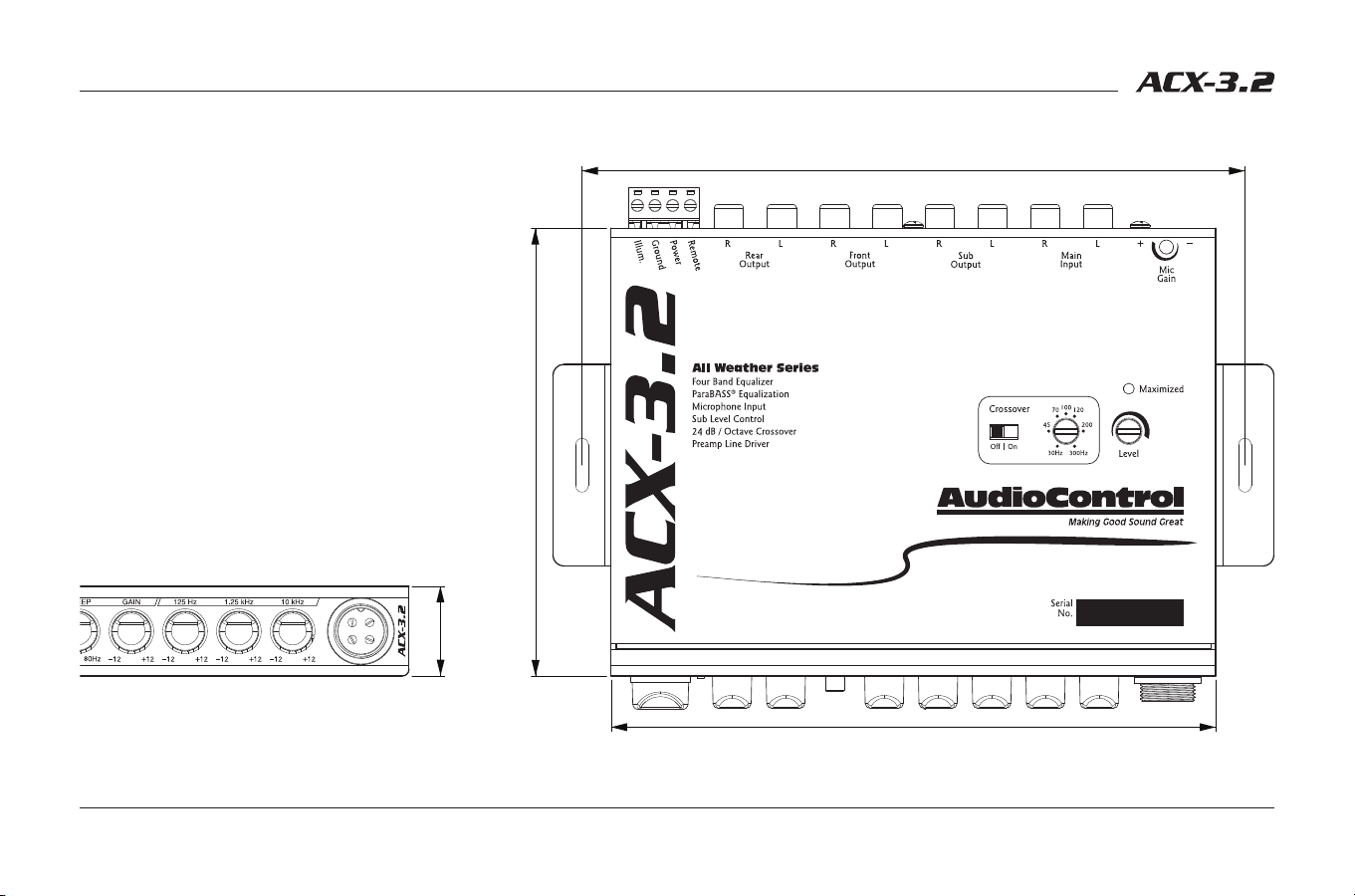
Dimensions
7.4 in [188.0 mm]
6.8in [171.5 mm]
5.0 in [127.0 mm]
1.0 in [25.4 mm]
The compact, half-DIN size makes the ACX-3.2 easy
to install and integrate into most vehicles. We have
provided brackets to assist you in mounting the
ACX-3.2 chassis under a dashboard, glove box or
any vehicle console. The screw holes on the ACX-3.2
chassis also allow for easy installation underneath
a radio or with a dash kit. Be sure to account for
additional space behind the ACX-3.2 for power and
signal connections.

19
Specifications
ACX-3.2 All-Weather EQ & Crossover
Maximum Input/Output Level . . . . . . . . . . . . . . . . . . . . 7 Vrms / 9.5 V peak
Frequency Response . . . . . . . . . . . . . . . . . . . . . . . . . . .20Hz-20kHz; ±0.1 dB
Total Harmonic Distortion . . . . . . . . . . . . . . . . . . . . . . . . . . . . . . . . . . . . . 0.03%
Signal to Noise Ratio (Inputs Set to Balanced) ................ -123 dB
Input Impedance .............................................20 kΩ
Output Impedance. . . . . . . . . . . . . . . . . . . . . . . . . . . . . . . . . . . . . . . . . . . . 150 Ω
Input Gain .............................................0 dB to 20 dB
Equalization Boost/Cut ......................................±10 dB
Crossover Slope ..........................24 dB/octave Linkwitz-Riley
Microphone Frequency Response ....................100 Hz to 6 kHz
Microphone Maximum SPL. . . . . . . . . . . . . . . . . . . . . . . . . . . . . . . 130 dB SPL
Power Supply . . . . . . . . . . . . . . . . . . . . . . . High Headroom PWM Switching
Power Draw ................................................. 300 mA
Recommended Fuse Rating ......................................1 A
Illumination Color. . . . . . . . . . . . . . . . . . . . Blue or Red (LED back-lighting)
Size ............................................. 6.75”W x 5”D x 1”H
Weight ......................................................1.6 lbs.
All specifications are measured at 14.4 VDC (standard automotive voltage). As technology advances, AudioControl reserves the right to continuously change our specifica-
tions, like our Pacific Northwest weather, although we are working on changing that as well.
For more information about this fine product, and for details of the limited
warranty and repair services, please visit www.audiocontrol.com
AudioControl, Inc.
22410 70th Avenue West
Mountlake Terrace, WA 98043 USA
Phone: 425-775-8461
email: sound.great@audiocontrol.com
©2022 AudioControl. All rights reserved.
All specifications are subject to being covered in hot sauce without notice.
Owner’s Enjoyment Manual PN 913-174-0 Rev B
The End
