HUSSONG MANUFACTURING CO., INC.
INSTALLATION AND
OPERATION MANUAL
ͷ Do not store or use gasoline or other
ammable vapors and liquids in the vicinity
of this or any other appliance.
ͷ WHAT TO DO IF YOU SMELL GAS
• Do not try to light any appliance.
• Do not touch any electrical switch; do
not use any phone in your building.
• Leave the building immediately.
• Immediately call your gas supplier from
a neighbor’s phone. Follow the gas
supplier’s instructions.
• If you cannot reach your gas supplier,
call the re department.
ͷ Installation and service must be performed
by a qualied installer, service agency or
the gas supplier.
WARNING:
FIRE OR EXPLOSION HAZARD
Failure to follow safety warnings exactly
could result in serious injury, death, or
property damage.
This appliance may be installed in
an aftermarket, permanently located,
manufactured home (USA only) or mobile
home, where not prohibited by local codes.
This appliance is only for use with the type
of gas indicated on the rating plate. This
appliance is not convertible for use with other
gases, unless a certied kit is used.
INSTALLER: Leave this manual with the appliance.
CONSUMER: Retain this manual for future reference.
English and French installation manuals are available through your
local dealer. Visit our website www.kozyheat.com.
Les manuels d’installation en français et en anglais sont disponibles
chez votre détaillant local. Visitez
www.kozyheat.com
.
DANGER
HOT GLASS WILL
CAUSE BURNS
DO NOT TOUCH GLASS
UNTIL COOLED
NEVER ALLOW CHILDREN
TO TOUCH GLASS
A barrier designed to reduce the risk of burns
from the hot viewing glass is provided with this
appliance and shall be installed for the protection
of children and other at-risk individuals.
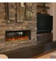
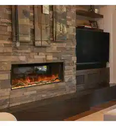
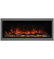
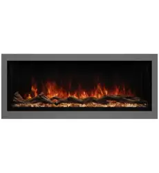
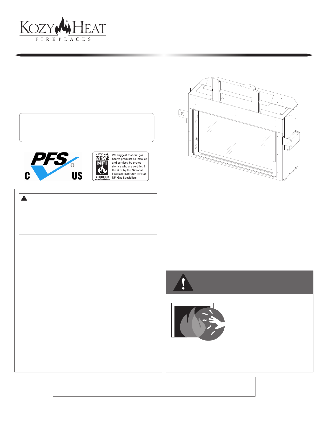
BELLINGHAM 44
Model #BHM-44
Direct Vent Gas Fireplace
Hussong Mfg. Co., Inc.
BHM-44 Report No: 20-605
Rev.1, August 2020
Starting Serial Number: 20 200000 36

#BHM-44 R.1 August 2020 Hussong Mfg. Co., Inc. • Kozy Heat Fireplaces
3
Read this manual before installation or operating this appliance.
Please retain this owner’s manual for future reference.
CON GRAT ULAT ION S!
We welcome you as a new owner of a Kozy Heat gas fireplace. Kozy Heat products are
designed with superi components and materials, and assembled by trained crasmen who
take pride in their wk. To ensure you receive a quality product, the burner and valve assembly
are 100 percent test-fired, and the complete fireplace is thoughly inspected befe packaging.
Our commitment to quality and customer satisfaction has remained the same f over 40 years.
We oer a complete line of gas and wood fireplaces, along with stylish accessies to complement
any dec. Adding a fireplace is one of the best ways to increase the value of your home, and
we are proud to oer a netwk of dealers throughout the country to help make your experience
everything you imagine. We pride ourselves in being dedicated not only to functionality and
reliability, but also customer safety. We oer our continual suppt and guidance to help you
achieve the maximum benet and enjoyment om your Kozy Heat gas fireplace.
Jim Hussong
President
Dudley Hussong
Board Chairman
Homeowner Reference Information
We recommend you record the following information:
Model Name: ____________________________________________
Serial Number: ___________________________________________
Dealership Purchased from: ________________________________
Date purchased/installed: __________________________________
Location of replace: ______________________________________
Dealer phone: ___________________________________________
Notes: ______________________________________________________________________________________________________________
____________________________________________________________________________________________________________________
____________________________________________________________________________________________________________________
____________________________________________________________________________________________________________________


#BHM-44 R.1 August 2020 Hussong Mfg. Co., Inc. • Kozy Heat Fireplaces TABLE OF CONTENTS 5
TABLE OF CONTENTS
TABLE OF CONTENTS .....................................................................5
1.0 INTRODUCTION ......................................................................7
1.1 Appliance Certication ............................................................................. 7
1.2 California Proposition 65 Warning ........................................................ 7
1.3 Requirements for the Commonwealth of Massachusetts ............ 7
2.0 SPECIFICATIONS .....................................................................8
2.1 Heating Specications .............................................................................. 8
2.2 Electrical Specications ............................................................................ 8
2.3 Appliance Dimensions .............................................................................. 9
2.4 Safety Barrier Screen Dimensions ......................................................... 10
3.0 FRAMING .................................................................................11
3.1 Installation Planning .................................................................................. 11
3.2 Nailing Flange Assembly and Installation .......................................... 12
3.3 Stand-o Assembly and Header Heat Shield .................................... 13
3.4 Clearances to Combustibles ................................................................... 14
3.5 Rough Framing ............................................................................................ 15
3.6 Natural Draft Vent Termination Rough Framing .............................. 16
3.7 Outdoor Covered Fireplace Installation .............................................. 18
3.8 Exterior and Interior Heat Transfer Kit Cover Plates........................20
3.9 Vented Cavity and Komfort Zone Kit Installation ............................ 21
4.0 FACING AND FINISHING .........................................................29
4.1 Standard Installation Facing and Finishing Requirements ......... 29
4.2 Safety Barrier Installation ......................................................................... 35
4.3 Vented Cavity and KZK Facing and Finishing Requirements ..... 36
5.0 GAS LINE CONNECTION .........................................................40
5.1 Gas Conversion ............................................................................................ 40
5.2 Gas Line Installation ................................................................................... 40
6.0 NATURAL DRAFT TERMINATION LOCATIONS ......................41
6.1 Vertical Natural Draft Vent Termination .............................................. 41
6.2 Minimum Natural Draft Vent Termination Clearances ................... 42
7.0 VENTING ..................................................................................43
7.1 Approved Vent Systems ............................................................................ 43
7.2 Venting Requirements .............................................................................. 43
7.3 Natural Draft Vent Restriction ............................................................... 44
7.4 Natural Draft Installation .......................................................................... 45
7.5 Class A Chimney/Masonry Chimney Conversion ............................ 48
8.0 FIREPLACE SETUP ................................................................... 49
8.1 Glass Frame Assembly ............................................................................... 49
8.2 Gas Valve Access Cover Plate Removal and Installation ............... 49
8.3 Safety Barrier Installation ......................................................................... 50
8.4 Panel Installation .........................................................................................51
8.5 #BH44-500 Log Set Installation .............................................................. 52
8.6 Control Board Access, Removal and Installation ............................. 54
9.0 ELECTRICAL INFORMATION ..................................................56
9.1 Electrical Specications ............................................................................ 56
9.2 Wiring Requirements ................................................................................. 56
9.3 Outlet Junction Box ................................................................................... 57
9.4 Ember Bed Light Kit (auxiliary) ............................................................... 57
9.5 Top Light Kit #600-TLK ............................................................................... 58
10.0 OPERATING INSTRUCTIONS ................................................ 59
10.1 Setup Proame 2 IFC Module .............................................................. 60
10.2 Initialize the Control System................................................................. 60
10.3 Reset the System for Manual Operation .......................................... 60
10.4 Automatic Safety Restart ....................................................................... 60
10.5 Backup Battery Operation .................................................................... 60
10.6 Control System 7 Day Timeout ............................................................ 61
10.7 IFC Module Ignition Sequence ............................................................ 61
10.8 Additional Diagnostic Information .................................................... 61
10.9 Remote Control Operation .................................................................. 62
11.0 ADJUSTMENT ........................................................................66
11.1 Pressure Testing ........................................................................................ 66
11.2 Burner Flame Adjustments ................................................................... 67
12.0 TROUBLESHOOTING.............................................................69
13.0 MAINTENANCE......................................................................71
13.1 Firebox .......................................................................................................... 71
13.2 Fan ................................................................................................................. 71
13.3 Vent System ................................................................................................ 71
13.4 Glass Assembly .......................................................................................... 71
13.5 Burner and Pilot System ........................................................................ 72
14.0 REPLACEMENT PARTS LIST..................................................73
LIMITED LIFETIME WARRANTY ....................................................75


#BHM-44 R.1 August 2020 Hussong Mfg. Co., Inc. • Kozy Heat Fireplaces INTRODUCTION 7
1.0 INTRODUCTION
1.1 Appliance Certication
Laboratory: PFS in Cottage Grove, Wisconsin
Standards:
ANSI Z21.88-2017/CSA 2.33-2017, Vented Gas Fireplace Heaters
CSA 2.17 2017, Gas-Fired Appliances for Use at High Altitudes
This installation must conform with local codes, or in the absence of
local codes, with the National Fuel Gas Code, ANSI Z223.1/NFPA 54, or
the Natural Gas and Propane Installation Code, CSA B149.1.
1.2 California Proposition 65 Warning
WARNING: This product can expose you to chemicals including
Carbon Monoxide, that is an externally vented by-product of fuel
combustion, which is [are] known to the State of California to
cause cancer, birth defects or other reproductive harm. For more
information, visit www.P65Warnings.ca.gov.
1.3 Requirements for the
Commonwealth of Massachusetts
The following requirements reference various Massachusetts and
national codes not contained in this manual.
For all sidewall horizontally vented gas fueled equipment installed
in every dwelling, building or structure used in whole or in part for
residential purposes, including those owned or operated by the
Commonwealth and where the side wall exhaust vent termination
is less than (7) feet above nished grade in the area of the venting,
including but not limited to decks and porches, the following
requirements shall be satised:
1.3.1 Installation of Carbon Monoxide Detectors
At time of installation of side wall horizontally vented gas fueled
equipment, the installing plumber or gas-tter shall observe that
a hard wired carbon monoxide detector with an alarm and battery
back-up is installed on the oor level where the gas equipment is
to be installed. In addition, the installing plumber or gas-tter shall
observe that a battery operated or hard wired carbon monoxide
detector is installed on each additional level of the dwelling, building
or structure served by the side wall horizontal vented gas fueled
equipment. It shall be the responsibility of the property owner
to secure the services of qualied licensed professionals for the
installation of hard wired carbon monoxide detectors.
In the event that the side wall horizontally vented gas fueled
equipment is installed in a crawl space or attic, the hard wired carbon
monoxide detector with alarm and battery back-up may be installed
on the next adjacent oor level. In the event that the requirements
of this subdivision can not be met at the time of completion of
installation, the owner shall have a period of thirty (30) days to
comply with the above requirements; provided, however, that during
said thirty (30) day period, a battery operated carbon monoxide
detector with an alarm shall be installed.
1.3.2 Approved Carbon Monoxide Detectors
Each carbon monoxide detector as required in accordance with the
above provisions shall comply with NFPA 720 and be ANSI/UL 2034
listed and IAS certied.
1.3.3 Signage
A metal or plastic identication plate shall be permanently mounted
to the exterior of the building at a minimum of eight (8) feet
above grade directly in line with the exhaust vent terminal for the
horizontally vented gas fueled heating appliance or equipment. The
sign shall read, in print no less the one-half inch (½) in size, “GAS VENT
DIRECTLY BELOW. KEEP CLEAR OF ALL OBSTRUCTIONS”.
1.3.4 Inspection
The state or local gas inspector of the side wall horizontally vented
gas fueled equipment shall not approve the installation unless, upon
inspection, the inspector observes carbon monoxide detectors and
signage installed in accordance with the provisions of 248 CMR 5.08
(2) (a) 1 through 4.
1.3.5 Exemptions
The following equipment is exempt from 248 CMR 5.08 (2) (a) 1
through 4: The equipment listed in Chapter 10 entitled “Equipment
Not Required To Be Vented” in the most current edition of NFPA 54 as
adopted by the Board; and Product Approved side wall horizontally
vented gas fueled equipment installed in a room or structure separate
from the dwelling, building or structure used in whole or in part for
residential purposes.
1.3.6 Manufacturer Requirements
1.3.6.1 Gas Equipment Venting System Provided
When the manufacturer of Product Approved side wall horizontally
vented gas equipment provides a venting system design or venting
system components with the equipment, the instructions provided
by the manufacturer for installation of the equipment and the
venting system shall include:
• Detailed instructions for the installation of the venting system
design or the venting system components; and
• A complete parts list for the venting system design or venting
system.
1.3.7 Gas Equipment Venting
System NOT Provided
When the manufacturer of Product Approved side wall horizontally
vented gas equipment does not provide the parts for venting the
ue gases, but identies “special venting systems”, the following
requirements shall be satised by the manufacturer:
• The referenced “special venting systems” instructions shall
be included with the appliance or equipment installation
instructions and;
• The “special venting systems” shall be Product Approved by the
Board, and the instructions for that system shall include a parts
list and detailed installation instructions.
A copy of all installation instructions for all Product Approved
side wall horizontally vented gas fueled equipment, all venting
instructions, all parts lists for venting instructions, and/or all venting
design instructions shall remain with the appliance or equipment at
the completion of the installation.
8 SPECIFICATIONS Hussong Mfg. Co., Inc. • Kozy Heat Fireplaces #BHM-44 R.1 August 2020
2.0 SPECIFICATIONS
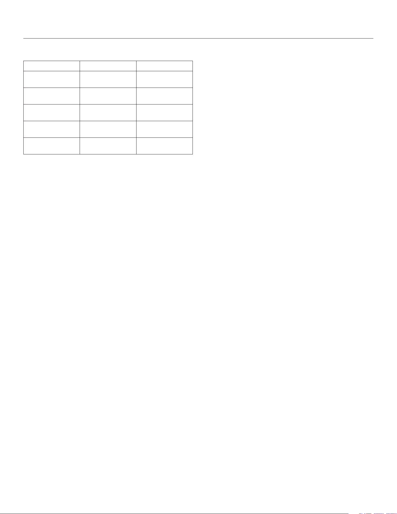
2.1 Heating Specications
Natural Gas Propane
Maximum
Input Rating
49,500 Btu/h
(14.51 kW)
49,500 Btu/h
(14.51 kW)
Minimum
Input Rating
18,500 Btu/h
(5.4 kW)
18,500 Btu/h
(5.4 kW)
Manifold Pressure
(High)
3.8” WC
(0.95 kPa)
11” WC
(2.74 kPa)
Manifold Pressure
(Low)
1.1” WC
(0.27 kPa)
2.9” WC
(0.72 kPa)
Orice Sizes (DMS) Center: 2.70mm
Sides: #54
Center: 1.75mm
Sides: #66
2.1.1 Altitude Adjustment
This appliance may be installed at higher altitudes. Please refer to
National Fuel Gas Code ANSI Z223.1/NFPA 54, CSA-B149.1 Natural
Gas and Propane Installation Code, local authorities, or codes having
jurisdiction in you area regarding derate guidelines.
2.1.1.1 US Installations
Refer to the American Gas Association guidelines for the gas designed
appliances derating method. For elevations above 2,000’ (610m),
input ratings are to be reduced by 4% for each 1,000’ (305m) above
sea level.
2.1.1.2 Canadian Installations
When the appliance is installed at elevations above 4,500’ (1,372m),
the certied high altitude rating shall be reduced at the rate of 4% for
each additional 1,000’ (305m).
2.2 Electrical Specications
• The junction box in this appliance requires 120VAC, 60Hz, and 6
Amps.
• Verify the household breaker is shut o prior to working on any
electrical lines.
• The AC power supply to this appliance must be hot at all times
and shall not have a switch installed in it.
#BHM-44 R.1 August 2020 Hussong Mfg. Co., Inc. • Kozy Heat Fireplaces SPECIFICATIONS 9
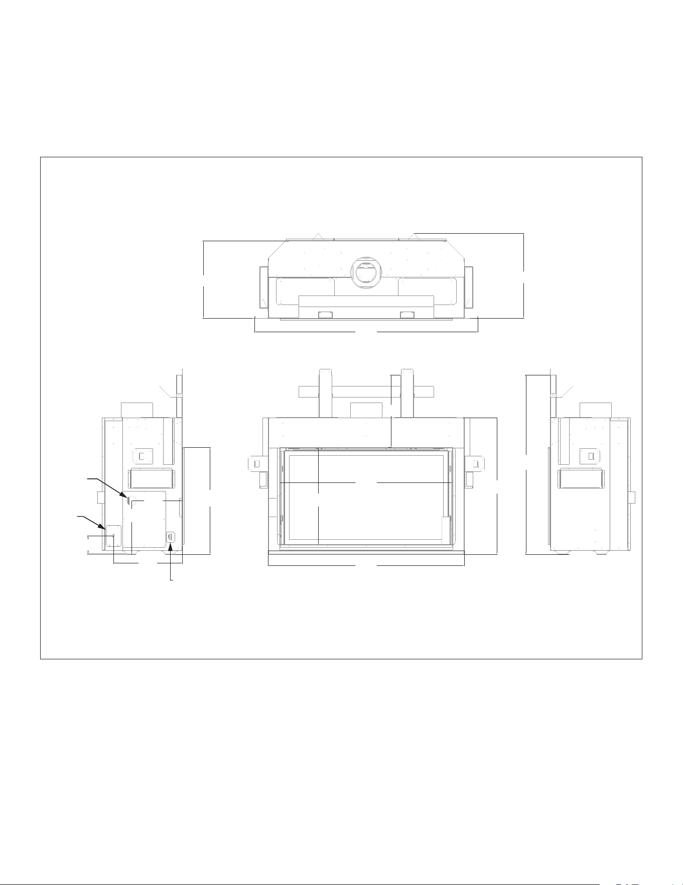
2.3 Appliance Dimensions
Figure 2.1, BHM-44 Dimensions
20”
(508mm)
575⁄8”
(1463mm)
22”
(558mm)
18
¾”
(477mm)
46
¼”
(1174mm)
35
¼”
(895mm)
44
7⁄16”
(1129mm)
24
7⁄8”
(632mm)
50
5⁄8”
(1286mm)
4
¾”
(120mm)
13¾”
(349mm)
17
11⁄16”
(450mm)
27
½”
(698mm)
13
1⁄16”
(332mm)
TOP VIEW
RIGHT SIDEFRONT VIEWLEFT SIDE
Gas Line
Access Hole
Electrical
Access
Power Vent Wire Harness Hole
(see KPV manual for more information)
10 SPECIFICATIONS Hussong Mfg. Co., Inc. • Kozy Heat Fireplaces #BHM-44 R.1 August 2020
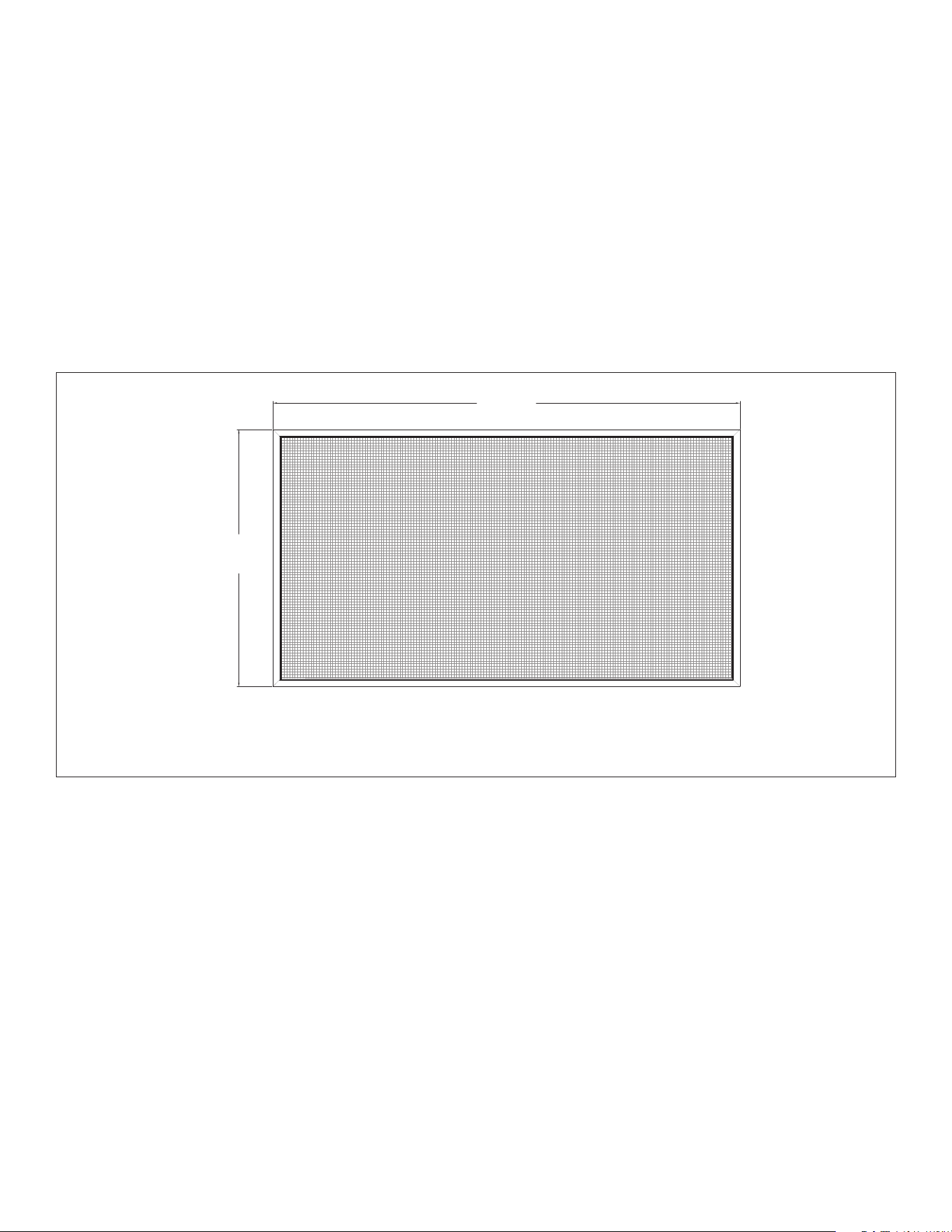
2.4 Safety Barrier Screen Dimensions
WARNING: A safety barrier designed to reduce the risk of burns from the
hot viewing glass is provided with this appliance and shall be installed
for the protection of children and other at-risk individuals.
If the safety barrier screen becomes damaged, the barrier shall be
replaced with Hussong Mfg. Co., Inc. barrier for this appliance.
For installation instructions, refer to Section 4.2 Safety Barrier
Installation on page 35.
Figure 2.2, Safety Barrier Screen Dimensions
433⁄8”
(1102mm)
23
7⁄8”
(606mm)
Safety Barrier Screen (only)
BH44-ES
#BHM-44 R.1 August 2020 Hussong Mfg. Co., Inc. • Kozy Heat Fireplaces FRAMING 11
3.0 FRAMING
3.1 Installation Planning
This appliance oers several design options for managing the heat
produced by this replace.
Read all documentation for your specic installation
and design options prior to appliance installation.
• Standard Installation will be outlined in this manual in sections
marked ‘standard installation’ and must be followed if no design
options (vented cavity and Komfort Zone Kit) are to be used. The
replace chamber and ceiling minimum height must be 88”
(2235mm) for all design options.
If planning a standard installation with the use of a heat
transfer kit(s) (HTK-EXT and/or HTK-INT), the standard framing
dimensions will still apply.
• Heat Transfer Kit(s) allows you to transfer heat to a specic area
inside your home (interior) or directly outside (exterior). This
appliance can have (2) heat transfer kits installed at the same
time. It can be up to two of the same heat transfer kits, or a
combination of interior and exterior kits. See the HTK-EXT and/
or HTK-INT manuals for further information.
If you are planning a standard installation with the use of an
exterior and/or interior kit, the minimum dimensions listed in
this section will apply for your framing installation. You will still
need to remove the cover plates as instructed in Section 3.8 on
page 20. If you are installing a heat transfer kit with the use
of a KZK or vented cavity option, the minimum requirements
applicable to those options must be adhered to.
• Vented Cavity oers the option to leave a minimum sized
opening in the replace cavity, allowing for heat reduction above
the replace. This option allows for combustible facing materials
above the replace, heat reduction for a TV mounted above the
replace, and lower mantel clearances. See Section 3.9 Vented
Cavity and Komfort Zone Kit Installation on page 21.
All vented cavity options have the same minimum chamber
and ceiling dimension requirements as the standard installation
dimensions in this section. The replace chamber and ceiling
minimum height must be 88” (2235mm) for all design
options. Reference Section 3.9 Vented Cavity and Komfort Zone
Kit Installation on page 21.
• Komfort Zone Kit oers the option to redistribute radiant heat
through plenum(s). This option allows for combustible facing
materials above the replace, heat reduction for a TV above the
replace, and lower mantel clearances. See Section 3.9 Vented
Cavity and Komfort Zone Kit Installation on page 21.
If installing a Komfort Zone Kit (#KZK-045 or #KZK-1510A),
the framing requirements may be dierent than the standard
dimensions listed in this section. Please reference the manual
included with your kit before completing all replace framing
and other installation considerations.
• Kozy Power Vent is a fan-powered mechanical draft vent system
(horizontal terminations only) for use with any of the design
options listed above. It is easier to convert the replace for use
with the #KPV before framing in the replace. If you convert the
replace for use with the #KPV after replace installation, you will
have to remove the control board. See Section 8.5 Control Board
Access, Removal and Installation on page 53 for access to the
control board before and after installation.
• If planning to convert to propane, it is easier to complete the gas
conversion before framing in the replace. See the #LCK-BH44-
SPB manual for complete conversion instructions. If you convert
the replace to propane after replace installation, you will have
to remove the control board. See Section 8.5 Control Board
Access, Removal and Installation on page 53 for access to the
control board before and after installation.
Please read the instructions in this manual carefully for your
specic installation.
3.1.1 Appliance Placement Considerations
WARNING: Due to high temperatures, the appliance should be located
out of trac and away from furniture and draperies.
• This appliance must be installed on a level surface capable of
supporting the replace and venting. Determine your vent
requirements before framing your appliance.
If installing #KPV Kozy Power Vent, please reference the manual
included with the kit.
• This replace may be installed in a bedroom.
• Please be aware of the large amount of heat this replace will
produce when determining a location.
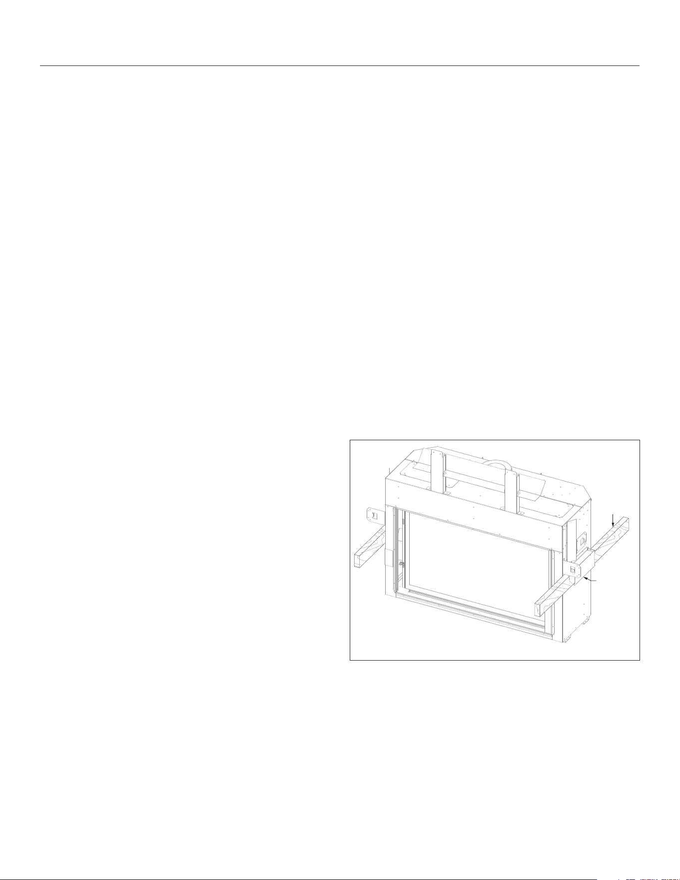
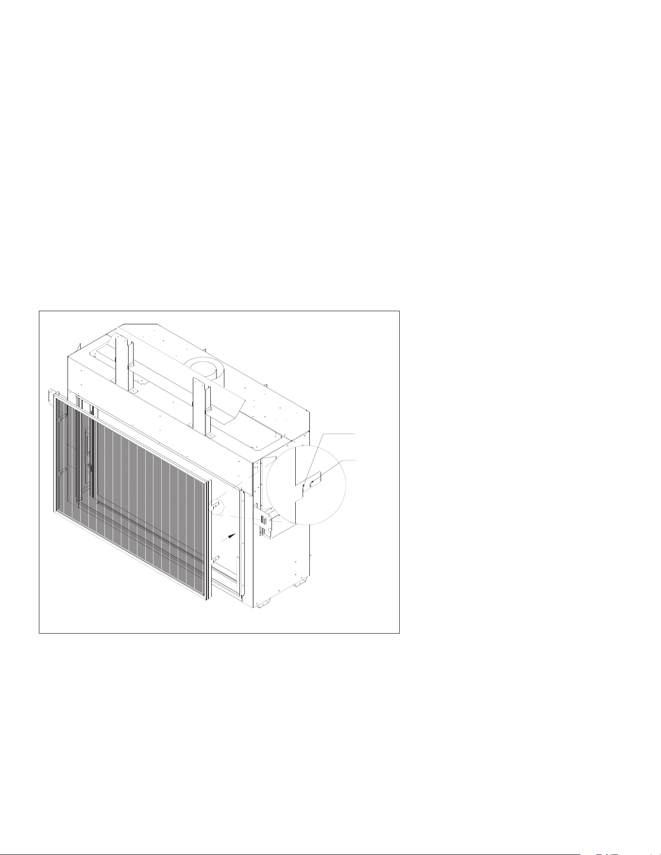
3.1.2 Moving the Appliance
This appliance is heavy. We recommend a team lift when moving,
placing, and positioning the appliance.
On both sides of the appliance, there are lift handles that allow a
hand lift (no sharp edges), or allow a 2” x 4” piece of lumber to be
inserted inside the lift handles, as shown in Figure 3.1.
Figure 3.1, Lift Handles
2 x 4”
Lift handle
12 FRAMING Hussong Mfg. Co., Inc. • Kozy Heat Fireplaces #BHM-44 R.1 August 2020
Stand-off
flange
Nailing flange
installed
Nailing flange
as shipped
Nailing flange
installed
Framing stud
Nailing flange
Stand-off flange
Nailing flange
Framing stud
3
½” (89mm)
clearance
3.2 Nailing Flange Assembly
and Installation
CAUTION: Never permanently remove these assemblies from the
replace—they must be secured regardless of nish material used.
The nailing anges MUST BE INSTALLED for all applications.
1. Remove (2) nailing anges from the right and left side of the
replace.
2. Align nailing anges with holes on the outside corners of
replace, with the stand-o anges on the nailing anges facing
away from the replace.
3. Secure the nailing anges to the replace with screws (provided)
through the slots in nailing anges.
4. Bend perforation on nailing ange until parallel with replace
face. Do not bend toward replace face.
5. UNTIL ALL FRAMING REQUIREMENTS ARE COMPLETED:
Position framing stud against the small stand-o (located on
backside of nailing ange). Secure with nails or screws.
• When installed, the nailing anges provide the minimum
3½” (89mm) clearance from the sides of the replace to
framing.
Figure 3.2, Nailing Flange Installation
Top View
Front View
Front View
Back View
ALL DESIGN OPTIONS INSTALLATION
#BHM-44 R.1 August 2020 Hussong Mfg. Co., Inc. • Kozy Heat Fireplaces FRAMING 13
Figure 3.3, Standard Installation for Stand-o Assembly and Header Heat Shield
3.3 Stand-o Assembly and
Header Heat Shield
WARNING: The stand-o assembly and header heat shield MUST BE
INSTALLED in order to maintain clearance requirements for vented
cavity and standard installation. These clearances must be maintained.
See Section 3.9.2 on page 22 for requirements for KZK-1510A or KZK-
045 installations.
The stand-o assembly provides:
• Minimum distance to header
• Contact point for non-combustible material above the replace
• Attachment for the header heat shield
1. Locate the stand-o assembly and header heat shield on top of
the replace, as shipped.
2. Form the header heat shield as shown.
3. Attach the header heat shield to the stand-o assembly, (4)
screws total (provided in the components part packet).
4. Align the holes on the bottom of the stand-o assembly with the
holes on top of the replace. Secure with (4) screws total.
5. Remove and save screws securing the back stand-o brackets.
Form the back stand-o heat shields as shown. Secure using
screws previously removed.
STANDARD AND VENTED CAVITY
INSTALLATIONS ONLY
14 FRAMING Hussong Mfg. Co., Inc. • Kozy Heat Fireplaces #BHM-44 R.1 August 2020
3.4 Clearances to Combustibles
Table 3.1, Minimum Appliance Clearances to Combustible Material
From appliance top stand-o brackets 0” 0mm
From appliance left and right stand-o brackets 0” 0mm
From appliance back stand-o brackets 0” 0mm
From appliance corners 2” 51mm
From appliance front 36” 914mm
Fireplace nishing edge to adjacent sidewall 6” 152mm
Fireplace nishing edge to 3/4” (19mm) mantel trim 16” 407mm
Mantel 6” (152mm) deep from replace nishing edge 19-1/2” 496mm
Minimum rough opening height 46-1/4” 1175mm
Minimum rough opening width 57-5/8” 1468mm
Minimum rough opening depth 22” 558mm
Minimum height of replace enclosure 88” 2235mm
Base of the replace to ceiling 88” 2235mm
Fireplace nishing edge to ceiling 60-1/2” 1537mm
Any horizontal venting within the replace enclosure 16-1/4” 412mm
Figure 3.4, Clearance to Combustibles
575⁄8”
(1468mm)
22”
(558mm)
2”
(51mm)
22
½”
(572mm)
44¼”
(1123mm)
2”
(51mm)
57
5⁄8”
(1463mm)
88½”
(2248mm)
62
½”
(1588mm)
575⁄8”
(1468mm)
22”
(558mm)
2”
(51mm)
Corner Installation
Typical Horizontal Installation Typical Vertical Installation
ALL DESIGN OPTIONS INSTALLATION
#BHM-44 R.1 August 2020 Hussong Mfg. Co., Inc. • Kozy Heat Fireplaces FRAMING 15
3.5 Rough Framing
Dimensions outlined below are the same for all design options.
WARNING: Provide adequate clearance in front of the replace for
barrier removal, component access, gas line installation, service
access, etc.
CAUTION: Cold air transfer area. The replace enclosure must comply
with all clearances as outlined in this manual, and be constructed
in compliance with local building codes. Outside walls should be
insulated to prevent cold air from entering room.
• Rough framing dimensions for standard installation should allow
for wall covering thickness and replace facing materials. Adjust
rough opening size as necessary to maintain minimum clearance
requirements.
• Floor protection in front of the replace is not required.
Combustible material may be used if installing a hearth
extension. Consider the thickness of the hearth extension
nishing material if building a replace platform. The hearth may
be ush with the bottom nishing edge.
• The bottom of the replace must be placed directly on a wood
or non-combustible surface (not linoleum or carpet). If this
appliance is to be installed directly on carpeting, tile, or other
combustible material other than wood ooring, this appliance
shall be installed on a metal or wood panel extending the full
width and depth of the appliance.
• This replace may be elevated o the oor, provided it is
properly supported by framing materials and maintains ceiling
clearances. If installed above oor level, a solid, continuous
platform must be constructed below the replace.
• If masonry (optional) is to be used, prepare the foundation
necessary for the full masonry load.
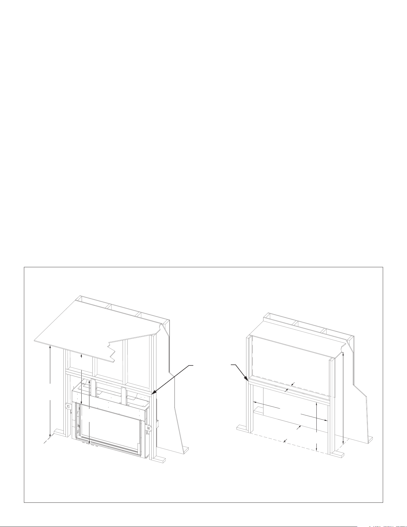
3.5.1 TV Recess Construction
WARNING: All clearances to venting must be maintained.
Mounting a television above a replace is a common practice. Mantel
depth, ceiling heights, and wall and mantel construction material all
aect television surface temperatures. Most television manufacturers
specify in their instructions that a television should not be installed
on, near, or above a heat source.
Television location rests solely on the homeowner. It is the home
owner’s responsibility that the preferred TV mounting and mantel
design will not exceed the listed maximum operation temperature of
their electronic goods.
Tests performed determined that television surface temperatures
did not exceed 150°F (66°C) when a 4¼” (108mm) deep recess is
constructed above the replace.
Figure 3.5, Standard Installation Rough Opening Dimensions and TV Recess Construction
60½”
(1537mm)
88”
(2235mm)
46
¼”
(1175mm)
575⁄8”
(1463mm)
22”
(558mm)
4
¼”
(108mm)
88”
(2235mm)
46
¼”
(1175mm)
Double horizontal
header
Ceiling/Fireplace enclosure top
Ceiling/Fireplace
enclosure top
TV Recess
ALL DESIGN OPTIONS INSTALLATION

16 FRAMING Hussong Mfg. Co., Inc. • Kozy Heat Fireplaces #BHM-44 R.1 August 2020
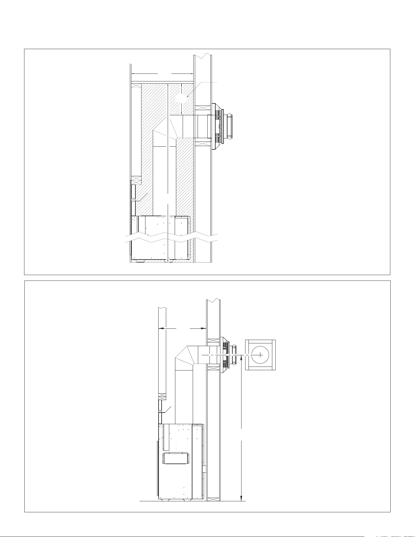
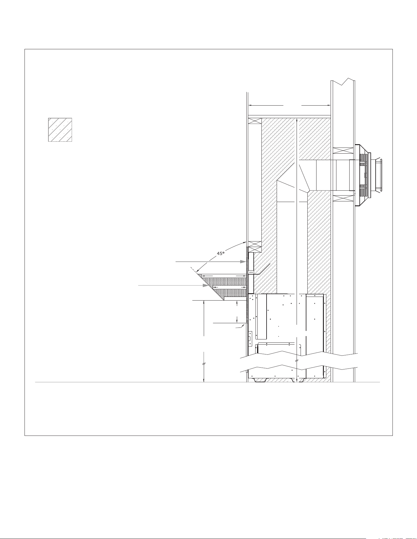
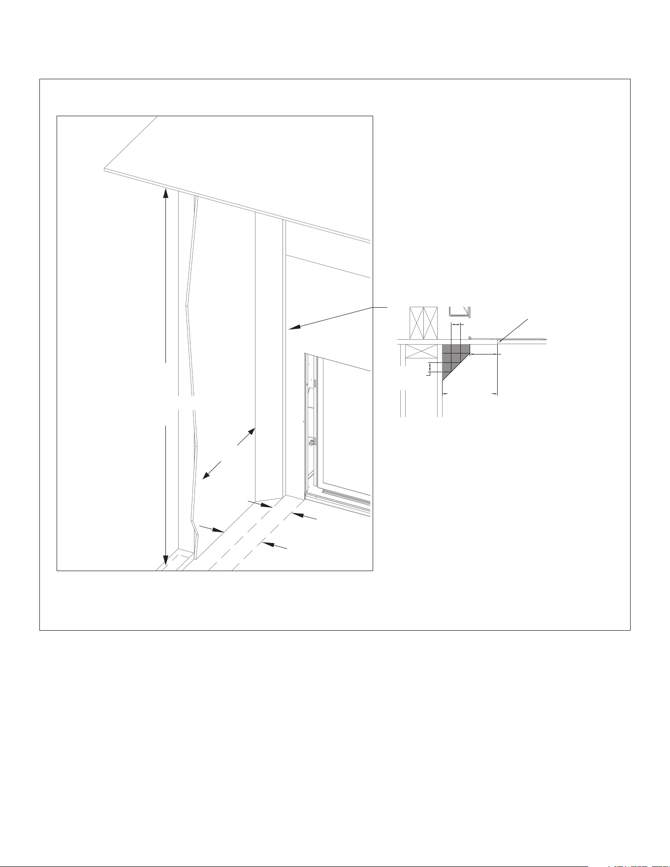
3.6 Natural Draft Vent Termination
Rough Framing
The following information applies to all standard, KZK, and vented
options when venting with natural draft. If using Kozy Power Vent
#KPV, please reference the manual included with the kit.
3.6.1 Vent Termination Framing Requirements
This is a cold air transfer area. The replace enclosure must comply
with all clearances as outlined in this manual, and be constructed
in compliance with local building codes. Outside walls should be
insulated to prevent cold air from entering room.
Exterior vent termination location must be in compliance with
Section 6.2 Minimum Natural Draft Vent Termination Clearances on
page 42.
IMPORTANT - METAL FAB VENT SYSTEM : When installing Metal Fab
vent pipe, an adapter must be used. This will increase the minimum
height for the center of the vent pipe by 3-1/4” (83mm) when framing
the wall pass through for horizontal terminations.
3.6.1.1 Clearances
• A minimum of 1” (25mm) clearance on all sides of the vertical
vent pipe must be maintained.
• A minimum of 1” (25mm) clearance from the top surface on the
horizontal pipe must be maintained.
• A minimum of 1” (25mm) clearance on the sides and bottom
surfaces on the horizontal pipe must be maintained.
• A minimum of 16-1/4” (412mm) clearance from any venting to
the enclosure top is required in all horizontal vent termination
installations. The horizontal pipe after the wall pass-through
must maintain a 1” (25mm) clearance to combustibles on all
surfaces of the pipe. See Figure 3.6 on page 17.
3.6.2 Vertical Terminations
Follow vent pipe manufacturer’s installation instructions for vertical
terminations.
• Attic insulation shields may be insulated using unfaced
insulation products listed as non-combustible per ASTM E 136.
3.6.3 Horizontal Terminations
WARNING: Do not recess the vent cap into wall or siding.
IMPORTANT: Horizontal vent sections require 1/4” (6mm) rise for every
12” (305mm) of travel for natural draft applications.
Wall thimble products that comply with the required 1” (25mm) top
clearance to combustibles must be installed for all horizontal vent
runs that pass through interior or exterior walls. These wall thimble
products may be insulated using unfaced insulation products listed as
noncombustible per ASTM E 136.
Elbows listed with approved vent systems for this appliance vary in
vertical length. Please consult the vent manufacturer’s instructions
to determine the elbow dimension used for installation. Adjust the
wall pass-through rough opening dimensions to maintain clearance
requirements.
3.6.4 Wall Pass Through Framing Instructions
1. Measure from oor level of the replace to the center of where
the vent pipe will penetrate the wall. The dimension in Figure 3.7
on page 17 is used with a Simpson DuraVent elbow.
2. Cut and frame an opening in the wall to allow the vent system to
run level through the wall pass-through.
3. Follow the vent pipe manufacturer’s installation instructions for
natural draft vent installation.
• Rigid pipe dimensions are tested with listed Simpson Duravent
pipe. Other manufacturers product dimensions may vary.
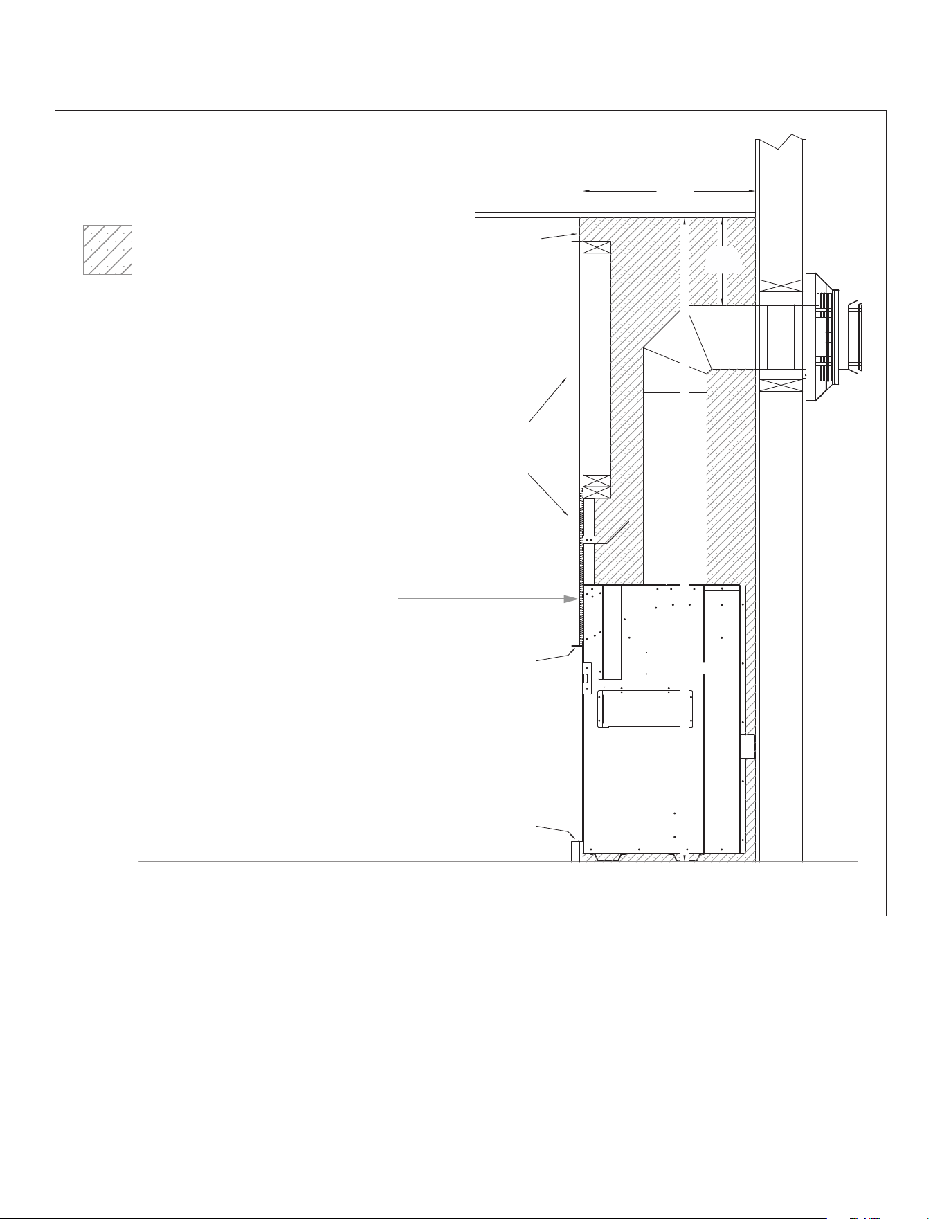
#BHM-44 R.1 August 2020 Hussong Mfg. Co., Inc. • Kozy Heat Fireplaces FRAMING 17
Figure 3.6, Vent Termination Minimum Framing Clearances
22”
(558mm)
67
¾”
(1721mm)
Natural gas and propane
Natural draft minimum horizontal terminations
22”
(558mm)
88”
(2235mm)
16¼”
(412mm)
16¼” (412mm) Minimum clearance
between any venting and the top
of enclosure is required in all
horizontal vent termination
installations
Figure 3.7, Vent Termination Minimum Framing Dimensions
ALL DESIGN OPTIONS INSTALLATION
ALL DESIGN OPTIONS INSTALLATION
18 FRAMING Hussong Mfg. Co., Inc. • Kozy Heat Fireplaces #BHM-44 R.1 August 2020
SIDE OF
FIREPLACE
FRONT OF
FIREPLACE
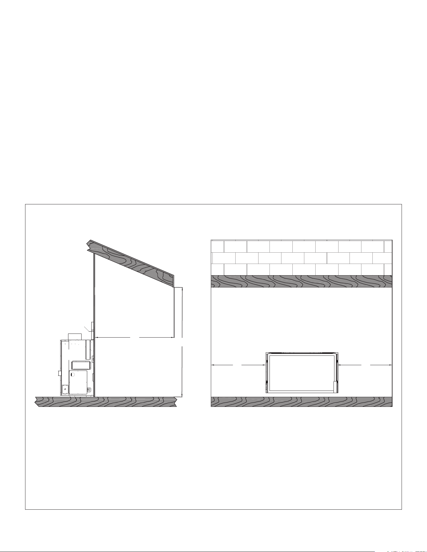
ROOF OVERHANG
A
B
CC
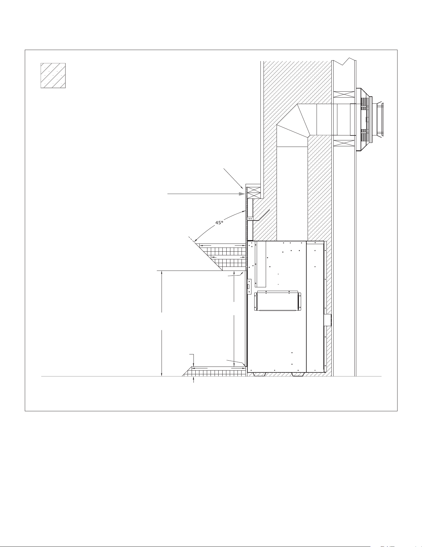
The overhang (A) must be a minimum of 1/2 or
greater of the roofline elevation (B) above the
base of the fireplace.
The width of the overhang to each side of the appliance (C)
must be a minimum of 1/2 or greater of the roofline elevation (B)
above the base of the fireplace.
EXAMPLE: If roofline (B) is 10’ (3m) above the base of fireplace, the overhang (A) must be
5’ (1.5m) or greater. The width of the overhang to EACH side of the fireplace (C) must be 5’ or greater.
Figure 3.8, Outdoor Covered Fireplace Install - 1
3.7 Outdoor Covered Fireplace Installation
An outdoor covered replace installation allows a replace to be
installed in an outdoor covered area, where the appliance is protected
from direct precipitation.
Based on your design options and installation choices (standard
installation, vented cavity, or Komfort Zone Kit), follow your specic
requirements pertaining to your installation.
Follow the instructions and illustrations on this page and the
following page for installation procedures.
3.7.1 Safety Screen Barriers
Hussong Mfg. Co., Inc. highly recommends to use black painted
safety barriers in outdoor installations. Other screen barriers that
incorporate a plated or patina nish are highly susceptible to
oxidation and discoloration.
3.7.2 Requirements
• The continuous insulated building envelope and weatherproof
membrane are not to be interrupted by replace installation. See
Figure 3.9 on the following page.
• Fireplace operation is approved from 40°F to 110°F.
• All wiring connections shall be in accordance with outdoor
requirements of NECA NFPA 70.
• All clearances and requirements in your appliance manual must
be adhered to.
ALL DESIGN OPTIONS INSTALLATION

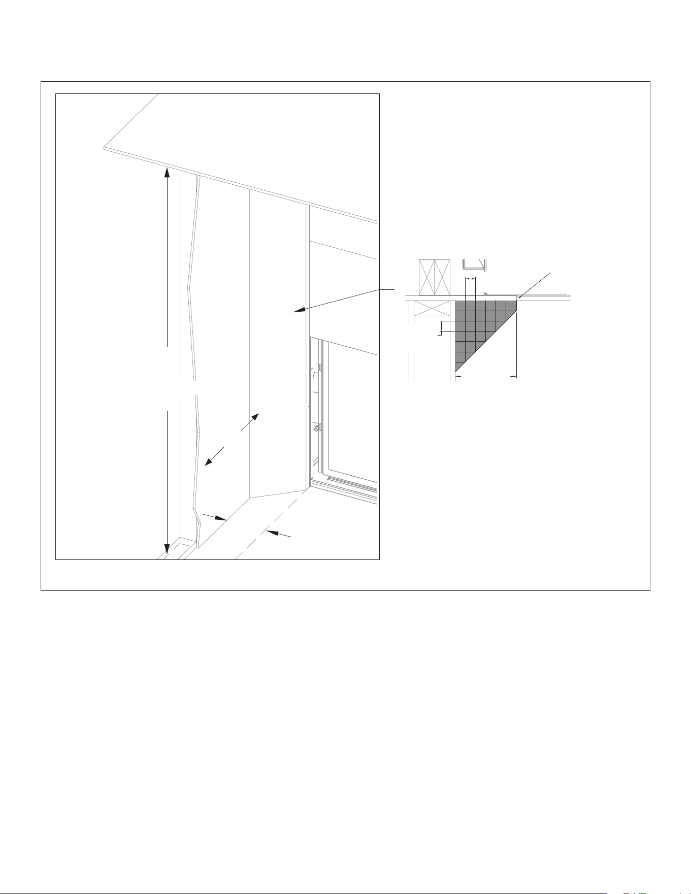
#BHM-44 R.1 August 2020 Hussong Mfg. Co., Inc. • Kozy Heat Fireplaces FRAMING 19
Continuous insulated building
envelope and weatherproof
membrane are not interrupted
by replace installation
Free standing structure
(weatherproof enclosure)
Minimum weatherproof
overhang in front and sides
Minimum weatherproof
overhang in front and sides
Minimum weatherproof
overhang in front and sides
Minimum weatherproof
overhang in front and sides
INSIDE
OUTSIDE
INSIDE
Figure 3.9, Outdoor Covered Installation 2 (your replace may look dierent than the one shown)
3.7.3 Outdoor Covered Fireplace Installation (continued)
ALL DESIGN OPTIONS INSTALLATION
20 FRAMING Hussong Mfg. Co., Inc. • Kozy Heat Fireplaces #BHM-44 R.1 August 2020
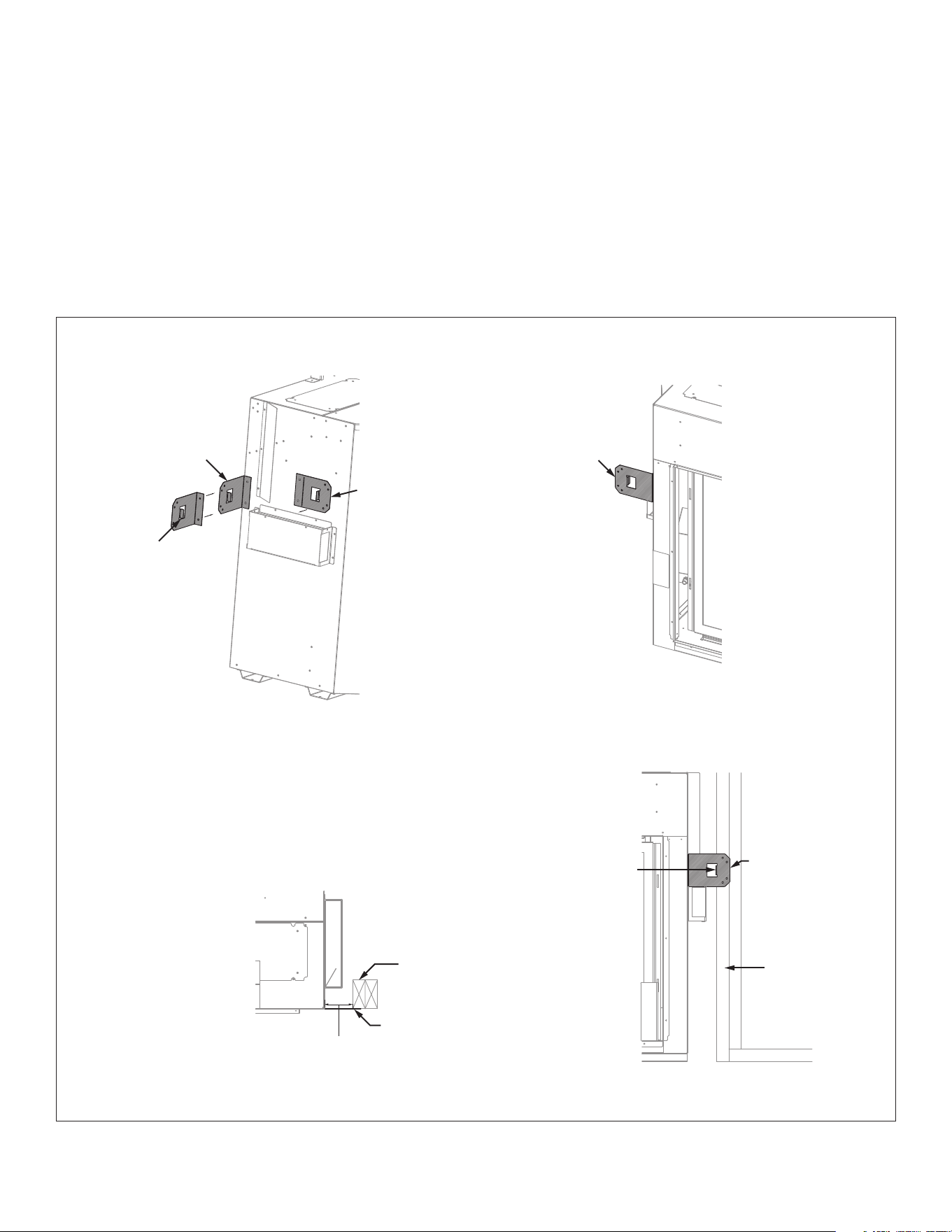
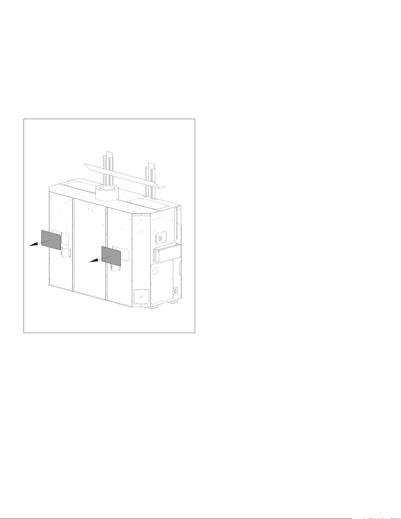
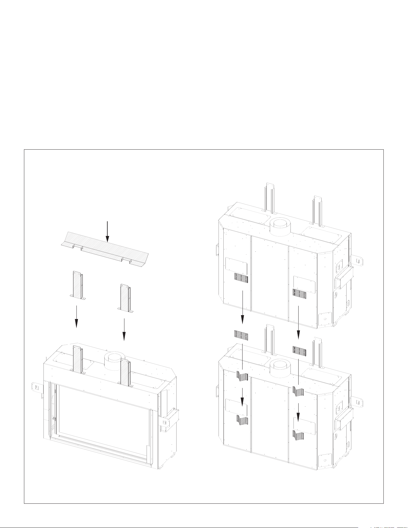
3.8 Exterior and Interior Heat
Transfer Kit Cover Plates
Figure 3.10 shows removal of the Heat Transfer Kit cover plates. There
are (2) square cover plates located on the rear of the outer shell of the
appliance. This appliance can have (2) Heat Transfer Kits installed at
the same time. It can be up to two of the same heat transfer kit or a
combination of interior and exterior kits.
Remove (1) square cover plate per kit, up to (2) kits may be used.
See heat transfer kit manuals (HTK-EXT/HTK-INT) for more information
Figure 3.10, Heat Transfer Kit Cover Plate Removal
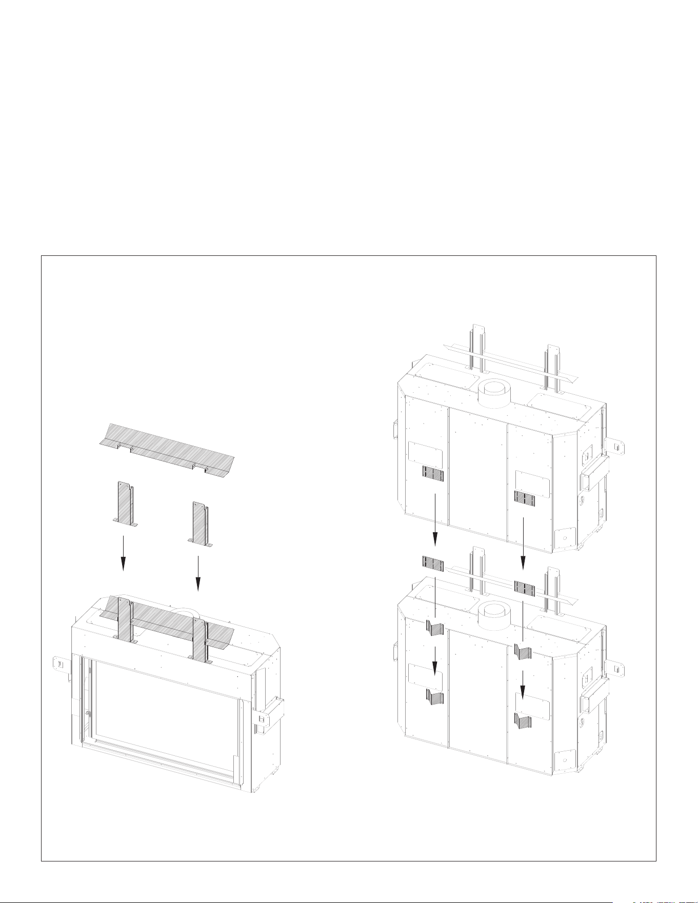
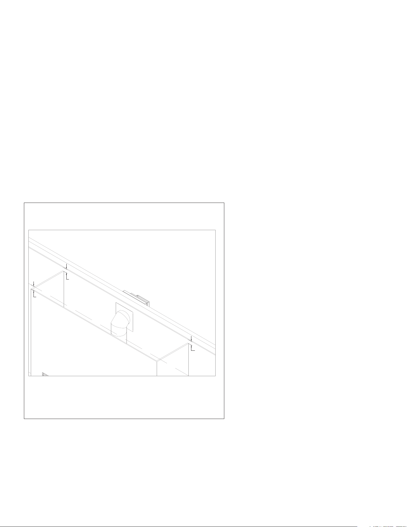
#BHM-44 R.1 August 2020 Hussong Mfg. Co., Inc. • Kozy Heat Fireplaces FRAMING 21
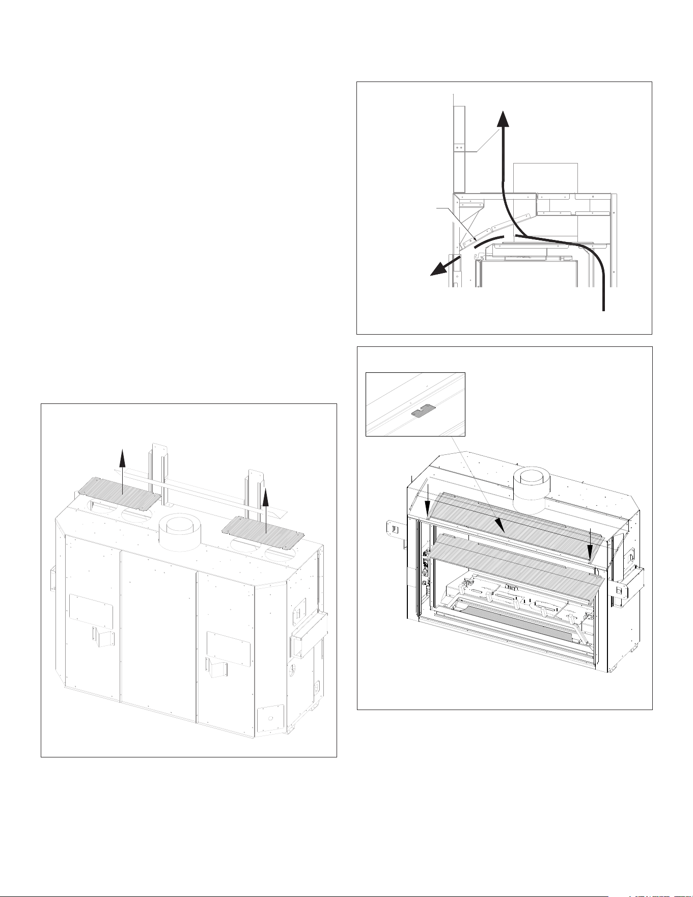
Remove (2) cover plate for a Komfort Zone Kit or
vented cavity options for the front or top vent cavity
Figure 3.11, Cover Plate Removal
3.9 Vented Cavity and Komfort
Zone Kit Installation
3.9.1 Komfort Zone Kit and Vented
Cavity Preparation Overview
The Komfort Zone Kit and Vented Cavity design options have specic
framing requirements, mantel requirements, and exterior trim
dimensions. The appliance convection bae and outer shell plates
must be removed for heat distribution required by cavity framing
designs.
• All framing requirements in Section 3.5 Rough Framing on page
15 will apply to the vented cavity and KZK installation.
• All minimum required dimensions must be maintained after all
nishing materials are installed.
1. Remove the (2) top cover plates that correspond to the vented
cavity options for the front or top vented cavity. See Figure 3.11.
If planning to install a Komfort Zone kit, these (2) cover plates
will also have to be removed. See the #KZK-045 or #KZK-1510A
manual for further replace preparation.
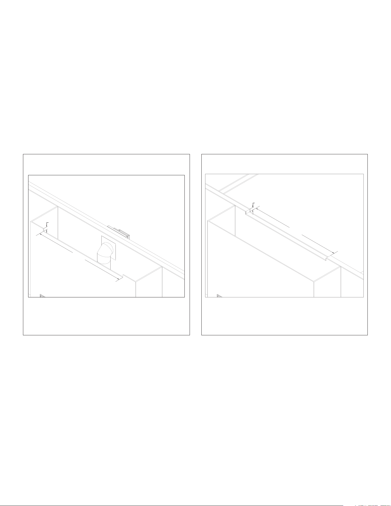
2. Remove the convection bae from the appliance. The bae is
secured by (4) screws behind the upper edge of the replace
opening. See Figure 3.13. Recycle this panel as it is no longer
needed.
Convection
baffle to be
removed
Convection airflow
with baffle in place
Convection airflow
with baffle removed
Figure 3.12, Air Flow inside Appliance with Convection Bae Removed
Figure 3.13, Convection Bae Removal
22 FRAMING Hussong Mfg. Co., Inc. • Kozy Heat Fireplaces #BHM-44 R.1 August 2020
3.9.2 Komfort Zone Kit Fireplace
Preparation Overview
The header heat shield can be removed to ease Komfort Zone Kit
installations.
The top stando assembly must be installed for minimum distance to
header and a contact point for non-combustible material above the
replace. The back stand-os must be installed.
1. Remove (4) screws securing the header heat shield to the stand-
o assembly.
2. Discard header heat shield.
3. Align the holes on the bottom of the stand-o assembly with the
holes on top of the replace. Secure with (4) screws total.
4. Remove and save screws securing the back stand-o brackets.
Form the back stand-o heat shields as shown. Secure using
screws previously removed.
Figure 3.14, Komfort Zone Kit Installation for Stand-o Assembly
Discard header heat shield
KZK INSTALLATIONS ONLY
#BHM-44 R.1 August 2020 Hussong Mfg. Co., Inc. • Kozy Heat Fireplaces FRAMING 23
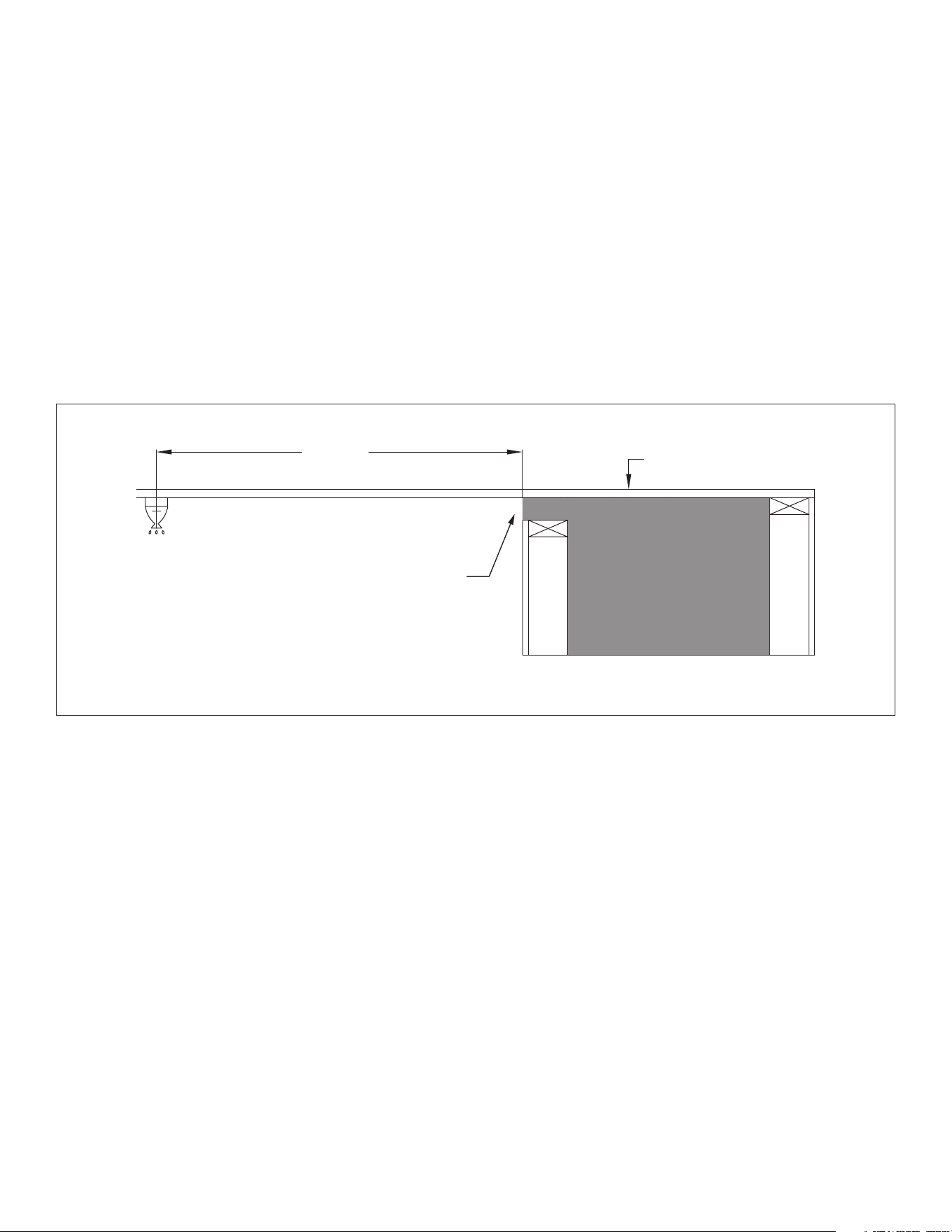
60”
(1524mm)
MIN
Ceiling
Air Discharge Opening
Figure 3.15, Clearance from Air Discharge Opening to Sprinkler Head
3.9.3 Clearance to Sprinkler
• In a situation where a sprinkler head is installed within the
proximity of a vented cavity air discharge opening, Figure 3.15
MUST be followed.
• The distance between a sprinkler head and discharge opening
cannot be less than 60” (1524mm) in length at every point from
the origin of the discharge opening. You must also verify the
sprinkler head sensor is set to the proper heat setting so it does
not activate when the room heats up from the replace being
operated normally.
• Please follow local building codes to determine what
temperature setting is relevant for your installation.
VENTED CAVITY INSTALLATIONS ONLY
24 FRAMING Hussong Mfg. Co., Inc. • Kozy Heat Fireplaces #BHM-44 R.1 August 2020
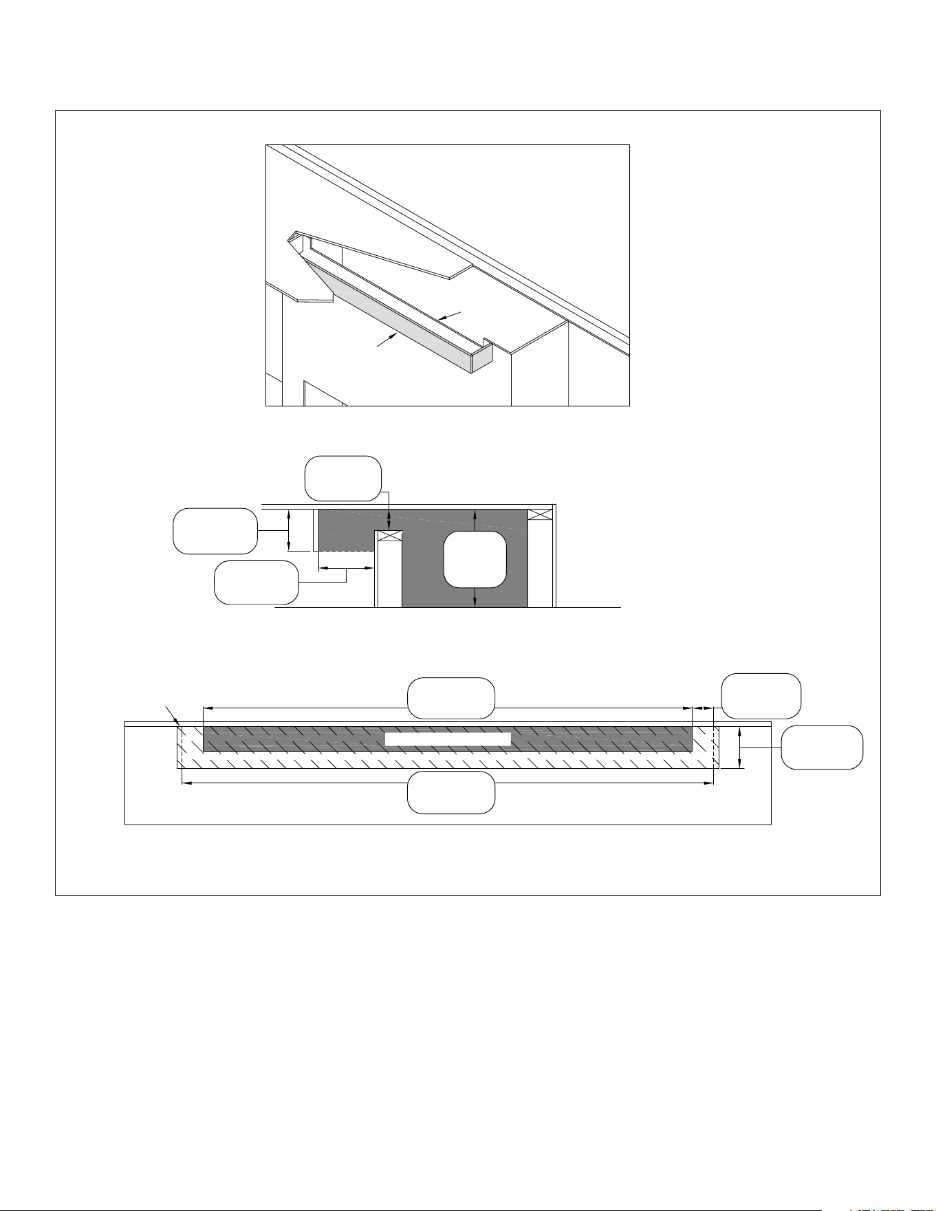
3.9.4 Front Vented Cavity Option
NOTE: This vented cavity option allows the use of 19 gauge or less
hardware mesh that is 1/2” x 1/2” to prevent any items from entering
the vented cavity. This hardware mesh is optional and the only
approved item for use within the air discharge opening.
WARNING: Do NOT cover or place any items in the area of the air
discharge opening. Failure to comply with these instructions could
create a re hazard. Grilles and louvers are not allowed in the discharge
opening.
WARNING: Ensure air ow within the air discharge opening is not
restricted in any way.
WARNING: Enclosure measurements must maintain minimum framing
specications as outlined in Section 3.5 Rough Framing on page 15.
Minimum dimensions for the air discharge MUST BE maintained after
all nishing materials are installed.
These are minimum dimensions shown for the air discharge
opening, and the opening may be increased, if desired, as long
as all requirements are followed. It is recommended to limit your
opening size for aesthetic purposes and to avoid items falling into the
enclosure.
• Figure 3.16 shows the minimum required dimensions for the
vent cavity air discharge opening. This single 3” (height) x 44”
(width) air discharge opening can be in either the front of the
replace chamber, so hot air exits into the room the replace is
installed, or the discharge opening can be in an adjacent room,
where the discharge opening would be located on the rear of
the replace chamber. See Figure 3.17 for rear opening.
Figure 3.17, Vented Cavity Rear to Adjacent Room InstallationFigure 3.16, Front Vented Cavity Installation
3”
(76mm)
44”
(1118mm)
Front vented cavity option with air discharge in front
Single 3” (76mm) height x 44” (1118mm) width air discharge minimum opening
3”
(76mm)
44”
(1118mm)
Front vented cavity option with air discharge in rear
Single 3” (76mm) height x 52” (1321mm) width air discarge minimum opening
VENTED CAVITY INSTALLATIONS ONLY VENTED CAVITY INSTALLATIONS ONLY
#BHM-44 R.1 August 2020 Hussong Mfg. Co., Inc. • Kozy Heat Fireplaces FRAMING 25
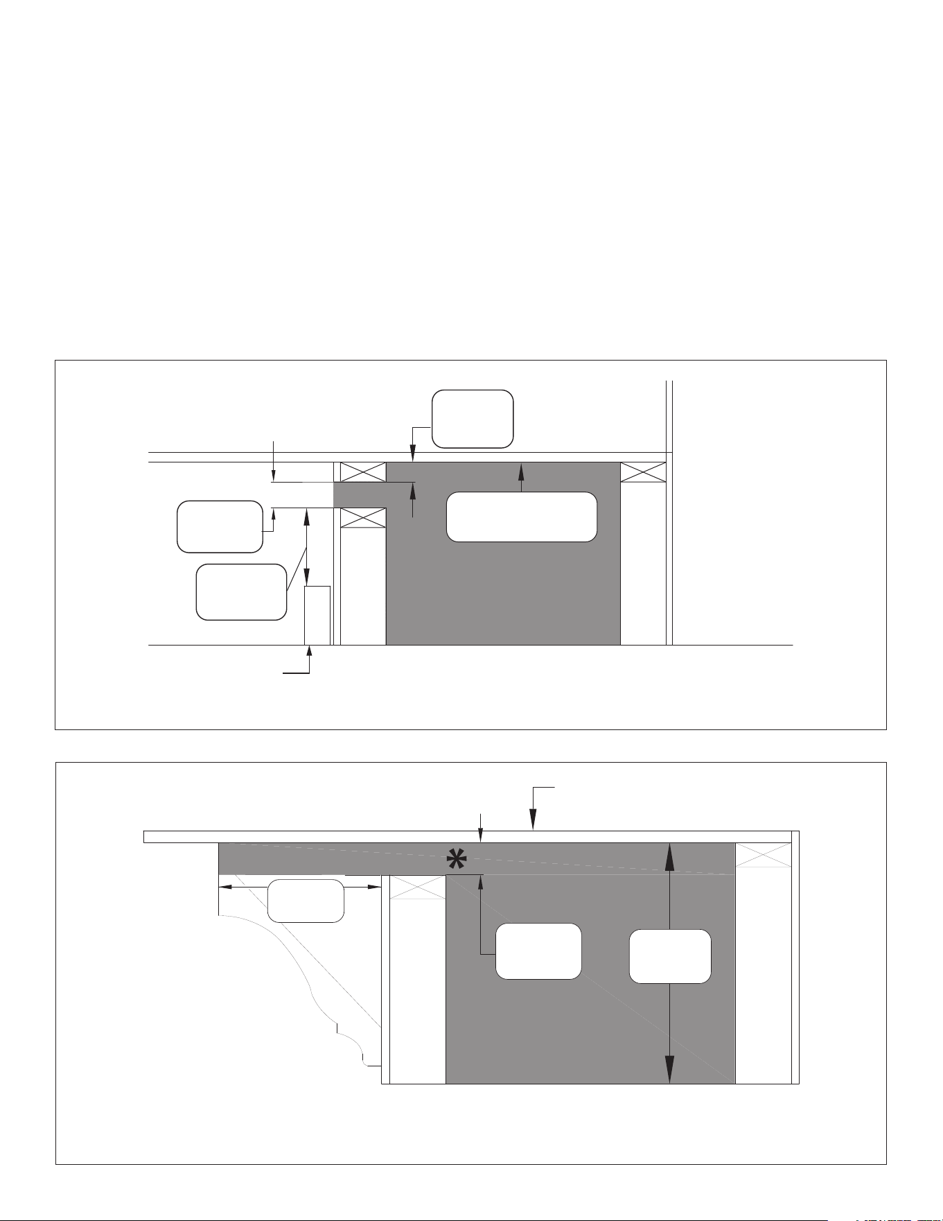
12”
(305mm)
88”
(2235mm)
3”
(76mm)
Air discharge
opening
*must maintain 3” (76mm) clearance for
full length of crown molding/trim projection
Enclosure
Ceiling
Min
Max
Min
Figure 3.19, Front Vented Cavity Crown Molding Installation
3.9.4.1 Front Vented Cavity Option
Alternative Installations
• Figure 3.18 shows an alternative installation method where you
cap o the replace cavity so the air discharge opening can be
located further down the replace chamber. 1-1/2” (38mm) is
the maximum drop for framing the air discharge opening to
the replace enclosure top. This avoids trapping heat in the
upper areas of the vented cavity enclosure. Framing the outlet
any lower than 1-1/2” (38mm) will cause over heating create a
re hazard. This installation method can alleviate any possible
concerns with paint discoloration from heat or dust.
• Figure 3.19 shows the installation of crown molding or similar
trim work that goes up to the edge of the air discharge opening.
12” (305mm) is the maximum length of the molding or trim
projection and you must maintain 3” (76mm) clearance for the
full length of crown molding/trim projection. This molding or
trim cannot decrease the minimum opening requirement.
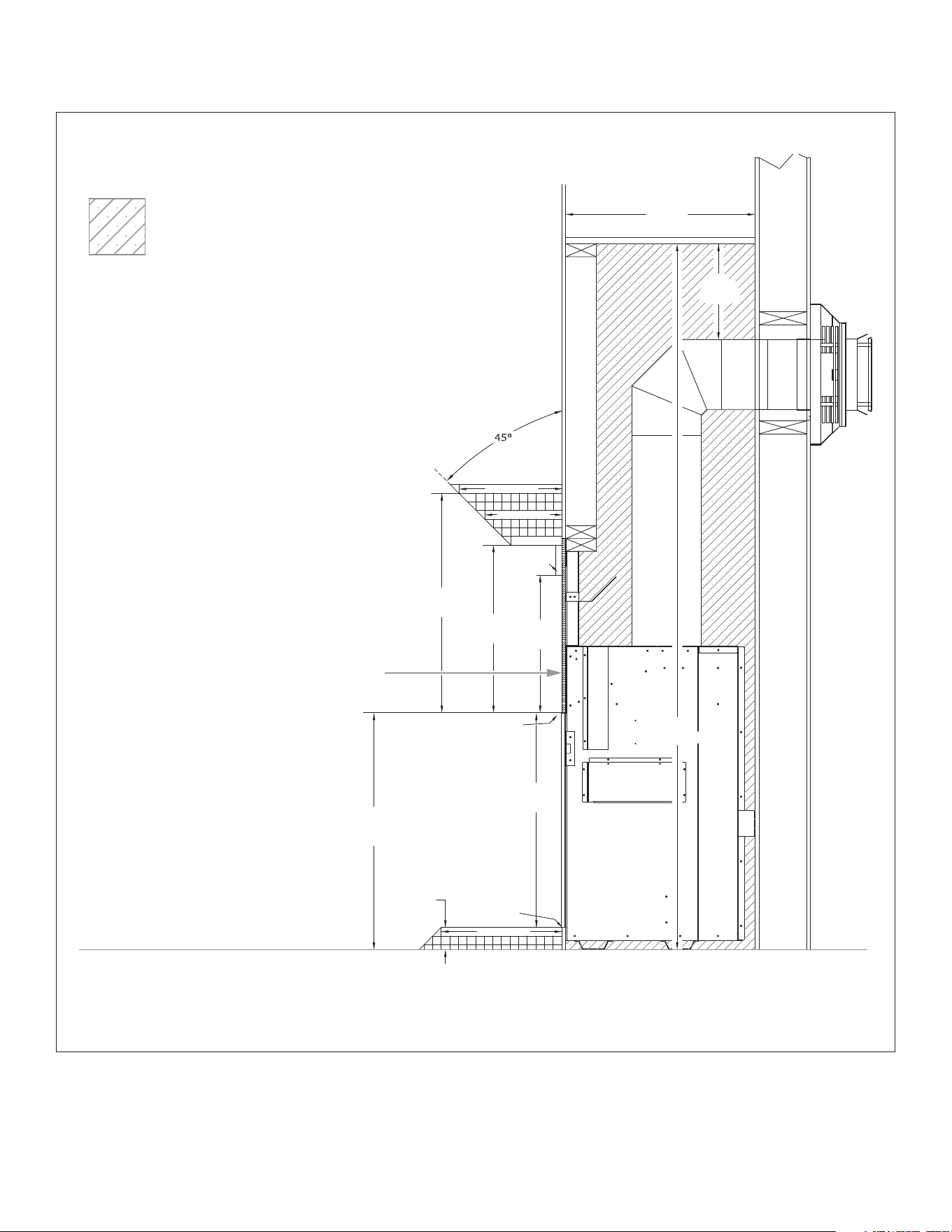
• Figure 3.20 on the following page shows an alternative
installation for the front vented cavity option with an air
discharge overhang in front of the air discharge opening. This
installation method can provide a means to visually hide the air
discharge opening.
Figure 3.18, Front Vented Cavity Alternative Installation
Enclosure top
must be installed
3”
(76mm)
6”
(152mm)
1
½”
(38mm)
Max
Min
Min
Ceiling
Wall mounted object
(picture frame, TV)
VENTED CAVITY INSTALLATIONS ONLY
VENTED CAVITY INSTALLATIONS ONLY
26 FRAMING Hussong Mfg. Co., Inc. • Kozy Heat Fireplaces #BHM-44 R.1 August 2020
Figure 3.20, Front Vented Cavity Alternative Installation with Overhang
6”
(152mm)
4”
(101mm)
6”
(152mm)
8”
(203mm)
88”
(2235mm)
3”
(76mm)
Min
Max
Min
Min
44”
(1118mm)
Min
Min
Max
52”
(1321mm)
Min
Air discharge
overhang
Air discharge
opening front
(3” x 44”) minimum
Enclosure top
must be installed
Air discharge opening
Air discharge overhang
VENTED CAVITY INSTALLATIONS ONLY
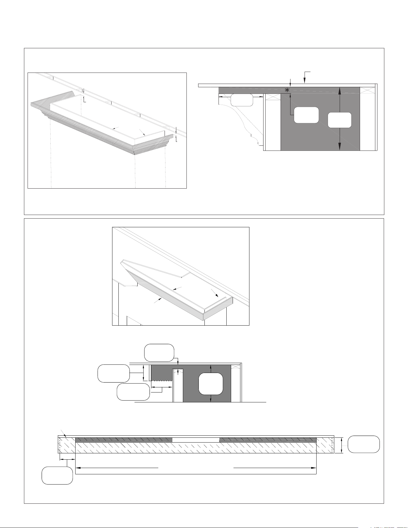
#BHM-44 R.1 August 2020 Hussong Mfg. Co., Inc. • Kozy Heat Fireplaces FRAMING 27
3.9.5 Top Vented Cavity Framing
NOTE: This vented cavity option allows the use of 19 gauge or less
hardware mesh that is 1/2” x 1/2” to prevent any items from entering
the vented cavity. This hardware mesh is optional and the only
approved item for use within the air discharge opening.
WARNING: Do NOT cover or place any items in the area of the air
discharge opening. Failure to comply with these instructions could
create a re hazard. Grilles and louvers are not allowed in the discharge
opening.
WARNING: Ensure air ow within the air discharge opening is not
restricted in any way.
WARNING: Enclosure measurements must maintain minimum
framing specs as outlined in Section 3.5 Rough Framing on page 15.
Minimum dimensions for the air discharge MUST BE maintained after
all nishing materials are installed.
These are minimum dimensions shown for the air discharge
opening, and the opening may be increased, if desired, as long as all
requirements are followed. It is recommended to limit your opening
for aesthetic purposes and to avoid items falling into the enclosure.
• Figure 3.21 shows the minimum 1-1/2” (38mm) clearance from
the replace enclosure top to the ceiling on all three sides of the
enclosure.
3.9.5.1 Top Vented Cavity Option
Alternative Installations
• Figure 3.22 on the following page shows the installation of
crown molding or similar trim work that goes up to the edge of
the air discharge opening. 12” (305mm) is the maximum length
of the molding or trim projection and you must maintain 1-1/2”
(38mm) clearance for the full length of crown molding/trim
projection. This molding or trim cannot decrease the minimum
opening requirement.
• Figure 3.23 on the following page shows an alternative
installation for the top vented cavity option with an air discharge
overhang in front of the air discharge opening. This installation
method can provide a means to visually hide the air discharge
opening.
Figure 3.21, Top Vented Cavity Installation
1½”
(38mm)
1
½”
(38mm)
1
½”
(38mm)
Top vented cavity option with air discharge opening on all three sides
Requires a minimum1½” (38mm) clearance from replace enclosure top to ceiling on all three sides
VENTED CAVITY INSTALLATIONS ONLY
28 FRAMING Hussong Mfg. Co., Inc. • Kozy Heat Fireplaces #BHM-44 R.1 August 2020
Figure 3.23, Top Vented Cavity Alternative Installation with Overhang
6”
(152mm)
8”
(203mm)
6”
(152mm)
8”
(203mm)
88”
(2235mm)
1
½”
(38mm)
Air discharge
overhang
Air discharge
opening entire
top at 1½”
Enclosure top
must be installed
Air discharge opening
Air discharge overhangAir discharge overhang
Width of replace chamber
D
MAX
MIN
MIN
MAX
MIN
88”
(2235mm)
MIN
Figure 3.22, Top Vented (all 3 sides) Cavity Crown Molding Installation
12”
(305mm)
88”
(2235mm)
1½”
(38mm)
MIN
MAX
MIN
Air discharge
opening
*must maintain 1-1/2” (38mm) clearance for
full length of crown molding/trim projection
Enclosure
Ceiling
SIDE VIEW
FRONT VIEW
1½”
(38mm)
1½”
(38mm)
Air discharge opening
entire top at
1-1/2” (38mm) minimum
VENTED CAVITY INSTALLATIONS ONLY
VENTED CAVITY INSTALLATIONS ONLY

#BHM-44 R.1 August 2020 Hussong Mfg. Co., Inc. • Kozy Heat Fireplaces FACING AND FINISHING 29
4.0 FACING AND FINISHING
4.1 Standard Installation Facing
and Finishing Requirements
WARNING: Maintain all minimum clearances to combustibles from the
appliance and vent system.
NOTE: See Section 4.10 Vented Cavity and KZK Facing and Finishing
Requirements on page 44 additional mantel, hearth, and sidewall
clearances.
4.1.1 Mantel and Hearth Requirements
WARNING: All minimum clearances to combustible material MUST be
maintained.
• Combustible Mantel Projections: As referenced in Figure 4.1,
the 3/4" trim can start at 16" (407mm) above the top nishing
edge with a 6" (152mm) mantel starting at 19-1/2" (496mm)
above the top nishing edge. Mantel projections can increase 1"
(25mm) of depth for every 1" (25mm) of height starting at the 6"
(152mm) mantel.
• Combustible Hearth: As referenced in Figure 4.1, the bottom
of the bottom nishing edge can be ush with the top of the
hearth.
• Non-combustible Mantel Projections: A minimum vertical
clearance of 6" (152mm) above the top nishing edge to a
maximum 6" (152mm) depth of a non-combustible mantel.
Follow projection 1" (25mm) up for every 1" (25mm) deeper. See
Figure 4.2 on page 31.
• Mantel Leg: Follow side combustible clearance below. See
Figure 4.3 on page 32.
• Side Combustible Clearance: 1” (25mm) combustible side
trim starts at 3” (76mm) from the side nishing edge. After 6”
(152mm), this projection is unlimited. See Figure 4.3 on page
32
4.1.2 Adjacent Sidewall Requirements
• The adjacent sidewall minimum clearance is 6" (152mm) from
the side nishing edges of the replace. See Figure 4.3 on page
32.
4.1.3 Facing Requirements
• Non-combustible material is required at the top and sides of
the replace. This replace is designed to accommodate non-
combustible facing material up to 1/2" (13mm) thick. See Figure
4.5 on page 34 for dimensions.
• Install facing material up to the nishing edge that surrounds
the glass frame assembly. Do not apply any material beyond this
point. The glass frame assembly must be removable.
• It is acceptable to pre-drill holes and to use self-tapping screws
prior to attaching the non-combustible material to the top
and sides of the replace face. Screws can only penetrate the
replace outer shell up to 1/2" (13mm) in the allowed areas.
4.1.4 Finishing Recommendations
NOTE: The surface area above the appliance may be aected by high
temperatures emitted from this appliance. To help avoid or reduce the
possibility of the sheetrock to crack, Hussong Mfg. Co., Inc. recommends
the following methods:
• Ensure the non-combustible material and sheetrock are dry and
dust free.
• For taping and mudding seams, we recommend heat
resilient tape, mesh and joint compounds, such as Durabond.
Joint compound must be cured as per manufacturer’s
recommendations.
• For a painted surface, use a high quality acrylic latex primer
and nish coat. Avoid at or light-colored paints to prevent
discoloring.
30 FACING AND FINISHING Hussong Mfg. Co., Inc. • Kozy Heat Fireplaces #BHM-44 R.1 August 2020
25½”
(648mm)
19
½”
(496mm)
16”
(407mm)
25”
(635mm)
27
½”
(699mm)
¾” (19mm)
Mantel Trim
88”
(2235mm)
22”
(558mm)
2
½”
(64mm)
16¼”
(412mm)
12” (305mm)
9” (229mm)
6” (152mm)
14” (356mm)
Top nishing edge
Bottom
nishing edge
Each square represents
1” of projection
Combustible Floor
Non-combustible zone
Non-combustible
material
Figure 4.1, Standard Installation Combustible Mantel and Hearth STANDARD INSTALLATION
#BHM-44 R.1 August 2020 Hussong Mfg. Co., Inc. • Kozy Heat Fireplaces FACING AND FINISHING 31
Figure 4.2, Standard Installation Non-combustible Mantel Clearances
STANDARD INSTALLATION
33½”
(851mm)
88”
(2235mm)
22”
(558mm)
6”
(152mm)
12” (305mm)
9” (229mm)
6” (152mm)
Top nishing
edge
Combustible Floor
Non-combustible zone
Non-combustible
material
Non-combustible
mantel ONLY
32 FACING AND FINISHING Hussong Mfg. Co., Inc. • Kozy Heat Fireplaces #BHM-44 R.1 August 2020
Figure 4.3, Standard Adjacent Sidewall Clearances
STANDARD INSTALLATION
88”
(2235mm)
3”
(76mm)
6”
(152mm)
1”
(25mm)
1”
(25mm)
6”
(152mm)
3”
(76mm)
Finishing Edge
unlimited
Top View
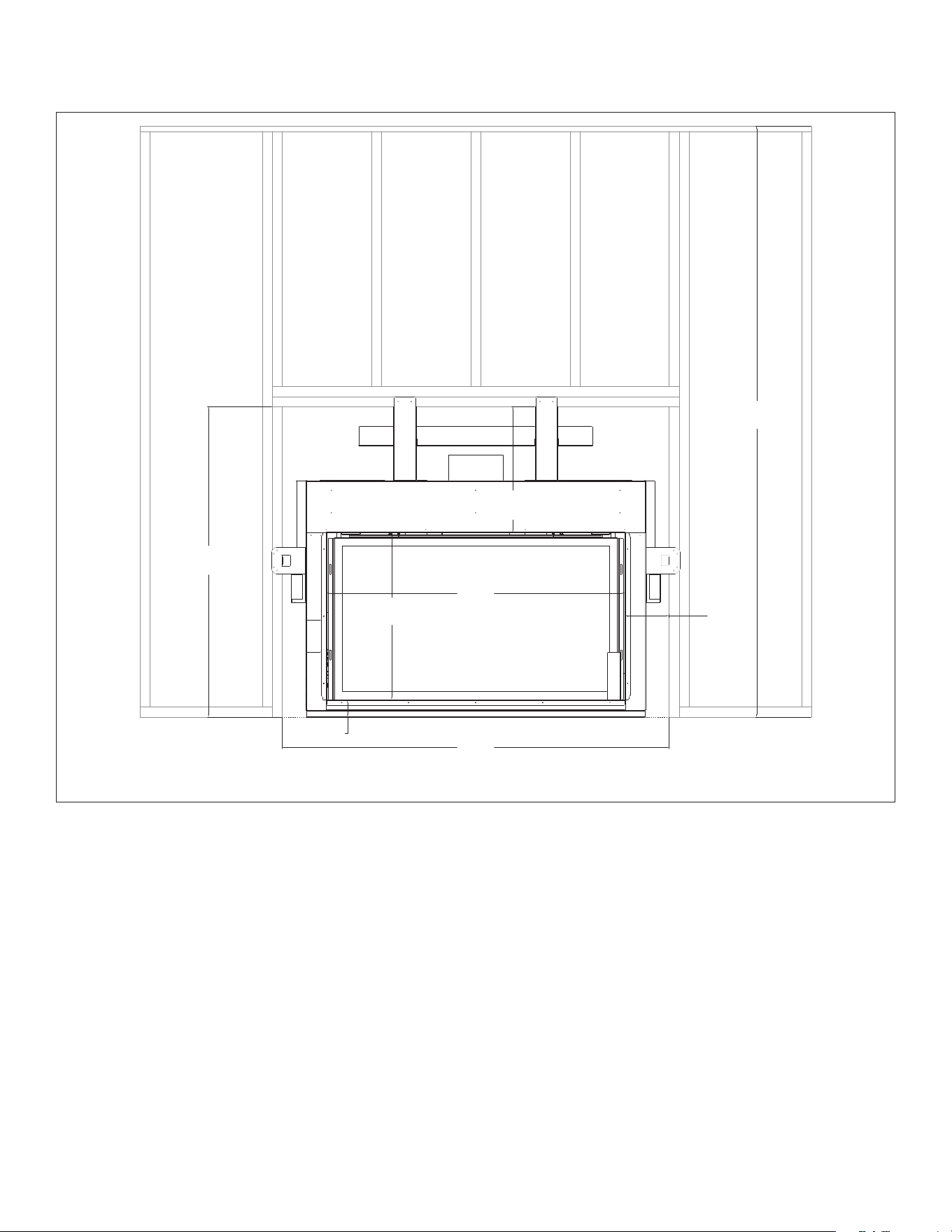
#BHM-44 R.1 August 2020 Hussong Mfg. Co., Inc. • Kozy Heat Fireplaces FACING AND FINISHING 33
Figure 4.4, Framed Opening Clearances
88”
(2235mm)
69⁄16”
(167mm)
57
5⁄8”
(1464mm)
2½”
(63mm)
247⁄8”
(632mm)
46¼”
(1175mm)
447⁄16”
(1129mm)
18¾”
(477mm)
ALL DESIGN OPTIONS INSTALLATION
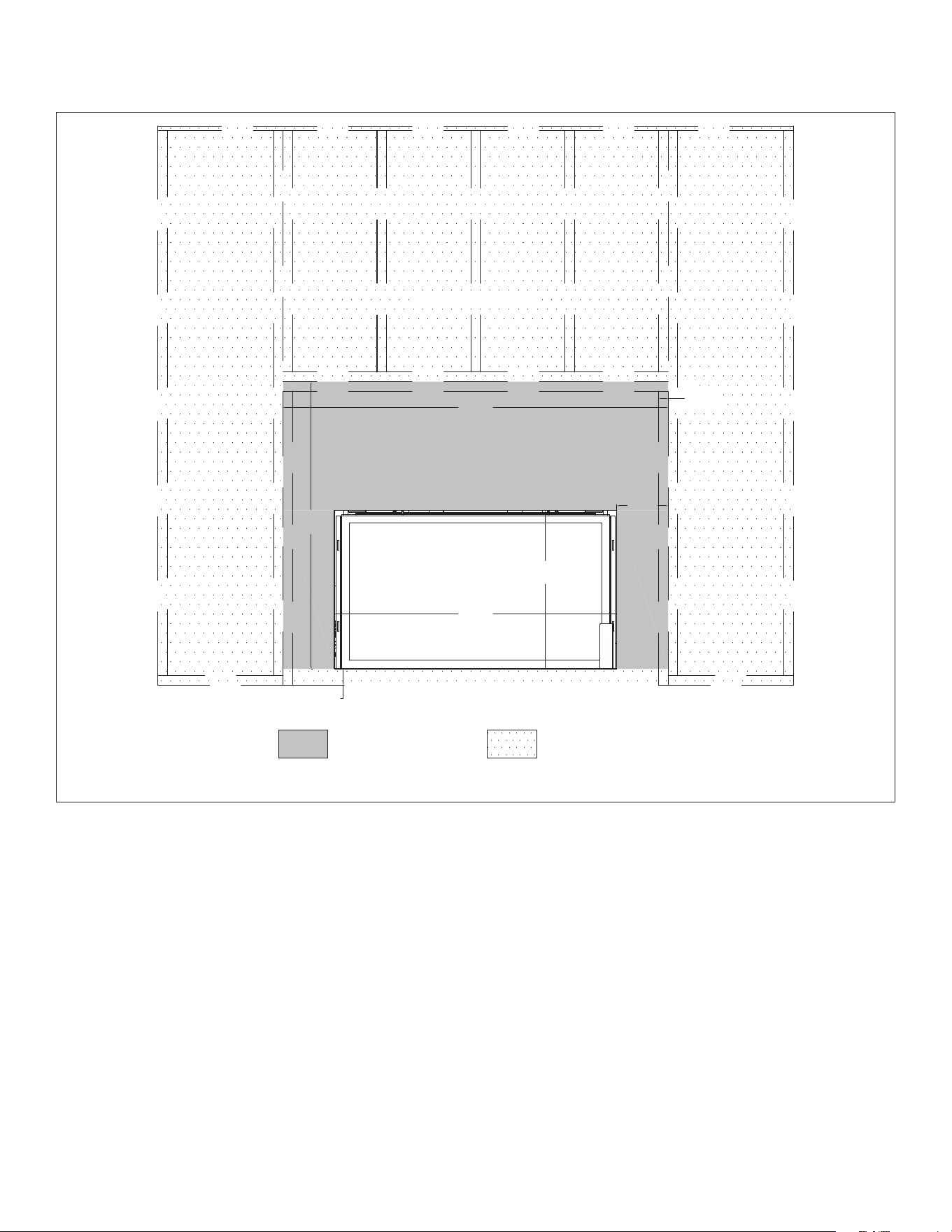
34 FACING AND FINISHING Hussong Mfg. Co., Inc. • Kozy Heat Fireplaces #BHM-44 R.1 August 2020
Figure 4.5, Minimum Finishing Dimensions
2½”
(63mm)
44½”
(1130mm)
2415⁄16”
(633mm)
1
½”
(38mm)
45
3⁄16”
(1148mm)
81⁄16”
(205mm)
605⁄8”
(1540mm)
Combustible material allowed
Non-combustible material only
Combustible material allowedNon-combustible material only
ALL DESIGN OPTIONS INSTALLATION
#BHM-44 R.1 August 2020 Hussong Mfg. Co., Inc. • Kozy Heat Fireplaces FACING AND FINISHING 35
4.2 Safety Barrier Installation
4.2.1 Safety Barrier Screen (#BH44-ES)
1. Locate the (4) slots ([2] on each side) located on each side of the
glass valance.
2. There are two mounting options based on notched tab position.
See below for a ush or a recessed mount.
3. Align the notched tabs, located on the back of the safety barrier
screen, with the slots on the glass valance for the desired mount.
4. Raise the safety barrier screen front slightly into slots and allow
the tabs to lower into position.
• To remove safety barrier screen: lift the screen up and out of
slots.
Figure 4.6, Safety Screen Installation
Recessed
mount
Flush
mount

36 FACING AND FINISHING Hussong Mfg. Co., Inc. • Kozy Heat Fireplaces #BHM-44 R.1 August 2020
4.3 Vented Cavity and KZK Facing
and Finishing Requirements
WARNING: Maintain all minimum clearances to combustibles from the
appliance and vent system.
WARNING! RISK OF FIRE : The following facing and nishing options are
for use ONLY when using an optional vented cavity or Komfort Zone Kit
with the convection bae and cover plates removed. DO NOT follow
these options unless you are using the vented cavity option.
4.3.1 Mantel and Hearth Requirements
WARNING: All minimum clearances to combustible material MUST be
maintained.
• Combustible Hearth and Mantel Projections - See Figure 4.7 on
page 37 for facing and nishing clearances.
• Mantel Leg: Follow side combustible clearance below. See
Figure 4.8 on page 38.
• Side Combustible clearance: 1” (25mm) combustible side trim
can be ush with the side nishing edge. After 6” (152mm), this
projection is unlimited. See Figure 4.8 on page 38.
4.3.2 Adjacent Sidewall Requirements
• The adjacent sidewall minimum clearance is 6" (152mm) from
the side nishing edges of the replace. See Figure 4.8 on page
38.
4.3.3 Facing Requirements
• Non-combustible material is required at the top and sides of
the replace. This replace is designed to accommodate non-
combustible facing material up to 1/2" (13mm) thick. See Figure
4.5 on page 34.
• Install facing material up to the nishing edge that surrounds
the glass frame assembly. Do not apply any material beyond this
point. The glass frame assembly must be removable.
• It is acceptable to pre-drill holes and to use self-tapping screws
prior to attach the non-combustible material to the top and sides
of the replace face, screws can only penetrate the replace
outer shell up to 1/2" (13mm) in the allowed areas. See Figure 4.5
on page 34.
4.3.4 Finishing Recommendations
NOTE: The surface area above the appliance may be aected by high
temperatures emitted from this appliance. To help avoid or reduce the
possibility of the sheetrock to crack, Hussong Mfg. Co., Inc. recommends
the following methods:
• Ensure the non-combustible material and sheetrock are dry and
dust free.
• For taping and mudding seams, we recommend heat
resilient tape, mesh and joint compounds, such as Durabond.
Joint compound must be cured as per manufacturer’s
recommendations.
• For a painted surface, use a high quality acrylic latex primer
and nish coat. Avoid at or light-colored paints to prevent
discoloring.
4.3.4.1 Combustible Wall Finish
• Figure 4.9 on page 39 shows installation of combustible wall
nish up to 1" (25mm) thick for Komfort Zone Kit(s) and Vented
Cavity installations. For KZK-1510A and KZK-045 installations,
reference the manuals included with the kit.
• Finishing materials cannot block the required vented cavity
discharge opening requirements.
• This combustible material goes on any required non-
combustible materials as shown in Figure 4.9 on page 39.
• This 1" (25mm) combustible material is able to go down to the
replace nishing edge and up to the air discharge opening.
#BHM-44 R.1 August 2020 Hussong Mfg. Co., Inc. • Kozy Heat Fireplaces FACING AND FINISHING 37
25”
(635mm)
27
½”
(699mm)
2
½”
(64mm)
12” (305mm)
9” (229mm)
6” (152mm)
14” (356mm)
Top nishing edge
Bottom
nishing edge
Each square represents
1” of projection
Combustible Floor
Combustible wall nish up to 1”
may be installed over cement
board and butt up to the nishing
edge around the opening
Non-combustible zone
Non-combustible
material
Figure 4.7, Vented Cavity & KZK Facing and Finishing Clearances
VENTED CAVITY AND KZK INSTALLATIONS ONLY
38 FACING AND FINISHING Hussong Mfg. Co., Inc. • Kozy Heat Fireplaces #BHM-44 R.1 August 2020
Figure 4.8, Vented Cavity and KZK Adjacent Sidewall Clearances
1”
(25mm)
6”
(152mm)
88”
(2235mm)
6”
(152mm)
1”
(25mm)
Finishing Edge
unlimited
Top View
VENTED CAVITY AND KZK INSTALLATIONS ONLY
#BHM-44 R.1 August 2020 Hussong Mfg. Co., Inc. • Kozy Heat Fireplaces FACING AND FINISHING 39
Figure 4.9, Combustible Wall Finish up to 1" (25mm) thick
88”
(2235mm)
22”
(558mm)
16
¼”
(412mm)
Air discharge opening
Combustible wall nish
up to 1” (25mm) thick
may be installed up to
the top nishing edge
and the bottom of the
air discharge opening
Top nishing edge
Bottom nishing edge
Non-combustible zone
Non-combustible
material
VENTED CAVITY AND KZK INSTALLATIONS ONLY
40 GAS LINE CONNECTION Hussong Mfg. Co., Inc. • Kozy Heat Fireplaces #BHM-44 R.1 August 2020
5.0 GAS LINE CONNECTION
5.1 Gas Conversion
The gas conversion kit is sold separately.
ATTENTION: The conversion shall be carried out in accordance with the
requirements of the provincial authorities having jurisdiction and in
accordance with the requirements of the ANSI Z223.1 installation code.
This replace is manufactured for use with natural gas. Follow the
instructions included with the conversion kit if converting to propane.
5.2 Gas Line Installation
CAUTION: Installation of the gas line must only be done by a qualied
person in accordance with local building codes, if any. If not, follow
ANSI Z223.1. Commonwealth of Massachusetts installations must be
done by a licensed plumber or gas tter.
NOTE: The appliance and its individual shuto valve must be
disconnected from the gas supply piping system during any pressure
testing of that system at pressures in excess of ½ psi (3.5 kPa). For test
pressures equal to or less than ½ psi (3.5 kPa), the appliance must be
isolated from the gas supply piping system by closing its individual
manual shut-o valve.
• A listed (and Commonwealth of Massachusetts approved)
½” (13mm) tee handle manual shut-o valve and exible gas
connector are to be connected to the ½” (13mm) control valve
inlet. If substituting for these components, please consult local
codes for compliance.
• This replace is equipped with a 3/8” (10mm) x 36” (914mm) long
exible gas connector and manual shut-o valve.
• Run gas line into replace into the access hole provided. Refer
to Figure 2.1, BHM-44 Dimensions on page 9. The gas line
should be run to the point of connection where the shut-o
valve and exible gas line will connect.
• Do not run gas line in a manner that would obstruct fan
operation.
• For high altitude installations, consult the local gas distributor or
the authority having jurisdiction for proper rating methods.
Table 5.1, Inlet Gas Supply Pressures
Fuel Minimum Pressure Maximum Pressure
Natural Gas 5” WC (1.25 kPa)
7” WC (1.74 kPa )
recommended
10.5” WC (2.62 kPa)
Propane 12” WC (2.99 kPa)
recommended
13” WC (3.24 kPa)
#BHM-44 R.1 August 2020 Hussong Mfg. Co., Inc. • Kozy Heat Fireplaces NATURAL DRAFT TERMINATION LOCATIONS 41
6.0 NATURAL DRAFT TERMINATION LOCATIONS
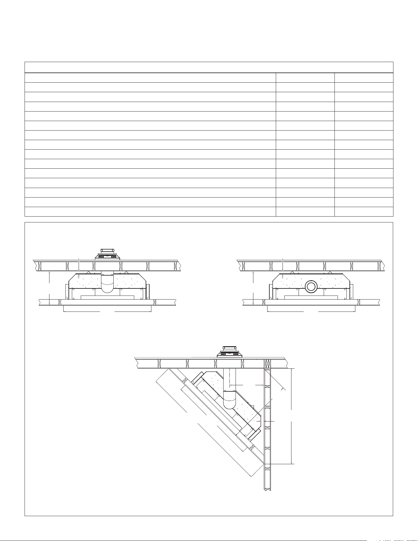
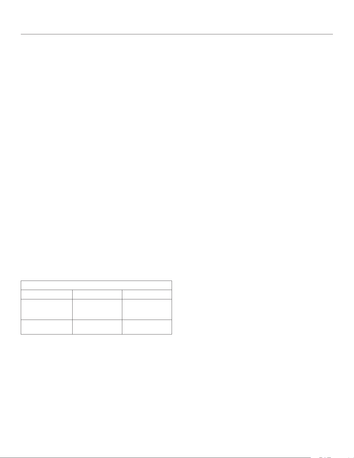
6.1 Vertical Natural Draft Vent Termination
WARNING: This appliance must not share or be connected to a chimney
ue serving a separate solid-fuel burning appliance.
Minimum height (H) from roof
Roof Pitch Feet Meters
Flat to 6/12 1.0 0.30
Over 6/12 to 7/12 1.25 0.38
Over 7/12 to 8/12 1.5 0.46
Over 8/12 to 9/12 2.0 0.61
Over 9/12 to 10/12 2.5 0.76
Over 10/12 to 11/12 3.25 0.99
Over 11/12 to 12/12 4.0 1.22
Over 12/12 to 14/12 5.0 1.52
Over 14/12 to 16/12 6.0 1.83
Over 16/12 to 18/12 7.0 2.13
Over 18/12 to 20/12 7.5 2.27
Over 20/12 to 21/12 8.0 2.44
12
x
HH
Lowest
discharge
opening
Approved cap
Approved
vent pipe
Roof pitch = x/12
H - Minimum height from roof to lowest
discharge opening
Minimum
12” (.30m)
Figure 6.1, Vertical Vent Cap Clearance
42 NATURAL DRAFT TERMINATION LOCATIONS Hussong Mfg. Co., Inc. • Kozy Heat Fireplaces #BHM-44 R.1 August 2020
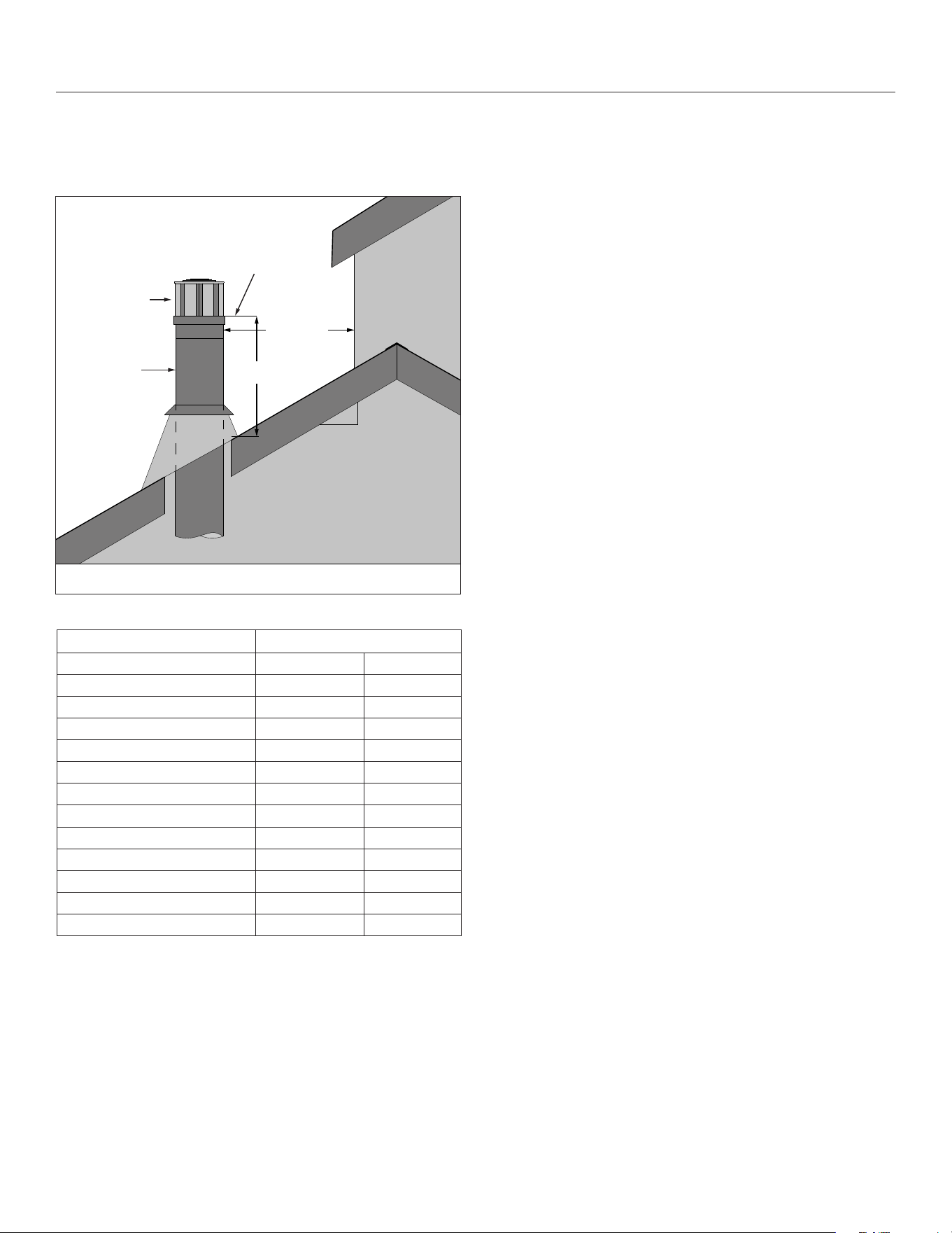
6.2 Minimum Natural Draft Vent Termination Clearances
AREA WHERE TERMINAL
IS NOT PERMITTED
B
B
L
J
K
C
G
P
H
I
D
E
A
N
F
M
O
Canadian installations US installations
A Clearance above grade, veranda, porch, deck, or balcony 12” (30cm) 12” (30cm)
B Clearance to window or door that may be opened 12” (30cm) 9” (23cm)
C Clearance to permanently closed window (recommended to prevent condensation on
window)
12” (30cm)* 12” (30cm)*
D Vertical clearance to ventilated sot located above the terminal within a horizontal
distance of 2 feet (61 cm) from the center line of the terminal
24” (61cm)* 24” (61cm)*
E Clearance to unventilated sot 12” (30cm)* 12” (30cm)*
F Clearance to outside corner 0” (0cm)* 0” (0cm)*
G Clearance to inside corner 12” (30cm)* 12” (30cm)
H Clearance to each side of center line extended above meter/regulator assembly 3’ (91cm) within a height
15’ (4.5m) above the meter/
regulator assembly
*
I Clearance to service regulator vent outlet 3’ (91cm) *
J Clearance to non mechanical air supply inlet to building or the combustion air inlet to
any other appliance
12” (30cm) 9” (23cm)
K Clearance to mechanical air supply inlet 6’ (1.83m) 3’ (91cm) above if within 10’
(3m) horizontally
Massachusetts: 10’ (3m)
L Clearance above paved sidewalk or paved driveway located on public property 7’ (2.13m)† *
M Clearance under veranda, porch deck, or balcony 12” (30cm)‡ 12” (30cm)
N Clearance between two horizontal terminations 12” (30cm) 12” (30cm)
O Clearance between two vertical terminations (may be same height) 12” (30cm) 12” (30cm)
P Above furnace exhaust or inlet 12” (30cm) 12” (30cm)
* Clearance in accordance with local installation codes and the requirements of the gas supplier.
† A vent shall not terminate directly above a sidewalk or paved driveway that is located between two single family dwellings and serves both dwellings.
‡ Permitted only if veranda, porch, deck, or balcony is fully open on a minimum of two sides beneath the oor.
VINYL SOFFIT, VINYL CEILING, AND VINYL OVERHANG DISCLAIMER: Clearances to heat resistant material (i.e. wood, metal). This does not include vinyl. Hussong
Manufacturing Co., Inc. will not be held responsible for heat damage caused from terminating under vinyl overhangs, vinyl ceilings, or vinyl ventilated/unventi-
lated sots.
Figure 6.2, Vent Cap Locations
#BHM-44 R.1 August 2020 Hussong Mfg. Co., Inc. • Kozy Heat Fireplaces VENTING 43
7.0 VENTING
7.1 Approved Vent Systems
This appliance is equipped for use with a 5” (127mm) exhaust by 8”
(203mm) air intake co-axial vent pipe system.
This appliance is approved for use for Kozy Heat Power Venting #KPV
(sold separately).
This appliance is approved for use with manufacturers (horizontal and
vertical terminations): American Metal Products (Ameri-Vent), BDM,
ICC, Metal Fab*, Olympia Chimney Supply, Inc., Selkirk, and Simpson
DuraVent. See Sections 7.1.1 and 7.1.2.
*WHEN INSTALLING METAL FAB VENT SYSTEM with this appliance an
adapter must be used. Use adapter part number 5DDA. See Section
3.6 Natural Draft Vent Termination Rough Framing on page 41 for
more information.
This appliance can be adapted to use 4” diameter aluminum exible
pipe when used in combination with an existing minimum 7” ID Class
A metal chimney. See Section 7.5 Class A Chimney/Masonry Chimney
Conversion on page 48.
The 5” x 8” and 4” x 6-5/8” vent congurations listed in this manual
are shown with rigid pipe. Flexible pipe may be used for approved
venting congurations by approved vent manufacturers (listed
below). Refer to the vent manufacturer’s installation instructions.
Refer to the vent manufacturer’s installation manual for complete
installation instructions. Vent installation must conform with venting
requirements and restrictions as outlined in this manual.
7.1.1 Approved 5” x 8” Vent Systems
Table 7.1, Approved 5” x 8” Vent Systems
Vent Manufacturer Vent Cap Part Number
American Metal Products
(Ameri-Vent)
5DHCS
5DHC
5DVC
BDM DVR8-HCP
DVR8-VCLP
DVR8-VCH
Simpson DuraVent 58DVA-HC
58DVA-VCH
58DVA-VC
58DVA-VCE
ICC TM-5HT
TM-5RHT
TM-5SVT
Metal Fab
(Adapter 5DDA must be used)
5DHT
5DVT
5DVTHW
Olympia Chimney Supply, Inc. VDV-HC05
VDV-VC05
VDV-VCH05
Selkirk 5DT-HC
5DT-HCR
5DT-VT
5DT-VC
7.1.2 Approved 4” x 6-5/8” Vent Systems
This appliance may be reduced from a 5” x 8” to a 4” x 6-5/8” vent
system using a vent reducer from an approved vent system. Refer
to the vent pipe manufacturer’s installation manual for more
information.
Table 7.2, Approved 4” x 6-5/8” Vent Systems
Vent Manufacturer Vent Cap Part Number
American Metal Products
(Ameri-Vent)
4DHCS
4DHC
4DVC
BDM DVR6-HCP
DVR6-VCLP
DVR6-VCH
Simpson DuraVent 46DVA-HC
46DVA-VCH
46DVA-VC
46DVA-VCE
ICC TM-4HT
TM-4RHT
TM-4SVT
Kozy Heat KPV
Metal Fab 4DHT
4DVT
4DVTHW
Olympia Chimney Supply, Inc. VDV-HC04
VDV-VC04
VDV-VCH04
Selkirk 4DT-HC
4DT-HCR
4DT-VT
4DT-VC
7.2 Venting Requirements
NOTE: Consult the local and national installation codes to assure
adequate combustion and ventilation air is available. Venting
requirements apply to both natural gas and propane.
• Flame height and appearance will vary depending upon venting
conguration and the type of fuel used.
• Provide a means for visually checking the vent connection to the
appliance after the replace is installed.
• A minimum of 1” (25mm) clearance on all sides of the vertical
vent pipe must be maintained. Attic insulation shields may
be insulated using unfaced insulation products listed as
noncombustible per ASTM E 136.
• A minimum of 1” (25mm) clearance on the top, sides, and
bottom of the horizontal vent pipe must be maintained.
Wall thimble products that comply with the required clearances
to combustibles must be installed for all horizontal vent runs
that pass through interior or exterior walls. These wall thimble
products may be insulated using unfaced insulation products
listed as noncombustible per ASTM E 136.
44 VENTING Hussong Mfg. Co., Inc. • Kozy Heat Fireplaces #BHM-44 R.1 August 2020
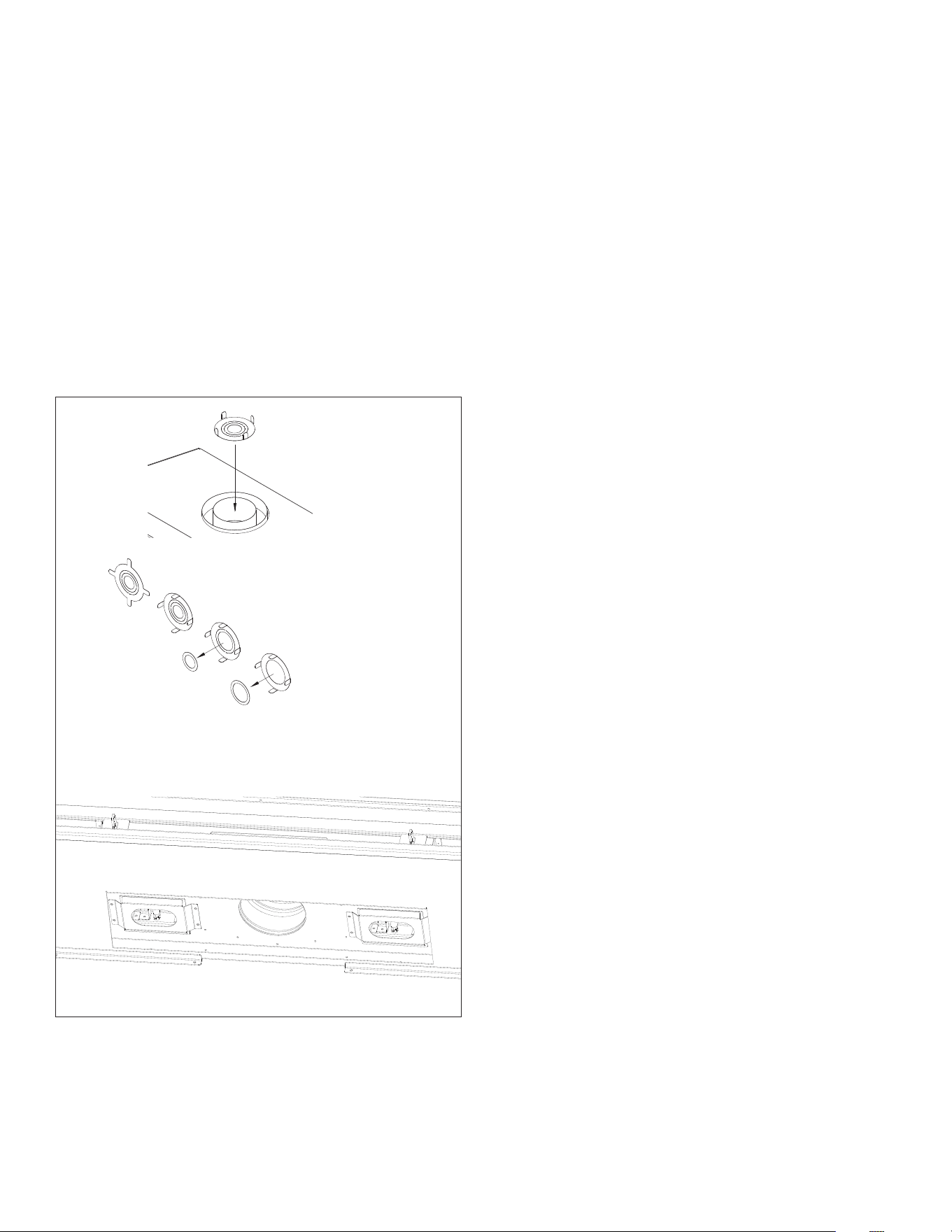
7.3 Natural Draft Vent Restriction
Burner ame appearance and characteristics are aected by altitude,
fuel quality, venting conguration, and other factors. To achieve
desirable ame appearance, the vent exhaust may be restricted by
the restrictor plate (included in components packet).
The restrictor plate is shipped with all inner rings intact, and when
installed, provides the most vent restriction. There are (2) inner rings
that can be knocked out. The innermost ring knocked out will create
less restriction, and the outer most ring knocked out will create the
least amount of restriction.
Follow Figure 7.1 for restrictor plate installation before attaching
venting or through the bae if venting is already attached. For vent
restriction plate recommendations and adjustments, see Section
11.2.2 Vent Restriction (after installation) on page 67.
Restrictor Plate
Slide restrictor into exhaust pipe on
top of replace with the tabs facing
towards you prior to attaching venting
Bend tabs to approx. 80° angles to create
tension to hold itself in place when installed
Remove innermost circle
to create less restriction
Remove all inner rings for
the least restriction
Figure 7.1, Restrictor Plate Installation
Insert restrictor plate into 5” (127mm) exhaust pipe in rebox ceiling
with tabs facing towards you
#BHM-44 R.1 August 2020 Hussong Mfg. Co., Inc. • Kozy Heat Fireplaces VENTING 45
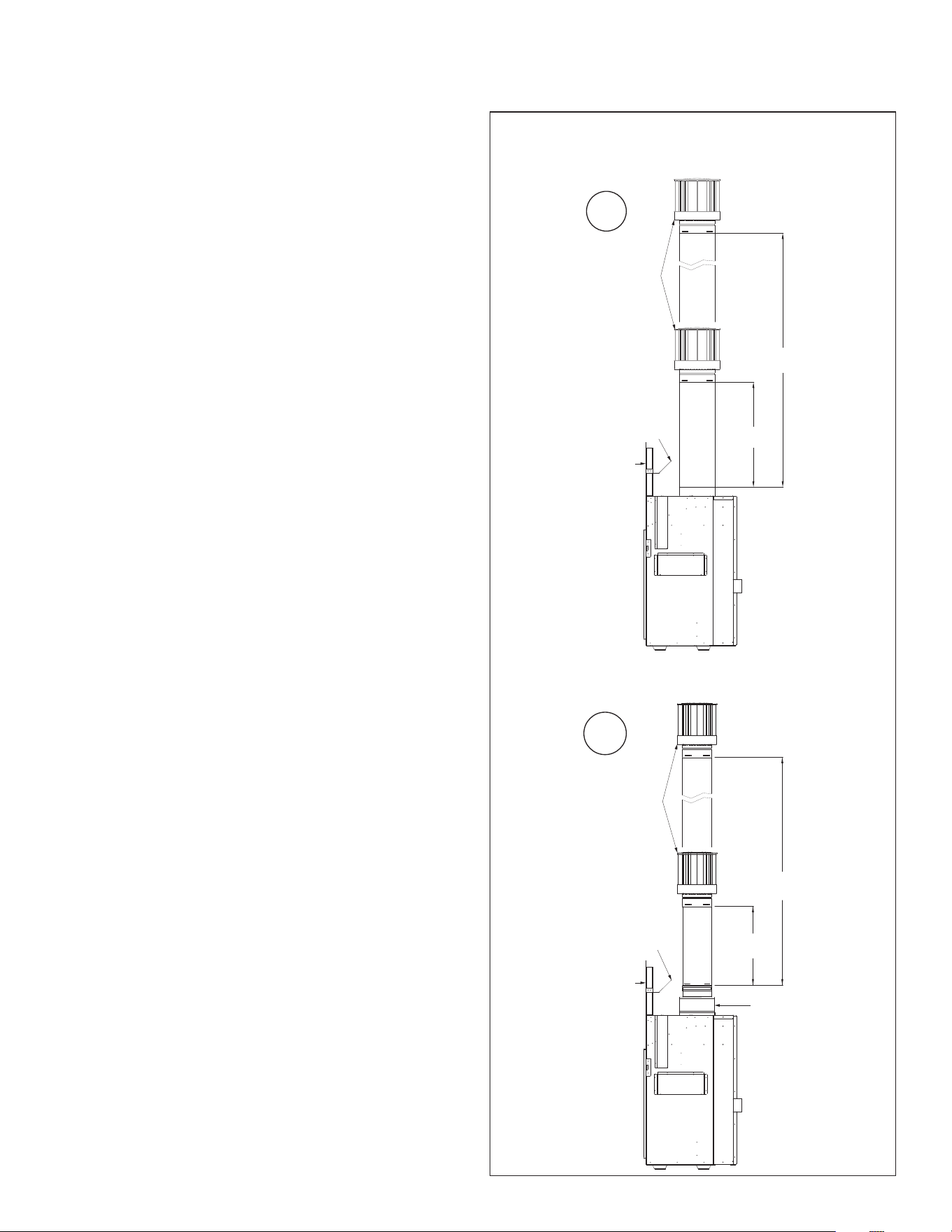
DIAG.1 NATURAL GAS & PROPANE VERTICAL TERMINATIONS
(A) Header Heat Shield
(B) Stand-o Assembly
(C) Reducer
(D) Termination Cap
7.4 Natural Draft Installation
7.4.1 Natural Gas and Propane
Vertical Terminations
Flexible pipe may be used for approved venting congurations by vent
manufacturers listed in Section 7.1 Approved Vent Systems on page
43.
(i) Minimum / Maximum Vertical Terminations:
3’ (914mm) minimum vertical length / 50’ (15.24m) maximum
vertical length + termination cap
(ii) Minimum / Maximum Vertical Terminations with Reducer*:
4” x 6-5/8” reducer + 3’ (914mm) minimum vertical length / 50’
(15.24m) maximum vertical length + termination cap
*To use any 45° elbow for vertical terminations with a reducer,
the total minimum vertical vent run must be 10’ (3.05m). A total
of (4) 45° elbows may be used. No 90° elbows are allowed. For
every 45° elbow used, 18” (457mm) must be subtracted from
maximum venting allowed.
50’
(15.24m)
36”
(914mm)
50’
(15.24m)
36”
(914mm)
A
B
D
A
B
C
D
i
ii
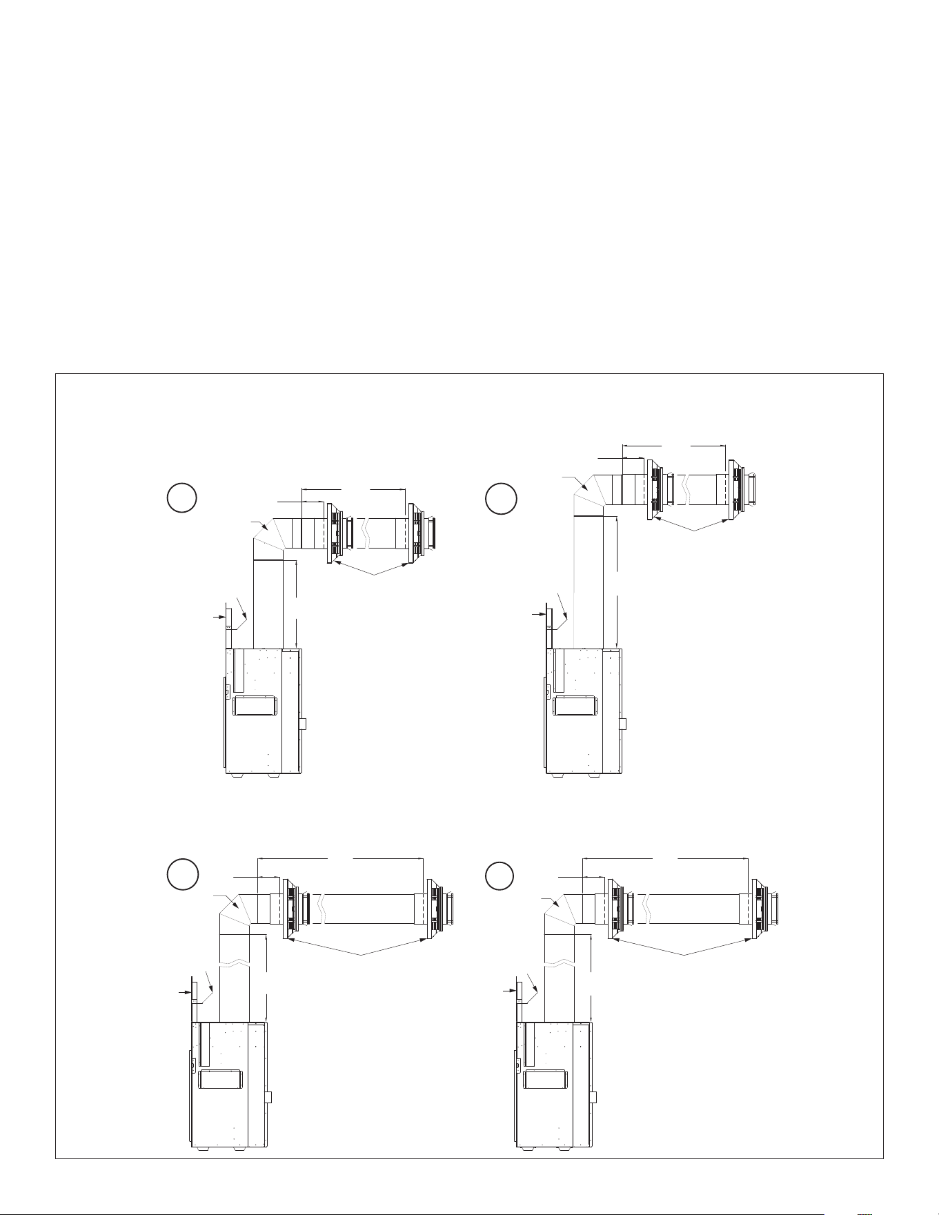
46 VENTING Hussong Mfg. Co., Inc. • Kozy Heat Fireplaces #BHM-44 R.1 August 2020
7.4.2 Natural Gas and Propane
Combination Venting
IMPORTANT: Horizontal vent sections require ¼” (6mm) rise for every
12” (305mm) of travel.
The vent congurations listed below are shown with rigid pipe.
Flexible pipe may be used for approved venting congurations by vent
manufacturers listed in Section 7.1 Approved Vent Systems on page
43.
(i) Minimum 24” Vertical Vent Pipe / Minimum / Maximum
Horizontal Termination
24” (610mm) vertical vent pipe + 90° horizontal elbow +
6” (152mm) minimum horizontal / 24” (610mm) maximum
horizontal + termination cap
(ii) Minimum 36” Vertical Vent Pipe / Minimum / Maximum
Horizontal Termination
36” (914mm) vertical vent pipe + 90° horizontal elbow + 6”
(152mm) minimum horizontal / 8’ (2.44m) maximum horizontal +
termination cap
(iii) Minimum 48” Vertical / Minimum / Maximum Horizontal
Termination
48” (1219mm) vertical vent length + 90° horizontal elbow + 6”
(152mm) minimum horizontal / 12’ (3.66m) maximum horizontal
+ termination cap
(iv) Maximum Vertical Venting / Minimum / Maximum Horizontal
Termination
25’ (7.62m) vertical vent length + 90° horizontal elbow + 6”
(152mm) minimum horizontal / 25’ (7.62m) maximum horizontal
+ termination cap
DIAG.2 NATURAL GAS & PROPANE COMBINATION VENTING
(A) Header Heat Shield
(B) Stand-o Assembly
(C) 90° Elbow
(D) Termination Cap
6”
(152mm)
24”
(610mm)
36”
(914mm)
8’
(2.44m)
25’
(7.62m)
12’
(3.66m)
48”
(1219mm)
6”
(152mm)
24”
(610mm)
6”
(152mm)
25’
(7.62m)
6”
(152mm)
A
B
C
D
A
B
C
D
C
A
B
D
C
A
B
D
i
ii
iv
iii
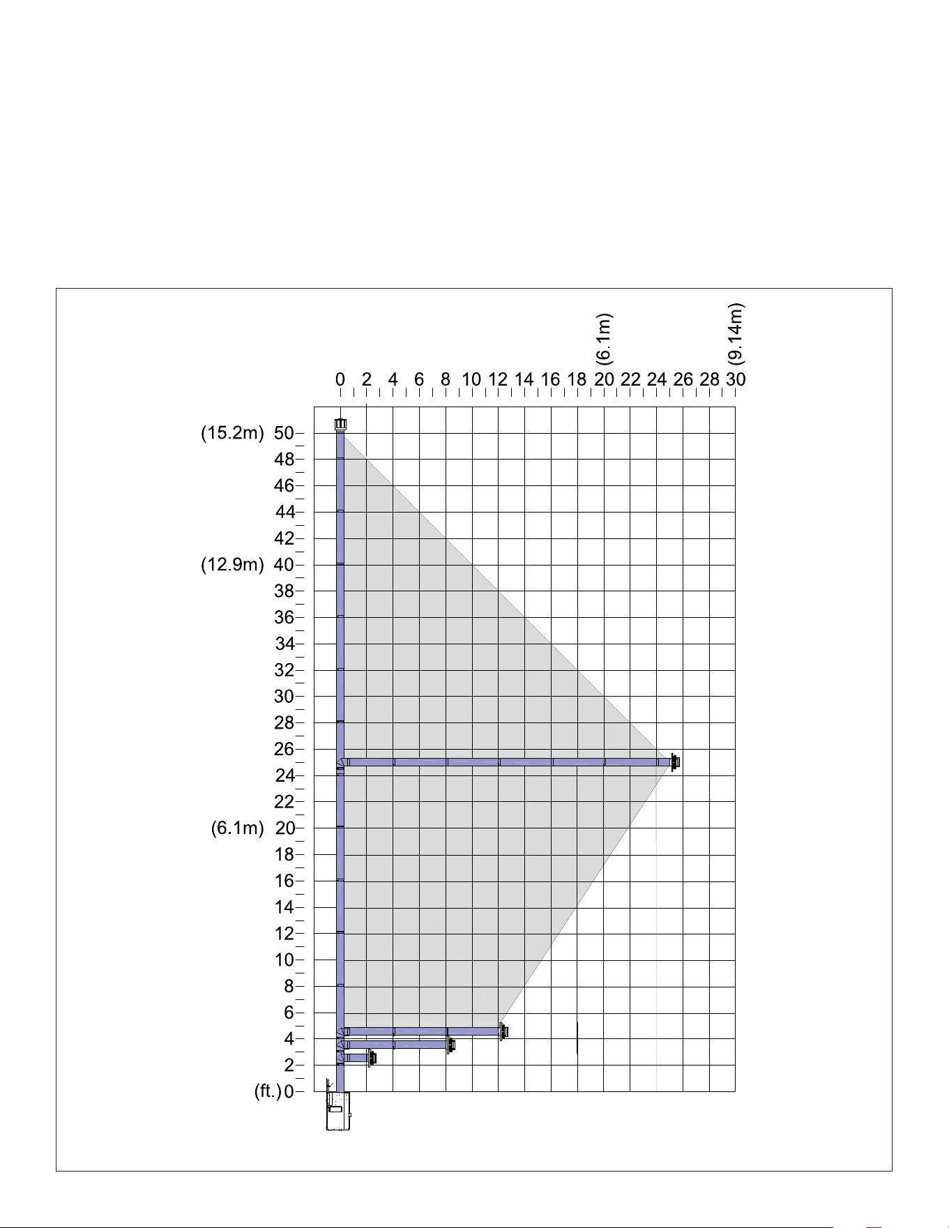
#BHM-44 R.1 August 2020 Hussong Mfg. Co., Inc. • Kozy Heat Fireplaces VENTING 47
Figure 7.2, Natural Gas and Propane Natural Draft Combination Venting
7.4.3 Natural Gas and Propane Maximum
Vertical & Maximum Horizontal
Combination Venting
For maximum vertical and maximum horizontal combination venting,
the vent terminations must be within the shaded area in Figure 7.2.
Flexible pipe may be used for approved venting congurations by vent
manufacturers listed in Section 7.1 Approved Vent Systems on page
43.
• 25’ (7.6m) maximum vertical rise + 25’ (7.6m) maximum
horizontal run = 50’ (15.2m) of total length
• Maximum of (5) 90° elbows.
• For each additional 90° elbow used after the rst elbow, 3’
(914mm) must be subtracted from maximum venting allowed.
• For each 45° elbow used, 18” (457mm) must be subtracted from
maximum venting allowed.
• (2) 45° degree elbows may be used in place of (1) 90° elbow.
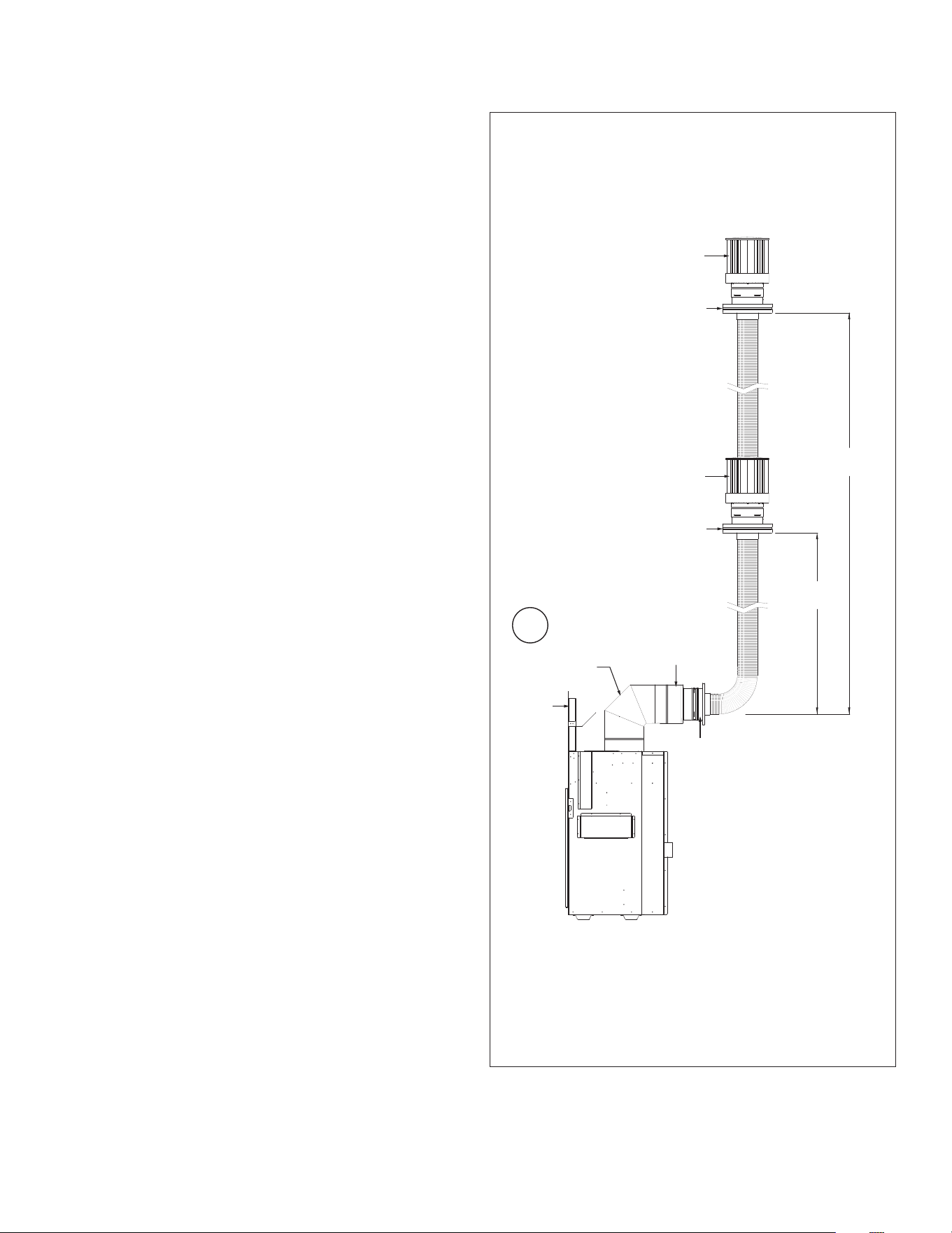
48 VENTING Hussong Mfg. Co., Inc. • Kozy Heat Fireplaces #BHM-44 R.1 August 2020
7.5 Class A Chimney/Masonry
Chimney Conversion
This appliance is approved to be adapted for Class A/Masonry
Chimney conversion with kits utilizing a 4” (102mm) exible exhaust
by any vent manufacturers listed in Section 7.1 Approved Vent
Systems on page 43.
Before conversion, have the existing installation inspected by a
qualied chimney sweep or professional installer. The existing
chimney system must be in serviceable condition, and functionally
sound. Before proceeding with following installations, check with
local building jurisdiction to verify this type of installation is allowed
in your area.
Follow DIAG. 3 for allowable venting congurations for installation
in existing through-the-ceiling, Class A/Masonry chimney. Route the
exhaust gases and intake air through the existing Class A/Masonry
chimney.
7.5.1 4” Flex Pipe Venting Congurations
IMPORTANT: Horizontal vent sections require at least 1/4” (6mm) rise
for every 12” (305mm) of travel.
IMPORTANT: The vent heat shield assembly must be installed when
incorporating minimum horizontal venting o the top of the appliance.
IMPORTANT: Care should be taken when installing exible pipe to avoid
a tight bend that may cause abrasion or damage to the exible pipe.
The vent option listed below allow for a minimum of 0” (0mm) to a
maximum of 24” (610mm) horizontal run using rigid or exible pipe.
(i) Minimum / Maximum Vertical Terminations:
90° horizontal elbow + reducer + retro connector + 10’ (3.05m)
minimum length of 4” aluminum flexible pipe / 50’ (15.24m)
maximum length of 4” aluminum flexible pipe + top adapter +
termination cap
DIAG.3 4” FLEX PIPE CHIMNEY CONVERSION
(A) Stand-o Heat Shields
(B) 90° Elbow
(C) Reducer
(D) Retro Connector
(E) Top Adapter
(F) Termination Cap
10’
(3.05m)
50’
(15.24m)
A
D
B
E
F
E
F
C
i
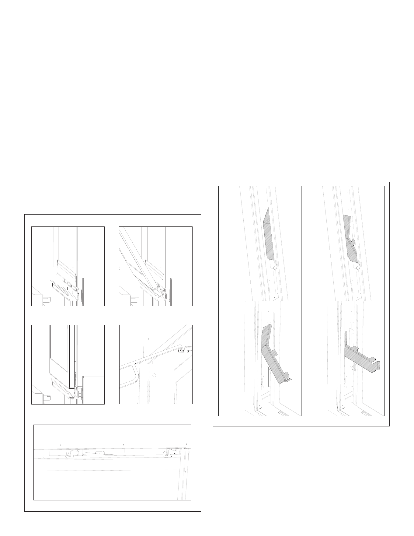
#BHM-44 R.1 August 2020 Hussong Mfg. Co., Inc. • Kozy Heat Fireplaces FIREPLACE SETUP 49
8.0 FIREPLACE SETUP
8.1 Glass Frame Assembly
WARNING: Do not operate this replace with the glass removed,
cracked, or broken. Replacement of the glass assembly should be done
by a licensed or qualied service person.
8.1.1 Remove Glass Frame Assembly
WARNING: Do not remove the glass assembly when hot.
1. Remove the safety barrier screen.
2. Locate (2) spring-loaded latches securing the glass assembly at
the top of the rebox. Use the provided tool to unlatch the latch
assemblies from the ange on top of the glass valance.
3. Tilt the top of the glass valance forward and lift up to remove the
valance resting on the bottom frame rail.
8.1.2 Install Glass Frame Assembly
1. Tilt the top of the glass valance forward and align the glass
valance with the bottom frame rail
2. Use the provided tool to pull the (2) latch assemblies to latch
with the ange on top of the glass valance.
3. Reinstall safety barrier screen.
BOTTOM FRAME RAIL GLASS VALANCE ON FRAME RAIL
VALANCE AGAINST UNIT
PROVIDED LATCH TOOL ATTACHED
TO TOP LATCH ASSEMBLY
TWO LATCHES SECURING VALANCE
Figure 8.1, Glass Frame Assembly Removal
8.2 Gas Valve Access Cover Plate
Removal and Installation
To access the gas valve, you will need to remove the access cover
plate. The cover plate is attached by magnets. To remove,
1. Remove the safety barrier screen and glass frame assembly.
2. Take the top of the access cover plate and pull it back (towards
you).
3. Lift up the access cover plate and pivot out, as shown below.
4. Remove access cover plate from replace.
5. To reinstall, follow the drawing below. Align the tabs on the
cover plate with the slots in the opening.
6. When nished, reinstall the gas valve access cover plate, glass
frame assembly, and safety barrier screen.
Figure 8.2, Gas Valve Access Cover Plate
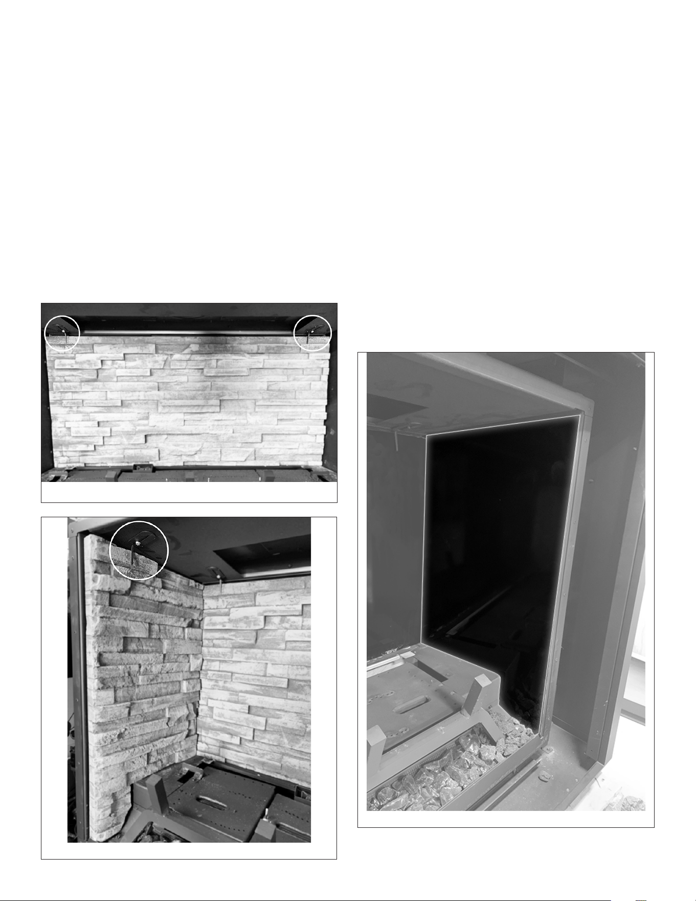
50 FIREPLACE SETUP Hussong Mfg. Co., Inc. • Kozy Heat Fireplaces #BHM-44 R.1 August 2020
8.3 Panel Installation
WARNING: RISK OF FIRE! Do not operate this replace without a
refractory or black glass panel kit installed.
• Refractory or black glass panels will provide insulation and are
required to operate this replace.
• If converting to propane, complete the conversion before
installing any refractory or black glass panels. Follow instructions
included with the kit.
BEFORE INSTALLATION:
1. Remove the safety barrier screen, glass assembly, and log set (if
installed).
2. Locate the (2) screw holes in the rear of the replace bae and
the (2) screw holes located on each side of the replace bae.
Locate the (4) panel clips shipped with the panels. These clips are
shipped at. Separate the clips at the perforations and bend the
metal nger at a 90° angle.
Figure 8.3, Back Refractory Panel Installed
Figure 8.4, Side Refractory Panel Installed
Figure 8.5, Side Black Glass Panels Installed
8.3.1 Refractory Panels
1. Install back refractory panel. Secure with panel clips previously
bent. See Figure 8.3.
2. Install side refractory panels. Tilt the back of the panel in rst
then pivot up. Secure with (2) panel clips for each side with
provided screws. See Figure 8.4.
8.3.2 Black Glass Panels
NOTE: The smooth side of the glass panel will face forward in the
rebox, with the textured side against the rebox walls.
It is recommended to wear clean gloves when handling panels. Handle
with care. Use both hands when installing.
1. Install back black glass panel. Secure with panel clips previously
bent with provided screws. Verify black glass is at against the
rebox.
2. Install side black glass panels. Carefully slide the panel on the
main log support until you reach the back of rebox as shown in
Figure 8.5.
3. Secure side panels with refractory clips previously bent. Verify
black glass is at against rebox.
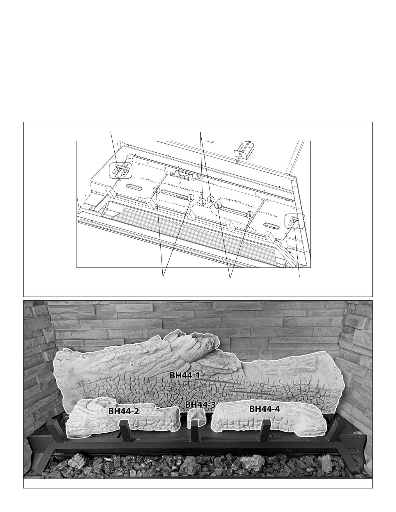
#BHM-44 R.1 August 2020 Hussong Mfg. Co., Inc. • Kozy Heat Fireplaces FIREPLACE SETUP 51
8.4 #BH44-500 Log Set Installation
CAUTION: Do not place logs directly over burner portholes. Improper
log placement may aect ame appearance and cause excessive soot
to build upon the logs and glass.
Refractory panels or black glass panels must be installed. The following
pictures are shown without panels for clarity purposes only.
• If converting to propane, complete the conversion before
installing the log set. Follow the conversion instructions included
with the kit.
• Log numbers are located on the bottom of each log. Refer to the
following instructions and illustrations for proper log placement.
1. Using both hands, place log BH44-1 at the rear of the rebox, as
shown in Figure 8.7. Slide the log forward until it rests against
the log stop bracket anges (Figure 8.6).
2. Align the holes in the bottom of logs BH44-2, BH44-3, and
BH44-4 with the corresponding studs located on the burners.
See Figure 8.6 for burner stud locations.
Instructions continue on the following page.
Log stop bracket Studs for log BH44-3
Studs for log BH44-2 Studs for log BH44-4 Log stop bracket
Figure 8.6, Burner Stud Locations and Log Stop Brackets
Figure 8.7, Base Logs
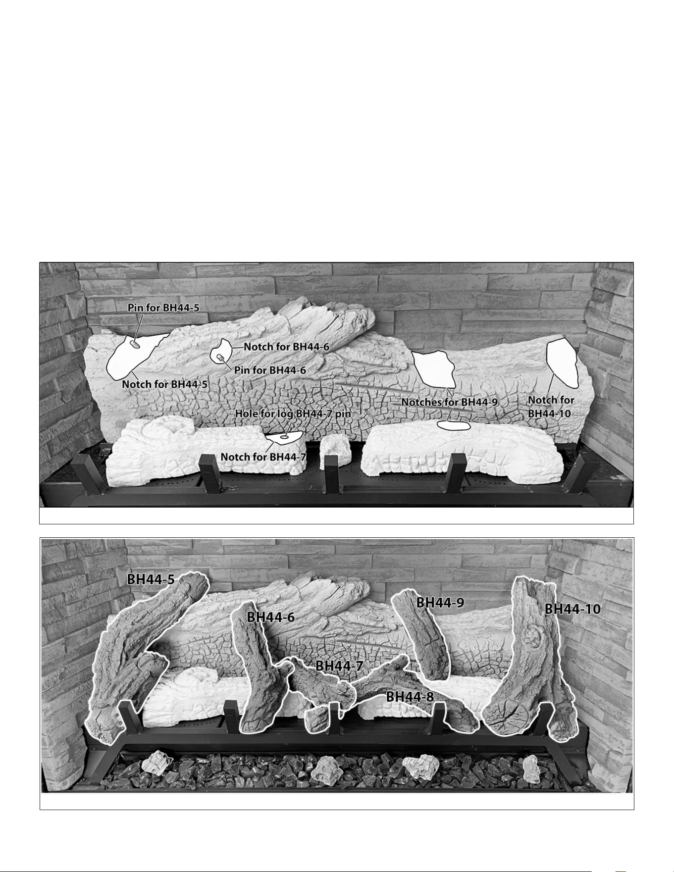
52 FIREPLACE SETUP Hussong Mfg. Co., Inc. • Kozy Heat Fireplaces #BHM-44 R.1 August 2020
Figure 8.8, Base Log Notches
Use Figures 8.8 and 8.9 together for the following instructions for
proper log placement.
3. Align the hole in the bottom of log BH44-5 with the pin on the
left hand side of log BH44-1 and set into position, as shown in
Figure 8.9.
4. Align the hole in the bottom of log BH44-6 with the pin in BH44-1
(Figure 8.8). Place as shown in Figure 8.9.
5. Place log BH44-8 on log BH44-4, as shown in Figure 8.9.
6. Align the pin in the bottom of log BH44-7 with the hole in the
notch in log BH44-2 (Figure 8.8), and set on to log BH44-8, as
shown in Figure 8.9.
7. Align log BH44-9 with the notches on log BH44-1 (Figure 8.8) and
log BH44-4, as shown in Figure 8.9.
8. Align log BH44-10 with the notch on log BH44-1 (Figure 8.8), and
place on log BH44-4, as shown in Figure 8.9.
9. Place crushed glass media into the ember bed media tray.
10. Place the (4) charred pieces on top of the ember bed. We show
one way to place the pieces, and you may place the pieces at
your discretion.
11. Distribute lava rock at the sides on the log support brackets and
rebox oor.
12. Use a steel or sti bristle nylon brush to distribute rock wool
embers onto logs and burners.
Figure 8.9, Completed Install
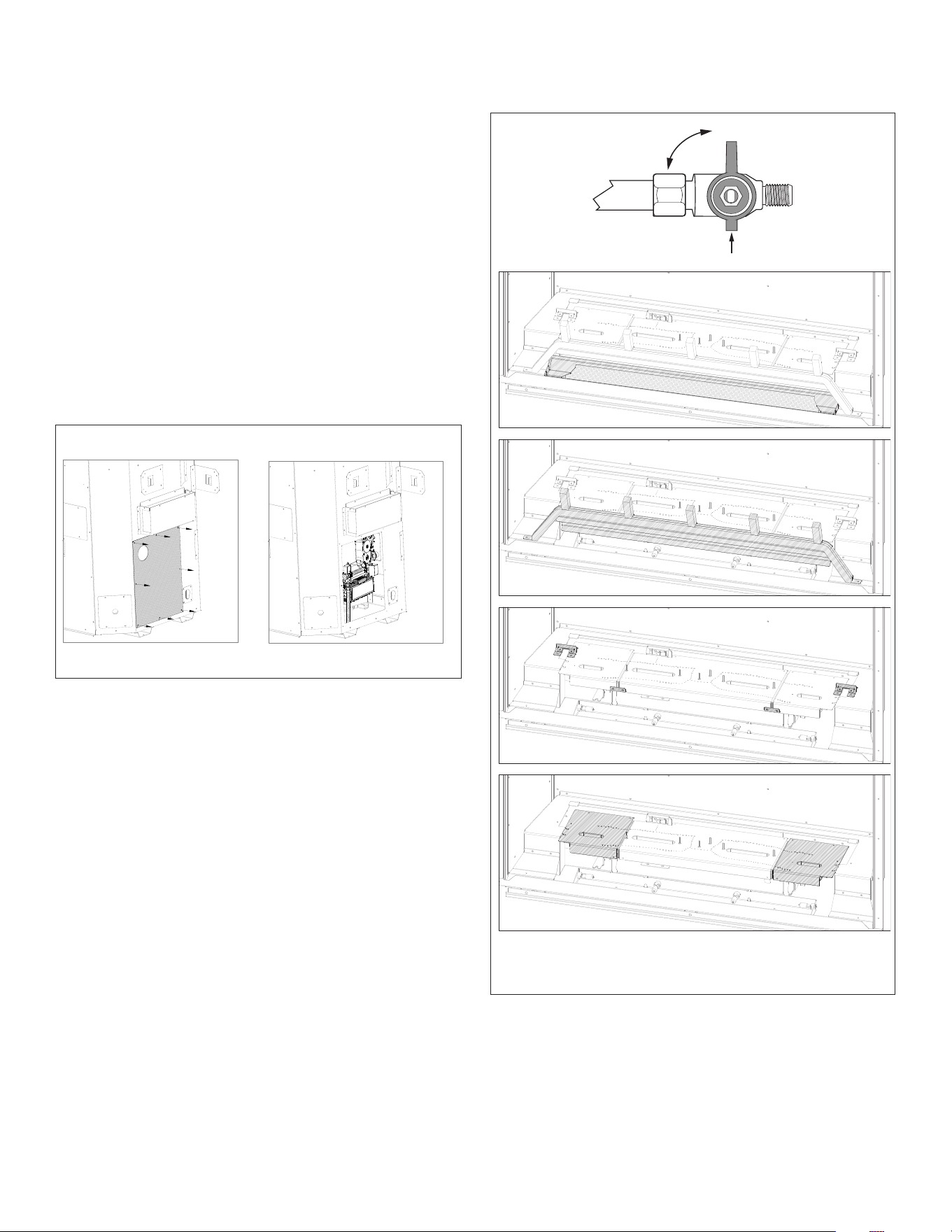
#BHM-44 R.1 August 2020 Hussong Mfg. Co., Inc. • Kozy Heat Fireplaces FIREPLACE SETUP 53
8.5 Control Board Access,
Removal and Installation
WARNING: Avoid burns or personal property damage by using
appropriate protection to remove any components if the burner and/
or pilot have been burning.
WARNING: DO NOT operate this appliance without the sealing gasket
in place. If the sealing gasket is damaged, it must be replaced.
CAUTION: Check all connections for leaks with soapy water, whether
eld or factory made.
8.5.1 Control Board Access Cover
On the left side of the unit, there is a control board access cover that
allows access to the control board without removing components
from the rebox.
For access, remove (8) screws securing cover to the outer shell.
Reinstall when nished.
8.5.2 Control Board Removal
1. Disconnect electrical power.
2. Locate the manual valve upstream of the appliance connector
and close valve.
3. Remove the safety barrier screen and glass frame assembly.
4. Remove log set and lava rock.
5. Remove refractory panel set or black glass panel set. Loosen
screws securing the (4) panel clips on the front sides and the
back of the replace bae. Remove panels from rebox.
6. Remove media tray.
7. Remove the log rack (1) screw on each side.
8. Remove the (2) log stop brackets (2) screws each side.
9. Remove the burner link brackets (4) screws.
10. Remove the side burners secured by (2) screws for each of the
side burners. Release the burner tube venturis o of the burner
orices and remove from rebox.
Instructions continue on the next page.
ON
OFF
Figure 8.10, Control Board Access Cover
Figure 8.11, Control Board Removal and Installation - 1
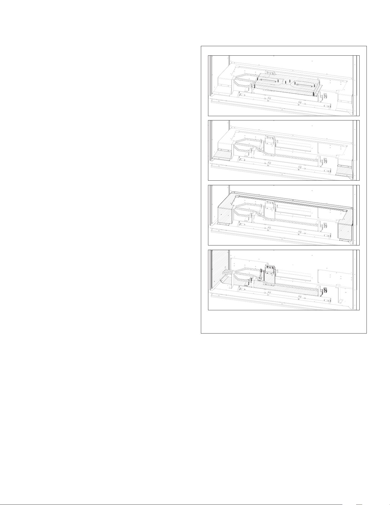
54 FIREPLACE SETUP Hussong Mfg. Co., Inc. • Kozy Heat Fireplaces #BHM-44 R.1 August 2020
11. Remove the center burner (4) screws total. Release the burner
tube venturi o of the burner orice by sliding the burner to the
right and remove from rebox.
12. Remove the left and right log support brackets, (2) screws each.
13. Remove the main log support. There are (2) screws on the left
and right side, and (3) screws on the rebox back wall.
14. It is recommended to remove (2) of the burner support brackets
on the left side of the rebox for easier control board removal.
There are (2) screws securing each of the brackets to the rebox
oor.
15. Remove and save (10) screws securing the control board.
16. Pull out control board out to reveal the gas line to disconnect
the gas line ex tube from replace valve, being careful not to
damage the sealing gasket.
8.5.3 Control Board Installation
Use Figure 8.11 and Figure 8.12 for guidelines to reinstall control board.
1. Place control board on the left side of the rebox and reconnect
gas line to replace valve. VERIFY SEALING GASKET IS IN
PLACE.
2. Secure the control board with screws previously removed.
3. Reinstall burner support brackets (if removed).
4. Reinstall the main log support. Align the holes in the main log
support with the holes in the rebox back wall and in left and
right sides of the rebox. Secure with screws previously removed.
5. Reinstall the left and right log support brackets. Secure with (4)
screws previously removed.
6. Reinstall center burner. Position the burner tube venturi over
the center burner orice and secure with (4) screws previously
removed.
7. Reinstall side burners. Position the burner tube venturis over the
corresponding left and right burner orices and secure with (4)
screws previously removed.
8. Reinstall burner link brackets.
9. Reinstall log stop brackets with (4) screws previously removed.
10. Reinstall log rack.
11. Reinstall media tray.
12. Reinstall refractory set or black glass panel set and secure with
panel clips previously removed.
13. Reinstall log set and lava rock.
14. Reinstall the glass frame assembly and safety barrier screen.
15. Turn the manual valve counterclockwise to the ON position.
16. Reconnect electrical power.
17. Verify proper log placement, operation of replace, and any
electrical components.
Figure 8.12, Control Board Removal and Installation - 2
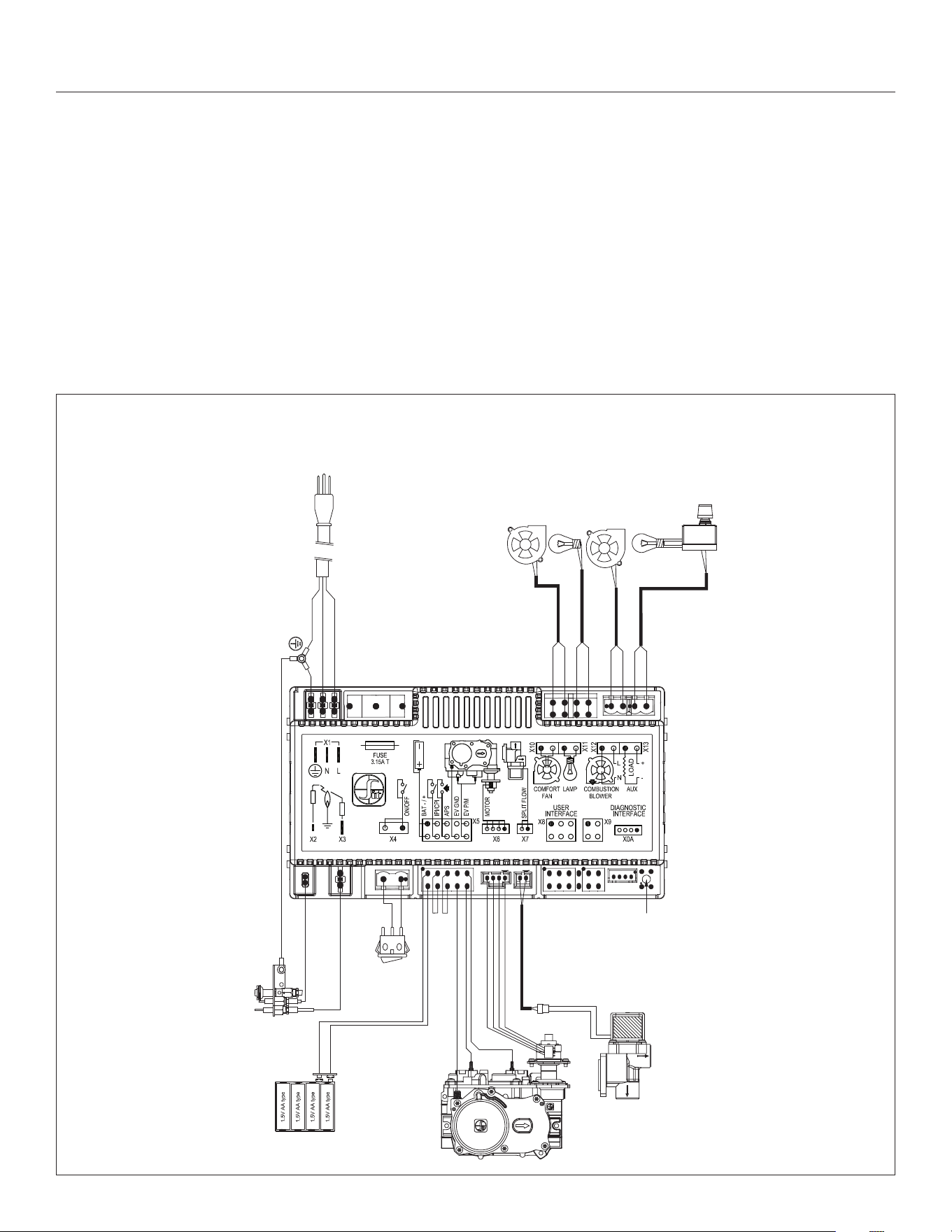
#BHM-44 R.1 August 2020 Hussong Mfg. Co., Inc. • Kozy Heat Fireplaces ELECTRICAL INFORMATION 55
9.0 ELECTRICAL INFORMATION
WARNING: Do not use this replace if any part has been under water.
Immediately call a qualied service technician to inspect this appliance
and to replace any part of the control system and any gas control that
has been under water.
WARNING - Electrical Grounding Instructions: This appliance is
equipped with a three-prong (grounding) plug for your protection
against shock hazard and should be plugged directly into a properly
grounded three-prong receptacle. Do not cut or remove the grounding
prong from this plug.
9.1 Electrical Specications
This appliance, when installed, must be electrically grounded in
accordance with local codes, or in the absence of local codes, with
the National Electrical Code, ANSI/NFPA 70, or the Canadian Electrical
Code, CSA C22.1.
9.2 Wiring Requirements
• The IFC System Module requires 120V of electricity and/or
batteries to operate.
• Using the battery back-up will operate the burner only.
• Fan component, top light kit, and auxiliary light kit (ember bed
light kit) will not function on battery back up power.
Figure 9.1, Wiring Schematics
MALE END
VARIABLE
SPEED FAN
VARIABLE LIGHT
[Top light kit]
APPLIANCE
GROUND STAR
BATTERY
PACK
885 PROFLAME
MAIN ON/OFF
SWITCH
PILOT
PILOT
BURNER
FLAME
SENSOR
IGNITER
SW1 BUTTON
(RED)
AUX (ON/OFF)
[Ember bed light kit]
POWER VENT
[optional]
540 SPLIT FLOW
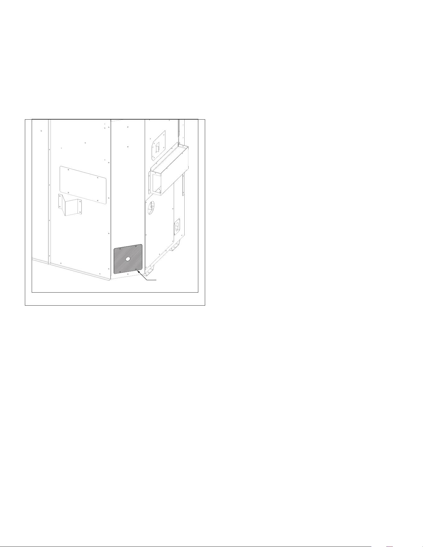
56 ELECTRICAL INFORMATION Hussong Mfg. Co., Inc. • Kozy Heat Fireplaces #BHM-44 R.1 August 2020
9.3 Outlet Junction Box
This appliance is equipped with a (4) outlet junction box, located on
the left side of the unit. There are outlets for connecting the Kozy
Power Vent (see #KPV manual for more information), the ember bed
light kit, and the control module.
Remove the (4) screws securing electrical access cover to the rebox
outer shell for access to the junction box. Reinstall when nished.
9.4 Ember Bed Light Kit (auxiliary)
CAUTION: Disconnect all electrical power from the replace before
performing this task.
ATTENTION: If converting to propane, complete the conversion before
installing any light kit components. Follow instructions provided with
the conversion kit (sold separately).
NOTE: To avoid damage and prolong the life of the halogen bulbs,
never touch with bare hands. Always use a soft cloth when handling.
9.4.1 Install Ember Bed Light Kit
1. Remove the safety barrier screen and glass frame assembly.
2. Remove the media tray.
3. Install (6) halogen bulbs (included in component packet) into
lamp bases.
4. Reinstall media tray.
5. Reinstall glass frame assembly and safety barrier.
Outlet junction
box access
Figure 9.2, Electrical Access on Left Side of Unit
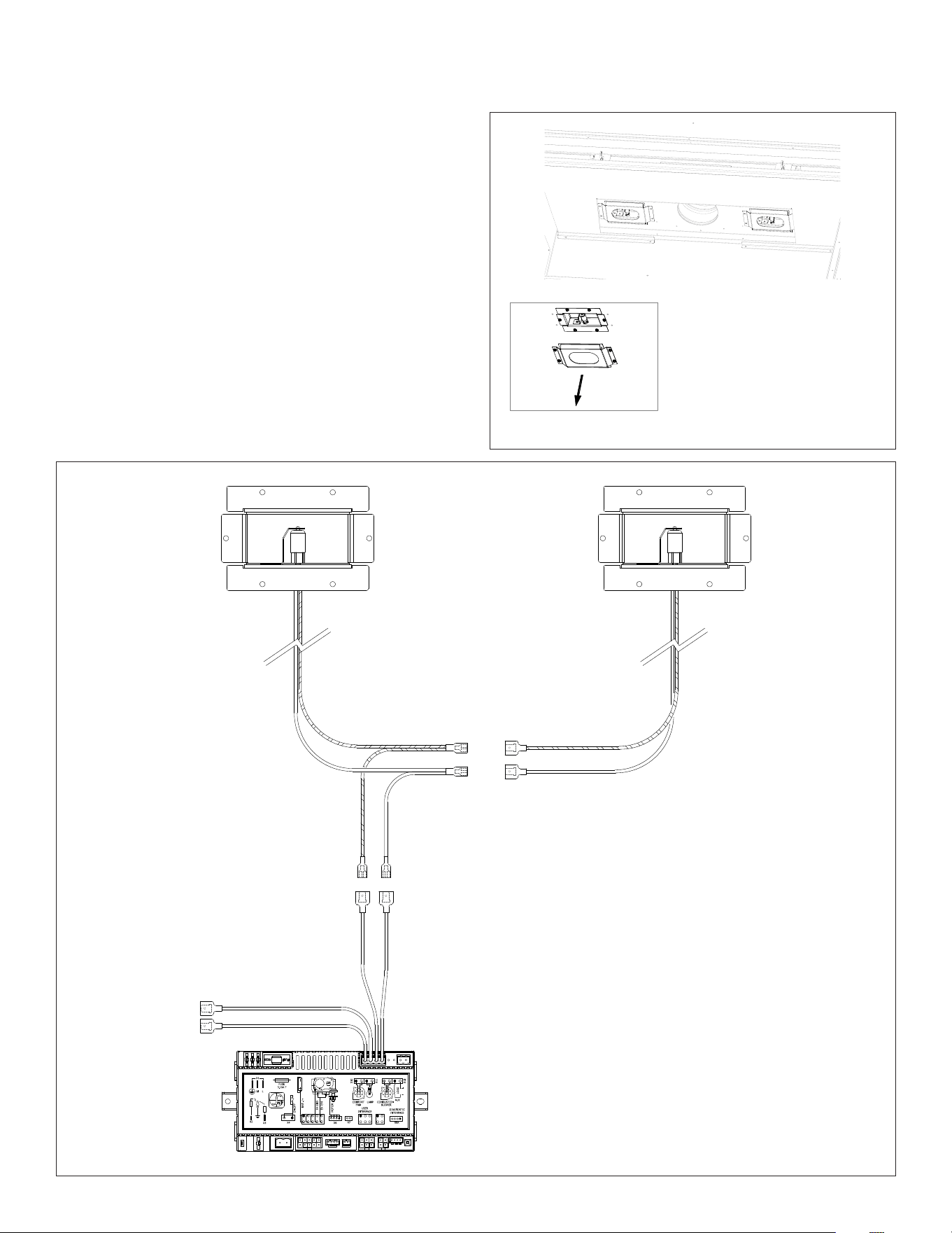
#BHM-44 R.1 August 2020 Hussong Mfg. Co., Inc. • Kozy Heat Fireplaces ELECTRICAL INFORMATION 57
9.5 Top Light Kit #600-TLK
CAUTION: Disconnect all electrical power from the replace before
performing this task.
NOTE: To avoid damage and prolong the life of the halogen bulbs,
never touch with bare hands. Always use a soft cloth when handling.
9.5.1 Install Top Light Kit
1. Remove the safety barrier screen and glass frame assembly (if
installed).
2. Remove the top light kit covers and its roped glass (8) screws
total. Save screws.
3. Install or replace (2) halogen bulbs (included with this kit) into
lamp bases.
4. Reinstall top light kit covers and its roped glass with (8) screws
previously removed.
5. Reinstall glass frame assembly and safety barrier screen.
Figure 9.3, Top Light Kit Location
RED MALE
CONNECTORS
YELLOW FEMALE
CONNECTORS
BLUE FEMALE
CONNECTORS
RED MALE
CONNECTORS
(from control module)
BLACK
WHITE
Figure 9.4, Top Light Kit Wiring
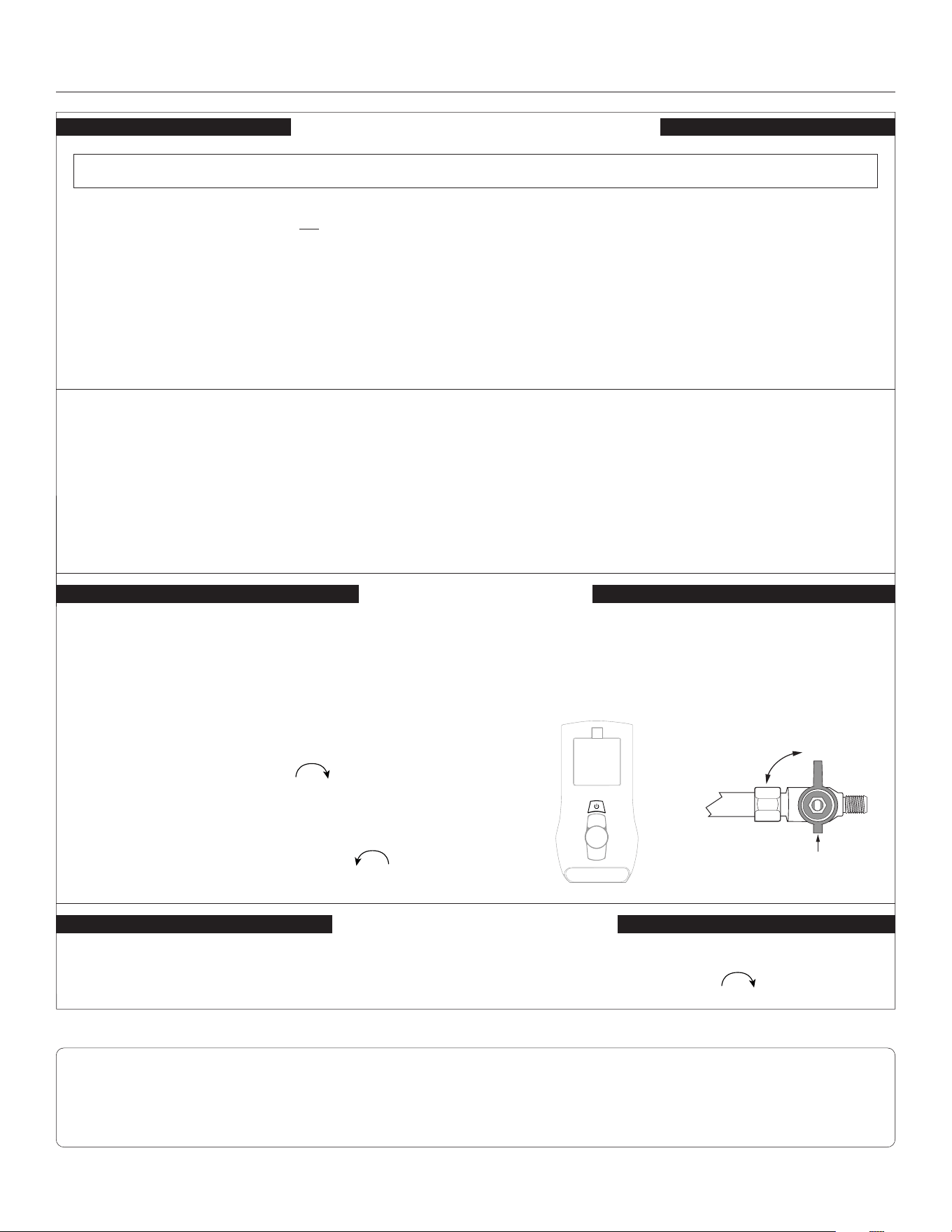
58 OPERATING INSTRUCTIONS Hussong Mfg. Co., Inc. • Kozy Heat Fireplaces #BHM-44 R.1 August 2020
10.0 OPERATING INSTRUCTIONS
WARNING
Do not operate appliance with the glass front removed, cracked, or
broken. Replacement of the glass should be done by a licensed or
qualied service person.
Under no circumstances should any solid fuel (wood, coal, paper,
cardboard, etc.) be used in this appliance.
Children and adults should be alerted to the hazards of high surface
temperature and should stay away to avoid burns or clothing ignition.
CAUTION
Clothing or other ammable material should not be placed on or near
the appliance.
Young children should be carefully supervised when they are in the
same room as the appliance. Toddlers, young children and others
may be susceptible to accidental contact burns. A physical barrier is
recommended if there are at risk individuals in the house. To restrict
access to a replace or stove, install an adjustable safety gate to keep
toddlers, young children and other at risk individuals out of the room
and away from hot surfaces.
WARNING: If you do not follow these instructions exactly, a re or explosion may result causing property damage, personal injury, or loss of life.
1. STOP! Read all the safety information above on this page.
2. Press the wireless remote OFF button.
3. Turn o all electric power to the appliance.
4. This appliance is equipped with an ignition device which
automatically lights the pilot. Do not try to light the pilot by
hand.
5. Locate the manual valve installed by your qualied service
technician.
6. Turn the manual valve clockwise to the OFF position.
7. Wait ve (5) minutes to clear out any gas. Then, smell
for gas, including near the oor. If you smell gas, STOP!
Follow ‘B’ in the safety information above. If you do not smell
gas, go to the next step.
8. Turn the manual valve counterclockwise to the ON
position.
9. Turn on all electric power to the appliance.
10. Press the wireless remote ON button.
11. If the appliance will not operate, follow the instructions, “To
Turn O Gas To Appliance” and call your service technician or
gas supplier.
OPERATING INSTRUCTIONS
NOTE
When this replace is initially lit, condensation will appear on the glass. This is normal in all gas replaces and will disappear after several
minutes. A paint smell will occur during the rst few hours of burning. It is recommended to leave the fan o during this period to help speed
the paint curing process. This replace may produce noises of varying degree as it heats and cools due to metal expansion and contraction. This
is normal, and does not aect the performance or longevity of the replace.
A. This appliance is equipped with an ignition device which
automatically lights the pilot. Do not try to light the pilot by
hand.
B. BEFORE OPERATING smell around the appliance area for gas.
Be sure to smell next to the oor because some gas is heavier
than air and will settle on the oor.
WHAT TO DO IF YOU SMELL GAS
• Do not try to light any appliance.
• Do not touch any electric switch; do not use any phone in
your building.
• Immediately call your gas supplier from a neighbor’s phone.
Follow the gas supplier’s instructions.
• If you cannot reach your gas supplier, call the re
department.
C. Use only your hand to turn the gas control manual valve. Never
use tools. If the valve will not turn by hand, do not try to repair
it; call a qualied service technician. Force or attempted repair
may result in a re or explosion.
D. Do not use this appliance if any part has been under water.
Immediately call a qualied service technician to inspect the
appliance and to replace any part of the control system and
any gas control that has been under water.
ON/OFF
ON
OFF
1. Press the wireless remote OFF button.
2. Turn o all electric power to the appliance if service is to be
performed.
3. Locate the manual valve installed by your qualied service
technician.
4. Turn the manual valve clockwise to OFF position.
FOR YOUR SAFETY READ BEFORE OPERATING
TO TURN OFF GAS TO APPLIANCE
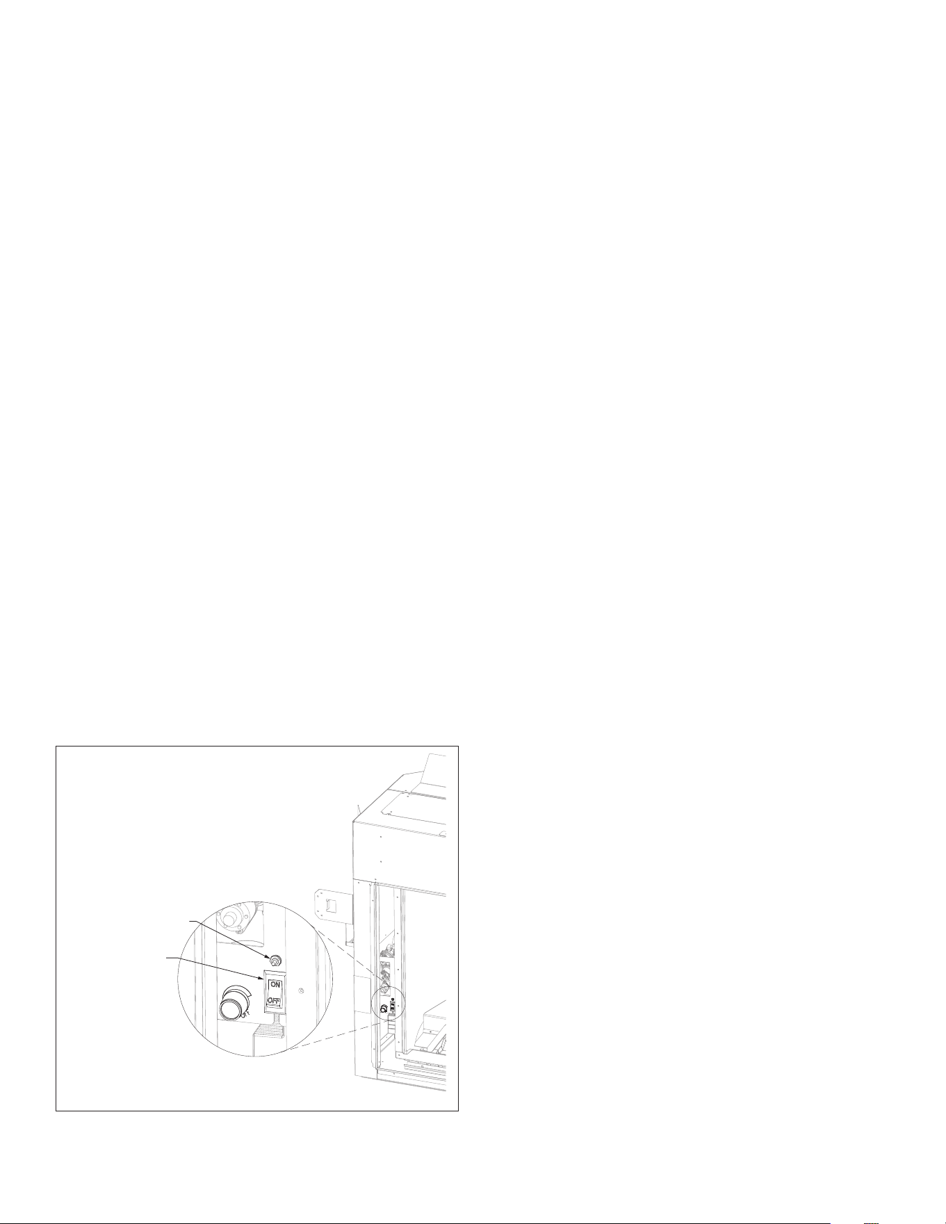
#BHM-44 R.1 August 2020 Hussong Mfg. Co., Inc. • Kozy Heat Fireplaces OPERATING INSTRUCTIONS 59
10.1 Setup Proame 2 IFC Module
1. Set the main ON/OFF rocker switch in the OFF position.
2. Install (4) AA batteries (not included) into backup battery holder
on the control module.
3. Install (3) AAA batteries (included in the components packet) in
the remote control battery bay, located at the base of the remote.
4. Connect the IFC Module to an AC power supply.
10.2 Initialize the Control System
IMPORTANT: Remove all packaging and combustible material from the
rebox before initializing the control system.
NOTE: Performing the next steps will initiate pilot start-up in manual
mode, where the pilot igniter will spark repeatedly. The pilot will ignite
if gas is supplied to the replace.
1. To access the ON/OFF toggle switch and remote learn button on
the left side of the unit, remove the safety barrier screen by lifting
up and out of its slots.
2. Locate the remote sync button on the control module access
switch on the left side of the replace. See Figure 10.1 below.
3. Press the remote sync button. The IFC module will BEEP (3) times
and illuminate an amber LED. This indicates the receiver is ready
to synchronize with the transmitter.
4. Within (5) seconds, push the ON/OFF button on the remote
control. The receiver will BEEP (4) times to indicate the
transmitter’s command is accepted, and is set to the transmitter’s
particular code. The pilot will automatically ignite.
5. Press the remote control ON/OFF button again. The pilot will
extinguish, conrming the remote control command. The control
system is now initialized.
6. Set the main ON/OFF toggle switch to ON position for remote
control operation of the main burner and replace features.
7. Reinstall safety barrier screen.
10.3 Reset the System for
Manual Operation
1. Access the toggle switch and remote learn button on the left side
of the unit by removing the safety barrier screen by lifting up and
out of its slots.
1. Set the ON/OFF rocker switch to OFF position.
2. Press and hold the remote sync button until it emits (3) beeps and
an amber LED is illuminated.
3. Within (5) seconds, press the remote sync button again. This
will close synchronization with the remote control. The pilot will
automatically light.
• Turn the main burner ON by setting the ON/OFF switch in ON
position. The main burner will only operate on HI.
• Turn the main burner OFF by setting the ON/OFF switch in the
OFF position. The pilot will remain lit even if burner is turned o,
provided CPI mode is turned on.
10.4 Automatic Safety Restart
• This system will execute an automatic turn OFF command for
approximately (5) seconds within (24) hours of a continued pilot
ame ignition to perform a safety check. This allows the system to
verify correct safety functions.
• After the turn OFF sequence is completed, the IFC module will re-
execute the latest command.
10.5 Backup Battery Operation
This appliance will operate on the backup battery pack when electric
power is interrupted, or in a power outage. The lifespan of the backup
batteries depend on various factors, such as the quality of the batteries,
number of ignitions, et cetera.
• When the backup battery pack is low, the IFC module will emit a
double-beep while receiving an ON/OFF command.
• No commands will be accepted after this alert until the back up
batteries are replaced.
• Once replaced, the IFC module will emit a ‘beep’ as soon as it is
powered.
Figure 10.1, ON/OFF Toggle Switch and Remote Learn Button Location
Remote learn button
ON/OFF toggle switch

60 OPERATING INSTRUCTIONS Hussong Mfg. Co., Inc. • Kozy Heat Fireplaces #BHM-44 R.1 August 2020
10.6 Control System 7 Day Timeout
• If you have your Proame 2 system set to CPI (continuous pilot
ignition) with 7 consecutive days without ignition of the main
burner, the pilot will turn o. This a standard safety feature of the
SIT Proame 2 system.
• Once you turn CPI on, the 7 day timer will start. If at any time
during the following 7 days your main burner ignites, it will reset
the timer back to 7 days.
• See Section 10.9.3 Pilot Ignition Selection (IPI/CPI) on page 61
for more information.
How to check if your system is set to CPI:
The LCD screen will display the snowake icon.
To select the preferred pilot ignition feature,
1. With the system in the OFF position, press the mode key to index
the CPI mode icon.
2. Press the up arrow key to activate CPI.
3. Press the down arrow key to return to IPI. A single ‘beep’ will
conrm reception of the command.
To Turn ON the appliance:
1. With the system in the OFF position, press the remote control
ON/OFF key to turn ON the appliance.
A single ‘beep’ will emit from the IFC module to conrm recep-
tion of the command.
The LCD screen will display all active icons, and the IFC module will
start the ignition sequence.
10.7 IFC Module Ignition Sequence
The IFC module will try (2) times for ignition, each lasting
approximately (60) seconds, with approximately (35) seconds
between each attempt.
1. With the system in OFF position, press the remote control ON/OFF
key. Approximately (4) seconds after this key is depressed, the IFC
module will generate sparks to the pilot hood.
2. First ignition attempt will generate sparks for (60) seconds.
3. If there is no ame ignition (rectication) within the (60) second
time frame, the IFC module will stop generating sparks for
approximately (35) seconds.
4. After (35) seconds of wait time, the IFC module will generate
sparks for another (60) seconds for the second ignition attempt.
5. If there is no positive rectication after (60) seconds, the IFC
module will go into a lock out. The red LED will blink (3) times, in
intervals, until the system is reset.
10.7.1 Reset IFC Module after Lockout
10.7.1.1 ON/OFF Rocker Switch
1. Set the ON/OFF rocker switch to the OFF position.
2. After approximately (2) seconds, move the switch to the ON
position. The ignition sequence will start again.
10.7.1.2 Remote Control ON/OFF Key
1. Press the remote control ON/OFF key to turn the system OFF.
2. After approximately (2) seconds, press the ON/OFF key again. The
ignition sequence will start again.
10.7.1.3 Cycling Flame
1. Press the remote control down arrow key during ame adjustment
mode to reduce the ame to OFF (indicated by OFF displayed on
the LCD screen).
2. After approximately (2) seconds, press the up arrow key. The
ignition sequence will start again.
10.8 Additional Diagnostic Information
Low Battery Condition (<4V) Remote Control:
• Battery Icon will appear on LCD remote control display.
• Replace batteries.
Low Battery Condition (<4V) Battery Backup:
• The red LED Indicator will blink (1) time in intervals.
• A low double-beep emits from the IFC control module when it
receives an ON/OFF command from the remote control.
• Replace Batteries.
Pilot Flame Error Condition:
• Red LED Indicator will blink (2) times in intervals. Contact your
dealer if this occurs.
System Lock Out Condition:
• Red LED Indicator will blink (3) times in intervals.
• Verify gas is turned on.
• Verify sensor is not shorted.
• Follow Section 10.2 Initialize the Control System on the previous
page.
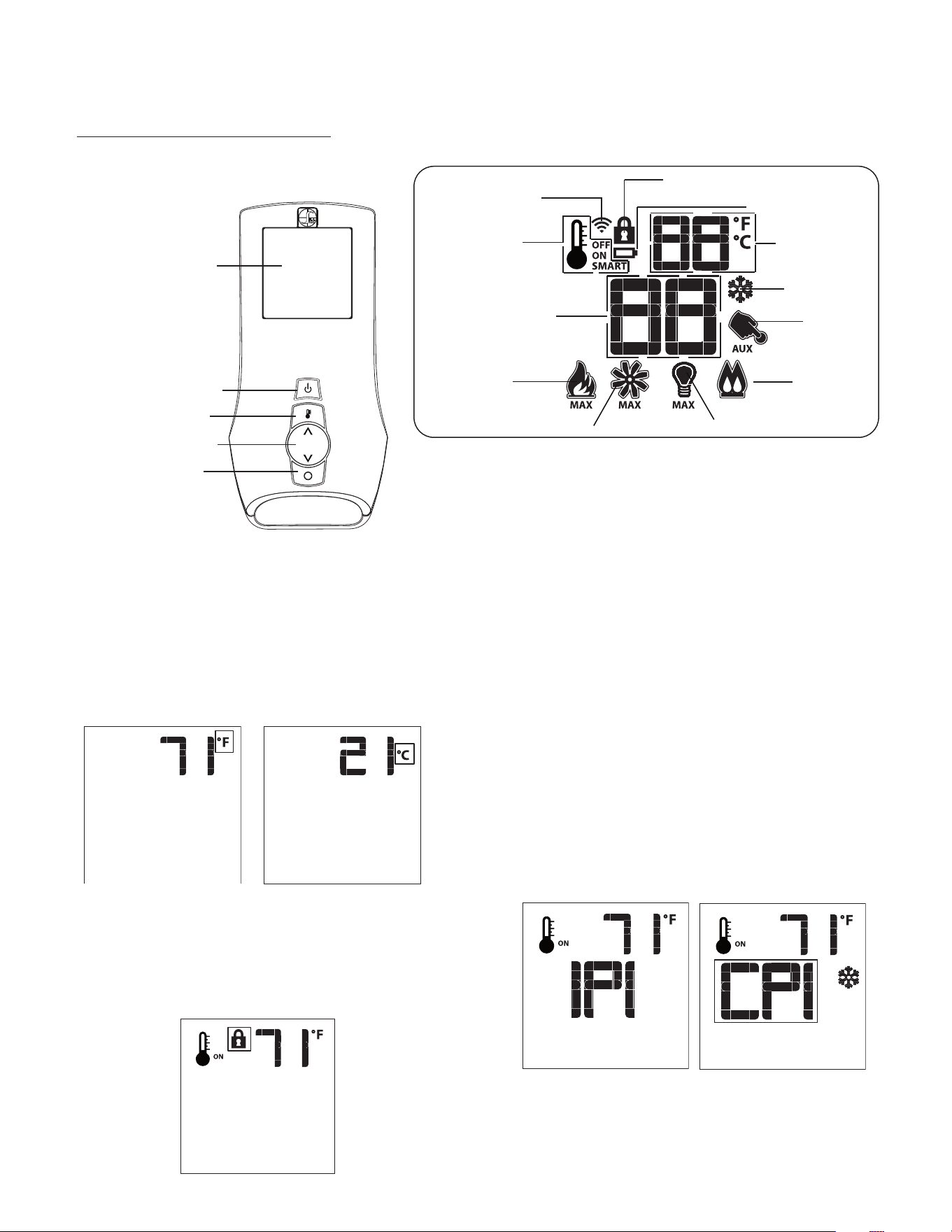
#BHM-44 R.1 August 2020 Hussong Mfg. Co., Inc. • Kozy Heat Fireplaces OPERATING INSTRUCTIONS 61
10.9 Remote Control Operation
10.9.1 Temperature Display
1. With the system in the OFF position, simultaneously press the
thermostat key and the mode key to change degrees from °F to
°C.
2. Visually check the LCD screen to verify either °F or °C is displayed
on the right side of the room temperature display.
10.9.2 Key Lock
This function locks the keys to avoid unsupervised operation. Once
activated, a lock icon will appear on the LCD screen.
1. Simultaneously press the mode key and the up arrow key to
activate or deactivate this function.
10.9.3 Pilot Ignition Selection (IPI/CPI)
This system has the option of a continuous (standing) pilot. This
features allows the system to change from a spark-to-pilot system
to the standing pilot option. The standing pilot will keep the rebox
warm and establish a draft in the vent, which allows the main burner
to ignite with less air-ow disruption.
When the system is OFF, the LCD screen will display the snowake icon
during the setup of either IPI or CPI mode. To select the preferred pilot
ignition feature,
1. With the system in the OFF position, press the mode key to index
the CPI mode icon.
2. Press the up arrow key to activate CPI.
3. Press the down arrow key vto return to IPI. A single ‘beep’ will
conrm reception of the command.
When the system is ON,
IPI mode: LCD screen will not display the snowake icon
CPI mode: LCD screen will display the snowake icon
PROFLAME 2 TRANSMITTER
LOW BATTERY ALARM
KEY LOCK
LIGHT ON
ROOM
TEMPERATURE
SET POINT
TEMPERATURE/LEVEL/STATE
FLAME ON
THERMOSTAT
OFF/ON/SMART
FAN
TRANSMISSION
SPLIT FLOW
CPI MODE
ON/OFF KEY
THERMOSTAT KEY
UP/DOWN ARROWS
MODE KEY
BLUE BACK
LCD DISPLAY
LCD DISPLAY
AUXILIARY
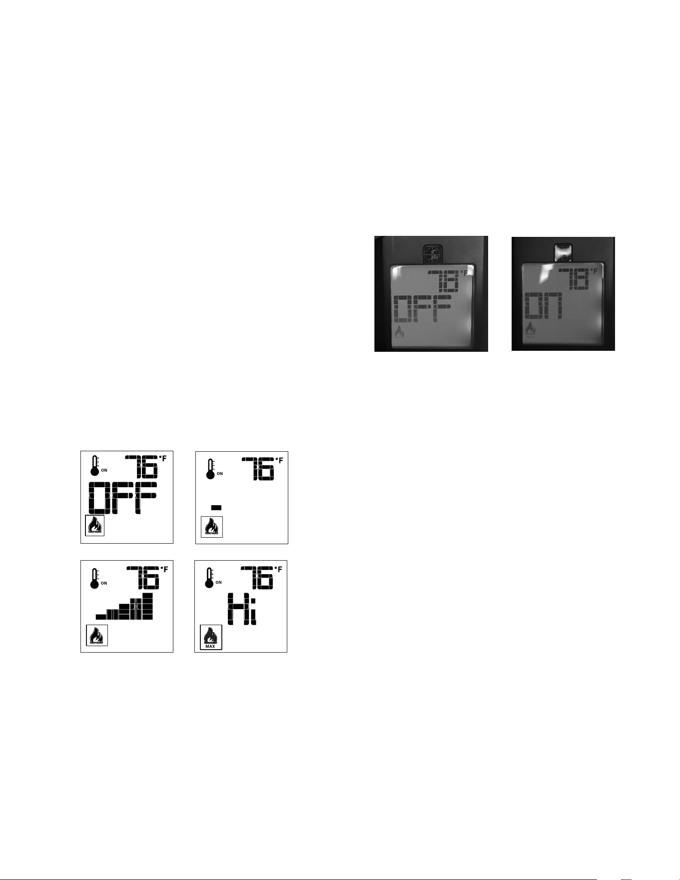
62 OPERATING INSTRUCTIONS Hussong Mfg. Co., Inc. • Kozy Heat Fireplaces #BHM-44 R.1 August 2020
10.9.4 Turn ON the Appliance
1. With the system in the OFF position, press the remote control
ON/OFF key to turn ON the appliance.
A single ‘beep’ will emit from the IFC module to conrm
reception of the command.
The LCD screen will display all active icons, and the IFC module will
start the ignition sequence.
10.9.5 Turn OFF the appliance
1. With the system in the OFF position, press the remote control
ON/OFF key to turn ON the appliance.
A single ‘beep’ will emit from the IFC module to conrm
reception of the command.
The LCD screen will only display the room temperature and its icon,
and the IFC module will turn o the main burner.
10.9.6 Remote Control Flame Adjustment
This control system has (6) ame levels. If the smart thermostat
operation is activated, then the manual adjustment of the ame
height will be disabled.
1. Verify the system is in the ON position and the ame level is set
at maximum.
2. Press the down arrow key once to reduce ame height by one
level until the ame is turned o.
3. Press the up arrow key once to increase ame height by one
step. If the up arrow key is pressed while the system is on, but
the ame is o, the ame will ignite on HI.
4. A single ‘beep’ will conrm reception of the command.
10.9.6.1 Deactivate Flame Modulation
1. Verify all (3) AAA batteries are installed in the remote control
battery bay.
2. Remove (1) AAA battery.
3. Press and hold the on/o key and the mode key at the same
time.
4. Reinsert (1) AAA battery.
5. While still holding the on/o key, let go of ONLY the mode key.
6. Index over to the ame graphic on the LCD screen to edit. Use
the up or down arrow key to choose ‘ON’ or ‘OFF’.
Flame Off
Flame Level 1
Flame Level 5 Flame Level Maximum
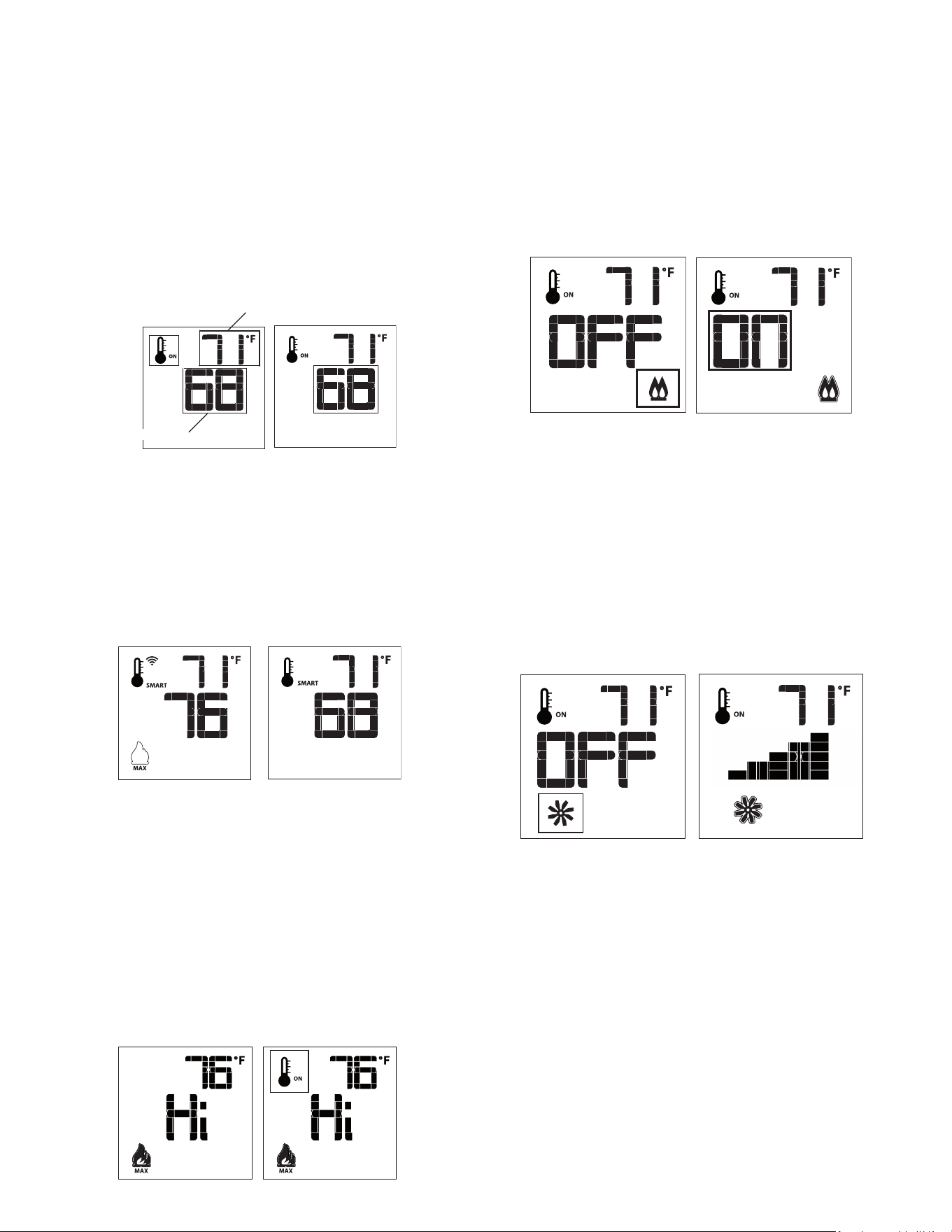
#BHM-44 R.1 August 2020 Hussong Mfg. Co., Inc. • Kozy Heat Fireplaces OPERATING INSTRUCTIONS 63
10.9.7 Remote Control Thermostat Operation
10.9.7.1 Room Thermostat
The remote control can operate as a room thermostat. The thermostat
can be set to a desired temperature to control a room’s comfort level.
To activate this function,
1. Press the thermostat key. The LCD screen will display a
temperature bulb graphic, the room temperature and set
temperature.
2. To adjust the set temperature, press the up or down arrow keys
until the desired temperature is displayed on the LCD screen.
10.9.7.2 Smart Thermostat
The smart thermostat function will adjust the ame height based
on the set temperature and the actual room temperature. The smart
thermostat function automatically adjusts the ame down when the
room temperature reaches the set point. To activate this function,
1. Press the thermostat key until the ‘SMART’ appears on LCD
screen on the right side of the temperature bulb graphic.
2. To adjust the set temperature, press the up or down arrow keys
until the desired temperature is displayed on the LCD screen.
10.9.7.3 Deactivate Remote Control
Thermostat Operation
The thermostat operation function can be deactivated. The remote
control will still operate the main burner on and o, and function
ame, fan, and light modulation. To deactivate this function,
1. Verify all (3) AAA batteries are installed in the remote control.
2. Remove (1) AAA battery.
3. While reinserting the battery, push and hold the thermostat key.
The temperature bulb graphic will not be displayed on the LCD
screen.
• To reactivate remote thermostat operation, follow the same key
sequence procedure above. The temperature bulb graphic will
reappear on the LCD screen.
SET TEMPERATURE
ROOM TEMPERATURE
10.9.8 Split Flow Control
The secondary burner is controlled by the split ow. To activate this
function,
4. Press the mode key to index to the split ow mode icon.
5. Press the up arrow key to activate the secondary burner.
6. Press the down arrow key to turn the secondary burner o. A
single ‘beep’ will conrm the reception of the command.
10.9.9 Fan Speed Control
Fan speed can be adjusted through (6) speeds. To activate this
function,
1. Press the mode key to index to the fan control icon.
2. Press the up or down arrow keys to turn on, o, or to adjust fan
speed.
Thermostat mode: Fan(s) have a (5) minute delay time when the
replace is let. This allows time for heat to build in replace before
fan operation. The fan will continue to operate for approximately (12)
minutes after the replace has been turned o.
Manual mode: Fan(s) will operate at previous setting. There is no
delay in start up or stop time.
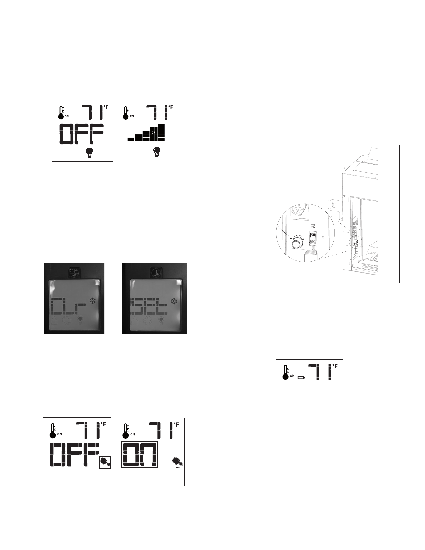
64 OPERATING INSTRUCTIONS Hussong Mfg. Co., Inc. • Kozy Heat Fireplaces #BHM-44 R.1 August 2020
10.9.10 Top Accent Light Kit
The top light intensity can be adjusted through (6) levels.
1. Press the mode key to index to the light icon.
2. Press the up or down arrow keys to adjust the intensity level.
3. A single ‘beep’ will conrm reception of the command.
10.9.10.1 Deactivate Light Kit Modulation
1. Verify all (3) AAA batteries are installed in the remote control
battery bay.
2. Remove (1) AAA battery.
3. Press and hold the on/o key and the mode key at the same
time.
4. Reinsert (1) AAA battery.
5. While still holding the on/o key, let go of ONLY the mode key.
6. Index over to the bulb graphic on the LCD screen to edit. Use the
up or down arrow key to choose ‘SET’ or ‘CLR’.
10.9.11 Ember Bed Light Kit (auxiliary)
The auxiliary function controls ON/OFF function the ember bed light
kit. To activate this function,
1. Press the mode key to index to the AUX icon.
2. Press the up arrow key to turn the ember bed light kit ON.
3. Press the down arrow key to turn the ember bed light kit OFF.
4. A single ‘beep’ will conrm reception of the command.
10.9.11.1 Adjust Ember Bed Light Kit Intensity
The ember bed light kit intensity can be adjusted by using the ember
bed light kit modulator knob located on the left side of the rebox. To
adjust,
1. Remove the safety barrier screen by lifting the screen up and out
of the slots.
2. Turn the knob counterclockwise to decrease the light intensity.
3. Turn the knob clockwise to increase the light intensity.
4. Reinstall safety barrier screen when nished. Raise the safety
screen front slightly into slots and allow tabs to lower into
position.
10.9.12 Remote Control Low Battery Detection
Remote control battery lifespan depends on various factors including
battery quality, number of ignitions, changes to room thermostat set
point, etcetera.
• When the remote control batteries are low, a battery icon will
appear on the LCD display before all battery power is lost.
• When the batteries are replaced, this icon will disappear.
Ember bed light kit
modulator knob
Figure 10.2, Ember Bed Light Kit Modulator Knob
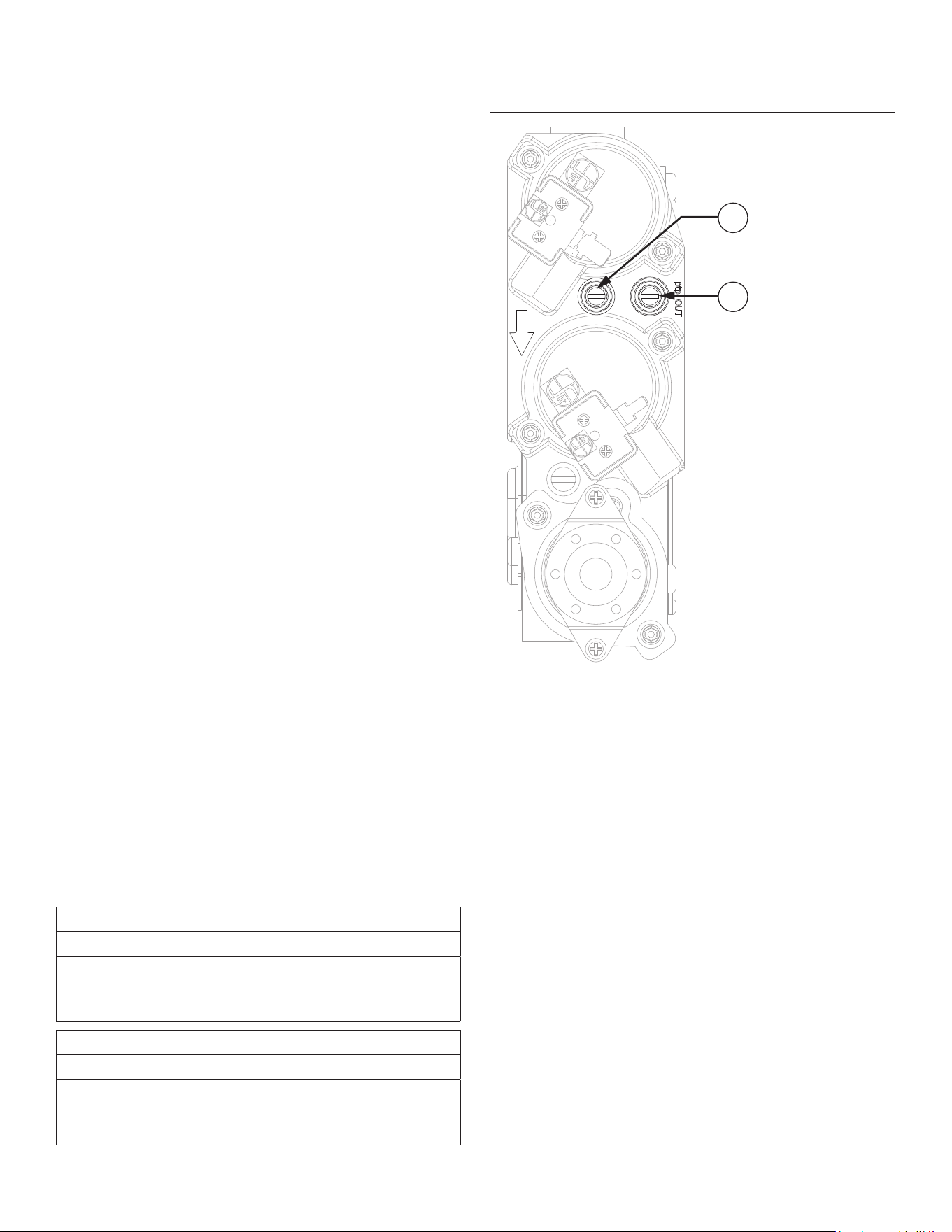
#BHM-44 R.1 August 2020 Hussong Mfg. Co., Inc. • Kozy Heat Fireplaces ADJUSTMENT 65
11.0 ADJUSTMENT
11.1 Pressure Testing
NOTE: The appliance and its appliance main gas valve must be
disconnected from the gas supply piping system during any pressure
testing of the system at test pressures in excess of ½ psi (3.5 kPa).
IMPORTANT: Pressure check taps for manifold (outgoing) and inlet
(incoming) pressure have been incorporated into the valve. The
pressure tap marked OUT measures outgoing pressure. The pressure
tap marked IN measures incoming pressure.
11.1.1 Inlet Pressure Test
NOTE: Make sure to apply these incoming pressure test with all other
gas appliances on, or at full capacity, in the house for proper pressure
reading.
IMPORTANT: If the inlet pressure reading is too high or too low, contact
the gas company. Only a qualied gas service technician should adjust
incoming gas pressure.
1. Loosen the inlet (IN) pressure tap by turning screw counter-
clockwise. See (A) in Figure 11.1.
2. Attach manometer using a ¼” (6mm) I.D. hose.
3. Light pilot and burner. Check pressure to ensure it is between
the minimum and maximum recommended pressure settings.
4. Turn o burner and pilot.
5. Disconnect hose and tighten the inlet (IN) pressure tap by
turning screw clockwise. Screw should be snug. Do not over
tighten.
6. Relight pilot and burner. Then reattach manometer to the
inlet pressure tap (A) to verify the tap is completely sealed.
Manometer should read no pressure.
11.1.2 Manifold Pressure Test
1. Light pilot.
2. Loosen manifold (OUT) pressure tap by turning screw counter-
clockwise. See (B) in Figure 11.1.
3. Attach manometer to pressure tap using a ¼” (6mm) I.D. hose.
4. Light burner. Check manometer reading.
5. Turn burner and pilot o.
6. Disconnect manometer hose and tighten the manifold (OUT)
pressure tap by turning screw clockwise. Screw should be snug.
Do not over tighten.
7. Attach the manometer to the manifold pressure tap (B) to verify
it is completely sealed. The manometer should read no pressure
when pilot and burner are on.
Table 11.1, Inlet Pressures
Fuel Natural Gas Propane
Gas Supply Min - Max Min - Max
Inlet Pressure
Tap (A)
5” - 10.5” WC
(1.25 - 2.62 kPa)
12” - 13” WC
(2.99 - 3.24 kPa)
Table 11.2, Manifold Pressure
Fuel Natural Gas Propane
Gas Supply Low - High Low - High
Manifold Pressure
Tap (B)
1.1” - 3.8” WC
(0.27 - 0.95 kPa)
2.9” - 11” WC
(0.72 - 2.74 kPa)
Figure 11.1, Pressure Check Taps
Inlet pressure
tap
Manifold pressure
tap
A
B
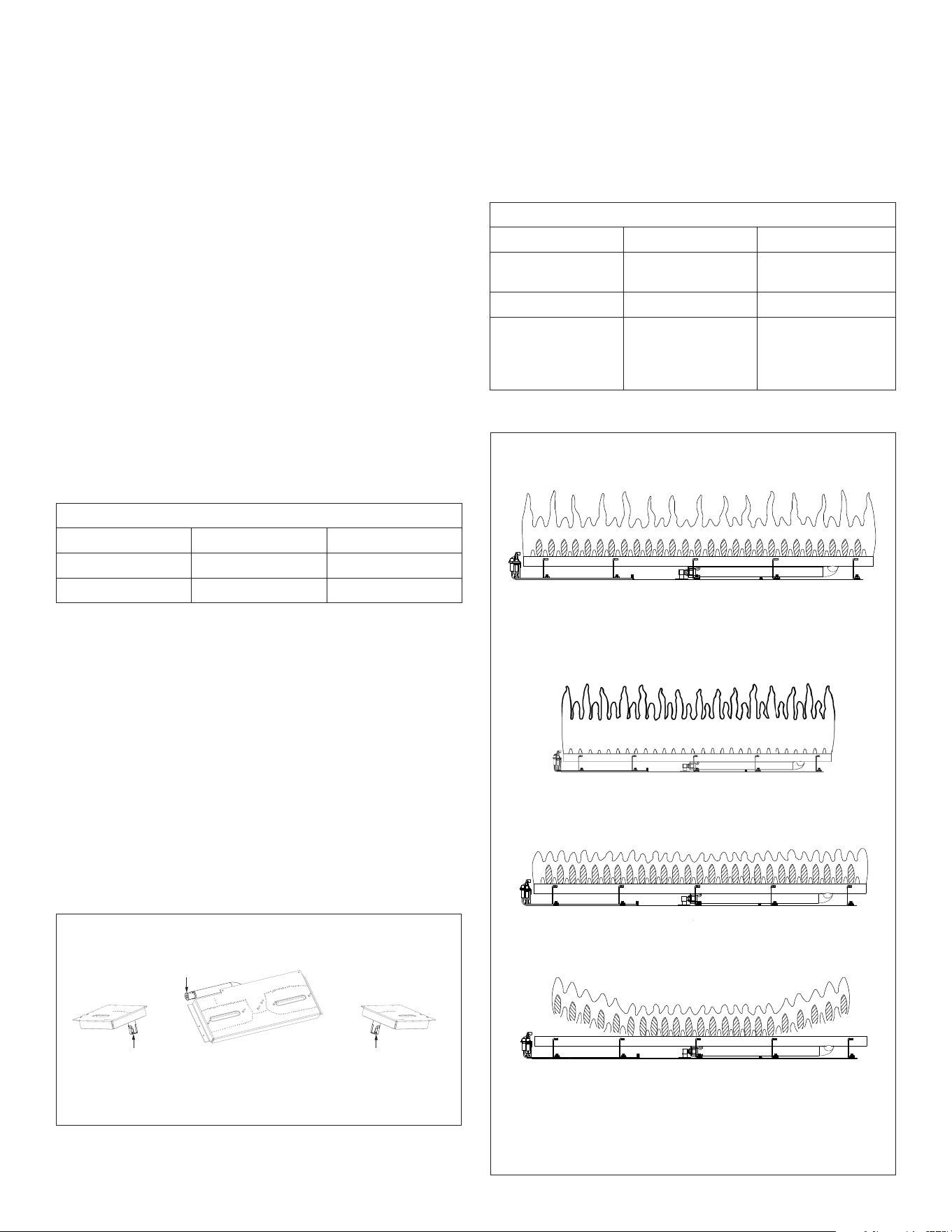
66 ADJUSTMENT Hussong Mfg. Co., Inc. • Kozy Heat Fireplaces #BHM-44 R.1 August 2020
11.2 Burner Flame Adjustments
WARNING: To avoid property damage or personal injury, allow the
replace ample time to cool before making any adjustments.
Burner ame appearance and characteristics are aected by
altitude, fuel quality, venting conguration, and other factors. After
installation, this appliance may need additional adjustments to
achieve optimum ame appearance and visual aesthetics.
11.2.1 Burner Venturi
WARNING: VENTURI ADJUSTMENT MUST BE DONE BY A QUALIFIED
SERVICE TECHNICIAN.
NOTE: Burner venturi air shutter settings have been factory set. Refer
to Table 11.3.
When this appliance is rst lit, the burner ames will appear blue.
During the rst 15 minutes of operation, ame appearance will
gradually turn to the desired yellow appearance. If the ames remain
blue, or become dark orange with evidence of sooting (black tips),
adjustment of the air shutter opening may be necessary.
Regardless of venturi orientation, closing the air shutter will achieve a
desired yellow ame, but may produce soot on the glass. Opening the
air shutter will cause a short, blue ame that may lift o the burner.
Table 11.3, Factory Set Venturi Openings
Fuel Center Burner Venturi Side Burner Venturi
Natural Gas 3/16” (4.763mm) 3/16” (4.763mm)
Propane 1/2” (12.7mm) 5/8” (15.88mm)
11.2.1.1 Venturi Adjustment
NOTE: If soot is present on the logs, check log placement (section 8.4,
pg. 51) before adjusting the venturi.
1. Remove the safety barrier screen and glass frame assembly.
2. Remove log set, lava rock, panel set, and media tray.
3. Remove the log rack and log stop brackets.
4. Remove burner link brackets.
5. Remove the side burners and center burners.
6. Release the burner tube venturis o the burner orices.
7. Loosen screw on venturi and adjust as necessary. Re-tighten
screw.
8. Reinstall all components previously removed.
IMPORTANT: Slight adjustments to the venturi opening will create
dramatic results. Adjust at slight increments until desired look is
achieved. Always burn the replace for at least 15 minutes, and
allow the appliance ample time to cool before making any further
adjustments.
Table 11.4, Venturi Adjustment Guidelines
Flame Characteristic Cause Solution
Dark, orange ame
with black tips
Venturi closed too far Open venturi slightly
Short, blue ames Venturi open too far Close setting slightly
Lifting (ghosting)
ames
Gas pressure too high
Venturi closed too far
Check manometer
settings
Open venturi setting
slightly
Figure 11.2, Burner Venturis
Figure 11.3, Flame Appearance and Characteristics
Lazy, yellow flames - no adjustment necessary
Ideal Flame Appearance
Side burner venturi
(left side)
Center burner venturi
Side burner venturi
(right side)
Venturi(s) settings closed too far. Open venturi(s) slightly.
Dark, orange flames with black tips
Venturi(s) open too far. Close venturi settings(s) slightly.
Short, blue flames
Venturi settings(s) closed too far. Open venturi(s) slightly
OR gas pressure too high - check manometer settings
Lifting (ghosting) flames
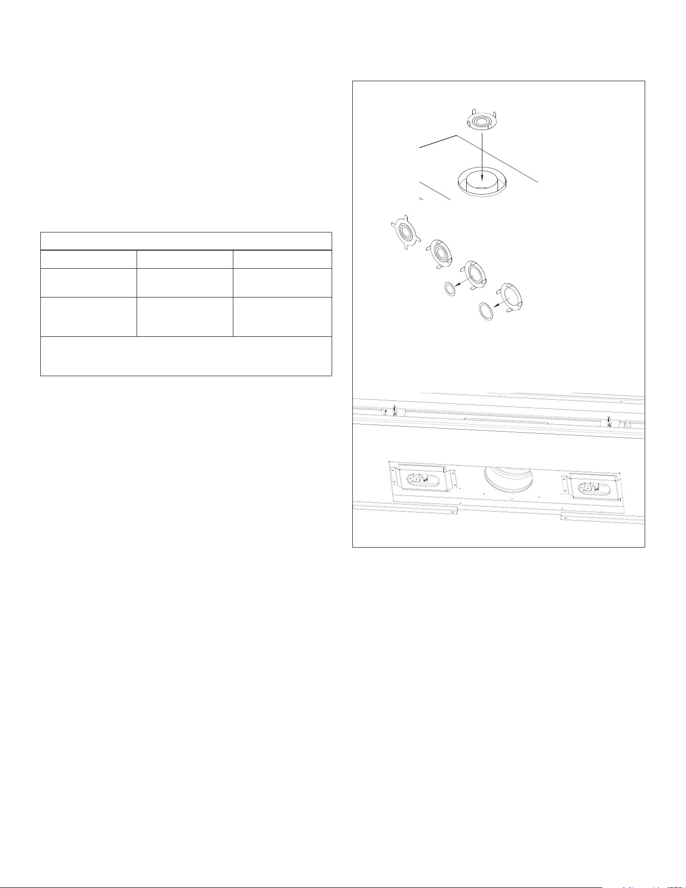
#BHM-44 R.1 August 2020 Hussong Mfg. Co., Inc. • Kozy Heat Fireplaces ADJUSTMENT 67
11.2.2 Vent Restriction (after installation)
WARNING: To avoid property damage or personal injury, allow the
replace ample time to cool before making any adjustments.
WARNING: Improper vent installation may cause the burner ames
to lift or “ghost.” Perform a visual check on ame appearance after
restriction adjustment to ensure proper performance.
Vertical terminations may display an active, compact ame. If this
appearance is not desirable, a restrictor plate may need to be installed
or modied after vent termination installation. Access to the vent exit
for restriction can be reached through the replace bae. Allow the
replace to burn for 15 minutes before making any adjustments.
Table 11.5, Restrictor Plate Adjustment Guidelines
Flame Appearance Draft Problem Solution
Short, ickering Excessive draft
Not enough restriction
Add restrictor plate
Lifting or ghosting* Insucient draft Remove inner ring(s)
on restrictor plate, or;
remove restrictor plate
*If ames continue to lift or ghost after opening the restrictor plate
and verifying correct vent installation, shut o the gas supply and call a
qualied service technician.
11.2.2.1 Restrictor Plate Installation
1. Remove the safety barrier and the glass frame assembly.
2. Locate the 5” (127mm) exhaust pipe in the rebox ceiling.
3. Bend the tabs on the restrictor plate (included in components
packet) to approximately 80° angles. This will create tension
when the restrictor plate is inserted into the exhaust pipe.
4. Insert restrictor plate into the 5” (127mm) exhaust pipe with the
tabs pointing towards you.
5. Reinstall all components previously removed.
11.2.2.2 Restrictor Plate Modication
1. Remove the safety barrier and the glass frame assembly.
2. Remove the restrictor plate by pulling it down and out of the 5”
(127mm) exhaust pipe. Make necessary modications to achieve
desired ame appearance.
3. Insert restrictor plate into the 5” (127mm) exhaust pipe with the
tabs pointing towards you.
4. Reinstall all components previously removed.
Figure 11.4, Vent Access and Restrictor Plate
Restrictor Plate
Slide restrictor into exhaust pipe on
top of replace with the tabs facing
towards you prior to attaching venting
Bend tabs to approx. 80° angles to create
tension to hold itself in place when installed
Remove innermost circle
to create less restriction
Remove all inner rings for
the least restriction
Insert restrictor plate into 5” (127mm) exhaust pipe in rebox ceiling with
tabs facing towards you
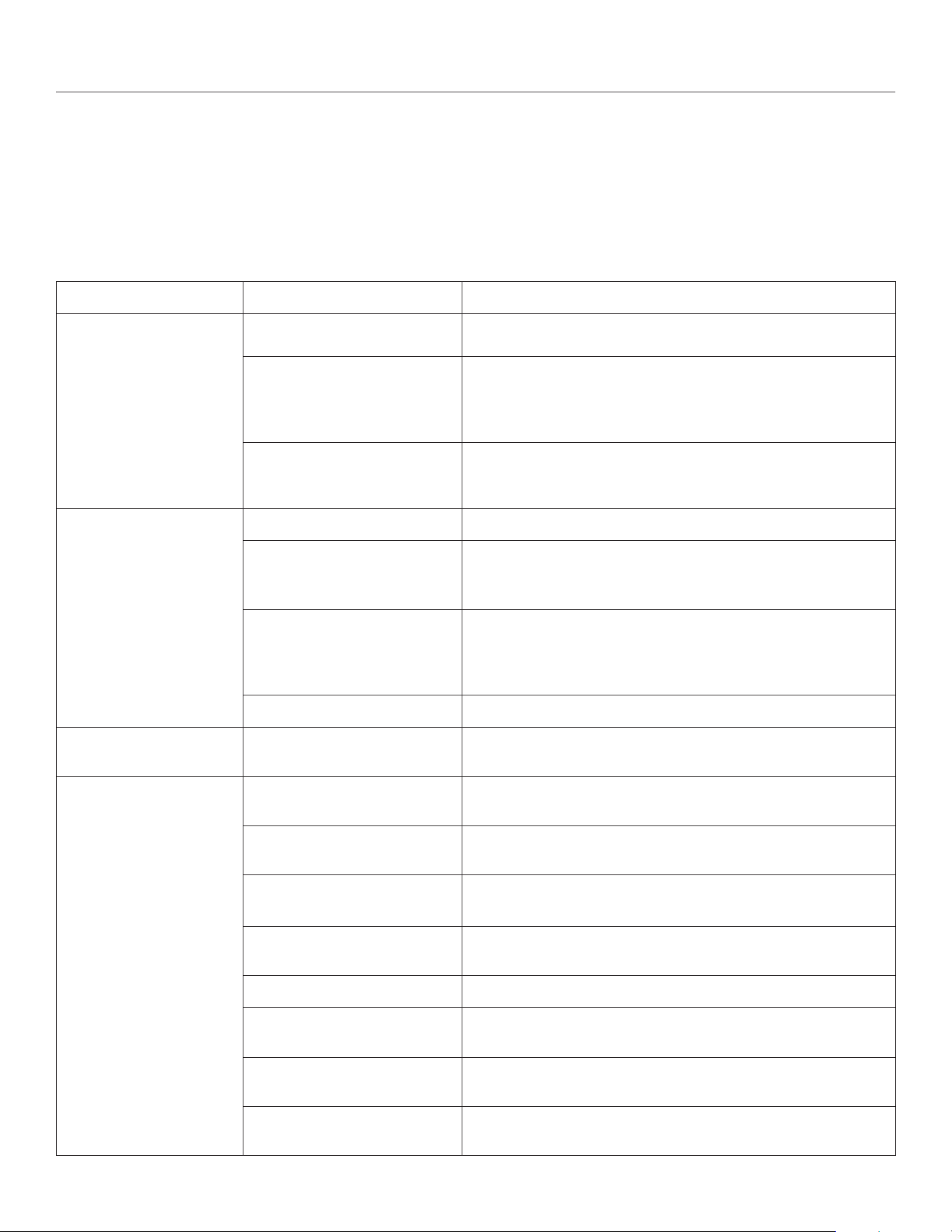
68 TROUBLESHOOTING Hussong Mfg. Co., Inc. • Kozy Heat Fireplaces #BHM-44 R.1 August 2020
12.0 TROUBLESHOOTING
ATTENTION: Troubleshooting must be performed by a qualied
technician.
Before proceeding with the steps in the following troubleshooting
guide,
• Verify proper 120VAC power supply to the control module.
• Verify the control module battery pack and the remote control
batteries are fresh and installed with correct polarity.
• Verify all connections between the wire harnesses and the
system components are proper and positive.
• Verify the communication link is established between the remote
control and the IFC module.
• Verify inlet pressure meets the recommended inlet pressure. If
necessary, adjust line pressure regulator.
Issue Cause Solution
Pilot will not light
Electrical power interrupted or
disconnected
Restore electrical power to appliance or use battery back-up.
Wiring disconnection
Ensure batteries are fully charged if using battery back-up as power
source.
Use wiring schematic in this manual to determine that all wiring
connections are secure and correct.
Gas supply turned o
Check remote shut-o valves from the appliance. Usually there is a valve
near the main gas line. There may be more than (1) valve between the
appliance and main gas line.
Pilot will not stay lit No propane in tank Check propane tank. Rell if necessary.
Low gas pressure Consult a plumber or a gas supplier.
Can be caused by situations such as a bent line, too narrow diameter or
pipe, or a low line pressure.
Pilot ame not making contact
with the ame rectication sensor
on the pilot assembly
Verify the pilot ame envelopes the top of the ame sensor and extends
far enough onto burner for ignition.
To adjust pilot ame, turn pilot adjustment screw on the gas valve
clockwise to decrease ame, and counterclockwise to increase ame.
Pilot adjustment screw not sealed Seal pilot adjustment screw. Do not over-tighten.
Pilot ame always on, or
will not extinguish
Control system set to CPI mode Set control system to IPI mode.
Main burner ame will not
light
ON/OFF rocker switch in OFF
position
Switch rocker switch to ON position.
Gas supply turned o Check for multiple shut-os in the supply line. Verify gas supply is turned
on.
Low gas supply Consult with plumber or gas supplier.
Check propane tank. Rell if necessary.
Wiring disconnection or improper
wiring
Check for faulty or incorrect wiring. Refer to Section 9.0 Electrical
Information on page 67.
Plugged main burner orice Remove blockage.
Pilot ame Verify the pilot ame is properly directed to ignite burner. See pilot
ame troubleshooting above.
Remote control not working
properly
Replace batteries.
No call for heat
Verify remote control is powered ON and thermostat operation is turned
OFF.
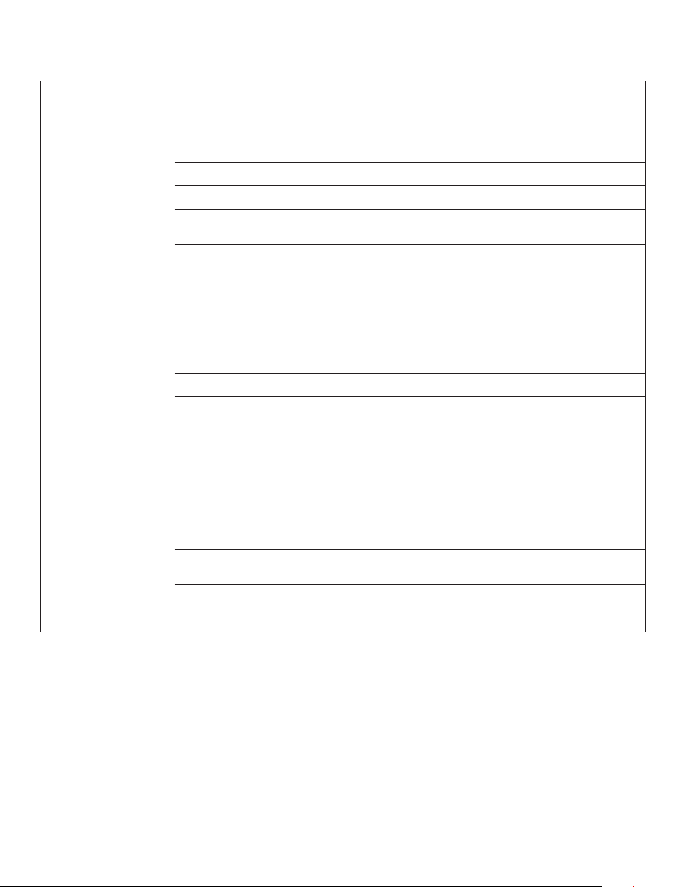
#BHM-44 R.1 August 2020 Hussong Mfg. Co., Inc. • Kozy Heat Fireplaces TROUBLESHOOTING 69
Issue Cause Solution
Pilot and burner extinguish
while in operation
No propane in tank Check propane tank. Rell if necessary.
Incorrect glass assembly
installation
Refer to Section 8.1 Glass Frame Assembly on page 49.
Incorrect vent cap installation Adjust if necessary.
Vent cap blockage Remove debris if necessary.
Improper pitch on horizontal
venting
¼” (6mm) rise per foot (30cm) is required on horizontal venting
Exhaust vent pipe leaking exhaust
gases back into rebox
Check for leaks and repair if necessary.
Excessive draft A restrictor may need to be installed or modied. Refer to Section 11.2.2
Vent Restriction (after installation) on page 67.
Soot appears on glass Improper log placement Refer to Section 8.5 #BH44-500 Log Set Installation on page 51.
Improper venturi setting Venturi air shutter may need to be opened slightly to allow more air into
the gas mix. Refer to Section 11.2.1 Burner Venturi on page 66.
Incorrect vent cap installation Adjust if necessary.
Vent cap blockage Remove debris if necessary.
Flame burns blue and lifts
o burner
Improper venturi setting Venturi air shutter may need to be opened slightly to allow more air into
the gas mix. Refer to Refer to Section 11.2.1 Burner Venturi on page 66.
Incorrect vent cap installation Adjust if necessary.
Blockage or leakage of the vent
system
Check the vent pipes for leaks, and the vent cap for debris. Repair the
vent pipes or remove debris from vent cap, if necessary.
No reaction to command Battery back batteries or remote
control batteries low
Replace batteries.
No communication between
remote control and IFC module
Reprogram remote control to IFC module. Refer to Section 10.2 Initialize
the Control System on page 59..
A maximum number of failed
ignitions or ame restorations has
been reached
Reset IFC module. Refer to Section 10.7 IFC Module Ignition Sequence
on page 60.

70 MAINTENANCE
Hussong Mfg. Co., Inc. • Kozy Heat Fireplaces #BHM-44 R.1 August 2020
13.0 MAINTENANCE
ATTENTION: Installation and repair should only be done by a qualied
service person. The appliance should be inspected before use and at
least annually by a professional service person. More frequent cleaning
might be required due to excessive lint from carpeting, bedding
material, et cetera. It is imperative that control compartments, burners,
and circulating air passageways of the appliance be kept clean. Use a
vacuum to clean all components.
WARNING: The appliance area must be kept clear and free from
combustible materials, gasoline and other ammable vapors and
liquids.
13.1 Firebox
Performed by: Qualied Service Person
Frequency: Annually
Action:
• Vacuum and clean any debris in the rebox that is not supposed
to be there.
• Inspect and operate the bottom latch assembly. Verify the
assembly is free from obstruction to operate. The handles must
have spring tension but be able to move forward freely.
13.2 Fan
CAUTION: Label all wires prior to disconnection when servicing
controls. Wiring errors can cause improper and dangerous operation.
Verify proper operation after servicing.
Performed by: Qualied Service Person
Frequency: Every 6 months
Action:
• Disconnect the fan from electrical current and vacuum.
• The bearings are sealed and require no oiling.
13.3 Vent System
NOTE: If the vent-air intake system is disassembled for any reason,
reinstall per instructions provided with installation. If Installing Kozy
Power Vent (#KPV), please reference the manual included with the kit.
For natural draft vent installation, refer to Section 7.0 Venting on page
43..
Performed by: Qualied Service Person
Frequency: Annually
Action:
• Examination of the vent system is required.
• The ow of combustion and ventilation air must not be
obstructed.
13.4 Glass Assembly
CAUTION: Do not operate appliance with the glass assembly removed,
cracked, or broken. Use protective gloves to handle any broken or
damaged glass assembly components.
WARNING: Do not use substitute materials.
WARNING: Avoid striking or slamming glass assembly. Avoid abrasive
cleaner. DO NOT clean glass while it is hot.
IMPORTANT: Any safety screen, guard, or barrier removed for servicing
the appliance must be replaced prior to operating the appliance.
Performed by: Homeowner
Frequency: Annually
Action:
• Prepare a work area large enough to accommodate the glass
assembly on a at, stable surface.
• Remove safety screen and glass frame assembly.
• Clean glass window with a suitable replace glass cleaner using
a soft cloth. Abrasive cleaners must not be used. Be careful not to
scratch the glass when cleaning.
• Reinstall glass assembly and safety screen. Do not operate
replace without safety screen.
Performed by: Qualied Service Person
Frequency: Annually
Action:
• Clean glass window with a suitable replace glass cleaner using
a soft cloth. Abrasive cleaners must not be used. Be careful not to
scratch the glass when cleaning.
• Inspect the glass for cracks, scratches, and nicks.
• Verify the glass assembly is properly intact and not damaged.
• Replace the glass and the assembly #701-059T as necessary.
• Only Hussong Mfg. Co., Inc. will supply the replacement of glass
assembly as a complete unit.
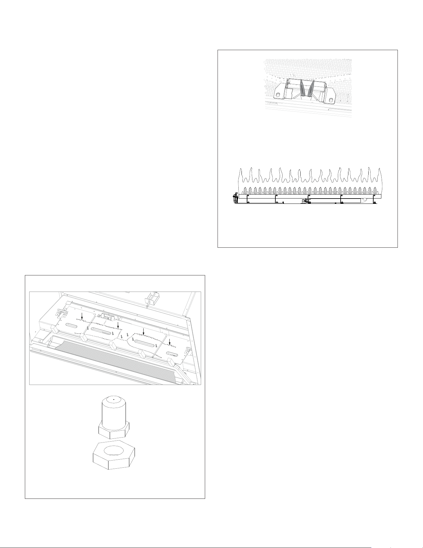
#BHM-44 R.1 August 2020 Hussong Mfg. Co., Inc. • Kozy Heat Fireplaces
MAINTENANCE 71
13.5 Burner and Pilot System
Certain components may be removed for easier access to the control
compartment. Refer to Section 8.5 Control Board Access, Removal and
Installation on page 53 for instructions. Verify gas supply is turned
on and lled. Consult with plumber or gas supplier as necessary.
Performed by: Qualied Service Person
Frequency: Annually
Action:
• Vacuum all components of the burner system.
• Check all accessible gas-carrying tubes, connections, pipes and
other components for leaks.
• Inspect the operation of the ame safety system Pilot or Flame
rectication device. Visually check pilot light when in operation.
• Inspect and ensure the lighting of the main burner occurs within
(4) seconds of the main gas valve opening. Check for faulty or
incorrect wiring and correct or replace as necessary. Inspect
primary air openings (burner ports) for blockage, especially near
the pilot.
• Visually check burner ame pattern when in operation. Flames
should be steady, not lifting or oating.
• Test and measure the ame failure response time of the ame
safety system. It must de-energize the safety shuto in no more
than (30) seconds.
Lazy, yellow flames
Ideal Flame Appearance
Figure 13.1, Burner System
Figure 13.2, Pilot and Burner Correct Flame Appearance
Burner orice
Correct pilot flame appearance
Burner Ports
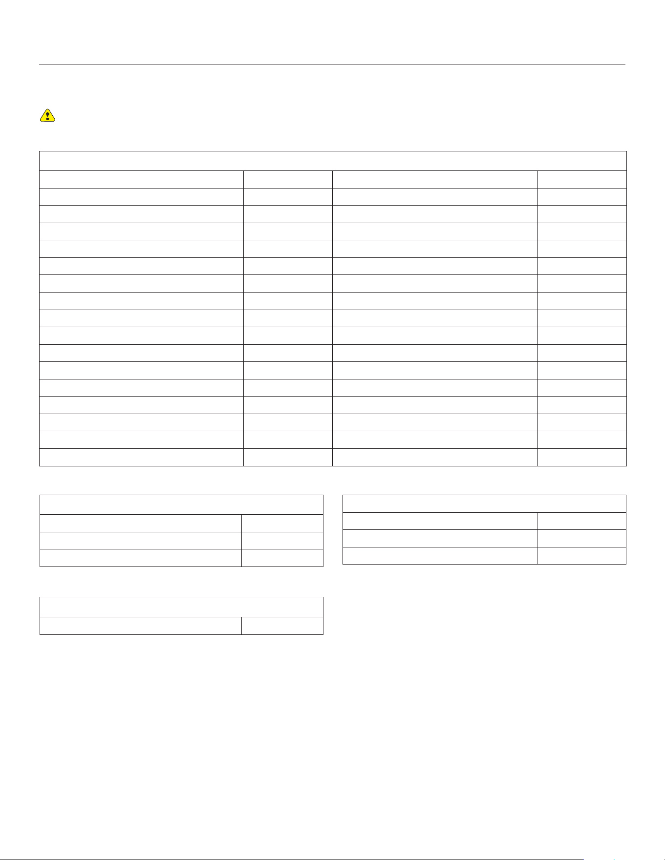
72 REPLACEMENT PARTS LIST Hussong Mfg. Co., Inc. • Kozy Heat Fireplaces #BHM-44 R.1 August 2020
14.0 REPLACEMENT PARTS LIST
Replacement parts are available through your local dealer. Contact your local dealer for availability and pricing.
BHM-44 CONTROL BOARD AND PARTS
Control Board - Natural Gas BH44-170 Pilot Orice - Propane #.014 LP 700-114
Control Board - Propane BH44-171 Valve Step Motor - Natural Gas 700-504
SIT IPI Gas Valve - Natural Gas 700-567 Valve Step Motor - Propane 700-504-1
SIT IPI Gas Valve - Propane 700-567-1 24” WhisperFlex Gas Line - Black 700-224W
Proame 2 IFC Board 700-759 15” Flexible Gas Line - Valve to Burner Connection 700-227F
IFC Wire Harness Assembly 700-653 44” Flexible Gas Line 700-BZ44
Proame 2 IFC External Antenna 700-ANT 24” Flexible Gas Line 700-BZ24
Main Line Wire Harness - 42” 700-350A Natural Gas Burner Orice CENTER 2.70mm 700-270M
On/O Wire Harness 700-656 Natural Gas Burner Orice SIDES #54 700-254
Battery Back-up 700-756 Propane Burner Orice CENTER 1.75mm 700-175M
Fan/Light Kit Wire Harness 700-655 Propane Burner Orice SIDES #66 700-266
Pilot Assembly - Natural Gas 900-064A Conversion Kit - Natural Gas NCK-BH44-SPB
Pilot Assembly - Propane 900-064A-1 Conversion Kit - Propane LCK-BH44-SPB
540 Split Flow 700-604 Center Burner Assembly BH44-C035
Flexible PSE Pilot Tubing 700-081 Left Burner Assembly BH44-L035
Transmitter (Remote Control) with Split Flow 700-508 Right Burner Assembly BH44-R035
Pilot Orice - Natural Gas #.023 NG 700-123 Valve Cover Plate BH-VCP
Hussong Manufacturing Co., Inc.
P.O. Box 577
204 Industrial Park Drive
Lakeeld, MN 56150-0577, USA
BHM-44
GLASS AND GLASS PARTS
23.75” x 41.75” - Glass with Gasket 701-059T
1-1/8” Glass Gasket 900-007
Replacement Valance BH44-005
SAFETY BARRIERS
Safety Barrier Screen (only) BH44-ES
WARNING: This product can expose you to chemicals including Lead, which is [are] known to the State of California to cause cancer, birth
defects or other reproductive harm. For more information, visit www.P65Warnings.ca.gov.
The following warning is for replacement parts for this appliance.
ADDITIONAL COMPONENTS
5” (127mm) Restrictor Plate 900-086
Manual Gas Shut-o Valve 700-203
Glass Latch Tool JOR-GLT
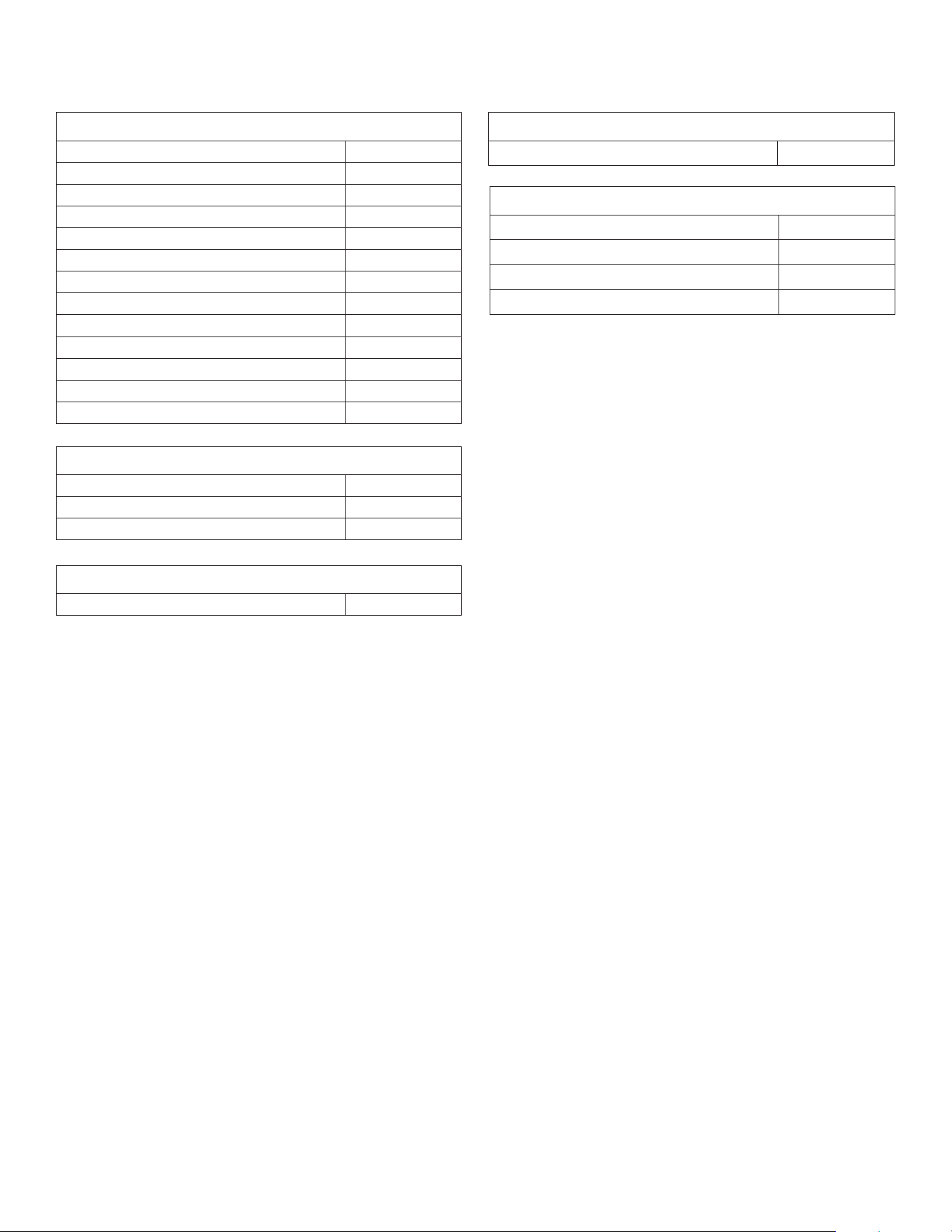
#BHM-44 R.1 August 2020 Hussong Mfg. Co., Inc. • Kozy Heat Fireplaces REPLACEMENT PARTS LIST 73
LOG SET
10 Piece Log Set BH44-500
#BH44 1 Log BH44-1
#BH44 2 Log BH44-2
#BH44 3 Log BH44-3
#BH44 4 Log BH44-4
#BH44 5 Log BH44-5
#BH44 6 Log BH44-6
#BH44 7 Log BH44-7
#BH44 8 Log BH44-8
#BH44 9 Log BH44-9
#BH44 10 Log BH44-10
1/2” Lava Rock 600-715
Rock Wool Embers 900-REMB
REFRACTORY PANEL SETS
Chicago Brick Refractory Set BH44-CB900
Ledgestone Refractory Set BH44-L900
Herringbone Refractory Set BH44-HB900
BLACK GLASS PANEL SET
Black Glass Panel Set BH44-BG900
FAN KIT
Fan Assembly BH44-028
LIGHT KITS
Ember Bed Light Kit BH44-LKT
5 lb (2.268kg) Ember Panel Crushed Glass 600-698
Top Light Kit 600-TLK
20W 120V Halogen Bulb 600-676
Hussong Manufacturing Co., Inc.
P.O. Box 577
204 Industrial Park Drive
Lakeeld, MN 56150-0577, USA
BHM-44

74 LIMITED LIFETIME WARRANTY
Hussong Mfg. Co., Inc. • Kozy Heat Fireplaces #BHM-44 R.1 August 2020
LIMITED LIFETIME WARRANTY
Warranty Coverage
Hussong Manufacturing Company, Inc. (Hussong Mfg.) warrants this
Kozy Heat gas appliance from the date of purchase to the original
purchaser, that it is free of defects in materials and workmanship at
the time of manufacture. Registering your replace warranty does not
require any documents to be sent in to Hussong Mfg. Please retain
your proof of purchase reecting the date of purchase along with the
serial number and model of your replace for any future warranty
claims.
If a defect is noted within the warranty period, the customer should
contact their authorized dealer for service within 30 days.
30 Days: Parts & Labor*
• Paint
• Light bulbs
• Gasket material
• Glass media and media dam
Year 1: Parts & Labor*
• All parts and material except the items listed in the 30 day
warranty and any exclusions or limitations that may apply.
*Hussong Mfg. will issue labor reimbursement to an authorized dealer
only. Hussong Mfg. will not be liable for charges occurred as a result of
any service performed by a non-authorized service provider, without
pre-authorization.
Years 2 through Lifetime: Parts Only
• Firebox
• Heat Exchanger
• Logs
• Burner tube or pan
• Outer shell
• Heat shield(s)
• Front Viewing Glass (thermal shock only)
• Refractory Firebox liner (excluding enamel and glass panels)
EXCLUSIONS AND LIMITATIONS
1. This appliance must be installed by a licensed, authorized service technician or contractor. It must be installed, operated and maintained
at all times in accordance with the instructions in the owner’s manual or the warranty is void.
2. This warranty is nontransferable and is made to the original purchaser only.
3. This warranty excludes standard wear and tear of the appliance which is considered normal usage over time.
4. Discoloration and some minor expansion, contraction or movement of certain parts, resulting in noise, is normal and not a defect.
5. Warranty is automatically voided if the appliance’s serial number and/or testing label is removed or if the appliance is altered or
tampered with in any way.
6. Warranty is void if the appliance is subject to submersion in water or prolonged periods of dampness or condensation. Any damage
to any part of the appliance due to water or weather damage which is the result of, but not limited to, improper chimney/venting
installation will also render this warranty void.
7. This warranty does not cover installation and operational related problems such as environmental conditions, nearby trees, buildings,
hilltops, mountains, inadequate venting or ventilation, excessive osets, negative air pressures caused by any mechanical systems.
8. Chimney components and other Non-Hussong Mfg. accessories used in conjunction with the installation of this appliance are not
covered under this warranty.
9. Damage to plated surfaces or accessories, if applicable, caused by scratches, ngerprints, melted items or other external sources left on
the surfaces from the use of cleaners is not covered under this warranty.
10. It is expressly agreed and understood that this warranty is Hussong Mfg.’s sole obligation and purchaser’s exclusive remedy for defective
replace equipment. Hussong Mfg. is free of liability for any damages caused by this appliance, as well as inconvenience expenses
and materials. Incidental or consequential damages are not covered by this warranty. In some states, the exclusion of incidental or
consequential damage may not apply. Hussong Mfg. shall not be held to implied warranties and this warranty shall replace all previous
warranties.
11. This limited lifetime warranty is the only warranty supplied by Hussong Mfg. Any warranties extended to the purchaser by the dealer/
distributor, whether expressed or implied, are hereby disclaimed and the purchaser’s recourse is expressly limited to the warranties set
forth herein.
12. Any part repaired or replaced during the limited warranty period will be warranted under the terms of the limited warranty for a period
not to exceed the remaining term of the original limited warranty.
13. Any replacement part repaired after the warranty period will include a 90 day parts coverage
14. Hussong Mfg. may require the defective part to be returned using a pre-authorized RGA number or a photo of the defective component.
Failure to provide either can result in a denied claim.
15. This warranty does not cover the appliances ability to heat a desired space, as there are many factors that can impact the heating
performance in each home. Consideration should be implied to the appliance’s location, room size, home design, environmental
conditions, insulation, and tightness of the home.
16. Hussong Mfg. reserves the right to make changes at any time, without notice, in design, material, specications, and prices. Hussong
Mfg. reserves the right to discontinue models and products.
July 2018