Read and understand this entire owner’s manual, including all safety
information, before plugging in or using this product. Failure to do so
could result in fire, electric shock, or serious personal injury. Don’t
spray water directly on to product. Clean with damp cloth or duster.
Keep this owner’s manual for future reference. If you sell or give this
product away, make sure this manual accompanies this product.
WARNING
CAUTION
Approved for Indoor and Outdoor Use
Rated: 220~240VAC 50/60Hz 6,800 BTUS
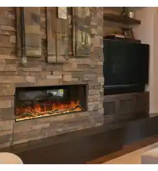
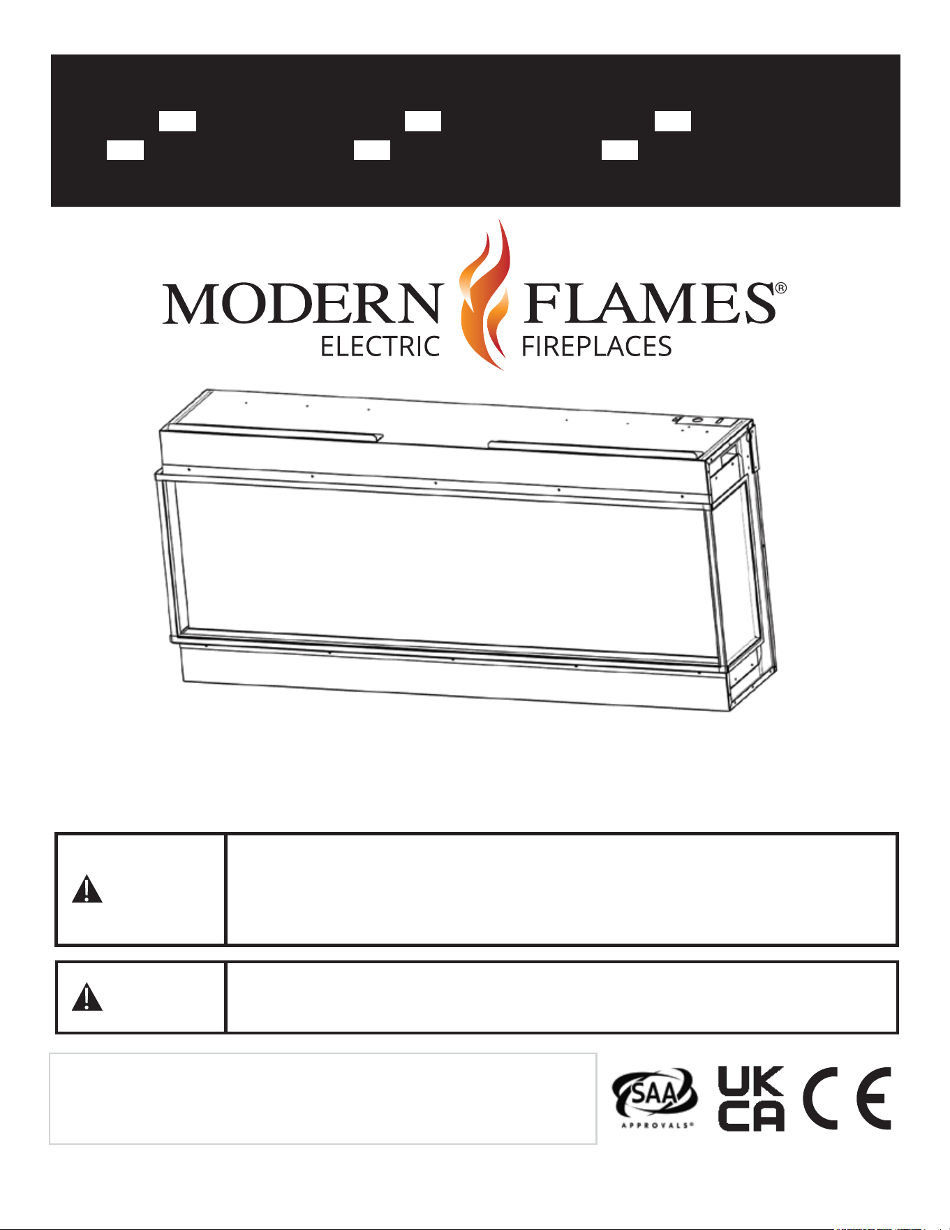
Landscape Pro Multi Electric Fireplace
Model# LPM-4416V2/INT LPM-5616V2/INT LPM-6816V2/INT
LPM-8016V2/INT LPM-9616V2/INT LPM-12016V2/INT
Installation Manual
AFFIX SERIAL NUMBER LABEL
HERE FOR FUTURE REFERENCE
07-00011-1 REV C
IMPORTANT SAFETY INFORMATION!
WARNING
When using electrical appliances, basic precautions should always be followed to reduce the risk of
fire, electric shock, and injury to persons, including the following:
1. Read all Instructions before installing or using the heater.
2. This heater is hot when in use. To avoid burns, do not let bare skin touch hot surfaces.
Keep combustible materials, such as furniture, pillows, bedding, papers, clothes, etc. and curtains
at l east 3 feet (0.9 m) from the front of the heater and keep them away from the sides and rear
(sides and rear restrictions apply to location dedicated heaters only)
3. Extreme caution is necessary when any heater is used by or near children or invalids and
whenever the heater is left operating and unattended.
4. Do not operate heater after it malfunctions. Disconnect power at service panel and have the
heater inspected by a reputable electrician before reusing.
5. To disconnect heater, turn controls to off, and turn power to heater circuit at main disconnect
panel (or operate internal disconnect switch if provided).
6. Do not insert or allow foreign objects to enter any ventilation or exhaust opening as this may
cause an electric shock or fire, or damage the heater.
7. To prevent a possible fire, do not block air intakes or exhaust in any manner.
8. A heater has hot and arcing or sparking parts inside. Do not use if in areas where gasoline, paint,
or flammable vapors or liquids are used or stored.
9. Use this heater only as described in this manual. Any other use not recommended by the
manufacturer may cause fire, electric shock, or injury to persons.
10. This heater may include an audible or visual alarm to warn that parts of the heater are getting
excessively hot. If the alarm sounds (or illuminates), immediately turn the heater off and inspect
for any objects on or adjacent to the heater that may have blocked the airflow or otherwise
caused high temperature to have occurred. DO NOT OPERATE THE HEATER WITH THE ALARM
SOUNDING (OR ILLUMINATING).
11.
“SAVE THESE INSTRUCTIONS”
Additional Important Instructions
• Use a dedicated 13 Amp (EU) or 10 Amp (AU/NZ) (or higher) breaker.
• Never use with an extension cord or relocatable power tap (outlet/power strip).
• Never use a wall mount bracket from another manufacturer.
• Always disconnect this unit from the power supply before performing any assembly or
cleaning, or before relocating the electric fireplace.
• Always store this heater in a dry location.
• This product is not intended to be a primary heat source. It is for supplemental heat only.
• Outdoor installations other as defined in the manual void warranty.
1
IMPORTANT INSTRUCTIONS
ATTENTION
When using electrical appliances, basic precautions should always be followed to reduce the risk of fire,
electric shock, and injury to persons, including the following:
1. Read all Instructions before installing or using the heater.
2. This heater is hot when in use. To avoid burns, do not let bare skin touch hot surfaces. Keep combustible
materials, such as furniture, pillows, bedding, papers, clothes, etc. and curtains at least 3 feet (0.9 m)
from the front of the heater and keep them away from the sides and rear (sides and rear restrictions
apply to location dedicated heaters only)
3. Extreme caution is necessary when any heater is used by or near children or invalids and whenever the
heater is left operating and unattended.
4. Do not operate heater after it malfunctions. Disconnect power at service panel and have the heater
inspected by a reputable electrician before reusing.
5. To disconnect heater, turn controls to off, and turn power to heater circuit at main disconnect panel (or
operate internal disconnect switch if provided).
6. Do not insert or allow foreign objects to enter any ventilation or exhaust opening as this may cause an
electric shock or fire, or damage the heater.
7. To prevent a possible fire, do not block air intakes or exhaust in any manner.
8. A heater has hot and arcing or sparking parts inside. Do not use if in areas where gasoline, paint, or
flammable vapors or liquids are used or stored.
9. Use this heater only as described in this manual. Any other use not recommended by the manufacturer
may cause fire, electric shock, or injury to persons.
10. This heater may include an audible or visual alarm to warn that parts of the heater are getting
excessively hot. If the alarm sounds (or illuminates), immediately turn the heater off and inspect for any
objects on or adjacent to the heater that may have blocked the airflow or otherwise caused high
temperature to have occurred. DO NOT OPERATE THE HEATER WITH THE ALARM SOUNDING (OR
ILLUMINATING).
12.
“SAVE THESE INSTRUCTIONS”
Additional Important Instructions
• Use a dedicated circuit breaker of 13 A (EU) or A (AU/NZ) (or more).
• Never use with an extension cord or relocatable power tap (outlet/power strip).
• Never use a wall mount bracket from another manufacturer.
• Always disconnect this unit from the power supply before performing any assembly or cleaning, or
before relocating the electric fireplace.
• Always store this heater in a dry location. Never use the fireplace if it has become wet.
• This product is not intended to be a primary heat source. It is for supplemental heat only.
2

USER INSTRUCTIONS
POWER DATA
LPM-4414V2/INT LPM-5614V2/INT LPM-6814V2/INT LPM-8014V2/INT LPM-9614V2/INT LPM-12014V2/INT
Volts/HZ Amps AC 220~240V AC 220~240V AC 220~240V AC 220~240V AC 220~240V AC 220~240V
50/60Hz 9 Amps 50/60Hz 9 Amps 50/60Hz 9 Amps 50/60Hz 9 Amps 50/60Hz 9 Amps 50/60Hz 9 Amps
Heater AC 220~240V AC 220~240V AC 220~240V AC 220~240V AC 220~240V AC 220~240V
2000W 2000W 2000W 2000W 2000W 2000W
BTUs 6,800 BTUs 6,800 BTUs 6,800 BTUs 6,800 BTUs 6,800 BTUs 6,800 BTUs
Lamps LED 12V LED 12V LED 12V LED 12V LED 12V LED 12V
Motor 12 VDC 12 VDC 12 VDC 12 VDC 12 VDC 12 VDC
Stepper Motor Stepper Motor Stepper Motor Stepper Motor Stepper Motor Stepper Motor
Shipping Size
47.25" x 28.5" 59" x 28.5" 71" x 28.5" 83" x 28.5" 99" x 28.5" 123" x 28.5"
x 14.5" x 14.5" x 14.5" x 14.5" x 14.5" x 14.5"
1200 mm
x 720 mm
x 370 mm
1500 mm
x 720 mm
x 370 mm
1800 mm
x 720 mm
x 370 mm
2105 mm
x 720 mm
x 370 mm
2510 mm
x 720 mm
x 370 mm
3120 mm
x 720 mm
x 370 mm
3
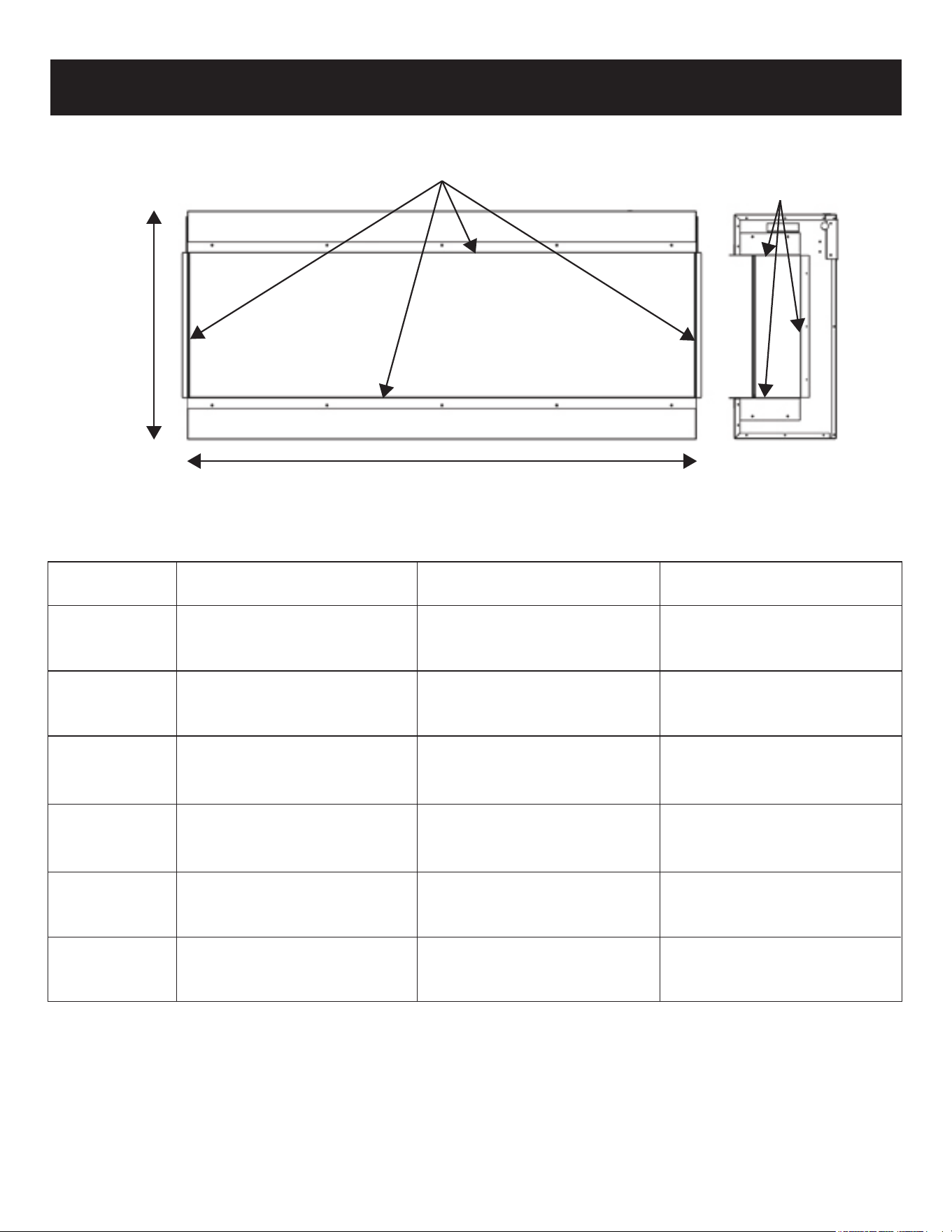
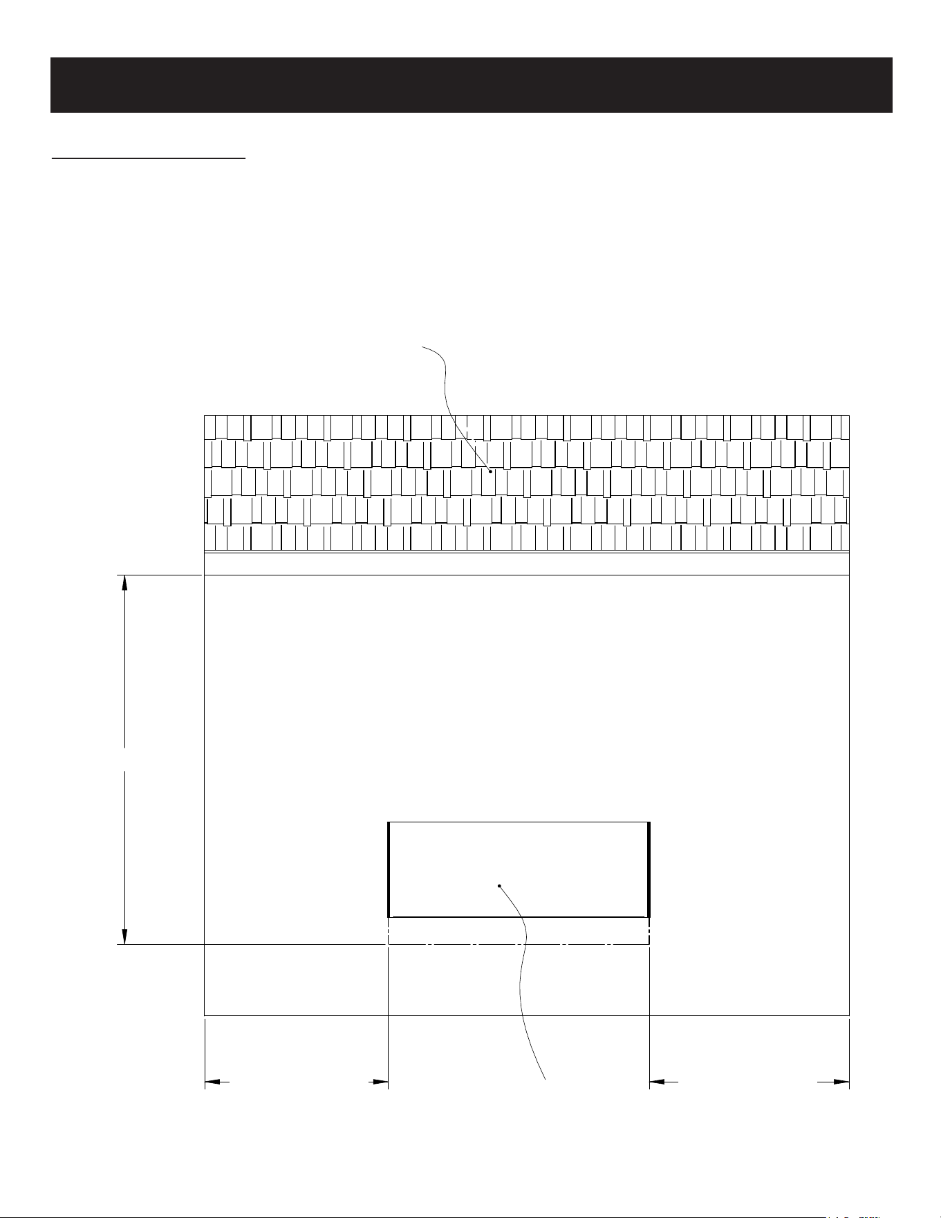
294mm
(all models)
11 9/16”
632mm
(all models)
24 7/8”
DRYWALL STOPS
DRYWALL
STOPS
Width varies (see chart below)
Model Viewing Area Firebox Dimensions Framing Dimensions
LPM-4416V2/INT
1099 mm W x 403 mm H x 135 mm D 1120 mm W x 632 mm H x 294 mm D 1128 mm W x 642 mm H x 305 mm D
43 1/4" W x 15 7/8" H x 5 5/16" D 44 1/16" W x 24 7/8" H x 11 9/16" D 44 3/8" W x 25 1/4" H x 12" D
LPM-5616V2/INT
1403 mm W x 403 mm H x 135 mm D 1424 mm W x 632 mm H x 294 mm D 1432 mm W x 642 mm H x 305 mm D
55 1/4" W x 15 7/8" H x 5 5/16" D 56 1/16" W x 24 7/8" H x 11 9/16" D 56 3/8" W x 25 1/4" H x 12" D
LPM-6816V2/INT
1708 mm W x 403 mm H x 135 mm D 1729 mm W x 632 mm H x 294 mm D 1737 mm W x 642 mm H x 305 mm D
67 1/4" W x 15 7/8" H x 5 5/16" D 68 1/16" W x 24 7/8" H x 11 9/16" D 68 3/8" W x 25 1/4" H x 12" D
LPM-8016V2/INT
2013 mm W x 403 mm H x 135 mm D 2034 mm W x 632 mm H x 294 mm D 2042 mm W x 642 mm H x 305 mm D
79 1/4" W x 15 7/8" H x 5 5/16" D 80 1/16" W x 24 7/8" H x 11 9/16" D 80 3/8" W x 25 1/4" H x 12" D
LPM-9616V2/INT
2419 mm W x 403 mm H x 135 mm D 2440 mm W x 632 mm H x 294 mm D 2448 mm W x 642 mm H x 305 mm D
95 1/4" W x 15 7/8" H x 5 5/16" D 96 1/16" W x 24 7/8" H x 11 9/16" D 96 3/8" W x 25 1/4" H x 12" D
LPM-12016V2/INT
3029 mm W x 403 mm H x 135 mm D 3050 mm W x 632 mm H x 294 mm D 3058 mm W x 642 mm H x 305 mm D
119 1/4" W x 15 7/8" H x 5 5/16" D 120 1/16" W x 24 7/8" H x 11 9/16" D 120 3/8" W x 25 1/4" H x 12" D
PRODUCT GUIDE
4
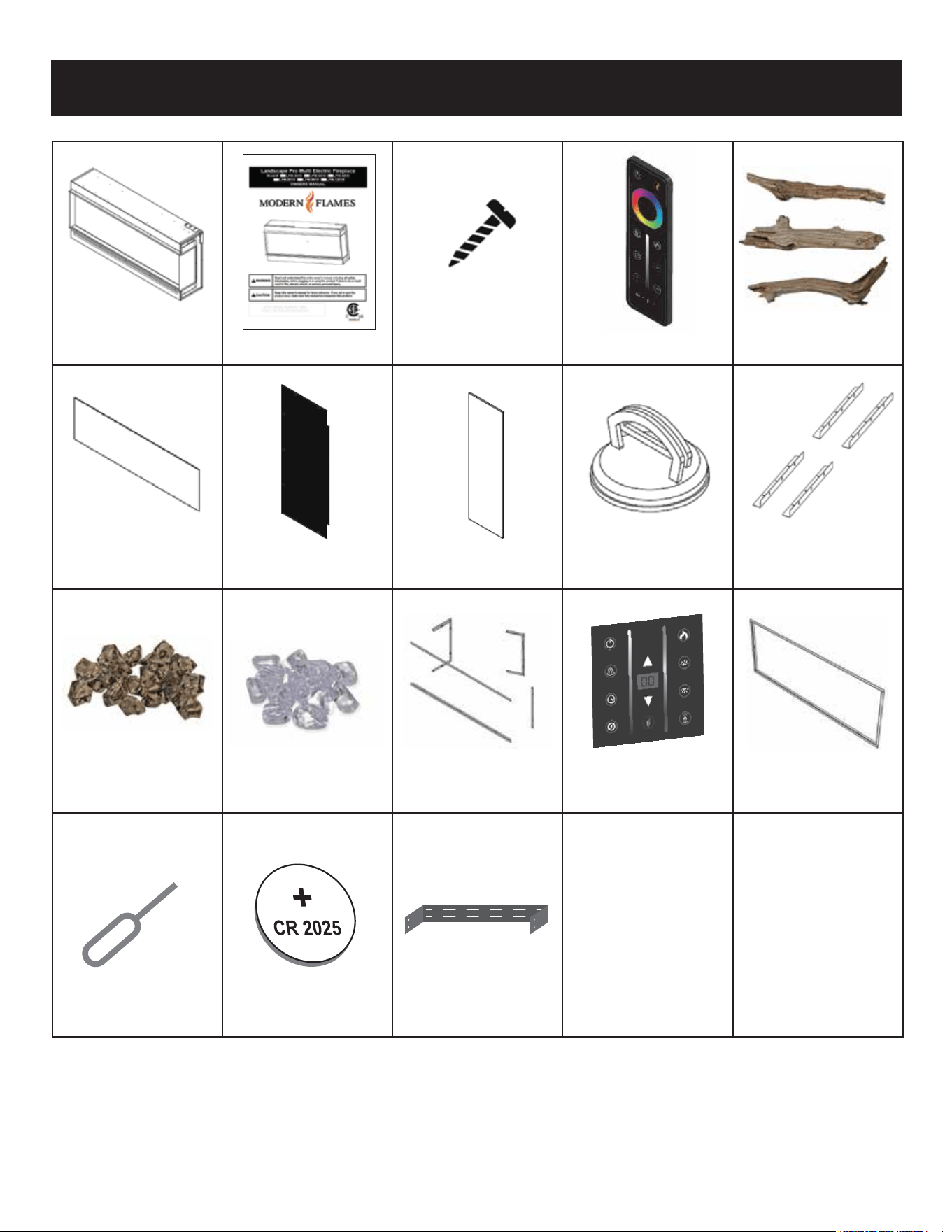
PARTS AND HARDWARE
Bracket (1) Canyon
(1) Fireplace (1) Owners Manual (6) Screws (1) Remote Driftwood Logs Set
(2-4) L-Metal
(Depend on Model)
(1) Front Glass (2) Metal Side Panels (2) Side Glass (2) Suction Cups Mounting Brackets
(1) Wall Mount
Smoke Clear
(1) 5-Piece Trim Kit Touch Control
Acrylic Crystals Pkg Acrylic Stones Pkg
(Sold Separately)
(Sold Separately)
(1) 1 Piece Trim Kit
(1) Wall Mount Bracket
Battery Tool (1) CR2025 Battery (Kit Sold Separately)
5
INSTALLATION
Select a suitable location that is away from drapes, furniture, and high traffic areas.
NOTE: Follow all National and local electrical codes.
Due to the many different materials used on different walls, it is highly recommended that
you consult your local builder before you install this fireplace.
Remove all parts and hardware from the carton and place them on a clean, soft, dry surface.
Parts and assembly steps are grouped for use. Check the parts list to make sure nothing is
missing. Dispose of packaging materials properly. Please recycle whenever possible.
You will need the following tools (not included): Phillips screwdriver, stud finder, level,
tape measure, electric drill, 1/4" wood drill bit, hammer.
This product includes a GLASS panel. Always use extreme caution when handling
glass. Failure to do so could result in personal injury or property damage.
6
A
B
C
D
7
7
6
6
5
5
4
4
3
3
2
2
1
1
NOT SPECIFIED
DO NOT SCALE DRAWING
UST120_A1_20221031
SHEET 1 OF 1
UNLESS OTHERWISE SPECIFIED:
SCALE: 1:10
WEIGHT:
REV
DWG. NO.
D
SIZE
TITLE:
NAME
DATE
COMMENTS:
Q.A.
MFG APPR.
ENG APPR.
CHECKED
DRAWN
FINISH
MATERIAL
INTERPRET GEOMETRIC
TOLERANCING PER:
DIMENSIONS ARE IN INCHES
TOLERANCES:
FRACTIONAL
ANGULAR: MACH
BEND
TWO PLACE DECIMAL
THREE PLACE DECIMAL
APPLICATION
USED ON
NEXT ASSY
PROPRIETARY AND CONFIDENTIAL
THE INFORMATION CONTAINED IN THIS
DRAWING IS THE SOLE PROPERTY OF
<INSERT COMPANY NAME HERE>. ANY
REPRODUCTION IN PART OR AS A WHOLE
WITHOUT THE WRITTEN PERMISSION OF
<INSERT COMPANY NAME HERE> IS
PROHIBITED.
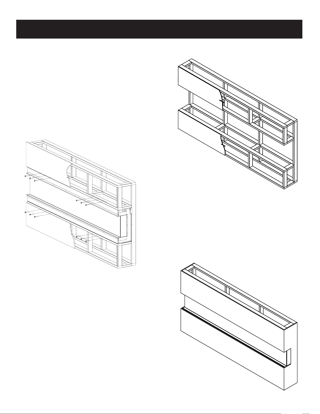
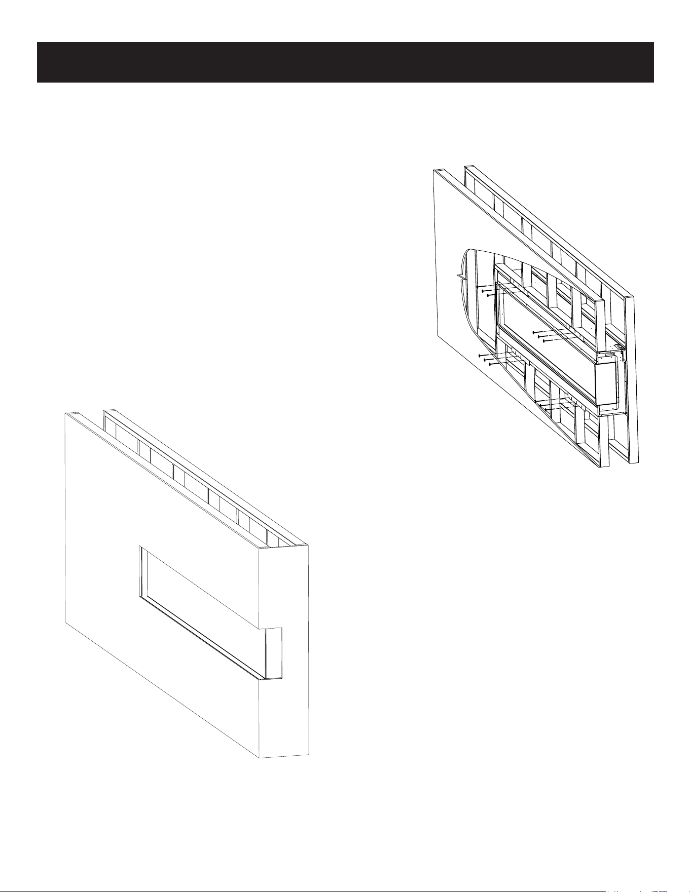
BUILT-IN INSTALLATION
3 Sided Installation (Bay)
2. Install L Metal mounting brackets to
the top and bottom of the fireplace
with supplied screws.
3. Hardwire fireplace (see page 16)
4. Install the fireplace in the framed
opening with a minimum 1 1/4" 32 mm
drywall screws to secure the unit.
1. Prepare the framed opening according
to the chart on page 4.
*Provide appropriate dedicated circuit
for hardwire install at the top right of
framed opening.
5. Mask the exposed fireplace during the drywall
process. Install drywall to the drywall stops on
the perimeter of the fire box. For more
information on the drywall stops see the
Product Guide on page 4.
6. Decorate according to media installation guide
on page 13.
7. Install the side and front glass pieces according
to installation diagram on Page 15.
8. Install optional 5-pc. trim kit (sold separately.)
7
A
B
4
4
3
3
2
2
DO NOT SCALE DRAWING
UNLESS OTHERWISE SPECIFIED:
FINISH
MATERIAL
INTERPRET GEOMETRIC
TOLERANCING PER:
DIMENSIONS ARE IN INCHES
TOLERANCES:
FRACTIONAL
ANGULAR: MACH
BEND
TWO PLACE DECIMAL
THREE PLACE DECIMAL
APPLICATION
USED ON
NEXT ASSY
PROPRIETARY AND CONFIDENTIAL
THE INFORMATION CONTAINED IN THIS
DRAWING IS THE SOLE PROPERTY OF
<INSERT COMPANY NAME HERE>. ANY
REPRODUCTION IN PART OR AS A WHOLE
WITHOUT THE WRITTEN PERMISSION OF
<INSERT COMPANY NAME HERE> IS
PROHIBITED.
A
B
C
D
7
7
6
6
5
5
4
4
3
3
2
2
1
1
NOT SPECIFIED
DO NOT SCALE DRAWING
UST120_A1_20221031-Two sides
SHEET 1 OF 1
UNLESS OTHERWISE SPECIFIED:
SCALE: 1:20
WEIGHT:
REV
DWG. NO.
D
SIZE
TITLE:
NAME
DATE
COMMENTS:
Q.A.
MFG APPR.
ENG APPR.
CHECKED
DRAWN
FINISH
MATERIAL
INTERPRET GEOMETRIC
TOLERANCING PER:
DIMENSIONS ARE IN INCHES
TOLERANCES:
FRACTIONAL
ANGULAR: MACH
BEND
TWO PLACE DECIMAL
THREE PLACE DECIMAL
APPLICATION
USED ON
NEXT ASSY
PROPRIETARY AND CONFIDENTIAL
THE INFORMATION CONTAINED IN THIS
DRAWING IS THE SOLE PROPERTY OF
<INSERT COMPANY NAME HERE>. ANY
REPRODUCTION IN PART OR AS A WHOLE
WITHOUT THE WRITTEN PERMISSION OF
<INSERT COMPANY NAME HERE> IS
PROHIBITED.
A
B
C
D
8 7
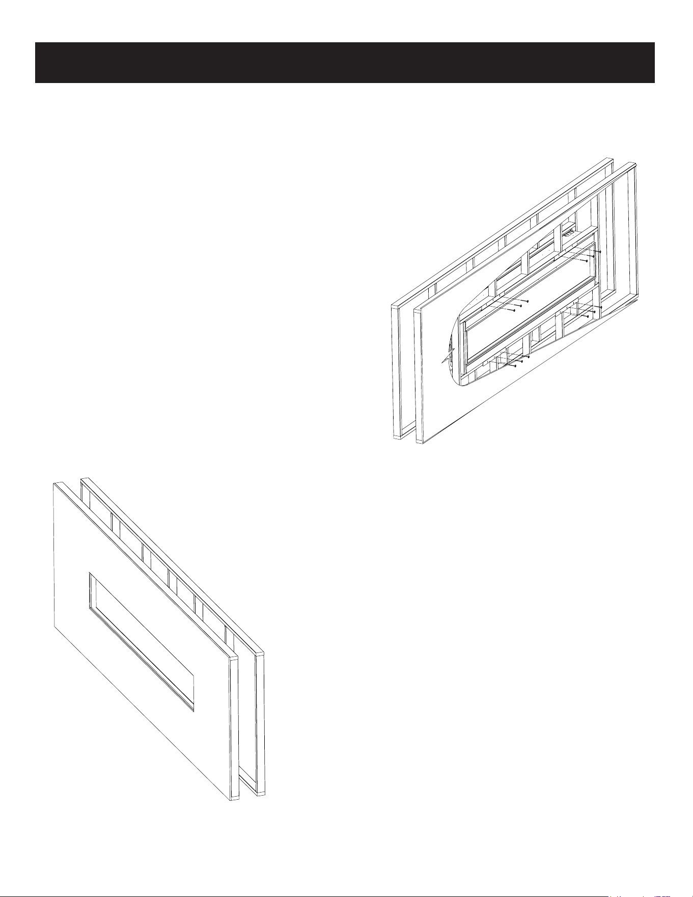
BUILT-IN INSTALLATION
Fully Recessed Installation
(Left/Right Corner)
1. Follow steps from the 3-sided installation
instructions.
2. Remove the corresponding drywall stops according
to your installation (in the example, the drywall
stops on the left end would be removed.)
3. Install the side glass then the corresponding side
cover according to your installation (the side glass
must be installed before the metal side cover.
See installation diagram on Page 15.)
4. Wire fireplace (see page 3) for maximum
heating power (10,000 BTUs) see page 15
for optional wiring
5. Install the fireplace in the framed opening
with a minimum 1 1/4" 32mm drywall
screws to secure the unit.
6. Mask the exposed fireplace during the
drywall process. Install drywall to the
drywall stops on the perimeter of the
fireplace. For more information on the
drywall stops see the Product Guide on
page 4.
7. Decorate according to media installation
guide on page 13.
8. Install the remaining side glass and front
glass according to installation diagram on
Page 16.
9. Install optional 5-pc. trim kit (sold separately.)
8
A
B
1
1
NOT SPECIFIED
UST120_A1_20221031
SHEET 1 OF 1
SCALE: 1:33.3
WEIGHT:
REV
DWG. NO.
B
SIZE
TITLE:
NAME
DATE
A
B
C
D
8
8
7
7
6
6
5
5
4
4
A
B
C
D
6 5 4 3 2 1
NOT SPECIFIED
UST120_A1_20221031
UNLESS OTHERWISE SPECIFIED:
REV
DWG. NO.
D
SIZE
TITLE:
NAME
DATE
COMMENTS:
Q.A.
MFG APPR.
ENG APPR.
CHECKED
DRAWN
FINISH
MATERIAL
INTERPRET GEOMETRIC
TOLERANCING PER:
DIMENSIONS ARE IN INCHES
TOLERANCES:
FRACTIONAL
ANGULAR: MACH
BEND
TWO PLACE DECIMAL
THREE PLACE DECIMAL
USED ON
NEXT ASSY
PROPRIETARY AND CONFIDENTIAL
THE INFORMATION CONTAINED IN THIS
DRAWING IS THE SOLE PROPERTY OF
<INSERT COMPANY NAME HERE>. ANY
REPRODUCTION IN PART OR AS A WHOLE
WITHOUT THE WRITTEN PERMISSION OF
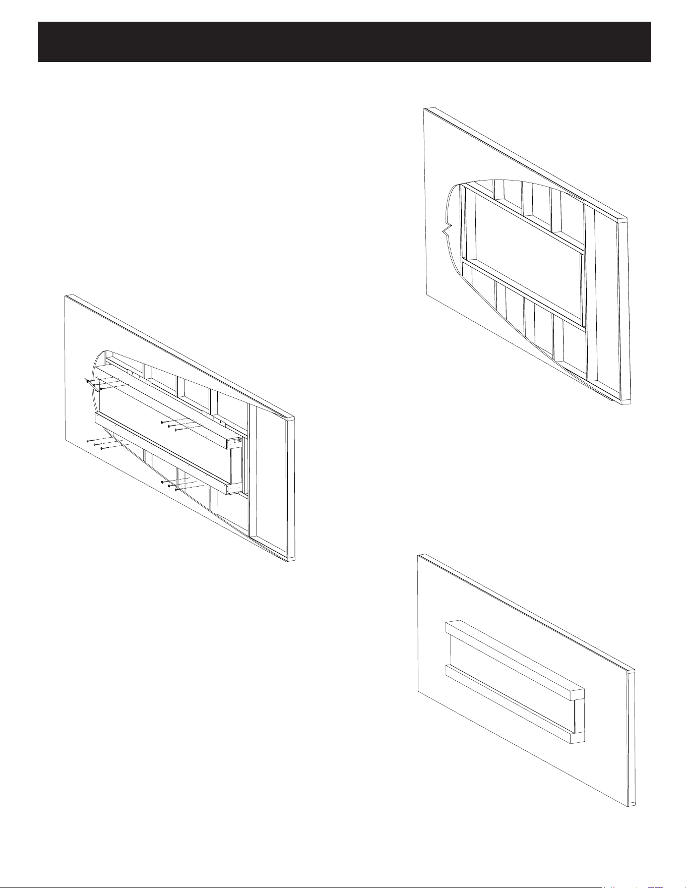
BUILT-IN INSTALLATION
Fully Recessed Installation (Single Sided)
1. Follow steps from the 3 sided installation
instructions.
2. Remove the drywall stops on both sides of the
fire unit.
3. Install the side glass then side covers on both
sides of the fire unit (the side glass must be
installed before the metal side cover. See
installation diagram on Page 15.)
4. Install the fire unit in the framed opening with
a minimum 1 1/4" 32 mm drywall screws to
secure the unit.
5. Mask the exposed fireplace during the drywall
process. Install drywall to the drywall stops on the
perimeter of the fireplace. For more information on
the drywall stops see the Product Guide on page 3.
6. Decorate according to media installation guide on
page 13.
7. Install the front glass according to installation
diagram on Page 15.
8. Installation optional: 1-pc trim kit (included.)
9
A
B
C
D
6
6
5
5
4
4
3
3
2
2
1
1
NOT SPECIFIED
DO NOT SCALE DRAWING
UST120_A1_20221031
SHEET 1 OF 1
UNLESS OTHERWISE SPECIFIED:
SCALE: 1:20
WEIGHT:
REV
DWG. NO.
D
SIZE
TITLE:
NAME
DATE
COMMENTS:
Q.A.
MFG APPR.
ENG APPR.
CHECKED
DRAWN
FINISH
MATERIAL
INTERPRET GEOMETRIC
TOLERANCING PER:
DIMENSIONS ARE IN INCHES
TOLERANCES:
FRACTIONAL
ANGULAR: MACH
BEND
TWO PLACE DECIMAL
THREE PLACE DECIMAL
APPLICATION
USED ON
NEXT ASSY
PROPRIETARY AND CONFIDENTIAL
THE INFORMATION CONTAINED IN THIS
DRAWING IS THE SOLE PROPERTY OF
<INSERT COMPANY NAME HERE>. ANY
REPRODUCTION IN PART OR AS A WHOLE
WITHOUT THE WRITTEN PERMISSION OF
<INSERT COMPANY NAME HERE> IS
PROHIBITED.
BUILT-IN INSTALLATION
Half Recessed Installation
1. This installation is optimized for a 2x4 framed wall.
Prepare the framed opening according to the height
and width of the chart on page 4.
*Provide appropriate dedicated circuit for hardwire
install at the top right of framed opening.
2. Install L Metal Nailing Flanges to the top
and bottom of the fireplace.
3. Hardwire fireplace (see page 16)
4. Install the fire unit in the framed opening
with a minimum 1 1/4" 32 mm drywall
screws to secure the unit.
5. Mask the exposed viewing area of fireplace
during this process. Install drywall, tile or
material of your choice to the drywall stops
on the perimeter of the fireplace. For more
information on the drywall stops see the
Product Guide on page 4.
6. Decorate according to media installation
guide on page 13.
7. Install the side and front glass pieces
according to installation diagram on Page 15.
8. Finish fireplace with your desired decorative.
A
B
C
D
8
8
7
7
6
6
5
5
4
4
3
3
THE INFORMATION CONTAINED IN THIS
DRAWING IS THE SOLE PROPERTY OF
<INSERT COMPANY NAME HERE>. ANY
REPRODUCTION IN PART OR AS A WHOLE
WITHOUT THE WRITTEN PERMISSION OF
<INSERT COMPANY NAME HERE> IS
PROHIBITED.
A
B
C
D
8 7 6 5 4
10
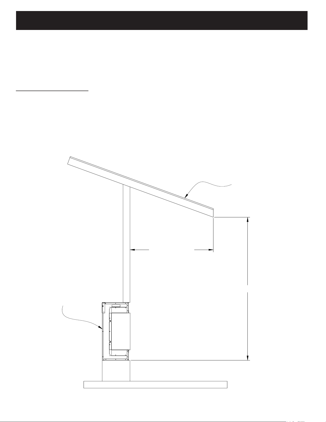
OUTDOOR INSTALLATION REQUIREMENTS
The LPM Series electric fireplaces from Modern Flames LLC have been tested and approved for
installation outdoors under a patio cover and away from direct water contact or direct sun light.
Modern Flames LLC standard warranty applies if installed per instructions. All electrical wiring
shall be to local building codes. Consult professional installers before installation. Approved
installations are as noted below.
A
B
C
D
2
2
1
1
DO NOT SCALE DRAWING
Recessed Fireplace Wall_Bay_G
SHEET 1 OF 1
UNLESS OTHERWISE SPECIFIED:
SCALE: 1:20
WEIGHT:
REV
DWG. NO.
D
SIZE
TITLE:
NAME
DATE
COMMENTS:
Q.A.
MFG APPR.
ENG APPR.
CHECKED
DRAWN
FINISH
MATERIAL
INTERPRET GEOMETRIC
TOLERANCING PER:
DIMENSIONS ARE IN INCHES
TOLERANCES:
FRACTIONAL
ANGULAR: MACH
BEND
TWO PLACE DECIMAL
THREE PLACE DECIMAL
APPLICATION
USED ON
A
B
C
D
2 1
UNLESS OTHERWISE SPECIFIED:
TITLE:
NAME
DATE
DRAWN
DIMENSIONS ARE IN INCHES
TOLERANCES:
Front Protection:
Patio roof overhang must be 50% (or more) of the height of the patio roof from bottom
of fireplace.
If: H=6’
Then: OD=3’ minimum (6’ x 50%=3’)
Note 1: Base of fireplace must be 2" (minimum) above floor.
Note 2: H taken from bottom of fireplace.
HEIGHT (H)
OVERHANG
DISTANCE (OD)
OVERHANG
LPM
4 3 2
11
OUTDOOR INSTALLATION REQUIREMENTS
Side Protection:
Side distance (SD) must be 50% (or more) of the height(H).
12
If: H=6’
Then: SD=3’ minimum (6’ x 50%=3’)
Note: H taken from bottom of fireplace.
HEIGHT (H)
SIDE DISTANCE
(SD)
SIDE DISTANCE
(SD)
LPM
OVERHANG
4 3 2
BUILT-IN INSTALLATION
Suite Wall Mount &
Recessed Cabinet Installation
Follow the directions included with the
Suite Wall Mount Accessory Kit.
1. Before installing the front glass, evenly spread out
the acrylic crystals along the ember bed.
2. Place the logs on top of the acrylic crystals.
3. The front glass can now be installed.
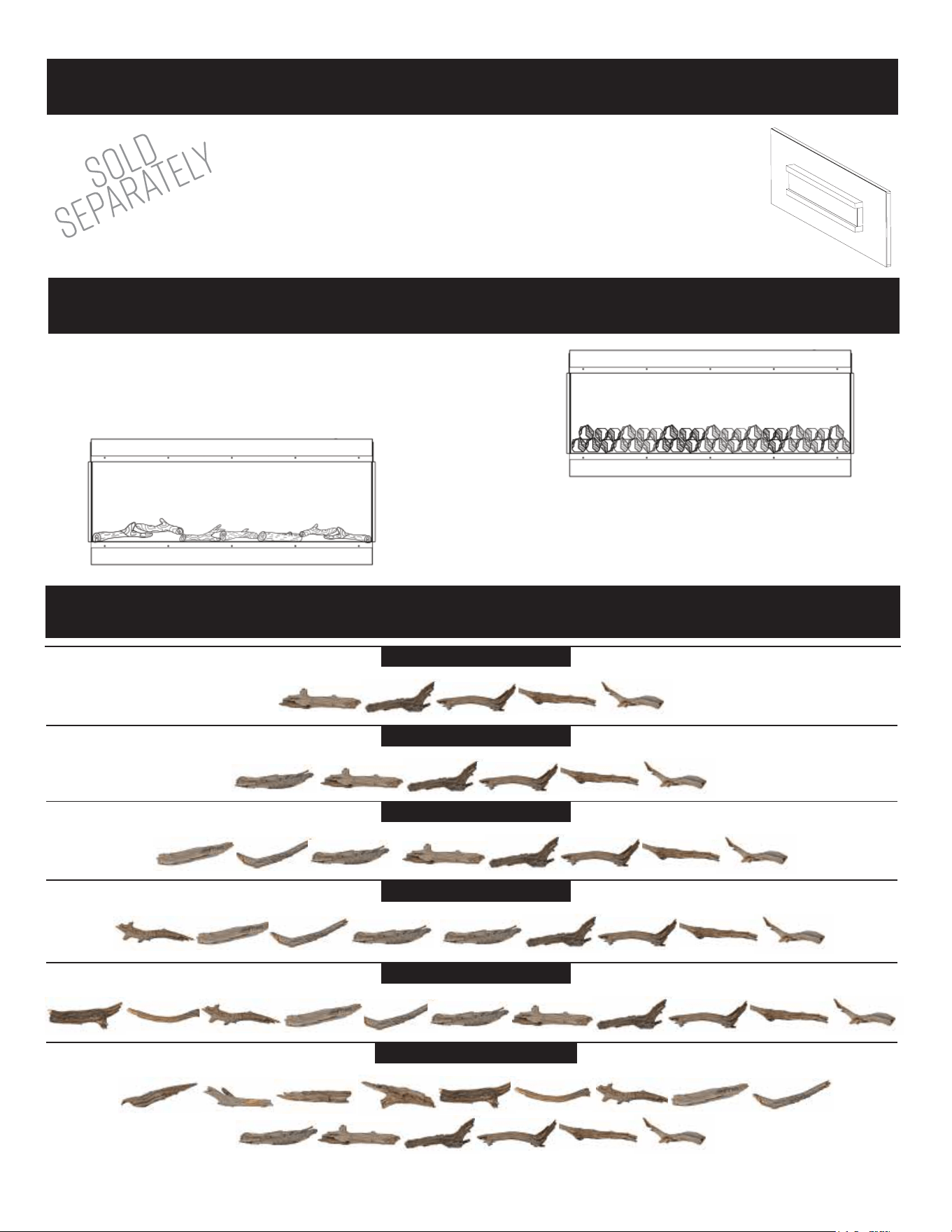
INSTALLING MEDIA
LANDSCAPE PRO MULTI - LOG SET SIZES
44" - 56" - 68" - 80" - 96" - 120"
#1 LOG#2 LOG#3 LOG#4 LOG#5 LOG
LPM 44" - Set contains 5 logs
#1 LOG#2 LOG#3 LOG#4 LOG#5 LOG
LPM 56" - Set contains 6 logs
#1 LOG#2 LOG#3 LOG#4 LOG#5 LOG
LPM 68" - Set contains 8 logs
#6 LOG#7 LOG#8 LOG#9 LOG
LPM 80" - Set contains 9 logs
#7 LOG#8 LOG#9 LOG#10 LOG#11 LOG
LPM 96" - Set contains 11 logs
#11 LOG#12 LOG#13 LOG#14 LOG#15 LOG
LPM 120" - Set contains 15 logs
#7 LOG#8 LOG#9 LOG#10 LOG
#1 LOG#2 LOG#3 LOG#4 LOG#5 LOG#6 LOG
#6 LOG
#6 LOG#7 LOG#8 LOG
#1 LOG#2 LOG#3 LOG#4 LOG#5 LOG
#6 LOG #1 LOG#2 LOG#3 LOG#4 LOG#5 LOG
A
B
C
D
1
A
B
C
D
8
8
7
7
6
6
5
5
4
4
3
3
PROPRIETARY AND CONFIDENTIAL
THE INFORMATION CONTAINED IN THIS
DRAWING IS THE SOLE PROPERTY OF
<INSERT COMPANY NAME HERE>. ANY
REPRODUCTION IN PART OR AS A WHOLE
WITHOUT THE WRITTEN PERMISSION OF
<INSERT COMPANY NAME HERE> IS
PROHIBITED.
13
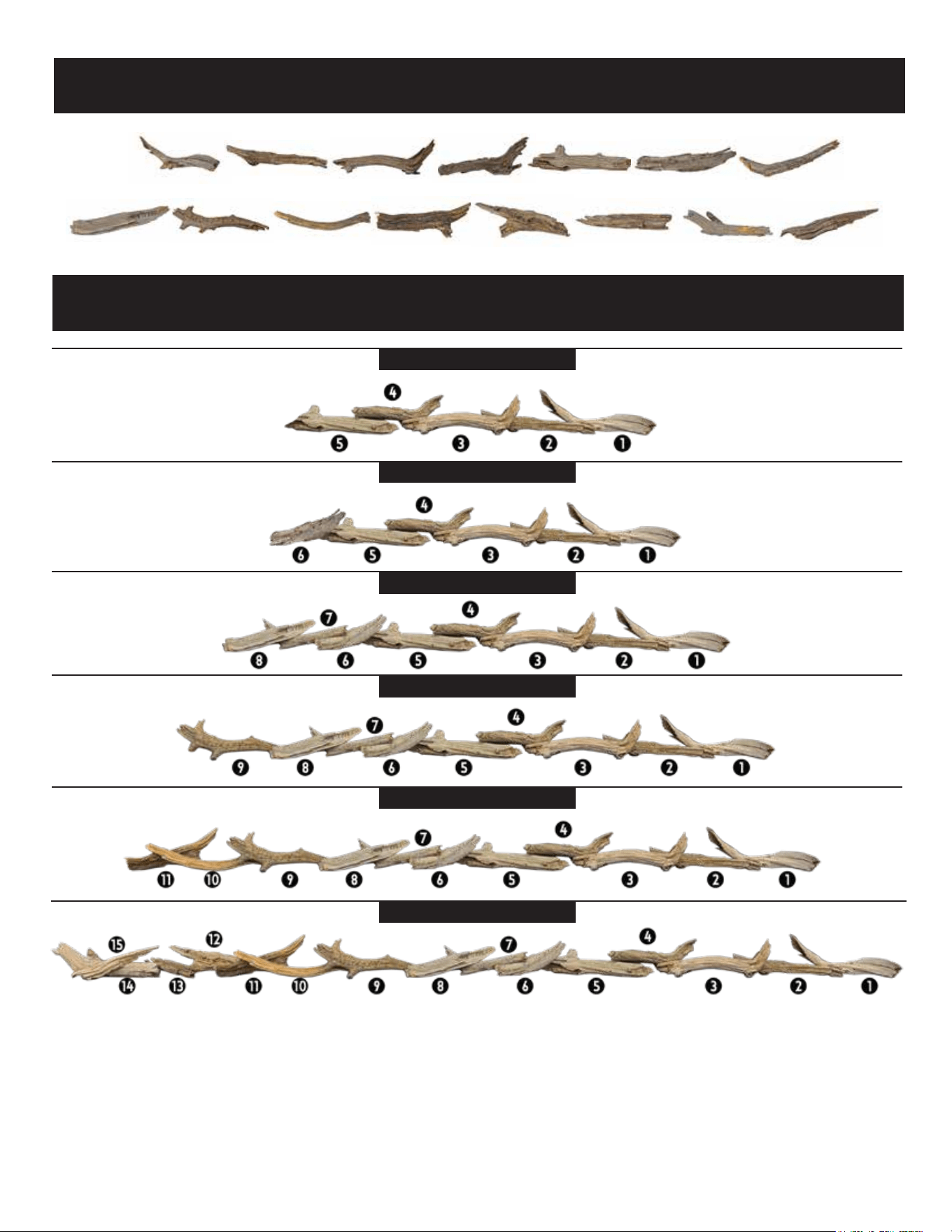
LPM 44" - Log Placement
LPM 120" - Log Placement
LPM 56" - Log Placement
LPM 68" - Log Placement
LPM 80" - Log Placement
LPM 96" - Log Placement
LOG PLACEMENT
LANDSCAPE PRO MULTI - LOG PLACEMENT
44" - 56" - 68" - 80" - 96" - 120"
#8 LOG #9 LOG #10 LOG #11 LOG #12 LOG #13 LOG #14 LOG
#15 LOG
#1 LOG #2 LOG #3 LOG #4 LOG #5 LOG #6 LOG #7 LOG
14
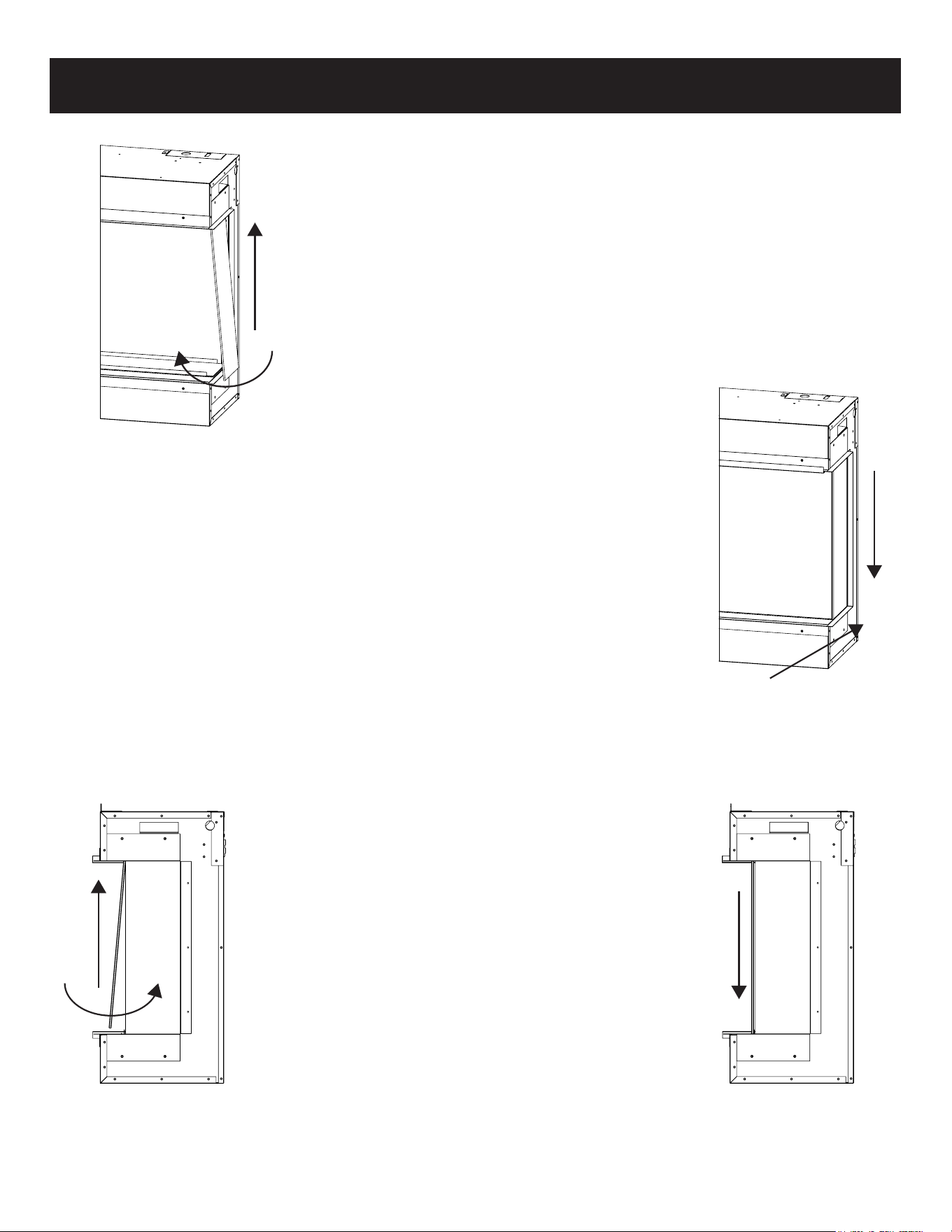
GLASS INSTALLATION
Installing Side Glass
4. Slide the glass down in to the bottom channel.
5. Push the glass back as far as it will go to make
installation of the front glass easier. See Figure 1.2.
Figure 1.1
1. The unit has 2 channels, one on the top and one on the
bottom to hold the side glass.
2. Insert the glass at an angle in to the top channel.
3. Swing the bottom edge of the side glass in to the unit.
See Figure 1.1.
Figure 1.2
Installing Front Glass
1. The unit has 2 channels, one on the top and one
on bottom to hold the front glass.
2. Using the included suction cups, insert the glass
at an angle in to the top channel.
3. Swing the bottom edge of the front glass in to the
unit. See Figure 2.1.
4. Slide the glass down in to the bottom channel.
See Figure 2.2.
Figure 2.1 Figure 2.2
15
(Fig 3-1)
N L1
N L1L1 L2 N
(Fig 3-2)
FUSE
BOX
LIGHT BLUE (N) NEUTRAL
BROWN (L1) LINE/HOT
( )
YELLOW/GREEN
GROUND
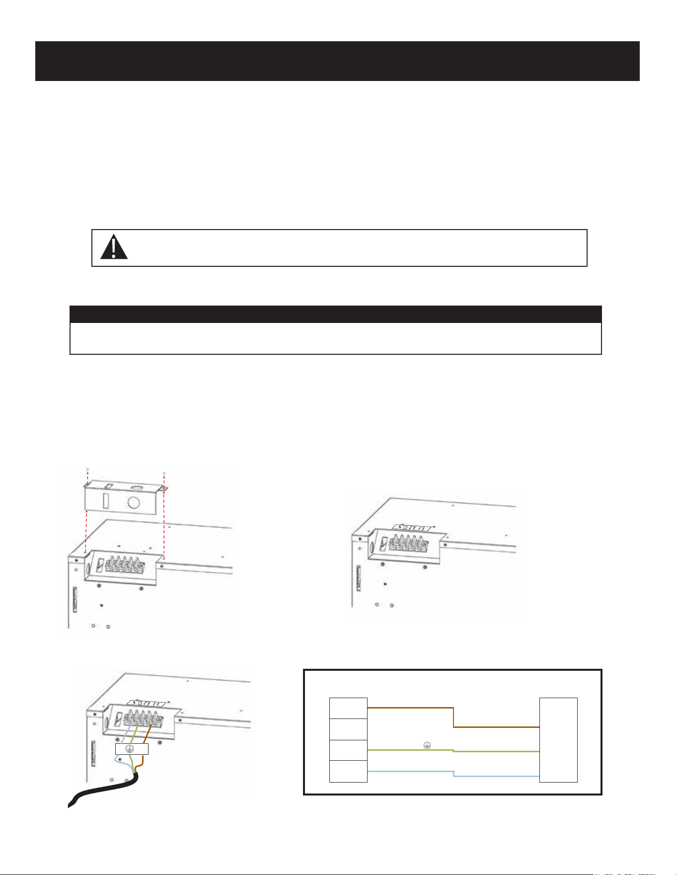
HARD WIRING
• Ensure power from the circuit breaker is off.
• Remove the 2 securing screws from the junction box cover plate, located on the top
left-hand, backside of the appliance (Fig 3-1).
• From the power supply wire, connect the yellow/green/bare copper wire to the ground (G),
the light blue wire to neutral (N), and the brown wire to Line 1 (L1) (Fig 3-2).
A qualified electrician must wire this fireplace to a dedicated 220~240 volt, 13 amp (EU)
10 amp (AU/NZ), circuit.
A 13 amp (EU) or 10 amp (AU/NZ) circuit is required. A dedicated circuit is preferred
but not essential in all cases. A dedicated circuit will be required if after installation,
the circuit breaker trips on a regular basis. Additional appliances on the same circuit
may exceed the current rating of the circuit breaker.
Note: Follow all national and local electrical codes.
TURN OFF POWER FROM CIRCUIT BREAKER FIRST
220~240 Volt Power (6,800 BTU’s):
Note:
There are 3 wires from the appliance junction box: light blue (neutral), brown (power L1), and
yellow/green/bare (ground) that are connected to 220~240V power source (circuit breaker panel).
FIREPLACE
JUNCTION/TERMINAL
16
The unit has a main power switch just in front of the glass on the top right hand side.
A hand-held remote is included.
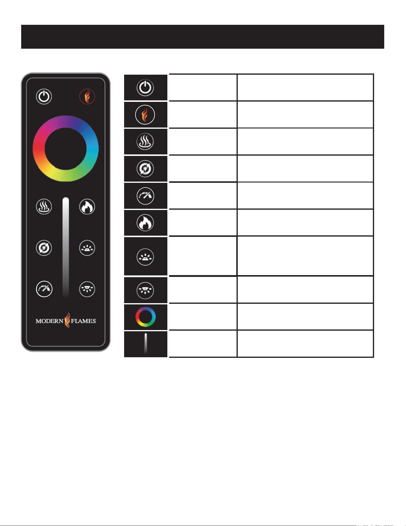
REMOTE CONTROL OPERATION
Power
Home
Heat
Mode
Speed
Flame
Ember Bed
Downlight
Color Wheel
Brightness
Slider
This will cycle the fireplace on and off. Upon
cycling power on, the fireplace will return to
the settings it had when it was cycled off .
If the fireplace is on, this button will act as a
reset and bring all colors back to the default
Modern Flames' signature color.
This will cycle the heater between high,
low and off .
All zones of the fireplace will cycle through
various demo modes - 7 & 3 color
gradient/fade, 7 & 3 color jump,
red/green/blue gradient.
This is the speed button. Pressing will cycle
the flame & ember bed speeds.
Speeds: Low, Medium, Default & High.
This is a zone setting. Touching this button
will allow you to change the color and
brightness of the flame by using the
color wheel and brightness slider.
This is the Ember Bed light adjustment button.
After pressing this button, the color ring and
brightness bar will be adjusted, and only the
color of the ember bed lamp will be adjusted.
Long press this button for 3 seconds to adjust
the optional accessory on or off.
This will cycle the selected zone through
the colors of the color spectrum.
This is a zone setting that controls the
color and brightness of the downlight.
This will adjust the brightness of the
selected zone.
Pairing remote or wall mounted touch control:
Before beginning, read pairing instructions in its entirety. Locate and familiarize yourself with the manual touch
controls on the fireplace and your hand held remote. Ensure remote has a battery installed.
1. On the fireplace touch controls, long press the on/off button for 3 seconds until a fast double beeping tone is heard
from the fireplace. The power indicator will also flash 3 times in 1 second. This places the fireplace in RF pairing mode.
2. Within 5 seconds of hearing the double beeping tone, either on the handheld remote or wall touch control, press
the power button repeatedly until another beeping tone is heard along with the indicator lights flashing. This is the
fireplace acknowledging that it has paired. An additional tone may also be heard; this is simply the fireplace
completing the pair mode.
NOTE:
• Pairing must be done within 5 seconds or the fireplace will time out of pairing mode.
• After the initial double beep is heard, do not long press the power button on the remote/pairing device to pair as this may not be
successful. Pressing the power button repeatedly is required to ensure the signal is sent from the remote/pairing device to the
fireplace.
• To clear any paired remotes/devices from the fireplace, locate the reset button on the fireplace, then long press the reset button
for 3 seconds. A beeping tone will indicate that the codes have been cleared. Once cleared, a new remote or wall touch control
can now be paired. This will also un-pair any APP that was paired to the fireplace.
17
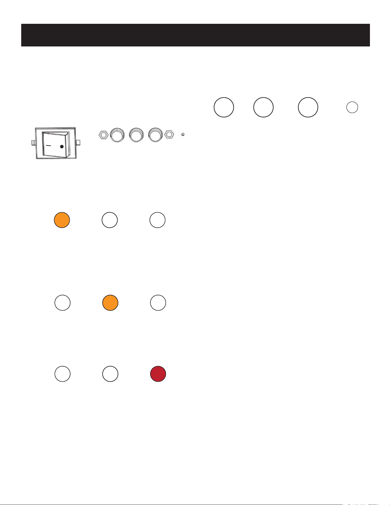
Toggle Switch: The fireplace has a main toggle
switch located next to the manual controls.
The toggle switch is in front of the glass on
the top right side of the viewing area.
When the “-” side of the toggle switch
is depressed, the “O” pops up. This is the
power-on state of the fireplace.
Power Indicator lights: The fireplace is
equipped with Power indicator lights
which are located on the upper right
corner of the fireplace viewing area.
First light: When the fireplace is in the
power-on state, an amber light turns on.
The light shows the fireplace is energized
and on stand-by for any commands. The
amber light turns OFF when the fireplace
is turned on and operating.
Second light: When the fireplace is powered
on and the heater is set to low, the second
light turns on. Light will fade away after
6 seconds.
Third light: When the fireplace is powered
on and the heater is set to high, the
third light turns on. Light will fade
away after 6 seconds.
Manual Controls
The fireplace has manual controls located next to the
toggle switch, in front of the glass on the top right
side of the viewing area.
Power On/Off button: Press once, indicator light
turns off and fireplace power turns on. All
functions enabled. Press again, flame turns off
and fireplace goes to standby. NOTE: Long
pressing this button for 3 seconds places
fireplace in RF pairing mode.
Heat Button: Pressing heat button cycles the heater
and blower on/off. Settings: Heater and blower
OFF, Low Heat, and High Heat. Indicator light will
match according to status. NOTE: On US LPM, low
and high heat have the same heat output when
wired for 120 V. Long Press the heater button for
5 seconds to lock/unlock the heater.
Preset Color Button: Press preset color button to
cycle through the 8 preset color options. This
changes color of all three zones: the flame,
ember bed and down light. Colors in order of
appearance: MF orange-red-orange-golden
orange-green-aqua-blue-magenta
Resetting button: Clears any paired remotes/devices
from the fireplace. Once cleared you can pair a
new remote or wall touch control. This will also
un-pair any APP that was paired to the fireplace.
After long pressing the reset button for 3
seconds, a beeping tone will be heard indicating
that the pairing codes have been cleared.
Buzzer Tone Change: Long press the on/off and
preset color button at the same time to enter the
beeping tone cycle mode. Continue to long press
both buttons to cycle through the 4 tone options.
The tone will change every 2 seconds while
releasing the buttons will act as the selection of
the tone. The tones in order of appearance are;
tone-1, tone-2, tone-3, and silent mode.
Power
Turns unit
on/off
Heat
Cycles
heat low/
high/off
Color
Changes all
fireplace colors
together
Reset
Resets
unit
SETTING CONTROLS
18
SETTING CONTROLS
NOTE: When silent mode is selected, a tone will still
be present for performing system functions
such as remote pairing or Wi-Fi pairing.
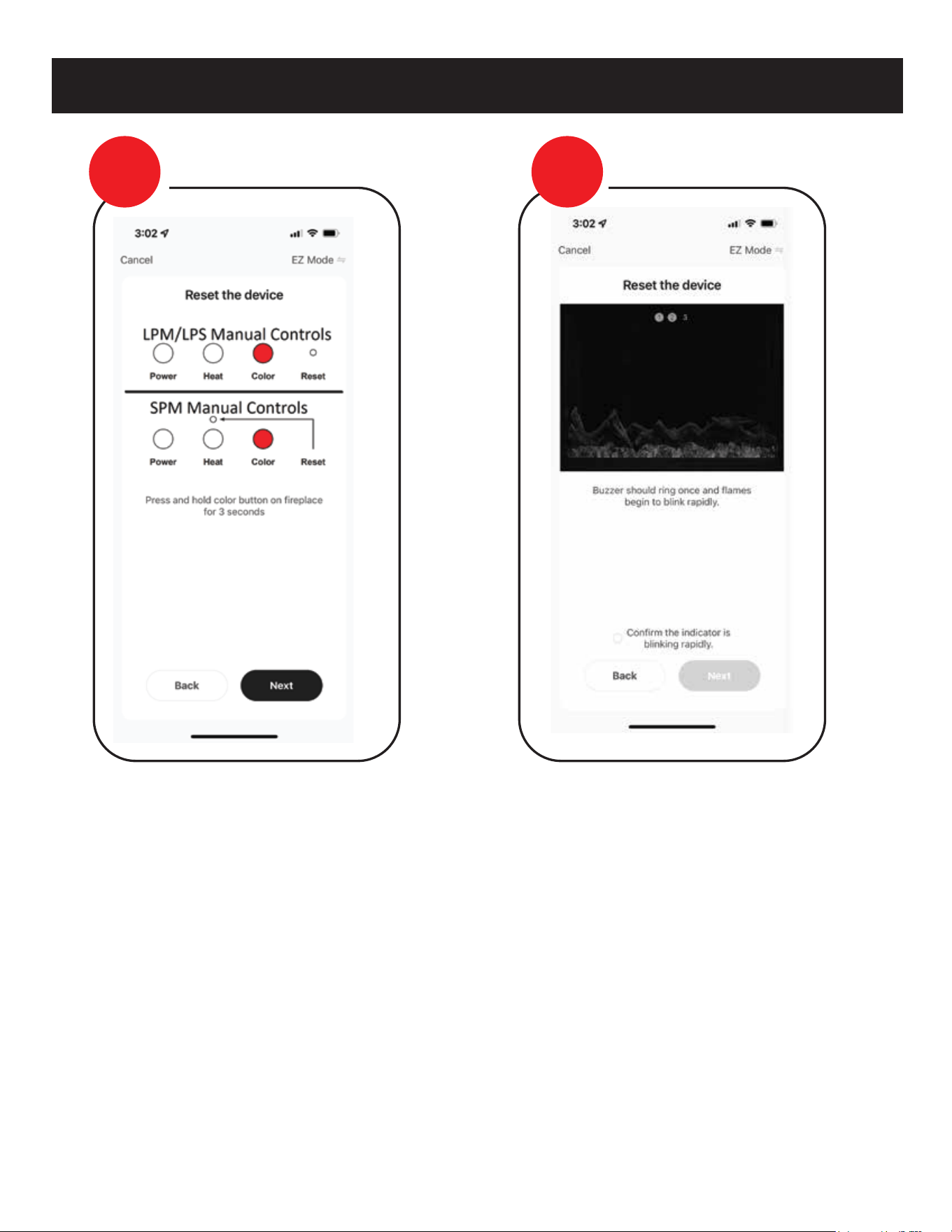
Placing in Wi-Fi Paring Mode:
-EZ Mode: While the fireplace is ON, long press
the Preset Color button for 3 seconds. An
audible beeping tone will sound and the flame
light, ember bed light, and down light will turn
to white and begin flashing rapidly. Fireplace is
now in EZ pairing mode, which lasts for
2 minutes.
-AP Mode: While the fireplace is ON, long press
the Preset Color button for 6 seconds. Two
audible beeping tones will sound and then only
the FLAME LIGHTS and nothing else will turn to
white and begin flashing slowly. Fireplace is now
in AP pairing mode, which lasts for 2 minutes.
NOTE: Fireplace is also equipped with Bluetooth
pairing. There is no mode setting for the
Bluetooth as the APP will automatically
detect the Bluetooth signal for pairing when
attempting to pair fireplace to Bluetooth.
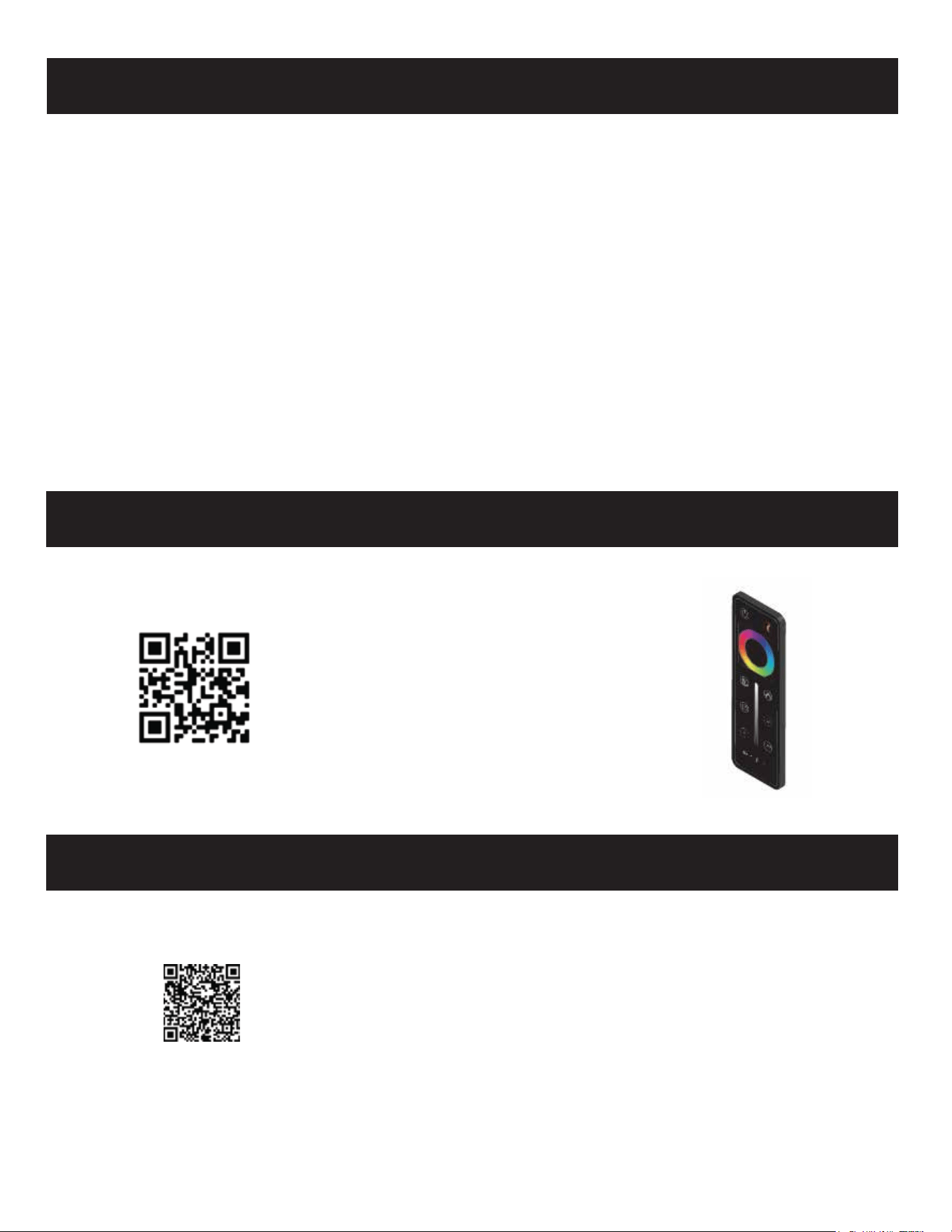
Link to video on how to change
battery in Pro Series remote
CR2025 battery
HOW TO CHANGE REMOTE BATTERY
LINK TO DOWNLOAD MOBILE APP
Link to Mobile App for tablets & phones
19
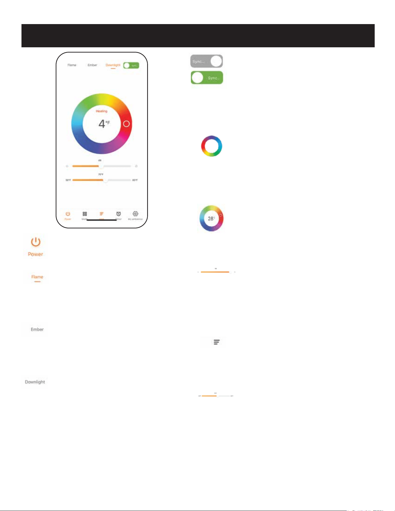
WIFI REMOTE
Power
Powers unit On & Off.
Flame
This is the flame zone adjustment tab.
After pressing this tab, the color ring
and brightness bar can be adjusted.
Ember Bed
This is the ember bed zone adjustment
tab. After pressing this tab, the color
ring and brightness bar can be adjusted.
Downlight
This is the downlight zone adjustment
tab. After pressing this tab, the color
ring and brightness bar can be adjusted.
Sync
This is a synchronization selector, used
to synchronize the current color on the
color wheel to all of the zones
(Flame/Ember Bed/Downlight). Grayed
out SYNC is when synchronization is
“OFF”. Green SYNC is when
synchronization is “ON”.
Color Wheel
This is the color adjustment wheel for
all zones. Keeping contact on the color
circle, the color of the selected zone will
change continuously base on where you
have your finger.
Temperature Read Out
The number in the color circle is the
built-in thermostat temperature reading
of the fireplace.
Brightness Control
Brightness adjustment, for all zones
depending on tab selected or if sync is
on. The brightness of the fireplace
changes in real time as the slider is
moved.
Heat Control
Heat controls open a drop-down menu.
The menu displays off, low, and high.
Can be used without thermostat.
Thermostat Slider
Normally inactive while heater is “ON.”
To use the thermostat while the heater
is “ON,” activate the thermostat by
setting the slider to the desired
temperature.
Note: Does not save when turned “OFF.”
20
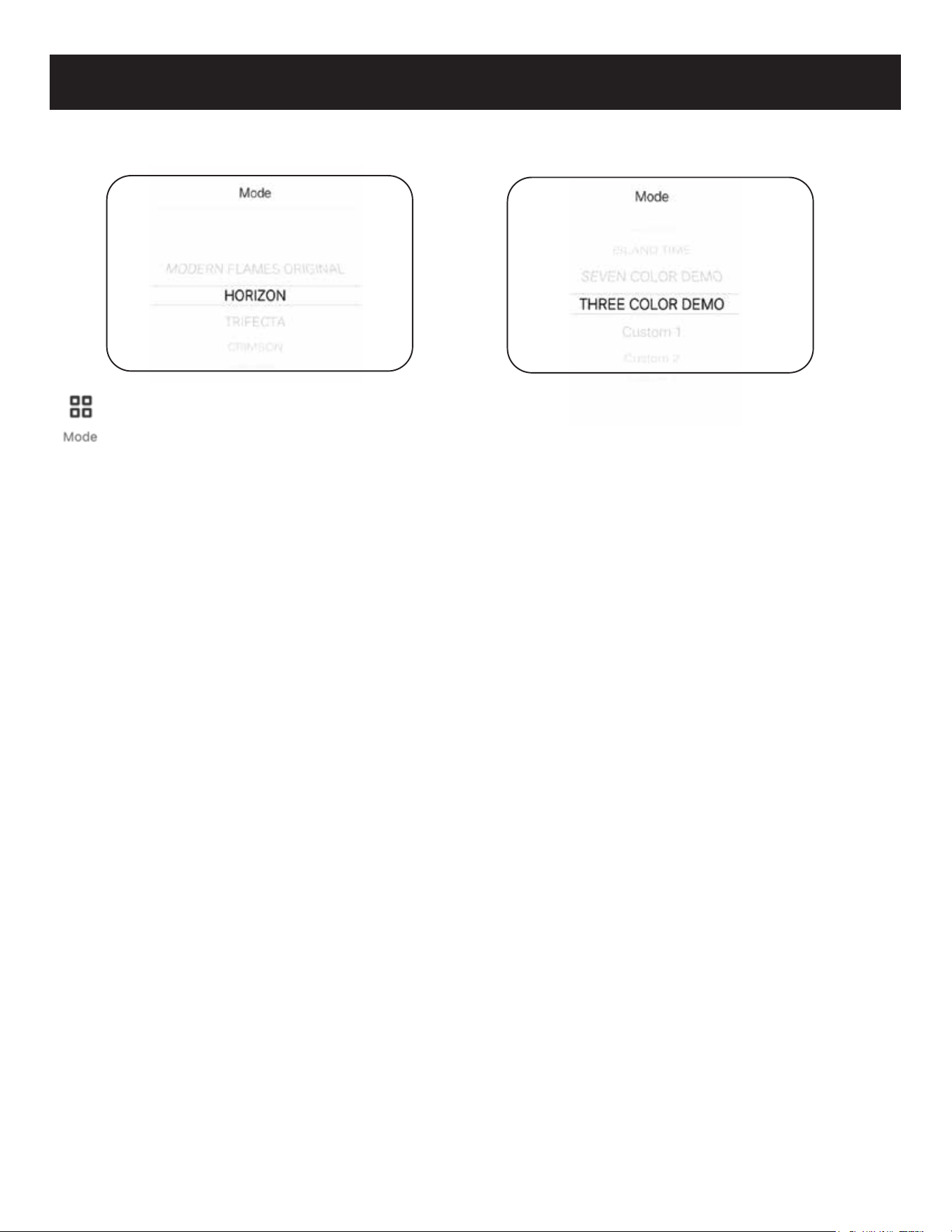
Mode Sub Menu Preset Menu
WIFI REMOTE
Mode Button
Opens a sub menu for selecting presets.
PRESET MENU
> Modern Flames Original
Modern Flames Orange (Static).
> Horizon
Same as remote control, 7 color
gradient cycle
R->G->B->RG->RB->GB->RGB.
> Trifecta
Same as remote control, R-G-B
three color gradient cycle.
> Crimson
Same as remote control,
3 color gradient cycle R->G->B.
> Hillside
Same as remote control,
green monochrome
fade cycle.
> Island Time
Same as remote control blue
monochrome fade cycle.
> Seven Color Demo
Same as remote control, 7 color jump
cycles: R->G->B->RG->RB->GB->RGB.
> Three Color Demo
Same as remote control, 3 color jump
cycles: R->G->B.
> Custom 1
Custom mode can be modified from
“My Ambience” setting. The default
color is Red.
> Custom 2
Custom mode can be modified from
“My Ambience” setting. The default
color is White.
> Custom 3
Custom mode can be modified from
“My Ambience” setting. The default
color is Blue.
21
(default)
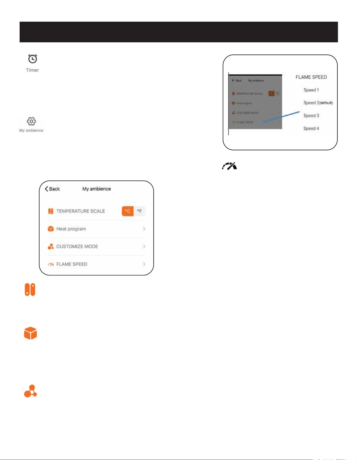
WI-FI REMOTE
> Temperature Scale
Set the temperature unit according to needs.
“°C” for Celsius and “°F” for Fahrenheit. The
main temperature read out will change
accordingly.
> Heat Program
Setup a custom weekly schedule. This
includes the state of the fireplace, the heater
level and thermostat for the heat if desired.
(See Heat Program Sub menu continued for
more info.)
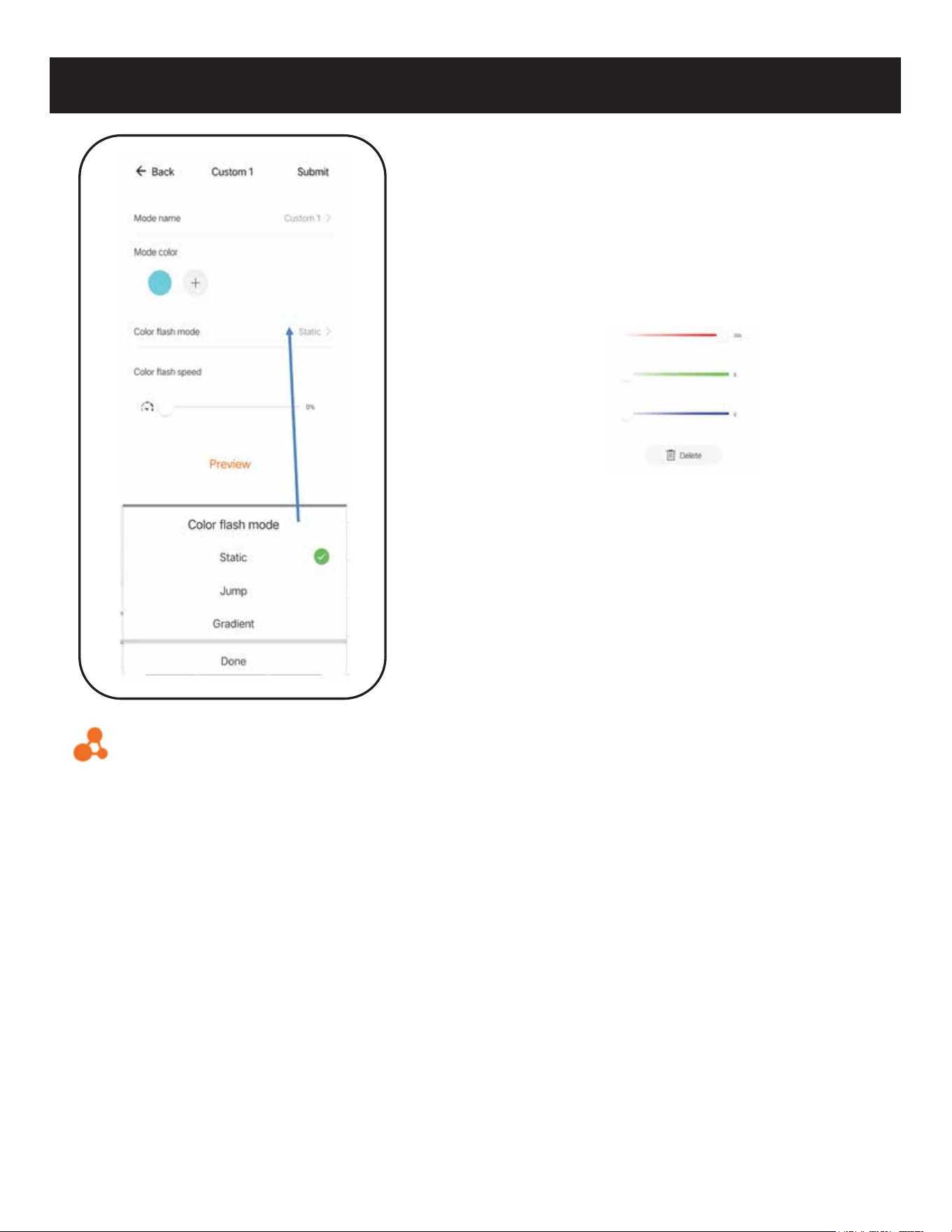
> Customize Mode
Configure the custom modes via
4 options: mode name, mode color, Color
flash mode, Color flash speed. Includes a
preview function. (See Customize Mode
Sub menu continued for more info.)
Timer
Pressing the timer button will pop up a
sub-menu with 10 options to choose from:
0.5-1-2-3-4-5-6-7-8 hours-cancel. Once the
selected time has elapsed, the fireplace will
turn off.
Ambience Setting
The Ambience Setting button will open up a
second window where customizations can
be performed, including temperature scale
setting (C/F), Weekly/Heat programming,
Custom mode configuration, and changing
speed of the flame and ember bed.
> Flame Speed
Change between 4 speeds:
Low, Medium, Default & High.
22
Power
Off
Turn On
Cancel
Heat
Level
Off
Low
High
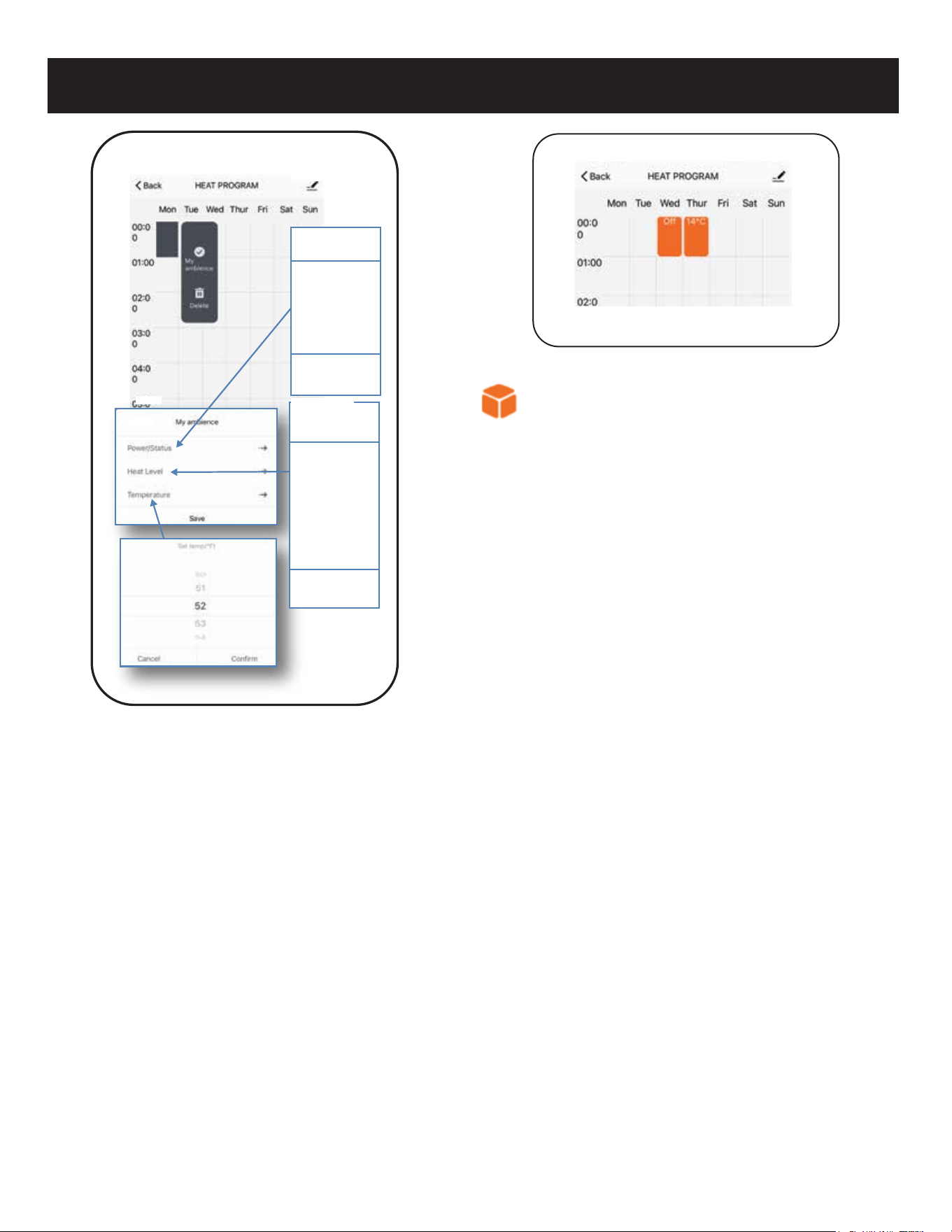
WI-FI REMOTE
HEAT PROGRAM
SUB MENU CONTINUED
> Power
Sets fireplace status (no heat)
OFF/ON.
> Heat Level
Sets Heat Level: OFF/LOW/HIGH.
> Temperature
Temperature Level for the heater to
turn on if the ambient temperature
falls below the set temperature
(High Heat.)
23
WI-FI REMOTE
> Mode Color
Mode color: In the Static mode, only one
color can be selected. After clicking the
color symbol, you can change to
additional colors. When using the
Jump/Gradient feature, 8 colors can be
programmed by clicking “+” color.
By adjusting the color sliders, select the
corresponding RGB value to obtain the
desired color combination..
> Color Flash Mode
Customizing how the color changes.
>Static
No change in brightness and
flash and only one color can be
selected.
> Jump
Cycles between selected colors,
up to 8. Jump speed is selected
using the speed slider.
> Gradient
Color progression between
chosen colors, up to 8.
Gradient speed is selected
using the speed slider.
> Preview
Will Preview any customization being
made.
CUSTOMIZE MODE SUB MENU
> Mode Name
Custom name of selected mode
(default will be present until changed).
24
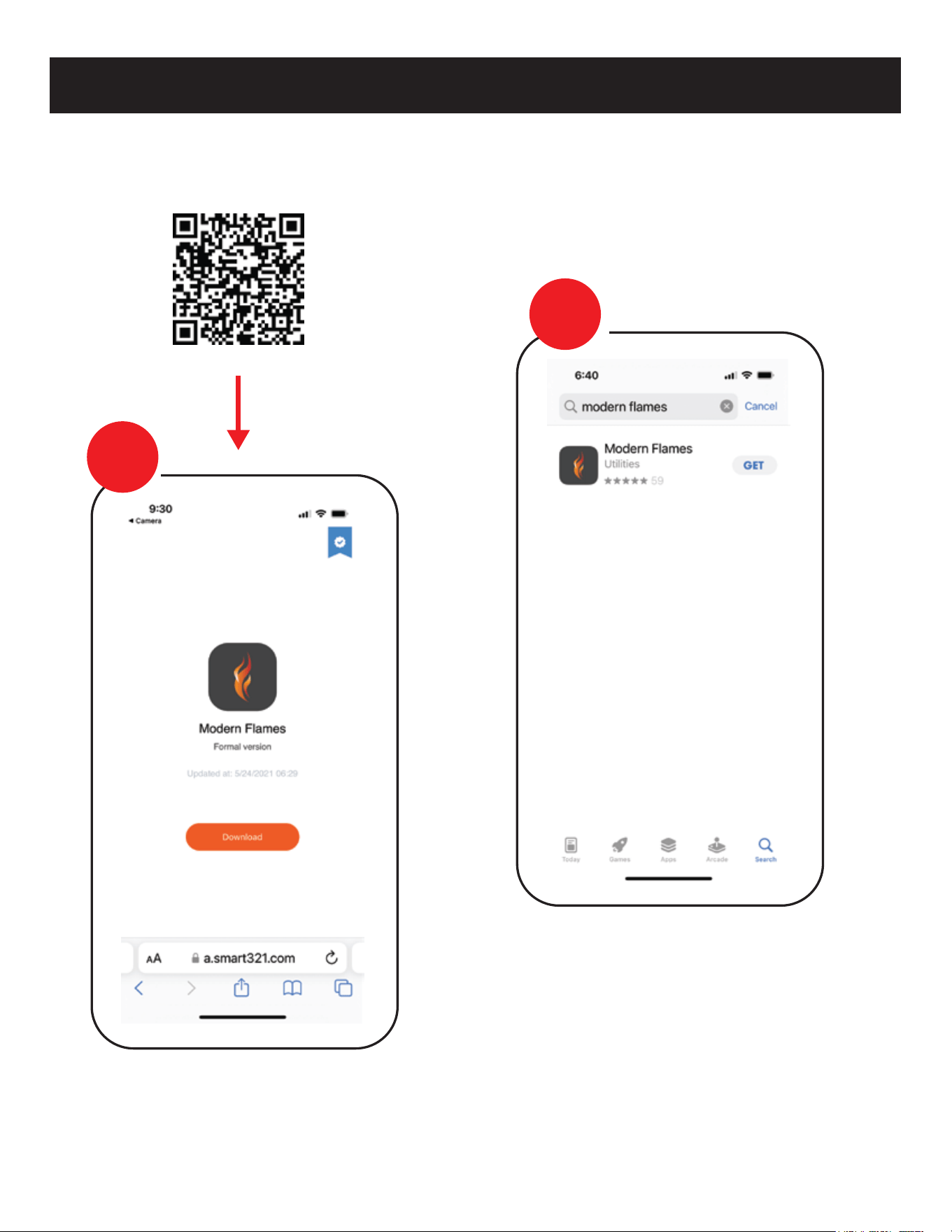
WI-FI INITIAL LOG-IN
> After Download & Installed
Login to Modern Flames app.
Search for and install the “MODERN FLAMES” app from Google Play or
Apple App store or scan the QR code.
> App Example
STEP
1
STEP
2
25
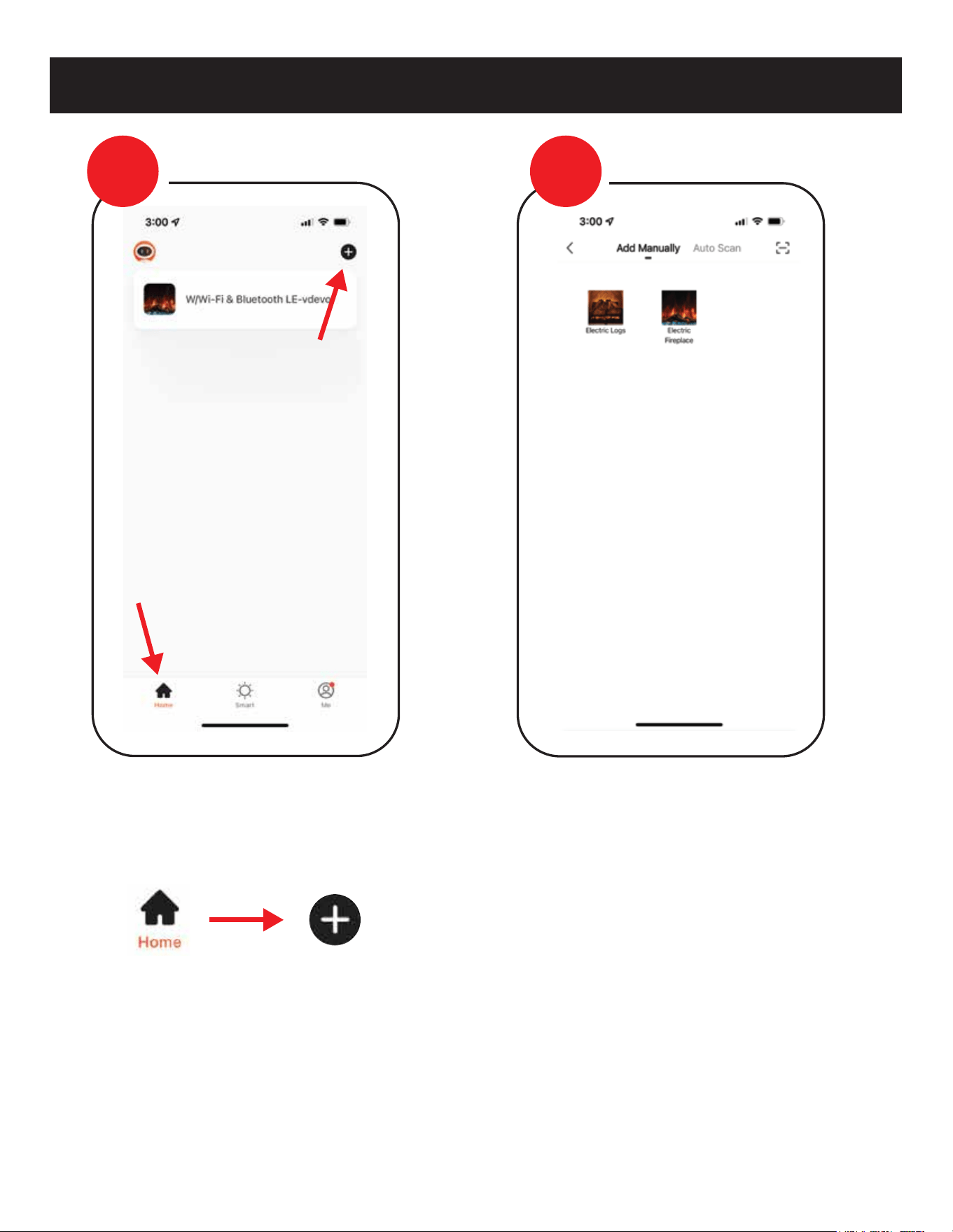
WI-FI PAIRING
> Once Opened and Logged In
From the home page, select the add “+”
symbol.
> Select Fireplace
Select series of fireplace that will be
pairing too and follow instructions.
STEP
3
STEP
4
26
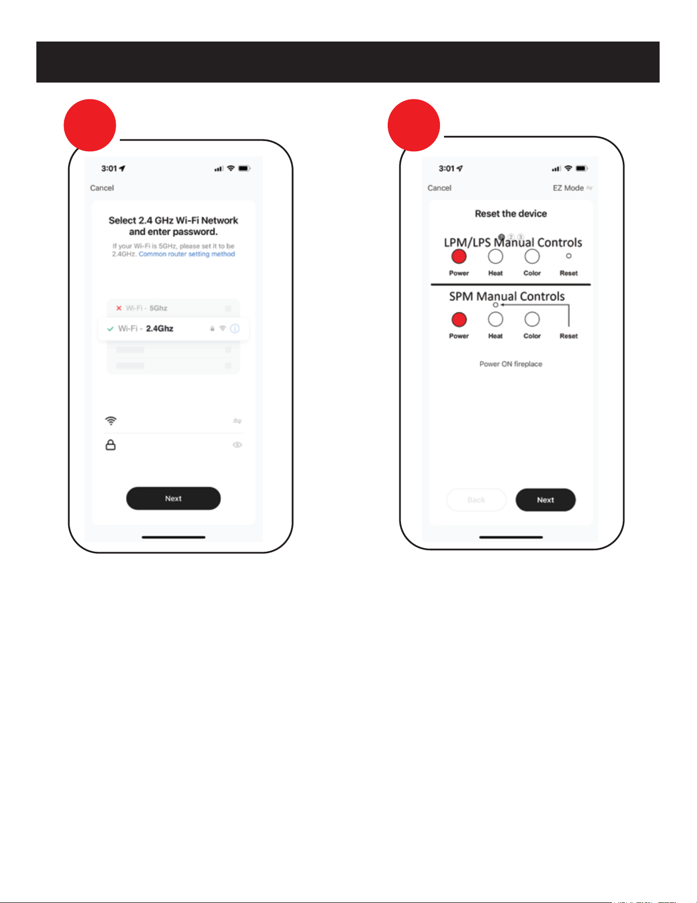
WI-FI REMOTE
> Ensure Fireplace is ON
Using the fireplace manual touch
controls, turn ON the fireplace.
> WiFi Information
If pairing via Wi-Fi you must use 2.4 GHz
Wi-Fi, and must have information filled
out to move to next step.
STEP
5
STEP
6
27
WI-FI REMOTE
> Place Fireplace in Pairing Mode
Once fireplace is “ON”, place fireplace in
Wi-Fi pairing mode following the
instructions for pairing mode on the
APP. There are 3 types of pairing EZ
mode, AP mode and a Bluetooth mode.
EZ and AP modes will be displayed
accordingly on the top right of the
screen. Example displayed is EZ mode.
> Wi-Fi Pairing Confirmed
EZ pairing mode is confirmed with a
single audible beeping tone is heard and
all the lights begin to blink rapidly
AP pairing mode is confirmed with two
audible beeping tones are heard and
ONLY the FLAME begins blinking slowly.
*Select confirm to move forward to Next step
Note: Device remains in pairing mode for
2 minutes.
STEP
7
STEP
8
28
WI-FI REMOTE
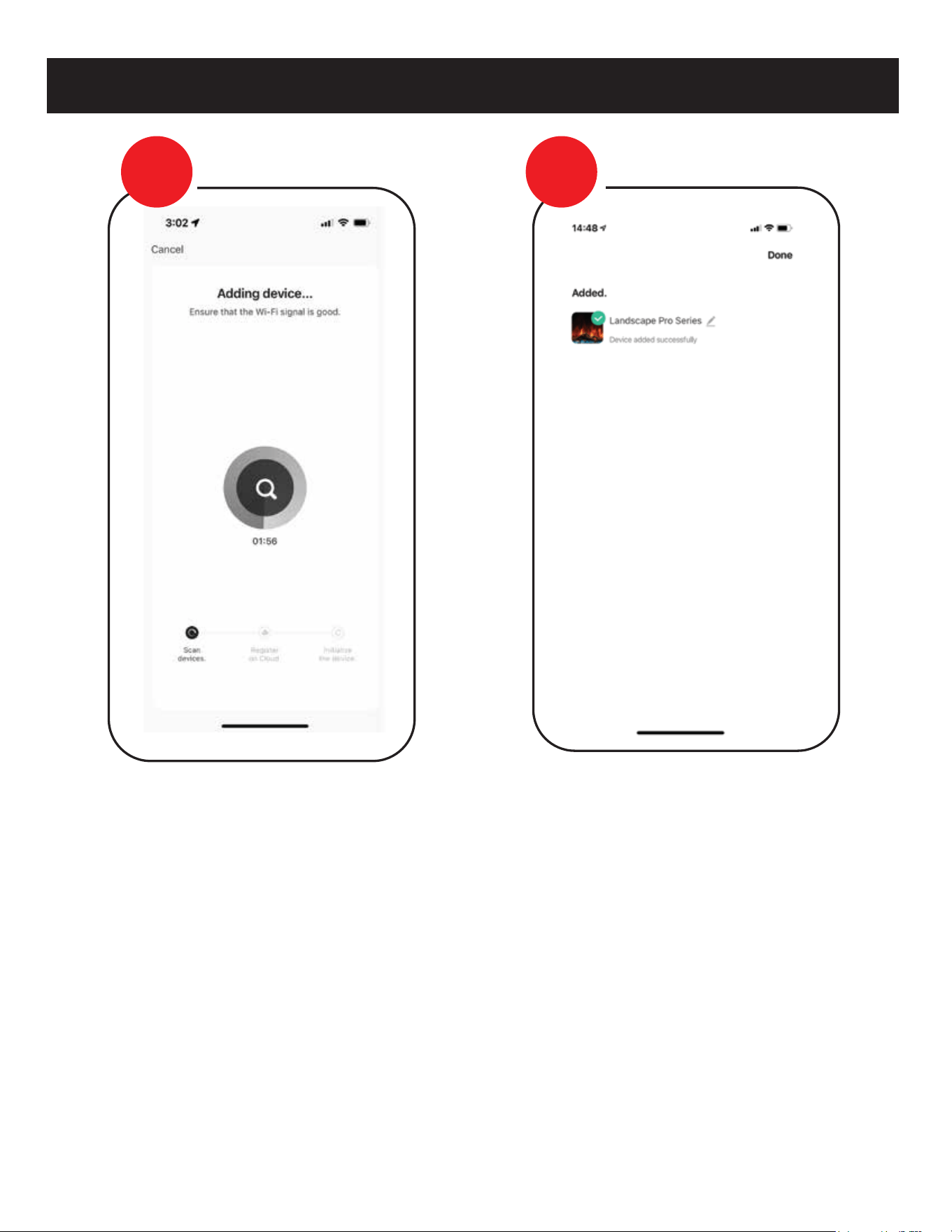
> Device Paired Successfully
NOTE: Do not turn off or disconnect the
fireplace from power while pairing the Wi-Fi
or performing updates. Failure to do so can
result in damage to the electrical components
of the fireplace. Damage as a result of this
may not be covered under warranty.
> Pairing
Device & APP should now begin to pair.
Depending on Wi-Fi this can take up the
entire 2 minutes to pair, or it may need to
be repeated more than once, if the signal
isn’t captured the first time.
Question or assistance about pairing device contact.
AUSTRALIA/NEW ZEALAND
info@modernflames.com or call 07 5630 6837
Monday-Friday, 9:00 am - 4:00 pm (AEST).
EUROPE
europe@modernflames.com
or call +46 762 09 58 09
Monday-Friday, 9:00 am - 4:00 pm (CEST).
customerservice@modernflames.com
or call (877) 246-9353
Monday-Friday, 8:00 am - 5:00 pm (MST).
STEP
9
STEP
10
29
MAINTENANCE
30

TROUBLE SHOOTING
PROBLEM POSSIBLE CAUSE CORRECTIVE ACTION
Nothing comes on
(touch screen, etc.)
Touch Screen Comes on
- then nothing
Fireplace turns off and
will not turn back on
Can operate fireplace
functions with manual
controls but not
remote control
Heater does not provide
heat when on
Flame is not visible
when unit is turned on
Fireplace lights up but there
is no flame image
or flame image frozen
Fireplace is squeaking when
flame image is on
A. Breaker tripped or circuit has no
power
B. Internal component is frozen
and needs to be reset
C. Loose connection
D. Defective component
A. Reset breaker, test circuit for power, check
power switch
B. Turn power off at the main breaker for 60
seconds. Turn power back on.
C. Inspect wiring for loose or damaged
connection
D. Replace motherboard, touch control or
power switch
A. Not operating touch control
properly with finger
B. Loose connection on mother-
board
C. Motherboard is defective
A. Press flat part of finger firmly on the touch
screen and apply moderate pressure
B. Check functions with remote control. If
functional, check connections on mother-
board
C. Replace Motherboard
A. Fireplace has overheated and
safety disc has snapped or
circuit breaker has tripped
A. Turn the main breaker to the “off” position
for 60 seconds. Next flip the breaker back
to “on” position.
A. Low Batteries
B. Remote not paired properly
C. Remote control defective
A. Replace batteries in remote control with -
CR2025
B. With the fireplace ON, press and hold the
Power button for about 3 seconds until you
hear the buzzer sound twice and the power
indicators begin to flash. Within 5 seconds on
the hand held remote or wall touch control
press the Power button repeatedly until the
buzzer sounds again and the indicators flash
acknowledging that it has paired. You may
also hear another buzzer and the pair is now
completed.
C. Replace remote control
A. Wiring is loose
B. Snap disc tripped
C. Heater core is defective
A. Disconnect unit from power source and
inspect for loose connections
B. Turn off for 5 minutes to reset
C. Replace Heater Core
A. Wiring is loose
B. LEDs defective
C. Motherboard is defective
A. Disconnect unit from power source and
inspect for loose connections
B. Replace LEDs
C. Replace motherboard
A. Wiring for motor is loose
B. Spindle rod came loose
C. Motor is defective
A. Disconnect unit from power source and
inspect for loose connections from motor
B. Reconnect spindle rod
C. Replace motor
A. Fireplace spindle/rod is
contacting to metal
B. Motor is defective
A. Apply lithium grease or any standard
grease to contacts with rod and metal
and rubber bushing.
B. Replace motor
31

FREQUENTLY ASKED QUESTIONS
Q. How do you change the optional Wall Mount Touch Control to
Fahrenheit/Celsius?
A. Long press on the up and down arrows on the fireplace to
toggle between Fahrenheit and Celsius.
Q. What distance can the remote be used from the fireplace?
A. Optimal distance for the remote control is maximum 20 feet.
Q. Can you turn on the fireplace via the manual control and off
via the remote (or vise versa)?
A. Yes.
Q. Can the fireplace be installed outside?
A. Yes. Reference outdoor installation section for requirements.
Q. Does the fireplace need to be on a dedicated 15 Amp circuit?
A. Yes, It is recommended that the fireplace be on a dedicated
13 (EU) 10 Amp (AU/NZ) circuit
Q. What thickness of sheetrock should be used for the recessed
installation?
A. 12 mm or 16 mm, thinner is recommended for tile facade.
Q. How often do the batteries in the remote need to be replaced?
A. Annually, possibly more with heavy use.
Q. Is there a remote receiver in the fireplace that requires batteries?
A. No, only the actual remote requires batteries.
The rest of the fireplace runs entirely off of the main power
supply.
Q. How do I reset the unit?
A. Turn power off at the breaker for 1 minute.
Q. How do I install the Optional Wall Mount Touch Control and Wi-Fi
App?
A. Optional wall control & Wi-Fi app instructions available for
download on Modern Flames’ website
32

FCC CAUTION
This device complies with part 15 of the FCC Rules. Operation is subject to the following two
conditions: (1) this device may not cause harmful interference, and (2) this device must accept
any interference received, including interference that may cause undesired operation.
Any changes or modifications not expressly approved by the party responsible for compliance
could void the user's authority to operate the equipment.
NOTE: This equipment has been tested and found to comply with the limits for a Class B
digital device, pursuant to Part 15 of the FCC Rules. These limits are designed to provide
reasonable protection against harmful interference in a residential installation. This
equipment generates, uses and can radiate radio frequency energy and, if not installed and
used in accordance with the instructions, may cause harmful interference to radio
communications. However, there is no guarantee that interference will not occur in a
particular installation.
If this equipment does cause harmful interference to radio or television reception, which can
be determined by turning the equipment off and on, the user is encouraged to try to correct
the interference by one or more of the following measures:
-- Reorient or relocate the receiving antenna.
-- Increase the separation between the equipment and receiver.
-- Connect the equipment into an outlet on a circuit different from that to which the receiver
is connected.
-- Consult the dealer or an experienced radio/TV technician for help.
To maintain compliance with FCC’s RF exposure guidelines, this equipment should be installed
and operated with minimum distance between 20cm the radiator your body: Use only the
supplied antenna.
33

__________________________________________________________________________________________________
__________________________________________________________________________________________________
__________________________________________________________________________________________________
__________________________________________________________________________________________________
__________________________________________________________________________________________________
__________________________________________________________________________________________________
__________________________________________________________________________________________________
__________________________________________________________________________________________________
__________________________________________________________________________________________________
__________________________________________________________________________________________________
__________________________________________________________________________________________________
__________________________________________________________________________________________________
__________________________________________________________________________________________________
__________________________________________________________________________________________________
__________________________________________________________________________________________________
__________________________________________________________________________________________________
__________________________________________________________________________________________________
__________________________________________________________________________________________________
NOTES
34

112023
Copyright © 2023 RPG Brands (Modern Flames). All rights reserved. Products and specifications subject to change without notice.
The product images shown are for illustration purposes only and may not be an exact representation of the product.
DO NOT RETURN TO STORE!
CALL US FIRST
For immediate help with installation, product information or
if your product arrives damaged, please call our toll-free number at:
AUSTRALIA/NEW ZEALAND
EUROPE
+46 762 09 58 09
1-877-246-9353
07 5630 6840
Or email us at:
Or email us at:
customerservice@modernflames.com modernflames.com
(Monday - Friday, 8:00AM - 5:00PM, AZ MST)
(Monday - Friday, 9:00AM - 4:00PM, CEST)
(Monday - Friday, 9:00AM - 4:00PM, AEST)
europe@modernflames.com
info@modernflames.com
Or email us at:
OUR STAFF IS READY TO PROVIDE ASSISTANCE