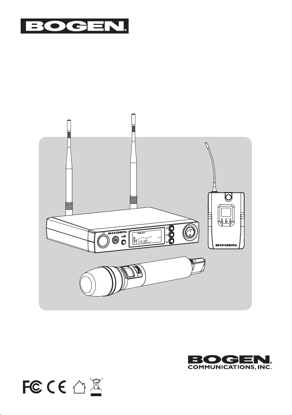
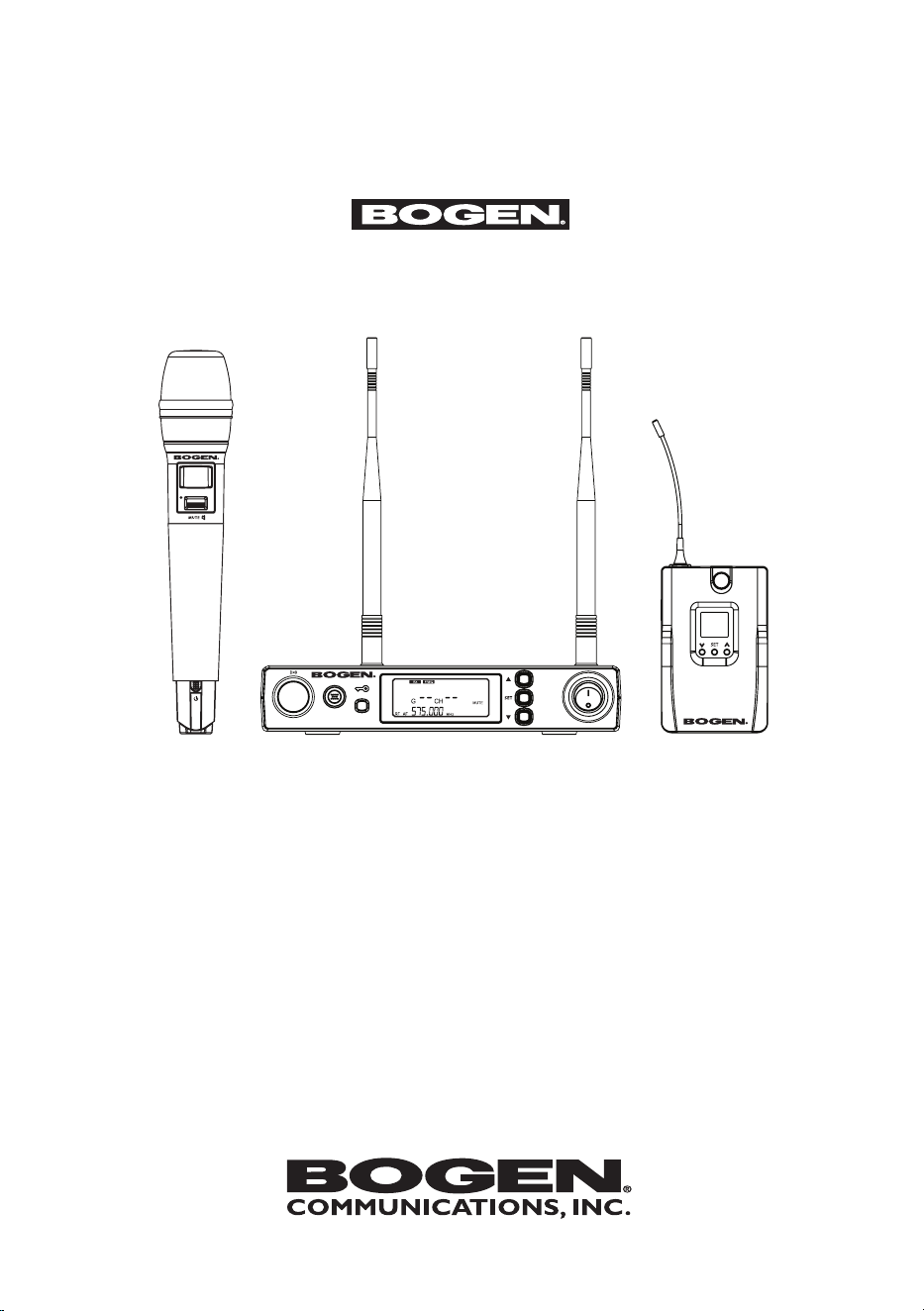
UDR
8011
UHF PLL SINGLE CHANN EL
DIVERSITY RECEIVER
UHF PLL TRANSMITTER
UBP
8011
UHF
8011
BP/HH
UHF PLL SINGLE CHANNEL DIVERSITY
WIRELESS SYSTEM
www.bogen.com
©2019 Bogen Communications, Inc.
Specifications are subject to change.
740-00078D 1903
INSTRUCTION MANUAL
UHF8011BP/HH
Model
UHF PLL SINGLE CHANNEL DIVERSITY
WIRELESS SYSTEM

INSIDE FRONT PAGE INTENTIONALLY LEFT BLANK

1. Notes for System Operation 1
2. Features ..........................................1
3. Model Specications ...............................2
3-1 UDR8011 UHF PLL Single Channel Diversity Receiver ............. 2
3-2 UHT8011 UHF PLL Hand Held Transmitter . . . . ..... . . . . ........... . .3
3-3 UBP8011 UHF PLL Body Pack Transmitter ..........................3
3-4 BCLM1 Condenser Lavalier Microphone ...... . . . . . . . . . . . . . . .. . . .....4
3-4 UHFHSMB Headset Microphone ....................................4
4. Description of Parts ................................5
4-1 UDR8011 Receiver Unit Callouts - Front View .. . . . . . . . . . ...... . . . . . . 5
4-2 UDR8011 Receiver Unit Callouts - Rear View .. . . . . . . . . . . . . . . . . . . . ..6
4-3 UDR8011 Receiver LCD Display Callouts . . . . . . . . . . . . . . . . . . . . . . .....7
4-4 UHT8011 Hand Held Transmitter Callouts . . . . . . . . . . . ...... . . . . . . . . . . 8
4-5 UBP8011 Body Pack Transmitter Callouts . . . . . . . .. . .. . . . .. . .. . . . . . . . 9
4-6 BCLM1 Condenser Lavalier Microphone Callouts . . . . . . . . . . . . . . . . .. 10
4-7 UHFHSMB Headset Microphone Callouts . . . . . . . . . . . . . . . . . . . . . . . . 10
4-8 Accessories
5. Connecting ........................................11
5-1 How to Connect to the UDR8011 Receiver .........................11
5-2 1. UHT8011 Hand Held Transmitter Installation . . . . . . . . . . . . . . . . . . . . 12
2. UBP8011 Body Pack Transmitter Installation . . . . . . . . . . . . ....... . 12
6. Instructions for Use 13
6-1 1. How to Set UDR8011 Receiver Parameters ...............13-14
2. UDR8011 Receiver Volume Adjustment .........................15
3. UDR8011 Receiver Sync Pairing .................................15
6-2 How to Set UHT8011/UBP8011 Transmitter Parameters ....16-17
7. Additional Product Instructions 18
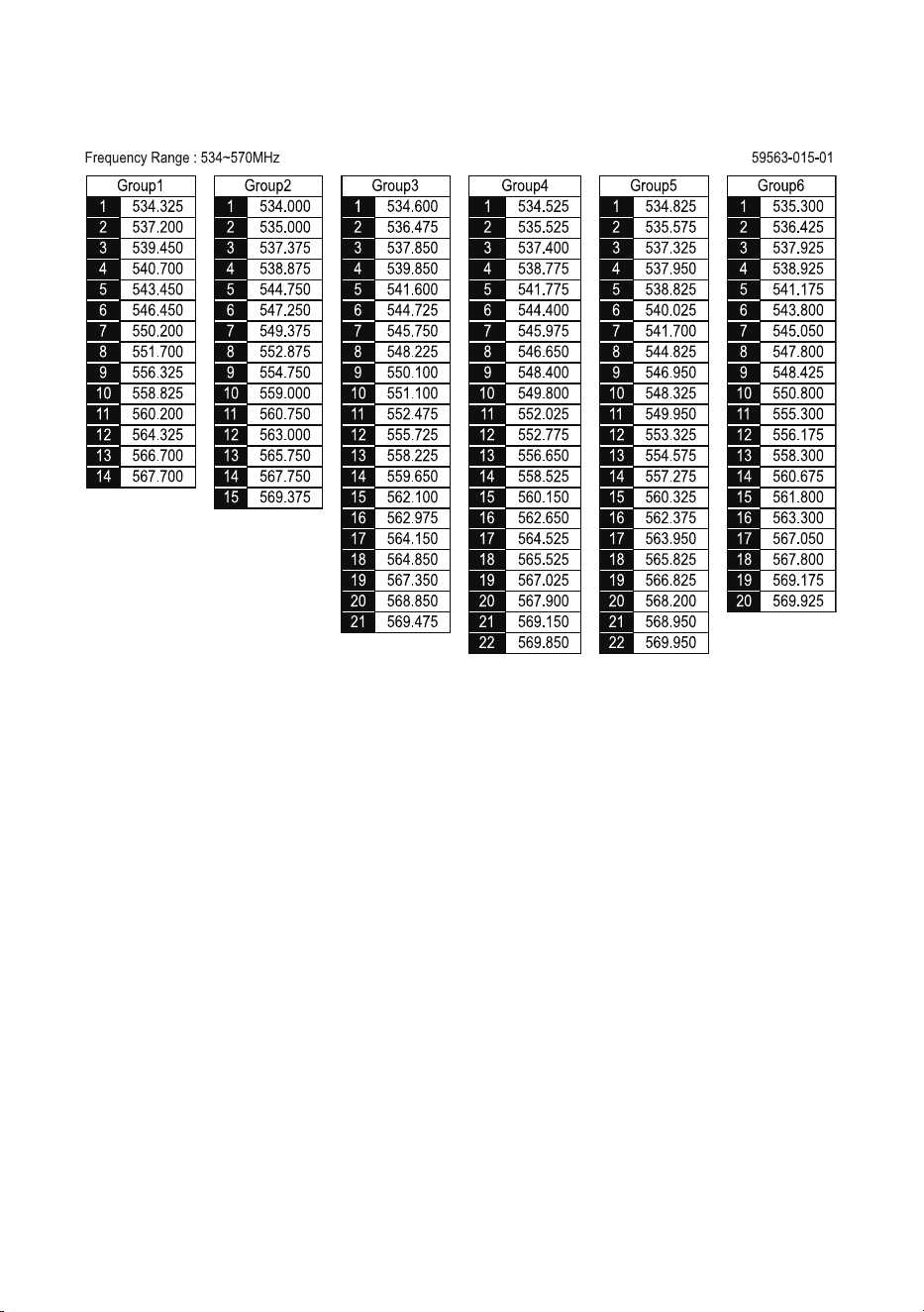
8. Wireless System Frequency List 19
9. Warranty 20
TABLE OF CONTENTS

1
1. Notes for System Operation
2. Features
• Before connecting the power, check that the power requirement shown
on the unit is the same as the power output on the adapter supplied.
• Do not operate the unit where humidity and temperature are high.
• Dry your hands before operating the system.
• Keep the unit away from re and heat source.
• Turn the volume to minimum on both the mixer and amplier before
setting up and powering on the system.
• Six groups are provided as default. Groups can contain up to
22 default channels.
• 1,440 channels to choose from.
• 36MHz Bandwidth
• Ultrasonic pairing for synchronized setting of all parameters
between receiver and tranmitter.
• Channel Scan capable
• Adjustable Receiving Sensitivity
• Digital Volume Control
• Automatic Transmitter Power Off
2
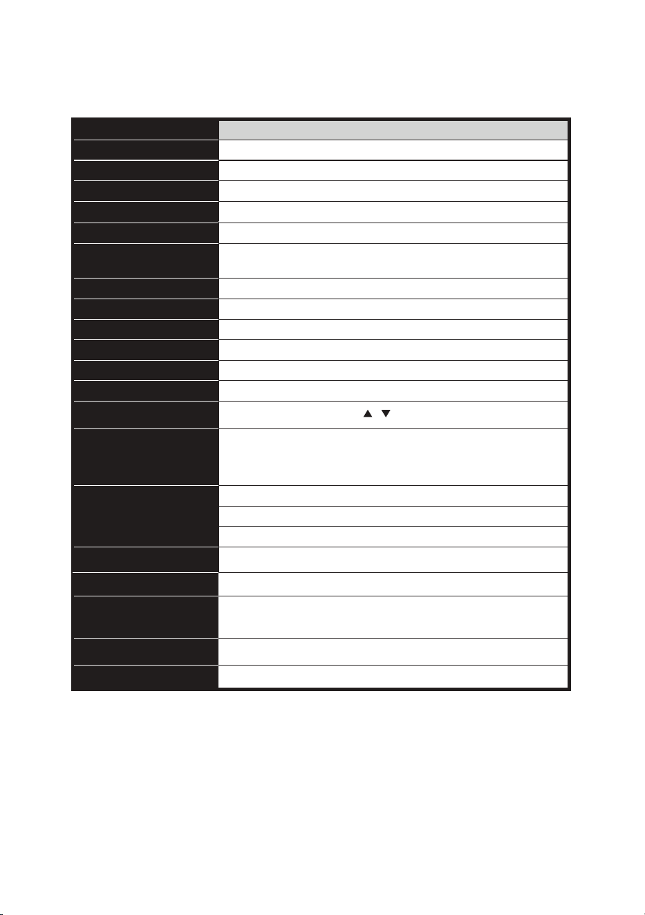
3. Model Specications
3-1 UDR8011 UHF PLL Single/Dual Channel Diversity Receiver
MODEL
Frequency Mode
Phase-locked loop (PLL)
Frequency Range
470 ~ 960 MHz
Sync Frequency
Ultrasonic
Bandwidth
36 MHz
Signal/Noise Ratio
> 105 dB(A)
Total Harmonic Distortion
(Thd)
< 0.6% @ 1kHz
Receiving Sensitivity
-95 dBm (S/N > 80 dB)
Rejection Ratio
> 80 dB
Frequency Response
50 Hz ~ 16 kHz ± 2 dB
Antenna Type
1/2
λ
BNC detachable, diversity
Antenna Power
12-15 VDC / 100mA
Display Type
LCD
Display Functions
Group, channel, frequency, battery level, antenna A/B,
muting level, AF indication, RF indication, channel scanning,
output level attenuation, volume indication
Controls
Audio Frequency Output
Level
Ref
í
± 22.5 kHz Dev @ 1 kHz Tone
1/4” Jack: -10 dBV (unbalanced)
XLRM Jack
í
-4 dBV (Line), -24 dBV (MIC) (balanced)
Audio Output Impedance
600Ω
UDR
8011
Muting
Noise/Squelch muting
Output Port
1 x balanced XLRM Jack
1 x unbalanced 1/4” TS Jack
Power Supply
12-15 VDC / 300mA
Dimensions
8.35” (W) x 1.5” (H) x 5.6” (L)
Power, Set, / , Button Lock, Sync
3
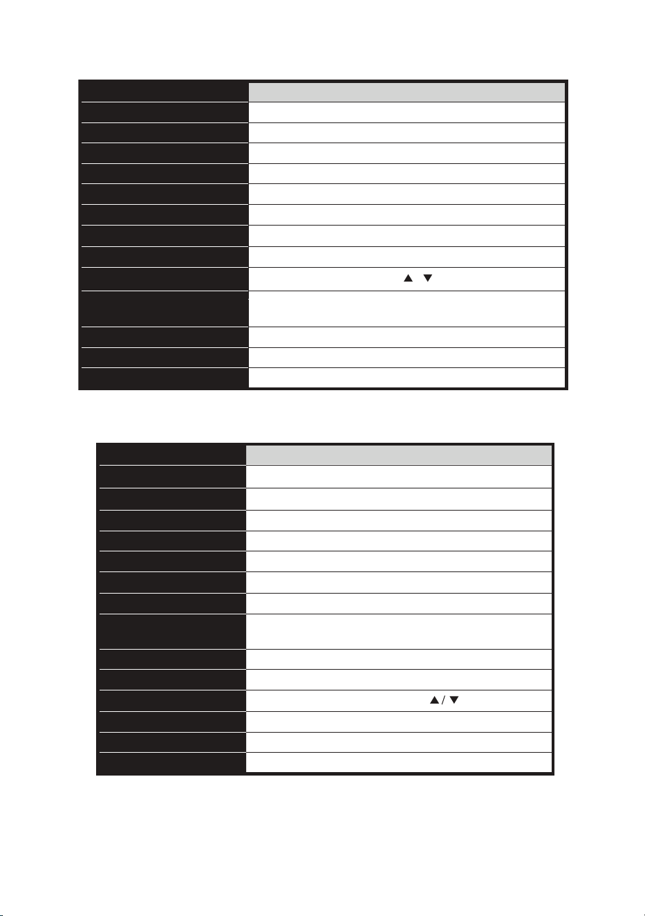
3-2 UHT8011 UHF PLL Hand Held Transmitter Microphone
MODEL
Frequency Mode
Phase-locked loop (PLL)
Frequency Range
470 ~ 960 MHz
Sync Frequency
Ultrasonic
RF Power Output
10m W / 50m W (as per local regulations)
RF Stability
< ± 10 kHz
ƌ
Fc
Modulation Frequency
± 48 kHz
Harmonic Radiation
< -50 dBc
Functions
Display
LCD + LED
Controls
channel, frequency
Battery
AA alkaline battery or NiMH rechargeable battery (x 2)
Charging
Yes
Dimensions
2” (W) x 10.5” (H)
MODEL
Frequency Mode
Phase-locked loop (PLL)
Frequency Range
470 ~ 960 MHz
Sync Frequency
Ultrasonic
RF Power Output
10m W /50 m W (as per local regulations)
RF Stability
< ± 10 kHz
ƌ
Fc
Modulation Frequency
± 48 kHz
Harmonic Radiation
< -50 dBc
Functions
Display
LCD + LED
Input
4-pin Mini XLR
Controls
Power, Mute, Set,
Battery
AA alkaline battery or NiMH rechargeable battery (x 2)
Charging
Yes
Dimensions
2.4” (W) x 3.8” (H) x 0.78” (L)
Mute, auto off, sensitivity adjustment, group,
UHT
8011
UBP
8011
Mute, auto off, sensitivity adjustment,
input level attenuation, group, channel, frequency
Power, Mute, Set, / , Button Lock
MODEL
Frequency Mode
Phase-locked loop (PLL)
Frequency Range
470 ~ 960 MHz
Sync Frequency
Ultrasonic
RF Power Output
10m W / 50m W (as per local regulations)
RF Stability
< ± 10 kHz
ƌ
Fc
Modulation Frequency
± 48 kHz
Harmonic Radiation
< -50 dBc
Functions
Display
LCD + LED
Controls
channel, frequency
Battery
AA alkaline battery or NiMH rechargeable battery (x 2)
Charging
Yes
Dimensions
2” (W) x 10.5” (H)
MODEL
Frequency Mode
Phase-locked loop (PLL)
Frequency Range
470 ~ 960 MHz
Sync Frequency
Ultrasonic
RF Power Output
10m W /50 m W (as per local regulations)
RF Stability
< ± 10 kHz
ƌ
Fc
Modulation Frequency
± 48 kHz
Harmonic Radiation
< -50 dBc
Functions
Display
LCD + LED
Input
4-pin Mini XLR
Controls
Power, Mute, Set,
Battery
AA alkaline battery or NiMH rechargeable battery (x 2)
Charging
Yes
Dimensions
2.4” (W) x 3.8” (H) x 0.78” (L)
Mute, auto off, sensitivity adjustment, group,
UHT
8011
UBP
8011
Mute, auto off, sensitivity adjustment,
input level attenuation, group, channel, frequency
Power, Mute, Set, / , Button Lock
3-3 UBP8011 UHF PLL Body Pack Transmitter
4
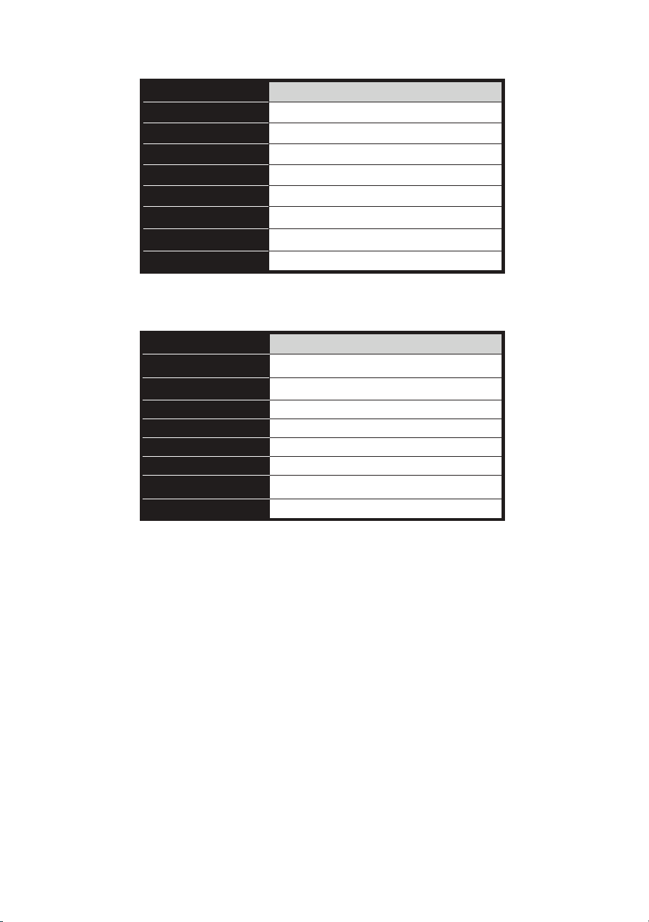
3-4 BCLM1 Lavalier Microphone
MODEL
Connector
4P Mini XLR
Frequency Response
100 ~ 15,000 Hz
Polar Pattern
Cardioid
Sensitivity (at 1000Hz) -60 ± 3 dB*
Impedance
2.2k Ω
Max. SPL for 1% THD
130 dB
Dimensions
Ø 0.39” (W) x 1” (H)
Net Weight 0.75 oz.
MODEL
Connectors
4P Mini XLR
Frequency Response
100 ~ 18,000 Hz
Polar Pattern Cardioid
Sensitivity (at 1000Hz) -65 ±3 dB*
Impedance 1.8 k Ω
Max. SPL for 1% THD 120 dB
Dimensions
4.9” (W) x 5.2” (H) x 6.2” (D)
Net Weight 0.63 oz. (cable excluded)
UHFHSMB
BCLM
1
*0dB = 10V/pa
*0dB = 10V/pa
3-5 UHFHSMB Headset Microphone
MODEL
Connector
4P Mini XLR
Frequency Response
100 ~ 15,000 Hz
Polar Pattern
Cardioid
Sensitivity (at 1000Hz) -60 ± 3 dB*
Impedance
2.2k Ω
Max. SPL for 1% THD
130 dB
Dimensions
Ø 0.39” (W) x 1” (H)
Net Weight 0.75 oz.
MODEL
Connectors
4P Mini XLR
Frequency Response
100 ~ 18,000 Hz
Polar Pattern Cardioid
Sensitivity (at 1000Hz) -65 ±3 dB*
Impedance 1.8 k Ω
Max. SPL for 1% THD 120 dB
Dimensions
4.9” (W) x 5.2” (H) x 6.2” (D)
Net Weight 0.63 oz. (cable excluded)
UHFHSMB
BCLM
1
*0dB = 10V/pa
*0dB = 10V/pa
UDR
8011
UHF PLL SINGLE CHANNEL
DIVERSITY RECEIVER
12
34
56
7
8
9
10 11 13
9
12
5
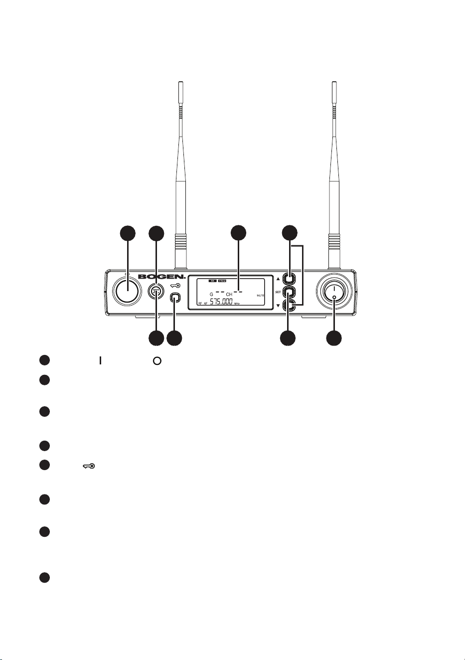
4. Description of Parts
4-1 UDR8011 Receiver Feature Callouts - Front View
1
4
2
5
3
6
7
8
POWER: = ON and = OFF
SET: Push and hold for 2 seconds to enter the Setting Mode. Push SET
to advance to the next parameter.
▲/▼: In the Setting Mode, push ▲/▼ to change the parameter value.
In the non-Setting Mode: push ▲/▼ to adjust audio output volume.
LCD Display: System Information (see page 7 for features).
LOCK : Push and hold for 2 seconds to lock the front panel buttons.
Repeat to unlock front panel buttons
SYNC: This allows you to pair the transmitter after modifying a parameter.
Push SYNC to synchronize the settings to the transmitter.
SYNC Indicator: This shows the current pairing status. It ashes rapidly when data
is being transmitted and the ashing stops when the synchronization is completed.
However, the ashing slows down if synchronization fails after a period of time.
Ultrasonic Sync Transmission Element: Transmits digital pairing data at ultra-
sonic frequency. When setting, direct line of sight is required between ultrasonic
elements of receiver & transmitter. The effective range is 30º on both sides off-axis
with the maximum distance of 12”.
6
UDR
8011
UHF PLL SINGLE CHANNEL
DIVERSITY RECEIVER
12
34
56
7
8
9
10 11 13
9
12
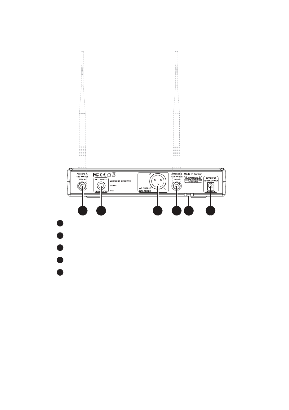
4-2 UDR8011 Receiver Feature Callouts - Rear View
9
12
10
11
RECEIVING ANTENNA: BNC connection for 1/2 antenna.
PHONE JACK (1/4” TS): Unbalanced audio output jack.
3P XLR MALE: Balanced audio output jack.
STRAIN RELIEF : Securement for DC power cable.
DC POWER SOCKET : 12-15 VDC / 300mA power supply.
13
y
7
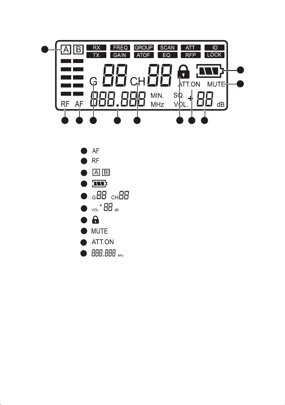
4-3 UDR8011 Receiver LCD Display
9
10
: Audio Signal strength
: RF Signal strength
: Antenna A or B active
: Transmitter Battery Level
: Group/Channel
: Volume Output
: Button Lock
: Receiver/Transmitter Mute
: Output Attenuation
: Frequency
Shown above in the non-Setting Mode
/
1
4
2
5
3
6
7
8
2324
25
26
27 2829
30
3132
12
3
4
5 67
8
910
27
5
8
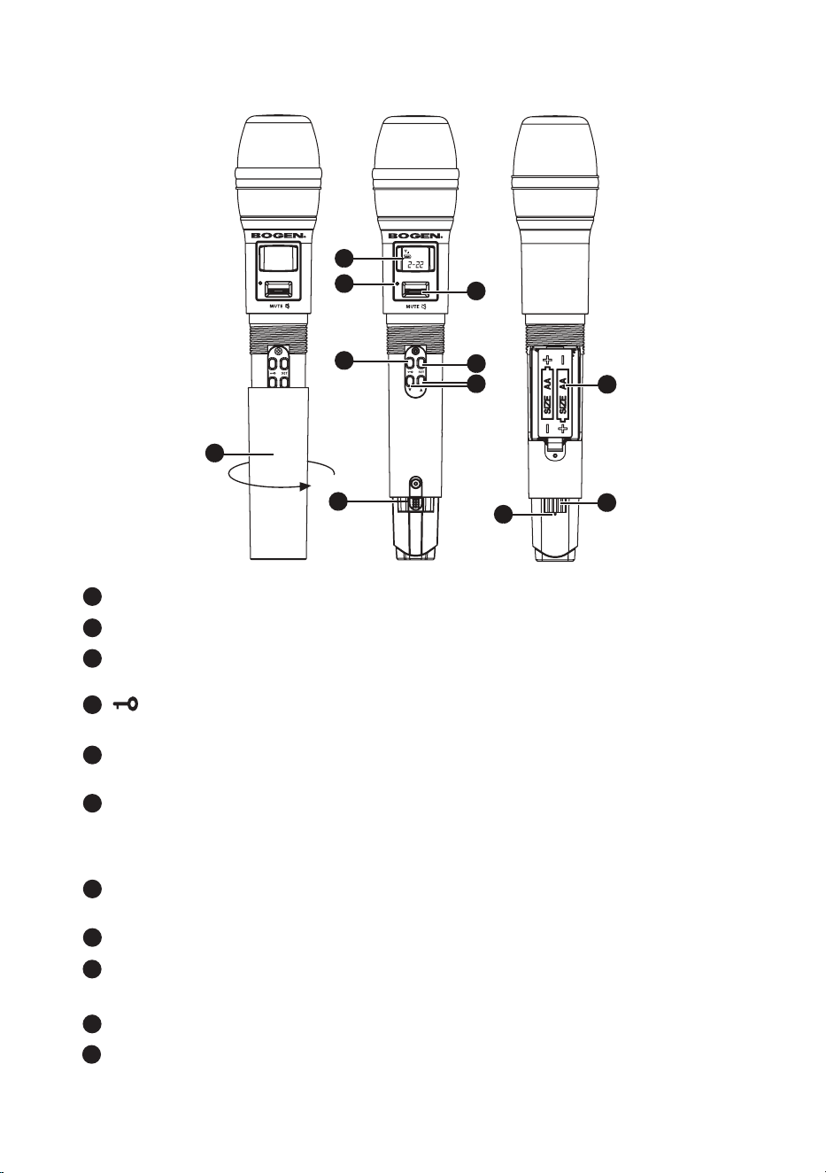
4-4 UHT8011 Hand Held Transmitter Feature Callouts
9
10
1
4
2
5
3
6
7
8
REMOVABLE HANDLE COVER: Unscrew to access controls and batteries.
LCD DISPLAY: Displays the parameter settings in the transmitter.
LED INDICATOR: Displays the transmitter’s status, including battery level,
mute and pairing indication.
: Push and hold button for 2 seconds to lock the buttons/controls. Push and
hold again for 2 seconds to unlock.
POWER: Push to turn the transmitter on. When the transmitter is on, push
and hold for 2 seconds to turn it off.
MUTE: When transmitter is on, slide switch UP to talk and DOWN to mute.
If the transmitter is off, slide switch UP to turn the unit on. The transmitter
turns off automatically after 1, 10, or 30 minutes of Mute mode, depending on
the parameter setting.
SET: Push and hold for 2 seconds to enter the Setting mode. Push SET to
advance to the next parameter.
▲/▼: In the Setting mode, push ▲/▼ to change the parameter value.
ULTRASONIC RECEIVING ELEMENT: Receives pairing signals from the
ultrasonic element at the receiver end.
BATTERY HOLDER: Holds AA 1.5V battery or rechargeable NiMH battery (x 2).
CHARGING CONTACT: If rechargeable batteries are used, this microphone
can be recharged with optional charger (UHFDCD).
UHT
8011
1
2
3
9
4
5
6
7
8
10
11
11
9
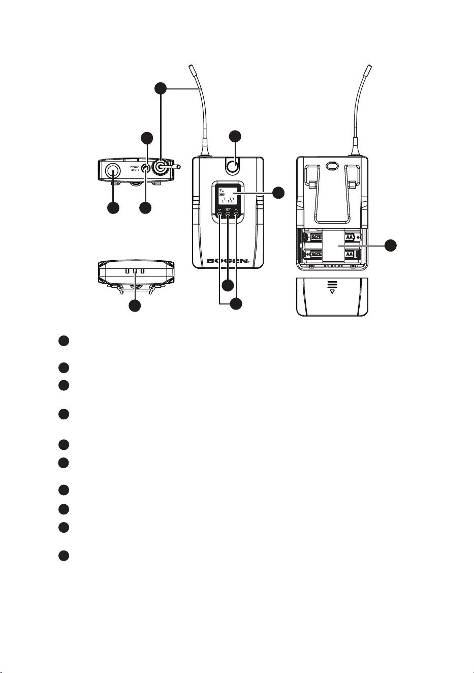
4-5 UBP8011 Body Pack Transmitter Feature Callouts
UHF PLL TRANSMITTER
UBP
8011
70
75
72
71
73
78
79
76
77
TOP VIEW
BOTTOM VIEW
FRONT
VIEW
REAR
VIEW
1
2
3
4
6
7
8
9
10
74
5
LED INDICATOR: Indicates the transmitter’s status, including battery level,
mute and pairing indication.
MICROPHONE INPUT PORT: 4P mini XLR jack
MUTE/POWER: Push once to turn the unit on. While the unit is on, push once
to mute and push again to unmute. Push and hold for 2 seconds to turn off.
CHARGING CONTACT: If rechargeable batteries are used, this transmitter
can be recharged with an optional charger (UHFDCD).
ANTENNA: The antenna of transmitter
ULTRASONIC RECEIVING ELEMENT: It receives the pairing signals from
the ultrasonic transmission unit at the receiver end.
LCD DISPLAY: Displays the parameter settings in the transmitter.
▲/▼: In the Setting mode, push ▲/▼ to change the parameter value.
SET: Push and hold for 2 seconds to enter the Setting mode. Push SET to
advance to the next parameter.
BATTERY HOLDER: Holds AA 1.5V battery or rechargeable NiMH battery (x 2).
9
10
1
4
2
5
3
6
7
8
10
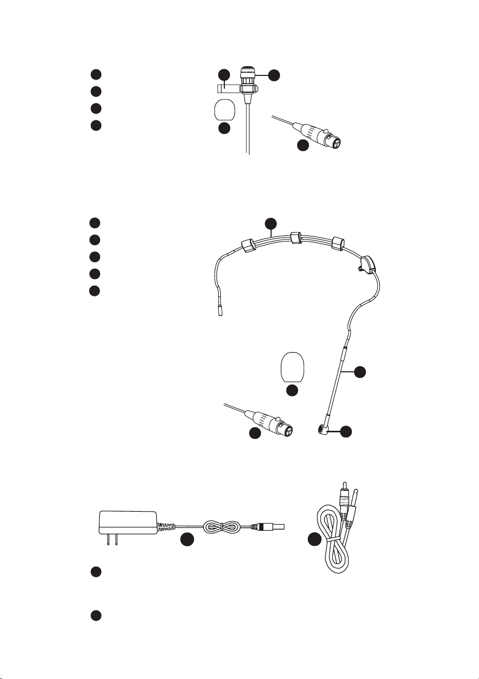
AC/DC ADAPTOR (UDR8011-RPS):
AC IN: AC100~240V, 50/60Hz
DC OUT: DC12V/0.5A
AF OUTPUT CABLE: (with 1/4” plug to RCA plug ends)
4-6 BCLM1 Condenser Lavalier Microphone (Standard with UBP8011)
84
82
1
3
BCLM
1
84
1
2
84
4
82
1
84
2
84
4
84
5
84
3
84
2
MIC CLIP
MICROPHONE
WINDSCREEN
4-PIN MINI XLR
1
2
4-8 Included Accessories
84
82
1
3
BCLM
1
84
1
2
84
4
82
1
84
2
84
4
84
5
84
3
84
2
3
4
4-7 UHFHSMB Headset Microphone (optional for UBP8011)
84
82
1
3
BCLM
1
84
1
2
84
4
82
1
84
2
84
4
84
5
84
3
84
2
ADJUSTABLE HEADBAND
GOOSENECK
MICROPHONE
WINDSCREEN
4-PIN MINI XLR
1
2
3
4
5
1
2
11
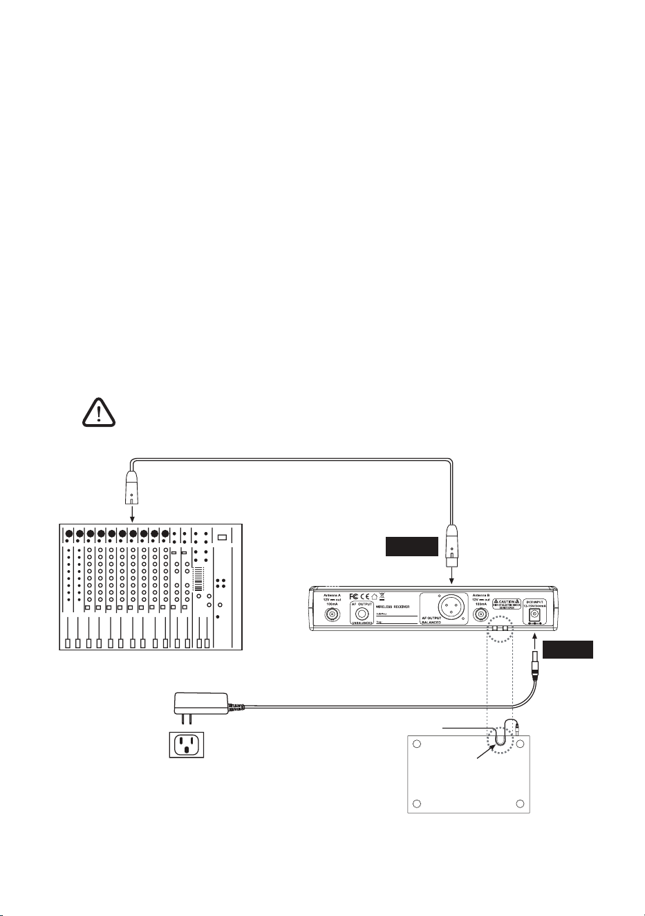
5. Connecting
1.1 UDR8011 Receiver
The XLR balanced output jack or 1/4” unbalanced output jack can
be used to connect the audio output to a mixer or an amplier.
1. Connect the audio output of receiver to mixer or amplier
2.1. Connect the AC/DC adapter:
Check that the DC current and voltage ratings of the adapter match
the label on the unit. Connect the DC terminal to the DC input port
on the unit and the AC end to an AC outlet.
2.2. Set the parameters:
Turn the power on and set the parameters of the receiver according
to the instructions (section 6.1).
CAUTION! Secure the power cable on the strain relief fastening hook
to prevent the power cable from accidental removal.
2. Connect the Power
5-1 How to Connect the UDR8011 Receiver
AC/DC Adapter
STEP 1
Wall
Outlet
Mixer/Amplifier
STEP 2
UDR
8011
Strain Relief:
Power cable
fastening hook
UDR8011
BOTTOM
VIEW
AC/DC Adapter Cable
12
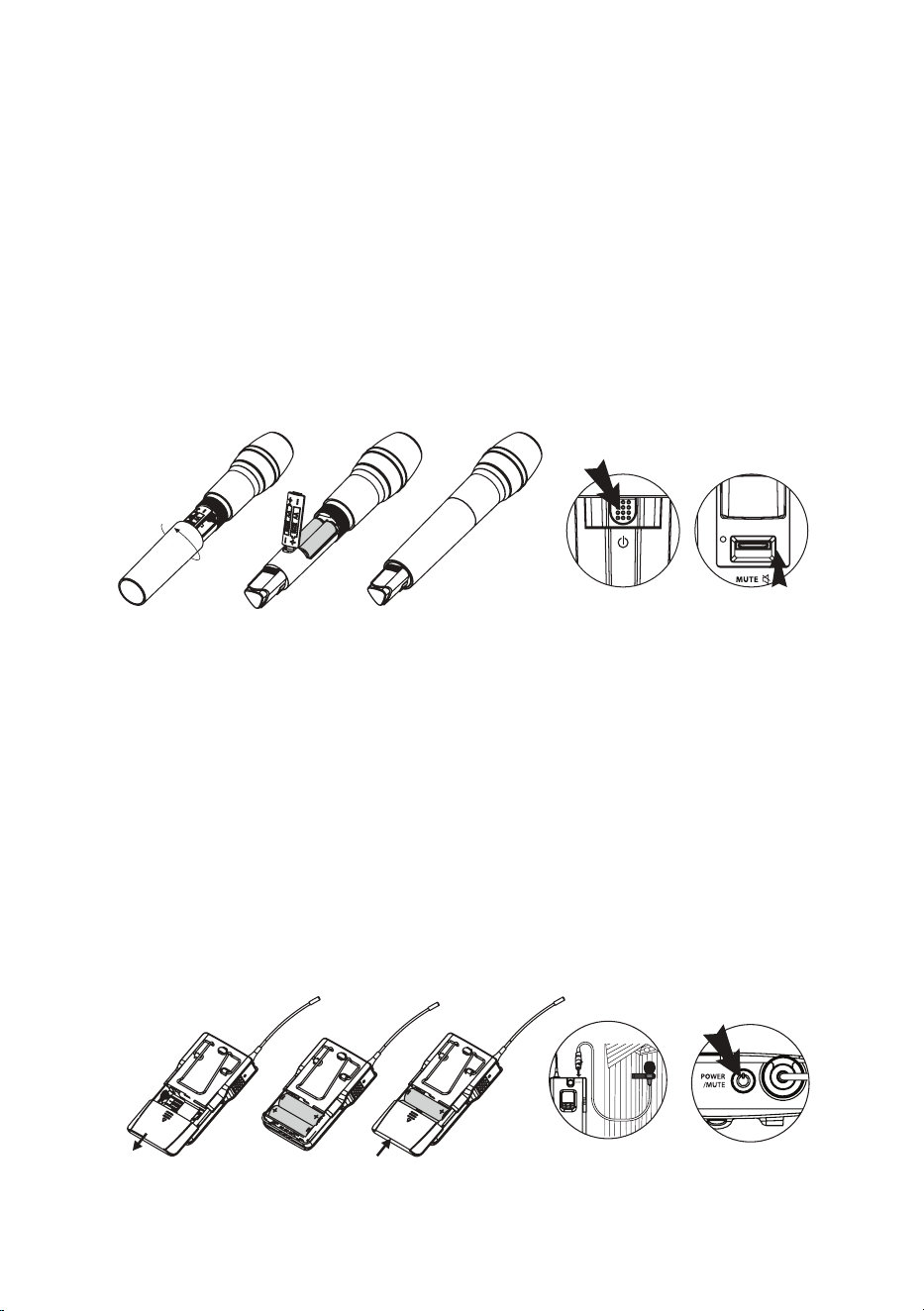
1. UHT8011 Hand Held Transmitter
5-2 Transmitter Installation
1. Unscrew the outer tube of the transmitter (Fig. 1).
2. Open panel door and place 2 AA batteries in the battery holder,
ensuring they are in the correct polarities (Fig. 2).
3. Screw the outer tube on (Fig. 3).
4. To turn the unit on:
a. Push the Power button to turn the unit on (Fig. 4a), or
b. Push the Mute switch up to turn the unit on (Fig. 4b).
5. Set the transmitter parameters according to the instructions
(section 6-2).
1. Slide the battery holder cover downwards (Fig. 1).
2. Place 2 AA batteries in the battery holder ensuring they are in the
correct polarities (Fig. 2).
3. Slide the battery holder cover upwards to close (Fig. 3)
4. Insert the microphone 4-pin mini XLR into the body pack jack (Fig. 4).
5. Push the Power button to turn the unit on (Fig. 5).
6. Set the transmitter parameters according to the instructions
(section 6-2).
2. UBP8011 Body Pack Transmitter
Fig. 1
Fig. 1
Fig. 2
Fig. 2
Fig. 3
Fig. 3 Fig. 4 Fig. 5
Fig. 4a Fig. 4b
Fig. 1
Fig. 1
Fig. 2
Fig. 2
Fig. 3
Fig. 3 Fig. 4 Fig. 5
Fig. 4a Fig. 4b
13
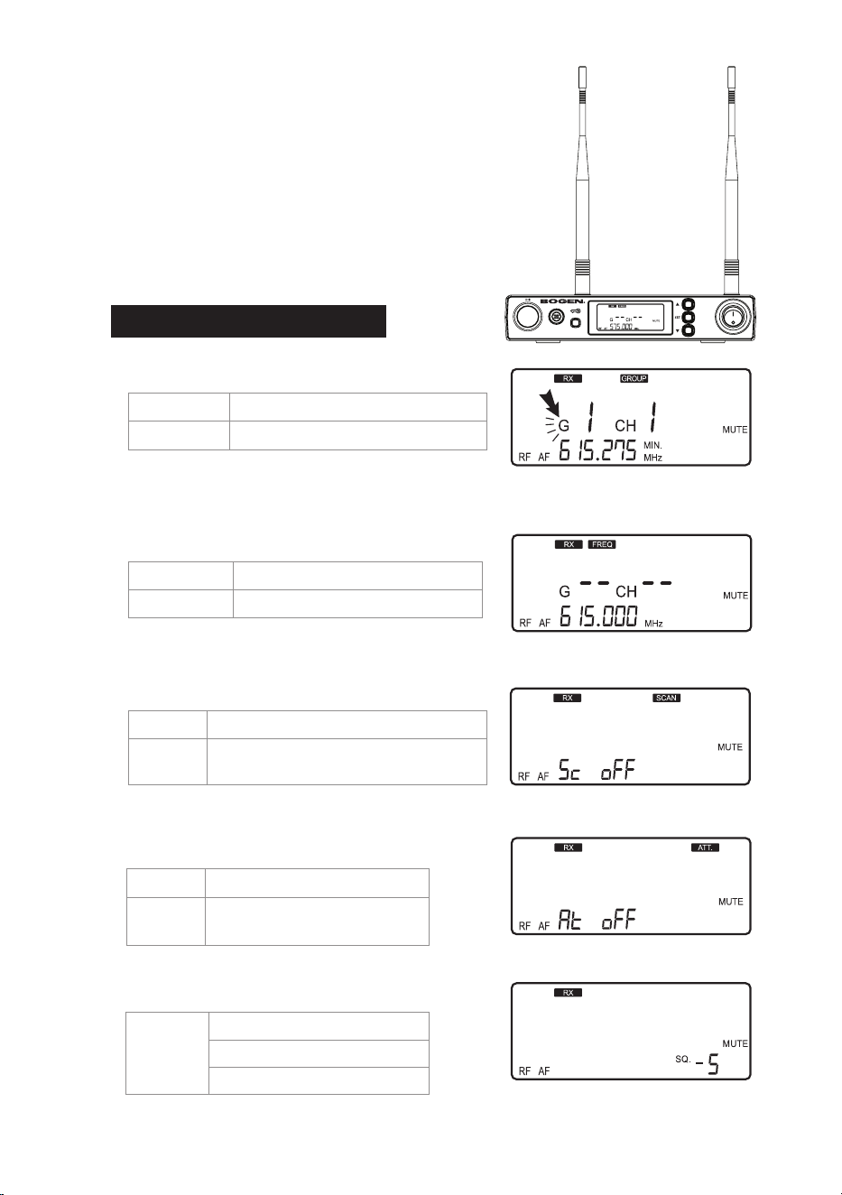
6. Instructions for Use
6-1 UDR8011 Receiver
1. Parameter Setting
Push and hold the SET button to enter the
Setting mode. Push the ▲/▼ button to select
parameter. Push SET again to advance to
the next parameter.
When RX receiver is selected:
◎ FREQ: Frequency Setting
In 1 MHz Select frequency with ▲/▼
In 0.025MHz
Select frequency with ▲/▼
Select the number of frequency rst
in MHz and then in 0.025 MHz.
◎ SCAN: Channel Scan
SC oFF
CH: Channel will increment sequentially.
SC on
CH: Channel will scan for the next avail-
able channel, avoiding interference.
This function is deactivated.
UHF PLL TRANSMITTER
UBP
8011
UDR
8011
UHF PLL SINGLE CHANNEL
DIVERSITY RECEIVER
The default setting is 0.
◎ ATT: Audio Output Attenuation (XLR)
At oFF
No attenuation at audio output
At on
20 dB attenuation at audio
ouput
This function is deactivated.
◎ SQ: Squelch Sensitivity
-5~+10dB -5 is the maximum sensitivity.
+10 is the minimum sensitivity.
The default setting is 0.
◎ GROUP: Group / Channel
G: group
Select default group 1~6
CH: channel
Select default channel, 1~22 (max.)
Select the group when G is ashing;
select the channel when CH is ashing.
Note: When Channel Scan is ON, ▲/▼ will scan
for the next available channel.
14
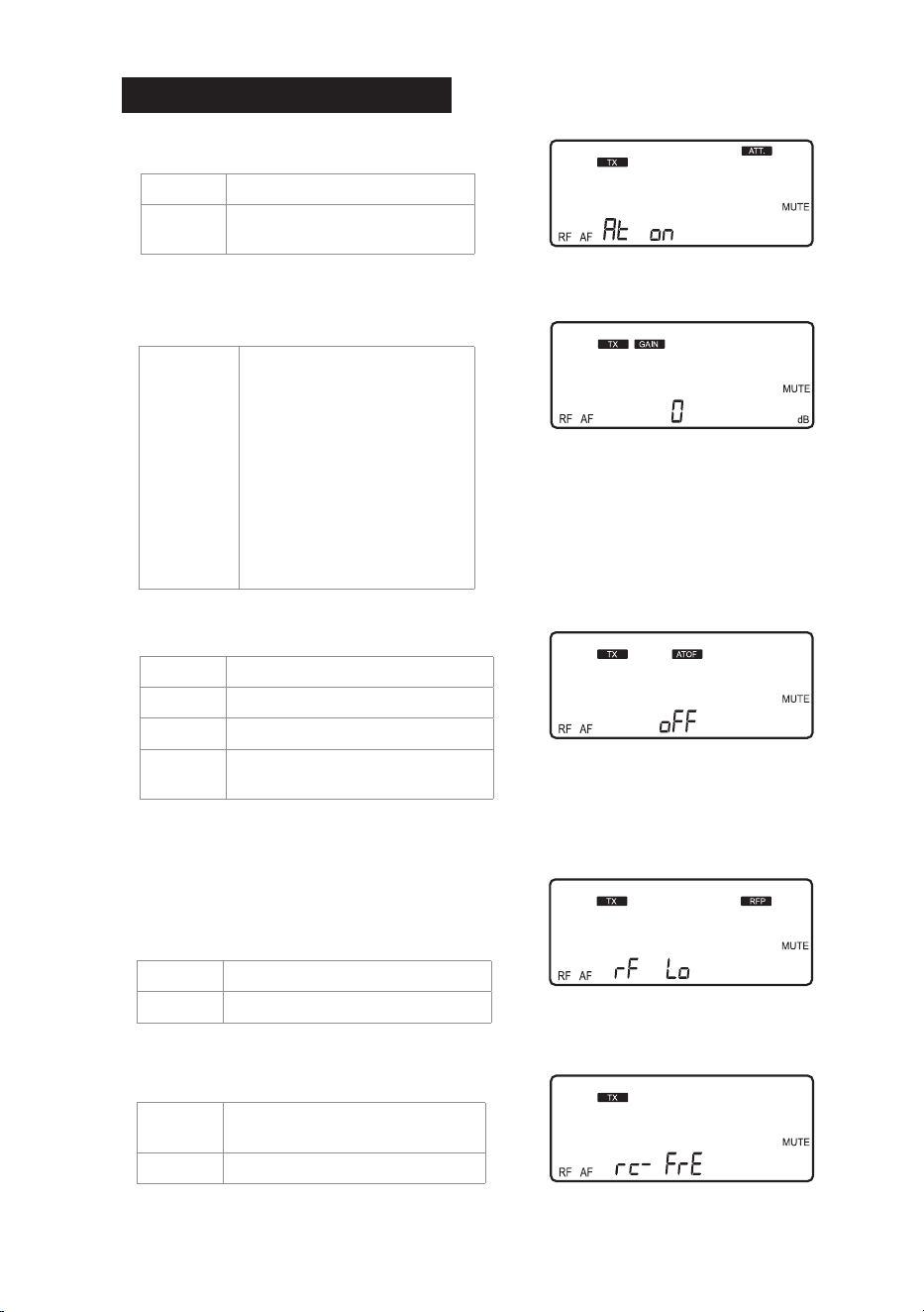
When TX transmitter is selected:
◎
ATT: Microphone Audio Input Attenuation
At oFF
No attenuation.
At on
20 dB attenuation at audio
input).
The function is activated with 20 dB
of audio input attenuation.
◎ GAIN: Microphone Input Sensitivity
High
Sensitivity
Default
Low
Sensitivity
GAIN: +15 dB
GAIN: +12 dB
GAIN: +9 dB
GAIN: +6 dB
GAIN: +3 dB
GAIN: 0 dB
GAIN: -3 dB
GAIN: -6 dB
GAIN: -9 dB
GAIN: -12 dB
GAIN: -15 dB
Shows the microphone input sensitivity
is now at 0 dB (default setting).
◎ ATOF: Automatic Turn Off Timer
AO OF
This function is deactivated.
AO 1
1 minute shutdown.
AO 10
10 minute shutdown.
AO 30
30 minute shutdown.
This function is deactivated.
When active, the transmitter will
shutdown only when in MUTE mode.
◎ RFP: RF Transmitter Power
rF Lo 10mW
rF Hi 50mW
The transmitter comes with 2 stages of RF
power output (as per local regulations).
Shows that the RF Output is LO (10mW)
The default setting is 10 minutes.
rC-FrE
Only frequency setting will be
synchronized
rC-ALL
All settings will be synchronized
◎ RC: (Resync Conguration)
The default setting is rC-FrE.
Only frequency setting will be
synchronized during pairing.
15
2. Volume Adjustment
In non-Setting Mode, adjust the volume from 0 to -31 dB using the ▲/▼button.
•
The minimum volume is -31 dB.
•
The maximum volume is 0 dB.
•
The default setting is -10 dB.
Note: This Volume affects the balanced
and unbalanced outputs
Minimum volume at -31 db;
maximum volume at 0dB
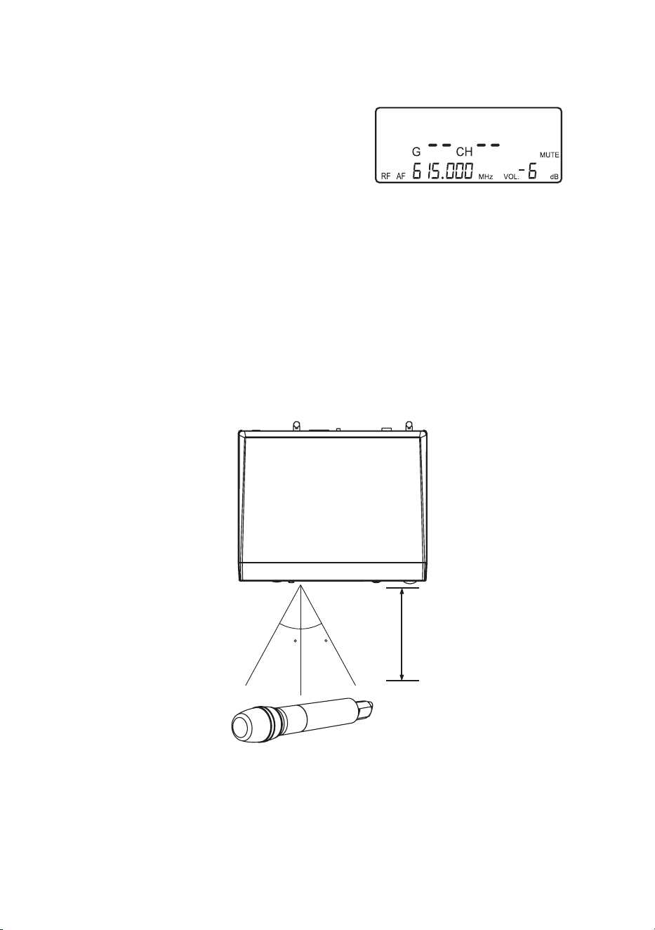
3. Sync Pairing
Once the parameters are set, push the SYNC button and the digital pairing
data will be sent to the transmitter via ultrasonic transmission for parameter
synchronization. The indicator will flash rapidly while the data is being
transmitted. When the synchronization is completed, the indicator will stop
ashing. If the signal is not received for a certain period of time, the indicator
will ash slowly to inform pairing failure (the slowly ashing indicator can be
reset by pushing any button).
Note: The best pairing distance is 12-inches, ±30º. Line of Sight is required.
+30
12-inches
-30
TOP VIEW
UDR8011
UHT8011
The Transmitter’s battery level is also shown on the LCD display. If the
battery level is ≤ 2V, the frame around the battery level will ash and the
backlight turns Red as a warning .
4. Battery Level
16
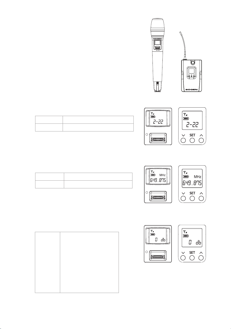
6-2 UHT8011 Hand Held Transmitter
and the UBP8011 Body Pack
Transmitter
1. Parameter Setting
Push and hold the SET button to enter the
Setting mode. Push the ▲/▼ button to select
parameter. Push SET again to advance to
the next parameter.
UHF PLL TRANSMITTER
UBP
8011
UDR
8011
UHF PLL SINGLE CHANNEL
DIVERSITY RECEIVER
UHF PLL TRANSMITTER
UBP
8011
UDR
8011
UHF PLL SINGLE CHANNEL
DIVERSITY RECEIVER
Select the number of frequency
rst in MHz and then in 0.025 MHz.
UHT8011 UBP8011
Select the number for group and
then the number for channel.
◎ FREQ: Frequency Setting
In 1MHz Select frequency with ▲/▼
In 0.025MHz
Select frequency with ▲/▼
◎ GROUP: Group / Channel
G: group
Select default group 1~6
CH: channel
Select default channel, 1~22 max.
◎ GAIN: Microphone Input Sensitivity
Sensitivity set at GAIN 0 dB
(default setting).
High
Sensitivity
Default
Low
Sensitivity
GAIN: +15 dB
GAIN: +12 dB
GAIN: +9 dB
GAIN: +6 dB
GAIN: +3 dB
GAIN: 0 dB
GAIN: -3 dB
GAIN: -6 dB
GAIN: -9 dB
GAIN: -12 dB
GAIN: -15 dB
17
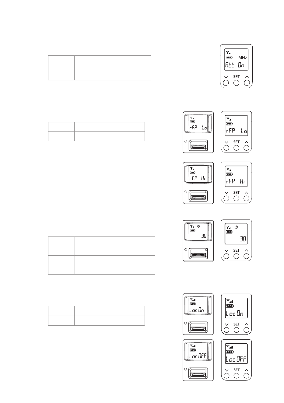
◎ RFP: RF Transmitter Power
rFP Lo
10mW
rFP Hi
50mW
The RF output is LO.
The RF output is Hi.
◎ ATOF: Automatic Turn Off Timer
OFF
This function is deactivated.
1
1 minute shutdown.
10
10 minute shutdown.
30
30 minute shutdown.
◎ Key Lock
Loc on
Lock ON
Loc oFF
Lock OFF
(The default setting is 10 minutes)
UHT8011 UBP8011
Audio input
attenuation at 20 dB.
◎
ATT: Microphone Audio Input Attenuation
At oFF
No attenuation.
At on
20 dB attenuation at audio
input).
UHT8011 UBP8011
When active, the transmitter will
shutdown only when in MUTE mode.
Note: When Lock is ON, push and hold SET
button for 2 seconds to enter Lock Disable.

18
7. Additional Product Instructions
1. For the best Sync results, always keep the UHT8011/UBP8011 transmitter within
12-inches of the UDR8011 receiver with Line of Sight.
2. The UDR8011 receiver and UHT8011/UBP8011 transmitter must be away from
other metal objects, preferably 20-inches or farther.
3. It is recommended to hold the UHT8011 transmitter (microphone) at the
mid-section for the best signal.
4. If the UHT8011/UBP8011 transmitters will not be in use for an extended period
of time, the batteries should be removed from the battery holder.
5. For the best power performance, it is recommended to change both batteries.
19
8. Wireless System Frequency List

9. Product Warranty
The Bogen UHF Wireless Systems (UHF8011-BP/HH) are warranted to be free from de-
fects in material and workmanship for one (1) year from the date of sale to the original pur-
chaser. Any part of the product covered by this warranty that, with normal installation and use,
becomes defective (as conrmed by Bogen upon inspection) during the applicable warranty
period will be repaired or replaced by Bogen, at Bogen’s option, provided the product is shipped
insured and prepaid to: Bogen Factory Service Department, 4570 Shelby Air Drive, Suite 11,
Memphis, TN 38118 USA. Repaired or replacement product(s) will be returned to you freight
prepaid. This warranty does not extend to any of our products that have been subjected to abuse,
misuse, improper storage, neglect, accident, improper installation or have been modied or
repaired or altered in any manner whatsoever, or where the serial number or date code has been
removed or defaced.
THE FOREGOING LIMITED WARRANTY IS BOGEN’S SOLE AND EXCLUSIVE WARRANTY
AND THE PURCHASER’S SOLE AND EXCLUSIVE REMEDY. BOGEN MAKES NO OTHER
WARRANTIES OF ANY KIND, EITHER EXPRESS OR IMPLIED, AND ALL IMPLIED WARRAN-
TIES OF MERCHANTABILITY OR FITNESS FOR A PARTICULAR PURPOSE ARE HEREBY
DISCLAIMED AND EXCLUDED TO THE MAXIMUM EXTENT ALLOWABLE BY LAW. Bogen’s
liability arising out of the manufacture, sale or supplying of products or their use or disposition,
whether based upon warranty, contract, tort or otherwise, shall be limited to the price of the
product. IN NO EVENT SHALL BOGEN BE LIABLE FOR SPECIAL, INCIDENTAL OR CON-
SEQUENTIAL DAMAGES (INCLUDING, BUT NOT LIMITED TO, LOSS OF PROFITS, LOSS
OF DATA OR LOSS OF USE DAMAGES) ARISING OUT OF THE MANUFACTURE, SALE OR
SUPPLYING OF PRODUCTS, EVEN IF BOGEN HAS BEEN ADVISED OF THE POSSIBILITY
OF SUCH DAMAGES OR LOSSES. Some States do not allow the exclusion or limitation of
incidental or consequential damages, so the above limitation or exclusion may not apply to you.
This warranty gives you specic legal rights, and you may also have other rights which vary from
State to State.
Products that are out of warranty will also be repaired by the Bogen Factory Service Department–
same address as above or call 201-934-8500. Returned products which do not qualify for warranty
service, may be repaired or replaced at Bogen’s option with previously repaired or refurbished
items. The parts and labor involved in these repairs are warranted for 90 days when repaired by
the Bogen Factory Service Department. All parts and labor charges as well as shipping charges
will be at the owner’s expense.
All returns require a Return Authorization number. For most efcient warranty or repair service,
please include a description of the failure.
10/2018
Limited Warranty: Exclusion of Certain Damages
20
www.bogen.com
UHF PLL TRANSMITTER
UBP
8011
UDR
8011
UHF PLL SINGLE CHANNEL
DIVERSITY RECEIVER
UHF8011BP/HH
UDR8011 UBP8011UHT8011
UHF PLL SINGLE CHANNEL DIVERSITY WIRELESS SYSTEM