

About this Document
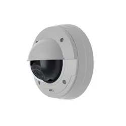
This manual is intended for administrators and users of the AXIS
P3364–VE Fixed Dome Network Camera, and is applicable to firmware
5.40 and later. It includes instructions for using and managing the
product on your network. Previous ex perience of networking will be of
use when using this product. Some knowledge of UNIX or Linux-based
systems may also be beneficial, for de veloping shell scripts and
applications. Later versions of this document will be pos ted to the Axis
website, as required. See a lso the product’s on line help, available via
the web- based interface.
Liability
Every care has been taken in the preparation of this manual. Please
inform your local Axis office of any inaccuracies or omissions. Axis
Communications AB cannot be held responsible for any technical or
typographical errors and reserves the right to make changes to the
product and manuals without prior notice. Axis Communications AB
makes no warranty of any kind with regard to the material contained
within this document, including, b ut not lim ited to, the implied
warranties of merchanta bility and fitness for a partic ular purpose. Axis
Communications AB shall not be liable nor responsible for incide ntal or
consequential damages in connection with the furnishing, performance
or use of this material. This product is only to be used for its intended
purpose.
Intellectual Property Rights
Axis AB has intellectual property rights relating to technology embo died
in the product described in this document. In particular, and without
limitation, th ese intellectual property rights may include one or more
of the patents listed at http://www.axis.com /pa tent.htm a nd one or
more additional patents or pending pa tent applications in the U S a nd
other countries.
This product contains licensed thir d-party software. See the menu item
“About” in the product’s user interface for more information.
This product contains source code copyright Apple Computer,
Inc.,underthetermsofApplePublicSourceLicense2.0(see
http://www.opensource.ap ple.com/apsl). The source code is available
from http://developer.apple.co m/darwin/p rojects/bonjour/
Equipment M odifications
This equipment must be installed and u sed in strict accordance with the
instructions given in the user documentation. This equipment contains
no user-serviceable compo nents. Unauthorized equipment ch anges or
modifications will invalida t e all applicable regu latory certifications
and approvals.
Trademark Acknowledgments
Apple, Boa, Bonjour, Ethernet, Internet Explorer, Linux , Microso
ft,
Mozilla, Real, SM PTE , Q ui ckTi me, UNIX, Windows, W in dows Vista and
WWW are registered trademarks of the respective holders. Java and
all Java-based trademarks and logos are trademarks or registe
red
trademarks of Oracle and/or its affiliates. UPnP
TM
is a certification
mark of the UPnP
TM
Implementers Corporation.
Support
Should you require any technical assistance, please contact your Axis
reseller. If your questions cannot be answered immediately, your
reseller will forward your queries throu
gh the appropriate channels to
ensure a rapid response. If you are connected to the Internet, you can:
• download user documentation and software updates
• find answers to resolved problems in the FAQ database. Search
by product, category, or phrase
• report p roblems to Axis support staff by logging in to your private
support area
• chat with Axis support staff (selected countries only)
• visit Axis Support at www.axis.com/techsup/
Electromagnetic Com patibility (EMC)
This equipment has been designe d and tested to fulfill applicable
standards for:
• Radio frequency emiss
ion when install ed according to the
instructions and used in its intended environment.
• Immunity to electrical and elect romagnetic phenomena when
installed accor
ding to the instructions and used in its intended
environment.
USA
This equipment has been tested using a shielded network cable (STP)
and found to com p ly with the limits for a Class B digital device,
pursuant to part 15 of the FCC Rules . These limits are designed
to provide reasonable protection against harmful interference in a
residential i nstallation. This equipment generates, uses and can radiate
radio frequency energy and, if not installed and used in accordance
with the instructions, m ay cause harmful i nterference to radio
communications. However, there is n o guarantee that interference
will not occur in a particular installation. If this equipment does
cause harmful interference to radio or television reception, which
can be determined by turning the equipment off and on, the user is
encouraged to try to correct the interference by one or more of the
following measures:
• Reorient or relocate the receiving antenna.
• Increase the separatio n between the equipment and receiver.
• Connect the equipment in to an outlet on a c ircuit different from
that to which the receiver is connected.
• Consult the dealer or an experienced radio/TV technician for help
Canada
This Class B digital apparatus complies with Canad ia n ICES-003.
This product fulfills the req uireme nts for imm u nity according to
EN 61000-6-1 residential, commercial and light-industry environments.
This product fulfills the req uireme nts for imm u nity according to
EN 61000-6-2 industrial environments.
This product fulfills the req uireme nts for imm u nity according to
EN 55024 office and com mercial environments.
Australia/New Zealand
This digital equipme nt fulfills th e requirements for RF emission
according to the C lass B limit of AS/NZS CISPR 22.
Japan
この装置は、クラスB 情報技術装置です。この装置は、家庭
環境で使用することを目 的としていますが、この装置がラジ
オやテレビジョン受信機に近接して使用されると、 受信障
害を引き起こすことがあります。 取扱説明書に従って正し
い取り扱いをして下さい。
Photobiological Safety
This product fulfills the requirements for photobiological s afety
according to EN 62471.

AXIS P3364–VE
Table of Contents
HardwareOverview .......................................... 4
Connectors .................................................... 4
LEDIndicators .................................................. 5
AccessingtheProduct ....................................... 7
AccessfromaBrowser ........................................... 7
AccessfromtheInternet .......................................... 8
SettheRootPassword ........................................... 8
TheLiveViewPage .............................................. 9
MediaStreams ............................................. 12
HowtoStreamH.264 ............................................ 12
MJPEG ........................................................ 12
AXISMediaControl(AMC) ........................................ 12
AlternativeMethodsofAccessingtheVideoStream .................... 13
AccessingAudioStreams ......................................... 14
SettingUptheProduct ...................................... 15
BasicSetup .................................................... 15
VideoandAudio ............................................ 16
VideoStream ................................................... 16
Stream Pro fi les ................................................. 17
CameraSettings ................................................ 17
ViewArea ..................................................... 19
Overlay ........................................................ 20
PrivacyMask ................................................... 21
Focus & Zoom . . . . . . . . . . . . . . . . . . . . . . . . . . . . . . . . . . . . . . . . . . . . . . . . . . 21
AudioSettings .................................................. 22
AudioClips .................................................... 23
Live View Config ............................................ 24
PTZ(PanTiltZoom) ......................................... 26
PresetPositions ................................................. 26
GuardTour ..................................................... 26
Advanced ...................................................... 27
Detectors .................................................. 28
CameraTampering .............................................. 28
MotionDetection ............................................... 28
AudioDetection ................................................ 30
Applications ............................................... 31
Events .................................................... 32
SettingUpanActionRule ........................................ 33
Recipients ..................................................... 34
Schedules ...................................................... 34
Recurrenc
es ....................................................
35
Recordings ................................................. 36
RecordingList .................................................. 36
ContinuousRecording ............................................ 36
SystemOptions ............................................. 38
Security ....................................................... 38
Date&Time .................................................... 41
Network ....................................................... 42
Storage ....................................................... 46
Ports&Devices ................................................. 47
Maintenance ................................................... 48
Support ....................................................... 48
Advanced ...................................................... 49
ResettoFactoryDefaultSettings ................................... 49
Troubleshooting ............................................ 51
CheckingtheFirmware ........................................... 51
UpgradingtheFirmware .......................................... 51
EmergencyRecoveryProcedure .................................... 51
Symptoms,PossibleCausesandRemedialActions ..................... 52
Technical Specifications ...................................... 56
PerformanceConsiderations ....................................... 58
3

AXIS P3364–VE
Hardware Overview
Hardware Overview
10 11 12
2
1
3 4 5 6 7
8 9
14
13
1.
Camera unit
2.
Network connector (PoE)
3.
Audio o ut
4.
LED connectors
5.
Audio in
6.
I/O connector
7.
Control button
8.
Fan output connector
9.
SD memory card slot
10.
Mounting bracket
11.
Network cable
12.
Unit casing
13.
Serial number
14.
Heater
CAUTION
The heater m ay be hot!
Connectors
For technical specifications, see
page 56
.
Network connector - RJ-45 Ethernet connector. Supp orts P ower over Ethernet (PoE).
4

AXIS P3364–VE
Hardware Overview
NOTICE
Due to local regulations or the environmental and electrical conditions in which the p roduct is to be used, a shielded
network cable (STP) may be appropriate or req uired. Any network cab les that are routed in outdoor environments or similar
shall be shielded (STP) and intended for their specific use. Make sure that the network switch is properly grounded. See
Electromagnetic Compatibility (EM C )
for regulatory requirements.
Audio in (pink) - 3.5 mm input for a m ono microphone, or a line-in mono signal (left channel is used from a stereo signal).
Audio out (green) - 3.5 mm output for audio (line level) that can be connected to a public address (PA) system or a n active speaker
with a built-in amplifier. A stereo connector must be used for audio out.
SD card slot - A standard or h igh-capacity SD card (not included) can be used for local recording with removable storage.
NOTICE
To p revent corruption of recordings, the SD card should be unmounted before removal. To unmount, go to Setup > System
Options > Storage > SD Card a n d click Unmount.
Control button - The control button is used for:
• ConnectingtoanAXISVideoHostingSystemservice.See
page 42
. To connect, press and hold the button for about
1 second until the Status LE D flashes gr een .
• ConnectingtoAXISInternetDynamicDNSService. See
page 43
. To connect, press and hold the button for
about 3 seconds.
• Resetting the p rod uct to fa ctory default settings. See
page 49
.
I/O terminal connector - Use in applications for e.g. m otion detection, event triggering, time lapse r ecording and alarm notifications.
In addition to an auxili ary pow e r and a GND pin, the I/O terminal connector pro v ides the interface to:
• Digital output — For connecting externa l devices such as relays and LEDs. Connected devices can be activated by
the VAPIX® Application Programming Interface, output b uttons on the Live View page or by an Actio n Rule. The
output will show as active (shown under System Options > Ports & Devices) if the alarm device is activated.
• Digital input — An alarm input for connecting devices that can toggle between an open a nd closed circuit, for
example: PIRs, door/window contacts, glass break detectors, etc. When a signal is received the state chan ges and
the input becomes active (shown under System Options > Ports & Devices).
LED Indicators
LED
Color
Indication
Green
Steady for connection to a 100 MBit/s network. Flashes for network activity.
Amber
Steady for connection to a 10 MBit/s network. Flashes for network activity.
Network
Unlit No network connecti
on.
Green Steady g reen for normal operation.
Amber
Steady during startup and when restoring settings.
Status
Red
Sl
ow flash for failed upgrade.
Green
Normal operation.
Power
Amber
Flashes green/amber during firmware upgrade.
5

AXIS P3364–VE
Hardware Overview
Note
• The Status LED can be configured to be unlit during normal operation. To configure, go to Setup > System Options >Ports
& Devices >LED. See the online help for more infor m ation.
• The Status LED can be configured to flash while an event is a ctive.
• The S tatus LED can be configured to flash for identifying the unit. This can be done under Setup > System O ptions >
Maintenance.
6

AXIS P3364–VE
Accessing the Product
Accessing the Product
To install the Axis product, refer to the Installation G uide supplied with the prod uct.
The product can be used with most operating systems and browsers. The recommended browsers are Internet Ex plore r with Windows,
Safari with Macintosh and Firefox with other operating systems. See
Technical Specificatio n s, on page 56
.Toviewstreamingvideoin
Internet Exp lore r, allow install ation of AXI S Media Control (AM C ) when prompted.
Note
• Q uickTime
TM
is also supported for viewing H.264 streams and for audio.
• If your computer restricts the use of additional software components, the product can be configured to use a Java
applet for viewing Motion JPEG.
Access from a Browser
1. Start a browser (Internet Explorer, Firefox, Safari).
2. Enter the IP address or host name of the Axis product in the browser’s Location/Address field. To access the product from a
Macintosh co mputer (Mac OS X), click on the Bonjour tab and select the product from the drop-down list.
If you do not know the IP address, use AXIS IP U tility to locate the product on the network. For more inf orm a tion on how to
discover and assign an IP address, refer to the Installation Guide.
3. Enter your user name and p assword. If this is the first tim e the product is accessed , the root pas sw ord must first be
configured; for instructions see
Set the Root Password, on page 8
.
4. The product’s Live View page appears in your browser.
Note
The controls and layout of the Live View page may have been customized to m e et specific installation requirements and
user preferences. Consequently, some of the examples and functions featured here may differ from t hose displayed in
your own Live View page.
7

AXIS P3364–VE
Accessing the Product
Access from the Internet
Once connected, the Axis product is accessible o n your local network (LAN). To access the product from the Internet you must
configure your network router to allow incoming data traffic to the product. To do this, enable the NA T-trave rs al feature, which
will attempt to automatically co n fi gure the router to allow access to the prod uct. This is e n able d from Setup > System O ptions >
Network > TCP/IP A d va n ced.
For mo re information, please s ee
NAT traversal (port mapping) for IPv4, on page 44
. See also AXIS Internet Dynamic DNS Service at
www.axiscam.net For T echnical notes on this and other t opics, visit the Axis Support web at www.axis.com/techsup
Set the Root Password
To gain access to the Axis product, you must set the password for the d efault administrator user root. This is done in the Configure
Root Password dialog, which appears w hen the product is accessed for the first time.
To prevent network eavesdropping, the root password can be set via an encrypted H TTPS connection, which requires an HTTPS
certificate. HTTPS (Hypertext Transfer Protocol over SSL ) is a protocol used to encrypt traffic between web browsers and servers. The
HTTPS certificate ensures encrypted exchange of information.
To set the password via a standard HTTP connection, enter it directly in the first dialog.
To set the password via an encrypted HTTPS connection, follow these steps:
1. Click Create self-signed certificate.
2. Provide the requ ested information and click OK .Thecertifi ca te is created and the passwo rd can now be set securely. A ll
traffic to and from the product is encrypted from this point on.
3. Enter a password and then re-enter to confirm the spelling. Click OK. The password has now been configured.
Note
• The default administrator user name root is permanent and cannot be deleted.
• If the password for root is lost, the product must be reset to the factory default settings. See
Reset to Factory Default
Settings, on page 49
.
Set Power Line Frequency
Power line frequency is set the first time the Axis product is a cces sed and can only be changed from Plain Config(see
page 49
)
or by resetting the product to factory default.
8

AXIS P3364–VE
Accessing the Product
Select the power line frequency (50 H z or 60 Hz) used at the location o f the Axis product. Selecting the wrong frequency may cause
image flickeriftheproductisusedinfluorescent light environments.
When using 5 0 Hz, the maximum frame rate is limite d to 25 fps.
Note
Power line frequency is different in differe nt geographic regions. In the Americas, 60 Hz is usually used; most other parts of
the world use 5 0 Hz. Local variatio n s m ay apply, always check with the local authorities.
TheLiveViewPage
The controls and layout of the Live View page may have been customized to meet specific installation requirements and user
preferences. Consequently, some of the examples and functions featured here may differ from those displayed in your own Live View
page. The following provides an overview of each available control.
Controls on the Live Vi e w Page
Click View size to scale the image down to 800 pixels wide or to full scale. Only ava ilable i n M JPEG .
The Stream Profile drop-down list allows yo u to select a customized or pre-pro g ram m ed stream profile . Stream
profiles are configured under Video & Audio > Stream Profiles.See
Stream Profiles, on page 17
.
Click Pulse to activa te the output for a defined period o f time, such as sw itching on an exte rnal light for 20 seconds .
Click the Active/Inactive buttons to manually start and stop a connected device — e.g. switch an external light
on and off.
The Manual Trigger button can trigger an event directly from the Live View page. The bu
tton is configured under
Live View Config > Action Buttons.
Click Snapshot to save a snapshot of the video image. Right-click the video image to sa ve it in JPEG for m at on your
computer. This button is primarily intended for use when the AXIS Media Control vie w er toolbar is not available.
Enable this button from Live View Config>ActionB
uttons.
The Audio clip drop -dow n list allow
s y ou to play an audio clip from the Live View page. Select the audio
clip and click the Play button.
Activate the product’s fan wit
h this button. Enable this button from Live View Config > Action Buttons. The Fan
button is activated automatically. Press this button to activate it manually.
Activate the product
’s heater with this button. E nable this button from Live View Con fig > Action Buttons.
AXIS Media Control viewer toolbar
The AXIS Media Control viewer toolb ar is ava ilable in Internet Explorer only. See
AXIS Media Control (AMC), on page 12
for more
information. The toolbar displays the following buttons:
9

AXIS P3364–VE
Accessing the Product
The Play button connects to the Axis product and starts playing a media stream.
The Stop button stops the media stream.
The Snapshot button takes a snapshot of the video image. The locationwheretheimageissavedcanbespecified
in the AMC Control Panel.
Click the View Full Screen button and the video ima ge will fill the entire screen. Press ESC (Escape) on the computer
keyboard to cancel full screen view.
The Re cord button is used to record the current video stream. The loca tion w her e the reco rding is saved ca n be specified
in the AMC Control Panel.
AMC Audio Controls
AMC audio buttons control the speakers and micro phone connected to the client computer. The b uttons are only visible when
audio is enabled.
Speaker button — Click to turn the speakers on or off.
Microphone button – C lick to mute or unmute the micro phone. In Simplex - Network Camera speaker only mode,
click this button to stop sending audio to the product.
Use the slider to control the volume of the speakers and the microphone.
Half-duplex mode
The Talk/Listen button is used to switch between sending and receiving audio. The button can be configured
from the Audio tab in the AMC Con trol panel:
• Push-To-Talk mode: Click and hold the button to talk/send. Release the b utton to listen.
• Toggle mode: Click once to switch betwe e n talking and lis tening.
Simplex – Network Camera speaker only mode
To send audio, the Talk and Micro phone buttons must both be enabled. Click either button to stop audio
transmission.
PTZ Controls
The Live View page also displays Pan/Tilt/Zoom (PTZ) controls. The administrator can enable/disable controls for specified users under
System Options > Security > Users.
Note
These controls are available if dig ital PTZ is enable d in the se lecte d vie w are a, see
View Area, on p age 19
.
Click the Emulate joystick m ode button and click in the image to mo ve the ca mera view in the direction of the
mouse pointer.
Click the Center mode button and click in the image to center the camera view on that position. The center mode
button could also be used to zoom in on a specific are a. C lick in the im age a n d dr ag to dra w a rectangle surrounding
theareatobemagnified. To zoom out, rotate the mouse wheel.
Click the Ctrl panel button to open the PTZ control panel which pro v ides additional PTZ controls.
User-defined buttons can also appear in the Control panel. See
Controls, on page 27
.
Select a PTZ preset position to steer the cam e ra view to the saved position. See
Preset Positions,
on p age 26
.
10

AXIS P3364–VE
Accessing the Product
Pan and Tilt bars – Use the arrows to pan and tilt the c amera view, or click on a position on the bar to steer the
camera view to that position.
Zoom bar – Use the arro ws to zoom in and out, or click on a position on the bar to zoom to that position.
The PTZ controls can be disabled under PTZ > Advanced > Controls,see
Controls, on page 27
.
11

AXIS P3364–VE
Media Streams
Media Streams
The Axis product provides several audio and video stream formats. Your requirements and the properties of your netw ork will
determine the type you use.
The Live View page in the product provides access to H.264 and Motion JPEG video streams, audio streamsandtothelistofavailable
stream profiles. Other applications and clients can access video and audio streams directly, without going via the Live View page.
How to Stream H.264
The video compression standard H .264 makes good use of bandwidth, and can provide high quality video streams at less than 1 M bit/s.
Deciding which combination of protocols and methods to use depends on your viewing requirements, and on the properties of
your network. The available options in AXIS Media Control are:
Unicast RTP
This unicast method (RTP over UDP) is used
for live unicast video, especially wh en it is
important to always have an up-to-date video
stream, even if some images are dropped.
RTP over RTSP
This unicast method (RTP tunneled over RTSP)
is useful as it is relatively simple to configure
firewallstoallowRTSPtraffic.
RTP over RTSP over HTTP
This unicast method can be used to traverse
firewalls. Firewalls are commonly configured to
allow the HTTP protocol, thus allowing RTP to
be tunneled.
Unicasting is used for video-on-demand
transmission so that there is no video traffi c
on the network until a client connects and
requests the stream.
Note that there are a maximum of 20
simultaneous unicast connections.
Multicast RTP
This method (RTP over UDP) should be used for liv e m ulticast video. The video stream is alw a ys
up-to-date, even if some im ages are dropped.
Multicasting provides the most efficient usage of bandwidth when there are large numbers of
clients viewing simultaneously. A multicast cannot however, pass a network router unless the
router is configured to allow this. It is not possible to multicast over the Internet, for example.
Note a lso that all multicast viewers count as one unicast viewer in the maximum total of 20
simultaneous connections.
AXIS Media Control negotiates with the Axis product to determine the tran spo rt protocol to use. The order of priority, listed in the
AMC Control Panel, can be c hang ed and the options disabled, to suit specific requirements.
Note
H.264 is licensed technology. The Axis product includes one H.264 viewi n g c lie nt licens e. Installing add itional unlicensed
copies of the client is prohibited. To
purchase additional lice n se s, contact your Axis re se lle r.
MJPEG
This format uses st anda rd JPEG still imag es f o r the video stream. These images are then displayedandupdatedataratesufficient
to create a stream that shows constantly updated m o tion.
The Motion JPEG stream uses considerable amounts o f bandw idth, but provides excellent image qualityandaccesstoeveryimage
contained in the stream. The recommended method of accessing M otion JPEG live video from the Axis product is to use the AXIS
Media C ontrol in Internet Explorer in Windows.
AXIS Media Control (AMC)
AXIS Media Control (AMC) in Internet Explorer in W indows is the recomme nded method of ac cessing live video from the Axis product.
12

AXIS P3364–VE
Media Streams
TheAMCControlPanelcanbeusedtoconfigure various video and audio settings. Please see the AXIS Media Control User’s
Manual for more information.
The AMC C ontrol Panel is automatically installed on first use, after which it c an be configured. Open the A MC Control Panel from:
• Windows Control Panel (from the Start menu)
• Alternatively, right-click the video im age in Internet Explorer a nd click Settings.
Alternative Methods of Accessing t he Video Stream
You can also access vide o and images from the Axis product in the following ways:
• Motion JPEG server push (if supported by the client, Firefox, for exam ple). This option maintains an open HTTP connection
to the brow s er and send s data as a n d when requi red , for as long as requi red.
• Still JPEG images in a browser.Enterthepathhttp://<ip>/axis-cgi/jpg/image.cgi
• Windows Media Player. This requires AXIS M edia Control and the H.264 decoder to be installed. The following paths
can be used :
- Unicast via RTP : axrtpu://<ip>/axis-media/media.amp
- Unicast via RTSP: axrtsp://<ip>/axis-media/media.amp
- Unicast via RTSP, tunneled via HTTP: axrtsphttp://<ip>/axis-media/media.amp
-Multicast:axrtpm://<ip>/axis-media/media.amp
• QuickTime
TM
. The follo wing paths can be used:
- rtsp://<ip>/axis-media/media.amp
- rtsp://<ip>/axis-media/media.3gp
13

AXIS P3364–VE
Media Streams
Note
• <ip>= IP addess
• The Axis product supports QuickTime 6.5.1 and later.
• Q uickTime adds latency to the video stream.
• It may be possible to use other players to view the H.264 stream using the paths a bove, although Axis does not guarantee
this.
Accessing Audio Streams
The Live View page provides access to audio through AXIS Media Control; in ad dition audio can be accesse d in the following ways:
• VAPIX® Application Program ming Interfa ce (A PI) For more information, visit www.axis.com/developer
• Windows Media Player supports simplex a udio. The following paths can be used:
- Unicast via RTP : axrtpu://<ip>/axis-media/media.amp
- Unicast via RTSP: axrtsp://<ip>/axis-media/media.amp
- Unicast via RTSP, tunneled via HTTP: axrtsphttp://<ip>/axis-media/media.amp
-Multicast:axrtpm://<ip>/axis-media/media.amp
• QuickTime
TM
supports G.711 and AAC audio encoding. The following paths can be used:
- rtsp://<ip>/axis-media/media.amp
- rtsp://<ip>/axis-media/media.3gp
•TheJava applet supports sim plex audio with G.711 encoding.
14

AXIS P3364–VE
Setting Up the Product
Setting Up the Product
The Axis product can be configured b y users with adm inist rator or operator rights. Click Setup in the top right-hand corner of
theLiveViewpage.
• Administrators have unrestricted access to all settings.
• Operators have access to all settings except System O ptio ns
See also the online help .
Basic Setup
Basic Setup provides shortcuts to the settings thatshouldbemadebeforeusingtheAxisproduct:
1. Users. See
page 38
.
2. TCP/IP. See
page 42
.
3. Date & Time. See
page 41
.
4. Video Stream. See
page 16
.
5. Focus & Zoom. See
page 21
.
6. Audio Settings. See
page 22
.
The Basic Setup menu can be disabled from System Options > Security > Users.
15

AXIS P3364–VE
Video and Audio
Video and Audio
The v ide o and aud io settings can be used to optim ize vide o an d audio quality. You ca n con figure the following:
• Video stream se ttin gs. See
page 16
.
•Streamprofiles. See
page 17
.
• Camera settings. See
page 17
.
•Viewarea.See
page 19
.
• Overlay imag e. See
page 20
.
•Privacymask.See
page 21
.
• Focus and zoom. See
page 21
.
• Audio settings. See
page 22
.
• Audio clips. See
page 23
.
Video Stream
You can defi ne the following video strea m settings from Video & Audio > Video Stream:
•Image.See
page 16
.
• H.264. See
page 17
.
•MJPEG.See
page 17
.
Image
You can modify the image resolution and compression, and rotate the image from the Image tab (Video & Audio > Video Stream).
The im ag e can also be mirrore d from the Ima ge tab.
16

AXIS P3364–VE
Video and Audio
Setting the compression level affects the image quality and bandwidth; the lower the compression , the higher the image quality
with higher bandw idth requirements.
To avoid ba n dwi dth proble m s on the network, you can limit the frame rate allowed to each viewe r. The maximum fra m e rate ca n be
set to Unlimited, or you can limit the frame rate to a value.
An image or text can be superimposed over the image as overlay. See
Overlay, on page 20
.
Save your settings befo re they can take effect.
H.264
H.264, also known as MPEG-4 Part 10/AVC, is a video compression standard that provides high quality v ideo streams at low bit rates.
An H.264 video stream consists of different types of frames such as I-frames and P-fr am e s. An I-frame is a c om ple te image whe re as
P-frames only contain the differences from previous frames.
The GOV length is the number of fram es between two consecutive I-frames. Increasing the GOV length may save considerably o n
bandwidth requirements in some cases, but may also have an adverse affect on image quality.
The Axis product supports two H.264 profiles.TheMainprofile provides higher compression than the Baseline pro file with the same
video quality, but requires mor e processing power to decode.
ThebitratecanbesetasVa riable Bit Rate (VBR) or Constant Bit Rate (CBR). VBR adjusts the bit rate according to the image
complexity, using up more bandwidth for increased activity in the image, and less for lower image activity. CBR allows you to set a
fixed Target bit rate that consumes a predictable amount of band width. As the bit rate would usually need to increase for increased
image a ctivity, but in this case cannot, frame rate and image qualityareaffectednegatively. Topartly compensate for this, it is
possible to prioritize either fra m e rate or im age quality. Not setting a priority means that fram e r ate and image quality are equally
affected. Yo u must sa ve you r setting s before they can take effec t .
The current bit rate can be set to appear as text overlay. To do this, select the Include text check box option under Overlay
Settings and enter the modifier#b in the field.
MJPEG
Sometimes the image size is large due to low light or com ple x scenery. Adjusting the maximum frame s ize helps to control the
bandwidth and storage used by the Motion JPEG video stream i n these situations. Setting the frame size to the Default setting
provides consistently good image quality at the expense of increased ba
ndwidth and storage usage in low light. Limiting the frame
size optimizes bandwidth and storage usag e, but may give poor image quality. To prevent increased bandwidth and storage usage,
the ma ximum f rame size should be set to an optimal value.
Stream Profiles
Astreamprofile is a set of pre-configured stream settings including resolution, compression, frame rate and overlay settings.
Stream profiles can be use d:
• When setting up recording using action rules, see
Events, on page 32
.
• When setting up a c ontinuous recording, see
Continuous Recording, on page 36
.
• In the Live View page — select the stream profile fro m the Stream profile dro p-dow n list.
Four pre-programmed stream profiles are availab le for quick s e t up. Each p re-progr am m e d profile ha s a descriptive name, indicating
its purpose. If required, the pre-programmed stream profiles can be modified and new customi zed stre am profiles can be created.
To create a new profile or modify an existing pro file, go to Setup > Video & Audio > Stream Profiles.
To select a default st re am profile for the Live View page, g o to Setup > Live View Config.
Camera Settings
The Video & Audio > Camera Settings p age pro vides access to advanced image settings for the Axis product.
17

AXIS P3364–VE
Video and Audio
Image Appeara nce
Increasing the Color level increases the color saturation. The value 100 gives maximum color saturation. The value 0 gives a
black and white image.
The image Brightness can be adjusted in the range 0–100, where a higher value produces a brighter image.
Increasing the Sharpness can increase bandwidth usage . A sharper imag e might increase imag e noise especially in low light
conditions. A lower setting reduces image noise, but the whole image will appear less sharp.
The Contrast changes the relative difference betwee n lig ht a nd dark. It can be adjusted using the slidebar.
White Balance
White balance is used to make colors in the image a ppe ar the same regardless of the color temperature of the light source. The Axis
product can be set to automatically identify the light source and compensate for its color. Alternatively, select the type of light
source from the drop -dow n list. For a de scr iption of each available setting, see the online help
.
The white balance window is enabled for the Automatic and Automatic outdoor options that appear in the White balance drop- dow n
list. Select one of the options fro m the drop-down list to set the white balance window properties. Select Automatic to use the
default settings for the Automatic and Automatic outdoor optio ns (in the White balance drop-down list). Select Custom to manually
set a refer ence window for wh ite bala n ce in the view area.
Wide Dynamic Range
Wide dynamic range (Dynamic Contrast) can improv e the exposure when there is a considerable contrast betw een light and dark
areas in the image . Enable WDR in intense backlight conditions. Disable W DR in low light conditions for optimal exposure.
Note
This setting is only possible when using automatic exposure control.
Exposure Settings
Configure the exposure settings to suit the image quality requirements in relatio n to l
ighting, frame rate and bandwidth
considerations.
Exposure value - Click in the bar to fine-tune the exposure.
Exposure control - These settings is used to adapt to the amount of light used. Automatic is the default settings can be used in most
situations. The shutte r sp eed is automatically s et to produce optimum im age quality. Flicker-free 50 or 60 Hz is used to remove
flicker which can be caused by fluorescent and oth
er light sources. The Hold current option locks the current exposure settings.
Enable Backlight compensation - Enable t
his option if a bright spot of light, for example a light bulb, causes other areas in
the image to appear too dark.
Exposure zones - This settings determines which part of the image is used to calculate the exposure. For most situations, the Auto
setting can be used. For particular requirement, select a predefined area.
Shutter & Gain
The shutter and gain settings affect the amount of motion blur and noise in the image. To adapt to different lig hting, available
storage space and bandwidth, it is often necessary to prior itize either low motion blur or low noise. The Axis product allows
using differ
ent pri oritiza tion in normal light and in low light.
Shutter
speed is related to the amount of time the s hutter is opened and is measured in seconds (s). A slow shutter speed allows
more light to reach the sensor and can help produce a brighter image in low light situations. On the other hand, a slo w shutter
speedcancausemovingobjects to appear blurry.
Set Shutter to
• Auto to set the shutter speed auto matica lly. If required, use Max shutter to limit the shutter speed to prevent the frame
rate from being reduced. For example, to get 30 fps, set Max shutter to 1/30.
18

AXIS P3364–VE
Video and Audio
• Fixed to use a fixed shutter speed.
Gain, measured in d ecibel (dB), is the amount of amplification applied to the im age . A high gain ma y provide a better im ag e in low
light situations but will increase the am ount of image noise.
Set Gain to
• Auto to set the gain automatically. If required, use Max gain to lim it the applied gain.
• Fixed to use a fixed gain.
When Shutter and Gain are both set to Auto, it is possible to set the Priority between low motion blur and low noise m anually and to
use a differ ent Priority in Normal Light and in Low Light.
Example
Consider an area where people or vehicles m ove during the day, but where there should be no movements during night. To be able to,
for example, recognize faces or license plates, move the normal light priority slider towar d low motion blur. At nighttime, m otion
detection is more important than identification. Motion blur is a cceptable and since low light can cause a lot of noise, move
the low light prior ity slide r toward low n oise .
Example
If storage space or bandwidth is limited, try using a lower g a in. This w ill redu ce im age noise and produce smaller image files.
Iris adjustment
Select Enable automatic iris adjustment to automatica lly compensate for changing light conditions. This option is not available
if a fixed iris is used.
Use the Iris a djustm ent slider to set the preferred F-value. The scale represents the amo unt the iris is open. If set to 0, the iris
is opened as much as possible. If set to 100, the iris is closed as much as possible. The actual F-value is shown below the
slider. If automatic iris a djustment is enabled, the iris will stay at this position as long as light conditions are favorable . If light
conditions change, the iris will adjust itself to the bes t iris settings. If a u tom atic
iris adjustment is disabled, the iris will lock on
the s et position rega rdless o f light conditions
Day/Night
The IR cut filter prevents infrare d (IR) light fro m reaching the image sen
sor. In poor lighting conditions, for example at nig ht, o r
when using an IR lamp, set the IR cut filter to Off. This increases light sensitivity and allows the product to “see” infrared light. The
image is shown in black and white when the IR cut filter is off.
If using automatic Exposure control,settheIRcutfilter to Auto to automatically switch between On and Off accordingtothe
lighting conditions.
The Day/Night shift level bar helps d
etermine w h e n the cam er a will shift from day mode to night mode. Normally, the camera
automatically changes mode from d ay to night when
very dark (level 100 in the slider). By se tting Day/Night shift level to a
lower value, the camera will change to night mod e earlier.
View Area
A vie w area is a cropp ed part of the full view. The view area is treated as a video source in Live View and has its ow n video
stream and PT
Zsettings.
When se
tting up a view area it is recom m e nde d tha t the video stream re solutio n is the same size as or sma ller tha n the vie w a re a
size. Setting the video stream resolution larger than the view area siz e implies digitally scaled up video af t er sensor capture,
requiring more bandwidth without adding image information.
To enable a view a re a, go to Video & Audio > Camera Settings and select Enable View Area.
To configure the view area:
1. Go to Video & Audio > View Area.
19

AXIS P3364–VE
Video and Audio
2. Select an Aspect ratio and a Video stream resolution.
3. Use the mouse to move and resize the view area.
4. Select Enable PTZ to enable digital PTZ for the view area.
5. Click Save to save the settings.
Tip:
• The PTZ functionality is useful during installation o f the Axis product. Use a v iew area to crop out a specificpartof
the full view.
Overlay
Overlays are used to provide extra information, for examp le for forensic video analysis or during product ins talla tion and
configuration. Overlays are superimposed over the video stream.
An overlay text can display the current da te a nd ti me, or a text string. When using a text string, modifiers can be used to display
information s uch a s the current bit rate or the current frame rate. For information about available modifiers, see
File Naming &
Date/Time Formats
in the online help .
To enable overlays:
1. Go to Video & Audio > Video Stream and select the Ima ge tab.
2. To include an overlay image, select Include overlay image at the coordinates. The overlay image must first be uplo aded to
the A xis product, see
Overlay Image
.
3. To include date and time, select Include date and Include time.
4. To include a text string, select Include text and enter the text in the field. Modifi er s can be used, see
File Naming &
Date/Time Formats
in the o nline he lp .
5. Select the text color, the text background color and the position of the overlay.
6. Click Save.
Tomodifythedateandtimeformat,gotoSystem Options > Date & Time.See
Date & Time, on page 41
.
Overlay Image
An overlay image is a static
image superimposed over the video stream. The image, for example company logo, is used to provide
extra information or to mask a part of the image.
To use an overlay image, the image must first be uploaded to the Axis product:
1. Go to Video & Audio > Overlay Image.
2. Click Brow se andbrowsetothefile .
3. Click Upload.
4. Select the image to use from the Use overlay image list.
5. Click Save.
To display the overlay image:
1. Go to Video & Audio > Video Stream and select the Image tab.
2. Under Overlay Settings,selectInclude overlay image at the coordinates and enter the X and Y coordinates.
20

AXIS P3364–VE
Video and Audio
3. Click Save.
For information about supported image formats, see the online help
.
Privacy Mask
A privacy mask is an area of solid color that prohibits us e rs from viewing parts of the monitored area. Privacy masks cannot be
bypassed via the VAPIX® Application Programming Interface (API).
The Privacy M ask List (Video & Audio > Privacy Mask) s hows all the masks that are currently configu red in the Axis product and
indicates if they are e nabled.
You can add a new mask, re-size the mask with the mouse, choose a color for the mask, and give the mask a name.
For m ore information, see the online help
Important
Adding many p rivacy masks may affect the product’s performance.
Focus & Zoom
Focus and zoom should only be configured when installing or reinstalling the product. For installation instructions , refer to the
product’s Installation Guide.
To set focus and zoom:
1. Install the camera as described in the Installa ti on Guid e.
2. Go to Video & Audio > Focus & Zoom.
3. On the Basic tab, set the zoom level using the slider. The buttons < and > move the zoom position one step in either
direction. The buttons << and >> m o ve the zoom position in multiple steps in either direction.
4. Click Perform auto focus to focus the camera auto matica lly.
5. If more adjustments are needed, go to the Advanced tab.
Note
• C hanging the zoom level moves the focus position. Focus should always be adjusted after changing the zoom.
• Movements in front o f the camera should be avoided during automatic focusing.
The Pixel counter shows the numb er of pixels in an area of the image and can be used to ensure that the size of the image
fulfills cer tai
n requirements, for example for face recognition. Use the mouse to move and resize the pixel counter, or enter the
number of pixels in the Width and Height fields and click Apply.
On the Advanced tab, focus can be adjusted manually:
1. Click Open iris to ope n the iris to its maximum position. This give s the smallest depth of field and provides the best
conditions for focusing.
2. Focus is set in the Focus window. Use the mouse to move and resize the focus window .
3. Set the zoom level using the slider and click Perform auto focus to focus the camera automatically.
4. Click in the Focus position b ar to focus on a desired location. The buttons < and > move the focus position one step in
either direction. The butto ns << and >> move the focus position in multiple steps in either direction.
5. When satisfied, click Enable iris to enable the iris.
21

AXIS P3364–VE
Video and Audio
Audio Settings
The a udio functionality for each video stream is enabled under Video & Audio > Video Stream > Audio.
Audio C h annels
Select the type of audio transm is sion from the Audio mode: drop-down list (Video & Audio> Audio Settings). The differe nt types are:
Full duplex - Simultaneous two-way audio allowing you to transmit and receive audio (talk and listen) at the same time. There is no
echo cancellation; if feedback loops appear, try moving the microphone or the speaker.
Half-duplex - Audio can b e transmitted in both directions between the Axis product and the client computer, but only in one
direction at a time. You must actively receive sound using the Talk/Listen button visible in the Live View page (see
AXIS Media
Control viewer toolbar
). In Push-To-Talk mode, click and hold the button to speak and release it when done. In Toggle m ode, click
once to switch between speaking and listening. The Talk/Listen mode is configured from the Audio tab in the AM C contro l panel
(see A XIS Media C ontro l on
page 12
).
Simplex - Network Camera speaker only - Audio is transmitted from the client to the Axis product and played by the speaker
connected to the product. To send audio, the Talk and Microphone buttons in the A MC toolbar must bo th be enabled. Click either
button to stop audio transmission.
Simplex - Network Camera microphone only - A udio captured by the microphone connected to the Axis product is transmitted from
theproducttooneormoreclients.
For more information about these se ttin g s, please see the online help
.
Audio Input
An external microphone or a line source can be connected to the product’s Audio-in connector. Configure the audio input settings
under Video & Audio > Audio Settings.
Note
The internal microphone is used by default ; the external microphone is used when conn
ected. It is possible to disable the
internal microphone by connecting a plug to the mic input.
Source - Select Microphone for an external microphone or Line for a Line in device, e.g. an audio mixer for multiple microphones or
a microphone with a built-in amplifier.
Microphone power - The Enable microphone power option provides DC power for an external microphone. Microphone pow er should
only be used with microphones that have no battery and when using the internal m icrophone. This setting should not be enabled
when using a dynamic or ba ttery powered microphone. Microphone power will not harm t he micro phone; if you are uncertain, try
switching it off and on. To use a professional microphone requiring 48V phantom power, you need an external power supply and a
balanced-unbalanced converter (audio transformer) in between.
Input gain - Control the volume (dB Full Scale) of the aud io inp ut. If the sound is too low, choose a higher dB, to amplify the
sound. If the sound is too high, choose a lower dB. The Level bar give s a v isua l representation of the audio signal level in dB
relative to the full-sc
ale i nput level.
• Green — the signal is at a good level.
• Yellow — the signal is becoming d istorted.
• Red — the signal is distorted.
Encoding - Select digital audio encoding format.
• AAC requires a license for both encoding and decoding. AAC is the least complicated and most widely used codec.
If achieving the best possible audio quality is a priority, AAC is the recommended codec to use. A n AAC license
is included in the Axis product.
22

AXIS P3364–VE
Video and Audio
• G711
• G726
Sample rate - The number of tim es per second the sound is sampled. A higher sample r ate will provide b ette r a udio quality, but
also requires a greate r b andw idth.
Bit rate - Set the required bit rate depending on the selected encoding. A higher bit rate will give better audio quality. A lower bit
rate may have latency or delay, but will require less bandwidth.
For more information about these se ttin g s, please see the online help
.
Audio Output
An external speaker can be connected to the product’s Audio-out connector (a built-in amplifier is required for this). The output can
be connected to another amplifier with speakers. A stereo connector must be used for the audio out.
Configure the audio output settings under Video & A udio > Audio Settings.
Output gain - Control the volume (dB Full Scale) of the line audio output. If the sound is too low, choose a higher dB. If the
sound is too high, choose a lower dB.
Audio Clips
An audio clip is a sound file that can be played either whe n a n event occurs or manually from the Live View page. Audio clips can
be uploaded to the product or recorded by a microphone connected to the product.
You can add, play, download, modify and remove audio clips from Video & Audio > Audio Clips. For more information see the
online help
.
Note
Audio clips cannot be used if the product’s audio functionality is enabled. The audio functionality is enabled on the Audio
tab under Video & Audio > Video Stream.
23

AXIS P3364–VE
Live View Config
Live View Config
You can customize the Live View page and alter it to suit your requirements. It is possible to define the fo llowing features of
theLiveViewpage.
•StreamProfile. S ee
page 17
.
• Default Viewer for Browser. See
page 24
.
• Viewer Settings. See
page 25
.
• Action Buttons. These are the buttons described in
Controls on the Live View Page, on page 9
.
•UserDefined Links. See
page 25
.
• Output B uttons. See
page 25
.
Default Viewer for Browsers
From Live View Config > Default Viewer select the default method for viewing video images in your browser. The product attem pts
to show
the video images in the selected video fo rm a t and vie we r. If this is not possible, the product overrides the settings and
selects the best available comb ination.
24

AXIS P3364–VE
Live View Config
Browser Viewer Description
AMC
Recommended viewer in Internet Explorer (H.264/Motion JPEG)
QuickTime
H.264
Java applet
A slower imaging alternative to AMC (Motion JPE G ). Requires one of the
following installed on the client:
• JVM (J2SE) 1.4.2 or higher
• JRE (J2SE) 5.0 or higher
Windows Internet Explorer
Still image Displays still images only. Click the Refresh button in you r br o w ser to view a
new image
Server Push
Recommended viewer for other browsers (M otion JPEG).
QuickTime
H.264
Java applet
A slower imaging alternative to Serve r Push (Motion JPEG only).
Other browsers
Still image Displays still images only. Click the Refresh button in you r br o w ser to view a
new image
For more i nform a tion, ple as e see the online help .
Viewer Settings
Options for the viewer are configured under Live View Config > Viewer Settings.
•TheShow viewer toolbar option will display the AXIS Media Control (AMC) or the QuickTime viewer toolbar under the
video image in your browser.
• H.264 decoder installation. The administrator can disable installation of the H.264 decoder included with AXIS Media
Control. This is used to prevent i nstallation of unlicensed copies. Further decoder licenses can be purchased from your
Axis res elle r.
•SelectShow crosshair in PTZ joystick mode to enable a cross that will ind icate the cente r of the image in PTZ joystick mode.
•SelectUse PTZ joystick mode as default to enable joystick mode. The mo de can be changed temporarily from the PTZ
control panel.
• You can enable recording from the Live View pag e. The recordings are saved to the location specified in the AMC Control
Panel. See
AXIS Media C ontrol (AMC), on page 12
.
User Defined Links
To display user-defined links in the Live View page, select the Show custom link op tion, give the link a name and then enter the URL
to link to. When defining a web link do not remove the 'http://' from the URL address. Custom links can be used to run scripts or
activate external devices connected to the product, or they can link to a web p age. Custom links defined as cgi links will run the
script in the background, in a hidden frame. Defining the lin k as a we b link w ill open the l ink in a new window.
Output Buttons
An output on the Axis product can be controlled directly from the Live View page, by enabling the display o f output buttons. To
display the output buttons in the Live View page, select the type of control to use for the port from the drop-down list under
Live View Confi g > Output Buttons:
• Pulse activates the output for a definedperiodoftime. Thepulsetimecanbe set as short as 1/100 second, and as
long as 60 seconds
• Active/Inactive displays two buttons (on/off). The output ports must first be configured under System Options> Ports &
Devices > I/O Ports.See
I/O Ports, on page 47
.
25

AXIS P3364–VE
PTZ (Pan Tilt Zoom)
PTZ (Pan Tilt Zoom)
The PTZ menu is available if digita l PTZ (pan, til t and zoom) is en abl ed in the s electe d view area. For more information on view areas,
see
View Area, on page 19
.
Preset Positions
A preset position is a predefined view that can be used to quickly steer the camera to a specific location. Preset positions can
be accessed in several w ays:
• By selecting the preset from the Preset positions drop-down list in the Live View Page.
• When setting up action rules. See
page 32
.
• When setting up Guard Tour. See
page 26
.
To add a preset position:
1. Go to PTZ > Preset Positions.
2. Use the pan, tilt and zoom controls to steer the camera view to the desired position.
3. Enter a descriptive name in the Current position field.
The product can be configured to return to the Home position when the PTZ functionality has bee n inactive for a specified length
of time. Enter the length of time in the field and click Save. Set the time to zero to pre vent the product from automatically
returning to the Home pos ition.
To include the preset position name in the overlay text, go to Video & Audio,selectInclude overlay text and ente r the mo difier #P in
the field. For m o re information abo ut modifiers, see
File Nam i n g & Date/T
ime Formats
in the online help .
Guard Tour
A guard tour displays the video st re am from different preset po sitions, one-by-one, in a predetermined order or at random and for
c
onfigurable time periods. The enabled guard tour will keep running after the user has logged off or closed the browser.
Toaddaguardtour:
1. Go to PTZ>GuardTourand click Add.
2. Enter a descriptive name.
26

AXIS P3364–VE
PTZ (Pan Tilt Zoom)
3. Specify the pause length between runs.
4. Select an available preset position and click Apply.
5. Specify the View Time in seconds or m inutes.
6. Specify the View Order or select the Random view order option.
7. Click Save.
To modify or remove guard tours, go to PTZ>GuardTour, select the guard tour in the Guard Tour List and click Modify/Remove.
For m ore information see the online help
.
Advanced
Limits
Define the pan, tilt, zoom and focus limits for the Axis product. Movements to the left and right, up and down, can be restricted to
narrow the area under surveillance.
Move speed sets the speed of the camera’s pan and tilt movements. The default setting is maximum speed.
When using a joystick (or emulating one w ith the mouse) the Enable proportional speed setting can be used to reduce the maximum
pan/tilt movem ent speed, i.e . the speed the c a m er a view move s at when the joystick is pushed all the way out in a ny direction. This is
useful then the view is zoomed in on an object.
See the online help for more information.
Controls
Panel Shortcut Command Buttons can be con fig ured to p rovide direct access to commands issued via the VAPIX® Application
Programming Interface. The buttons will be disp layed in the PTZ con
trol panel, which is available in the Live View pag e through
the Ctrl panel button, see
page 10
.
27

AXIS P3364–VE
Detectors
Detectors
Camera Tampering
Camera Ta m per ing can genera te an alarm whenever the camera is repositioned, or when the lens is covered, sprayed or severely
defocused. To send an alarm, for example an email, an action rule must be set up.
To configure tampering:
1. Go to Detectors > Camera Tampering.
2. Set the Minimum duration, that is, the time that must elapse b efore an alarm is generated. This can h el p p re vent f als e
alarms for known conditions that affect the image.
3. Select Alarm for dark images if an alarm should be generate d if lights are dimmed or turned off, or if the lens is sprayed,
covered, or rendered severely out of focus.
4. Click Save.
To configure the pro duct to send an alarm when tampering occurs:
1. Go to Events > Action Rules.
2. Click Add to set up a new actio n rule.
3. Enter a Name for the action rule.
4. Under Condition,selectDetectors from the Trigger list.
5. Select Tamp erin g from the list of detectors.
6. Optionally, sele ct a schedule and set additional conditions.
7. Select the action. To send an email, select Send Notification a
nd select a Recipient from the list of defined recipients.
Note
The While the rule is active op tion under Duration cannot be used with camera tampering, since camera tampering does not
have a duration and once it has been triggered it will not automatically return to its untriggered state .
For more information on actions rules, see
Events, on page 32
.
Motion Detection
Motion detection is used to generate an alarm w h enever movement starts or stops in the camera view.
Motion detection is configured by d efining up to 10 Include and Exclude windows:
• Include windows —define areas w here motion should be detected
• Exclude windows —define areas within an Include window that should be ignored (areas outside Include w indows
are automatically ignored).
For instructions, see
Set Up Motion Detection Windows, on page 29
.
To control the number of motion detection alarms, the parameters Object Size, History and Sensitivity can be adjusted. See
Motion
Detection Parameters, on page 29
.
Once motion detection windows are configured, the Axis product can be configured to perform actions w hen m o tion is detected.
Possible actions include uploading images and start recording. For more information, see
Setting Up a n Action Rule, on page 33
.
28

AXIS P3364–VE
Detectors
Note
Using the motion detection feature may decrease the product’s overall p erf orma nce.
Set Up Motion Detection Windows
To set up a motion detection Include Window , follow these instructions :
1. Go to Detectors > Motion Detection.
2. Select the Configure Included W indows option and click New. Select the new window in the list of wind o w s and enter
a descriptive nam e.
3. Adjustthesize(dragthebottomright-handcorner)andtheposition (click on the text at the top and drag to the desired
position) of the window.
4. Adjust the Object Size, History and Sensitivity profile slide rs (s ee
Motion Detection Parameters
for details). Any detected
motion within an active window is indicated by red p ea ks in the Activity window.
5. Click Save.
To exclude parts of the include window, select the Configure Excluded Windows and position the exclude window within the
include window.
To delete an include or exclude window , s elect the window in the list of window s and click Del.
Motion Detection Parameters
The parameters controlling motion detection are described in the table below:
Parameter
Object Size
History
Sensitivity
Description
Object size relative to w indo w
size.
Object memory length.
Difference in luminance
between background and
object.
High level (100%)
Only very large objects trigger
motion detection.
An object that appears in
the window triggers motion
detection for a long time
before it is considered as
non-moving.
Ordinary colored objects on
ordinary backgrounds trigger
motion de
tection.
Medium level (50%)
Ala
rge difference in luminance
is required to trigger m otion
detection.
29

AXIS P3364–VE
Detectors
Low level (0%)
Even very small objects trigger
motion detection.
An object that appears in
the window triggers motion
detection only for a very short
time before it is conside re d as
non-moving.
Only ver y bright objects on
a dark background trigger
motion detection.
Recommen d ed values
5–15% 60–90% 75–95%
Default values
15% 90% 90%
Note
• To trigger on small objects or movements, use several small motion detection window s rather than one large window
and s elect a low object s ize.
• To avoid triggering on small obj ects, sel ect a high object size.
• If no objects should appear in the Include Window, select a high history level. This will cause motion detection to
trigger as long as the object is present in the window .
• To only detect flashing light, select a low sensitivity. In other cases high sensitivity is recommende d.
Audio Detection
The A xis product can be configured to generate an alarm w hen audio rises ab ove or fa lls be low the threshold value. The threshold
value can be set in the range 0–100 where 0 is the most sensitive and 100 the least sensitive.
1. Go to Detectors > Audio Detection.
2. Set the audio alarm level and click Save.
3. Go to Events > Action Rules and set up an action rule, see
Setting Up an Action Rule, o n pa
ge 33
.
Detected audio is indicated by colored peaks in the Activity indi cator. An e v e
nt is triggere d when dete c te d audio rises above or falls
below the threshold value, which is represented by the bar.
30

AXIS P3364–VE
Applications
Applications
Third p arty ap plicatio ns can be uploaded to and installed on the Ax is product. For information about available applications,
downloads, trials and licenses, go to www.axis.com/applications
To upload an application, go to Applicat ions > O verview , click Browse to locate the file and then click Upload Package. Click on the
uploaded ap plication’s name to open the menu options Settings, License and About.Forconfi guration instructions, please r efe r to
the documentation provided with the application.
Most applications need a license to run. To install the license, select the License menu option. If the product is connected
to the Internet, Automatic Installation appears in the web page. If the product is not connected to the Internet, go to
www.axis.com/ applications to acquire a License key. You will need a licens e code and the product’s serial number (found on the label
and under System O ptions > Support > System Overview) to receive a license key.
Installed Applications lists instal led ap plicatio ns w ith informa tion a bout the ver sion a nd the vendor , the status of the a pplica tion
(running or not r unning), and information about the license.
Use the Start and Stop buttons to start and stop the a pplication.
To generate a log fi le for the application, select the a pplica tion and click Log.
Note
It is recommended to run one application at a time. Avoid running app licatio ns when motion detection is active.
31

AXIS P3364–VE
Events
Events
The A xis p roduct can be configured to perform actions when diffe rent events occur, for exam ple , star t a recording when motion i s
detected. The set of conditions that defines how and w hen the action is triggered is called an Action Rule.
Available Action Rule triggers and conditions include:
• Applications — use installed a pplica t ions to trigger the rule, see
Applications, on page 31
.
• Detectors
- Audio Detection — trigger the rule when audio is detected, see
Audio Detection, on page 30
.
- Day/Night Mode — trigger the r ule w hen the product switches b etween day mode (IR cut filter on) and night
mode (IR cut filter off). This can for example be used to control an external infrared (IR) light connected
to an output port.
- Motion Detection — trigger the rule when motion is detected, see
Motion Detection, on page 28
.
- Tampering — trigger the rule wh en tampering is detected , se e
Camera Tampering, on page 28
.
• Hardware
- Fan — trigger the rule if the fan is malfunctioning. Thiscanforexamplebeusedtosendmaintenance
notifications.
- Heater — trigger the rule if the heater is malfunctioning. This can for example be used to send maintenance
notifications.
- Network — trigger the rule if network connection is lost or restored. This can for example be used to start
recording to the SD card.
- Temperature — trigger the rule if the tem pe ra ture falls outsid e or inside the operating range of the product. This
canforexamplebeusedtosendmaintenancenotifications.
• Input Signal
- Digital Input Port — trig ger the rule when an I/O p
ort receives a signal from a connected device, see
I/O
Ports, o n page 47
.
- Manual Trigger — trigger the rule using the Manual Trigger button in the Live View page, see
Controls on the
Live View Page, on page 9
. This can for example be used to validate a ctions during pro duct installation
and configuration.
• PTZ
- Moving —tr
igger the rule when the camera view moves due to a PTZ operation. This can for example be used
as an additi onal condition to prevent an action rule triggered by motion detection to record video while the
camera view m oves due to a P TZ operation.
- Preset Reached —triggertherulewhenthecamerastopsatapresetposition.Thiscanbeforexamplebeused
w
ith the Send Images action to upload images from the preset p ositio n.
• Storage
- Available — trigger the rule when the storage device is unmounted or removed. This can for example be
used to send maintenance notifications.
- Full — trigger the rule when the s torag e device is full. Under norma l operation, the oldest recordings will be
overwritten to prevent the storage device from becoming full.
- Locked — trigger the rule if the storage device is locked (write protected).
32

AXIS P3364–VE
Events
• System
- System Initializing — trigger the rule w he n the product is being started. This can for example be us ed to send a
notification when the pro duct restarts.
• Time
- Recurrence — trigger the rule periodically, see
Recurrences, on page 35
. This can for example be used to
upload an image every 5 minutes.
- Use Schedule — trigger the rule according to the selected schedule, see
Schedules, on page 34
.
Available actions include:
• Day/Night Vision M ode —setdaymode(IRcutfilter on) or n ight mode (IR cut filter off).
• Output Port — activate an I/O port to control an external device.
• Play Audio Clip —see
Audio Clips, on page 23
.
• PTZ Control
- Preset Position — go to a preset position.
- Guard Tour — start a guard tour, se e
Guard T our, on page 26
.
• Record Video — record video to a selected storage.
• Send Images —sendimagestoarecipient.
• Send Notifications —sendanotification message to a recipient.
• Status LED — flash the LED indicator. This can fo r example be used to validate triggers such as motion detection d uring
product installation a nd configuration.
Setting Up an Action Rule
An action rule defines the conditions that must be met for the p roduct to perform an action, for examp le record video or send email
notifications. If mu ltiple conditions are defined , all must be met to trigger the action.
The following example describes how to set up an action rule to record video to a network share if there is movement in the
camera’s field of view.
Set up motion detection and a dd a network share:
1. Go to Detectors > Motion Detection and configure a motion detection window , s ee
page 29
2. Go to System Options > Storage and set up the network share, see
page 47
.
Set up the action rule:
1. Go to Events > Action Rules and click Add.
2. Select Enable rule and enter a descriptive name for the rule.
3. Select Detectors from the Trigger drop-d own list.
4. Select Motion Detection from the d rop-do wn list. Select the motion detection windo w to use.
5. Optionally, select a Schedule and Additional conditions,seebelow.
6. Under Actions, select Record Video from the Type drop-down list.
7. Select a Stream profile and configure the Duration settings as described below .
33

AXIS P3364–VE
Events
8. Select Network Share from the Storage drop-down list.
To add additional criteria, select the Additional conditions option and add additional triggers. To prevent an action from being
triggered repeatedly, a Wait at least time can be set. Enter the time in hours, minutes and seconds, during which the trigger
should be ignore d before the action rule can be activated again.
The reco rding Duration of some actions can be set to include time immediately before a nd after the event. Select Pre-trigger time
and/or Post-trigger time and enter the number of seconds. When While the rule is a ctive is enabled and the action is triggered
again during the post-trigger time, the recording time will be extended with another post-trigger time period.
For m ore information, see the online help
.
Recipients
Recipients receive media files a nd notification message s . The follow ing r ecipi ents are available:
Recipient Use with action
Email
Send Images
Send Notification
FTP
Send Images
HTTP
Send Images
Send Notification
Network Share Send Images
TCP Send Notification
To add a recipient:
1. Go to Events > Recipients and click Add.
2. Enter a descriptive name
3. Select a recipient Type.
4. Enter the information needed for the recipient type.
5. Click Test to test the connection to the recipient.
6. Click OK.
Schedules
Schedules can be used as action rule trigg ers or as additional conditions, for example to rec ord video if motion is detected outside
office hours. Use one of the predefined schedules or create a n ew schedule as described below.
To create a new schedule:
1. Go to Events > Schedules and click Add.
2. Enter a descriptive name and the information needed for a daily, weekly, monthly or yea rly schedule.
3. Click OK.
To use the schedule in an Action Rule, select the schedule from the Schedule drop-dow n list in the Action Rule Setup page.
34

AXIS P3364–VE
Events
Recurrences
Recurrences are use d to trigger Action Rules re peatedly, for exam ple every 5 m inutes or every hour.
To set up a recurrence:
1. Go to Events > Recurrences and click Add.
2. Enter a descriptive name and recurrence pattern.
3. Click OK.
To use the recurrence in an Action Rule, first select Time fr om the Trigger drop-down list in the Action Rule Setup page and
then select the recurrence from the second drop-down list.
To modify or remove recurrences , sele ct the recurr ence in the Recurrences List and click Modify or Remove.
35

AXIS P3364–VE
Recordings
Recordings
TheAxisproductcanbeconfigured to record video continuously or according to an action rule:
• To start a continuous recording, see
page 36
.
• To set up action rules, see
page 33
.
• To access recordings, see
Recording List, on page 36
.
•Toconfigure camera controlled storage, see
Storage, on page 46
.
Recording List
Recorded videos are listed on the Recordings > List page. The list shows each recording’s start date and time, duration and the
event that triggered the recordin g.
To play or download a recording, follow these steps:
1. Go to Recordings > List.
2. Use the filter to narrow the list of recordings. Enter the desired fil ter criteria and click Filter. Som e filters may take
a long time to complete.
3. Select the recording.
4. Click Play to play the recording, or click Download to download the recording.
Multiple recordings can be download ed at the sa m e time. Select the recordings and click Download. The downloaded file is a zip file
containing a minimum of three fi le s, of which the Ma tros ka (mkv) filesaretheactualrecordings.The recordings are time-stamped
with the date and time they w ere dow nloaded (tha t is, not the date the
recordings were made).
Note
To play record ings in W indows Media Player, AXIS Matroska File Splitter must be installed. AXIS Ma tros ka File Spl itter
can be downloaded from www.axis.com/techsup/software
For detailed r ecor ding and video information, select a recording and click Properties.
To remove a recording, select the r ecor ding and click Remove.
Continuous Recording
The Axis product can be configured to continuo usly save video to a storage device. See
Storage, on page 46
for more information
about storage devices. To prevent the disk from becoming full, it is recommended to configure the disk to automatica lly remove
old recordings.
To start a continuous recording, follow these steps:
1. Go to Recordings > Continuous.
2. Select Enabled.
3. Select type of storage device from the Disk lis t.
4. Select a Stream profile to use for continuous recordings.
5. Click Save to save and start the recording.
36

AXIS P3364–VE
Recordings
Note
If a new stream profile is selected while a recording is o ngoing, the recording will be stopped and saved in the recording list
and a new recording with the new stream profile will star t. All previous continuous re cordings w ill remain in the recording
list until they are removed manually or through automa t ic removal o f old recordings.
37

AXIS P3364–VE
System Options
System Options
Security
Users
User access control is enabled by default and can be configured under System Options > Security > Users. A n administrator can
set up other users by giving them user names and passwords. It is also possible to allow anonymous viewer login, which means
that anybody may access the Live View page.
The use r list d isp lays authorized users and use r groups (access levels):
Viewer - Access to the Live View page
Operator - Access to the Live View page and to all settings except System Options
Administrator - Unrestricted access to all settings; can add, modify and remove other users.
Under HTTP/RTSPPasswordSettings, select the type of password to allow. You may need to allow unencrypted passwords if there
are viewing clients that do n ot support encryption, or if you upgraded the firmware and existing clients support encryption but need
to log in again and be con figuredtousethisfunctionality.
Under User Settings, select the Enable anonymous viewer login option to allow anonymous users access to the Live View page.
Select the Enable anonymous PTZ control login to allow anonymous users access to the PTZ controls.
Deselect the Enable Basic Setup option to hide the Basic Setup menu. Basic Setup pr ovides quick access to settings that should be
made b efo re using the A xis prod uct.
ONVIF
ONVIF (Open Ne tw ork Vi deo Inte rface Forum) is a global interface standard that makes it easie r for end user s, integra tors , consu lta n ts ,
and manufacturers to ta ke advantage of the po ssibiliti es of fer ed by network vide o te chnology. ONVIF enables intero per abli ty between
different vendor products, increased flexibility, red
uced cost and future-proof systems.
By creating a user you automa ticall
y enable ONVIF communication. Use the user nam e and password with all ONVIF communication
with the product. For more information see www.onvif.org
IP Address Filter
IP address filtering is enabled on the System Options > Security > IP Address Filter page. Once enabled, the listed IP address are
allowed or denied acces
s to the Axis product. Select Allow or Deny from the list and click Apply to enab le IP address filter ing.
The administr
ator can add up to 256 IP address entries to the list (a single entry can contain multipl e IP addresses) .
HTTPS
The Axis product supports encrypted browsing using HTTPS. This is con figured on the System Options > Security > HTTPS page.
A self-sig n ed ce r tifi cate can be used until a Certificate Authority-issued certificate has been obtained. Click Create self-signed
certificate to install a self-signed ce rtifi cate. Although self-signed certificates are free and offer some protection, true security is only
implemented after the installation of a signed certificate iss u ed by a Certificate Authority.
To obtain a s igned certificate from an issuing Certificate Authority, click Create Certificate Request. When the signed certificate
is returned, c lick Install signed certificate to import the certificate. The properties of any certificate request currently resident in
the product or installed can be viewed by clicking Properties.
To enable HTTPS in the Axis product, the HTTPS Connection Policy must be set for each user group.
For m ore information, see the online help
.
38

AXIS P3364–VE
System Options
HTTPS
HTTPS (HyperTe xt Transfer Proto col over Se cure Socket Laye r, or HTTP over SSL) is a w eb protocol providing encrypted browsing.
HTTPS can also be used by users and clients to verify that the correct device is being accessed. The security le vel provided by
HTTPS is considered adequate for most comm ercial exchanges.
The Axis product can be configured to requir e HTTPS when users from different user groups (administrator, operator, viewer) connect.
To use HTTPS, an HTTPS certificate must first be installed. Go to System Options > Security > Certificates to install a nd manage
certificates. See
Certificates, on page 40
.
To enable H TTPS on the Axis product:
1. Go to System Options > Security > HTTPS
2. Select an HTTPS certificate from the list of installed certificates.
3. Optionally, click Ciphers and select the encryption algorithms to use for SSL.
4. Set the HTTPS Connection Policy forthedifferentusergroups.
5. Click Save to enable the settings.
To access the Axis product via the desired protocol, enter https:// or http:// in the address field in a browser.
The HTTPS port can be changed on the System Options > Network > TCP/IP > Advanced page.
IEEE 802.1X
IEEE 802.1X is a standard for port-based Network Admission Control providing secure authentication of wired and wireless ne
twork
devices. IEEE 802.1X is based on EAP (Extensible Authentication Protocol).
To access a network protected by IEEE 802.1X, devices must authenticate themselves. The authentication is performed by a
third-party entity called an authentication server, typically a RADIUS server, examples of which are FreeRADIUS and Microsoft
Internet Authentication Service.
In Ax is' implem entation, the netw ork device and the authent
ication server authenticate themselves with the help of digital
certificates using EAP-TLS (Extensible Authentication Protocol - Transport Layer Security). The certificates are provided by an
Certification Authority (CA). You need:
•aCAcertificate to validate the identity of the authentication server
• a CA-signed c lient certificate and a private key to a uthenticate the network device.
To allow the network d evice to access a network protected by IEEE 802.1X:
1. Obtain a CA certificate, a client certificate and a client private key (contact your network administrator).
2. Go to Setup > System Options > Security > IEEE 802.1X and upload the CA certificate, the client certificate and the
client p
rivate key.
3. Und
er Settings, select the EAPOL version, provide your EAP identity and private key password.
4. Check the box to enable IEEE 802.1X and click Save.
39

AXIS P3364–VE
System Options
Certificates
CA Certificate The CA certificate is used to va lida te the identity of the authentication server. Enter the path to
the certificate directly, or lo cate the file using the Browse button. Then click Upload.Toremove
acertificate , click Remove.
Client certificate
Client private key
The clie nt certificate and private key are used to authentica te the network device. They can be
uploaded as se par ate files or in one combine d file (e.g. a PFX file or a PEM file). Use the Client
private key field if uploading one combined file. For each file, enter the path to the file, or locate the
file using the Browse button. Then click Upload.Toremoveafi l e, click Remove.
Settings
EAPOL version
SelecttheEAPOLversion(1or2)asusedinyournetworkswitch.
EAP identity
Enter the user identity (maximum 16 characters) associated with your certificate.
Private key password
Enter the password (maximum 16 characters) for the private key.
Enable IEEE 802.1X
Check the bo x to enable the IEEE 802.1X protocol.
IEEE 802.1X
IEEE 802.1X is a standard for port-based Network Admission Control providing secure authentication of wired and wireless network
devices. IEEE 802.1X is based on EAP (Extensible Authentication Protocol).
To access a network protected by IEEE 802.1X, devices must be authenticated. The authentication is performed by an authentication
server, typically a RADIUS server, examples of which are FreeRADIUS and Microsoft Internet Authentication Service.
In Axis implementation, the Axis prod uct and the authentication server identify thems el ve s w ith digital certificates using EA P-TLS
(Extensible Authentication Protocol - Transport Layer Security). The certificates ar
eprovidedbyaCertification Authority (CA).
You need:
•aCAcertificate to authenticate the a uthentica tion server
• a CA-signed client certificate to authenticate the Axis product.
To create and install certificates, go to System Options > Security > Certificates.See
Certificates, on page 40
.ManyCAcertificates
are preinsta lle d.
To allow the product to access a network protected by IEEE 802.1X:
1. Go to System Options > Security > IEEE 802.1X.
2. Select a CA Certificate and a Client Certificate from the l ists of installed ce rtifi cates.
3. Under Settings, select the EAPOL version and provide the EAP identity associated with the client certificate.
4. Check the box to enable IEEE 802.1X and click Save.
Note
For authentication to work properly, the date and time settings in the Axis product should b e synchronized with an NTP
server. See
Date & Time, on page 41
.
Certificates
Certificates are used to authenticate devices o n a network. Typical applications include encrypted w eb browsing (HT TPS), network
protection via IEEE 802.1X and secure upload of images and notification messages for example via email. Two types of certificates
can be used with the Axis product:
Server/Client certificates - to authenticate the Axis product
40

AXIS P3364–VE
System Options
CA certificates - to authenticate peer certificates, for example the certificate of an authenticatio n server in case the Axis product is
connected to an IEEE 802.1X pro tected network.
Note
Installed c e rtificates, except preinstalled CA certificates, will be deleted if the product is reset to factory default. Preinstalled
CA certificates that have been deleted will be re ins talle d.
A Server/Client certificate can be self-signed or issued by a C ertificate Autho rity (CA). A self-sig ned certificate offers limited
protection and can be used before a CA-issued certificate has been obtained.
To install a self-signed certificate:
1. Go to System Options > Security > Certificates.
2. Click Create self-signed certificate and provide the r eque ste d information.
To create a nd install a CA-signed certificate:
1. Create a self-signed certificate as described a bove.
2. Go to System Options > Security > Certificates.
3. Click Create certificate signing request and provide the requested information.
4. Copy the PEM-formatted request and send to the CA of your choice.
5. When the signed certificate is returned, click Install certificate and upload the certificate.
Server/Client certificate s c an be installed as Certificate from signing request or as Certificate and private key.SelectCertificate
and private key if the private key is to be upload as a separate file or if the certificate is in PK CS#12 format.
The Axis product is shipped with several preinstalled CA certificates. If required, additional CA certificates can be installe d:
1. Go to System O ptions > Security > Certificates
2. Click Install certificate and upload the certificate.
Audio Support
Select Enable audio support to allow clie nts to re trie ve audio st re am s fro m the Ax is product. For info rm ati o n on how to configure
audio settings, see
Audio Settings, on page 22
.
Note
Deselecting this o ption will disable audio globally i n the Axis product, for config ured events and profiles with audio as well.
Date & Time
The Axis product’s date and time s ettings are configured under System Options > Date & Time.
Current Server Time displays the current date and time (24h clock). The time can be displayed in 12h clock in the text overlay (see
b
elow).
To change the date and time settings, select the preferred Time mode under New Server Time:
• Synchronize with computer time sets date and time according to the computer’s clock. With this op tion, date and
time are set once and will not be updated automatically.
• Synchronize with NTP Server o btains date and time from a n NTP server. With this option, date and time settings are
updated continuously. For information on NTP settings, see
NTP Configuration, on page 43
.
If using a host name for the NTP s erver, a DNS server must be configured . See
DNS Configuration, on page 43
.
41

AXIS P3364–VE
System Options
• Set m anually a llow s you to manually set date an d time.
If using an NTP server, select your Time zone from the drop-down list. If required, check Automatically adjust for daylight saving
time changes.
The Date & Time Format Used in Images is the date and time format displayed as a text overlay in the video stream. Use the
predefined formats or see
File Naming & Date/Time Formats
in the online h elp for information on how to create custom date and
time formats. To includ e date and time in the overlay text, go to Video & Audio and select Include date and Include time.
Network
Basic T CP/IP Settings
The Axis product supports IP version 4 and IP version 6. Both versions can be enabled simultaneously, and at least one version
must always be enabled.
Network Interface Mode
The n etwo rk interface to the AXIS product can be wired or wireless. Different settings can be us ed for each network in te rf ace , but
only one can be used at a time. In Auto mode the product will use a wireless network unless a network cable is connected, in which
case it w ill use the wired network. In Wired mode the product w ill require a network cable to connect to the network.
IPv4 Address Configuration
By default, the Axis p roduct is set to use IPv4 (IP version 4) and to obtain the IP address a utomatically via DHCP. The IPv4 settings are
configured under System Options > Network > TCP/IP > Basic.
DHCP (Dynamic Host Configuration Protocol) allows netw ork administrators to centrally manage and automate the assignment of
IP addresses. DHCP should only be enabled if using dynamic IP address notification, or if the DH C P can update a DNS server. It is
then possible to access the Axis product by name (host name).
If DHCP is enabled and the product cannot be accesse d, ru n AX IS IP U tility to search the network for connecte d Axis products, or reset
the product to the factory default settings (see
page 49
) and then perform the installation again.
To u se a static IP address, chec k Use the following IP address and specify the IP address, subnet mask and d efault router.
IPv6 Address Configuration
If IPv6 (IP version 6) is enabled, the Axis product will receive an IP address according to the configuration in the network router.
To enable IPv6, go to System O ptions > Network > TCP/IP > B asic. Other settings for IPv6 should be configured in the network router.
ARP/Ping
The IP address can be set using ARP and Ping . For instructions, see the product’s Installation Guide.
ARP/Ping is enabled by defau lt. To disa ble , uncheck the box under System Options > Network > TCP/IP > B asic.
The ARP/Ping service is autom atica lly disabled two minute s after the product is started, or as soon as an IP address is s et. To reset the
IP address, the product must be restarted to activate ARP/Ping f or an additional tw o minutes.
Pinging the product is still possible when this service is disabled.
AXIS Video Hosting System (AVHS)
AVHS used in conjunction with an AVHS service, provides easy and secure Internet access to live and recorded video accessible from
any location. For m ore information and help to find a local AVHS Service Provider go to www .axis.com/hosting
AVHS is enabled by d efa u lt. The s ettings are con figured under System Options > Network > TCP IP > Basic.
42

AXIS P3364–VE
System Options
One-click enabled - Press the product’s control button (see
Hardware Overview, on page 4
) to connect to an AVHS service o ver the
Internet. Once registered, Always will be enabled and the Axis product stays connected to the AVHS service. If the product is not
registered within 24 hours from when the button is pressed, the product will disconnect from the AVHS service.
Always - The Axis product will consta ntly attempt to connect to the AVHS service over the Internet. Once registered the product will
stay connected to the service. This option can b e used when the pro duct is already installed and it is not convenient to use the
one-click installa tion.
AXIS Internet Dynam ic DNS Service
AXIS Internet Dynamic DNS Service assigns a host name for ea sy acce s s to the product. For more inform ati on, see www.axiscam .ne t
To register the A xis product with AXIS Interne t Dynamic DNS Service , go to System Op tions > Network > TCP/IP > Basic.Under
Services, click the AXIS Internet Dynamic DNS Service Settings button (requires access to the Internet). The domain name currently
registered at AXIS Internet Dynamic DNS serv ice fo r the product can at any time be removed.
Advanced TCP/IP Settings
DNS Confi guration
DNS (Domain Name Service) provides the translation of host nam es to IP addresses. The DNS settings are configured under System
Options > Network > TCP/IP > Advanced.
Select Obtain D NS server address via DHCP to use the DNS s ettings pro vided by the DHCP server.
To make manual settings, select Use the following DNS server address and specify the following:
Domain name - Enter the do main(s) to search for the host name used by the Axis product. M ultiple domains can be separ ate d by
semicolons. The host name is always the firstpartofafullyqualified dom ain name, for example, myserver is the host name in the
fully qualified domai n name myserver.mycompany.com where mycompany.com is the domain name .
Primary/Secondary DNS server - Enter the IP addresses of the primary and secondary DNS servers. The secondary DNS server is
optional a nd will be used if the primary is unavailable.
NTP Configuration
NTP (Network Time Protocol) is used to synchronize the clock times of devices in a network. The NTP settings are configured under
System Options > Network > TCP/IP > Advanced.
Select Obtain NTP server address v ia DHCP to use the NTP settings provided by the DHCP server.
To make manual s ettings, select Use the following NTP server address and enter the host name or IP address of the NTP s erver.
Host Name Configuration
The Axis pr odu ct can be accessed usin g a host name instea d of an IP address. Th e host nam e is usually the same as the assigned DNS
name. The host name is configured under System Options > Network > TCP/IP > Advanced.
Select Obtain host name via IPv4 DHCP to use host name provided by the DHCP server running o n IPv4.
Select Use the host name to set the host name manually.
Select Enable dynamic DNS updates to dynamically update local DNS servers whenever the Axis product’s IP address changes.
For m ore information, see the online help
.
Li
nk-Local IPv4 Address
Link-Local Address is enabled by default and assigns the Axis product an additional IP address whichcanbeusedtoaccess
the product from other hosts on the same segment on the local network. The product can have a Link-Local IP and a static
or DHCP-supplied IP address at the same time .
43

AXIS P3364–VE
System Options
This function can be disable d under System Options > Network > TCP/IP > Advanced.
HTTP
The HTTP port used by the Axis product can be changed under System Options > Network > TCP/IP > Advanced. In add ition to the
default setting, w hich is 80, any port in the range 1024–65535 can be used.
HTTPS
The H TTPS p ort u sed by the Axis product can be changed under System Options > Network > TCP/IP > A dvanced. In addition to
the default setting, which is 443, any po rt in the range 1024–65535 can be used.
To enable HTTPS, g o to System Options > Security > HTTPS. For m ore information, see
page 38
.
NAT traversal (port mapping) for IPv4
A ne tw ork router allows de vices on a private network (LA N) to share a single connection to the Internet. This is do ne by forwarding
network traffic from the private network to the “outside”, that is, the Internet. Security on the private network (LAN) is increased
since most routers are pre-configured to stop attempts to access the private network (LAN) from the public network (Internet).
Use NAT traversal w he n the Axis product is located on an intranet (LAN) and you wish to make it a vaila ble from the other
(WAN) side of a NAT ro u te r. With NA T traversal properly c on figured, all HTTP traffi c to an external HTTP port in the NAT router
isforwardedtotheproduct.
NAT tra ve rs al is configured under System Options > Network > TCP/IP > A dvanced .
Note
• F or NA T tra vers al to w ork, this mus t be supporte d by the ro uter. The router must also support UPnP
TM
.
• The router has ma ny different names: “NAT router”, “Network router”, “Internet Gateway”, ”Broadband router ”, “Broa dband
sharing device” or “Home firewall” but the essential purpose of the device is the same.
Enable/Disable - When enabled, the Axis product attempts to configure port mapping in a NAT router on your network, using UPnP
TM
.
Note that UPnP
TM
must be enabled in the product (see System O ptions > Network > UPnP).
Use manually selected NAT router - Select this option to manually select a N AT router and enter the IP ad dress for the ro uter in
the field. If no router is specified, the product a utomatically searches for NAT routers on your network. If more than one router is
found, the default router is selected.
Alternative HTTP port - Select this option to manually define an external HTTP port. Enter the port number in the field. If no port is
entered he re , a port number is autom a tically selected when NAT traversal is enabled.
Note
• An alternative HTTP port can be used or be active even if NAT traversal is disabled. This is useful if your NAT router does
not support UPnP and you need to manually configure p ort for wa rding in the NAT router.
• If you attempt to manually ent
er a port that is already in use, another available port is automatically se le cte d.
• When the port is selecte d a utom atically it is displayed in this field. To change this, enter a new port number and click Save.
FTP
The FTP server running in the Axis product enables upload o f new firmware, user applications, etc. The FTP s erver can be disabled
under System Op tions > Network > TCP/IP > Advanced.
Note
This FTP serv
er has nothing to do with the product’s ability to transfer images via FTP to other locations and servers.
44

AXIS P3364–VE
System Options
RTSP
The RTSP server running in the Axis product allows a connecting client to start an H.264 stream. The RTSP port number can be
changed under System Options > Network > TCP/IP > Advanced. The default port is 554.
Note
H.264 video streams will not be available if the RTSP se rver is disabled.
SOCKS
SOCKS is a networking proxy protocol. The Axis product can b e configured to use a SOCKS server to reach networks on the other
side of a fi rewall or proxy server. This functionality is useful if the A xis product is located on a lo cal network behind a fire wall, and
notifications, uploads, alarms, etc need to be send to a destination outsid e the local n etw ork (for example the Internet).
SOCKS is configured under System Options > Network > SOCKS. For more information, see the online help
.
QoS (Quality of Service)
QoS (Quality of Service) guarantees a certain level of a specified resource to selected traffic on a network. A QoS-aware network
prioritizes n e twork traffic and provid es a greater network reliability by co ntrolling the amount of bandwidth an application m ay use.
The QoS settings a re configured under System Options > Network > Q oS . Using DSCP (Differentiated Services Codepoint) v alues, the
Axis p roduct can mark the following types of traffic: live vide o, live audio, event/alarm traffic and management traffic.
Note
Live audio DSCP will be eq ual to live video DSCP if H.264 over RTSP i s used.
SMTP (email)
To send email messages from the Axis pro duct via SM TP (Simple Mail Transfer Protocol), an SMTP mail server must be set up. This
is done under System Options > Network > SMTP (email).
Enter the host names or IP addresses and port numbers for the primary and secondary mail servers in the fields provided. A From
email address is also required. If the mail s erver requires authentication, check Use authentication to log in to this server and enter
the necessary information.
SNMP
The Simple Network Ma nag ement P rotocol (SNMP) allows remote management of network devices. An SNMP community is the
group of devices and management station running SNMP. Community names are used to identify groups.
The A xis product can be configured to support SNMP on the System Options > Network > SN MP page.
Depending on the level of security req uired, select the version on SNM P to use.
SNMP v1/v2 provides the lowest level of security. The community name can be specified as a p assword for read or read/write
access to all supported SNMP devices. The default passw ord for the Read community is public and the default password for the
Write community is write.
Note
If HTTPS is enabled, SNMP v1 and SNMP v2c should be disab led.
Traps for SNMP v1/v2 are used by the Axis product to send m e ssages to a mana gement system on important events and status
changes. Check Enable traps and enter the IP address where the trap m essage should be sent and the Trap community that
should receive the message.
The following traps are a v aila ble :
•Coldstart
•Warmstart
45

AXIS P3364–VE
System Options
•Linkup
• Authentication failed
SNMP v3 provides encryption and s ecure passwords. To use traps w ith SNMP v3, an SNMP v3 management application is required.
To use SNMP v3, HTTPS must be enabled, see
HTTPS, on page 38
. To enable SNMP v3, check the box and provide the initial user
password.
Note
The initial password can only be set once. If the password is lost, the Axis product must be reset to factory default, see
Reset to Factory Default Settings, on page 49
.
UPnP
TM
The Axis product includes support for UPnP
TM
.UPnP
TM
is enabled by default and the p roduct is automatically detected by operating
systems and clients that support this protocol.
UPnP
TM
can be disable d under System Options > Network > UPnP
TM
.
RTP/H.264
The RTP port range and multicast settings are co nfig u red under System Options > Network > RTP.
The R TP port range de fines the range of ports from which the video/audio ports are autom atically selected. For multicast streams ,
only certain IP addresses and port numbers should be used.
Select Always Multicast Video and/or A lwa ys Multicast Audio to start multicast stre am i n g withou t openin g an RTSP session.
Bonjour
The Axis product includes support for Bonjour. Bonjour is enabled by default and the prod u ct is automatically detected by op erating
systems and clients that support this protocol.
Bonjour can be disabled under System Options > Network > Bonjour.
Storage
SD Card
NOTICE
To prevent corruption of recording s, the SD card should always be unmounted before it is ejected.
The Axis product supports SD cards with the follow ing file systems:
• ext4 — recomme nde d due to its resilience against data loss if the card is ejected or if there is abrupt power loss. To access
data stored on the card from the Window s operating system, a third-party ext4 driver or application is required.
• vFAT — most SD cards are pre-formatted with vFAT when purchased.
If required, the SD card can be re-formatted to the desired file system. To format the SD card:
1. Insert the SD card in the SD card slot.
2. Go to System Options > Storage and click SD Card.
3. Click Format and select the desired file system.
Note
During formatting any previous data stored on the disk will be lost.
46

AXIS P3364–VE
System Options
Mounting is d one automatically when the card is inserted or when the product is started. A manual mount is only required if the
card has been unmounted and not ejected and re-inserted.
To unmount the SD card:
1. Go to System Options > Storage and click SD Card.
2. Click Unmount.
3. The card can now be removed.
The S D card is m anag ed on the System Options > Storage page. Click SD Card to o pen Storage M anagement.
If the card’s status shows as fa ile d, click Check disk to see if the problem can be found and then try Repair. This option is only
available for SD card s with ext4. For SD cards with vFAT, use a card reader or computer to troubleshoot the card.
To avoid filli ng the card, it is recomme nde d to remove recordings continuously. Under Recording Settings, select Remove recordings
older than and select the number of days or weeks.
To stop writing to the card and protect recording s from being removed, select Lock under Recording S ettings.
Network Share
Network share allows you to add netw ork storage such as a NAS (Network Attached Storage) or any server that u ses CIFS (Common
Internet File System) a nd use them f or storage of recording s.
To add a network share:
1. Go to System Options > Storage.
2. Click Network Share.
3. Enter the IP address, DNS or Bonjour name to the host server in the Host field.
4. Enter the name of the share in the Share fiel d.
5. If required, select The share requires login and enter the user name and password.
6. Click Connect.
To cle ar all recordings and data from the Axis product’s folder on the d esignate d share , click Clear under Storage T ools.
To avoid filling the share, it is recommended to remove recordings continuously. Under Recording Se ttings,selectR emove recordings
older than and select the number of days or weeks.
To stop writing to the share a nd protect recordings from being removed, select Lock und er Recording Settings.
Ports & Devices
I/O Ports
The Axis product provides one input port and one outp u t port for connection of external devices. For information on how to connect
external devices, see
Connectors, on page 4
.
The I/O ports are configured under System Op tions > Ports & Devices > I/O Ports. The ports can be given descriptive names and their
Normal states can be c onfigured as Open circuit or Grounded circuit.
Port Status
The list on the System Options > Ports & Devices > Port Status page shows the status of the product’s input and output ports.
47

AXIS P3364–VE
System Options
Maintenance
The Axis product provides several maintenance functions. These are available under System Options > Maintenance.
Click Restart to perform a co rrect restart if the Axis product is not behaving as expected. This will not affect any of the current
settings.
Click Restore to reset most settings to t he fa cto ry d efa u lt values. The following settings are not affected:
• the boot pro tocol (DHCP or static)
• the static IP address
• the default router
• the subnet mask
•thesystemtime
• the IEEE 802.1X settings
• the focus position
Click Default to reset all settings, including the IP a ddress, to the factory default values. This button should be used with caution. The
Axis product can also be reset to factory default using the control button, see
Reset to Factory Default Settings, on page 49
.
To reset the optics to the factory default position, click Calib rate under Optics. This may be necessary in situations where the optics
has lost its calibration du ring transport or has been exposed to extreme vibrations.
To identify the product or test the Sta tus LED, click Flash LED under Identify and s pecify the duration in seconds, minu
tes or hours.
This can be useful for identifying the p roduct am on g o the r pro ducts ins talle d in the same locati on.
For information about firmware upgrade, see
Upgrading the Fi rm w are , on p age 51
.
Support
Support Overview
The System Options > Support > S
upport Overview page provides information on troubleshooting a nd contact information,
should you require technical assistance.
See a lso
Troubleshooting, on page 51
.
System Overview
To get an overview of the Axis prod uct’s status and settings, go to System Options > Support > System Overview . Information that
can be foun
dhereincludesfi rmw are version, IP address, network and security settings, event settings, image settings a nd recent log
items. Many of the captions are links to the proper Setup page.
Logs & R eports
The System Options > Support > Logs & Reports page generates logs a nd reports useful for system analysis and troubleshooting. If
contacting Axis Support, please provide a valid S erver Report with your query.
System Log - Provides info rmation about system events.
Access Log - Lists all failed attempts to access the product. The Access Log ca n also be con figured to list all connections to the
product (see below).
Server Report - Provides information about the product status in a pop-up window. The Access Log is automatically include d
in the Server Report.
48

AXIS P3364–VE
System Options
You can view or download the server repo rt. Downloading the server report creates a .zip file that contains a complete server report
text file in U TF–8 f orm a t. Select the Include snapshot w ith default image settings option to include a snapshot of the product’s
Live View that also shows the settings specified under Video Stream>Image>Im age Appearance. The se rver report .zip file should
always be included when contacting support.
Parameter List - Shows the prod uct's parameters and their current settings. This may prove useful when troubleshooting or
when contacting Axis Suppo rt.
Connection List - Lists a ll clients tha t are currently accessing m edia stre ams.
Crash Report - Ge ne rate s an archive with debugging in forma tion. The report takes several minutes to generate.
The log levels for the System Log and the Access Log are set under System Options > Support > Logs & Reports > Configuration.
The Access Log can be co nfigu red to list all connections to the product (select Critical, Warning s & Info). If required, a different log
level can be used whe n sending emails.
Advanced
Scripting
Scripting allow s experienced users to customize and us e their own scripts.
NOTICE
Improper use may cause unexp ected behavio r and loss of contact with the Axis product.
Axis strongly recommends that you do not use this function unless you understand the consequences. Axis Support does no t provide
assistance for problem s wi th customized scripts.
To open the Script Editor, go to System Options > Advanced > Scripting. It is recommended to create a b ackup file before
customizing the scripts. If a script causes problems , reset the product to its factory default settings , se e
page 49
.
For more information, see www.axis.com/developer
File Upload
Files, for example web page s and images, can be uploaded to the Axis pro duct a nd used as custom settings. To up load a file, go
to System Options > Advanced > File Upload.
Uploaded files are accessed through http://<ip address>/local/<user>/<file name> where <user> is the
selected user group (viewer, operator or a dministrator) for the u p loaded file.
Plain Config
Plain Config is for advanced users with experience of Axis product configuration. Most parameters can be set a nd modified from this
page. Help is a vailable from the standard help pages.
To open Plain Config, go to System Options > Adva nc ed > Plain Config.
Reset to Factory Default Settings
This w
ill reset all parameters, including the IP address, to the factory default settings:
1
.
D
isconnect power from the product.
2. Press and hold the Control button and reconnect power (see
Hardware Overview, on page 4
).
3. Keep the Control b utton pressed for about 15 seconds until the Status indicator flashes amber.
49

AXIS P3364–VE
System Options
4. Release the Control button. The process is complete after a bout 1 minute (when the Sta tus indicator turns green). The
product has been reset to the factory default settings. The default IP address is 192.168.0.90
5. Re-assign the IP address.
It is also possible to reset parameters to factory default via the web interface. Go to Setup > System Options > Maintenance.
50

AXIS P3364–VE
Troubleshooting
Troubleshooting
Checking the Firm ware
Firmware is s oftw ar e that determines the functionality of network devices. One of your first actions when tro u bleshooting a problem
should be to check the current firmw a re version. The latest version ma y contain a correction that fixesyourparticularproblem.The
current firmware version in the A xis prod uct is displa yed in the page Setup > Basic Setup and in Setup > About.
Upgrading the Firmware
When you upgrade the product with the latest firmw a re fr om Axis website, the product receives the latest functiona lity available.
Always read the upgrade instructions and release notes available with each new release, before upgra ding the firmware.
To upgrade, follow these instructions:
1. Save the firm wa re file to your computer. The latest version of the firmware is available fre e o f c ha rge from Axis w e b s ite
at www.axis.com/techsup
2. Go to Setup > System Options > Maintenance in the products web pages.
3. Under Upgrade Server, click Browse and locate the file on your computer . Click Upgrade.
After starting the upgrade process, always wait at least 5–10 minutes before restarting the product, even if you suspect the
upgrade has failed.
AXIS Camera Management can be u s ed f or m ultiple upgrades. See www.axis.com for m ore information.
Note
• Your dealer reserves the right to charge for any repair attributable to faulty upgrade by the user.
•Preconfigured and customized settings are saved when the firmware is upgraded
(providing the features are available in
the new firmware) although this is not guaranteed b y Axis Comm unications AB.
Emergency Recovery Procedure
If power or network connection is lost during the upgrade, the process fails and the product becomes unresponsive. Flashing red Status
in
dicator indicates a failed upgrade. To recover the product, follow the steps below. T he serial number is found on the pro duct’s label.
1. In UNIX/Linux, type the following f rom the command line:
51

AXIS P3364–VE
Troubleshooting
arp -s <IP address> <serial number> temp
ping -s 408 <IP address>
In Windows, type the following from a command/DOS prompt (this may require that you run the command pro mpt as
an administrator):
arp -s <IP address> <serial number>
ping -l 408 -t <IP address>
2. If the product does not reply in 30 seconds, restart it and wait for a reply. Press CTRL+C to stop Ping.
3. Open a browser and type in the product’s IP address. In the page that ap pears, use the Browse button to select the upgrade
file to use. Then click Load to restart the upgrade process.
4. After the upgrade is complete (1–10 minutes), the product automatically restarts and shows a steady green on the Status
indicator.
5. Reinstall the product, referring to the Installation Guide.
If the e mergency recovery procedure does not get the product up and running again, contact Axis support at www.axis.com/techsup/
Symptoms, Possible Causes and Rem edial Actions
Problems setting the IP address
When using ARP/Ping
Try the installation again. The IP add res s must be set within two minutes after power has been
applied to the product. Ensure the Ping length is set to 408. See the Installation Guide for
detailed instructions.
The product is located on a
different s ubnet
If the IP ad dress intended for the prod uct and the IP add ress of the computer used to access the
product are located on different subnets, you will not be able to set the IP address. Contact your
network administrator to obtain an IP address.
The IP address is be ing used
by another device
Disconnect the Axis product from the network. Run the Ping command (in a Command/DOS
window, type ping and the IP address of the product:
•Ifyoureceive:Reply from <IP address>: bytes=32; time=10...
this means that the IP address may already be in use by another device on the netwo rk.
Obtain a new IP address from the netw ork adm inistrator and reinstall the product.
•Ifyoureceive:Request timed out, this means that the IP address is available for
use w ith the Axis product. Check all c abling and reinstall the product.
Possible IP address con flict
with another device on the
same subnet.
The static IP address in the Axis product is used before the DHCP server s ets a dynamic add re ss.
This means that if the same default static IP a ddressisalsousedbyanotherdevice,theremay
be pro blems accessing the prod uct.
The product cannot be accessed from a browser
Cannot log in
When HTTPS is enabled, ensure that the correct proto co l (HTTP or HTTPS) is used when attempting
to log in. You m
ay need to manually type http or https in the browser’s addres s field.
If the pa s
sword for root is lost, the product must be r eset to the factory default settings. See
Reset to Factory Default Settings, on page 49
.
52

AXIS P3364–VE
Troubleshooting
The IP address has been
changed by DHCP
If the product and the client are on the same network, r un AXIS IP Utility to locate the product.
Identify the product using its model or serial number.
Move the Axis product to an isolated network, or to one with no DHCP or BOOTP server. Set the IP
address again, u sing AXIS IP Utility or ARP/Ping (see the Installation Guide). Open the Setup pages
and disabled DHCP in the TCP/IP settings. Return the product to the main network. The product
now has a fixed IP address that will not change.
Certificate error when using
IEEE 802.1X
For authentication to work properly, the date and time settings in the Axis product should be
synchronized with an NTP server. See
Date & Time, on page 41
.
The product is accessible locally but not e xterna lly
Router configuration To configure your router to allow incoming data traffic to the Axis product, e nable the NAT-traversal
feature which will atte m pt to automatically configure the router to a llow access to the A xis
product, see
NAT traversal (port mapping) for IPv4, on page 44
. The router must support UPnP
TM
.
Firewall protection
Check the Internet firew all with your network administrator.
Default routers required
Check if you need to configure the router settings.
Problems with the H.264 format
No H.264 displayed in the
client
Check that the relevant H.264 connection methods and correct interf ace a re enabled in the AMC
Control Pan el (streaming tab). See
AXIS Media Control (AMC), on page 12
.
In the AMC Control Panel, select the H.264 tab and click Set to default H.264 decoder.
Check that RTSP is enabled under System Options > Network > TCP/IP > Advanced.
No multicast H.264
displayed in the cl ient
Check with your network administrator that the multica st addresses used by the Axis product
arevalidforyournetwork.
Check with your network administrator to see if there is a firewall preventing viewing.
Multicast H.264 only
accessible by local clie nts
Check if your router supports multicasting, or if the router set
tings between the client and the
product need to be configured . The TTL (Time To Live) value may need to be increased.
Poor rendering of H.264
images
Color depth set incorrectly on clients. Set to 16–bit or 32–bit color.
If text overlays are blurred, or if there are other rendering problems, you m ay need to enable
Advanced Video Rend ering from
v the Video tab in the AMC Control Panel.
Ensure that your graphic
s card is using the latest driver. The latest drivers can usually be
downloaded fro m the manufacturer’s web site.
Color saturation is diffe re nt
in H.264 and Mo
tion JPEG
Modify the settings for your graphics adapter. Refer to the adapter’s documentation for more
information.
Lower frame rate than
expected
Reduce the number of a pplications running on the client computer.
Limit the number of simultaneous viewers.
Check w ith the network administrator that there is enough bandwid th availa ble.
Check in the AMC Control Panel (H.264 tag) that video processing is NOT set to Decode only
key frames.
Lower the image resolution.
53

AXIS P3364–VE
Troubleshooting
Why do I not get maximum
frames per second?
See
Performance Considerations, on page 58
.
The max imum frame s per se cond is depe nde nt on the utility frequency (60/50 Hz) of the Axis
product. S ee
Technical Specification s, on page 56
.
Image degeneration
Decrease the GOV length. Go to Video & Audio > Video Stream and select the H.264 tab
to modify the GOV length.
Status and Network indicator LEDs are flashing red rapidly
Hardware failure
Contact your A xis reseller.
Status indicator LED is flashing red and the product is inaccessible
A firmwar e upg rade h a s
been interrupted or the
firmware has otherwise been
damaged
See
Emergency Recovery Procedure, on page 51
.
No images displayed on web page
Problems with AXIS Media
Control (
Internet Explorer
only
)
To enable the updating of video images in Internet Explorer, set the browser to allow ActiveX
controls. Also, make sure that AXIS Media Con tr ol is insta lle d on your computer.
Installation of additional
ActiveX component
restricted or prohibited
Configure the Axis product to use a Java applet for updating video images in Internet Explorer. Go
to Setup > Live View Config and select Java applet under Default viewer.
Video and image problems, general
Image too dark or too light
Check the video s tream and camera settings under Setup > Video & Audio > Video Stream and
Setup > Video & Aud io > Camera Settings.
Missing images in uploads This can occur when trying to use a larger image buffe r than is actually available. Try lowering
the fra me rate or the upload period.
Slow image update Configuring pre-buffe rs , m oti on de tection, high-resolution im a ges or high frame rates w il l affe ct
the p erform a n ce of the Axis product.
Poor performance Poor performance m ay be caused by heavy network traffic, multiple users acces sing the product,
low performance clients, use of features such as motion detection, event handling or uploaded
applications.
Poor quality snapshot images
Screen incorrectly
configured on your computer
Configure your screen to show at least 65000 colors, that is, at least 16 bits. Using only 16 or 256
colors will produce dithering artifacts in the image.
Overlay image is not displayed
Incorrect size or location of
overlay image
The overlay image may have been positioned incorrectly o r m ay be too large. See
Overlay Image
Settings
in the online help for more informa tion.
Privacy mask is n ot displayed
Incorrect size or location of
privacy mask
The privacy mask may have been positioned incorrectly or may be too large.
54

AXIS P3364–VE
Troubleshooting
Browser freezes
Firefox can sometimes
freeze on a slow computer
Lower the image resolution
Problems uploading files
Limited space There is only limited space available for the upload of your ow n files. Delete existing files to free
up space.
Motion Detection triggers unexpectedly
Changes in luminance
Motion detection is based on changes in luminance in the image. This means that if there a re
sudden changes in the lighti ng, motion dete cti on may trigg er mistakenly. Lower the sensitivity
setting to avoid problems with luminance.
No audio
Incorrect setup
Check the sound card in the compute r. Ensure that mute is not selected and that the volume
settings are correct.
No audio o r very poor audio
quality
Check that Enable audio support is selected under Setup > System Options > Security > Audio
Support.
Check that the correct Audio Input source is selected under Setup > Video & Audio > Audio
Settings.
Poor audio quality
CPU overloaded
Reduce the number of listeners and viewers. Decrease image resolution and compression.
Unsynchronized audio and
video
Synchronize the product’s date and timesettingswithanNTPserver. GotoSetup > System
Options > Date & Time.
Distorted audio
Check that the correct Audio Input source is selected under Setup > Video & Audio > Audio
Settings.
Feedback loops Feedback lo ops might appear in full-duplex m ode. Try moving the microphone or the speaker, or
use half-duplex mode instead.
Storage and disk management problems
Video cannot be recorded
Check that the SD card is not w rite protected (that is, read only).
SD card cannot be mounted Reformat the SD card a nd then click Mount.
55

AXIS P3364–VE
Technical Specifications
Technical Specifications
Function/group
Item
Specifications
Models
AXIS P3364–VE
Image sensor
Progressive scan RGB CMOS 1/3”
Lens Varifocal, remote focus and zoom, P-iris, IR correcte d, me xa pix el resolution
6 mm models: 2.5-6 mm, F1.2, horizontal angle of view: 107°-49°,vertical angle of view:
79°-37°, diagonal angle of view: 136° - 61°
12 mm models: 3.3-12 mm, F1.4, horizontal angle of view: 82°- 24°, vertical angle of
view: 59°-18°, diagonal angle of view: 109° - 31°
Minimum
illumination
6 mm models: Color: 0.1 lux, F1.2, B/W: 0.02 lux, F1.2
12 mm models: Color: 0.15 lux, F1.4, B/W: 0.03 lux, F1.4
Shutter time
Capture frequency 50 Hz: 1/24500 s to 2 s
Capture frequency 60 Hz: 1/29500 s to 2 s
Pan/Tilt/Zoom
Digital PTZ, preset positions, guard tour
Camera angle
adjustment
Pan 360°, tilt 170°, rotation 340°
Video
compression
H.264 Baseline and Main Profile (MPEG-4 Part 10/AVC)
Motion JPEG
Resolutions
1280x960* (1 MP) to 160x90
*1400x1050 (1.4 MP) scaled resolution available via VAPIX®
Frame rate H.264
25 fp s with Cap ture frequency 50 Hz, 30 fps with Capture frequency 60 Hz
Frame rate
Motion JPEG
25 fp s with Cap ture frequency 50 Hz, 30 fps with Capture frequency 60 Hz
Video streaming
Multi-stream H.264 and Motion JPEG
Controllable frame rate and bandwidth
VBR/CBR H.264
H.264: 2 individually configured streams in HDTV 720p and full frame rate
Motion JPEG: 2 individually con figured streams in HDTV 720p and full frame rate
1 H.264 and 1 Motion JPEG streams in
HDTV 720p and full frame rate. More streams if
identical o r limited in frame rate or resolutio n
Image settings
Compression, color, brightness, sharpness, contrast, white balance, exposure control,
exposure zones, backli
ght compensation, fine tuning of behavior at different light levels,
wide dynamic range - dynamic contrast Ro tation: 0°, 90°, 180°, 270°, including Corridor
Format
Text and image
overlay, privacy mask and mirroring of images
Video
Users Up to 20 simultaneous unicast connections Unlimited number of users using multicast
(H.264)
Au
dio streaming
Tw
o-way, full duplex
Audio
compression
AAC LC 8/16 kHz, G.711 P CM 8 kHz, G.726 ADPCM 8 kHz
Configurable bit rate
Au
dio
Audio
input/output
External microphone input or line input, line level output
56

AXIS P3364–VE
Technical Specifications
Function/group
Item
Specifications
Security Password protection, IP address filtering, HTTPS e ncryption*, IEEE 802.1X netwo rk access
control*, digest authentication, user access log
Network
Supported
protocols
IPv4/v6, HTTP, HTTPS, SSL/TLS*, Q oS Layer 3 DiffServ, FTP, SMTP, Bonjour, UPnP,
SNMPv1/v2c/v3(MIB-II), DNS, DynDNS, NTP, RTSP, RTP, TCP, UDP, IGM P, RTCP, ICMP,
DHCP,ARP,SOCKS,etc. *Thisproductincludes software developed by the Open SSL
Project for use in the Open SSL Tool kit (www.openssl.org)
Application
Programming
Interface
Open API for softw are integration, including the O NVIF specification available at
www.onvif.org, as well as VAPIX® and AXIS Camera Application Platform fro m Axis
Communicati ons, specifications available at www.axis.com Support for AXIS Video
Hosting System (AVHS) with One-Click Came ra connection
Intelligent video Video motion detection, active tampering alarm
Support for AXIS Camera App licatio n Platform enabling installation of additional
applications
Audio detection
Events Intelligent video
External input
Alarm actions
File up load via FTP, HTTP and email Notification via email, HTTP and TCP Video recording
to edge storage Pre- and po st-alarm video buffering
Day/Night switching Status LED activation
External output activation, audio recording to edge stora ge, play ing aud io clips
Video access from
web browser
Camera live view
Video recording to file (ASF)
Customizable HTML pages
Windows 7, Windows Vista, Windows XP, Windows Server 2008, Windows Server 2003
DirectX 9c or higher
For other operating systems and browsers, see www.axis.com/techsup
System
integration
Installation,
management and
maintenance
AXIS Camera Management tool on CD and web-based configuration
Configuration of backup and restore
Firmware upgrades o ver HTTP or FTP, firmware available on www.axis.com
Casing
Aluminum inner camera module with encapsulated electronics
IP66- and NEMA 4X-rated, IK10 impact-resistant outdoo r casing with metal base, rugged
polycarbonate transparent cover and integrated dehumidifying membrane
Color: White NCS S 1002-B
Processor,
memory
ARTPEC-4, 256 MB RAM, 128 MB Flash
Battery backed-up real-time clock
Power Power over Ethernet I
EEE 802.3af
Class 3; m ax:12.1W
Connectors
RJ-45 10BASE-T/100BASE-TX PoE
Terminal
block for 1 alarm input a nd 1 output
3.5 mm jack for mic in (max 80 mVpp) or line mono input (max 6.4 Vpp)
3.5 mm jack for Line mono output (max 1.3 Vpp) to active speaker
Edge storage
SD/SDHC memory card slot (card not included)
Support for recording to network share (Network Attached Storage or file server)
Operating
conditions
-40 to 55 °C (-40 to 131 °F), humidity 10 - 100% RH (condensing)
Storage
temperature
-40 to 7 0 °C (-40 to 158 °F)
Approvals
CE: Emission: EN55022:2006+A1 Class B Harmonics: EN61000-3-2 F licker: EN61000-3-3
Immunity: EN55024, EN61000-6-1, EN61000-6-2 Safety: : IEC/EN 60950-1
General
57

AXIS P3364–VE
Technical Specifications
Function/group
Item
Specifications
FCC: FCC Part 15, Subpart B, Class B demonstrated by compliance with EN55022 (CISPR
22)
Japan: VCCI-2008, Class B, ITE • C-tick AS/NZS CISPR 22, demonstrated by compliance
with EN55022 (CISPR 22)
Canada: ICES-003 Canadian IC ES-003, Class B digital, demonstrated by compliance
with EN55022 (CISPR 22)
Environmental: IEC 60068-2-1, IEC 60068-2-2, IEC 60068-2-14, IEC 60068-2-27, IEC
60068-2-64, IEC 60068-2-78, IEC 62262 IK10, IEC 60068-2-30, IEC 60529 IP66, NEMA
250 Type 4X
Railway: EN 50121-4, IEC 62236-4
Safety: IEC/EN 60950-22
Dimensions
(HxWxD)
110 x 179 x 179 mm (4.33 x 7.05 x 7.05")
Weight
1.5 kg (3.2 lb.)
Included
accessories
Installation Guide, CD with installation tools, recording so ftwa re and User’s M anua l,
Windows decoder 1-user license
Connector kit
Smoked transparent cover
Mounting bracket, 5 m (16 ft.) network cable with pre-mounted gasket
Weather shield
Video
management
software (not
included)
AXIS Ca mera Station - Video management software for viewing a nd recording up to 100
cameras
See www.axis.com/products/video/software/ for more software applications via partners
Optional
accessories
AXIS Illuminators
AXIS T91A brackets
Cable shield including 3/4” NPS Adapter
Pendant k it including weather shield
I/O audio cable, 5 m (16 ft.) w ith pre-mounted gasket
Performance C onsiderations
When settings up your system, it is important to consider how various settings and situations will affect performance. Some factors
affect the amount of bandwidth (the bit rate) required, others can a ffe ct the frame rate, and so me affect both. If the load on the
CPU re aches its maximum, this will a lso affect the
frame rate.
The following factors are among the most imp
ortant to consider:
• High image resolution and/or lower co
mpression levels result in images containing more data. Bandwidth affected.
• Access by large numbers of
Motion JPEG and/or unicast H.264 clients. Bandwidth affected.
• Simultaneous viewin
g of different s trea m s (resolution, c om pre ssion) by different clients. Effect on fram e rate and bandwidth.
• Accessing Motio
n JPEG a nd H.264 video streams simultaneously. Frame rate and ba n dw idth a ffe cted.
•Heavyusage
of event settings affect the product’s CPU load. Frame rate affected.
•Heavy
network utiliza tion due to poor infra structure. Bandwidth a ffe cted.
•Vi
ewing on poorly performing client computers lowers perceived performance. Frame rate affected.
58

user Manual Ver. M1.13
AXIS P3364–
VE Date: March 2012
© Axis Communications AB, 2012
Part No. 45
404