

About this Document
This manual is intended for administrators and users of the AXIS
P3364–V Fixed Dome Network Camera, and is applicable to firmware
5.40 and later. It includes instructions for using and managing the
product on your network. Previous experience of networking will be of
use when using this product. Some knowledge of UNIX or Linux-based
systems may also be beneficial, for developing shell scripts and
applications. Later version s of th is do cument will be posted to the Axis
website, as required. See also t he product’s on line help, a v a ila ble via
the web-based interface.
Liability
Every care has been taken in the preparation of this manual. Please
inform your local Axis office of any inaccuracies or omissions. Axis
Communications AB cannot be held responsible for any technical or
typographical e rrors and reserves the right to make changes to the
product and manuals without prior notice. Axis Communications AB
makes no warranty of any kind with regard to the material c ontained
within this document, including , but not limited to, the impli e d
warranties of me rchantability and fitness for a particular purpose. Axis
Communications AB shall not be liable nor responsib le for incidental or
consequential damages in connection with the furnishing, performance
or use of th is material. This product is only to be used for its intended
purpose.
Intellectual Property R ights
Axis AB has intellectua l property rights relating to technology embodied
in the product described in this document. In particular, and without
limitation, these intellectu al property rights may include one or more
of the patents listed at http://www.axis.com/patent.ht m and one or
more additional patents or pending patent applications in th e US and
other countries.
This product conta ins licensed third-party software. Se e the menu item
“About” in the product’s user interface for more information.
This product contains source code copyright Apple Computer,
Inc.,underthetermsofApplePublicSourceLicense2.0(see
http://www.opensource.ap ple.com/apsl). The source c ode is available
from http://developer.apple.com/darwin/projects/bonjou r/
Equipment Modifications
This equipment must be installed and u sed in strict accordance with the
instructions given in the user documentation. This equipment contains
no user-ser viceable components. Una uthorized equipm e nt changes or
modifications will invalidate a ll applicable regulatory certifications
and approvals.
Trademark Acknowledgments
Apple, Boa, Bonjour, Ethernet, Internet Explorer, Linux , Microso
ft,
Mozilla, Real, SMPTE, Qui ckTime, UNIX, W indows, Windows Vista and
WWW are registered tradema rks of the respective holders. Java and
all Java-based trademarks and logos are trademarks or registe
red
trademarks of Oracle and/or its affiliates. UPnP
TM
is a cer tification
mark of the UPnP
TM
Implementers Corporation.
Support
Should you require any technical assistance, please contact your Axis
reseller. If your questions cannot be answered immediately, your
reseller will forward your queries throu
gh the appropriate channels to
ensure a rapid response. If you are connected to the I nternet, you can:
• download user documentation and software updates
• find answers to resolved problems in the FAQ database. Search
by product, category, or phrase
• report problems to Axis support staff by logging in to your private
support area
• chat with Axis sup port staff (selected countries only)
• visit Axis Support at www.axis.com/techsup/
Electromagnetic Com patibility (EMC)
This equipment has been designed and tested to fulfill applicable
standards for:
• Radio frequency emiss
ion when installed according to the
instructions a n d used in it s intended environm en t.
• Immunity to electrical and electromagnetic phenomena when
installed accor
ding to the instructions and used in its intended
environment.
USA
This equipment has been tested using a shielded network cable (STP)
and found to com p ly with the limits for a Clas s B d igital device,
pursuant to part 15 of the FCC Rules . These limits are designed
to provide reasonable protection against harmful interference in a
residential installation. This equipment generates, uses and can radiate
radio frequency energy and, if not installed and used in accordance
with the instructions, may cause harmful interference to radio
communications. However, there is no guarantee that interference
will not occur in a particular installation. If this equipment does
cause harmful interference to radio or television reception, which
can be determined by turning the equipment off and on, the user is
encouraged to try to correct the interference by one or more of the
following measures:
• Reorient or relocate the receiving antenna.
• Increase the separation between the equipment and receiver.
• Connect the equipme nt into an outlet on a circuit different from
that to which the receiver is co nnected.
• Consult the dealer or an experienced radio/TV technician for help
Canada
This Class B d igita l apparatus complies w ith Canadian ICES-003.
This product fulfills the requirements for immunity according to
EN 61000-6-1 residential, commercial and light-industry environments.
This product fulfills the requirements for immunity according to
EN 61000-6-2 industrial environments.
This product fulfills the requirements for immunity according to
EN 55024 office and commercial environm en ts.
Australia/New Zealand
This digital equipme nt fulfills the requirements f or RF emission
according to the Class B limit of AS/NZS CISPR 22.
Japan
この装置は、クラスB 情報技術装置です。この装置は、家庭
環境で使用することを目 的としていますが、この装置がラジ
オやテレビジョン受信機に近接して使用されると、 受信障
害を引き起こすことがあります。 取扱説明書に従って正し
い取り扱いをして下さい。

AXIS P3364–V
Table of Contents
HardwareOverview .......................................... 4
Connectors .................................................... 4
LEDIndicators .................................................. 5
AccessingtheProduct ....................................... 7
AccessfromaBrowser ........................................... 7
AccessfromtheInternet .......................................... 8
SettheRootPassword ........................................... 8
TheLiveViewPage .............................................. 9
MediaStreams ............................................. 12
HowtoStreamH.264 ............................................ 12
MJPEG ........................................................ 12
AXISMediaControl(AMC) ........................................ 12
AlternativeMethodsofAccessingtheVideoStream .................... 13
AccessingAudioStreams ......................................... 14
SettingUptheProduct ...................................... 15
BasicSetup .................................................... 15
VideoandAudio ............................................ 16
VideoStream ................................................... 16
Stream Profiles ................................................. 17
CameraSettings ................................................ 17
ViewArea ..................................................... 19
Overlay ........................................................ 20
PrivacyMask ................................................... 21
Focus & Zoom . . . . . . . . . . . . . . . . . . . . . . . . . . . . . . . . . . . . . . . . . . . . . . . . . . 21
AudioSettings .................................................. 22
AudioClips .................................................... 23
Live View Config ............................................ 24
PTZ(PanTiltZoom) ......................................... 26
PresetPositions ................................................. 26
GuardTour ..................................................... 26
Advanced ...................................................... 27
Detectors .................................................. 28
CameraTampering .............................................. 28
MotionDetection ............................................... 28
AudioDetection ................................................ 30
Applications ............................................... 31
Events .................................................... 32
SettingUpanActionRule ........................................ 33
Recipients ..................................................... 34
Schedules ...................................................... 34
Recurrenc
es ....................................................
34
Recordings ................................................. 36
RecordingList .................................................. 36
ContinuousRecording ............................................ 36
SystemOptions ............................................. 38
Security ....................................................... 38
Date&Time .................................................... 41
Network ....................................................... 42
Storage ....................................................... 46
Ports&Devices ................................................. 47
Maintenance ................................................... 48
Support ....................................................... 48
Advanced ...................................................... 49
ResettoFactoryDefaultSettings ................................... 49
Troubleshooting ............................................ 51
CheckingtheFirmware ........................................... 51
UpgradingtheFirmware .......................................... 51
EmergencyRecoveryProcedure .................................... 51
Symptoms,PossibleCausesandRemedialActions ..................... 52
Technical Specifications ...................................... 56
PerformanceConsiderations ....................................... 58
3
AXIS P3364–V
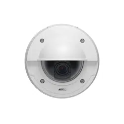
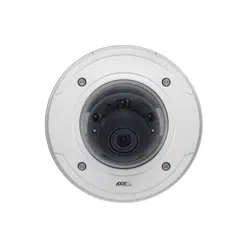
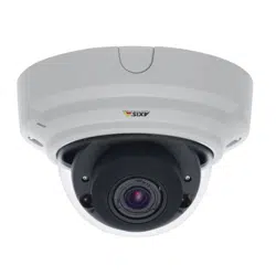
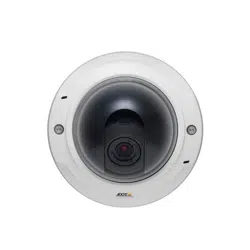
Hardware Overview
Hardware Overview
2
1
3 4 5 6 7
8 9
11
10
12
13
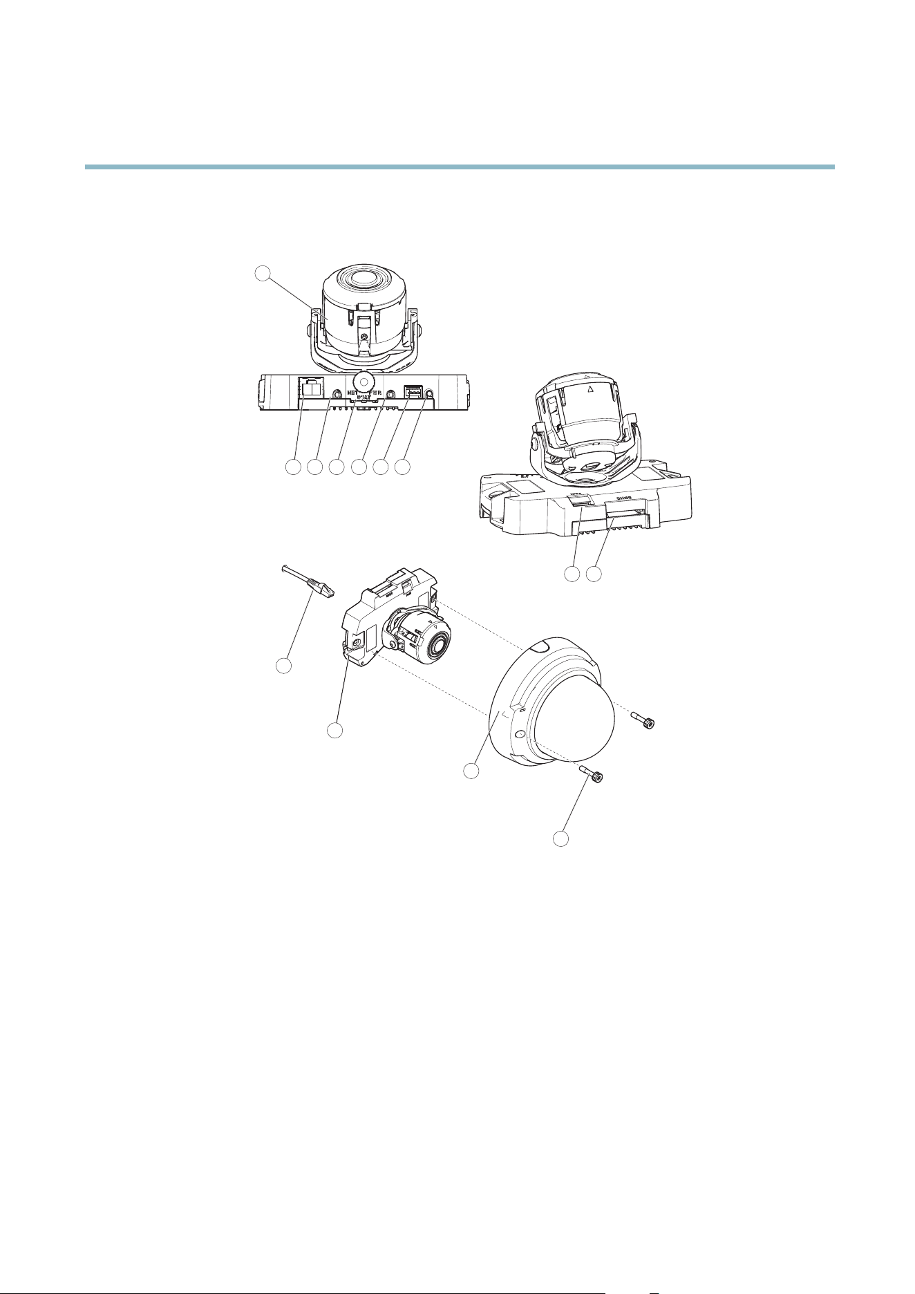
1.
Camera unit
2.
Network connector (PoE)
3.
Audio out
4.
LED indica tors
5.
Audio in
6.
I/O connector
7.
Control button
8.
Fan output connector
9.
SD memory card slot
10.
Network cable
11.
Camera unit
12.
Dome cover
13.
Tamper-proof screws
Connectors
For technical specifications, see
page 56
.
4

AXIS P3364–V
Hardware Overview
Network connector - RJ-45 Ethernet connector. Supports P ower over Ethernet (PoE).
NOTICE
Due to local reg ulations or the environmental a nd electrical conditions in which the product is to be used, a shielded
network cable (STP) may be appropriate or required. Any network cables that are routed in outdoor environments or similar
shall be shielded (STP) and intended for their specific use. Make sure that the network switch is properly grounded. See
Electromagnetic Co m patibility (EMC)
for regulatory requirements.
Audio in (pink) - 3.5 mm input for a m ono microphone, or a line-in m ono signal (left channel is used from a stereo signal).
Audio out (green) - 3.5 mm output for audio (line level) that can be connected to a pub lic address (PA) system o r an active speaker
with a built-in a m p lifier. A stereo connector must be used for audio out.
SD card slot - A standard or high-capacity SD card (not included) can be used for local recording with removable storage.
NOTICE
To prevent corruption of recordings, the SD card should be unmounted before removal. To unmount, go to Setup > System
Options > Storage > SD Card and click Unmount.
Control button - The control button is used for:
• ConnectingtoanAXISVideoHostingSystemservice.See
page 42
. To connect, press and hold the button for about
1 second until the Status LED flashes green.
• ConnectingtoAXISInternetDynamicDNSService. See
page 43
. To connect, press and hold the button for
about 3 seconds.
• Resetting the p rod uct to factory default settings. See
page 49
.
I/O terminal connector - Use in applications for e.g . motion dete c tion, event triggering, time lapse recording and alarm notifications.
In addition to an auxili ary pow e r and a GND pin, the I/O terminal connector pro vides the interface to:
• Digital output — For connecting external devices such as relays and LEDs. Connecte
d devices can be activated by
the VAPIX® Application Programming Interface, output b uttons on the Live View page or by an Action Rule. The
output will show as active (shown under System Options > Ports & Devices) if the alarm device is activated.
• Digital input — An alarm input for conne cting devices that can toggle between an open and closed circuit, for
example: PIRs, door/w indow contacts, glass break
detectors, etc. When a signal is received the state changes and
the input becomes active (shown under System Options > Ports & Devices).
LED Indicators
LED
Color
Indication
Green
Steady for connection t
o a 100 MBit/s network. Flashes for network activity.
Amber
Steady for connection to a 10 MBit/s network. Flashes for network activity.
Network
Unlit No network connection.
Green Steady g reen for normal operation.
Amber
Steady during startup and when restoring settings.
Status
Red
Slow flash for failed upgrade.
Green
Normal operation.
Power
Amber
Flashes green/amber during firmware upgrade.
5

AXIS P3364–V
Hardware Overview
Note
• The Status LED can be configured to be unlit during normal op eration. To configure, go to Setup > System Options >Ports
& Devices >LED. See the online help for more information.
• The Status LED can be configured to flash while an e vent is active.
• The S tatus LED can be configured to flash for identifying the unit. This can be done under Setup > System Options >
Maintenance.
6
AXIS P3364–V
Accessing the Product
Accessing the Product
To install the Axis product, refer to the Ins talla tion Guide supplied with the pro duct.
The product can be used with most operating systems and browsers. The recommended browsers are Interne t Explorer with Windows,
Safari w ith Macintosh and Firefox with other operating systems. See
Technical Specifications, on page 56
.Toviewstreamingvideoin
Internet Exp lore r, allow installation of AXIS Media C ontrol (AMC) w he n prompted.
Note
• Q uickTime
TM
is also supported for viewing H.264 streams and for audio.
• If your com puter restricts the use of additional software components, the product can b e configured to use a Java
applet for view ing Motion JPEG.
Access from a Browser
1. Start a browser (Internet Explorer, Firefox, Safari).
2. Enter the IP address or host name of the Axis product in the browser’s Location/Address field. To access the product from a
Macintosh computer (Mac OS X), click on the Bonjo ur tab and select the product from the drop-down list.
If you do not know the IP address, use A XIS IP Utility to locate the product on the netwo rk. For more information on how to
discover and assign an IP address, refer to the Installation Guide.
3. Enter your user name and password. If this is the first tim e the p roduct is acce ss ed , the root password must first be
configured; for instructions see
Set the Root Password, on page 8
.
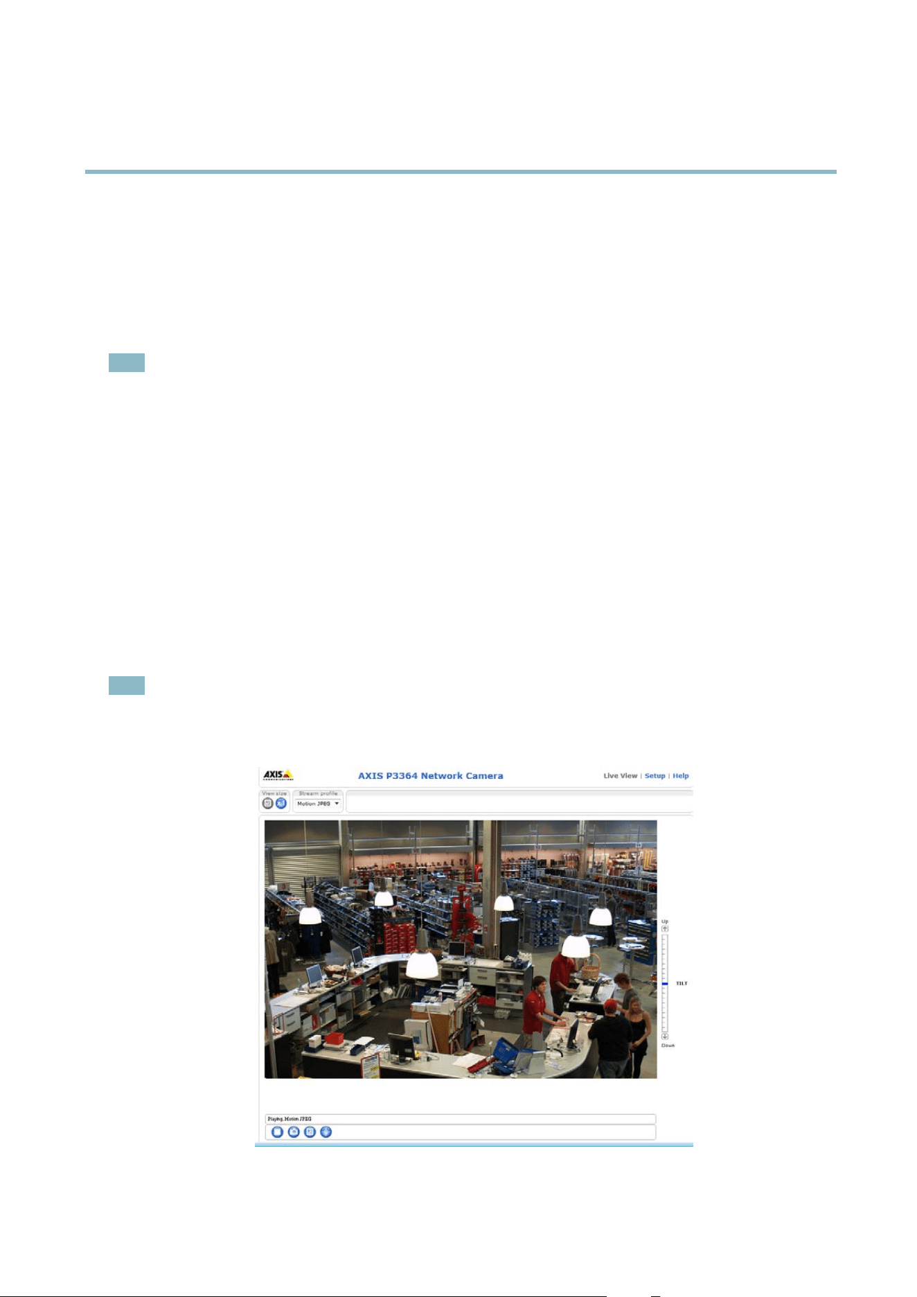
4. The product’s Live View page appears in your browser.
Note
The controls and layout of the Live View page m ay have been customized to meet specifi c installation requirements and
user preferences. Consequently, some of the examples and functions featured here ma y differ from those displayed in
your own Live View page.
7
AXIS P3364–V
Accessing the Product
Access from the Internet
Once connected, the Axis product is accessible on your local network (LAN). To access the p roduct from the Internet you must
configure your network router to allow incoming data traffic to the product. To do this, enable the NAT-traversal fea ture , which
will attempt to automatically con fi gure the router to allow access to the prod uct. This is enabled from Setup > System O ptions >
Network > TCP/IP Advanced.
For more information, please see
NAT traversal (port mapping) for IPv4, on page 44
. See also AXIS Internet Dynamic DNS Service at
www.axiscam.net For Technical notes on this and other topics, visit the Axis Support web at www.axis.com/techsup
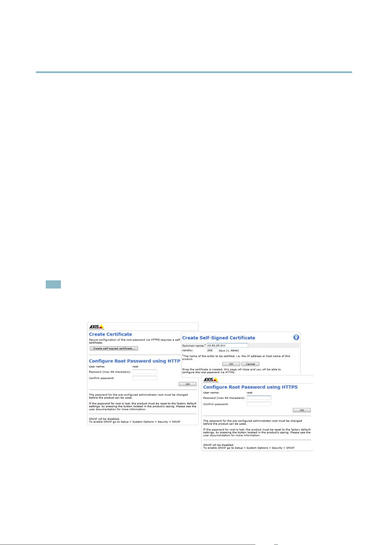
Set the Root Password
To gain access to the Axis product, you must set t he password for the default administrator user root. This is done in the Configure
Root Password dialog, which appears when the product is accessed for the first time.
To prevent network eavesdropping, the root password can b e set via an encrypted HTTPS connection, which requires an HTTPS
certificate. HTTPS (Hypertext Transfer Protocol over SSL) is a protocol used to encrypt traffic between web browsers and servers. The
HTTPS certificate ensures encrypted exchange of information.
To set the password via a standard HTTP connection, enter it directly in the first dialo g.
To set the password via an encrypted HTTPS connection, follow these steps:
1. Click Create self-signed certificate.
2. Provide the requested information and click OK.Thecertificate is crea ted a nd the password can now be set securely. All
traffic to and from the produ ct is encrypted from this point on.
3. Enter a password and then re-enter to confirm the spelling. Click OK. The password has now been configured.
Note
• The default administrator user name root is permanent and cannot be deleted.
• If the password for root is lost, the product must be reset to the factory default settings. See
Reset to Factory Default
Settings, on page 49
.
Set Power Line F requency
Power line frequency is set the first time the Axis product is accessed and can only be changed from Plain Config(see
page 49
)
or by resetting the product to factory default.
8
AXIS P3364–V
Accessing the Product
Select the pow er line frequency (50 Hz or 60 Hz) used at the location of the Axis product. Selecting the wrong frequency may cause
image flickeriftheproductisusedinfluorescent light environments.
When using 50 Hz, the max im um frame rate is limited to 25 fps.
Note
Power line frequency is different in different geographic regions. In the Americas, 60 Hz is usually used; most other parts of
the world use 5 0 Hz. Local variatio n s m ay apply, always check with the local authorities.
TheLiveViewPage
The controls and layout of the Live View page may have been customized to meet specific installation requirements and user
preferences. Consequently, some of the examples and functions featured here may differ from those displayed in your own Live View
page. T he following provides an overview of each available c ontrol.
Controls on the Live View Pa ge
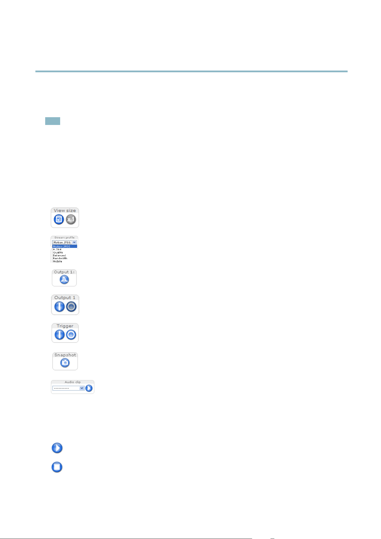
Click View size to scale the image down to 800 pixels wide or to full scale. Only available in MJPEG.
The Stream Profile drop-down list allows you to select a customized or pre-prog rammed stream profile. Stream
profiles are configured under Video & Audio > Stream Profiles.See
Stream Profiles, on page 17
.
Click Pulse to activate the output for a define d period of time, such as switching on an external light for 20 seconds.
Click the Active/Inactive buttons to manually start and stop a connected device — e.g. switch an external light
on and off.
The Manual Trigger b u tton can trigger an event directly from the Live View page. The bu
tton is configured under
Live View C onfig > Action Buttons.
Click Snapshot to save a snapshot of the video image. Right-click the video im age to save it in JPEG form at on your
computer. This button is primarily intended for use when the AX IS Media Control view er toolbar is not available.
Enable this button from Live View Config>ActionB
uttons.
The Audio clip drop-down list allow
s you to play an audio clip from the Live View page. Select the audio
clip and click the Play button.
AXIS Media Control view er toolbar
The AXIS Media Control viewer toolbar is ava ilable in Internet Explorer only. See
AXIS Media Control (AMC), on page 12
for more
information. The tool
bar displays the following buttons:
The Play button connects to the Axis product and starts playing a media stream.
The Stop button stops the m edia stream.
9
AXIS P3364–V
Accessing the Product
The Snapshot button takes a snapshot of the video image. The locationwheretheimageissavedcanbespecified
in the AMC Control Panel.
Click the View Full Screen button and the v ideo image will fill the entire screen. Press ESC (Escape) on the computer
keyboard to cancel full screen view.
The Record button is u sed to recor d the current video stream . The loca tion w h er e the reco rding is saved can be spe cified
in the AMC Control Panel.
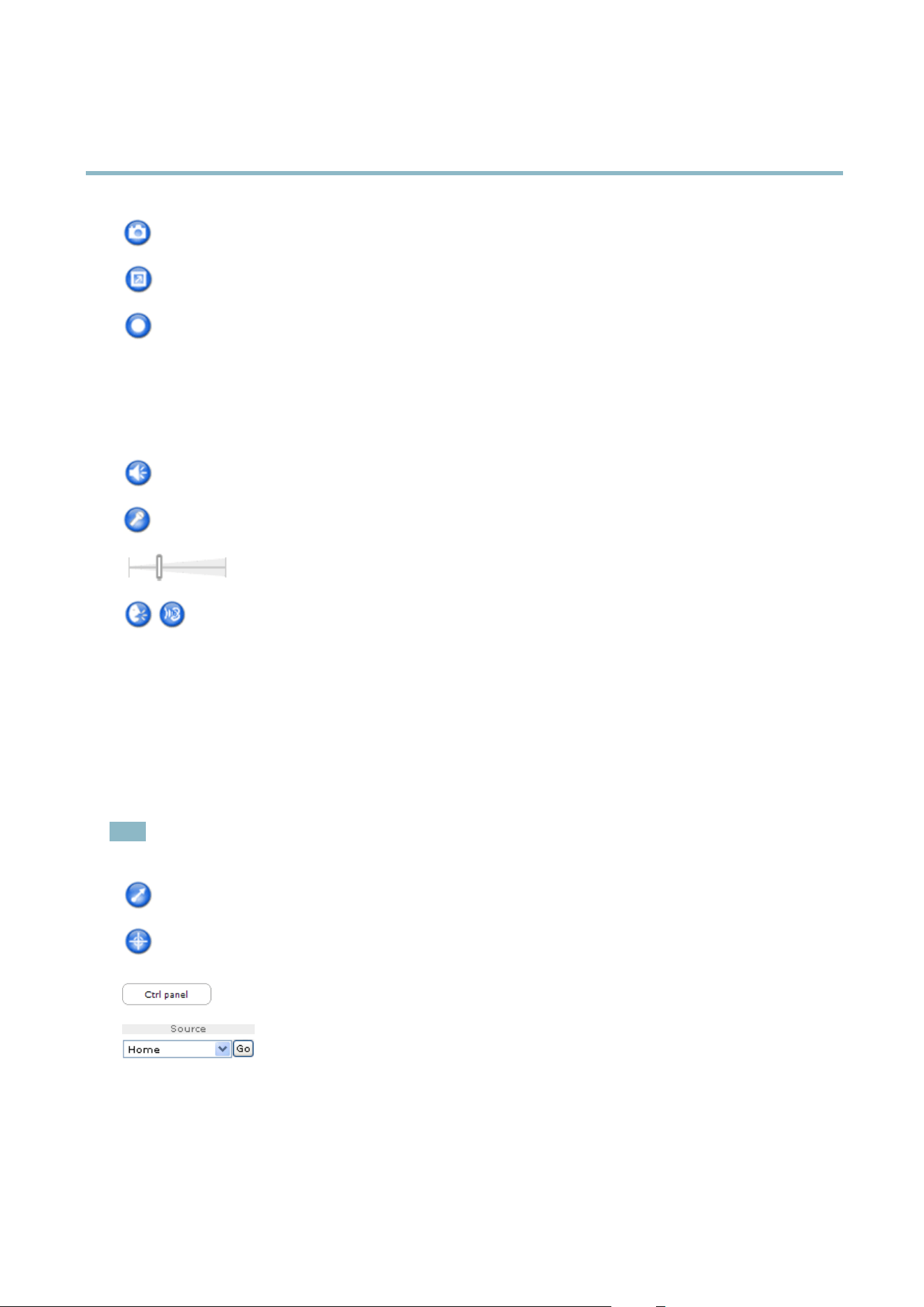
AMC Audio Controls
AMC audio buttons control the speakers and microphone connected to the client computer. The buttons are only visible when
audio is enabled.
Speaker button — C lick to turn the speakers on or off.
Microphone button – Click to m ute or unmute the microphone. In S implex - Network Camera speaker only mode,
click this button to stop sending audio to the product.
Use the slider to control the volume of the speakers and the microphone.
Half-duplex mode
The Talk/Listen button is used to switch between sending and receiving audio. The button can be configured
from the Audio tab in the AMC Control panel:
• Push-To-Talk mode: Click and hold the button t o talk/send. Release the button to listen.
• Toggle mode: Click once to switch betwe en talking and liste ning.
Simplex – Network Camera speaker only mode
To send audio, the Talk and Microphone buttons must both be enabled. Click either button to s top audio
transmission.
PTZ Controls
The Live View page also displays Pan/Tilt/Zoom (PTZ) controls. The administrator can enable/disable controls for specified users under
System Options > Security > Users.
Note
These controls are available if dig ital PTZ is enable d in the s e lecte d vie w are a, see
View Area, o n page 19
.
Click the Emulate joystick mode button and click in the ima ge to mo ve the camera view in the directio n of the
mouse pointer.
Click the Center mode button and click in the image to center the camera view on that positio n. The center mode
button could also be used to zoom in on a specific are a. Click in the image and drag to draw a rectangle surrounding
theareatobemagnified. To zoom out, rotate the mouse wheel.
Click the Ctrl panel button to open the PTZ control panel which pro vides additional PTZ controls.
User-defined buttons can also a ppear in the Control panel. See
Controls, on page 27
.
Select a PTZ preset position to steer the came ra view to the s aved position. See
Preset Positions,
on page 26
.
10

AXIS P3364–V
Accessing the Product
Pan and Tilt bars – Use the arrows to pan and t ilt the camera view , or click on a position on the bar to stee r the
camera view to that position.
Zoom bar – Use the arro ws to zoom in and out, or click on a position on the bar to zoom to that position.
The PTZ controls can be disabled under PTZ > Advanced > Controls,see
Controls, on pa g e 27
.
11

AXIS P3364–V
Media Streams
Media Streams
The Axis product provides several audio and video stream formats. Your requirem ents and the properties of your network will
determine the type you use.
The Live View page in the product provides access to H .264 and Motion JPEG video streams, audio streamsandtothelistofavailable
stream profiles. Other applications and clients can access video and audio streams directly, without going via the Live View page.
How to Stream H.264
The video compression standard H.264 makes good use of bandwidth, and can provide high quality video streams at less than 1 Mbit/s.
Deciding which combination of protocols and methods to use depends on your viewing requirements, and on the properties of
your network. The available options in AXIS Media Control are:
Unicast RTP
This unicast method (RTP over UDP) is used
for live unicast video, especially when it is
important to always have an up-to-date video
stream, even if some images are dropped.
RTP over RTSP
This unicast method (RTP tunneled over RTSP)
is useful as it is relatively simp le to con figure
firewallstoallowRTSPtraffic.
RTP over RTSP over HTTP
This unicast method can be used to traverse
firewalls. Firewalls are commonly configured to
allow the HTTP protocol, thus allowing RTP to
be tunneled.
Unicasting is used for video-on-demand
transmission so that there is no video traffic
on the network until a client connects and
requests the stream.
Note that there are a maximum of 20
simultaneous unicast connections.
Multicast RTP
This method (RTP over UDP) should be used for liv e m ulticast video. The video stream is always
up-to-date, even if some images are dropped.
Multicasting provides the m ost efficient usage of bandwidth w hen there are large numbers of
clients viewing simultaneously. A multicast cannot however, pass a network router unless the
router is configured to allow this. It is not possible to multicast over the Internet, for example.
Note a lso that all multicast view ers count as one unicast view er in the maximum total of 20
simultaneous connections.
AXIS Media Control negotiates with the Axis product to determine the transport protocol to use. The order of priority, listed in the
AMC Control Panel, can be chang ed and the options disabled, to suit specific requirements.
Note
H.264 is licensed technology. The Axis product includes one H.264 viewing client license. Installing add itional unlicensed
copies of the client is prohibited. To
purchase additional licen se s, contact you r Axis reseller.
MJPEG
This format uses st anda rd JPEG still images f or the video stream. These images are then displayedandupdatedataratesufficient
to create a s tream that shows co nstantly updated mo tion.
The Motion JPEG stream uses considerable amounts o f bandw idth, but provides excellent image qualityandaccesstoeveryimage
contained in the stream. The recommended method of accessing Motion JPEG live video from the Axis product is to use the AXIS
Media C ontrol in Internet Explorer in Window s.
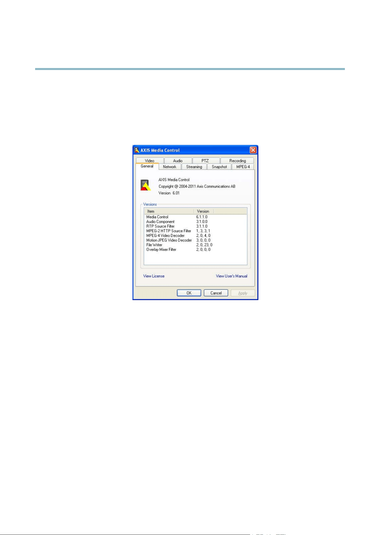
AXIS Media Control (AMC)
AXIS Media Control (AMC) in Internet Explorer in Windows is the recom m e nded method of accessing live video from the Axis product.
12
AXIS P3364–V
Media Streams
TheAMCControlPanelcanbeusedtoconfigure various video and audio settings. Please see the AXIS Media Control User’s
Manual for more information.
The AMC Control Panel is autom atically installed on first use, after which it can be configured. Open the AMC Control Panel from:
• Windows Control Panel (from the S tart menu)
• Alternatively, right-click the video image in Internet Explorer and click Settings.
Alternative Methods of Accessing t he Video Stream
You can also access video and images from the Axis product in the follow ing ways:
• Motion JPEG server push (if supported by the client, Firefox, for example). This option maintains an open HTTP connection
to the brow s er and sends data as an d when required , for as long as required .
• Still JPEG images in a browser.Enterthepathhttp://<ip>/axis-cgi/jpg/image.cgi
• Windows Media Player. This requires AXIS Media Control and the H.264 decoder to be installed. The following paths
can be used:
- Unicast via RTP : axrtpu://<ip>/axis-media/media.amp
- Unicast via RTSP: axrtsp://<ip>/axis-media/media.amp
- Unicast via RTSP, tunneled via HTTP: axrtsphttp://<ip>/axis-media/media.amp
-Multicast:axrtpm://<ip>/axis-media/media.amp
• QuickTime
TM
. The following paths can be used:
- rtsp://<ip>/axis-media/media.amp
- rtsp://<ip>/axis-media/media.3gp
13

AXIS P3364–V
Media Streams
Note
• <ip>= IP addess
• The Axis product supports QuickTime 6.5.1 and later.
• Q uickTime adds latency to the video stream.
• It may be possible to use other players to view the H.264 stream using the paths above, although Axis does not guarantee
this.
Accessing Audio Streams
The Live View pag e provides access to audio through AXIS Media Control; in addition audio can be accessed in the following ways:
• VAPIX® Application Programming Interface (API) For more information, visit www.axis.com/developer
• Windows Media Player supports simplex audio. The following paths can be used:
- Unicast via RTP : axrtpu://<ip>/axis-media/media.amp
- Unicast via RTSP: axrtsp://<ip>/axis-media/media.amp
- Unicast via RTSP, tunneled via HTTP: axrtsphttp://<ip>/axis-media/media.amp
-Multicast:axrtpm://<ip>/axis-media/media.amp
• QuickTime
TM
supports G.711 and AAC audio encod ing. The following paths can be used:
- rtsp://<ip>/axis-media/media.amp
- rtsp://<ip>/axis-media/media.3gp
•TheJava applet supports simplex audio with G.711 encoding.
14

AXIS P3364–V
Setting Up the Product
Setting Up the Product
The Axis product can be configured by users w ith administrator or operator rights. Click Setup in the top right-hand corner of
theLiveViewpage.
• Administrators have unrestricted access to all settings.
• Operators have access to all settings except System Options
See also the online help .
Basic Setup
Basic Setup provides shortcuts to the settings thatshouldbemadebeforeusingtheAxisproduct:
1. Users. See
page 38
.
2. TCP/IP. See
page 42
.
3. Date & Time. See
page 41
.
4. Video Stream. See
page 16
.
5. Focus & Zoom. See
page 21
.
6. Audio Settings. See
page 22
.
The Basic Setup menu can be disabled from System Options > Security > Users.
15
AXIS P3364–V
Video and Audio
Video and Audio
The video and audio settings can be used to optimize video an d audio quality. You can configure the following:
• Video stream settings. See
page 16
.
•Streamprofiles. See
page 17
.
• Camera settings. See
page 17
.
•Viewarea.See
page 19
.
• Overlay image. See
page 20
.
•Privacymask.See
page 21
.
• Focus and zoom. See
page 21
.
• Audio settings. See
page 22
.
• Audio clips. See
page 23
.
Video Stream
You can defi ne the following video stream settings from Video & Audio > Video Stream:
•Image.See
page 16
.
• H.264. See
page 17
.
•MJPEG.See
page 17
.
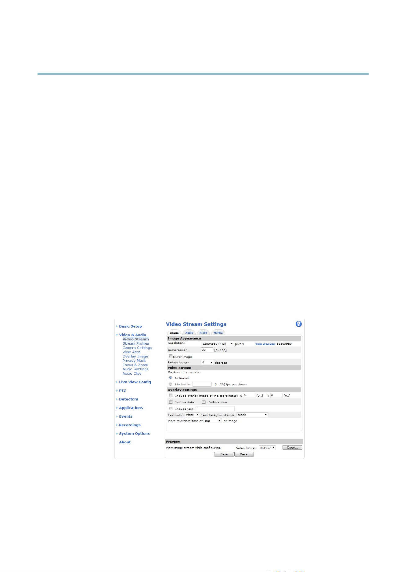
Image
You c an modify the image resolution and compression, and rotate the image from the Image tab (Video & Audio > Video Stream).
The im ag e can also be m irr o re d from the Image tab.
16

AXIS P3364–V
Video and Audio
Setting the compression level affects the image quality and bandwidth; the low er the compression, the higher the image quality
with higher bandwidth requirements.
To avoid bandwidth problems on the network, you can limit the frame rate allowed to each viewer. The maximum frame rate can be
set to Unlimited, or you can lim it the frame rate to a value.
An image or text can be superimposed over the image as overlay. See
Overlay, on page 20
.
Save your settings before they can take effect.
H.264
H.264, also known as MPEG-4 Part 10/AVC, is a video compression standard that provides high q uality video streams at low bit rates.
An H.264 video stream consists of different types of frames such as I-frames and P-frames. An I-frame is a com ple t e image where as
P-frames only contain the differences from pr evious frames.
The GOV length is the number o f frames between two consecutive I-frames. Increasing the GOV length may save considerably on
bandwidth requirements in some cases, but may also have an adve rse affect on image quality.
The Axis pro duct supports two H.264 profiles.TheMainprofile provides higher compression than the Baseline pro file with the same
video quality, but requires more processing power to decode.
ThebitratecanbesetasVa riable Bit Rate (VBR) or Constant Bit Rate (CBR). VB R adjusts the bit rate according to the image
complexity, using up more bandwidth for increased activity in the image, and less for lower image activity. CBR allows you to set a
fixed Target bit rate that consumes a predictable amount of bandwidth. As the bit rate wo uld usually need to incre as e for increased
image activity, but in this case cannot, frame rate and image qualityareaffectednegatively. Topartly compensate for this, it is
possible to prioritize either fra m e rate or im age quality. Not setting a priority means that fram e r ate and image quality are equally
affected. Yo u must save your settings before they c an take effect .
The current bit rate can be set to appear as text overlay. To do this, select the Include text check box option under Overlay
Settings and enter the modifier#b in the field.
MJPEG
Sometimes the image size is large due to low light or complex scene ry. Adjusting the ma xim um frame size helps to control the
bandwidth and storage used by the Motio n JPE G video stream in these situations. Setting the frame size to the Default setting
provides consistently good image quality at the expense of increased ba
ndwidth and storage usage in low light. Limiting the fr ame
size optimizes bandwidth and storage usage, but may give poor image quality. To prevent increased bandwidth and storage usage,
the ma ximum fram e size should be set to an optimal value.
Stream Profiles
Astreamprofile is a set of pr e-con figured stream settings i ncluding resolution, compression, frame rate and overlay settings.
Stream profiles can b e use d :
• When setting up recording using action rules, see
Events, on page 32
.
• When setting up a c ontinuous recording, see
Continuous Recording, on page 36
.
• In the Live View page — select the stream profile from the Stream profile drop-dow n list.
Four pre-programmed stream profi l es are availab le for quick set up. Each pre-progr am m e d profile has a des criptive nam e, indicating
its purpose. If required, the pre-programmed s tream profiles can be modified and new customized stream profiles can be created.
To create a new profile or modify an existing pro file, go to Setup > Video & Audio > Stream Profiles.
To select a default stre am profile for the Live View page, go to Setup > Live View Config.
Camera Settings
The Video & Audio > Camera Settings page provides access to advanced image settings for the Axis product.
17

AXIS P3364–V
Video and Audio
Image Appeara nce
Increasing the Color level increases the color saturation. The value 100 gives maximum c olor saturation. The value 0 gives a
black and white image.
The image Brightness can be adjusted in the range 0–100, where a higher value prod uces a brighter image.
Increasing the Sharpness can increase bandwidth usage. A sharper im age m ight increase image noise especially in low light
conditions. A lower setting reduces image noise, but the whole image will appear less sharp.
The Contrast changes the re lati ve difference between lig ht and dark. It can be adjusted using the slidebar.
White Balance
White balance is used to m ake colors in the image appear the same regardless of the color tem per ature of the light source. The Ax is
product can be set to automatically identify the light source and compensate for its color. A lternatively, select the type of light
source from the drop -dow n list. For a de scription of each available setting, see the online help
.
The white balance window is enabled for the Automatic and Autom atic outdoor options that appear in the White balance drop-down
list. Select one of the options fro m the drop-down list to set the white balance w indo w properties. Select Automatic to use the
default settings for the Automatic and Autom atic outdoor options (in the W hite balance drop-down list). Select Custom to manually
set a reference window for white balance in the view area.
Wide Dynamic Range
Wide dynamic range (Dynamic Contrast) can impro ve the exposure when there is a considerable contrast between light and dark
areas in the image. En ab le WD R in intense backlight conditions. Disable WDR in low light conditions f o r optimal exposure .
Note
This setting is only possible when usi ng automatic exposure control.
Exposure Settings
Configure the exposure settings to suit the image quality requirements in relation to l
ighting, frame rate and bandwidth
considerations.
Exposure value - Click in the bar to fine-tune the expo sure.
Exposure control - These settings is used to adapt to the amount of light used. Automatic is the default settings can be used in most
situations. The shutter speed is automati cally set to produce optimum image quality. Flicker-free 50 or 60 Hz is used to remove
flicker which can b e caused by fluorescent a nd oth
er light sources. The Hold current option locks the current exposure settings.
Enable B acklight com p ensation - Ena b le t
his option if a bright spo t of light, for example a light bulb, causes other areas in
the image to appear too dark.
Exposure zones - This settings determines which part of the image is used to calculate the exposure. For m ost situations, the Auto
setting can be used. For particular requirement, select a predefi ned area.
Shutter & Gain
The shutter and gain settings affect the amount of motion blur and noise in the image. To ad apt to different lighting, available
storage space and bandwidth, it is often necessary to prioritize either low motion blur or low noise. The Axis product allows
using differ
ent pri oritiza tion in normal light and in l ow light.
Shutter
speed is related to the amount of time the shutter is opened and is measured in seconds (s). A slow shutter speed allows
more light to reach the sensor and can help produce a brighter image in low light situations. On the other hand, a slow shutter
speedcancausemovingobjects to appear blurry.
Set Shutter to
• Auto to set the shutter speed automatically. If required, use Max shutter to limit the shutter speed to prevent the frame
rate from being reduced. For example, to get 30 fps, set Max shutter to 1/30.
18

AXIS P3364–V
Video and Audio
• Fixed to use a fixed shutter speed.
Gain, measured in decibel (dB), is the amount of amplification applied to the image . A high ga in ma y provide a better im ag e in low
light situations but will incre ase the amount of image noise.
Set Gain to
• Auto to set the gain automatically. If required, use Max gain to limit the applied gain.
• Fixed to use a fixed g ain.
When Shutter and Ga in are both set to Auto, i t is possible to set the Priority between low motion blur and low noise manually and to
use a different Priority in Normal Light and in Low Light.
Example
Consider an area where people or vehicles move during the day, but where there should be no movements during night. To be able to,
for example, recognize faces or license plates, move the normal light priority slider toward low motion blur. At nighttime, m o t ion
detection is more important than identifi cation. Mo tion blur is acceptable and since low light can cause a lot of noise, mo ve
the low light priority slider toward low noise.
Example
If s tora ge space or bandwidth is limited, try using a lower gain. This will reduce im age noise and produce smaller image files.
Iris adjustment
Select Enable automatic iris a djustment to a utom atica lly compensate for changing light conditions. This option is n ot available
if a fixed iris is used.
Use the Iris adjustm ent slider to set the preferred F-value. The scale represents the amount the iris is open. If set to 0, the iris
is opened as much as possible. If set to 100, the iris is closed as much as possible. The actual F-value is shown below the
slider. If autom atic iris adjustment is enabled, the iris will stay at this position as long as light conditions are favorable. If light
conditions change, the iris will adjust itself to the best iris settings. If automatic
iris adjustment is disabled, the iris will lock on
the s et position regardless of light conditions
Day/Night
The IR cut filter prevents infrared (IR) light from reaching the image sen
sor. In poor lighting conditions, for example at night, o r
when using an IR lamp, set the IR cut filter to Off. This increases light sensitivity and allows the product to “see” infrared light. The
image is shown in black and white w hen the IR cut filter is off.
If using automatic Exposure control,settheIRcutfilter to Auto to automatically sw itch between On and Off accordingtothe
lighting conditions.
The Day/Night shift level bar helps d
etermine w h e n the camer a will shift from day mode to night mode. Normally, the camera
automatically changes mode from day to night when
very dark (level 100 in the slider). By setting Day/Night shift level to a
lower value, the camera will change to night mod e earlier.
View Area
A vie w area is a cropped part of the full view. The view area is treate d as a video source in Live View and has its o wn video
stream and PT
Zsettings.
When se
tting up a view area it is recom m e nde d tha t the video stream resolutio n is the same size as or smaller tha n the vie w a re a
size. Setting the video stream resolution larger than the view ar ea size implies digitally sc ale d up video after sensor capture,
requiring more bandwidth without a dding image information.
To enable a view are a, go to Video & Audio > Camera Settings and select Enable View Area.
To configure the view area:
1. Go to Video & Audio > View Area.
19

AXIS P3364–V
Video and Audio
2. Select an Aspect ratio and a Video stream resolution.
3. Use the mouse to move and resize the view area.
4. Select Enable PTZ to enable digital PTZ for the view area.
5. Click Save to save the settings.
Tip:
• The PTZ functionality is useful during installation of the Axis product. U se a view area to crop out a specificpartof
the full view.
Overlay
Overlays are used to provide extra information, for example for forensic video analysis or during product installa tion an d
configuration. Overlays are s u pe rimposed over the video stream.
An overlay text can display the current date a nd ti me, or a text string. When using a text string, modifiers can be us ed to display
information s uch a s the current bit ra te or the current frame rate. For information about a vailable modifiers, see
File Naming &
Date/Time Formats
in the o nline help .
To enable over lays:
1. Go to Video & Audio > Video Stream and select the Image tab.
2. To include an overlay image, select Include overlay image at the coordinates. The overlay image must first be uploaded to
the A xis product, see
Overlay Image
.
3. To include date and time, select Include date and Include time.
4. To include a text string, select Include text and enter the text in the field. Modifier s can be used, see
File Nam ing &
Date/Time Formats
in the online help .
5. Select the text color, the text background color and the position of the o verlay.
6. Click Save.
Tomodifythedateandtimeformat,gotoSystem Options > Date & Time.See
Date & Time, on page 41
.
Overlay Image
An overlay image is a static
image superimposed over the video stream. The image, for example com pany log o, is used to provide
extra information or to mask a part of the image.
To use an overlay image, the image must first be up loaded to the Axis product:
1. Go to Video & Audio > Overlay Image.
2. Click Brow se andbrowsetothefile.
3. Click Upload.
4. Select the image to use from the Use overlay image lis t.
5. Click Save.
To display the overlay image:
1. Go to Video & Audio > Video Stream and select the Image tab.
2. Under Overlay Settings,selectInclude overlay image at the coordinates and enter the X and Y coordinates.
20

AXIS P3364–V
Video and Audio
3. Click Save.
For information about supported image formats, see the online help
.
Privacy Mask
A privacy mask is an area of solid colo r that prohibits users from v iewing parts of the monitored a rea. Privacy masks cannot be
bypassed via the VAPIX® Application Programming Inte rfa ce (API).
The Privacy M ask List (Video & Audio > Privacy Mask) shows all the masks that are currently configured in the Axis product and
indicates if they are enabled.
You can add a new mask, re-size the mask with the mouse, choose a color for the mask, and give the mask a name.
For m ore information, see the online help
Important
Adding many p rivacy masks may affect the product’s perform ance.
Focus & Zoom
Focus and zoom should only be configured when installing or reinstalling the product. For installation instructions, refer to the
product’s Installation Guide.
To set focus and zoom:
1. Install the camera as d escribed in the Insta lla ti on Guid e.
2. Go to Video & Audio > Focus & Zoom.
3. On the Basic tab, set the zoom level using the slider. The buttons < and > move the zoom position one step in either
direction. The buttons << and > > m o ve the zoom position in multiple steps in either direction.
4. Click Perform auto focus to focus the cam era automatically.
5. If more adjustments are needed, go to the Advanced tab.
Note
• C hanging the zoom level moves the fo cus position. Focus should always be adjusted after changing the zoom.
• Movements in front of the camera should be avoided during automatic focusing.
The Pixel counter shows the number of pixels in an area of the image and can be used to ensure that the size of the image
fulfills cer tai
n requirements, for example for face recognition. Use the m ouse to move and resize the pixel counter, or enter the
number of pixels in the Width and Height fields and click Apply.
On the Advanced tab, focus can be adjusted manually:
1. Click Open iris to ope n the iris to its maxim um position. This give s the smallest depth of field and provides the b est
conditions for focusing.
2. Focus is set in the Focus window. U se the mouse to move and resize the focus window.
3. Set the zoom level using the slider and click Perform auto focus to focus the camera automatically.
4. Click in the Focus position bar to focus on a desired location. The buttons < and > m ove the focus position one step in
either direction. The buttons << and >> move the focus position in multiple steps in either direction.
5. When satisfied, click Enable iris to enable the iris.
21

AXIS P3364–V
Video and Audio
Audio Settings
The audio functionality for each video stream is enabled under Video & Audio > Video Stream > Audio.
Audio Channels
Select the type of audio transmission from the Audio m ode: drop-down list (Video & Audio> Audio Settings). The diffe rent types are:
Full duplex - Simultaneous two-way audio allowing you to transmit and receive audio (talk and listen) at the same time. There is no
echo cancellation; if feedback loops appear, try moving the microphone or the speaker.
Half-duplex - Audio can be transmitted in both directions between the Axis product and the client computer, but only in one
direction at a time. You must actively receive sound using the Talk/Listen button visible in the Live View page (see
AXIS Media
Control viewer toolbar
). In Push-To-Talk mode , click and hold the button to speak and release it when done. In Toggle mode, click
once to switch between speaking and listening. The Talk/Listen mode is configured from the Audio tab in the AMC control panel
(see A XIS Media Control on
page 12
).
Simplex - Network Camera speaker only - Audio is transmitted from the client to the Axis product and played by the speaker
connected to the product. To send audio, the Talk and Microphone buttons in the AMC toolbar must bo th be enabled. Click either
button to stop audio transmission.
Simplex - Network Camera microphone only - Audio captured by the microphone connected to the Axis product is transmitted from
theproducttooneormoreclients.
For more information about these settings, please see the online help
.
Audio Input
An external microphone or a line source can be connected to the product’s Audio-in connector. Configure the audio input se ttings
under Video & Audio > Audio Settings.
Note
The internal microphone is used by default ; the external microp hone is used when conn
ected. It is possible to disable the
internal microphone by connecting a plug to the mic input.
Source - Select Microphone for an external microphone or Line for a Line in device, e.g. an audio mixer for multiple microphones or
a microphone with a built-in amplifier.
Microphone power - The Enable microphone power option provides DC power for a n external microphone. Microphone power should
only be used with microphones that have no battery and when using the internal microphone. This setting should not be enabled
when using a dynamic or ba ttery powered microphone. Microphone power will not harm the micro phone; if you are uncertain, try
switching it off and on. To use a professional m icrophone requiring 48V phantom power, you need an external power supply and a
balanced-unbalanced converter (audio tra n sfor m er) in be tween.
Input gain - Control the volume (dB Full Scale) of the audio input. If the sound is to o low, choose a higher dB, to amplify the
sound. If the sound is too high, choose a lower dB. The Level bar gives a visua l representation of the audio signal level in dB
relative to the full-sc
ale i nput level.
• Green — the signal is at a good level.
• Yellow — the signal is becoming distorted.
• Red — the signal is distorted.
Encoding - Select digital audio encoding format.
• AAC requires a license for both encoding and decoding. A AC is the least complicated a nd most widely used codec.
If achieving the best possible audio quality is a priority, AAC is the recommended codec to use. An AAC license
is included in the A xis pr oduct.
22

AXIS P3364–V
Video and Audio
• G711
• G726
Sample rate - The number of times per second the sound is sampled. A higher sample r ate will provide bette r a udio quality, but
also requires a greater bandwidth.
Bit rate - Set the required bit rate depending on the selected encoding. A higher bit rate will give better audio quality. A lower bit
rate may have latency or delay, but will require less b andwidth.
For more information about these settings, please see the online help
.
Audio O utput
An external speaker can be connected to the product’s Audio-out connector (a built-in amplifier is required for this). The output can
be connected to another amplifier with speakers. A stereo connector must be used for the audio out.
Configure the audio output settings under Video & Audio > Audio Settings.
Output gain - Control the volume (dB Full Scale) of the line audio output. If the sound is too low, choose a higher dB. If the
sound is too high, choose a lower dB.
Audio Clips
An audio clip is a sound file that can be played either when a n event occurs or manually from the Live View page. Audio clips can
be uploaded to the product or recorded by a microphone connected to the product.
You can add, play, download, modify and remove audio clips from Video & Audio > Audio Clips. For more information see the
online help
.
Note
Audio clips cannot be used if the prod uct’s audio functionality is enabled. The audio functionality is enabled on the Audio
tab under Video & Audio > V ideo Stream.
23
AXIS P3364–V
Live View Config
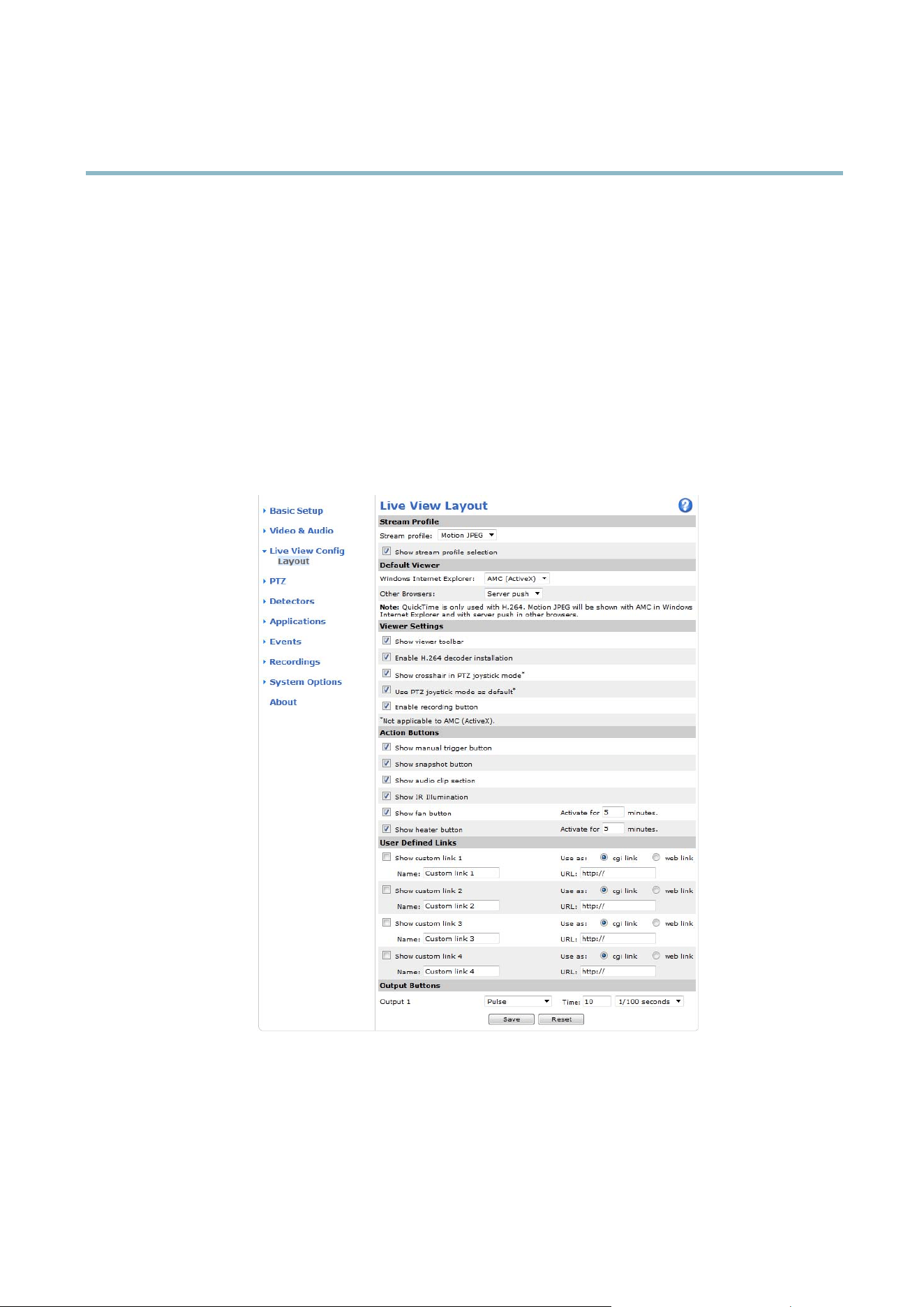
Live View Config
You can customize the Live View page and alter it to suit your requirements. It is possible to define the following features of
theLiveViewpage.
•StreamProfile. S ee
page 17
.
• Default Viewer for Browser. See
page 24
.
• Viewer Settings. See
page 25
.
• Action Buttons. These are the buttons described in
Controls on the Live View Page, on page 9
.
•UserDefined Links. See
page 25
.
• Output B uttons. See
page 25
.
Default Viewer for Browsers
From Live View Config > Default V iewer select the default method for viewing video images in your browser. The product attempts
to show
the video images in the selected v ideo format a n d viewer. If this is not possible, the product overrides the settings and
selects the best available combination.
24

AXIS P3364–V
Live View Config
Browser Viewer Description
AMC
Recommended viewer in Internet Explorer (H.264/Motion JPEG)
QuickTime
H.264
Java applet
A slower imaging a ltern ative to AMC (Motion JPEG). Require s one of the
following installed on the client:
• JVM (J2SE) 1.4.2 or higher
• JRE (J2SE) 5.0 or higher
Windows Internet Explorer
Still image Displays still images only. Click the Refresh button in your brow se r to view a
new image
Server Push
Recommended viewer for other browsers (Motion JPEG).
QuickTime
H.264
Java applet
A slower imaging alternative to Serve r Push (Motion JPEG only).
Other browsers
Still image Displays still images only. Click the Refresh button in your brow se r to view a
new image
For more inform a tion, ple ase see the online h elp .
Viewer Settings
Options for the viewer are configured under Live View Config > Viewer Settings.
•TheShow viewer toolbar option w ill display the AXIS M edia Control (AMC) or the QuickTime viewer toolbar under the
video image in your browser.
• H.264 decoder installation. The administrator can d isable installation of the H.264 decode r included with AXIS Media
Control. This is used to prevent installation of unlicensed copies. Further decoder licenses can be purchased from your
Axis reselle r.
•SelectShow crosshair in PTZ joystick mode to ena ble a cross that will indicate the center of the im age in PTZ joystick mode.
•SelectUse PTZ joystick mode as default to enable joystick mode. The mode can be changed temporarily from the PTZ
control panel.
• You can enable recording from the Live View page. The recordings are saved to the location specified in the AMC Control
Panel. See
AXIS Media Control (AMC), on p age 12
.
User Defined Links
To display user-defined links in the Live View page, select the Show custom link op tion, give the link a name and then enter the URL
to link to. W hen d efining a web link do not remove the 'http://' from the URL address. Custom links can be used to run scripts or
activate external devices connected to the product, or they can link to a web page. Custom links defined as cgi links will run the
script in the b ackground, in a hidden frame. Defining the link as a web link will open the link in a new wind ow.
Output Buttons
An output on the Axis product can be controlled directly from the Live View page, by enabling the display of output buttons. To
display the output buttons in the Live View page, select the type of control to use for the port from the drop-down list under
Live View Config > Output Buttons:
• Pulse activates the output for a definedperiodoftime. Thepulsetimecanbe set as short as 1/100 second, and as
long as 60 seconds
• Active/Inactive displays two buttons (on/off). The output ports must first be configured under System Options> Ports &
Devices > I/O Ports.See
I/O Ports, on page 47
.
25
AXIS P3364–V
PTZ (Pan Tilt Zoom)
PTZ (Pan Tilt Zoom)
The PTZ me nu is available if digital PTZ (pa n, tilt and zoom) is enabl ed in the selected view area. For more information on view areas,
see
View Area, on page 19
.
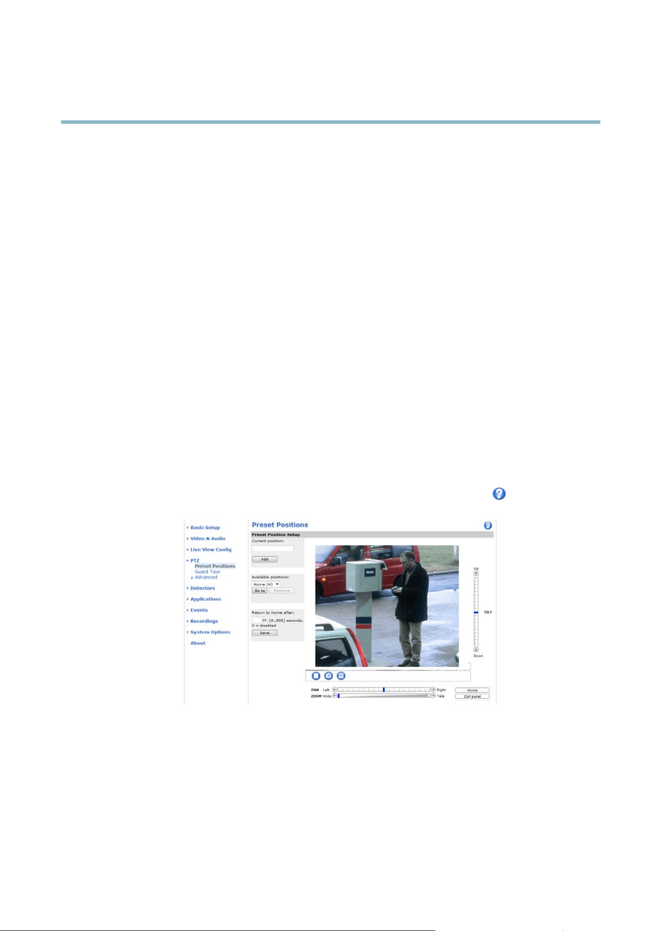
Preset Positions
A preset position is a predefined view that can be used to quickly steer the camera to a specific location. Preset positions can
be accessed in several ways:
• By selecting the preset from the Preset positions drop-down list in the Live View Page.
• When setting up action rules. See
page 32
.
• When setting up Guard Tour. See
page 26
.
To add a preset position:
1. Go to PTZ > Preset Positions.
2. Use the pan, tilt and zoom controls to steer the camera view to the desired position.
3. Enter a descriptive name in the Current position field.
The product can be configured to return to the Home position when the PTZ functionality has bee n inactive for a specified length
of time. Enter the length of time in the field a nd click Save. S et the time to zero to pre vent the product from automatica lly
returning to the Home position.
To include the preset position name in the overlay text, go to Video & Audio,selectInclude overlay text and enter the modifier #P in
the field. For more information about modifiers, see
File Nam i n g & Date /T
ime Formats
in the online help .
Guard Tour
A guard tour displays the video st re am from different preset positions, one-by-one, in a predetermined order or at random and for
c
onfigurable time periods. The enabled guard tour will keep running after the user has logged off or closed the browser.
Toaddaguardtour:
1. Go to PTZ>GuardTourand click Add.
2. Enter a descriptive name.
26

AXIS P3364–V
PTZ (Pan Tilt Zoom)
3. Specify the pause length between runs.
4. Select an available preset position and click Apply.
5. Specify the View Time in seconds or minutes.
6. Specify the View Order or select the Random view order option.
7. Click Save.
To mo dify or remove guard tours, go to PTZ>GuardTour, select the guard tour in the Guard T our List and click Modify/Remove.
For m ore information see the online help
.
Advanced
Limits
Define the pan, tilt, zoom and focus limits for the Axis p roduct. Movements to the left and right, up a nd down, can be restricted to
narrow the area under surveillance.
Move speed sets the speed of the camera’s pan and tilt movements. The default setting is maximum speed.
When using a joystick (or emulating one with the mouse) the Enable proportional speed setting can be used to reduce the maximum
pan/tilt m ove ment speed, i.e. the speed the camera view m oves at w h en the jo ystick is pus hed all the way out in any direction. This is
useful then the view is z oomed in on an object.
See the online help for more information.
Controls
Panel Shortcut Command Buttons can b e configured to provide direct access to commands issued via the VAPIX® Application
Programming Interface. The buttons will be displayed in the PTZ con
trol panel, which is available in the Live View page through
the Ctrl panel button, see
page 10
.
27

AXIS P3364–V
Detectors
Detectors
Camera Tampering
Camera Ta m per ing can generate an alarm w hene ve r the camera is repositioned, or when the lens is covered, sprayed or severely
defocused. To send an alarm, for example an email, an action rule must be set up.
To configure tampering:
1. Go to Detectors > Camera Tampering.
2. Set the Minim u m duration, that is, the time that m us t e laps e before an alarm is generated. This can h el p prevent false
alarms for known conditions that affect the image.
3. Select Alarm for dark images if an alarm should be generated if lights are dimmed or turned off, or if the lens is sprayed,
covered, or rendered severely out of focus.
4. Click Save.
To configure the product to send an alarm when tampering occurs:
1. Go to Events > Action Rules.
2. Click Add to set up a new action r ule.
3. Enter a Name for the action rule.
4. Under Condition,selectDetectors from the Trigger list.
5. Select Tamp erin g from the list of detectors.
6. Optionally, sele ct a schedule and set additional conditions.
7. Select the action. To send an email, select Send Notification a
nd select a Recipient from the list of defined recipients.
Note
The While the rule is active option under Duration cannot be used with camera tampering, since camera tampering does not
have a duration and once it has been triggered it will not automatically return to its untrigge re d state .
For more information on actions r ules, see
Events, on page 32
.
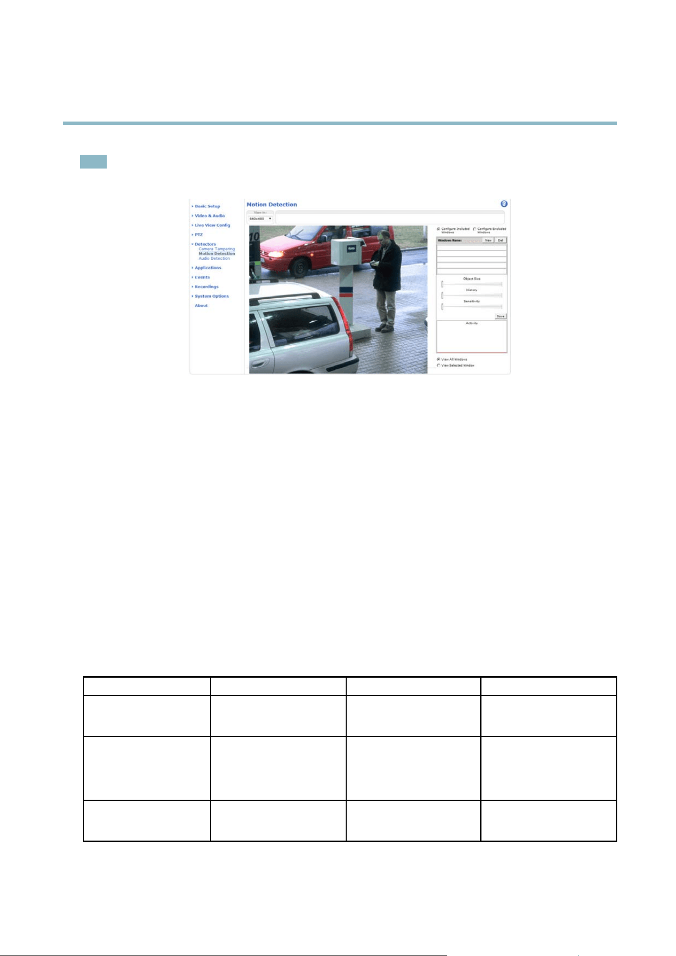
Motion Detection
Motion detection is used to generate an alarm w h enever movement starts or stops in the camera view.
Motion detection is configured by defining up to 10 Include and Exclude windows:
• Include windows —define areas where motion should be detected
• Exclude windows —define areas w ithin an Include window that should be ignored (areas outside Include windows
are automatically ignore d).
For instructions, see
Set Up Motion Detection W indows, on page 29
.
To control the number of motion detection alarms, the parameters Object Size, History and Sensitivity can be adjusted. See
Motion
Detection Parameters, on page 29
.
Once motion detection windows are configured, the Axis product can be configured to perform actions w hen m o tion is detected.
Possible actions include uploading images and start recording. For more information, see
Setting Up an Action Rule, on page 33
.
28
AXIS P3364–V
Detectors
Note
Using the motion detection feature may decrease the prod uct’s overall performance.
Set Up Motion D etection Windows
To set up a motion dete ctio n Include Window , follow these instructions:
1. Go to Detectors > Motion Detection.
2. Select the Configure Included Windows option and click New. Select the new window in the list of window s and enter
a descriptive name.
3. Adjustthesize(dragthebottomright-handcorner)andthepo sitio n (click on the text at the top and dra g to the desired
position) of the window.
4. Adjust the Object Size, History and Sensitivity profile sliders (see
Motion Detection Parameters
for details). Any detected
motion within an active window is indicated by red peaks in the Activity window.
5. Click Save.
To exclude parts of the include window, select the Configure Excluded Windows and position the exclude window within the
include window.
To delete an include or exclude window , s elect the window in the list of windows and click Del.
Motion Detection Parameters
The parameters controlling motion detection are described in the table below:
Parameter
Object Size
History
Sensitivity
Description
Object size relative to w indo w
size.
Object memory length.
Difference in lumin ance
between background and
object.
High level (100%)
Only very large objects trigger
motion detection.
An object that appears in
the window triggers motion
detection for a long time
before it is considered as
non-moving.
Ordinary colored objects on
ordinary backgrounds trigger
motion de
tection.
Medium level (50%)
Ala
rge difference in luminance
is required to trigger motion
detection.
29

AXIS P3364–V
Detectors
Low level (0%)
Even very small objects trigger
motion detection.
An object that appears in
the window triggers motion
detection only for a very short
time before it is conside re d as
non-moving.
Only very bright objects o n
a dark background trigger
motion detection.
Recommen d ed values
5–15% 60–90% 75–95%
Default values
15% 90% 90%
Note
• To trigger on small objects or movements, use several sm all m otion d etection windows rather than one large window
and s elect a low object size.
• To avoid triggering on small objects, select a high object size.
• If no o bjects should appear in the Include Window, select a high history level. This will cause m otion detection to
trigger as long as the object is present in the w indow .
• To only detect flashing light, select a low sensitivity. In other cases high sensitivity is recomme nded .
Audio Detection
The Axis product can be configured to generate an alarm when audio rises above or falls below the threshold value. The threshold
value can be set in the range 0–100 where 0 is the most sensitive and 100 the least sensitive.
1. Go to Detectors > Audio Detection.
2. Set the audio alarm level and click Save.
3. Go to Events > Action Rules and set up an action rule, see
Setting Up an Action Rule, on pa
ge 33
.
Detected audio is indicated by colored peaks in the Activity indicator. An eve
nt is trigge re d whe n dete c te d audio rises above or falls
below the threshold value, which is represented by the bar.
30

AXIS P3364–V
Applications
Applications
Third p arty applicatio ns can be uploaded t o and installed on the Axis product. For information about available applications,
downloads, trials and licenses, go to www .axis.com/a pplica tions
To upl oad an application, go to Applications > Overview, click Browse to locate the file and then click Upload Package. Click on the
uploaded application’s name to open the menu options Settings, License and About.Forconfiguration instructions, please refer to
the documentation provided with the application.
Most applications need a license to run. To install the license, select the License menu option. If the product is connected
to the Internet, Automatic Installation appears in the web page. If the prod uct is not connected to the Internet, go to
www.axis.com/ applications to acquire a Licens e key. Y ou will need a license cod e and the product’s serial num ber (found on the lab el
and under System Options > Support > System Overview) to re ceive a license key.
Installed Applications l ists installed ap plicati ons w ith inform a tion about the version and the vendor, the status of the application
(running or not running), and information about the license.
Use the Start and Stop buttons to start and stop the application.
To generate a log file for the a ppli cation, select the application and click Log.
Note
It is recommended to run one application at a time. Avoid running applicatio ns when motion detection is active.
31

AXIS P3364–V
Events
Events
The Axis product can be configure d to perform actions when di ffe rent e ven ts occur, for example, start a record ing wh e n motion is
detected. The set of conditions that defines how and when the action is triggered is called an Action Rule.
Available Action Rul e triggers and conditions include:
• Applications — use installed a pplications to trigger the r u le, see
Applications, on page 31
.
• Detectors
- Audio Detection — trigger the rule w hen audio is detected, see
Audio Detection, on page 30
.
- Day/Night Mode — trigger the rule w hen the product switches b etw een day mode (IR cut filter on) and night
mode (IR cut filter off). This can for example be used to control an external infrared (IR) light connected
to an output port.
- Motion Detection — trigger the rule when motion is detected , see
Motion Detection, on page 28
.
- Tampering — tr igge r the rule wh en tampering is detected, see
Camera Tampering, on page 28
.
• Hardware
- Network — trigger the rule if network connection is lost or restored . This can for example be used to start
recording to the SD card.
- Temperature — trigger the rule if the t em pe ra ture falls outside o r inside the operating range of the product. This
canforexamplebeusedtosendmaintenancenotifications.
• Input Signal
- Digital Input Port — trigger the rule when a n I/O port receives a signal from a connected device, see
I/O
Ports, on page 47
.
- Manual Trigger — trigger the rule using the Manual Trigger button in the Live View page, see
Controls on the
Live View Page, on page 9
. This can for example be used to va
lidate actions during pro duct installation
and configuration.
• PTZ
- Moving — trigger the rule when the camera v iew moves due to a PTZ operation. This c an for example be used
as an additi onal condition to prevent an action rule triggered by motion detection to record video while the
camera view moves due to a
PTZ operation.
- Preset Reached —tr
igger the rule when the camera stops at a preset position. This can be for example be used
with the Send Images action to upload images from the preset position.
• Storage
- Available — trigger the rule when the storage device is unm ounted or removed. This can for example be
used to send maintenance notifications.
- Full — trigger the rule when the storag e device is full. Under norma l operation, the olde st r ecordings will be
overwritten to prevent the storage device from becom ing full.
- Locked — trigger the rule if the storage device is locked (write pro tected).
• System
- System Initializing — trigger the rule when the p roduct is being started. This can for example be used to s end a
notification when the product restarts.
• Time
32

AXIS P3364–V
Events
- Recurrence — trigger the rule periodically, see
Recurrences, on page 34
. This can for example be used to
upload an image every 5 minutes.
- Use Schedule — trigger the rule according to the selected schedule, see
Schedules, on page 34
.
Available actions include:
• Day/Night Vision Mode —setdaymode(IRcutfilter on) or night mode (IR cut filter off).
• Output Port — a ctivate an I/O port to control an external device.
• Play Audio Clip —see
Audio Clips, on page 23
.
• PTZ Control
- Preset Position — go to a preset position.
- Guard Tour — start a guard tour, see
Guard T our, on page 26
.
• Record Video — record video to a selected storage.
• Send Images —sendimagestoarecipient.
• Send Notifications —sendanotification message to a recipient.
• Status LED — flash the LED indicator. This can fo r example be used to validate triggers such as motion detection during
product installation and configuration.
Setting Up an Action Rule
An action rule defines the conditio ns that must be met for the product to perform an action, f or example record video or send email
notifications. If mu ltiple conditions are defined, all must be m et to trigger the action.
The following example describes how to set up an action rule to record video to a network s hare if there is movement in the
camera’s field of vie w.
Set up motion detection and add a network share:
1. Go to Detectors > Motion Detection and configure a motion detection window , s ee
page 29
2. Go to System Options > Storage and set up the network share, see
page 47
.
Set up the action rule:
1. Go to Events > Action Rules and click Add.
2. Select Enable rule and enter a descriptive name for the rule.
3. Select Detectors from the Trigger drop-down list.
4. Select M otion Detection from the d rop-do wn list. Select the motion detection windo w to use.
5. Optionally, select a Schedule and Additional conditions,seebelow.
6. Under Actions, select Record Video from the Type d rop-do wn list.
7. Select a Stream profi le and configure the Duration settings as described below.
8. Select Network Share from the Storage drop-do wn list.
To add additional criteria, s e lect the Additional conditions option and add ad ditional triggers. To prevent an action from being
triggered repeatedly, a Wait at least time can be set. Enter the time in hours, minutes and seconds, during which the trigger
should be ignored before the acti on rule can be activated again.
33

AXIS P3364–V
Events
The recording Duration of some actions can be set to include time immediately before and after the event. Select Pre-trigger time
and/or Post-trigger time and enter the number of seconds. When While the rule is active is enabled and the action is triggered
again during the post-trigger time, the recording time will be extended w ith another post-trigger time period.
For m ore information, see the o nline help
.
Recipients
Recipients receive media fi les and notification me ss age s. The fo llow ing r ecipi ents are available:
Recipient Use with action
Email
Send Images
Send Notification
FTP
Send Images
HTTP
Send Images
Send Notification
Network Share Send Images
TCP Send Notification
To add a recipient:
1. Go to Events > Recipients and click Add.
2. Enter a descriptive name
3. Select a r ecipient Type.
4. Enter the information needed for the recipient type.
5. Click Test to test the connection to the recipient.
6. Click OK.
Schedules
Schedules ca
n be used as action rule triggers or as additional conditions, for example to record video if motion is detected outside
office hours. Use one of the predefined schedules or create a new schedule as described below.
To create a new schedule:
1. Go to Events > Schedules and click Add.
2. Enter a descriptive name and the informatio n needed for a daily, weekly, monthly or yearly s ched ule.
3. Click OK.
To use the schedule in an Action Rule, select the schedule from the Schedule drop-down list i n the Action Rule Setup page.
Recurrences
Recurrences are use d to trigger Action Rules repea t edl y, for example every 5 minutes or every ho u r.
To set up a recurrence :
1. Go to Events > Recurrences and click Add.
34

AXIS P3364–V
Events
2. Enter a descriptive name and recurre nce pattern.
3. Click OK.
To use the recurrence in an Action Rule, first select Time fr om the Trigger drop-down list in the A ction Rule Setup page and
then select the recurrence from the second drop-down list.
To modify or remove recurrences , sele ct the recurr ence in the Recurrences List and click Modify or Remove.
35

AXIS P3364–V
Recordings
Recordings
TheAxisproductcanbeconfigured to record video continuously or according to an action rule:
• To start a continuous recording, see
page 36
.
• To set up action rules, see
page 33
.
• To access recordings, see
Recording List, on page 36
.
•Toconfigure camera controlle d storage, see
Storage, on page 46
.
Recording List
Recorded videos are listed on the R ecordings > List page. The list shows ea ch recording’s start date and time, duration and the
event that triggered the recording.
To play or download a recording , follow these steps:
1. Go to Recordings > List.
2. Use the filter to narr ow the list of recordings. Enter the desired fil ter criteria and click Filter. Some filters ma y take
a long time to complete.
3. Select the recording .
4. Click Play to play the recording, or click Download to download the recording.
Multiple recordings can be downloaded at the sam e time. Select the r ecor dings and click Download. The downloaded file is a zip file
containing a minimum of three files, of which the Matroska (mkv) filesaretheactualrecordings.The recordings are time-stamped
with the date and time they w ere dow nloaded (tha t is, not the date the
recordings were made).
Note
To play record ings in Window s Media Player, AXIS Matroska File Splitter must be installed. AXIS Ma troska File Splitter
can be downloaded from www.axis.com/techsup/software
For detailed r ecor ding and video i n forma tion, select a recording and click Properties.
To remove a recording, select the recording and cl ick Remove.
Continuous Recording
The Axis product can be configured to continuo usly save video to a storage device. See
Storage, on page 46
for more information
about storage devices. To prevent the d isk from becoming full, it is recommended to configure the disk to automatically remove
old recordings.
To start a continuous recording, follow these steps:
1. Go to Recordings > Continuous.
2. Select Enabled.
3. Select type of storage device from the Disk list.
4. Select a Stream profile to use for continuous recordings.
5. Click Save to save and start the recording.
36

AXIS P3364–V
Recordings
Note
If a new stream profile is selected while a recording is ongoing, the recording will be stopped a nd saved in the recording list
and a new recording with the new stream profile will start. All previous continuous recordings will remain in the recording
list until they are removed manually or thr ough automatic removal of old recordings.
37

AXIS P3364–V
System Options
System Options
Security
Users
User access control is enabled by default and can be configured under System Options > Security > Users. An administrator can
set up other users by giving them user names and passwords. It is also possible to allow anonymous viewer login, which means
that anybody m a y access the Live View page.
The use r list disp lays authorized users and user g roups (access l eve ls):
Viewer - Access to the Live V iew page
Operator - Access to the Live View page and to all settings except System Options
Administrator - Unrestricted access to all settings; can add, modify and remove other users.
Under HTTP/RTSPPasswordSettings, select the type of password to allow. You may need to allow unencrypted passwords if there
are viewing clients that do not support encryption, or if you upgraded the firmware and existing clients support encryption but need
to log in again and be configuredtousethisfunctionality.
Under User Settings, select the Enable anonymous v iewer login option to allow anonymous users access to the Live View page.
Select the Enable anonymous PTZ control login to allow anonymous users access to the PTZ controls.
Deselect the Enable Basic Setup option to hide the Basic Setup menu. Basic Setup provides quick access to s etting s that should be
made b efo re using the Axis product.
ONVIF
ONVIF (Op en Network Video Interface Forum) is a global interfa ce standard that makes it e as ie r for end users, integra tors, consultants,
and manufactur ers to take advantage of the possibilities of fered by netw ork video technology. ONVIF enables interoperablity between
different vendor products, increased flexibility, red
uced cost and future-proof systems.
By creating a user you automaticall
y e nable ONVIF communication. Use the user name and p assword with all ONVIF communication
with the product. For more information see www.onvif.org
IP Address Filter
IP address filtering is enabled on the System Options > Security > IP Address Filter page. Once enabled, the listed IP address are
allowed or denied acces
s to the Axis product. Select Allow or Deny from the list and click Apply to enable IP address filtering.
The administr
ator can add up to 256 IP address entries to the list (a single entry can contain multiple IP addresses).
HTTPS
The Axis product supports encrypted browsing using HTTPS. This is configured on the System O ptions > Security > HTTPS page.
A self-sig n ed certificate can be used until a Certificate Autho rity-issued certificate has been obtained. Click Create self-signed
certificate to install a self-signed ce rtificate. Although self-signed certificates are free and offer some protection, true security is only
implemented after the installation of a signed certificate issu ed by a C ertificate Authority.
To obtain a s igned certificate from an issuing Certificate Authority, click Create Certificate Request. When the signed certificate
is returned, c lick Install signed certificate to import the certificate. The properties of any certificate request currently resident in
the product or installed can be viewed by clicking Properties.
To enable HTTPS in the Axis product, the HTTPS C onnection Policy must be set for each user group.
For m ore information, see the online help
.
38

AXIS P3364–V
System Options
HTTPS
HTTPS (HyperTe xt Transfer Protocol over Secure Socket Layer, or HTTP over SS L) is a web protocol providing encrypted browsing.
HTTPS can also be used by users and clients to verify that the correct device is being accessed. The security level p rovided by
HTTPS is considered a dequate for most commercial exchanges.
The Axis product can be configur ed to require HTTPS when users from d iffe re nt user groups (administrator, operator, viewer) connect.
To use HTTPS, an HTTPS certificate must first be installed. Go to System Options > Security > C ertificates to install and manage
certificates. See
Certificates, on page 40
.
To enable HTTPS on the Axis product:
1. Go to System Options > Security > H TTPS
2. Select an HTTPS certificate from the list of installed certificates.
3. Optionally, click Ciphers and select the encryption algorithms to use for SSL.
4. Set the HTTPS Connection Policy forthedifferentusergroups.
5. Click Save to enable the settings.
To access the Axis product via the desired protocol, enter https:// or http:// in the address fi eld in a browser.
The HTTPS port can be changed on the System Options > Network > TCP/IP > A dvanced page.
IEEE 802.1X
IEEE 802.1X is a standard for port-based Network A dmission Control providing secure authentication of wired and wireless ne
twork
devices. IEEE 802.1X is based on E AP (Extensible Authentication Protocol).
To access a network protected b y IEEE 802.1X, devices must authenticate themselves. The authentication is performed by a
third-party entity called an authentication server, typically a RADIUS serve r, examples of which are FreeRADIUS and Microsoft
Internet Authentication Service.
In Ax is' implementa tion, the network device and the authent
ication server authenticate themselves with the help of dig ital
certificates using EAP-TLS (Extensible Authentication Protocol - Transport Layer Security). The certificates are provided by an
Certification Authority (CA). You need:
•aCAcertificate to validate the identity of the authentication server
• a CA-signed c lient certificate and a private key to authenticate the network device.
To allow the network device to access a network protected by IEEE 802.1X:
1. Obtain a CA certificate, a client certificate and a client private key (contact your network administrator).
2. Go to Setup > System Options > Security > IEEE 802.1X and upload the CA certificate, the client certificate and the
client p
rivate key.
3. Und
er Settings, select the EAPOL version, provide your EAP identity and private key password.
4. Check the box to enable IEEE 802.1X and click Save.
39

AXIS P3364–V
System Options
Certificates
CA Certificate The CA certificate is used to validate the identity of the authentication server. Enter the path to
the certificate directly, or lo cate the file using the Browse button. Then click Upload.Toremove
acertificate , click Remove.
Client certificate
Client private k ey
The clie nt certificate and private key are used to au then tica te the network device. They can be
uploaded as separ ate files or in one co m bined file (e.g. a PFX file or a PEM file). Use the Client
private key field if uploading one combined file. For each file, enter the path to the file, or locate the
file using the Browse button. Then click Upload.Toremoveafile, c lick Remove.
Settings
EAPOL version
SelecttheEAPOLversion(1or2)asusedinyournetworkswitch.
EAP identity
Enter the user identity (maximum 16 characters) associated with your certificate.
Private key password
Enter the password (maximum 16 characters) for the private key.
Enable IEEE 802.1X
Check the bo x to enable the IEEE 802.1X protocol.
IEEE 802.1X
IEEE 802.1X is a standard for port-based Network Admission Control providing secure authentication of wired and wireless network
devices. IEEE 802.1X is based on E AP (Extensible Authentication Protocol).
To access a network protected by IEEE 802.1X, devices must be authenticated. The authentication is performed by an authentication
server, typically a RADIUS server, examples of which are FreeRADIUS and Microsoft Internet A uthentication Service.
In Axis implementation, the Axis product and the authentication server identify them s el ves with digital certi fica tes using EA P-TLS
(Extensible Authentication Protocol - Transport Layer Security). The certificates ar
eprovidedbyaCertification Authority (CA).
You need:
•aCAcertificate to authenticate the authentication server
• a CA-signed client certificate to authenticate the Axis product.
To crea te and install certificates, go to System Options > Security > Certificates.See
Certificates, on page 40
.ManyCAcertificates
are preinstalle d.
To allow the product to access a network p rotected by IEEE 802.1X:
1. Go to System Options > Security > IEEE 802.1X.
2. Select a CA Certificate and a Client Certificate from the lists of installed certificates.
3. Under Settings, select the EAPOL version and provide the EAP identity associated with the client certificate.
4. Check the box to enable IEEE 802.1X and click Save.
Note
For authentication to work properly, the date and time settings in the Axis product should be synchronized with an NTP
server. See
Date & Time, on page 41
.
Certificates
Certificates are used to authenticate devices o n a network. Typical a pplications include e ncrypted web browsing (HT TPS), network
protection via IEEE 802.1X and secure upload of images a nd no tification messages for example via email. Two types of certificates
can be u sed with the Axis product:
Server/Client certificates - to authenticate the Axis product
40

AXIS P3364–V
System Options
CA certificates - to authenticate peer certificates, for example the certificate of an authenticatio n server in case the Axis product is
connected to an IEEE 802.1X protected network.
Note
Installed certificates, except preinstalled CA certificates, will be deleted if the product is reset to factory default. Preinstalled
CA certificates that have been deleted will be re ins talle d.
A Server/Client certificate can b e self-signed or issued by a Certificate Autho rity (CA). A self-signed certificate offers limited
protection and can be used before a CA-issued certificate has been obtained.
To install a self-signed certificate:
1. Go to System Options > Security > Certificates.
2. Click Create self-signed certificate and pro vide the requested information.
To create and install a C A-signed certificate:
1. Create a self-signed certificate as described above.
2. Go to System Options > Security > Certificates.
3. Click Create certificate signing request and provide the requested information.
4. Copy the PEM-formatted request and send to the CA of your choice.
5. When the signed certificate is returned, click Install certificate and upload the certificate.
Server/Client certificate s c an be installed as Certificate from signing request or as Certificate and private key.SelectCertificate
and private key if the private key is to be upload as a separate file o r if the ce rtificate is in PKCS#12 format.
The Axis product is shipped with several preinstalled CA certificates. If required, additional CA certificate s can be installed:
1. Go to System Options > Security > Certificates
2. Click Install certificate and upload the certificate.
Audio Support
Select Enable audio support to allow clie nts to re trie ve audio s tre am s fro m the Ax is product. For information on how to con figure
audio settings, see
Audio Settings, on page 22
.
Note
Deselecting this option will disable a udio globall y in the Axis product, for configu red events and profiles with audio as w ell .
Date & Time
The Axis product’s date and time s ettings are configured under System Options > Date & Time.
Current Server Time displays the current date and time (24h clock). The time can be displayed in 12h clock in the text overlay (see
b
elow).
To change the date and time settings, select the preferred Time mode under Ne w Server Time:
• Synchronize with computer time sets date and time according to the computer’s clock. With this option, date and
time are set once and will not be u pd ated automatically.
• Synchronize with NTP Server obtains date and time from an NTP server. With this option, date and time settings are
updated continuously. For information on NTP settings, see
NTP Configuration, on page 43
.
If using a host name for the NTP server, a DNS server must be configured. See
DNS Configuration, on page 43
.
41

AXIS P3364–V
System Options
• Set manually a llows you to manually set date and time.
If using an NTP server, select your Time zone from the drop-down list. If required, check Automatically adjust for da ylight saving
time changes.
The Date & Time Format Used in Images is the date and time format displayed as a text overlay in the video stream. Use the
predefined formats or see
File Naming & Date/Time Formats
in the online help for information on how to create custom date and
time formats. To include date and time in the overlay text, go to Video & Audio and select Include date and Include time .
Network
Basic TCP/IP Settings
The Axis product supports IP version 4 and IP version 6. Both versions can be enabled simultaneo usly, and at least one version
must always be enabled.
Network Interface Mode
The network interface to the AXIS product can be wired or wireless. Differ ent settings can be used for each net w o rk in te rf ace , but
only one can be used at a time. In Auto mode the product will use a wireless network unless a network cable is connected, in which
case it will use the w ired network. In Wired m ode the product will require a network cable to connect to the network.
IPv4 Address Configuration
By default, the Axis p roduct is set to use IPv4 (IP version 4) and to obtain the IP address automatically via DHCP. The IPv4 settings are
configured under System Options > Network > TCP/IP > Basic.
DHCP (Dynamic Host Configuration Protocol) allows network administrators to centrally manage and automate the assignment of
IP addresses. DHCP should only be enabled if using dynamic IP address notification, or if the DHCP can upda te a DNS server. It is
then possible to access the Axis product b y name (host name).
If DHCP is enabled and the product cannot be accessed, run AXIS IP Utility to search the netwo rk for connected Ax is products, or reset
the product to the factory default settings (see
page 49
) and then perform the installation again.
To use a static IP address, check Use the following IP address and specify the IP address, subnet m ask and default router.
IPv6 Address Configuration
If IPv6 (IP version 6) is enabled, the Axis product will receive an IP address according to the c onfiguration in the network router.
To enable IPv6, go to System Options > Network > TCP/IP > Basic. Other settings for IPv6 should be configured in the network router.
ARP/Ping
The IP address can be set using ARP and Ping . For instructions, see the product’s Installation Guide.
ARP/Ping is enabled by defau lt. To disa b le, uncheck the box under System Options > Network > TCP/IP > B asic.
The ARP/ Ping service is au tomatically disabled two minutes after the product is started, or as soon as an IP address is set. To reset the
IP address, the product must be restarted to activate ARP/Ping for an additional tw o minutes.
Pinging the product is still possible when this service is disabled.
AXIS Video Hosting System (AVHS)
AVHS used in conjunction with an AVHS service, provides easy and secure Internet access to live and recorded video accessible from
any location. For more information and help to find a local AVHS Service Provider go to www.axis.com/hosting
AVHS is enabled by d efa u lt. The settings are configured under System Options > N etwork > TCP IP > Basic.
42

AXIS P3364–V
System Options
One-click enabled - P ress the product’s control button (see
Hardware Overview, on page 4
) to connect to an AVHS service o ver the
Internet. Once registered, Always will be enabled and the Axis product stays connected to the AVHS service. If the product is not
registered within 24 hours from w hen the b utton is pressed, the product will disconnect from the AVHS service.
Always - The Axis product will constantly attempt to connect to the AVHS service over the Internet. Once registered the product will
stay connected to the service. This option can b e used when the product is already installed and it is not convenient to use the
one-click installation.
AXIS Internet Dynam ic DNS Service
AXIS Internet Dynamic DNS Service assigns a host name for easy ac ce ss to the product. For more information, see www.axiscam.ne t
To register the A xis product with A X IS Internet Dynamic DNS Service, go to System Options > Network > TCP/IP > Basic.Under
Services, click the AXIS Internet Dynam ic DNS Service Settings button (requires access to the Internet). The dom ain name currently
registered at AXIS Internet Dynamic DNS service fo r the product can at any time be removed.
Advanced TCP/IP Settings
DNS Confi guration
DNS (Domain Name Service) provides the translation of host names to IP addresses. The DNS settings are configured under System
Options > Network > TCP/IP > Advanced.
Select Obtain DNS server a ddress via DHCP to use the DNS settings provided by the DHCP server.
To make manual settings, select Use the following DNS server address and specify the following:
Domain name - Enter the domain(s) to search for the host name used by the Axis product. M u ltiple do m ains ca n be separated by
semicolons. The host name is always the firstpartofafullyqualified dom ain name, for example, myserver is the host name in the
fully qualified domai n name myserver.mycompany.com where mycompany.com is the domain name .
Primary/Secondary DNS server - Enter the IP ad dresses of the primary and secondary D NS servers. The s econda ry DNS server is
optional a nd will be used if the primary is unavailable.
NTP Configuration
NTP (Network Time Protocol) is used to synchronize the clock times of devices in a network. The NTP settings are configured under
System Options > Network > TCP/IP > Advanced.
Select Obtain NTP server address via DHCP to use the NTP settings provided by the DHCP server.
To m ake manual settings, select Use the following NTP server address and enter the host name or IP address of the NTP server.
Host Name Configuration
The Axis product can be ac cessed using a host name instead of an IP address. The host nam e is usually the same as the assigned DNS
name. The host name is configured under System Options > Network > TCP/IP > Advanced.
Select Obtain host name via IPv4 DHCP to use host name provided by the DHCP server running on IPv4.
Select Use the host name to set the host name manually.
Select Enable dynamic DNS updates to dynamically update local DNS servers whenever the Axis product’s IP address changes.
For m ore information, see the o nline help
.
Li
nk-Local IPv4 Address
Link-Local Address is enabled by default and assigns the Axis product an additional IP address whichcanbeusedtoaccess
the product from other hosts on the same segment on the local network. The product can have a Link-Local IP and a static
or DHCP-supplied IP address at the sam e time.
43

AXIS P3364–V
System Options
This function can be disabled under System Options > Network > TCP/IP > Advanced.
HTTP
The HTTP port used by the Axis product can be changed under System Options > Network > TCP/IP > Advanced. In addition to the
default setting, w hich is 80, any port in the range 1024–65535 can be used.
HTTPS
The HTTPS port used by the Axis product can be changed under System Options > Network > TCP/IP > Advanced. In addition to
the default setting, which is 443, any port in the range 1024–65535 can be used.
To enable HTTPS, g o to System Options > Security > HTTPS. For m ore information, see
page 38
.
NAT traversal (port mapping) for IPv4
A network router allows devices on a private network (LAN) to share a single connection to the Internet. This is d o ne by forwarding
network traffic from the private network to the “outside”, that is, the Internet. Security on the private network (LAN) is increased
since m ost routers are pre-configured to stop attempts to a ccess the private network (LAN) from the public network (Internet).
Use NAT traversal w he n the Axis product is located on an intranet (LAN) and you wish to make it available from the other
(WAN) side of a NAT route r. With NA T traversal properly configured, all HTTP traffic to an external HTTP port in the NAT router
isforwardedtotheproduct.
NAT tra ve rs al is confi gured under System Op tions > Network > TCP/IP > Advanced .
Note
• F or NA T tra vers al to w ork, this mus t be supporte d by the ro uter. The router must also support UPnP
TM
.
• The router has many d iffere nt names: “NAT router”, “Network router”, “Internet G ateway”, ”B roa dband router”, “Broadband
sharing device” or “Home firewall” but the essential purpose of the device is the same.
Enable/Disable - When enabled, the Axis product attempts to configure port mapping in a NAT router on your network, using UPnP
TM
.
Note that UPnP
TM
must be enabled in the product (see System Options > N etwork > UPnP).
Use manually selected NAT router - Select this option to ma nually select a N AT router and enter the IP ad dress f or the router in
the field. If no router is specified, the pro duct automatically searches for NAT routers on your network. If more than one router is
found, the default router is selected.
Alternative HTTP port - Select this op tion to manually define an external HTTP port. Enter the port number in the field. If no port is
entered he re , a port num ber is automatically selected when NAT traversal is enabled.
Note
• An alternative HTTP port can be used or be active even if NAT traversal is disabled. This is useful if your NAT router does
not support UPnP and you need to manually configure port for wa rding in the NAT router.
• If you attempt to manually ent
er a port that is already in use , another available port is automatica lly se le cte d.
• When the po rt is selected automatically it is displayed in this field. To change this, enter a new port number and click Save.
FTP
The FTP server running in the Axis product enables upload o f new firmware, u se r a pplications, etc. The FTP server can be disabled
under System Op tions > Network > TCP/IP > Advanced.
Note
This FTP serv
er has nothing to do with the product’s ability to transfer images via FTP to other locations and servers.
44

AXIS P3364–V
System Options
RTSP
The RTSP server running in the Axis product allows a connecting client to start an H.264 stream. The RTSP port numb er can be
changed under System Options > Network > TCP/IP > Advanced. The default port is 554.
Note
H.264 video streams will not be availa ble if the RTSP se rver is disa ble d .
SOCKS
SOCKS is a networking proxy protocol. The Axis product can b e configured to use a SOCKS server to reach networks on the other
side of a firewall or proxy server. This functionality is useful if the A xis product is located on a local network behind a firewall, and
notifications, uploads, alarms, etc need to be send to a destination outside the local netw ork (for example the Internet).
SOCKS is configured under System Options > N etwork > SOCKS. For more information, see the online help
.
QoS (Quality of Service)
QoS (Quality of Service) guarantees a certain level of a specified resource to selected traffic on a network. A QoS-aware network
prioritizes network traffic and provides a greater network reliability by controlling the amount of bandwidth an application may use.
The Q oS settings are co n figured under System O ptions > Network > QoS. Using DSCP (Differentiated Services Co depo int) values, the
Axis product can mark the following types of traffic: live video, live audio, eve nt/a larm traffic and management traffic.
Note
Live audio DSCP will be equal to live video DSCP if H.264 over RTSP is used.
SMTP (email)
To send email messages from the Axis pro duct via SM TP (Simple Mail Transfer Protocol), an SMTP mail server must be set up. This
is done under System Options > Network > SMTP (email).
Enter the host names or IP addresses and port numbers for the primary and secondary mail servers in the fields provided. A From
email address is also required . If the mail server requires a u thentica tion, check Use authentication to log in to this server and enter
the necessary infor m ation.
SNMP
The Simple Network Ma nag ement P rotocol (SNMP) allows remote management of network devices. An SNMP community is the
group of devices and management station running SNMP. Community names are used to identify groups.
The Axis product can be configured to support SNMP on the System Options > Network > SNMP page.
Depending on the level of security required, select the version on SNMP to use.
SNMP v1/v2 provid es the lowest level of security. The community name can be specified as a passw ord for read or read/write
access to all supported SNMP devices. The default passw ord for the Read community is public and the default password for the
Write community is write.
Note
If HTTPS is enabled, SNMP v1 and SNMP v2c should be disab led.
Traps for SNMP v1/v2 ar e used by the A xis product to send me ssages to a management system on important events a nd s tatus
changes. Check Enable traps and enter the IP address where the trap m essage should be s ent and the Trap community that
should receive the mes sage.
The following traps are available:
•Coldstart
•Warmstart
45

AXIS P3364–V
System Options
•Linkup
• Authentication failed
SNMP v3 provid es encryption and secure passwords. To use traps with SNMP v3, an SNMP v3 management application is required.
To use SNMP v3, HTTPS must be enabled, see
HTTPS, on page 38
. To enable SNMP v3, check the box and provide the initial user
password.
Note
The initial password can only be set once. If the password is lo st, the Axis product must be reset to factory default, see
Reset to Factory Default Settings, on page 49
.
UPnP
TM
The Axis pro duct includes support for UPnP
TM
.UPnP
TM
is enabled by default and the product is automatically detected by operating
systems and clients that support this protocol.
UPnP
TM
can be disabled under System Options > Network > UPnP
TM
.
RTP/H.264
The RTP port range and multicast settings are co nfig u red under System Options > Network > RTP .
The RTP port range defines the range of ports from which the video/audio ports are automatically selected. For mu lticas t stre ams ,
only certain IP a ddresses and port numbers should be used.
Select Always Multicast Video and/or Always Multicast Audio to start multicast streaming witho ut open ing an RTSP session.
Bonjour
The Axis product includes support for Bonjour. Bonjo ur is enabled by default and the produ ct is automatically detected by operating
systems and clients that support this protocol.
Bonjour can be disabled under System Options > Network > Bonjour.
Storage
SD Card
NOTICE
To prevent corruption of recordings, the SD card should always be unmounted b efore it is ejected.
The Axis product supports SD cards with the following file systems:
• ext4 — recom m e nde d due to its resilience against data loss if the card is ejected or if there is a brupt power loss. To access
data stored on the card from the Windows operating system, a third-party ext4 driver or application is required.
• vFAT — most SD cards are p re-formatted with vFAT when purchased.
If required, the SD card can be re-formatted to the desired file system. To format the SD card:
1. Insert the SD card in the SD card slot.
2. Go to System O ptions > Storage and click SD Card.
3. Click Format and select the desired file system.
Note
During formatting any pre vious data s tored on the disk wi ll be lost.
46

AXIS P3364–V
System Options
Mounting is done automatically when the card is inserted or whe n the product is started. A manual mount is only required if the
card has been unmounted and not ejected a nd re-inserted.
To unmount the SD card:
1. Go to System O ptions > Storage and click SD Card.
2. Click Unmount.
3. The card can now be removed.
The SD card is managed on the System O ptions > Storage pag e. Click SD Card to open Storage Management.
If the card’s status shows as failed, click Check disk to see if the problem can b e found and then try Repair. This option is only
available for S D card s with ext4. For SD cards with vFAT, use a card reader or computer to troubleshoot the card.
To avoid filling the ca rd, it is recommended to remove recordings continuously. Under Recording Settings, select Remove recordings
older than and select the number of days or weeks.
To stop writing to the card and protect recording s from being removed, select Lock under Recording Settings.
Network Share
Network share allow s you to add network storage such as a NAS (Network Attached Storage) or any server that uses C IFS (Common
Internet File System) and use them for storage of recordings.
To add a network share:
1. Go to System Options > Storage.
2. Click Network Share.
3. Enter the IP address, DNS or Bonjour name to the host server in the Host field.
4. Enter the name of the share in the Share fiel d.
5. If required, select The share requires login and enter the user nam e and password .
6. Click Connect.
To clear all record ings and data from the Axis product’s folder on the designated share, click Clear under Storage Tools.
To avoid filling the share, it is recommended to re move recordings continuously. U nder Recording Se ttings,selectRemove recordings
older than and select the number of days or weeks.
To stop w riting to the share and protect recordings from being removed, select Lock under Recording Settings.
Ports & Devices
I/O Ports
The Axis produ ct provides one input port and one output port for connection of external devices. For information o n how to connect
external devices, see
Connectors, on pag e 4
.
The I/O p orts are configured under System Op tions > Ports & D evices > I/O Ports . The ports can be given descriptive names and their
Normal states can be configured as Open circuit or Grounded circuit.
Port Status
The list on the System Options > Ports & Devices > Port Status page shows the status of the product’s input and output ports.
47

AXIS P3364–V
System Options
Maintenance
The Axis product provides several maintenance functions. These are available under System Options > Maintenance.
Click Restart to perform a co rrect restart if the Axis product is not behaving as expected. This will not affect any of the current
settings.
Click Restore to reset m ost settings to the factory default values. The following settings are not affected:
• the boot protocol (DHCP or static)
• the static IP address
• the default router
• the sub net mask
•thesystemtime
• the IEEE 802.1X settings
• the focus position
Click Default to reset all setting s, including the IP address, to the f actory default values. This button should be used w ith caution. The
Axis product can also be rese t to factory default using the control button, see
Reset to Factory Default Settings, on pag e 49
.
To reset the optics to the factory default position, click Calibrate under Optics. This may be necessary in situations where the optics
has lost its calibration during transport o r has been exposed to extreme vibrations.
To identify the p roduct or test the Status LED, click Flash LED under Identify and specify the duration in seconds, minu
tes or hours.
This can be useful for identifying the p roduct am on g o the r pro ducts ins talle d in the same location.
For information about firmware upgrade, se e
Upgrading the Firmw are , on pag e 51
.
Support
Support Overview
The System Options > Support > S
upport Overview page provid es information on troubleshooting and contact information,
should you require technical assistance.
See a lso
Troubleshooting, on page 51
.
System Overview
To g et an overview of the Axis product’s status and settings, go to System Options > Support > System Overview. Information that
can be foun
dhereincludesfi rmw are version, IP address, network and security settings, event settings, image settings and recent log
items. Many of the captio ns are links to the proper Setup page.
Logs & Reports
The System Options > Support > Logs & Reports page generates log s and reports useful for system analysis and troubleshooting. If
contacting Axis Support, please provide a va lid Server Re port with your query.
System Log - P rovides information about system events.
Access Log - Lists all failed attempts to access the product. The Access Lo g can also be configured to list all connections to the
product (see below).
Server Report - Provides information about the product status in a pop -up window. The Access Log is automa ticall y included
in the Server Report.
48

AXIS P3364–V
System Options
You can view or dow nload the server report. Downloading the server report creates a .zip file that contains a complete server report
text file in U TF–8 f orm a t. Select the Include snapshot with default image settings option to include a snapshot of the product’s
Live View that also shows the settings specified under Video Stream>Image>Image Appea rance. The server report .zip file should
always be included when contacting support.
Parameter List - Shows the product's parameters and their current settings. This may prove useful when troubleshooting or
when contacting Axis Support.
Connection List - Lists all clients that are currently accessing media streams.
Crash Report - Generate s an archive with debugging in form ation. The repo rt takes several minutes to generate.
The log levels for the System Log and the Access Log are set under System Options > Support > Logs & Reports > Configuration.
The Access Log can be configured to list all connections to the product (select Critical, Warnings & Info). If required, a different log
level can be used when sending emails.
Advanced
Scripting
Scripting allow s experienced users to customize and use their own scripts.
NOTICE
Improper use may cause unexp ected behavio r and loss of contact w ith the Axis product.
Axis strongly recomm ends that you do not use this function unless y ou understand the consequences. Axis Support does no t provide
assistance for problems with customized scripts.
To open the Script Editor, go to System Options > Advanced > Scripting. It is recommended to create a b ackup file before
customizing the scripts. If a script causes problem s , reset the product to its factory default settings , se e
page 49
.
For more information, see www.axis.com/developer
File Upload
Files, for example w e b pages and images, can b e u ploaded to the Axis product and used as custom settings. To up load a file, go
to System Options > Advanced > File Upload.
Uploaded files are accessed thro ugh http://<ip address>/local/<user>/<file name> where <user> is the
selected user group (viewer, operator or administrator) for the uploaded file.
Plain Config
Plain C on fig is for advanced users with experience of Axis product configuration. Most parameters can be set and modified from this
page. Help is available from the standard help pages.
To open Plain C on fig, go to System Op tion s > Advan c ed > Plain Config.
Reset to Factory Default Settings
This w
ill reset all parameters, including the IP address, to the factory default s ettings:
1
.
D
isconnect power from the product.
2. Press and hold the Control button and reconnect power (see
Hardware Overview, on page 4
).
3. Keep the C ontrol b utton pressed for about 15 seconds until the Status indicator flashes ambe r.
49

AXIS P3364–V
System Options
4. Release the Control button. The process is complete after about 1 minute (when the Status indicator turns green). The
product has been reset to the factory default settings. The default IP address is 192.168.0.90
5. Re-assign the IP address.
It is also possible to reset parameters to factory default via the web interface. Go to Setup > System Options > Maintenance.
50
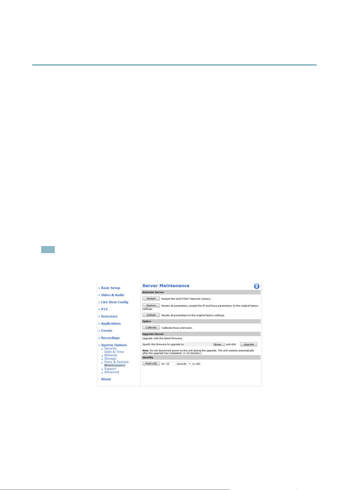
AXIS P3364–V
Troubleshooting
Troubleshooting
Checking the Firm ware
Firmware is software that determines the functionality of network devices. One of your first actions when troubleshooting a problem
should be to check the current firmware version. The latest version ma y contain a correction that fi xesyourparticularproblem.The
current firmware version in the A xis prod uct is displa yed in the page Setup > Basic Setup and in Setup > About.
Upgrading the Firmware
When you upgrade the product with the latest firmw a re fr om Axis website, the product receives the latest functionality avail able .
Always read the upgrade instructions and release notes available with each new release, before upgra ding the firmware.
To upgrade, follow these instructions:
1. Save the firmware file to your computer. The latest version of the firmware is available free of charge from Axis webs ite
at www.axis.com/techsup
2. Go to Setup > System Options > Maintenance in the products web pages.
3. Under Upgrade Server, click Browse and locate the file on your computer . Click Upgrade.
After starting the upg rade process, always wait at least 5–10 minutes before restarting the product, even if you suspect the
upgrade has failed.
AXIS Camera Management can be us ed f or m ultiple upgrades. See www.axis.com for more information.
Note
• Your dealer reserves the right to charge for any repair attributable to faulty upgrade by the user.
•Preconfigured and customized settings are saved when the firmware i s upgraded
(providing the features are available in
the new firmware) although this is not guaranteed by A xis Communications AB.
Emergency Recovery Procedure
If power or network connection is lost during the upgrade, the process fails and the product becomes unresponsive. Flashing red Status
indicator indicates a failed upgrade. To recover the product, follo w the steps below. The serial number is found on the pro duct’s label.
1. In UNIX/Linux, type the following from the com m and line:
51

AXIS P3364–V
Troubleshooting
arp -s <IP address> <serial number> temp
ping -s 408 <IP address>
In Windows, type the following from a co mmand/DOS prompt (this may require that you run the command prompt as
an administra tor):
arp -s <IP address> <serial number>
ping -l 408 -t <IP address>
2. If the product does not rep ly in 30 seconds, restart it and wait for a reply. Press CTRL+C to stop Ping.
3. Open a browser and type in the product’s IP address. In the page that appears, use the Browse button to select the upgrade
file to use. Then click Load to restart the upgrade process.
4. After the upgrade is complete (1–10 minutes), the product automatically restarts and shows a steady green on the Status
indicator.
5. Reinstall the product, referring to the Installation Guide.
If the emergency recovery procedure does not get the product up and running again, contact A xis support at www.axis.com/techsup/
Symptoms, Possible Causes and Rem edial Actions
Problems setting the IP address
When using ARP/Ping
Try the installation again. The IP addres s must be set within two minutes after power has been
applied to the product. Ensure the Ping length is set to 408. See the Installation Guide for
detailed instructions.
The product is located on a
different s ubnet
If the IP address intended for the product and the IP address of the computer used to access the
product are located on different subnets, you w ill not be able to set the IP address. Contact y our
network administrator to obtain an IP address.
The IP address is be ing used
by another device
Disconnect the Axis p roduct from the network. Run the Ping command (in a Command/DOS
window, type ping and the IP ad dress of the product:
•Ifyoureceive:Reply from <IP address>: bytes=32; time=10...
this means that the IP address may already be in use by another device on the network.
Obtain a new IP address from the network administrator and reinstall the product.
•Ifyoureceive:Request timed out, this means that the IP address is available for
use with the Axis product. Check all cabling and reinstall the product.
Possible IP address conflict
with another device on the
same subnet.
The static IP address in the Axis product is used before the DHCP server sets a dynamic address .
This means that if the same default static IP addressisalsousedbyanotherdevice,theremay
be pro blems accessing the product.
The product cannot be a ccessed from a browser
Cannot log in
When HTTPS is enabled, ensure that the correct protocol (H TTP or HTTPS) is used when attempting
to log in. You m
ay need to manually type http or https in the browser’s address field.
If the pa s
sword for root is lost, the pro duct must be reset to the factory default settings. See
Reset to Factory Default Settings, on page 49
.
52

AXIS P3364–V
Troubleshooting
The IP address has been
changed by DHCP
If the product and the client are on the same network, run AX IS IP Utility to locate the pro d uct.
Identify the product using its model or serial number.
Move the Axis product to an isolated netwo rk, or to one with no DHCP or BOOTP server. Set the IP
address again, using AXIS IP U tility or ARP/Ping (see the Installation Guide). Open the Setup pages
and disabled DHCP in the TCP/IP settings. Return the product to the main n etw ork. The product
now has a fixed IP address that w ill not change.
Certificate error when using
IEEE 802.1X
For authentication to work properly, the date and time settings in the Axis product should be
synchronized with an NTP server. See
Date & Time, on page 41
.
The product is accessible locally but not externa lly
Router configuration To con fig ure your router to allow incoming data traffic to the Axis product, enable the NAT-traversal
feature which w ill attempt to automatically configure the router to allow access to the Axis
product, see
NAT traversal (port mapping) for IPv4, on page 44
. The router must support UPnP
TM
.
Firewall protection
Check the Internet firew all with yo ur network administr ator.
Default routers required
Check if you need to configure the router settings.
Problems with the H.264 format
No H.264 displayed in the
client
Check that the relevant H.264 connection m ethods an d corr ect interf ace a re ena b le d in the AMC
Control Pan el (streaming tab). See
AXIS Media Control (AMC), on page 12
.
In the AM C Control Panel, select the H.264 tab and click Set to default H.264 decoder.
Check that RTSP is enabled under System Options > Network > TCP/IP > Advanced.
No multicast H.264
displayed in the cl ient
Check with your network administrator that the multicast addresses used by the Axis product
arevalidforyournetwork.
Check with your network administrator to see if there is a firewall preventing viewing.
Multicast H.264 only
accessible by local clients
Check if your router supports multicasting, o r if the router set
tings between the client and the
product need to be configu red . The TTL (Time To Live) value may need to be increase d.
Poor rendering of H .264
images
Color depth set incorrectly on clients. Set to 16–bit or 32–bit color.
If text overlays are blurred, or if there a re other rendering problems, you may need to enable
Advanced Video Rend ering from
v the Video tab in the AMC Control Panel.
Ensure that your gr aphic
s card is using the latest driver. The latest drivers can u sua lly be
downloaded fro m the manufacturer’s website.
Color saturation is diffe re nt
in H.264 and Mo
tion JPE G
Modify the settings for your graphics adapter. Refer to the adapter’s documentation for more
information.
Lower frame rate than
expected
Reduce the number of a pplications running on the client computer.
Limit the number of simultaneous viewers.
Check with the network administrator that there is enough band wid th availa ble.
Check in the AMC Control Panel (H.264 tag) that video processing is NOT set to Decode only
key frames.
Lower the im age resolution.
53

AXIS P3364–V
Troubleshooting
Why do I not get maximum
frames per second?
See
Performance Considerations, on page 58
.
The max imum frames per second is depende nt on the utility frequen cy (60/50 Hz) of the Axis
product. S ee
Technical Specification s, on page 56
.
Image degeneration
Decrease the GOV length. Go to Video & Audio > Video Stream and select the H.264 tab
to modify the GOV length.
Status and Network indicator LEDs are flashing red rapidly
Hardware failure
Contact your Axis res eller.
Status indicator LED is flashing red a nd the product is inaccessible
A firmwar e upg rade h a s
been interrupted or the
firmware has otherwise been
damaged
See
Emergency Recovery Procedure, on page 51
.
No images displayed on web page
Problems with AXIS Media
Control (
Internet Explorer
only
)
To enable the updating of video images in Internet Explorer, set the browser to allow A c tiveX
controls. Also, make s ure that AXIS Media Contr ol is insta lle d on your computer.
Installation of additional
ActiveX component
restricted or prohibited
Configure the Axis product to use a Java applet for updating video images in Internet Explorer. Go
to Setup > Live View Config and select Java applet under Default viewer.
Video and image problems, general
Image too dark or too light
Check the video stream and camera settings under Setup > Video & Audio > Video Stream and
Setup > Video & Aud io > Camera Settings.
Missing images in uploads This can occur when trying to use a larger image buffer than is actually available. Try lowering
the fra me rate or the uploa d period.
Slow image update Configuring pre-buffe rs , m oti on de tection, high-resolution ima g es o r hig h fr am e ra tes w il l affe ct
the p erform a n ce of the Axis prod u ct.
Poor performance Poor performance may be caused by heavy netw ork traffic, multiple users accessing the product,
low performance clients, use of fea ture s such as motion detection, event handling or uploaded
applications.
Poor quality snapshot images
Screen incorrectly
configured on your computer
Configure your screen to show at least 65000 colors, that is, at least 16 bits. Using only 16 or 256
colors will produce dithering artifacts in the image.
Overlay image is not displayed
Incorrect size or location of
overlay image
The overlay image may have been positioned incorrectly or m ay be too large. See
Overlay Image
Settings
in the online help for more information.
Privacy mask is n ot displayed
Incorrect size or location of
privacy mask
The privacy mask may have been positioned incorrectly or may be too large.
54

AXIS P3364–V
Troubleshooting
Browser freezes
Firefox can sometimes
freeze on a slow computer
Lower the im age resolution
Problems uploading files
Limited space There is only limited space available for the upload of your own files. Delete existing files to free
up space.
Motion Detection triggers unexpectedly
Changes in luminance
Motion detection is based on changes in luminance in the image. This means that if there are
sudden changes in the lighting, motion detecti on may trigger mistakenly. Lower the sensitivity
setting to avoid problems w ith luminance.
No audio
Incorrect setup
Check the sound card in the computer. Ensure th at mute is not selected and that the volume
settings are correct.
No audio or very poor audio
quality
Check that Enable audio support is selected under Setup > System Options > Security > Audio
Support.
Check that the correct Audio Input source is selected under Setup > Video & Audio > Audio
Settings.
Poor audio quality
CPU overloaded
Reduce the number of listeners and viewers. Decrease image resolution and compression.
Unsynchronized audio and
video
Synchronize the product’s date and timesettingswithanNTPserver. GotoSetup > System
Options > Date & Time.
Distorted audio
Check that the correct Audio Input source is selected under Setup > Video & Audio > Audio
Settings.
Feedback loops Feedback loops might appear in full-duplex mode. Try moving the microphone or the speaker, or
use half-duplex mod e instead.
Storage and disk management problems
Video cannot be recorded
Check that the SD card is not write protected (that is, read only).
SD card cannot be mounted Reformat the SD card and then click Mount.
55

AXIS P3364–V
Technical Specifications
Technical Specifications
Function/group
Item
Specifications
Models
AXIS P3364–V
Image sensor
Progressive scan RGB CMOS 1/3”
Lens Varifocal, remote focus and zoom, P-iris, IR correcte d, me xa pix el resolution
6 m m models: 2.5-6 mm, F1.2, horizontal angle of view: 110°-47°,vertical angle of view:
82°-36°, diagonal angle of view: 124° - 54° Varifocal, P-iris, remote focus and zoo m
12 mm models: 3.3-12 mm, F1.4, horizontal angle of view: 88°- 25°, vertical angle of
view: 63°-18°, diagonal angle of view: 100° - 32°
Minimum
illumination
6 mm m odels: Color: 0.2 lux, F1.2, B/W: 0.04 lux, F1.2 12 mm models: Color: 0.3 lux,
F1.4, B/W: 0.05 lux, F1.4
Shutter time
Capture frequency 50 Hz: 1/24500 s to 2 s
Capture frequency 60 Hz: 1/29500 s to 2 s
Pan/Tilt/Zoom
Digital PTZ, preset positions, guard tour
Camera angle
adjustment
Pan 360°, tilt 170°, rotation 340°
Video
compression
H.264 Baseline and Main Profile (MPEG-4 Part 10/AVC)
Motion JPEG
Resolutions
800 x 600 to 160 x 90
Frame rate H.264
25 fps with Capture frequency 50 Hz, 30 fps with Capture frequency 60 Hz
Frame rate
Motion JPEG
25 fps with Capture frequency 50 Hz, 30 fps with Capture frequency 60 Hz
Video streaming
Multi-stream H.264 and Motion JPEG
Controllable frame rate and bandwi dth
VBR/CBR H.264
H.264: 2 individually configured streams in HDTV 720p
and full frame rate
Motion JPEG: 2 individually configured streams in HDTV 720p and full frame rate 1 H.264
and 1 Motion JPEG streams in HDTV 720p and full frame rate More streams if identical or
limited in frame rate or resolutio
n
Image settings
Compression, color, brightness, sharpness, contrast, white balance, exposure control,
exposure zones, backlight compensation, fine tuning of behavior at different light levels,
wide dynamic range - dyn
amic contrast Ro tation: 0°, 90°, 180°, 270°, including Corridor
Format
Text and image overlay, priva c y mask and mirroring of images
Video
Users Up to 20 simultaneous unicast connections Unlimited number of users using multicast
(H.264)
Audio streaming Two-way, full duplex
Audio
compression
AAC LC 8/16 kHz, G.711 PCM 8 kHz, G.726 ADPCM 8 kHz Configurable bit rate
Audio
Audio
input/output
External microphone input or line input, line level output
Built-in microphone. Plugging the audio input jack disables the internal microphone
56

AXIS P3364–V
Technical Specifications
Function/group
Item
Specifications
Security Password protection, IP address filtering, HTTPS encryption*, IEEE 802.1X network access
control*, digest authentication, user access log
Network
Supported
protocols
IPv4/v6, HTTP, HTTPS, SSL/TLS*, QoS Layer 3 DiffServ, FTP, SMTP, Bonjour, U PnP,
SNMPv1/v2c/v3(MIB-II), DNS, DynDNS, NTP, RTSP, RTP, TCP, UDP, IGMP, RTCP, ICMP,
DHCP,ARP,SOCKS,etc. *Thisproductincludes software developed by the Open SSL
Project for use in the Open SSL Tool kit (www.openssl.org)
Application
Programming
Interface
Open API for software integration, including the ONVIF specification available at
www.onvif.org, as well as VAPIX® and AXIS Camera Application Platform from Axis
Communicati ons, specifications available at www.axis.com Support f or AXIS Video
Hosting System (AVHS) with One-Click Camera co nnection
Intelligent video Video motion detection, active tampering alarm
Support for AXIS Camera Application Platform enabling installation of additional
applications Audio detection
Events Intelligent video
External input
Alarm actions
File upload via FTP, HTTP and email Notification via email, HTTP and TCP Video recording
to edge storage Pre- and post-alarm video buffering
Day/Night switching Status LED activation
External output a ctivation, audio recording to e dge storag e, playing aud io clips
Video access from
web browser
Camera live view
Video recording to file (ASF)
Customizable HTM L pag es
Windows 7, Windows Vista, Windows XP, Windows Server 2008, Windows Server 2003
DirectX 9c or higher
For other operating systems a nd browsers, see www.axis.com/techsup
System
integration
Installation,
management and
maintenance
AXIS Camera Management tool on CD and web-based configuration
Configuration of backup and restore
Firmware upgrades over HTTP or FTP, firmware available on www.axis.com
Casing
Aluminum inner camera module with encapsulated electronics
IK10 impact-resistant casing with metal base and rugged polycarbonate transparent cover
Color: White NCS S 1002-B
Processor,
memory
ARTPEC-4, 256 MB RAM, 128 MB Flash
Battery backed-up real-time clock
Power Power over Ethernet IEEE 802.3af
Class 2; m ax:5.9W
Connectors
RJ-45 10BASE-T/1
00BASE-TX Po E
Terminal block for 1 alarm input and 1 output 3.5 mm jack for mic in (max 80 mVpp)
or line mono input (max 6.4 Vpp) 3.5 mm jack for Line mono output (max 1.3 Vpp) to
active sp
eaker
Edge storage
SD/SDHC memory card slot (card not included)
Support for recording to network share (Network Attached Storage or file server)
Operating
conditions
0 to 50 °C (32 to 122 °F), humidity 10 - 85% RH (non-condensing)
Storage
temperature
-40 to 70 °C (-40 to 158 °F)
Approvals
CE: Emission: EN55022:2006+A1 Class B Harmonics: EN61000-3-2 Flicker: EN61000-3-3
Immunity: EN55024, EN61000-6-1, EN61000-6-2 Safety: : IEC/EN 60950-1
FCC: FCC Part 15, Subpart B, Class B demonstrated by compliance with EN55022 (CISPR
22)
General
57

AXIS P3364–V
Technical Specifications
Function/group
Item
Specifications
Japan: VCCI-2008, Class B, ITE • C-tick AS/NZS CISPR 22, demonstrated by compliance
with EN55022 (CISPR 22)
Canada: ICES-003 Canadian ICES-003, Class B digital, demonstrated by compliance
with EN55022 (CISPR 22)
Environmental: IEC 60068-2-1, IEC 60068-2-2, IEC 60068-2-14, IEC 60068-2-27, IEC
60068-2-64, IEC 60068-2-78, IEC 62262 IK10
Dimensions
(HxWxD)
97 x 148 x 148 mm (3.82 x 5.83 x 5.83")
Weight
650 g (1.4 lb.)
Included
accessories
Installation Guide, CD with installation tools, recording software and User’s Manual,
Windows decoder 1-user license
Smoked transparent cover
Connector kit
Video
management
software (not
included)
AXIS Camera Station - Video management software for viewing and recording up to 100
cameras
See www.axis.com/products/video/software/ for more software applications via partners
Optional
accessories
AXIS Illuminators
AXIS T91A brackets
IP51-rated drop-ceiling mount kit with transparent or smoked cover
Pendant adapter kit
Mounting bracket
Performance C onsiderations
When settings up your system, it is important to consider how various setting s and situations will affect perfor m ance. Some factors
affect the amount of bandwidth (the bit rate) required, others can affect the frame rate , and some affect both. If the load on the
CPU reaches its maximum, this will a lso affect the fra m e rate.
The following factors are among the most important to consider:
• High image resolution and/or lower compression levels result in images containing more data. Bandwidth affected.
• Access by large numbers of Motion JPEG and/or unicast H.264 clients. Bandwidth affected.
• Simultaneous viewing of different streams (resolution, compression) by different clients. Effect on frame rate and bandwidth.
• Accessing Motion JPEG and H.264 video stre ams s imultane ous ly. Frame rate and bandwidth affe cted.
• Heavy usage of event settings a ffect the product’s CPU load. Frame rate affected.
• Heavy network utilization due to poor infrastructure. Ba ndw idth affected.
• Viewing on poorly performing client computers lowers perceived performance. Frame rate affected.
58

User Manual Ver. M1.10
AXIS P3364–
V Date: March 2012
© Axis Communications AB, 2012
Part No. 45
402