
For domestic household use only.
INSTRUCTION MANUAL
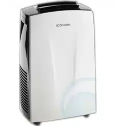
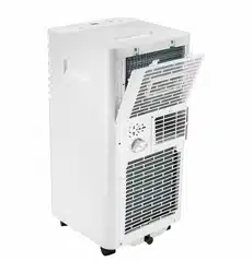
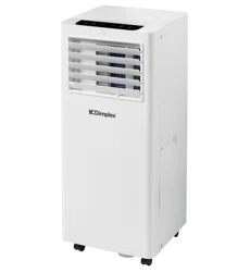
2.6kW Portable Air Conditioner
Model: DCP9C

IMPORTANT
THESE INSTRUCTIONS SHOULD BE READ CAREFULLY
AND RETAINED FOR FUTURE REFERENCE. Note also the
information presented on the appliance
CAUTION: FAILURE TO FOLLOW THESE INSTRUCTIONS MAY CAUSE INJURY AND/
OR DAMAGE AND MAY INVALIDATE YOUR WARRANTY
Please read the operating instructions carefully before using your Portable Air
Conditioner for the first time and keep them in a safe place.
WARNING – This appliance must not be used in a bathroom.
WARNING – Do not use this appliance in the immediate surroundings of a bath, a
shower or a swimming pool.
• If the mains lead is damaged it must only be replaced by the manufacturers service
agent or a similarly qualified person in order to avoid a hazard.
• This appliance is not intended for use by persons (including children) with
reduced physical, sensory or mental capabilities, or lack of experience and
knowledge, unless they have been given supervision or instruction concerning use
of the appliance by a person responsible for their safety.
• Children should be supervised to ensure they do not play with the appliance.
• Prior to cleaning or other maintenance, the appliance must be disconnected from
the supply mains.
• Never immerse the appliance in water or other liquids.
• Operate this unit only on a firm, flat surface to avoid the risk of water leakage.
Ensure that the unit is kept upright at all times.
• Do not place on soft, unstable or non-horizontal/angled surfaces.
• Never operate the appliance if a cable or connector has been damaged, after
appliance malfunction or if the appliance was dropped or is otherwise damaged.
• Please ask a professional service agent to repair the product. Improper repair may
cause danger to users.
• Disconnect the appliance from mains power whenever it is not in use, before
relocating it, and before cleaning.
• Operate the appliance only at the voltage specified on the rating label.
• Only connect the unit to a properly installed and easily accessible socket so that
you can quickly disconnect the plug if necessary.
• Do not connect this product to the mains using an extension lead.
• This product is only intended for INDOOR RESIDENTIAL applications. This product
should not be used for commercial or industrial or leisure applications or in small
enclosed spaces.
• Never use the mains lead as a carrying strap or pulling lead.
• To avoid a fire or electrocution hazard, NEVER put the cord near heat registers,
radiator, stoves or heaters.
• DO NOT cover cord with carpeting, throw rugs, runners, or similar coverings.
• DO NOT route cord under furniture or appliances. Take care to position the cord
away from trac areas and where it will not be a tripping hazard.
• DO NOT use the unit near windows or where water collects. Rain and water collection
2

may lead to a risk of fire or electric shock.
• Only operate this appliance with a minimum of 50cm clearance all around i.e. away
from walls, furniture and overhanging objects such as curtains or a shelf.
• WARNING: To avoid danger of suocation please remove all packaging materials
particularly plastic and EPS and keep these away from vulnerable people, children
and babies.
• NEVER drop or insert any object or fingers into any openings.
• Do not cover or obstruct the air inlet and outlets.
• Do not use the appliance in locations where paint, petrol or other flammable liquids
are used or stored.
• Do not use bug sprays or other flammable cleansers/vapour sprays on or around
the unit.
• Always switch o the unit and take the plug out of the socket:
•
If you are not using the unit
•
Before you clean or carry out maintenance on the unit
•
If a fault occurs
•
In the event of an electrical storm.
• Avoid electromagnetic interference. Keep the unit at least 1 metre away from
electrical appliances such as televisions & radios.
• The air conditioner must always be stored and transported upright. In case of doubt
we suggest you wait for at least 24 hours before operation. (Please keep unit upright
at all times).
• This portable air conditioner is fitted with a compressor delay protection circuit.
This protects the unit from possible damage due to rapid starting and stopping of
its compressor. The compressor will begin operationg 3 minutes after the unit has
been switched ON or if the mode is changed from dehumidify to cooling.
• It is hazardous for anyone other than an Authorised Service Person to service this
appliance. In Queensland - the authorised Service Person MUST hold a Gas Work
Authorisation for hydrocarbon refrigerants to carry out servicing or repairs where
the gas system is being opened or charged.
• This appliance shall be installed in accordance with national wiring regulations.
3
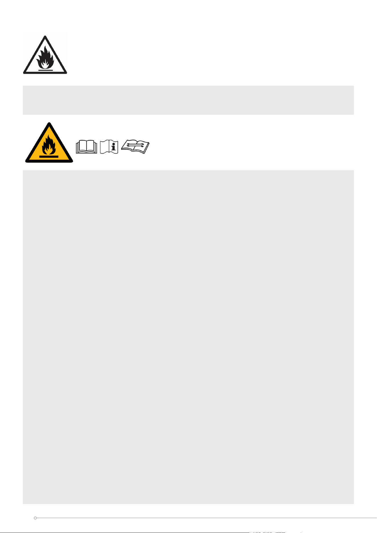
WARNING: For using R290 refrigerant.
ThIs symbol shows that
this appliance uses a flammable refrigerant. If the refrigerant
is leaked and exposed to an external ignition source, there is a
risk of fire.
CAUTION: RISK OF FIRE/FLAMMABLE MATERIALS. THE APPLIANCE MUST BE
INSTALLED, USED & STORED IN AN AREA THAT IS GREATER THAN 9m².
NB: These symbols on your device mean:
• This appliance is filled with Propane gas R290. Follow strictly the manufacturer's
instruction concerning use and repairs!
• Before using this appliance, you must carefully read the entire instruction manual.
• Do not install, operate or store the device in a room with a floor area smaller than
9m².
• Repairs must be performed based on the recommendations from the
manufacturing company.
• Note also the information presented on the appliance.
• Do not use means to accelerate the defrosting process or to clean, other than those
recommended by the manufacturer.
• The appliance shall NOT be stored in a room with continuously operating ignition
sources (for example: open flames, an operating gas appliance or an operating
electric heater).
• Do not pierce or burn.
• Be aware that the refrigerants may not contain an odour.
• The appliance should be installed, operated and stored in a room with a floor area
according to the amount of refrigerant to be charged. For specific information on
the type of gas and the amount, please refer to the relevant label on the unit itself.
When there are dierences between the lable and the manual on the Min. room area
description, the description on label shall prevail.
• Compliance with national gas regulations shall be observed.
• Keep ventilation openings clear of obstruction.
• The appliance shall be stored so as to prevent mechanical damage from occurring.
• A warning that the appliance shall be stored in a well-ventilated area where the
room size corresponds to the room area as specified for operation.
• Any person who is involved with working on or breaking into a refrigerant circuit
should hold a current valid certificate from an industry-accredited assessment
authority, which authorises their competence to handle refrigerants safely in
accordance with an industry recognised assessment specification.
• Servicing shall only be performed as recommended by the equipment manufacturer.
Maintenance and repair requiring the assistance of other skilled personnel shall be
carried out under the supervision of the person competent in the use of flammable
refrigerants.
4

1. Transport of equipment containing flammable refrigerants - see transport
regulations
2. Marking of equipment using signs - see local regulations
3. Disposal of equipment using flammable refrigerants - see national regulations.
4. Storage of equipment/appliances - The storage of equipment should be in
accordance with the manufacturer's instructions.
5. Storage of packed (unsold) equipment - storage package protection should be
constructed such that mechanical damage to the equipment inside the package
will not cause a leak of the refrigerant charge. The maximum number of pieces
of equipment permitted to be stored together will be determined by local
regulations.
6. Information on servicing
• Checks to the area
Prior to beginning work on systems containing flammable refrigerants, safety
checks are necessary to ensure that the risk of ignition is minimised. For repair to
the refrigerating system, the following precautions shall be complied with prior to
conducting work on the system.
• Work procedure
Work shall be undertaken under a controlled procedure so as to minimise the risk
of a flammable gas or vapour being present while the work is being performed.
• General work area
All maintenance sta and others working in the local area shall be instructed on
the nature of work being carried out. Work in confined spaces shall be avoided.
The area around the workspace shall be sectioned o. Ensure that the conditions
within the area have been made safe by control of flammable material.
• Checking for presence of refrigerant
The area shall be checked with an appropriate refrigerant detector prior to
and during work, to ensure the technician is aware of potentially flammable
atmospheres. Ensure that the leak detection equipment being used is suitable
for use with flammable refrigerants, i.e. non-sparking, adequately sealed or
intrinsically safe.
• Presence of fire extinguisher
If any hot work is to be conducted on the refrigeration equipment or any
associated parts, appropriate fire extinguishing equipment shall be available to
hand. Have a dry powder or CO2 fire extinguisher adjacent to the charging area.
• No ignition sources
No person carrying out work in relation to a refrigeration system which involves
exposing any pipe work that contains or has contained flammable refrigerant
shall use any sources of ignition in such a manner that it may lead to the risk of
fire or explosion. All possible ignition sources, including cigarette smoking, should
be kept suciently far away from the site of installation, repairing, removing and
disposal, during which flammable refrigerant can possibly be released to the
surrounding space. Prior to work taking place, the area around the equipment is
to be surveyed to make sure that there are no flammable hazards or ignition risks.
No Smoking signs shall be displayed.
• Ventilated area
Ensure that the area is in the open or that it is adequately ventilated before
breaking into the system or conducting any hot work. A degree of ventilation
shall continue during the period that the work is carried out. The ventilation
should safely disperse any released refrigerant and preferably expel it externally
into the atmosphere.
5

• Checks to the refrigeration equipment
Where electrical components are being changed, they shall be fit for the purpose
and to the correct specification. At all times the manufacturer's maintenance
and service guidelines shall be followed. If in doubt consult the manufacturer's
technical department for assistance. The following checks shall be applied to
installations using flammable refrigerants:
The charge size is in accordance with the room size within which the refrigerant
containing parts are installed;
The ventilation machinery and outlets are operating adequately and are not
obstructed;
If an indirect refrigerating circuit is being used, the secondary circuit shall be
checked for the presence of refrigerant; Marking to the equipment continues to
be visible and legible. Markings and signs that are illegible shall be corrected;
Refrigeration pipe or components are installed in a position where they are
unlikely to be exposed
to any substance which may corrode refrigerant containing components, unless
the components are constructed of materials which are inherently resistant to
being corroded or are suitably protected against being so corroded.
• Checks to electrical devices
Repair and maintenance to electrical components shall include initial safety
checks and component inspection procedures. If a fault exists that could
compromise safety, then no electrical supply shall be connected to the circuit
until it is satisfactorily dealt with. If the fault cannot be corrected immediately
but it is necessary to continue operation, an adequate temporary solution shall
be used. This shall be reported to the owner of the equipment so all parties are
advised.
Initial safety checks shall include:
That capacitors are discharged: this shall be done in a safe manner to avoid
possibility of sparking; That there no live electrical components and wiring
are exposed while charging, recovering or purging the system; That there is
continuity of earth bonding.
• Repairs to sealed components
• During repairs to sealed components, all electrical supplies shall be disconnected
from the equipment being worked upon prior to any removal of sealed covers,
etc. If it is absolutely necessary to have an electrical supply to equipment during
servicing, then a permanently operating form of leak detection shall be located at
the most critical point to warn of a potentially hazardous situation.
• Particular attention shall be paid to the following to ensure that by working on
electrical components, the casing is not altered in such a way that the level of
protection is aected. This shall include damage to cables, excessive number
of connections, terminals not made to original specification, damage to seals,
incorrect fitting of glands, etc. Ensure that apparatus is mounted securely. Ensure
that seals or sealing materials have not degraded such that they no longer serve
the purpose of preventing the ingress of flammable atmospheres. Replacement
parts shall be in accordance with the manufacturer's specifications.
NOTE: The use of silicon sealant may inhibit the eectiveness of some types
of leak detection equipment. Intrinsically safe components do not have to be
isolated prior to working on them.
6

• Repair to intrinsically safe components
Do not apply any permanent inductive or capacitance loads to the circuit without
ensuring that this will not exceed the permissible voltage and current permitted
for the equipment in use. Intrinsically safe components are the only types that
can be worked on while live in the presence of a flammable atmosphere. The test
apparatus shall be at the correct rating. Replace components only with parts
specified by the manufacturer. Other parts may result in the ignition of refrigerant
in the atmosphere from a leak.
• Cabling
Check that cabling will not be subject to wear, corrosion, excessive pressure,
vibration, sharp edges or any other adverse environmental eects. The check
shall also take into account the eects of aging or continual vibration from
sources such as compressors or fans.
• Detection of flammable refrigerants
Under no circumstances shall potential sources of ignition be used in the
searching for or detection of refrigerant leaks. A halide torch (or any other
detector using a naked flame) shall not be used.
• Leak detection methods
The following leak detection methods are deemed acceptable for systems
containing flammable refrigerants. Electronic leak detectors shall be used to
detect flammable refrigerants, but the sensitivity may not be adequate, or may
need re-calibration. (Detection equipment shall be calibrated in a refrigerant-free
area.) Ensure that the detector is not a potential source of ignition and is suitable
for the refrigerant used. Leak detection equipment shall be set at a percentage of
the LFL of the refrigerant and shall be calibrated to the refrigerant employed and
the appropriate percentage of gas (25 %maximum) is confirmed. Leak detection
fluids are suitable for use with most refrigerants but the use of detergents
containing chlorine shall be avoided as the chlorine may react with the refrigerant
and corrode the copper pipe-work. If a leak is suspected, all naked flames shall be
removed/ extinguished. If a leakage of refrigerant is found which requires brazing,
all of the refrigerant shall be recovered from the system, or isolated (by means
of shut o valves) in a part of the system remote from the leak. Oxygen free
nitrogen (OFN) shall then be purged through the system both before and during
the brazing process.
• Removal and evacuation
When breaking into the refrigerant circuit to make repairs or for any other
purpose conventional procedures shall be used. However, it is important that
best practice is followed since flammability is a consideration. The following
procedure shall be adhered to: Remove refrigerant; Purge the circuit with inert
gas; Evacuate; Purge again with inert gas; Open the circuit by cutting or brazing.
The refrigerant charge shall be recovered into the correct recovery cylinders. The
system shall be flushed with OFN to render the unit safe. This process may need
to be repeated several times. Compressed air or oxygen shall not be used for
this task. Flushing shall be achieved by breaking the vacuum in the system with
OFN and continuing to fill until the working pressure is achieved, then venting to
atmosphere, and finally pulling down to a vacuum. This process shall be repeated
until no refrigerant is within the system. When the final OFN charge is used, the
system shall be vented down to atmospheric pressure to enable work to take
place. This operation is absolutely vital if brazing operations on the pipe-work
are to take place. Ensure that the outlet for the vacuum pump is not close to any
ignition sources and there is ventilation available.
7

• Charging procedures
In addition to conventional charging procedures, the following requirements shall
be followed. Ensure that contamination of dierent refrigerants does not occur
when using charging equipment. Hoses or lines shall be as short as possible to
minimise the amount of refrigerant contained in them.
Cylinders shall be kept upright.
Ensure that the refrigeration system is earthed prior to charging the system with
refrigerant.
Label the system when charging is complete (if not already).
Extreme care shall be taken not to overfill the refrigeration system. Prior to
recharging the system it shall be pressure tested with OFN. The system shall be
leak tested on completion of charging but prior to commissioning. A follow up
leak test shall be carried out prior to leaving the site.
• Decommissioning
Before carrying out this procedure, it is essential that the technician is completely
familiar with the equipment and all its detail. It is recommended good practice
that all refrigerants are recovered safely. Prior to the task being carried out, an oil
and refrigerant sample shall be taken in case analysis is required prior to re-use
of reclaimed refrigerant. It is essential that electrical power is available before the
task is commenced.
a) Become familiar with the equipment and its operation.
b) Isolate system electrically.
c) Before attempting the procedure ensure that: Mechanical handling
equipment is available, if required, for handling refrigerant cylinders;All personal
protective equipment is available and being used correctly; The recovery
process is supervised at all times by a competent person; Recovery equipment
and cylinders conform to the appropriate standards.
d) Pump down refrigerant system, if possible.
e) If a vacuum is not possible, make a manifold so that refrigerant can be
removed from various parts of the system.
f) Make sure that cylinder is situated on the scales before recovery takes place.
g) Start the recovery machine and operate in accordance with manufacturer's
instructions.
h) Do not overfill cylinders. (No more than 80 % volume liquid charge).
i) Do not exceed the maximum working pressure of thecylinder, even
temporarily.
j) When the cylinders have been filled correctly and the process completed,
make sure that the cylinders and the equipment are removed from site
promptly and all isolation valves on the equipment are closed o.
k) Recovered refrigerant shall not be charged into another refrigeration system
unless it has been cleaned and checked.
• Labelling
Equipment shall be labelled stating that it has been de-commissioned and
emptied of refrigerant. The label shall be dated and signed. Ensure that there are
labels on the equipment stating the equipment contains flammable refrigerant.
8

• Recovery
When removing refrigerant from a system, either for servicing or
decommissioning, it is recommended good practice that all refrigerants are
removed safely. When transferring refrigerant into cylinders, ensure that only
appropriate refrigerant recovery cylinders are employed. Ensure that the correct
number of cylinders for holding the total system charge is available. All cylinders
to be used are designated for the recovered refrigerant and labelled for that
refrigerant (i.e. special cylinders for the recovery of refrigerant). Cylinders shall
be complete with pressure relief valve and associated shut-o valves in good
working order. Empty recovery cylinders are evacuated and, if possible, cooled
before recovery occurs. The recovery equipment shall be in good working order
with a set of instructions concerning the equipment that is at hand and shall be
suitable for the recovery of flammable refrigerants. In addition, a set of calibrated
weighing scales shall be available and in good working order. Hoses shall be
complete with leak-free disconnect couplings and in good condition. Before using
the recovery machine, check that it is in satisfactory working order, has been
properly maintained and that any associated electrical components are sealed
to prevent ignition in the event of a refrigerant release. Consult manufacturer if
in doubt. The recovered refrigerant shall be returned to the refrigerant supplier
in the correct recovery cylinder, and the relevant Waste Transfer Note arranged.
Do not mix refrigerants in recovery units and especially not in cylinders. If
compressors or compressor oils are to be removed, ensure that they have been
evacuated to an acceptable level to make certain that flammable refrigerant
does not remain within the lubricant. The evacuation process shall be carried
out prior to returning the compressor to the suppliers. Only electric heating to
the compressor body shall be employed to accelerate this process. When oil is
drained from a system, it shall be carried out safely.
9
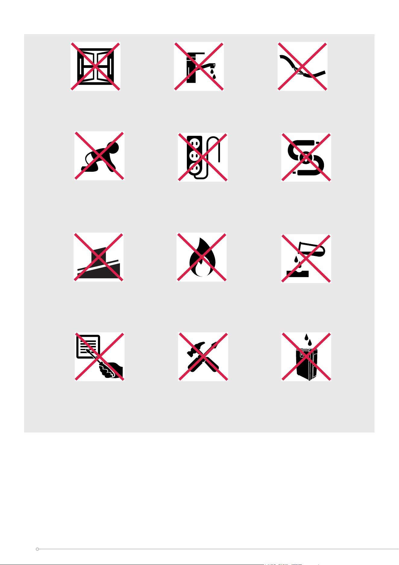
Exposed to the
weather outdoors
Near water If the power cable
wires are frayed or cut
Where small children
may be left unattended
No extension leads or
power boards
Where there is risk
of fire or close to
a naked flame
Where the power
cable may be
damaged
On a slope or
uneven surface
Where it may be
damaged by
chemicals
If there is a risk
of water falling on
the unit
Where there is a risk
of interference by
foreign objects
This product is not
made for DIY repair
10

Model no. DCP9C
Colour
White
Power supply
220-240V~50Hz
Operating temperature
17-35°C
Thermostat range
17-30°C
Rated Input Power
1.3kW
Cooling Capacity
2.6kW
Noise Level Minimum (Lo) 51dB(A)
Noise Level Maximum (Hi)
54dB(A)
Air Volume (Lo/Hi)
260/320
Refrigerant
R290
Fan speeds
2
Modes
Cool, Dry & Fan
Timer
24 hours
Dimensions (w x d x h)
280 x 290 x 675mm
Min room size 9m
2
Max room size 20m
2
Weight net 20.8kg
Weight gross
27kg
Specification
• For greater precision, please always refer to the rating label placed on the product.
11
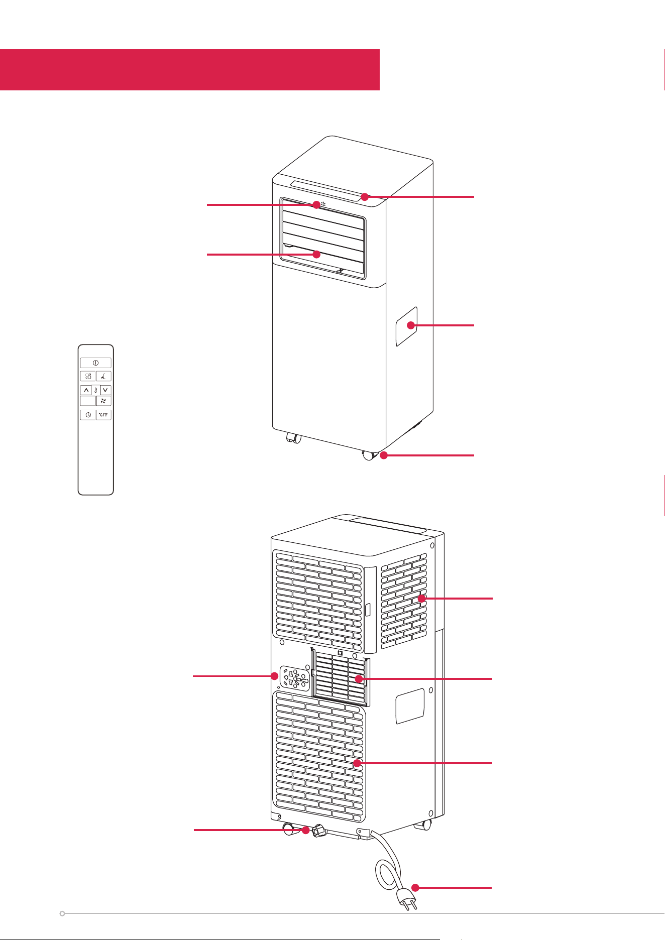
Plug fixer
Drain outlet
Lower air
intake
Air outlet
Upper air
intake
Power cord
Parts
Deflector
Remote
Handle
Control panel
Castors
Remote control
receiver
12
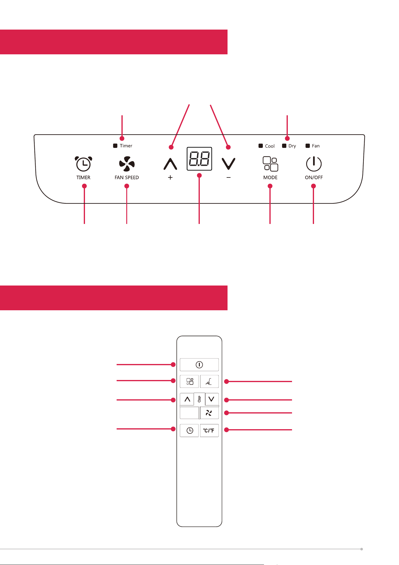
Control Panel
Remote Control
Sleep
Decrease
Fan speed control
Unit switch
Increase
Timer
Mode
On/O
Temp Adjustment
Up (+) and Down (-)
Timer Fan
Mode
Cool, Fan, Dry
On/Off
Display
Screen
Timer
Indicator
Mode
Indicators
13
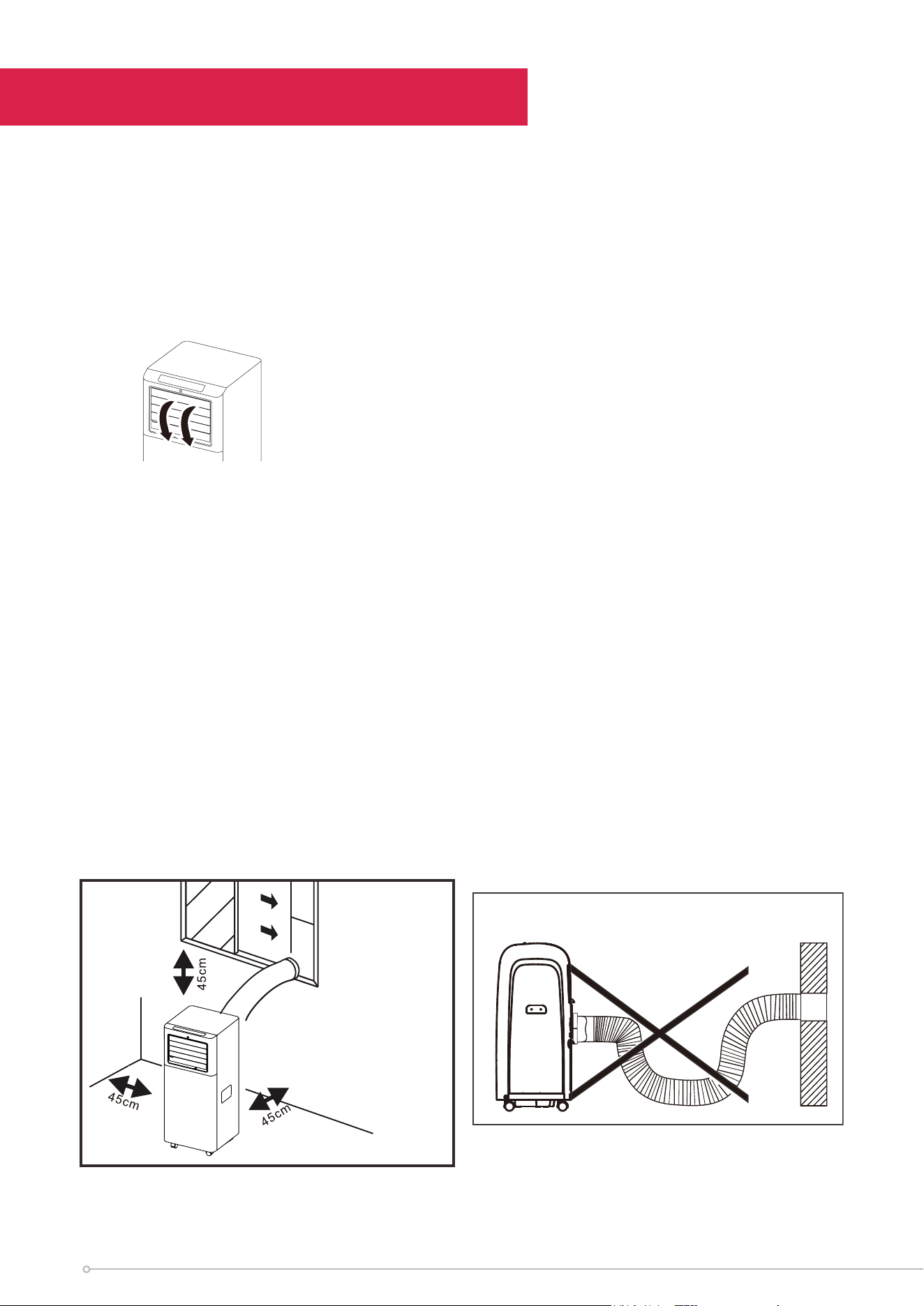
Installation
PREPARATION
NOTE: All the illustrations in the manual are for explanatory purposes only. Your
machine may be slightly dierent, but the actual shape will be similar. The unit can
be controlled by the unit control panel alone or with the remote controller.
NOTE: Open the deecter before rst time use
EXHAUST HOSE INSTALLATION
The exhaust hose and adaptor must be installed or removed in accordance with the
usage mode. For COOL mode the exhaust hose must be installed. For FAN or DRY
mode the exhaust hose must be removed.
CHOOSING THE RIGHT LOCATION
Your installation location should meet the following requirements:
• Make sure that you install your unit on an even surface to minimize noise and
vibration.
• The unit must be installed near a grounded plug, and the Collection Tray Drain
(found on the back of the unit) must be accessible.
• The unit should be located at least 50cm from the nearest wall to ensure proper
air circulation. The horizontal louver blade should be at least 50cm away from
obstacles.
• DO NOT cover the Intakes, Outlets or Remote Signal Receptor of the unit, as this
could cause damage to the unit.
14
Installation
HOW TO STAY COOL WITH A PORTABLE AIR CONDITIONER
Because of a new MEPS test procedure for Portable Air Conditioners, you may
notice that the cooling capacity claims on portable air conditioner packaging
are significantly lower than that of models produced prior to 2020. This is due to
changes in the test procedure, not to the portable air conditioners themselves.
TOOLS NEEDED
• Medium Philips screwdriver
• Tape measure or ruler
• Knife or scissors
• Saw (optional, to shorten window kit for narrow windows
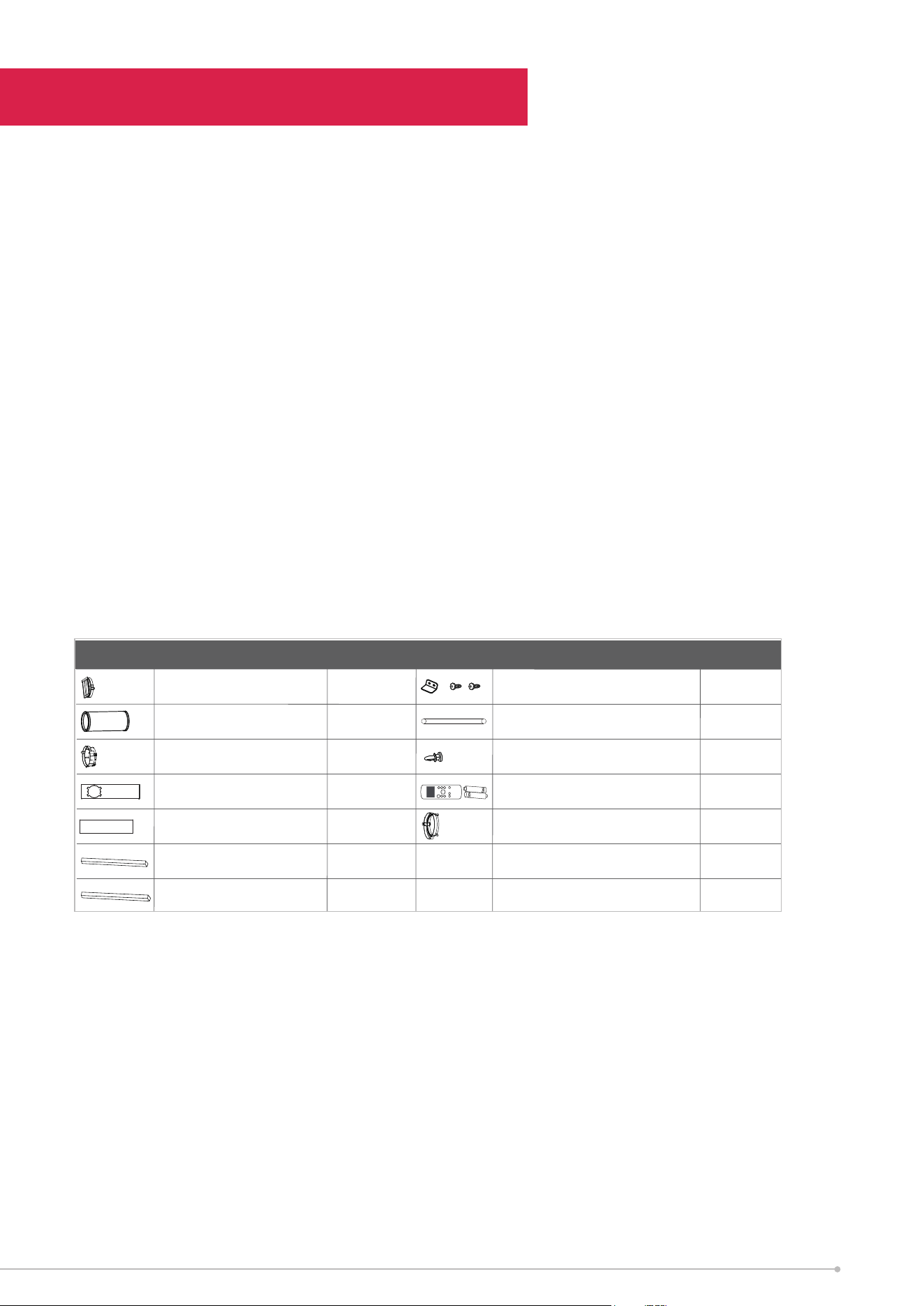
ACCESSORIES
Page 14
Window Installation Kit
Step Two: Install the Exhaust hose assembly to
the unit
Installation
Instructions
Type window installation
Type window installation
Press the exhaust hose(or extended exhaust hose)
into the window slider adaptor(or wall exhaust
adaptor) and unit adaptor, clamp automatically by
elastic buckles of the adaptors.
Step One: Preparing the Exhaust Hose assembly
Exhaust hose
Extended Exhaust
hose
Exhaust hose assembly
Unit adaptor
Window slider
adaptor
Exhaust hose
Exhaust hose
assembly
Push the Exhaust hose into the airoutlet opening of
the unit along the arrow direction.
Other Regions
Name of Accessories
Qty.
Shape
Name of Accessories
Qty.
Shape
1 pc(*)Window Slider A
Bolt
1 pc 1 set(*)Unit Adaptor Security Bracket and 2 Screws
1 pc 1 pcExhaust Hose Drain Hose
1 pc(*)Window Slider Adaptor
ON /O FF
TEMP
SHORT
CUT
TIM E R
ON
TIM E R
OFF
MODE
FAN
SLEEP
SW IN G
LED
1 set(*)
1 pc(*)Window Slider B
Remote Controller and Battery
2 pc(*)Foam Seal A (Adhesive)
1 pc(*)Foam Seal C (Non-adhesive)
1 pc(*)
1 pc(*)
Exhuast Hose Adaptor
NOTE: To ensure proper function, DO NOT overextend or bend the hose. Make sure
that there is no obstacle round the air outlet of the exhaust hose (in the range of
500mm) in order to the exhaust system works properly. All the illustrations in this
manual are for explanatory purposes only. Your air conditioner may be slightly
dierent, the actual shape will be similar.
15
Installation
WINDOW INSTALLATION KIT
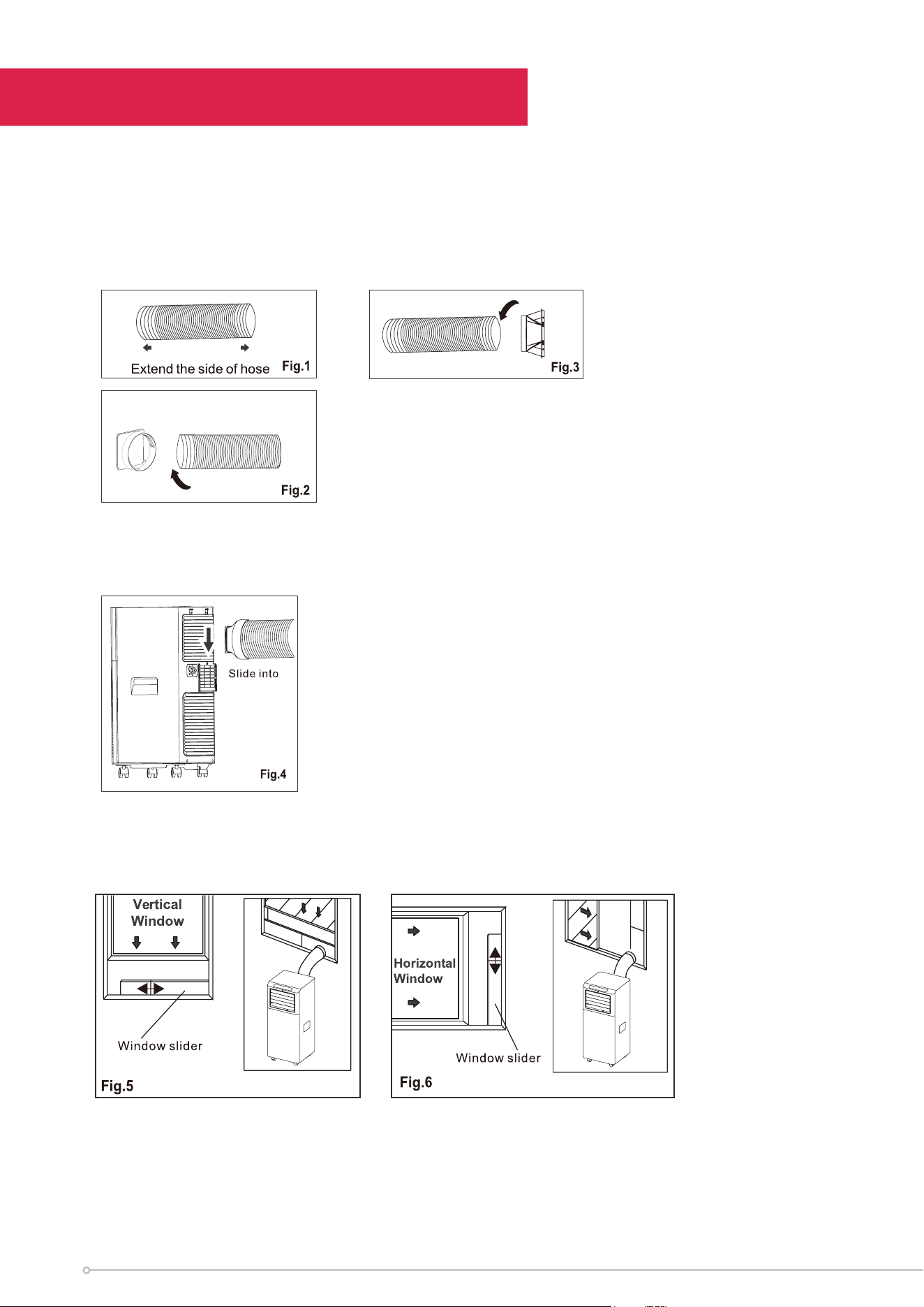
Preparing the Exhaust Hose assembly
• Extend either side of the hose (Fig. 1) and screw in the inlet (Fig. 2)
• Extend the other side of the hose and screw it to the hose outlet (Fig. 3)
Install the Exhaust hose assembly to the unit
• Install the hose inlet into the unit (Fig. 4)
• Afx the hose outlet into the window slider kit and seal (Fig. 5 & 6)
16
Installation
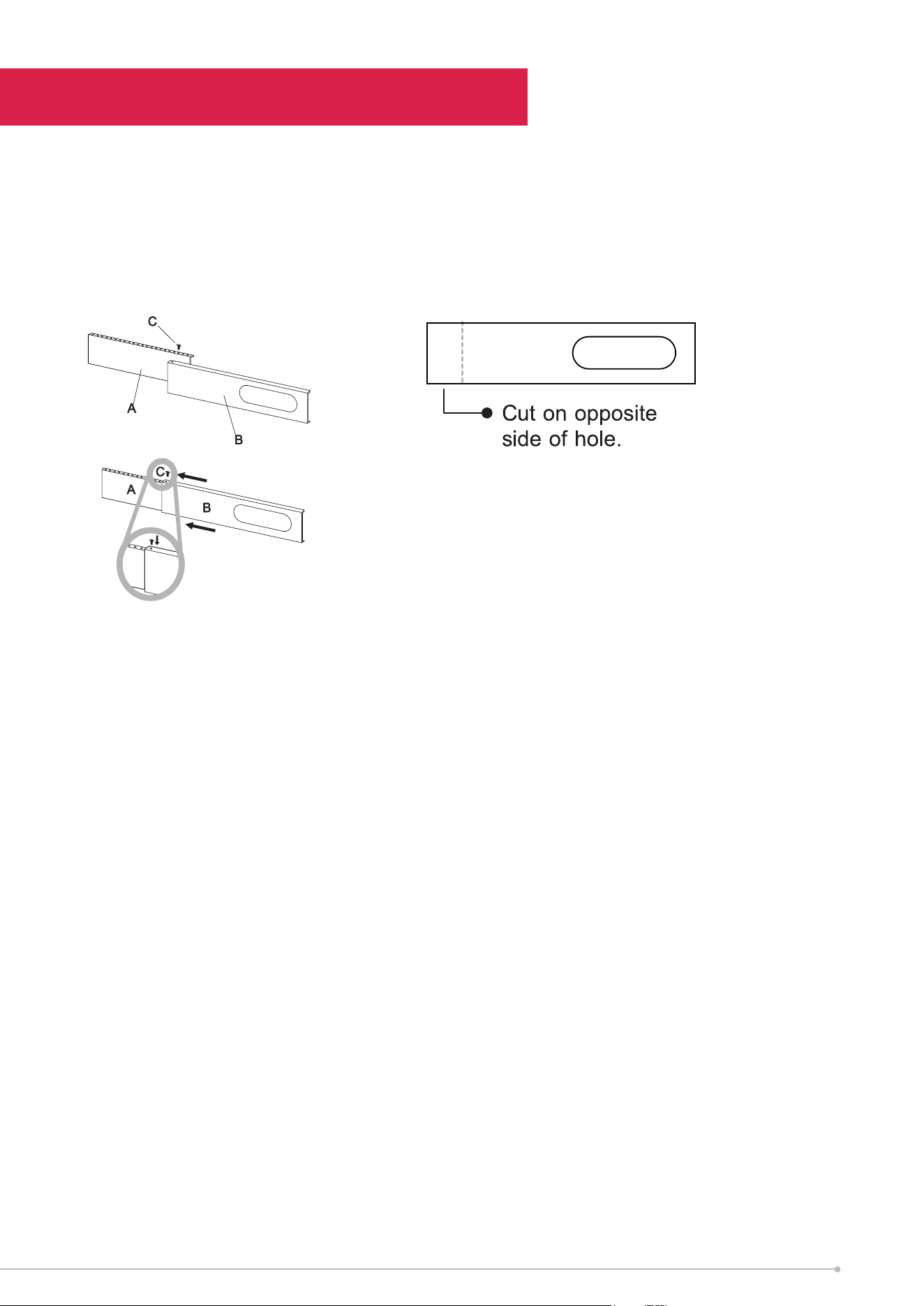
Preparing the Adjustable Window Slider
• Depending on the size of your window, adjust the size of the window slider and
(optionally) secure it with screws.
• If the length of the window is less than the minimum length of the window kit,
cut the end without the opeing short enough to fit.
NOTE: Once the Exhaust Hose assembly and Adjustable Window Slider are
prepared, choose from one of the following two installation methods.
Type 1: Hung Window or Sliding Window Installation (For some models).
17

Functions
ON/OFF
Press to turn the unit on/o.
MODE
Press the MODE button to select the appropriate operating MODE. The modes that
can be selected, follow this sequence COOL > FAN and DRY. The selected mode
indicator light will illuminate on the control panel.
FAN MODE
Press the MODE button until the FAN indicator light comes on. Press the FAN
SPEED button on the remote controller to choose the fan speed. The temperature
can not be adjusted in this mode, only the fan speed. The exhaust hose needs to be
removed during FAN MODE operation.
Up (-) / Down (+)
The Up (+) and Down (-) buttons are used to adjust (increase/decrease) the
temperature settings in 1°C increments. The temperature range can be set from 17°C
to 30°C.
NOTE: The control panel is capable of displaying the temperature in either degrees
Fahrenheit or degrees Celsius. To convert from one to the other, press and hold the
Up and Down buttons at the same time for 3 seconds.
COOL MODE
Press the MODE button until the COOL indicator light comes on. Press the Up (+)
or Down (-) buttons to select the desired room temperature. Press the FAN SPEED
button to adjust the fan speed. The exhaust hose needs to be used during COOL
MODE operation.
DRY / DEHUMIDIFY
Press the MODE button until the DRY ( ) indicator light comes on. The fan
speed or temperature cannot be set during DRY MODE. The fan will automatically
operate at LOW speed. NOTE: Keep windows and doors closed. The exhaust hose
needs to be attached during DRY MODE operation.
SETTING THE TIMER
-This timer can be used to delay the appliance startup or shutdown, this avoids
wasting
electricity by optimising operating periods.
18
Functions
PROGRAMMING START UP
1. Turn on the appliance, choose the desired mode (e.g. COOL, 24°C, high fan
speed). Turn o the appliance.
2. Press the TIMER button, the Timer symbol and number of hours will flash.
3. Press the UP/DOWN buttons until the desired time is displayed.
4. Wait 5 seconds. The timer will be active and the TIMER symbol will light up.
5. Press the TIMER button or the ON/OFF button to cancel the timer. and the
TIMER symbol will dissapear.
PROGRAMMING SHUT DOWN
1. When the appliance is running, press the TIMER button. The TIMER symbol and
the number of hours will flash.
2. Press the UP/DOWN buttons until the desired time is displayed.
3. Wait 5 seconds. The timer will be active, the TIMER symbol will light up.
4. Press the TIMER button or the ON/OFF button to cancel the timer. and the
TIMER symbol will dissapear.
TIPS FOR OPTIMAL USE
To get the best from your appliance, follow these recommendations:
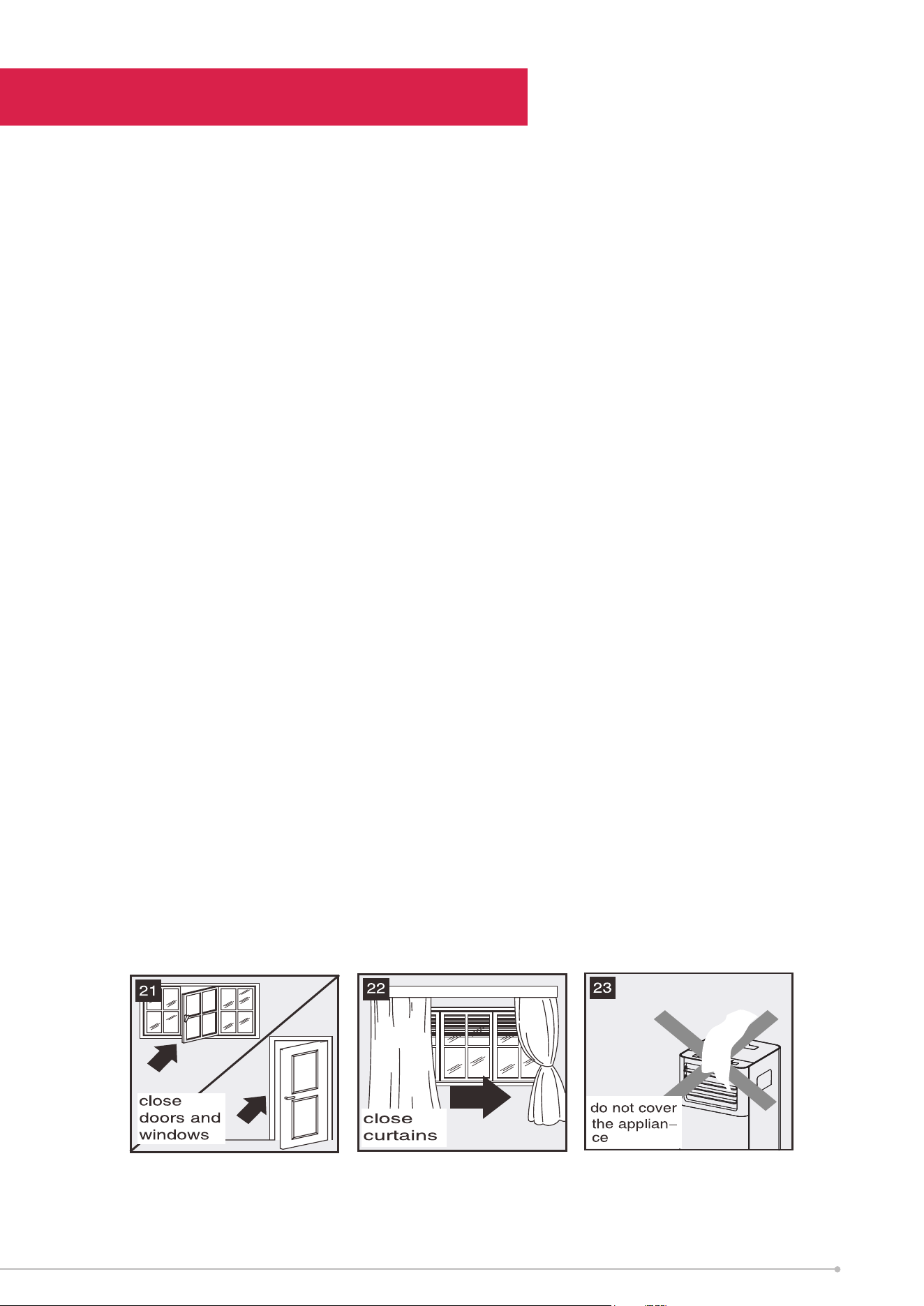
• Close the windows and doors in the room to be air conditioned (fig. 21). When
installing the appliance semi-permanently, a door should be left slightly open (as
little as 1 cm) to guarantee optimal ventilation.
• Protect the room from direct exposure to the sun by partially closing curtains
and/or blinds to make the appliance much more economical to run (fig. 22).
• Never rest objects of any kind on the appliance.
• Do not block the air inlet or outlet of the appliance. Reduced air flow will result in
poor performance and could damage the unit (fig. 23).
• Make sure there are no heat sources in the room; Never use the appliance in very
damp rooms (laundries for example).
• Never use the appliance outdoors.
• Ensure the appliance is standing on a level surface. If necessary, place the castor
locks under the front wheels.
19

Functions
LED DISPLAY
The LED display shows the set temperature while on COOL or AUTO MODE. While
in DRY and FAN MODE, it shows the ambient room temperature.
ERROR CODES
- PROBE FAILURE (sensor damaged): if this is displayed, please contact your
local authorised service centre
- FULL TANK (water tank is full): Empty the internal water tank, following the
instructions in the Functions section.
Protection code:
P1 - Bottom tray is full - Connect the drain hose and drain the collected water
away. If protection repeats, call for techinical assistance.
NOTE: When one of the above malfunctions occurs, turn the unit OFF, and check
for any obstructions. Restart the unit, if the malfunction is still present, turn OFF the
unit and unplug the power cord. Contact the manufacturer or its service agents or a
similar qualified person for service.
SLEEP/ECO MODE
This feature can only be activated by the remote control. To activate SLEEP mode,
press the SLEEP button on the remote control. The set temperature will increase
(cooling) after 60 minutes. The set temperature will increase again by another
1°C after an additional 60 minutes. This new temperature will be maintained for 6
hours. This ends the Sleep mode and the unit will automatically shut o. The SLEEP
function can be cancelled at any time during operation by pressing the SLEEP,
MODE or FAN SPEED button.
NOTE: SLEEP model cannot be used under FAN or DRY mode.
AUTO-RESTART
If the unit turns o unexpectedly due to a power cut, it will automatically restart in
the previous settings when the power resumes.
20
Functions
WAIT 3 MINUTES BEFORE RESUMING OPERATION
After the unit has been turned o, it can not be restarted in the first 3 minutes.
This is to protect the unit & compressor. Operation will automatically start after 3
minutes.
AIR FLOW DIRECTION ADJUSTMENT
The vertical louvres need to be adjusted manually. Always ensure the unit is OFF
when making manual adjustments.
• Angle the louvres in the direction required
• Do not place any heavy objects on or block the louvres, doing so will cause
damage to the unit.
• Ensure the louvre is always fully opened during operation.
POWER MANAGEMENT
Under cooling operation, when the ambient temperature is lower than the set
temperature for a period of time, the unit will be automatically operate the power
management feature. The compressor and fan motor will stop. When the ambient
temperature is higher than the set temperature, the unit will automatically quit
power management mode and the compressor and/or fan motor will run.
WATER DRAINAGE
When there is excess water condensation inside the unit, the appliance will cease
function and siplay the Full Tank icon ( ). This indicates that the water tank needs
to be drained using the following procedure.
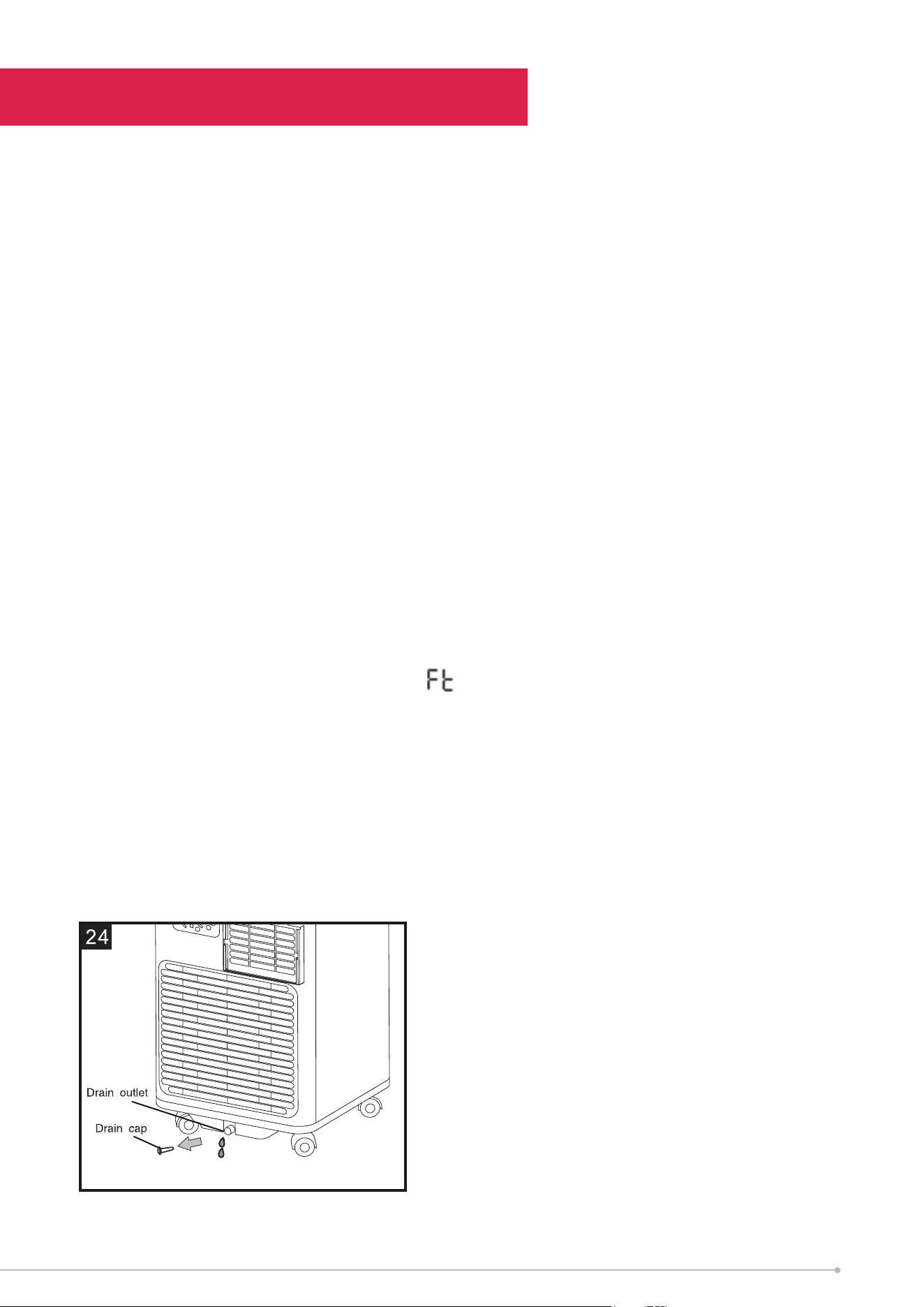
MANUAL DRAINING (Fig 24)
1. Unplug the unit from power source.
2. Place a pan (not the unit's tank) under the lower drain plug. See diagram.
3. Remove the lower drain plug.
4. Water will drain out and collect in the pan.
5. After the water is drained, replace the lower drain plug firmly.
6. Turn the unit on
21
Remote Control
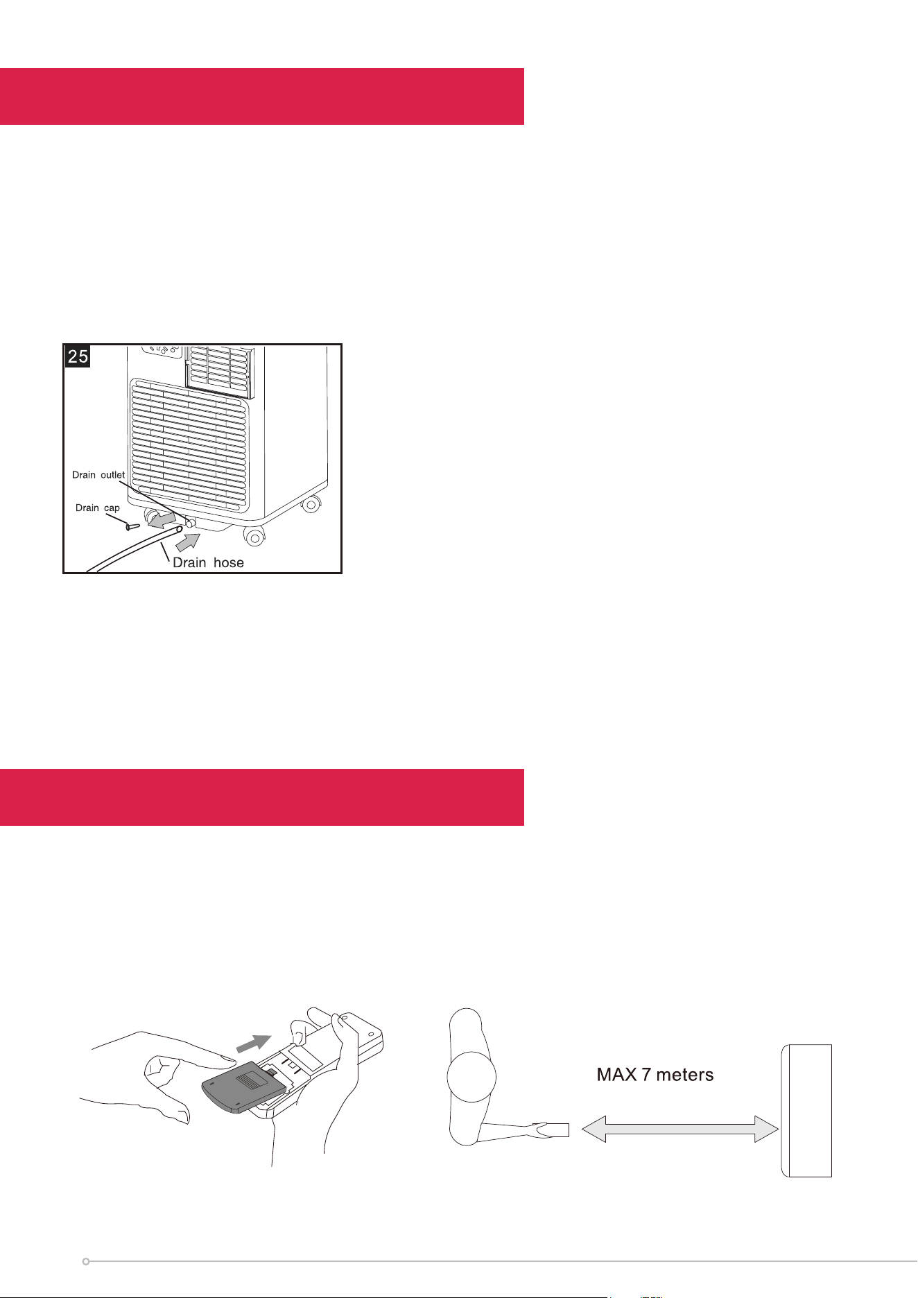
NOTE: Make sure the hose is secure so there are no leaks. Direct the hose toward the
drain, making sure that there are no kinks that will stop the warter flowing. Place the
end of the hose into the drain and make sure the end of the hose is down to let the
water flow smoothly. When the continuous drain hose is not used, ensure that the
drain plug and knob are installed firmly to prevent leakage.
Using the Remote Control
1. Open the battery cover of the remote control, and insert 2 x AAA batteries.
2. Please point to the receiver and be within 8m when using the remote control.
3. If the battery voltage is low, please open the battery cover as per the diagram
and replace with new batteries (2 x AAA). Then replace the battery cover.
Functions
CONTINUOUS DRAINING (Fig 25)
While using the unit in dry mode, continuous drainage is recommended.
1. Unplug the unit from the power source.
2. Remove the drain plug. While doing this operation some residual water may spill,
a pan is recommened to collect the water.
3. Connect a drain hose (12.7mm or 1/2"). See diagram.
4. The water can be continuously drained through the hose.
5. Turn the unit on
22
Cleaning
SAFETY PRECAUTIONS
• Always unplug the unit before cleaning or servicing.
• DO NOT use flammable liquids or chemicals to clean the unit.
• DO NOT wash the unit under running water. Doing so causes electrical danger.
• DO NOT operate the machine if the power supply was damaged during
cleaning. A damaged power cord must be replaced with a new cord from the
manufacturer.
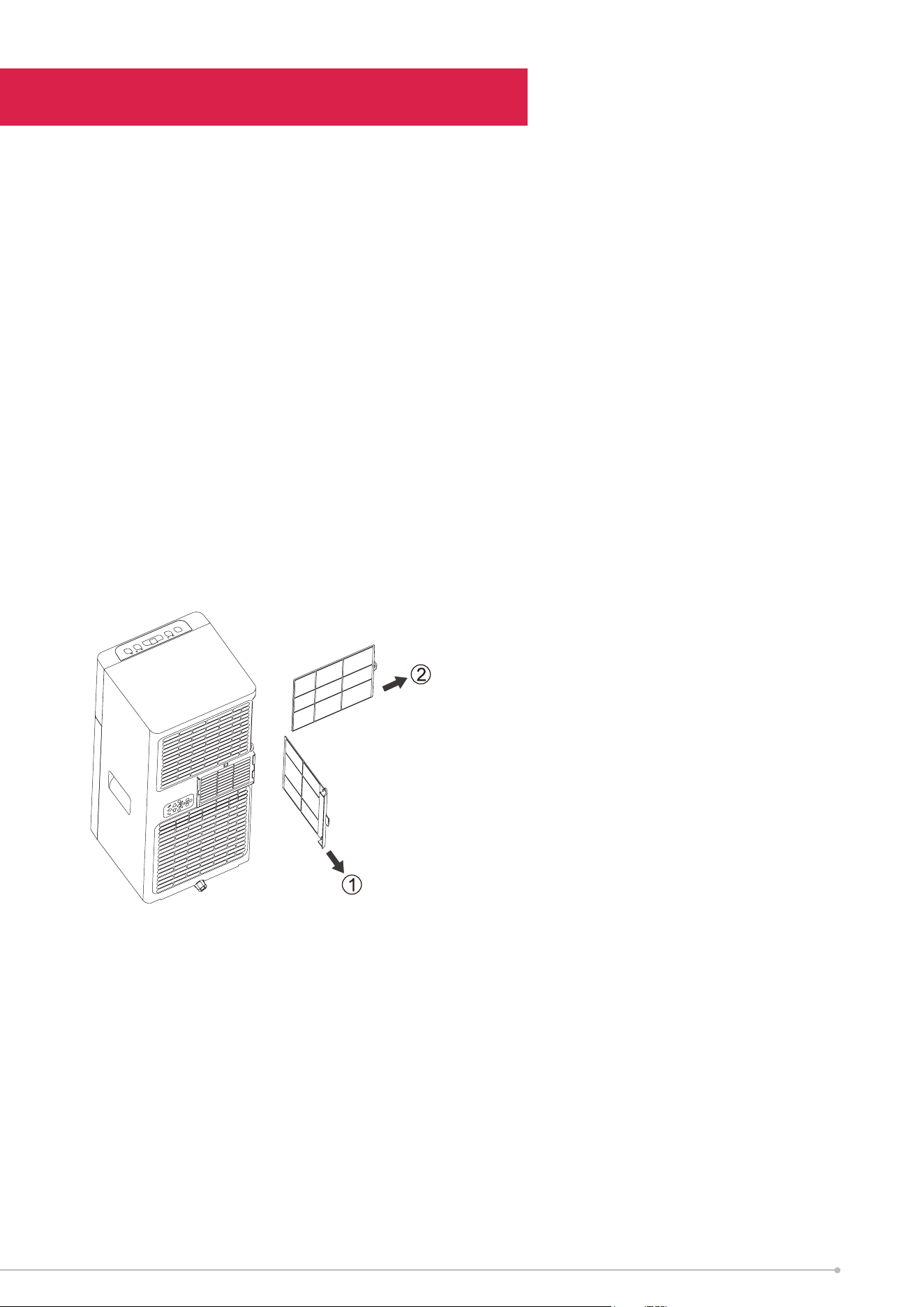
AIR FILTER
CAUTION: DO NOT operate the unit without filter because dirt and lint will clog it
and reduce performance.
• Be sure to clean the air filter every 2 weeks for optimal performance.
• The water collection tray should be drained immediately after P1 error occurs,
and before storage to prevent mould.
• In households with animals, you will have to periodically wipe down the grill to
prevent blocked airflow due to animal hair.
OUTSIDE CABINET
1. Remove any dust build up with a soft brush.
2. Wipe the surface of the unit with a soft damp cloth. Mild detergent can be used
for any stubborn marks.
DO NOT use abrasive sponges, scouring pads, or a sti brush to clean the unit.
IMPORTANT
The control panel and other parts must not come into contact with water or any
other liquids.
23

Storage
If not using the unit for an extended period of time. After cleaning please:
• Turn the unit o, unplug and take care of the mains lead & plug.
• Drain the unit’s water collection tray according to the instructions in the following
section.
• Run the appliance on FAN mode for 12 hours in a warm room to dry it and prevent
mould.
• Clean the air filter as described in the previous section.
• Remove batteries from the remote control
•
Cover the unit and store it upright in a location where it will not receive direct sunlight.
NB- Prolonged exposure to direct sunlight will discolour the enclosure.
If the unit fails to operate eciently, is broken or other problems arise, unplug and
do not operate. Ask for advice by calling your local after sales service agent or the
Customer Care Centre on 1300 556 816 (AU) / 0800 666 2824 (NZ).
Maintenance
24

Recycling: Do not dispose of electrical appliances as unsorted
municipal waste. Use separate collection facilities. Contact your
local government for information regarding the collection systems
available. If electrical appliances are disposed of in landlls or dumps,
hazardous substances can leak into the ground water, polluting the
food chain and damaging health and well-being.
Warranty
Please refer to the warranty card in the box for warranty information. For any
troubleshooting advice, please contact the relative Customer Care Centre below.
Glen Dimplex Australia Pty Ltd Glen Dimplex New Zealand Ltd
8 Lakeview Drive, 38 Harris Road, East Tamaki,
Scoresby 3179, Victoria Auckland 2013
Australia New Zealand
Ph: 1300 556 816 Ph: 0800 666 2824
25

Customer Care: 1300 556 816
customer.care@glendimplex.com.au
www.dimplex.com.au
Supplied by Glen Dimplex Australia
8 Lakeview Drive, Scoresby, Victoria, 3179
© Glen Dimplex Australia. All rights reserved. Material contained in this publication may not be reproduced in whole or in part, without
prior permission in writing of Glen Dimplex Australia.
DCP9C v1
26