16574
STOP!
STOP!
Call Us First!
DO NOT RETURN TO STORE.
For immediate help with assembly or product information
call our toll free number:
1-800-844-9273
or email:
customerservice@yardline.net
Our staff is ready to provide assistance
M-F 8:00 AM to 6:00 PM EST
Saturday 8:30 AM to 5:00 PM EST

(This page intentionally left blank.)
05/09/2016
KEEP THIS MANUAL FOR FUTURE REFERENCE
ACTUAL FLOOR SIZE IS 96 x 168" (243,8 x 426,7 cm)
OPTION 1:
DOOR LOCATION
LEFT SIDE OF FRONT WALL
OPTION 2:
DOOR LOCATION
RIGHT SIDE OF FRONT WALL
16574
BEFORE YOU BEGIN
IMPORTANT!
READ INSTRUCTIONS THOROUGHLY PRIOR TO BEGINNING ASSEMBLY.
• BUILDING RESTRICTIONS AND APPROVALS
Be sure to check with local building department and homeowners association for speci c restrictions and/ or requirements before building.
• ENGINEERED DRAWINGS
Contact our Customer Service Team if engineered drawings are needed to pull local permits.
• SURFACE PREPARATION
To ensure proper assembly you must build your shed on a level surface. Recommended methods and materials to level your shed are
listed on page 9.
• CHECK ALL PARTS
Inventory all parts listed on pages 3 - 7. Contact our Customer Service Team if any parts are missing or damaged.
• ADDITIONAL MATERIALS
You will need additional materials to complete your shed. See page 8 for required and optional materials and quantities.
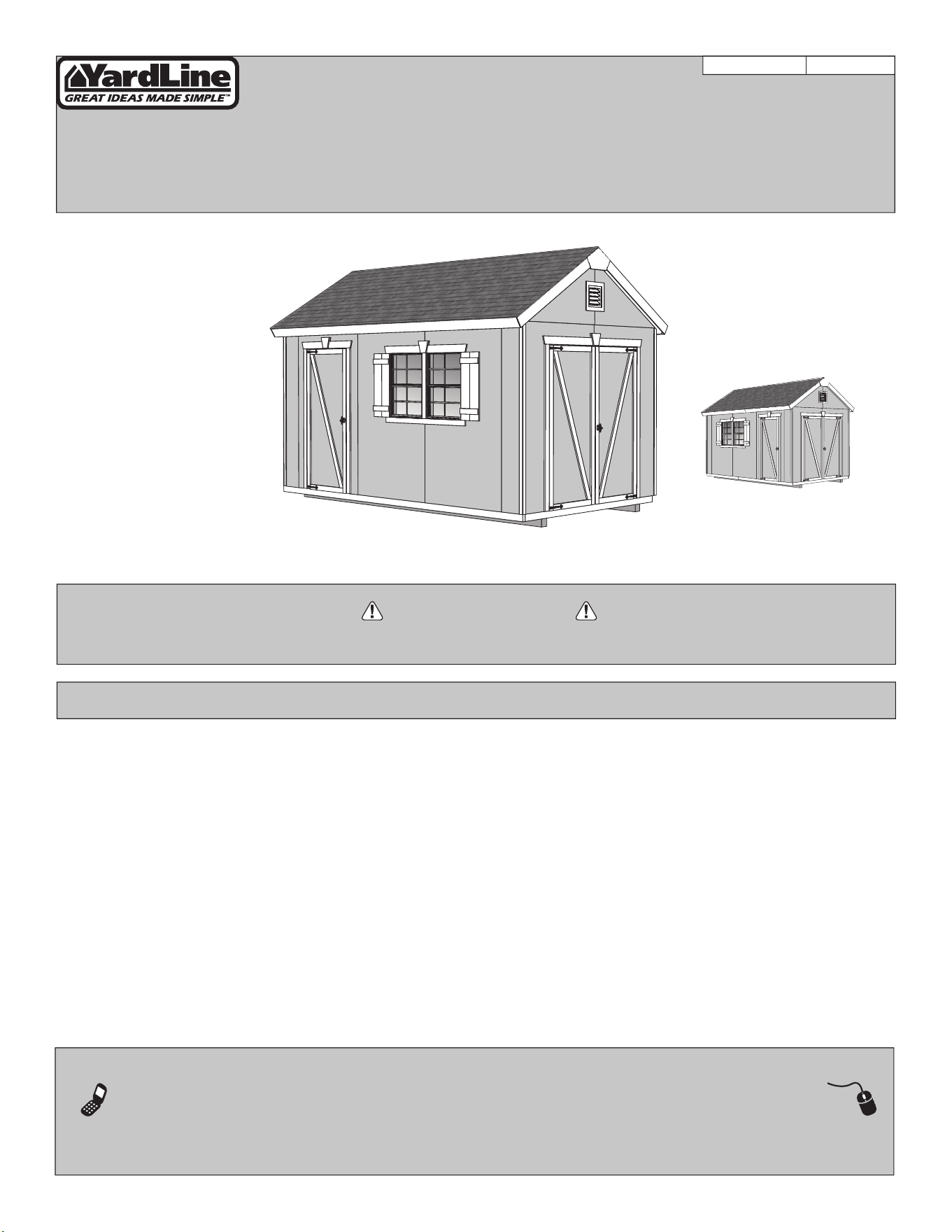
CRESTWOOD GABLE 8' x 14' (244 x 426,7 cm)
- CUSTOMER SERVICE -
Call: 1-800-844-9273 email: customerser[email protected]
A Backyard Products Company
2
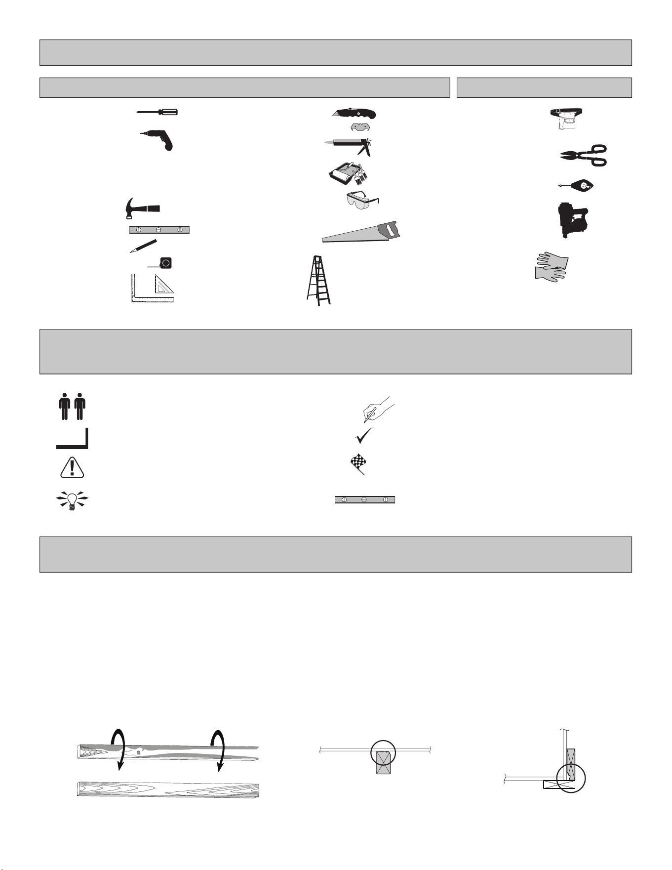
TOOLS
Safety! Always use approved safety glasses during assembly.
OptionalRequired
HELPFUL REMINDER SYMBOLS
Look for these symbols for helpful reminders throughout this manual.
ORIENT LUMBER AND TRIM FOR BEST APPEARANCE
= Assistance Required; two or more people.
= Ensure squareness.
= Important required step or operation.
= Helpful assembly hint.
= Mark part with pencil.
= Beginning of steps for assembly or installation.
= You have nished the assembly or installation.
= Level
❑ Gloves
Framing lumber is graded for structural strength and not appearance. Exterior trim is graded for one good side.
Always install the material leaving the best edge and best surface visible. Please remember that these blemishes in no way
negatively affect the strength or integrity of our product. (See Fig. A, B, C.)
A
❑ Safety Glasses
❑ Tape Measure
❑ Paint Tools
❑ Ladder
❑ Caulk Gun
❑ Hammer
❑ Level
FINISH
BEGIN
❑ Pencil
❑ Phillips
Screwdriver
❑ Tool Belt/
Nail Pouch
❑ Chalk Line
❑ Nail Gun
• gun nails
❑ Tin Snips
(for drip edge)
❑ Square
or
❑ Utility Knife
❑ Shingle Blades
B C
❑ Drill / Driver
❑ 1/8" Drill Bit
❑ #2 Philips Drive Bit
❑ 1/4" Drill Bit
❑ 5/16" Drill Bit
❑ 1/2" Drill Bit
❑ Hand Saw
WOOD SIZE CONVERSION CHART
Nominal Board Size Actual Size
1" x 4".................3/4" x 3-1/2" (1,9 x 8,9 cm)
2" x 4"..............1-1/2" x 3-1/2" (3,8 x 8,9 cm)
2" x 3"..............1-1/2" x 2-1/2" (3,8 x 6,3 cm)
1" x 3".................3/4" x 2-1/2" (3,8 x 6,3 cm)
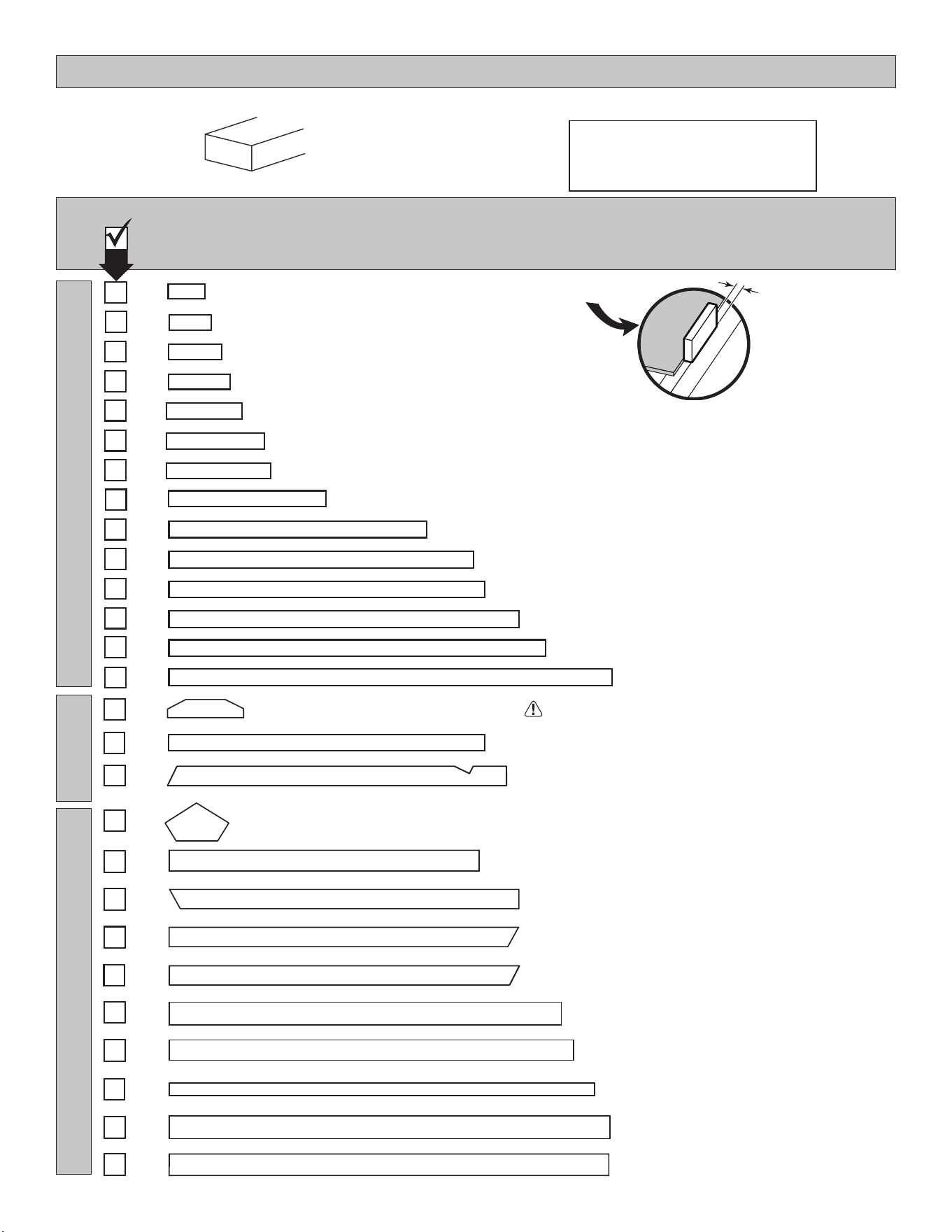
PARTS IDENTIFICATION AND SIZES
RS
RS
Part identication
letters are stamped on some parts.
Check these locations for
part stamp.
WALLS
x3
2 x 4 x 89" (5,1 x 10,2 x 226,1 cm)
SZ
x24
2 x 4 x 80" (5,1 x 10,2 x 203,2 cm)
TK
x2
2 x 4 x 68-1/2" (5,1 x 10,2 x 174 cm)
YFA
x3
2 x 4 x 72" (5,1 x 10,2 x 182,9 cm)
TM
x1
2 x 4 x 64" (5,1 x 10,2 x 162,6 cm)
UX
PARTS LIST
INVENTORY YOUR PARTS before you begin.
We suggest sorting parts by the category they are listed in.
RAFTERS
TRIM
x5
2 x 4 x 10" (5,1 x 10,2 x 25,4 cm)
PWA
x4
2 x 4 x 8-1/2" (5,1 x 10,2 x 21,6 cm)
CPA
x2
2 x 4 x 6" (5,1 x 10,2 x 15,2 cm)
PVA
x8
3/8 x 1-3/4 x 81-1/2" (1 x 4,4 x 207 cm)
x4
2 x 4 x 96" (5,1 x 10,2 x 243,8 cm)
TP
1 x 3 x 5" (2,5 x 7,6 x 12,7 cm) Gauge Block for 3/4" (1,9 cm) measurement
x1
GAA
3/4"
(1,9 cm)
3
x16
2 x 4 x 63-7/8" (5,1 x 10,2 x 162,2 cm)
ASA
1 x 4 x 60" (1,6 x 10,2 x 152,4 cm)
x2
JF
x2
3/8 x 4-7/8 x 73-1/2" (1 x 12,4 x 186,7 cm)
x2
3/8 x 4-3/4 x 77-1/4" (1 x 12,1 x 196,2 cm)
x2
3/8 x 4-7/8 x 96" (1 x 12,4 x 243,8 cm)
x2
3/8 x 4-3/4 x 64-1/8" (1 x 12,1 x 162,9 cm)
x2
3/8 x 4-3/4 x 64-1/8" (1 x 12,1 x 162,9 cm)
x4
3/8 x 4-3/4 x 54-5/8" (1 x 12,1 x 138,7 cm)
x2
3/8 x 4-3/4 x 96" (1 x 12,1 x 243,8 cm)
x4
2 x 4 x 64-1/8" (5,1 x 10,2 x 162,9 cm)
ATA
x2
2 x 4 x 20" (5,1 x 10,2 x 50,8 cm)
ABA
x6
2 x 4 x 22-1/2" (5,1 x 10,2 x 57,1 cm)
AO
x2
2 x 4 x 12-1/2" (5,1 x 10,2 x 31,8 cm)
AJ
x2
2 x 4 x 35" (5,1 x 10,2 x 88,9 cm)
QT
x2
3/8 x 10 x 17" (1 x 25,4 x 43,2 cm)
x14
6 x 24" (15,2 x 61 cm) OSB OR WOOD GRAIN
WINDOW TRIM, DOOR TRIM & SHUTTERS
4
NOTE: Panel parts are not stamped.
LOFT & SHELVES
x1
19/32 x 2-1/2 x 30-1/8" (1,5 x 6,3 x 76,5 cm)
AZ
OOx3
1-1/4 x 2-1/2 x 69" (3,2 x 6,3 x 175,3 cm)
AUA
x1
19/32 x 2-1/2 x 53" (1,5 x 6,3 x 134,6 cm)
DEAx1
19/32 x 3-1/2 x 55" (1,5 x 8,9 x 139,7 cm)
LRA
x2
1 x 4 x 69-3/4" (2,5 x 10,2 x 177,2 cm)
ZJ
x1
19/32 x 2-1/2 x 72" (3,2 x 6,3 x 182,9 cm)
x4
19/32 x 2-1/2 x 11" (1,5 x 6,3 x 27,9 cm)
DJA
x4
19/32 x 5-1/2 x 30-1/8" (1,5 x 14 x 76,5 cm)
DHA
x1
19/32 x 2-1/2 x 70-7/8" (1,5 x 6,3 x 180 cm)
DGR
x2
19/32 x 2-1/2 x 70-7/8" (1,5 x 6,3 x 180 cm)
DGL
x1 DFA
19/32 x 3-1/2 x 72" (1,5 x 8,9 x 182,9 cm)
x1 DDA
19/32 x 3-1/2 x 40" (1,5 x 8,9 x 101,6 cm)
x1
2 x 4 x 96" (5,1 x 10,2 x 243,8 cm)
TP
x5
2 x 3 x 96" (5,1 x 7,6 x 243,8 cm)
PT
x2
7/16 x 10-1/2 x 89" (1,1 x 26,7 x 226,1 cm)
x1
7/16 x 26-5/8 x 89" (1,1 x 67,6 x 226,1 cm)
x2
2 x 3 x 21-3/4" (5,1 x 7,6 x 55,2 cm)
AED
x3
19/32 x 6-7/16 x 5-1/2" (1,5 x 16,4 x 14 cm)
NRA
x3
19/32 x 6-7/16 x 2" (1,5 x 16,4 x 5,1 cm)
JTA
5
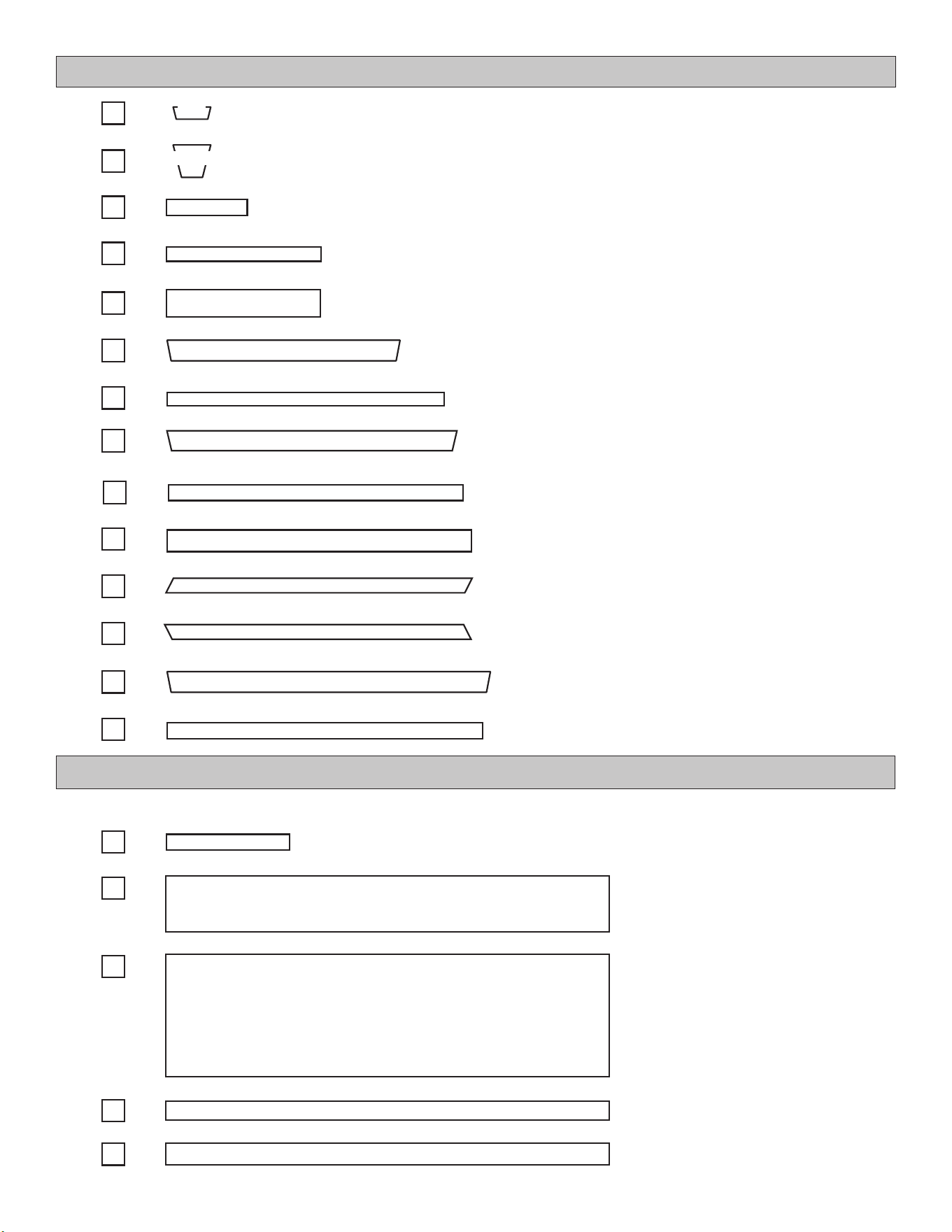
NOTE: Panel parts are not stamped.
WALL PANELS & DOORS
x5
3/8 x 48 x 84"
(1 x 121,9 x 213,4 cm)
x2
x2
x1
3/8 x 48 x 84"
(1 x 121,9 x 213,4 cm)
x1
3/8 x 48 x 84"
(1 x 121,9 x 213,4 cm)
x1
3/8 x 48 x 84"
(1 x 121,9 x 213,4 cm)
x1
3/8 x 48 x 84"
(1 x 121,9 x 213,4 cm)
x1
3/8 x 48 x 84"
(1 x 121,9 x 213,4 cm)
x1
UNIVERSAL DOOR
Right / Left
Painted
Black
on Ends
x1
LEFT DOOR
x1
RIGHT DOOR
Painted
Green on End
Painted
Red on End
x1
3/8 x 23-7/8 x 84"
(1 x 60,6 x 213,4 cm)
x2
3/8 x 11-7/8 x 84"
(1 x 30,2 x 213,4 cm)
6
ROOF PANELS
NOTE: Panel parts are not stamped.Roof panels are 7/16" (1,1 cm) thick.
7/16 x 15-7/8 x 23-7/8"
(1,1 x 40,3 x 60,6 cm)
x2
7/16 x 15-7/8 x 96"
(1,1 x 40,3 x 243,8 cm)
x2
7/16 x 15-7/8 x 48"
(1,1 x 40,3 x 121,9 cm)
x2
7/16 x 48 x 96"
(1,1 x 121,9 x 243,8 cm)
x2
7/16 x 48 x 71-7/8"
(1,1 x 121,9 x 182,6 cm)
x2
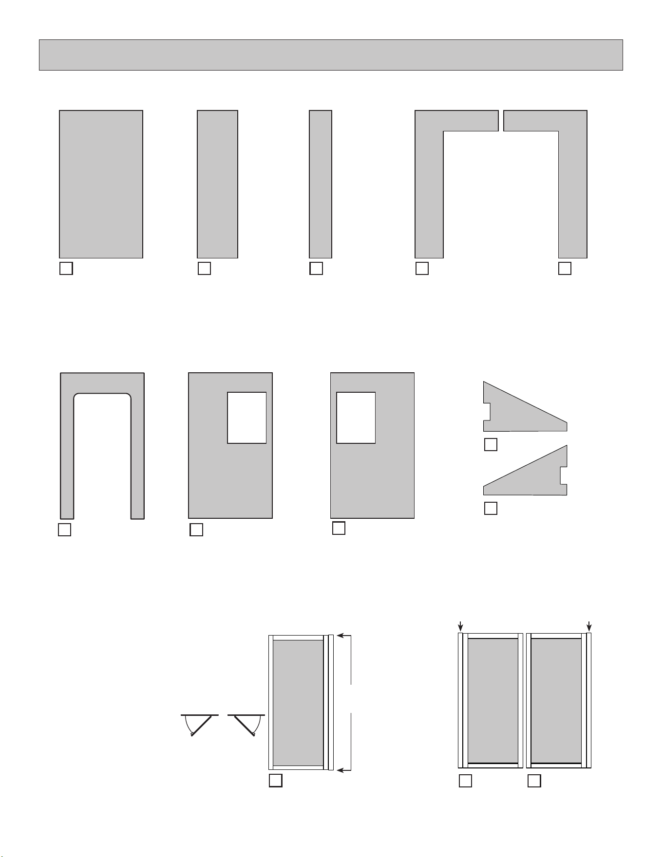
FLOOR PARTS
NOTE: Panel parts are not stamped.Floor panels are 5/8" (1,6 cm) thick.
5/8 x 23-7/8 x 96"
(1,5 x 60,6 x 243,8 cm)
x1
5/8 x 48 x 96"
(1,5 x 121,9 x 243,8 cm)
x3
x2
2 x 4 x 72" (5,1 x 10,2 x 182,9 cm)
x12
2 x 4 x 93" (5,1 x 10,2 x 236,2 cm)
x2
2 x 4 x 96" (5,1 x 10,2 x 243,8 cm)
Look for
Stamp
TREATED
x335
x130
x30
x100
x113
x27
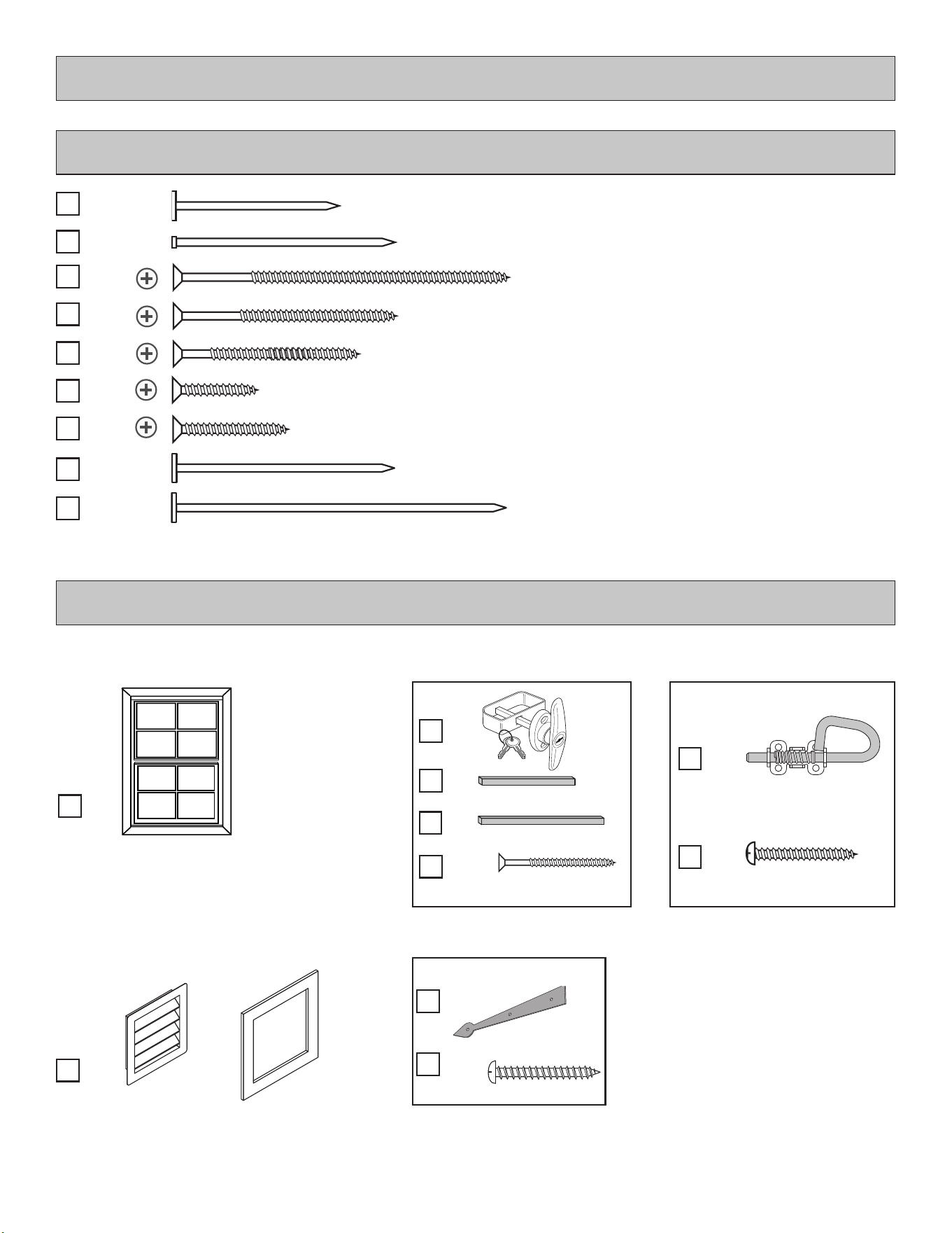
VENT/ DOOR HARDWARE/ WINDOWS
FASTENERS & HARDWARE
FASTENER/HARDWARE BAG
x7
x4
7
1-5/8" (4,1 cm)
2" (5,1 cm)
3" (7,6 cm)
3/4" (1,9 cm)
2" (5,0 cm)
1-1/2" (3,8 cm)
1" (2,5 cm)
x25
x2
3" (7,6 cm)
2" (5,1 cm)
Window
22-1/4 x 29-3/4"
(56,5 x 75,6 cm)
x2
Vent with Frame
x18
1" (2,5 cm)
x6
Decorative Hinges
Spring Bolt
x2
1" (2,5 cm)
x8
(4 screws in each package)
Boxes
Boxes
x2
x1
T-Handle
x4
1-1/2" (3,8 cm)
(2 screws in each package)
4-1/2" Shaft
x1
5-1/2" Shaft
8
DRIP EDGE ..................... 60 Feet #15 ROOFING FELT
To cover 160 Sq. Ft. of roof area.
1" GALVANIZED ROOFING NAILS.........1/4 Lb
For roong felt.
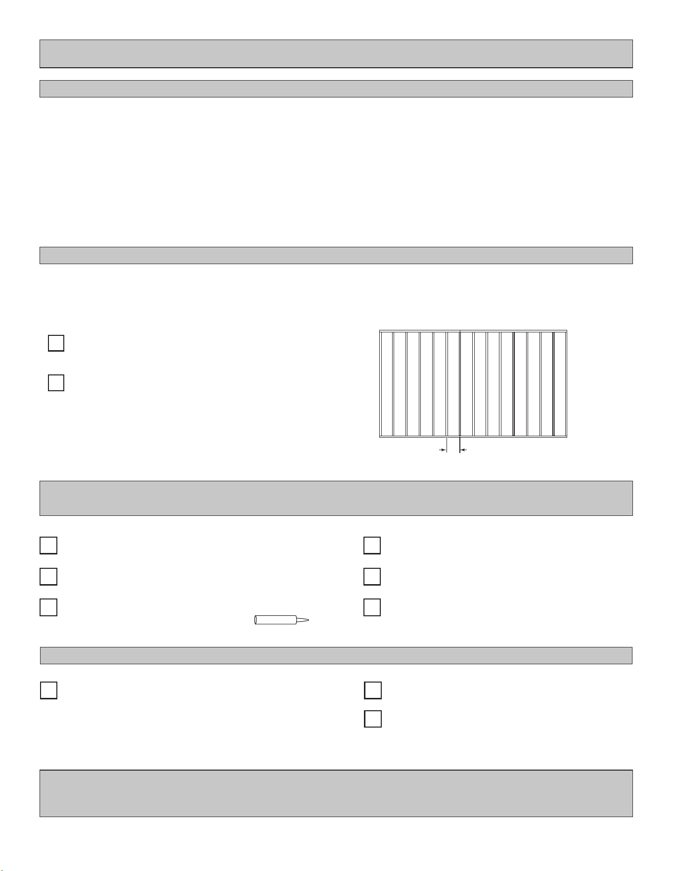
IMPORTANT! Depending on your specic use you may want to construct a heavy duty oor frame by adding additional oor joists
(shown below as shaded). Below is a list of additional materials (not included):
x3
x12
2 x 4 x 8' (5 x 10 x 243,8 cm) Treated Lumber
Cut to (3) 2 x 4 x 93" (5 x 10 x 236,2 cm)
ea. 3" (7,6 cm) Hot Dipped Galvanized Nails
Optional 12" (30,5 cm) spacing
Standard 16" (40,7 cm) spacing
OPTIONAL MATERIALS
REFER TO THE BACK OF THIS MANUAL AND THE MANUFACTURER’S INSTRUCTIONS FOR
INSTALLATION OF SHINGLES, DRIP EDGE AND FELT.
COMPLETING YOUR SHED
You will need these additional materials:
REINFORCED WOOD FLOOR FRAME (OPTIONAL)
FOUNDATION OR FLOOR MATERIALS
ADDITIONAL MATERIALS
• This shed does not include any leveling materials.
• See the FLOOR LEVELING section on page 9 for recommended methods and suggested materials to properly level your oor,
as this will vary depending on your specic site.
• If you choose to install your kit on a concrete slab refer to page 10.
3-TAB SHINGLES ............................. 7 Bundles
PAINT FOR SIDING .......................... 3 Gallons
Use 100% acrylic latex exterior paint. (2) coats recommended.
CAULK ................................................. 2 Tubes
Use acrylic latex exterior caulk that is paintable.
1" GALVANIZED ROOFING NAILS.... 3 Lbs
For shingles.
PAINT FOR TRIM .......................... 3 Quarts
Use 100% acrylic latex exterior paint.
WOOD GLUE ....................... Exterior Rated
DOOR
9
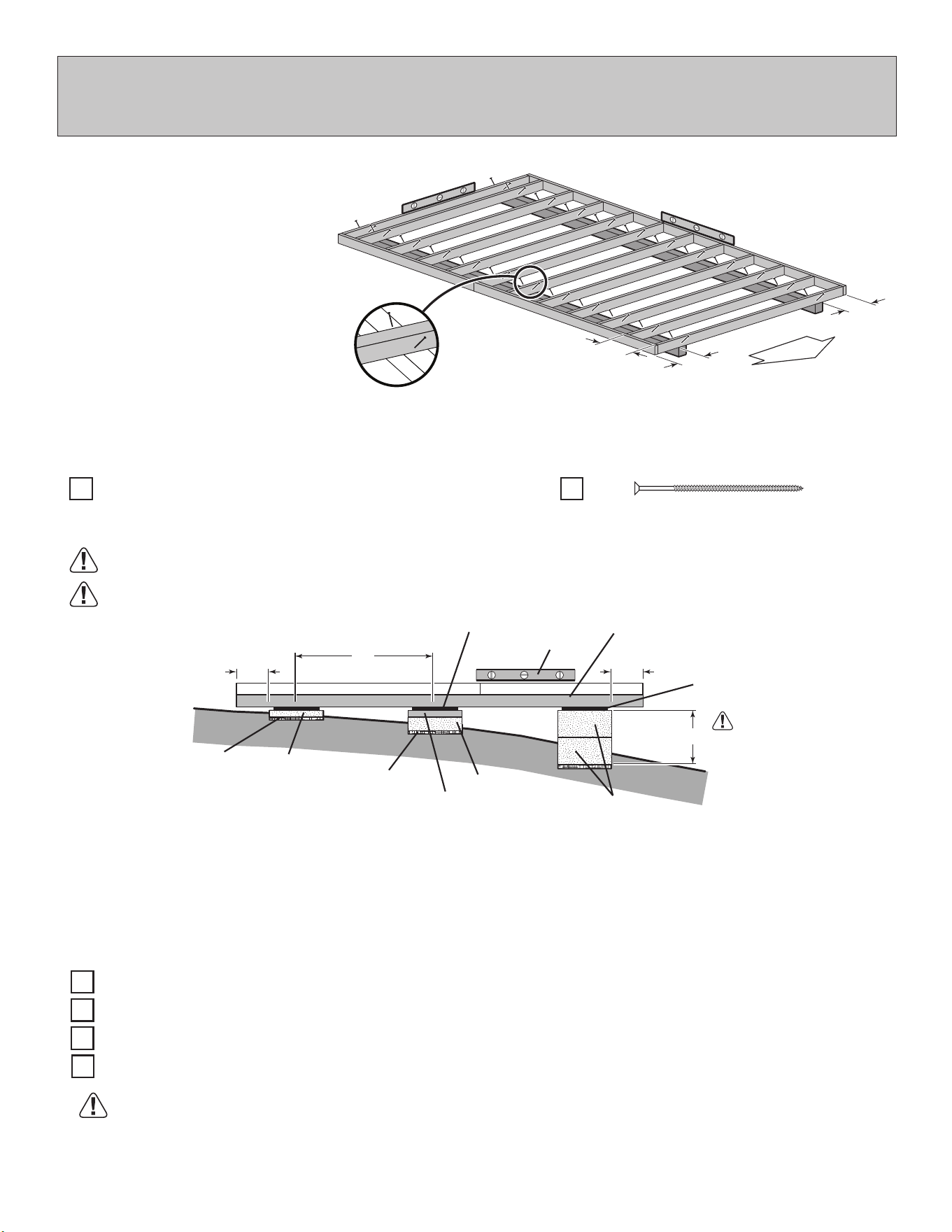
• Level under 4x4 runners only.
• Locate leveling material 12" from ends of runners and no more than 48" apart.
• Asphalt shingles should be used between 4x4 runners and blocks or treated lumber. Never use
shingles in direct contact with ground.
• For best results and aiding in water drainage use gravel under each concrete block.
LEVELING METHODS
• If you are building your shed on a concrete foundation see the following page.
CONCRETE
Use only wood treated for ground contact and fasteners approved for use with treated wood.
Always support frame seams.
Leveling higher than 16" not recommended.
LEVELING MATERIALS
Gravel
2x4 Treated Lumber
Solid Masonry Blocks in 1", 2", 4" or 8" thickness
Asphalt Shingles
8" Block
4" Block
Gravel
Gravel
Do not exceed 16".
4x4 Runner
Shingle
Shingle
Maximum between leveling
material locations.
48"
12"
2x4 Treated Lumber
2" Block
Level
12"
• 3" Screws angled into 4x4.
• (2) at each point frame
and 4x4 touch.
Runners are generally 12" (30,5 cm) from
ends of oor frame and under seams.
OPTIONAL WOOD FRAME FLOOR LEVELING OPTIONS
There are multiple ways to level your oor frame. Our recommended leveling method is shown below.
Leveling materials are not included in this kit.
PREFERRED METHOD - 4x4 TREATED RUNNERS (Typical for 8' x 14' Kit)
MATERIAL REQUIRED
4" x 4" x 14' (10,2 x 10,2 x 426,7 cm) Treated Lumber
x2
x48
3" (7,6 cm)
Fasteners for Frame to 4"x 4".
(3" Screws shown as one option.)
Minimum 3" screws / exterior grade.
12"
(30,5 cm)
16"
(40,6 cm)
12"
(30,5 cm)
Measurements to
centers of 4x4's.
10
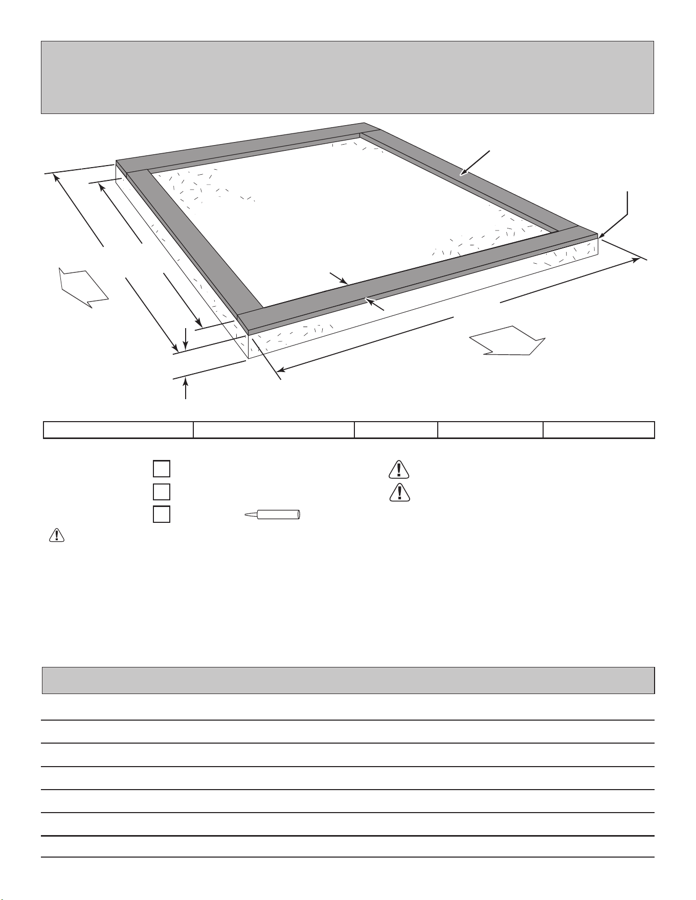
CONCRETE FOUNDATION
Your kit contains all materials to construct a wooden oor. If you choose to install your kit
on a concrete slab refer to the diagram below.
• A treated 2 x 4" (5,1 x 10,2 cm) sill plate is required when installing your shed on concrete.
Hint: Purchase full length treated lumber.
• Use a high quality exterior grade caulk beneath all sill plates.
• Fasten 2 x 4" (5,1 x 10,2 cm) sill plates to slab using approved concrete anchors (fasteners not included).
• Check local code for concrete foundation requirements.
NOTES
Allow new concrete slabs to cure for at least seven (7) days.
2" x 4" x 8' (5,1 x 10,2 x 244 cm)
Caulk
Requires:
x2
x2
x1
MUST be treated lumber.
MUST be treated lumber.
96" (243,8 cm)
96" x 168" (243,8 x 426,7 cm)
161" (408,9 cm)
8' x 14' (243,8 x 365,8 cm)
168" (426,7 cm)
AActual Size B CBuilding Size
A
B
C
4"
(10,2 cm)
3-1/2"
(8,9 cm)
Treated Sill Plate
Caulk between sill
plate and concrete.
2" x 4" x 14' (5,1 x 10,2 x 365,8 cm)
DOUBLE
DOOR
SINGLE
DOOR
11
3" (7,6 cm)
x44
x12
2 x 4 x 93" (5,1 x 10,2 x 236,2 cm)
x2
2 x 4 x 96" (5,1 x 10,2 x 243,8 cm)
x2
2 x 4 x 72" (5,1 x 10,2 x 182,9 cm)
PARTS REQUIRED:
Center
on marks
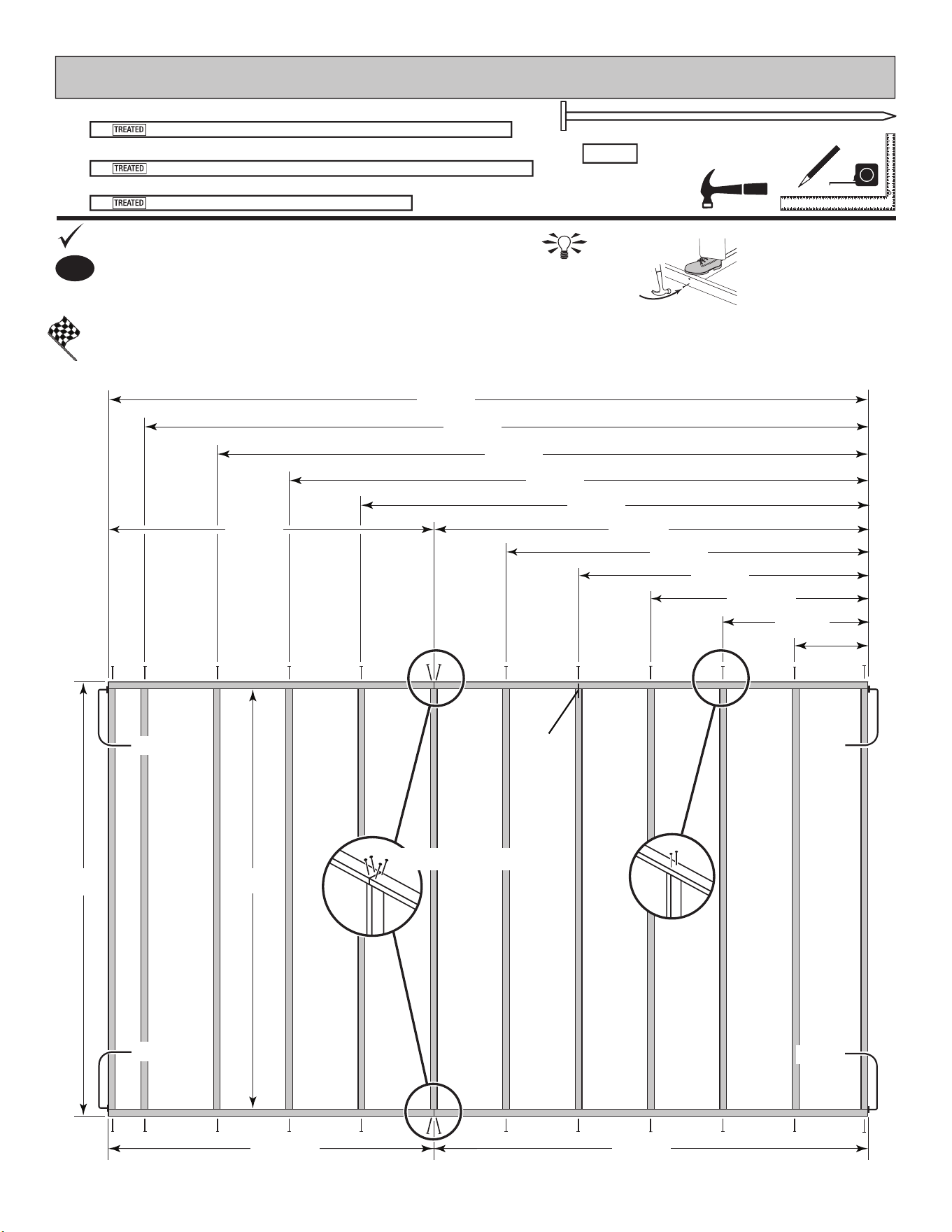
FLOOR FRAME
Look for
Stamp
TREATED
HINT:
For easier nailing
stand on frame.
1
Use two 3" nails at each mark.
Orient parts as shown on at surface. Measure and mark.
BEGIN
You have nished your oor frame. Proceed to level and square frame.
FINISH
Flush
Flush
Flush
Flush
TOENAILING
32"
(81,3 cm)
72"
(182,9 cm)
48"
(121,9 cm)
16"
(40,6 cm)
64"
(162,6 cm)
80"
(203,2 cm)
96"
(243,8 cm)
93"
(236,2 cm)
96"
(243,8 cm)
96"
(243,8 cm)
72"
(182,9 cm)
112"
(284,5 cm)
128"
(325,1 cm)
144"
(365,8 cm)
160"
(406,4 cm)
168"
(426,7 cm)
96"
(243,8 cm)
12
FINISH
4
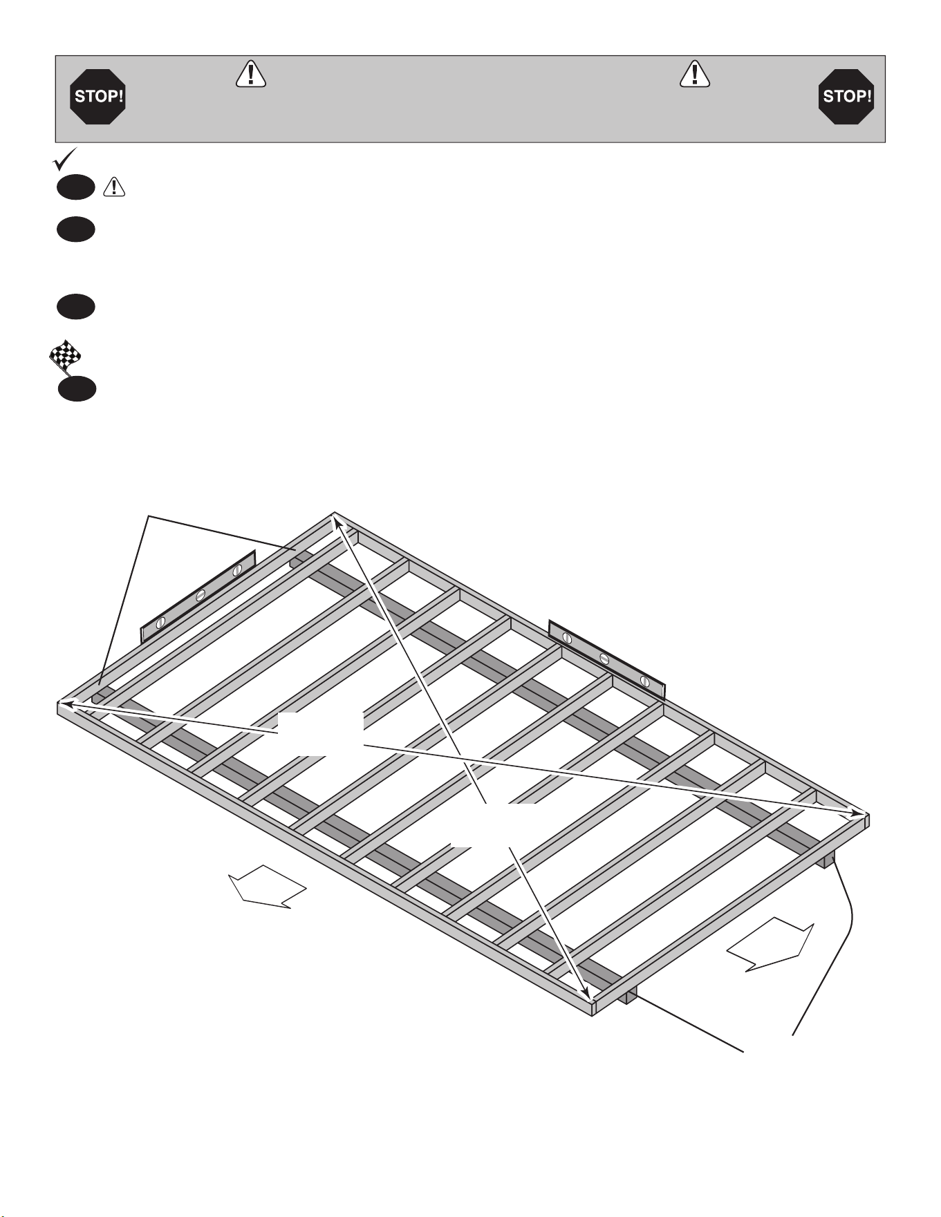
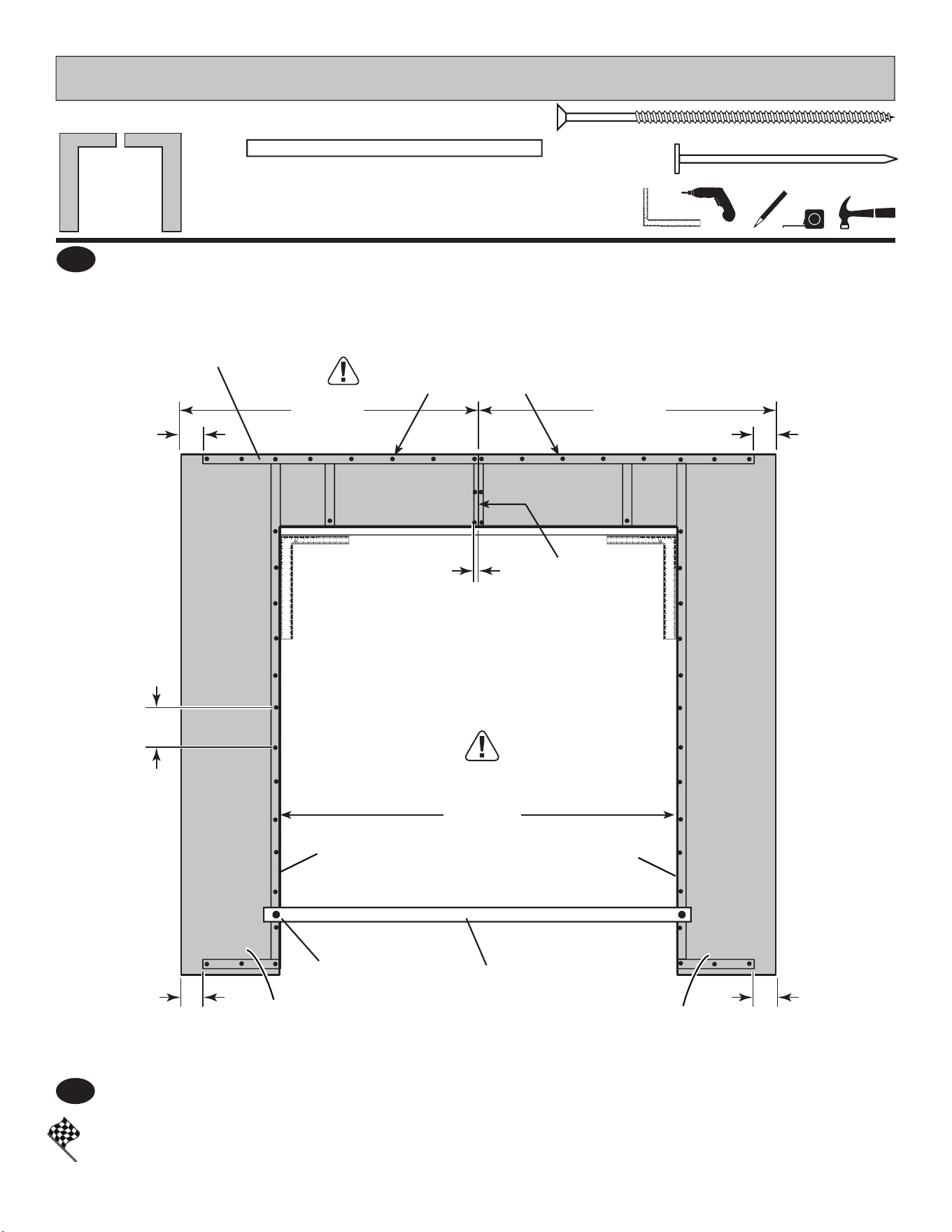
LEVEL AND SQUARE FLOOR FRAME
Before attaching oor decking, it is important to level and square the oor frame.
A level and square oor frame is required to correctly construct your shed.
BEGIN
2
3
1
Use level and check the frame is level before applying oor panels.
Check for frame squareness by measuring diagonally across corners. If the measurements are the
same, the frame is square. The diagonal measurement will be approximately 193-1/2" (491,5 cm).
When the frame is level and square secure one side of frame to the 4x4 runners using one fastener at
ends of each runner. Move to the opposite end of the frame. Secure the frame to 4x4 runners with one
fastener at ends of each runner making sure the frame remains square
(Fig. A).
Once the oor frame is level and square fasten the frame to the 4x4 runners at each point the frame
contacts the 4x4 runners.
See page 9 for the preferred oor leveling method.
First, secure
at ends with
one fastener.
Second, secure
at ends with
one fastener.
193-1/2"
(491,5 cm)
193-1/2"
(491,5 cm)
Fig. A
DOUBLE
DOOR
SINGLE
DOOR
13
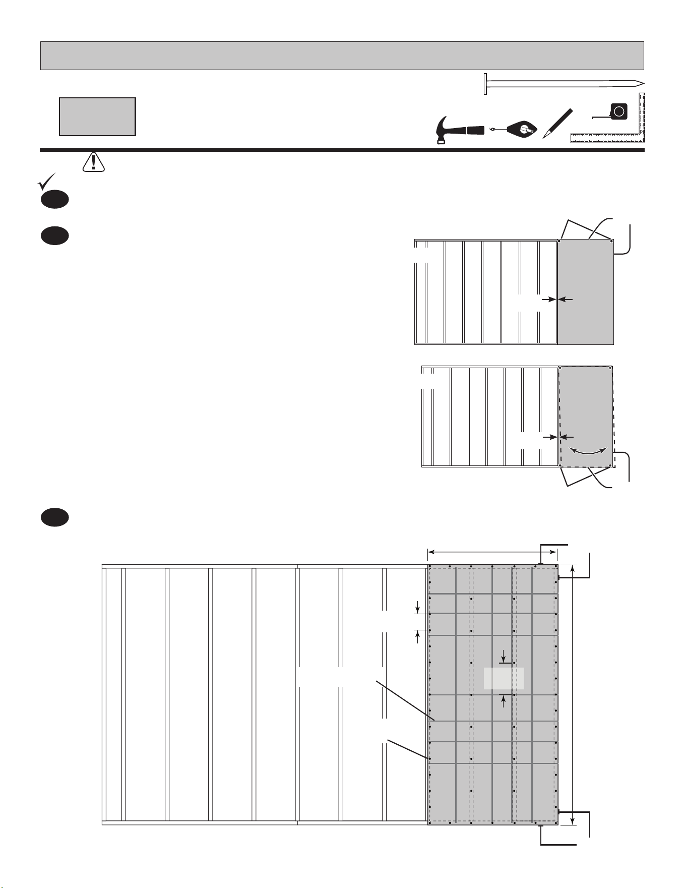
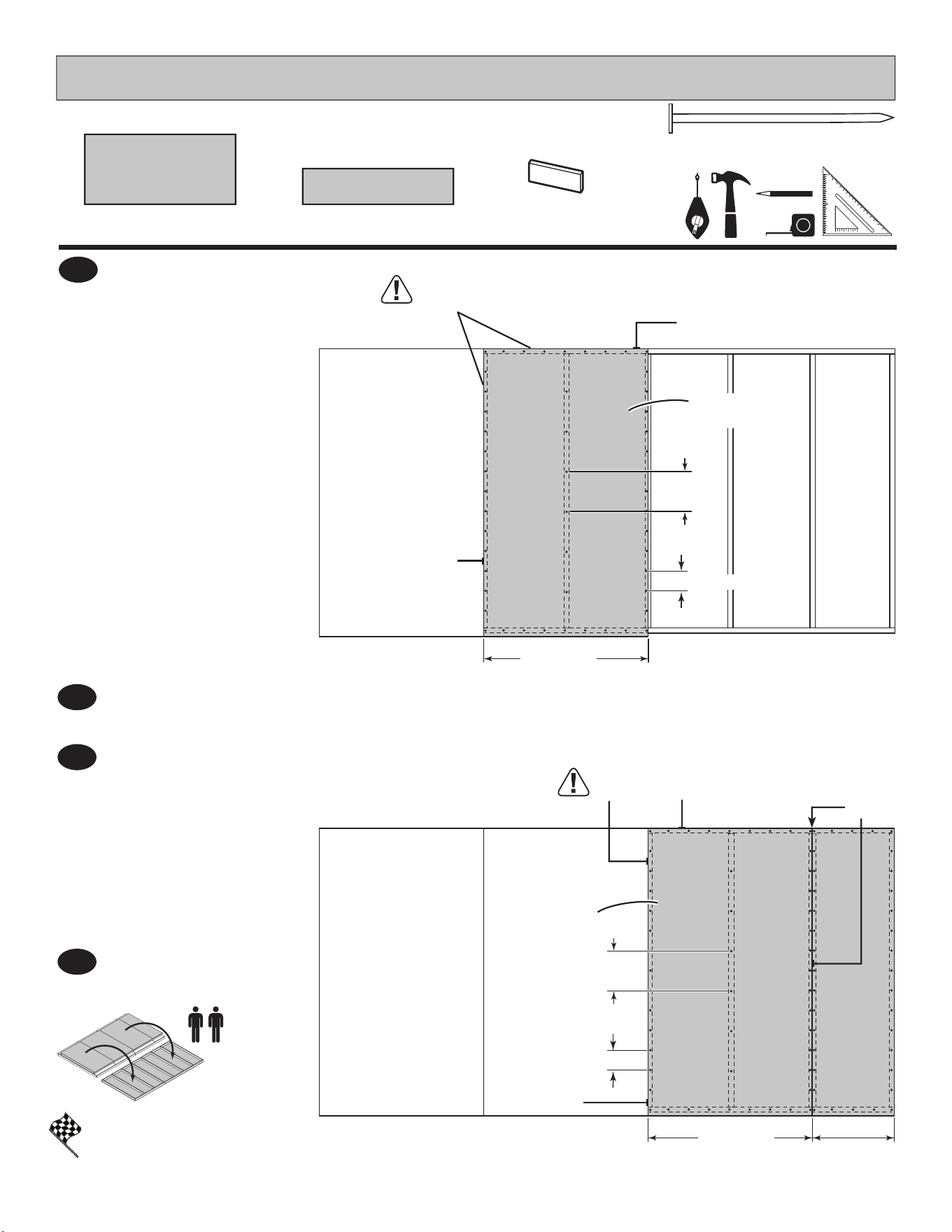
Move to the opposite side.
Using the long edge of the panel as a lever,
move the panel side-to-side until the top corner is ush
to the oor frame (Fig. B).
Secure panel with two 2" nails in the corners.
2
BEGIN
1
3
Continue attaching the panel using 2" nails 6" apart on edges and 12" apart inside panel.
Use a chalk line or use pre-painted grid lines to nail into joists under panel.
Ensure your oor frame is square by installing one panel and squaring frame.
PARTS REQUIRED:
x1
x219
5/8 x 48 x 96"
(1,6 x 121,9 x 243,8 cm)
2" (5,1 cm)
Grid lines up
FLOOR PANELS
Attach the 48 x 96" panel with the rough side up (painted-grid lines side) with the 48" edge and corner
ush to the oor frame (Fig A). Secure panel with two 2" nails in the corners.
Flush
Flush
6"
(15,2 cm)
12"
(30,5 cm)
Flush
(2) Nails
3/4"
(1,9 cm)
Fig. A
Flush
(2) Nails
3/4"
(1,9 cm)
Fig. B
2" (5,1 cm)
Nails
14
PARTS REQUIRED:
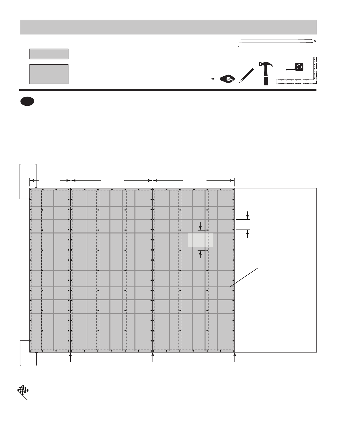
FINISH
You have nished attaching your oor panels.
Continue installing panels with rough side up (painted grid lines).
Use a chalk line or use pre-painted grid lines on panel for 2" nails 6" apart on edges,
and 12" apart inside panels.
4
FLOOR PANELS
Grid lines up
Flush
6"
(15,2 cm)
12"
(30,5 cm)
Flush Flush Flush Flush
2" (5,1 cm)
5/8" x 23-7/8" x 96" (1,6 x 60,6 x 243,8 cm)
x1
5/8" x 48" x 96" (1,6 x 121,9 x 243,8 cm)
x2
23-7/8"
(60,6 cm)
48"
(121,9 cm)
48"
(121,9 cm)
15
GABLE END
WALL
GABLE DOOR
WALL
BACK WALL
BACK WALL
Check the oor frame is level after installing oor panels.
Re-level if needed.
HINT:
IMPORTANT!
• The oor should be used as a stable work surface for wall construction.
• Organize your assembly procedure during the build process
to avoid over-handling of the walls.
FRONT WALL
(Your door location may vary.)
DOUBLE
DOOR
SINGLE
DOOR
16
PARTS REQUIRED:
FINISH
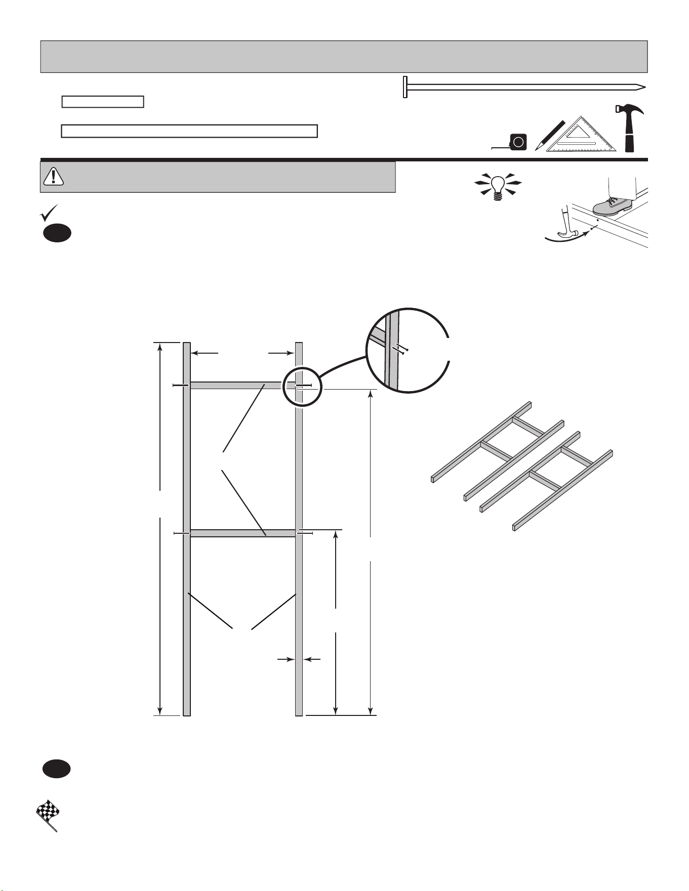
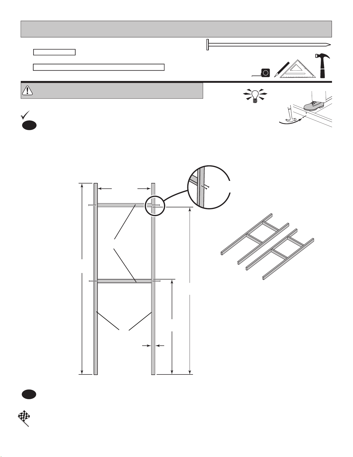
You have nished rafter jig. Proceed to assemble your rafters.
RAFTER ASSEMBLY
96"
(243,8 cm)
35-3/16"
(89,4 cm)
35-3/16"
(89,4 cm)
48"
(122 cm)
3/4"
(1,9 cm)
CPA CPA
CPA
3" (7,6 cm)
x6
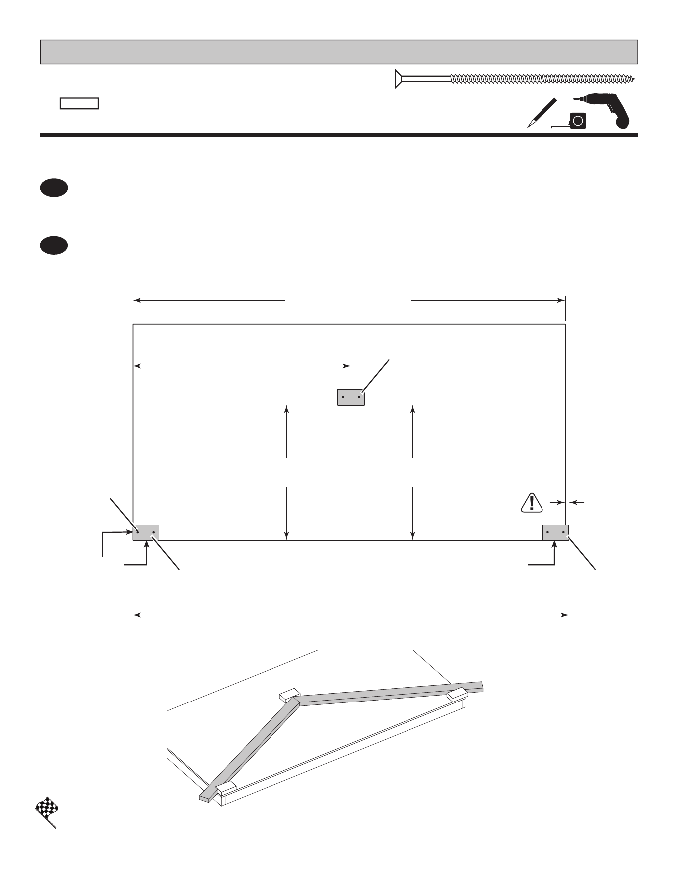
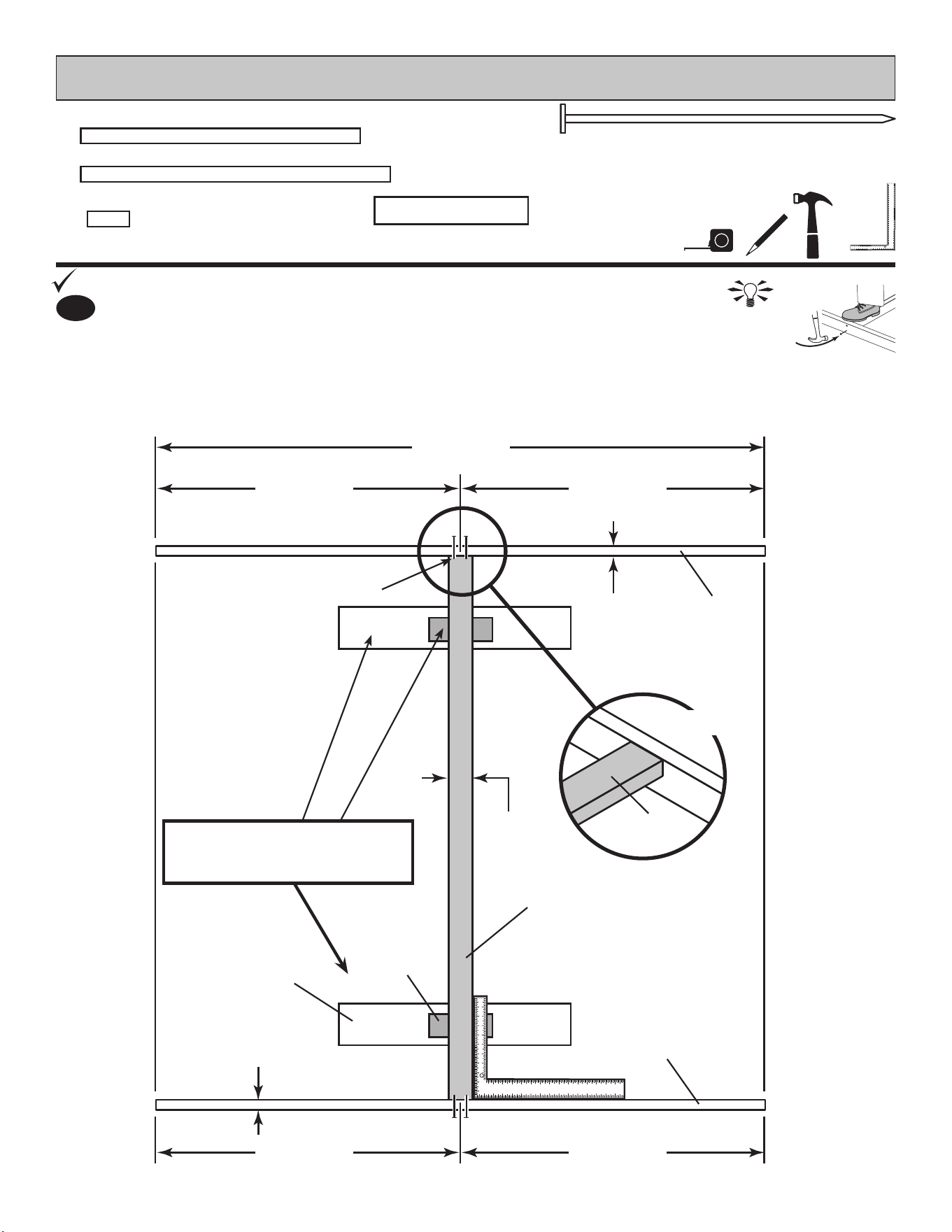
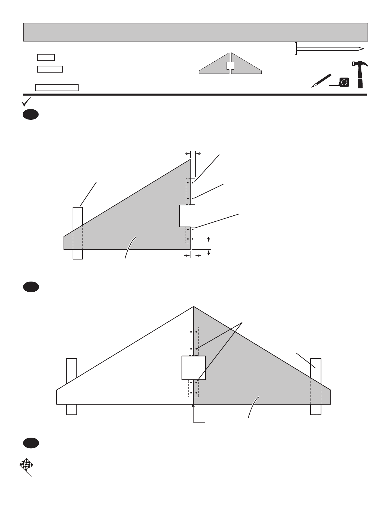
Measure over 48" and up 35-3/16" from the oor edges and secure CPA using two 3" screws.
Check CPA is 35-3/16" at both ends for squareness.
BEGIN
¸
1
Secure one CPA ush to the oor deck using two 3" screws.
Measure over 96-3/4" and install a second CPA ush to the oor deck. CPA will overhang the oor.
Secure using two 3" screws.
2
96-3/4"
(245,7 cm)
IMPORTANT MEASUREMENT !!
Fig. B
Fig. A
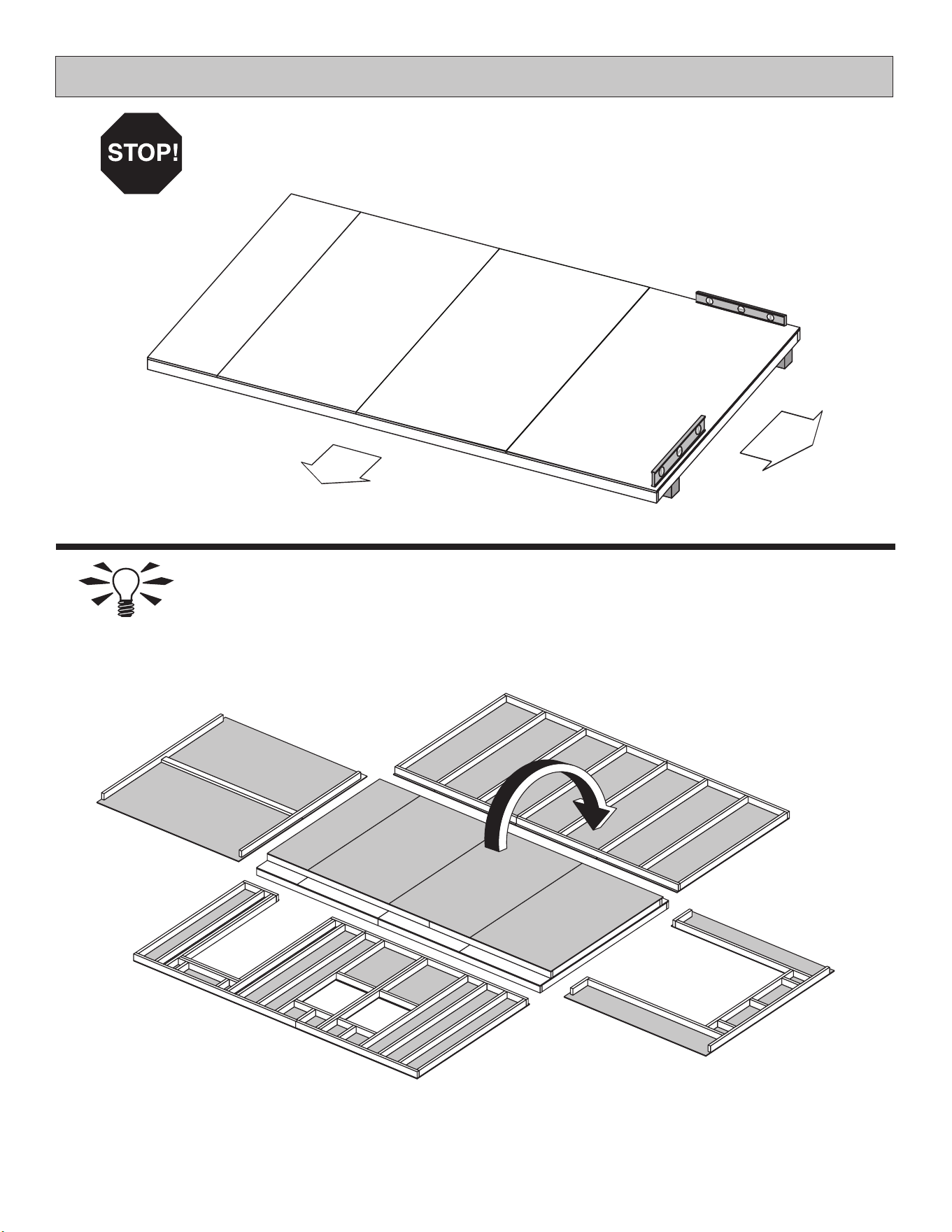
You will build a rafter jig using the oor and three CPA parts as shown.
Floor Width
(2) 3" (7,6 cm)
Screws
in each CPA
There will be an
overhang on
this end.
Flush Flush
x3
2 x 4 x 8-1/2" (5,1 x 10,2 x 21,6 cm)
CPA
17
PARTS REQUIRED:
x 168
2" (5,1 cm)
x 16
1-5/8" (4,1 cm)
RAFTER ASSEMBLY
You will build 8 rafters - Six with 2 gussets and Two with only 1 gusset.
x14
6 x 24" (15,2 x 61 cm)
OSB OR WOOD GRAIN
x16
2 x 4 x 63-7/8" (5,1 x 10,2 x 162,2 cm)
ASA
1/4" (1,9 cm)
GAP
1/4" (1,9 cm)
GAP
1/4" (1,9 cm)
GAP
1/4" (1,9 cm)
GAP
ASA x2
ASA x2
Fig. A
Fig. B
Fig. C
Glue where
gusset installs
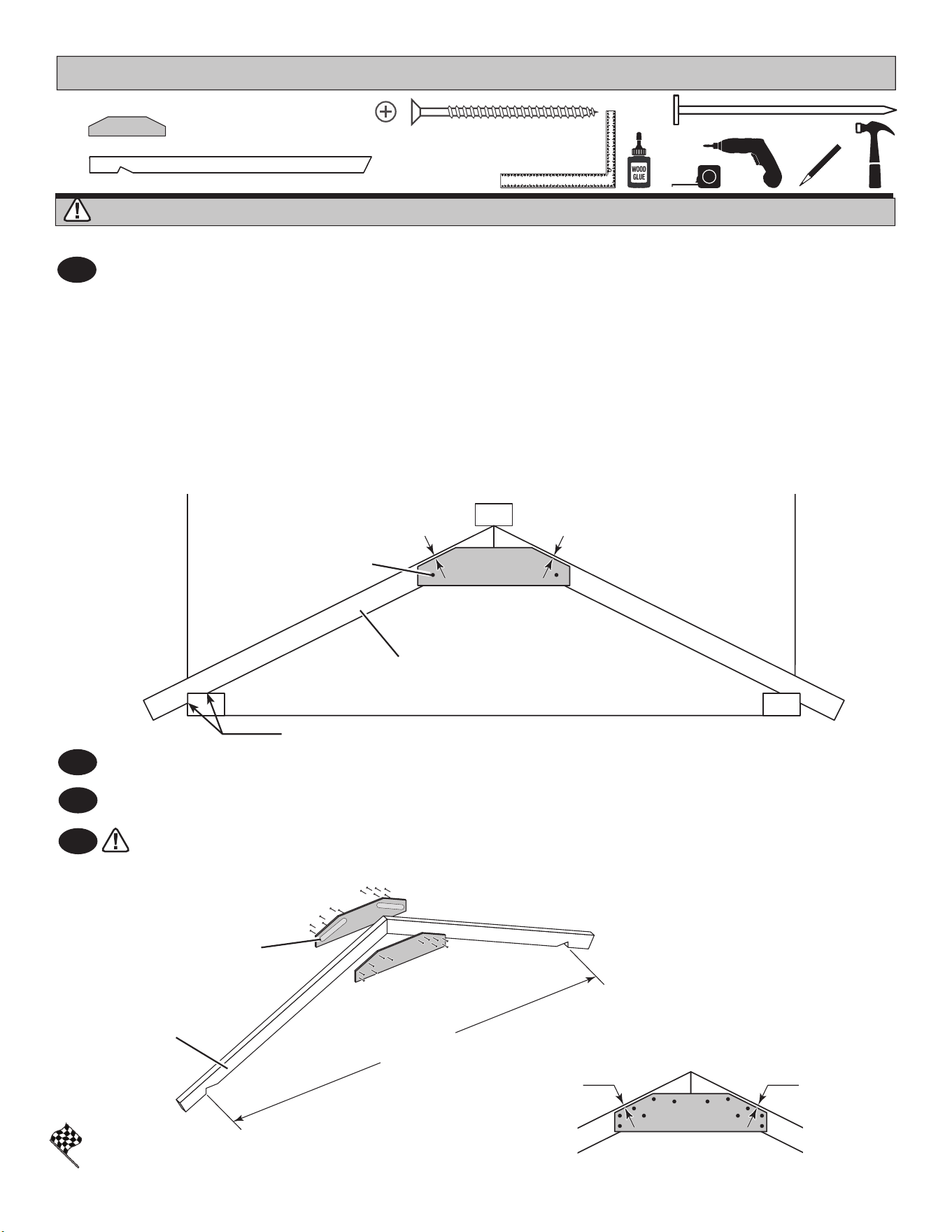
Keep rafters rmly against CPA at both ends when securing gusset.
You have nished assembling your rafters.
Repeat Steps 1 - 2 to assemble fi v e more rafters with 2 gussets.
Repeat Step 1 to assemble two more rafters with only
1 gusset.
Remove CPA's from oor.
Flip rafters over and attach a second gusset using glue and (12) 2" nails. No need to use jig for this gusset.
3
4
2
Keep ASA rm against outside CPA's as shown (Fig.A) and push rafters tight to the middle CPA. Rafters should
touch at tips (Fig. A).
Apply glue to rafters where gusset will attach (Fig. B).
Place gusset onto ASA holding a 1/4" gap from edge (Fig. C) and keeping rafters rm as instructed. Secure
gusset using one 1-5/8" screw into each rafter. HINT: These screws will help hold the measurements when you
nail on gussets.
Use ten 2" nails to nish securing the gusset to the rafters to pattern shown in Fig. C.
BEGIN
¸
1
Place two rafters ASA into the jig as shown.
FINISH
1-5/8" (4,1 cm)
Screw
96-3/4"
(245,7 cm)
x1
2 x 4 x 64" (5,1 x 10,2 x 162,6 cm)
UX
x2
2 x 4 x 80" (5 x 10,2 x 203,2 cm)
TK
18
HI NT:
For easier nailing
stand on frame.
x1
2 x 4 x 89" (5 x 10,2 x 226,1 cm)
SZ
PARTS REQUIRED:
3" (7,6 cm)
x24
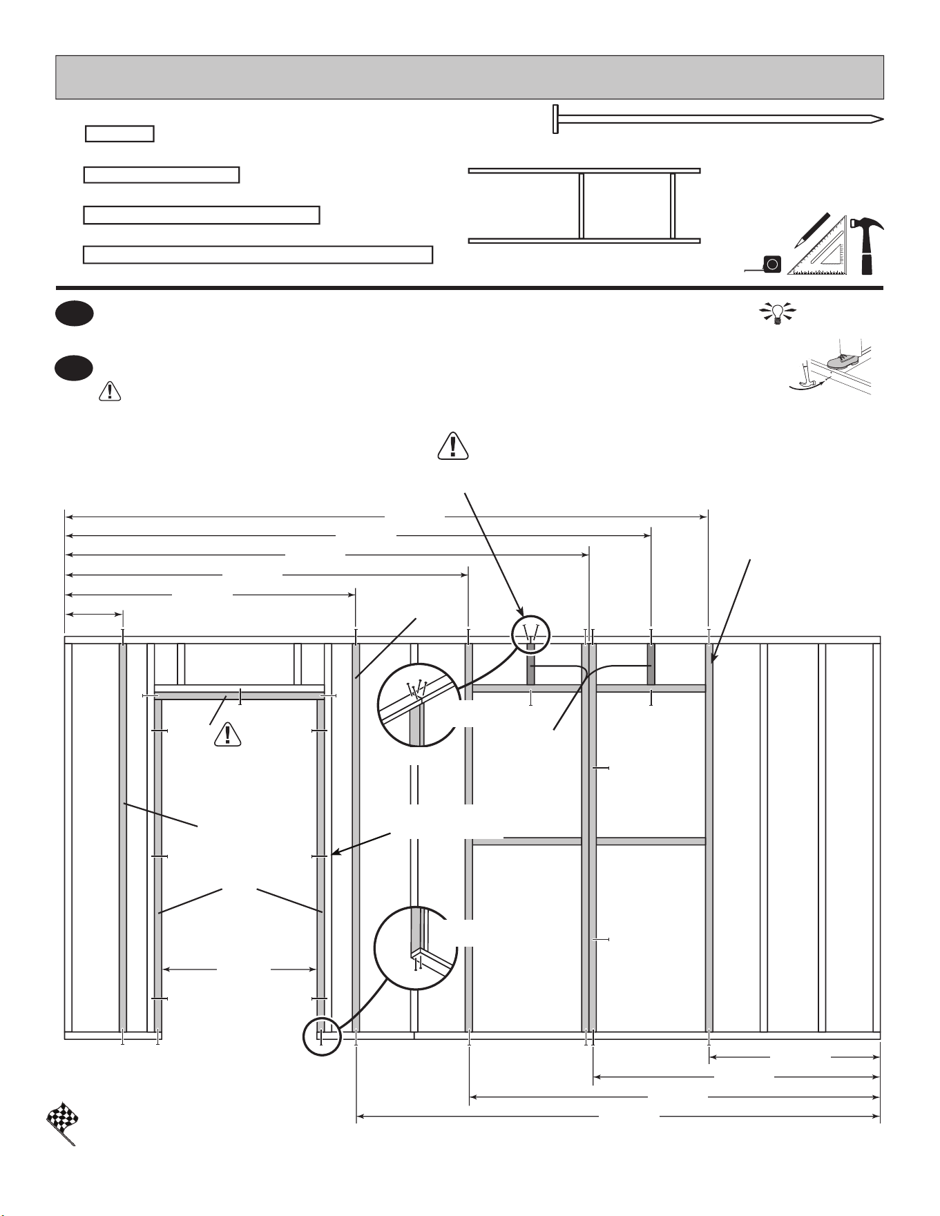
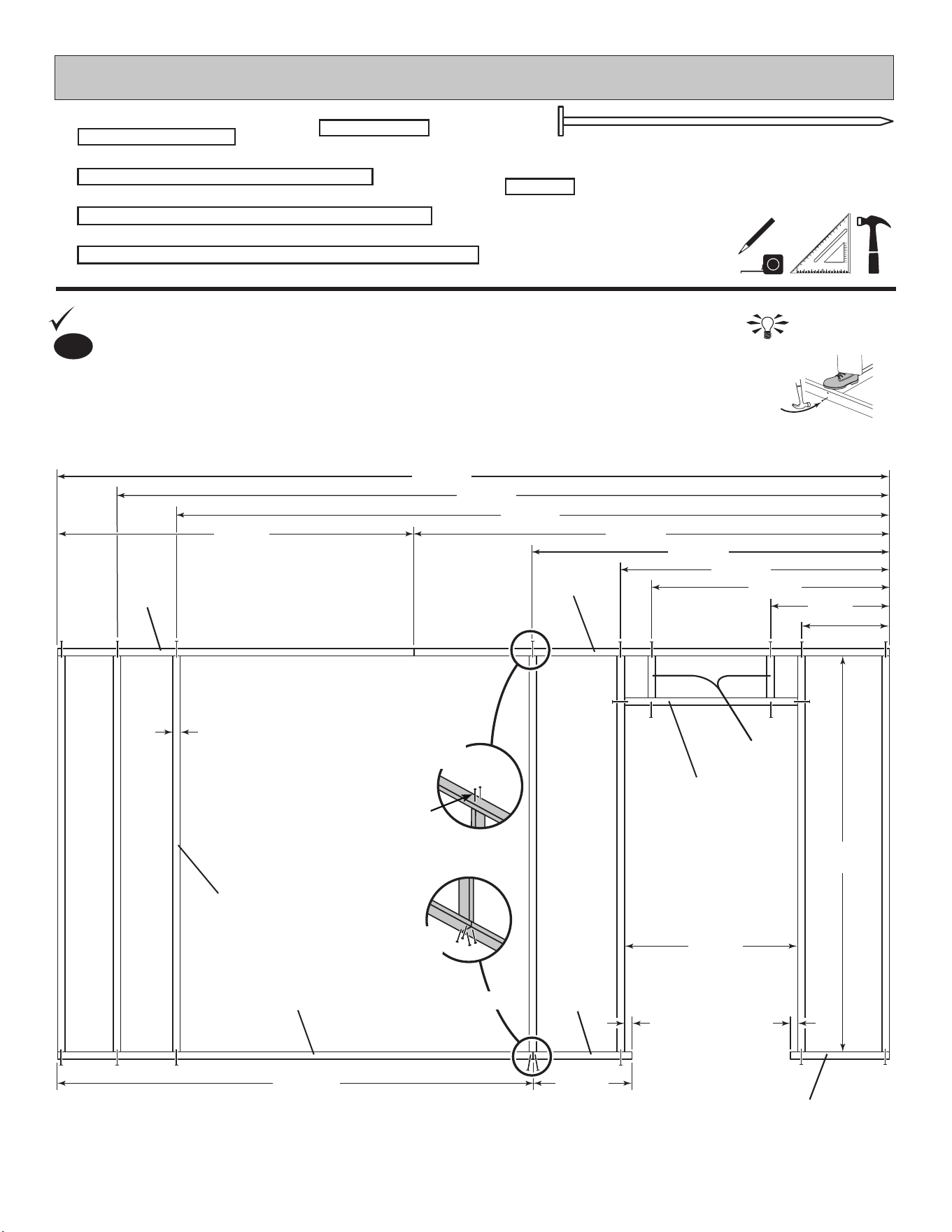
GABLE DOOR WALL
BEGIN
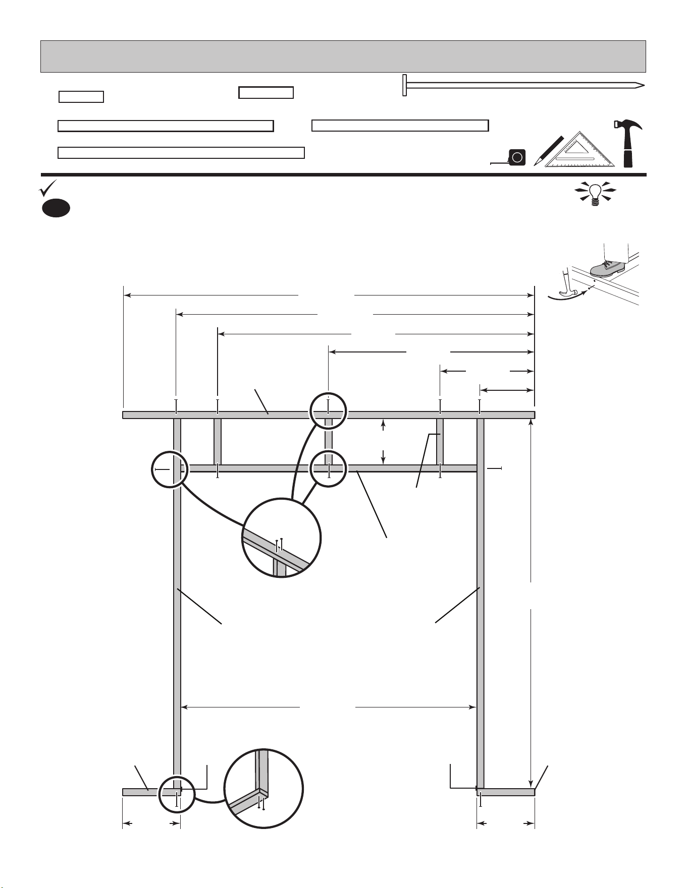
1
Use two 3" nails at each mark.
Orient parts on edge on oor. Measure and mark.
89"
(226,1 cm)
64"
(162,6 cm)
77-1/4"
(196,2 cm)
80"
(203,2 cm)
68-1/2"
(174 cm)
44-1/2"
(113 cm)
20-1/2"
(52,1 cm)
11-3/4"
(29,8 cm)
12-1/2"
(31,8 cm)
12-1/2"
(31,8 cm)
10"
(25,4 cm)
PWA x3
UX
TK
TK
3" (7,6 cm)
Nails
SZ
AJ AJ
x3
2 x 4 x 10" (5,1 x 10,2 x 25,4 cm)
PWA
x2
2 x 4 x 12-1/2" (5,1 x 10,2 x 31,8 cm)
AJ
Flush Flush
19
3/4"
1,9 cm
48"
(121,9 cm)
48"
(121,9 cm)
3-1/2"
(8,9 cm)
3-1/2"
(8,9 cm)
3-1/2"
(8,9 cm)
3-1/2"
(8,9 cm)
6"
(15,2 cm)
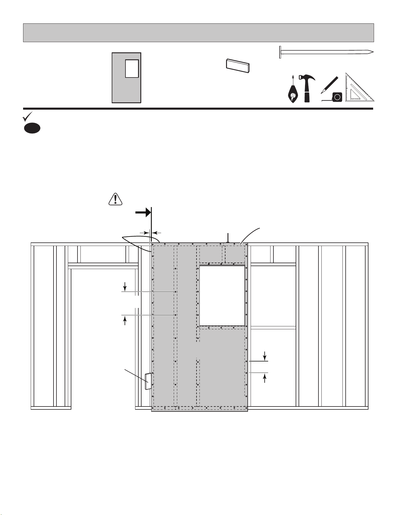
PARTS REQUIRED:
GABLE DOOR WALL
x52
2" (5,1 cm)
3" (7,6 cm)
x2
Place left 48" x 84" panel onto wall frame ush to top of SZ with primed
side up as shown. Secure panel with 2" nails 6" (15,2 cm) apart.
Repeat Step 2 to attach the right 48" x 84" panel.
2
You have nished building your gable door wall.
FINISH
48 x 84"
(121,9 x 213,4 cm)
x1 LEFT + 1 RIGHT
Maintain
Flush
Maintain
Flush
Primed
side up
Primed
side up
Flush
For squareness maintain ush
along panel edges.
Maintain 64" dimension
64"
(162,6 cm)
SZ
OO
3" (7,6 cm)
Screws
OO
x1
1-1/4 x 2-1/2 x 69" (3,2 x 6,3 x 175,3 cm)
Temporary support
3
Attach OO temporary support using 3" screws into wall frame as shown.
20
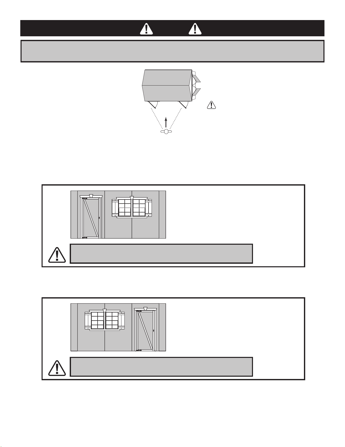
AS YOU FACE THE FRONT WALL, CHOOSE YOUR SINGLE DOOR LOCATION -
LEFT OR RIGHT
STOP
OPTION 2:
DOOR LOCATION
RIGHT SIDE OF FRONT WALL
IF YOU CHOOSE TO LOCATE THE DOOR TOWARD THE RIGHT
GO TO Page 27 TO BEGIN BUILDING YOUR WALL.
The single door is a reversible door and can
either be left hand swing or right hand swing,
depending on your preference.
The graphics referenced in this instruction
show the door as a left hand swing.
If you install the door as a right hand swing,
simply mirror the left hand door instructions.
OPTION 1:
DOOR LOCATION
LEFT SIDE OF FRONT WALL
IF YOU CHOOSE TO LOCATE THE DOOR TOWARD THE LEFT
GO TO Page 21 TO BEGIN BUILDING YOUR WALL.
If you choose to install your single door
on the right hand side of the shed and with
a right hand swing, note the double doors
and the single door will bump and interfere
with each other if opened at the same time.
Please be aware of this issue.
FRONT WALL
GABLE WALL DOUBLE DOORSIMPORTANT:
21
HINT:
For easier nailing
stand on frame.
PARTS REQUIRED:
FRONT WALL WITH DOOR LEFT
3" (7,6 cm)
x16
You will build two window frame assemblies (Fig.A).
Orient parts on edge on oor. Measure and mark.
80"
(203,2 cm)
TK
3" (7,6 cm)
Nails
1-1/2"
(3,8 cm)
BEGIN
1
Use two 3" nails at each mark.
Repeat Step 1 to build second window frame.
2
You have nished your window frame assemblies.
FINISH
4
22-1/2"
(5 7,1 c m)
Fig. A
AO
70"
(177, 8 c m)
40"
(101,6 cm)
x4
2 x 4 x 80" (5,1 x 10,2 x 203,2 cm)
TK
x4
2 x 4 x 22-1/2" (5,1 x 10,2 x 57,1 cm)
AO
FRONT WALL WITH DOOR LEFT
PARTS REQUIRED:
HINT:
For easier nailing
stand on frame.
22
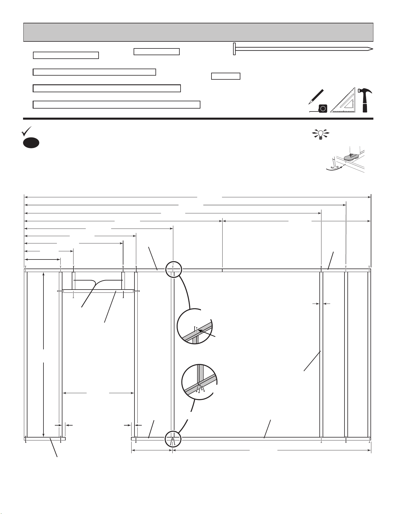
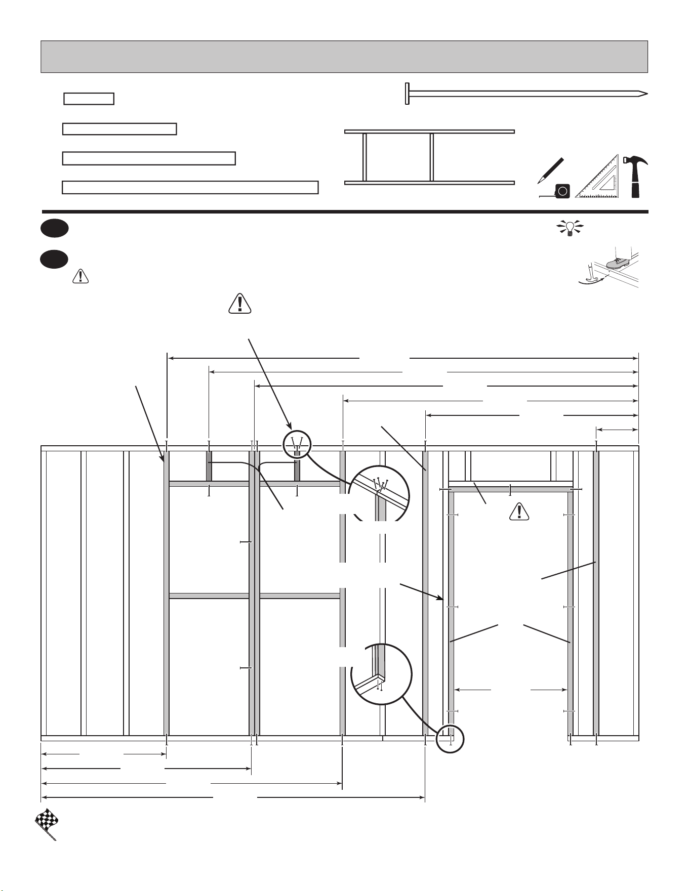
x42
3" (7,6 cm)
BEGIN
1
1-1/2"
(3,8 cm)
1-1/2"
(3,8 cm)
Orient parts on edge on oor. Measure and mark.
Use two 3" nails at each mark and four 3" nails at seams.
TK x7
CPA
TP
TP
ABA
ABA
QT
TM
TOENAILING
x2
2 x 4 x 96" (5,1 x 10,2 x 243,8 cm)
TP
x7
2 x 4 x 80" (5,1 x 10,2 x 203,2 cm)
TK
x2
2 x 4 x 20" (5,1 x 10,2 x 50,8 cm)
ABA
x2
2 x 4 x 8-1/2" (5,1 x 10,2 x 21,6 cm)
CPA
156"
(396,2 cm)
168"
(426,7 cm)
35"
(88,9 cm)
144"
(365,8 cm)
80"
(203,2 cm)
96"
(243,8 cm)
72"
(182,9) cm)
1-1/2"
(3,8 cm)
20"
(50,8 cm)
48"
(121,9 cm)
24"
(61 cm)
17-3/4"
(45,1 cm)
96"
(243,8 cm)
3" (7,6 cm)
Nails
3" (7,6 cm)
Nails
72"
(182,9 cm)
x1
2 x 4 x 35" (5,1 x 10,2 x 88,9 cm)
QT
54-1/4"
(137,8 cm)
Two 3" Nails at
each location.
x1
2 x 4 x 72" (5,1 x 10,2 x 182,9 cm)
TM
HINT:
For easier nailing
stand on frame.
23
FRONT WALL WITH DOOR LEFT
PARTS REQUIRED:
3" (7,6 cm)
x60
x2
2 x 4 x 80" (5,1 x 10,2 x 203,2 cm)
TK
TOENAILING
x2
2 x 4 x 8-1/2" (5,1 x 10,2 x 21,6 cm)
CPA
x2
2 x 4 x 68-1/2" (5,1 x 10,2 x 174 cm)
YFA
3
x1
2 x 4 x 35" (5,1 x 10,2 x 88,9 cm)
QT
60"
(152,4 cm)
83-1/4"
(211,5 cm)
108"
(274,3 cm)
108"
(274,3 cm)
120"
(337,2 cm)
132-3/4"
(304,8 cm)
12"
(30,5 cm)
32"
(81,3 cm)
QT
3" (7,6 cm)
Nails
3" (7,6 cm)
Nails
Two nails at
each location.
YFA
TK
TK
Window Frame
Assemblies
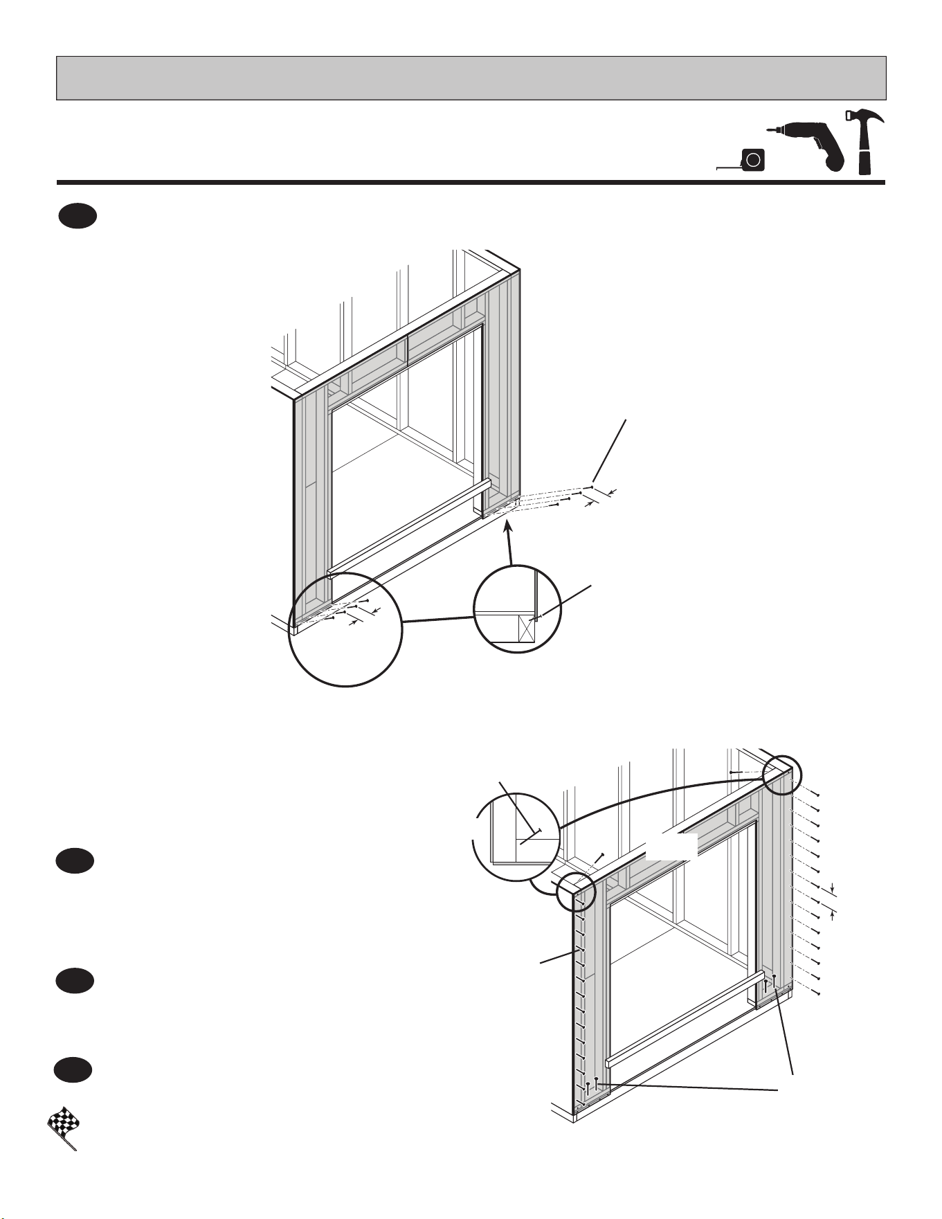
Install QT rst!
2
Place Sub-Assembly in frame as shown. Measure and mark.
Use two 3" nails at each mark and four 3" nails at seam.
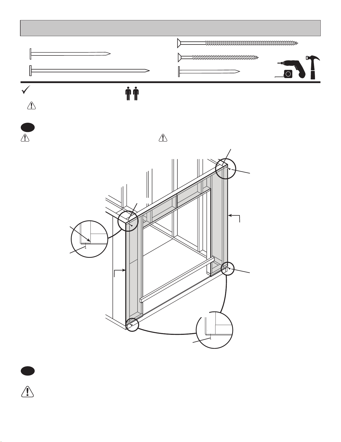
Orient door frame parts on edge on oor as shown. Measure and mark.
Install QT fi rst. Use two 3" nails at each mark as shown.
Hold Seam
Flush
CPA
84-3/4"
(215,3 cm)
59-1/4"
(151,5 cm)
35-1/4"
(89,5 cm)
You have nished your front wall frame.
FINISH
x2
Window Frame Assembly
24
FRONT WALL WITH DOOR LEFT
PARTS REQUIRED:
x63
2" (5,1 cm)
3/4" GAUGE
BLOCK
GAA
Flush
6"
(15,2 cm)
12"
(30,5 cm)
Primed
side up
3/4" GAUGE
BLOCK
x1
3/8 x 48 x 84"
(1 x 121,9 x 213,4 cm)
3/8 x 48 x 84"
(1 x 121,9 x 213,4 cm)
Place 48" x 84" window panel onto wall frame ush to top of frame with primed side up as shown.
Use the gauge block to mark the 3/4" measurement on the wall stud.
Secure panel with 2" nails 6" apart on edges and 12" apart inside panel.
BEGIN HERE
For squareness maintain Flush at
top of panel and 3/4" measurement
along panel edge.
3/4"
(1,9 cm)
BEGIN
1
25
FRONT WALL WITH DOOR LEFT
PARTS REQUIRED:
x66
2" (5,1 cm)
x1
3/8 x 48 x 84"
(1 x 121,9 x 213,4 cm)
Place 48 x 84" single door panel onto wall frame ush to top of frame with primed side up as shown.
Use the gauge block to mark the 3/4" measurement on the wall stud.
Secure panel with 2" nails 6" apart on edges
2
3/4" GAUGE
BLOCK
GAA
3/4"
(1,9 cm)
6"
(15,2 cm)
For squareness maintain ush and
3/4" measurement along panel edge.
Primed
side up
Flush
Flush
3/4" GAUGE
BLOCK
Flush
3/8 x 48 x 84"
(1 x 121,9 x 213,4 cm)
FRONT WALL WITH DOOR LEFT
26
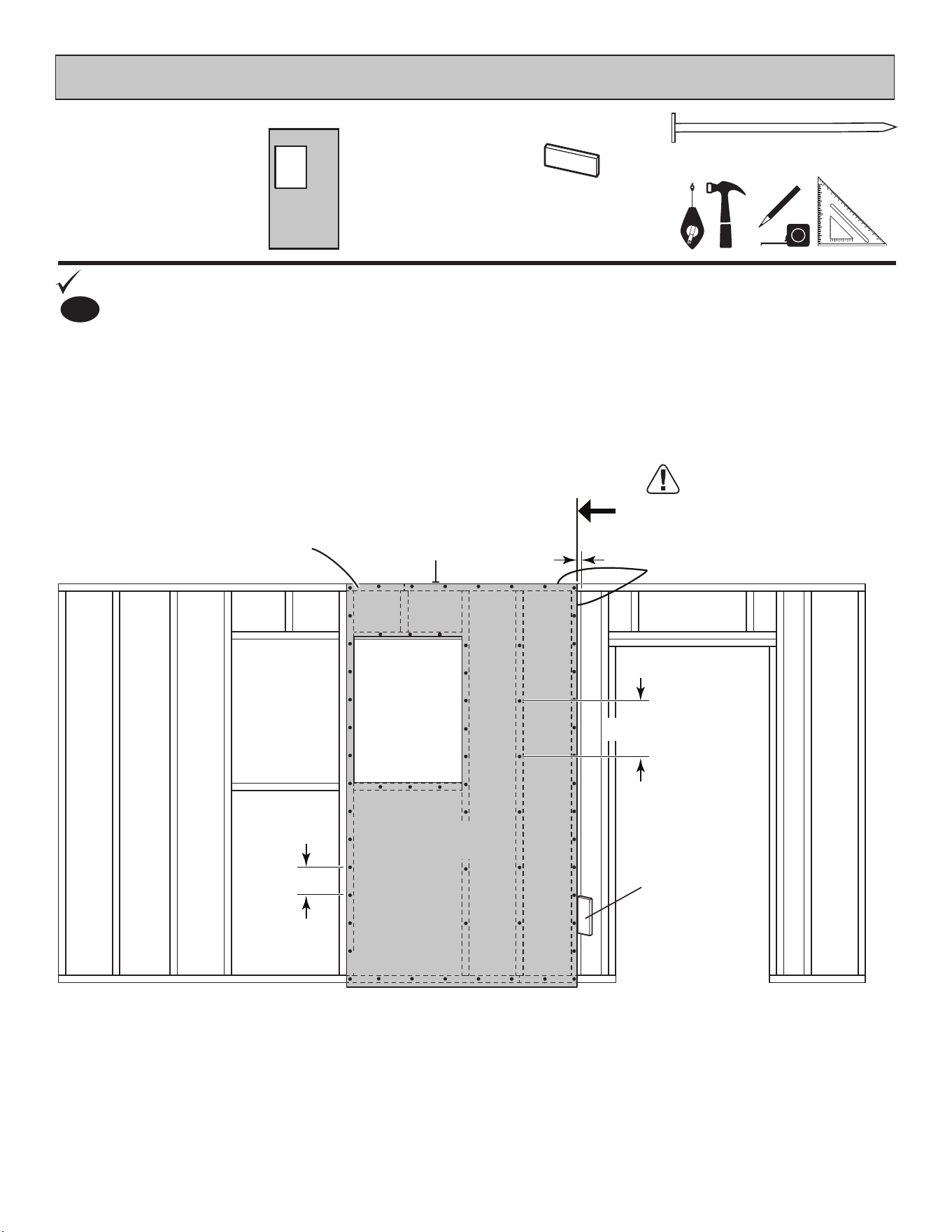
You have nished building your front wall.
FINISH
6
Carefully ip the front wall over.
PARTS REQUIRED:
x127
2" (5,1 cm)
x2
3/8 x 11-7/8 x 84"
(1 x 30,2 x 213,4 cm)
3" (7,6 cm)
x2
3
Primed
side up
Primed
side up
For squareness maintain
ush along panel edges.
Flush
Flush
FlushFlush
Go to page 33.
6"
(15,2 cm)
12"
(30,5 cm)
32"
(81,3 cm)
Flush Flush
3" (7,6 cm)
Screws
ATA
Temporary Support
Place 11-7/8" x 84" end panels primed side up onto wall frame, ush to top of frame
and ush to installed panels.
Secure panel with 2" nails 6" apart on edges and 12" apart inside panel.
4
5
Attach ATA temporary support using 3" screws into wall frame as shown.
Hold the 32" (81,3 cm) dimension.
x1
3/8 x 48 x 84"
(1 x 121,9 x 213,4 cm)
3/8 x 48 x 84"
(1 x 121,9 x 213,4 cm)
3/8 x 11-7/8 x 84"
(1 x 30,2 x 213,4 cm)
3/8 x 11-7/8 x 84"
(1 x 30,2 x 213,4 cm)
Place 2nd 48" x 84" window panel primed side up onto wall frame, ush to top of frame and ush to
installed panel. Use the gauge block to mark the 3/4" measurement on the wall stud.
Secure panel with 2" nails 6" apart on edges and 12" apart inside panel.
ATA Temporary Support
x1
2 x 4 x 64-1/8" (5,1 x 10,2 x 162,9 cm)
27
HINT:
For easier nailing
stand on frame.
PARTS REQUIRED:
FRONT WALL WITH DOOR RIGHT
3" (7,6 cm)
x16
You will build two window frame assemblies (Fig.A).
Orient parts on edge on oor. Measure and mark.
80"
(203,2 cm)
TK
3" (7,6 cm)
Nails
1-1/2"
(3,8 cm)
BEGIN
1
Use two 3" nails at each mark.
Repeat Step 1 to build second window frame.
2
You have nished your window frame assemblies.
FINISH
22-1/2"
(5 7,1 c m)
Fig. A
AO
70"
(177, 8 c m)
40"
(101,6 cm)
x4
2 x 4 x 80" (5,1 x 10,2 x 203,2 cm)
TK
x4
2 x 4 x 22-1/2" (5,1 x 10,2 x 57,1 cm)
AO
FRONT WALL WITH DOOR RIGHT
PARTS REQUIRED:
HINT:
For easier nailing
stand on frame.
28
x42
3" (7,6 cm)
BEGIN
1
1-1/2"
(3,8 cm)
1-1/2"
(3,8 cm)
Orient parts on edge on oor. Measure and mark.
Use two 3" nails at each mark and four 3" nails at seams.
TK x7
CPA
TP
TP
ABA
ABA
QT
TM
TOENAILING
x2
2 x 4 x 96" (5,1 x 10,2 x 243,8 cm)
TP
x7
2 x 4 x 80" (5,1 x 10,2 x 203,2 cm)
TK
x2
2 x 4 x 20" (5,1 x 10,2 x 50,8 cm)
ABA
x2
2 x 4 x 8-1/2" (5,1 x 10,2 x 21,6 cm)
CPA
156"
(396,2 cm)
168"
(426,7 cm)
35"
(88,9 cm)
144"
(365,8 cm)
80"
(203,2 cm)
96"
(243,8 cm)
72"
(182,9) cm)
1-1/2"
(3,8 cm)
20"
(50,8 cm)
48"
(121,9 cm)
24"
(61 cm)
17-3/4"
(45,1 cm)
96"
(243,8 cm)
3" (7,6 cm)
Nails
3" (7,6 cm)
Nails
72"
(182,9 cm)
x1
2 x 4 x 35" (5,1 x 10,2 x 88,9 cm)
QT
54-1/4"
(137,8 cm)
Two 3" Nails at
each location.
x1
2 x 4 x 72" (5,1 x 10,2 x 182,9 cm)
TM
HINT:
For easier nailing
stand on frame.
29
FRONT WALL WITH DOOR RIGHT
PARTS REQUIRED:
3" (7,6 cm)
x60
x2
2 x 4 x 80" (5,1 x 10,2 x 203,2 cm)
TK
TOENAILING
x2
2 x 4 x 8-1/2" (5,1 x 10,2 x 21,6 cm)
CPA
x2
2 x 4 x 68-1/2" (5,1 x 10,2 x 174 cm)
YFA
3
x1
2 x 4 x 35" (5,1 x 10,2 x 88,9 cm)
QT
60"
(152,4 cm)
83-1/4"
(211,5 cm)
108"
(274,3 cm)
12"
(30,5 cm)
32"
(81,3 cm)
QT
3" (7,6 cm)
Nails
3" (7,6 cm)
Nails
Two nails at
each location.
YFA
TK
TK
Window Frame
Assemblies
Install QT rst!
2
Place Sub-Assembly in frame as shown. Measure and mark.
Use two 3" nails at each mark and four 3" nails at seam.
Orient parts on edge on oor as shown. Measure and mark.
Install QT fi rst. Use two 3" nails at each mark as shown.
Hold Seam
Flush
CPA
You have nished your front wall frame.
FINISH
x2
Window Frame Assembly
108"
(274,3 cm)
120"
(337,2 cm)
84-3/4"
(215,3 cm)
59-1/4"
(151,5 cm)
35-1/4"
(89,5 cm)
132-3/4"
(337,2 cm)
30
FRONT WALL WITH DOOR RIGHT
PARTS REQUIRED:
x63
2" (5,1 cm)
3/4" GAUGE
BLOCK
GAA
Flush
6"
(15,2 cm)
12"
(30,5 cm)
Primed
side up
3/4" GAUGE
BLOCK
x1
3/8 x 48 x 84"
(1 x 121,9 x 213,4 cm)
3/8 x 48 x 84"
(1 x 121,9 x 213,4 cm)
Place 48" x 84" window panel onto wall frame ush to top of frame with primed side up as shown.
Use the gauge block to mark the 3/4" measurement on the wall stud.
Secure panel with 2" nails 6" apart on edges and 12" apart inside panel.
BEGIN HERE
For squareness maintain Flush at
top of panel and 3/4" measurement
along panel edge.
3/4"
(1,9 cm)
BEGIN
1
31
FRONT WALL WITH DOOR RIGHT
PARTS REQUIRED:
x66
2" (5,1 cm)
x1
3/8 x 48 x 84"
(1 x 121,9 x 213,4 cm)
Place 48 x 84" single door panel onto wall frame ush to top of frame with primed side up as shown.
Use the gauge block to mark the 3/4" measurement on the wall stud.
Secure panel with 2" nails 6" apart on edges
2
3/4" GAUGE
BLOCK
GAA
3/4"
(1,9 cm)
6"
(15,2 cm)
For squareness maintain ush and
3/4" measurement along panel edge.
Primed
side up
Flush
Flush
3/4" GAUGE
BLOCK
Flush
3/8 x 48 x 84"
(1 x 121,9 x 213,4 cm)
EAVE SIDE WALL WITH DOOR RIGHT
32
You have nished building your front wall.
FINISH
6
Carefully ip the front wall over.
PARTS REQUIRED:
x127
2" (5,1 cm)
x2
3/8 x 11-7/8 x 84"
(1 x 30,2 x 213,4 cm)
3
Primed
side up
Primed
side up
For squareness maintain
ush along panel edges.
Flush
Flush
Flush Flush
6"
(15,2 cm)
12"
(30,5 cm)
FlushFlush
3" (7,6 cm)
Screws
32"
(81,3 cm)
Place 11-7/8" x 84" end panels primed side up onto wall frame, ush to top of frame
and ush to installed panels.
Secure panel with 2" nails 6" apart on edges and 12" apart inside panel.
4
5
Attach ATA temporary support using 3" screws into wall frame as shown.
Hold the 32" (81,3 cm) dimension.
x1
3/8 x 48 x 84"
(1 x 121,9 x 213,4 cm)
3/8 x 48 x 84"
(1 x 121,9 x 213,4 cm)
3/8 x 11-7/8 x 84"
(1 x 30,2 x 213,4 cm)
3/8 x 11-7/8 x 84"
(1 x 30,2 x 213,4 cm)
Place 2nd 48" x 84" window panel primed side up onto wall frame, ush to top of frame and
ush to installed panel.
Use the gauge block to mark the 3/4" measurement on the wall stud.
Secure panel with 2" nails 6" apart on edges and 12" apart inside panel.
ATA
Temporary Support
ATA Temporary Support
x1
2 x 4 x 64-1/8" (5,1 x 10,2 x 162,9 cm)
BACK WALL
PARTS REQUIRED:
96"
(243,8 cm)
120"
(312,4 cm)
72"
(182,9 cm)
72"
(182,9 cm)
48"
(121,9 cm)
24"
(61 cm)
80"
(203,2 cm)
1-1/2"
(3,8 cm)
144"
(356,8 cm)
168"
(426,7 cm)
96"
(243,8 cm)
72"
(182,9 cm)
TK x8
TP
TM
TM
TP
HINT:
For easier nailing
stand on frame.
x2
2 x 4 x 96" (5,1 x 10,2 x 243,8 cm)
TP
x8
2 x 4 x 80" (5,1 x 10,2 x 203,2 cm)
TK
33
x36
3" (7,6 cm)
BEGIN
1
Orient parts on edge on oor. Measure and mark.
Use two 3" nails at each mark and four 3" nails at seams
TOENAILING
x2
2 x 4 x 72" (5,1 x 10,2 x 182,9 cm)
TM
34
BACK WALL
PARTS REQUIRED:
48 x 84"
(121,9 x 213,4 cm)
x1
x50
2" (5,1 cm)
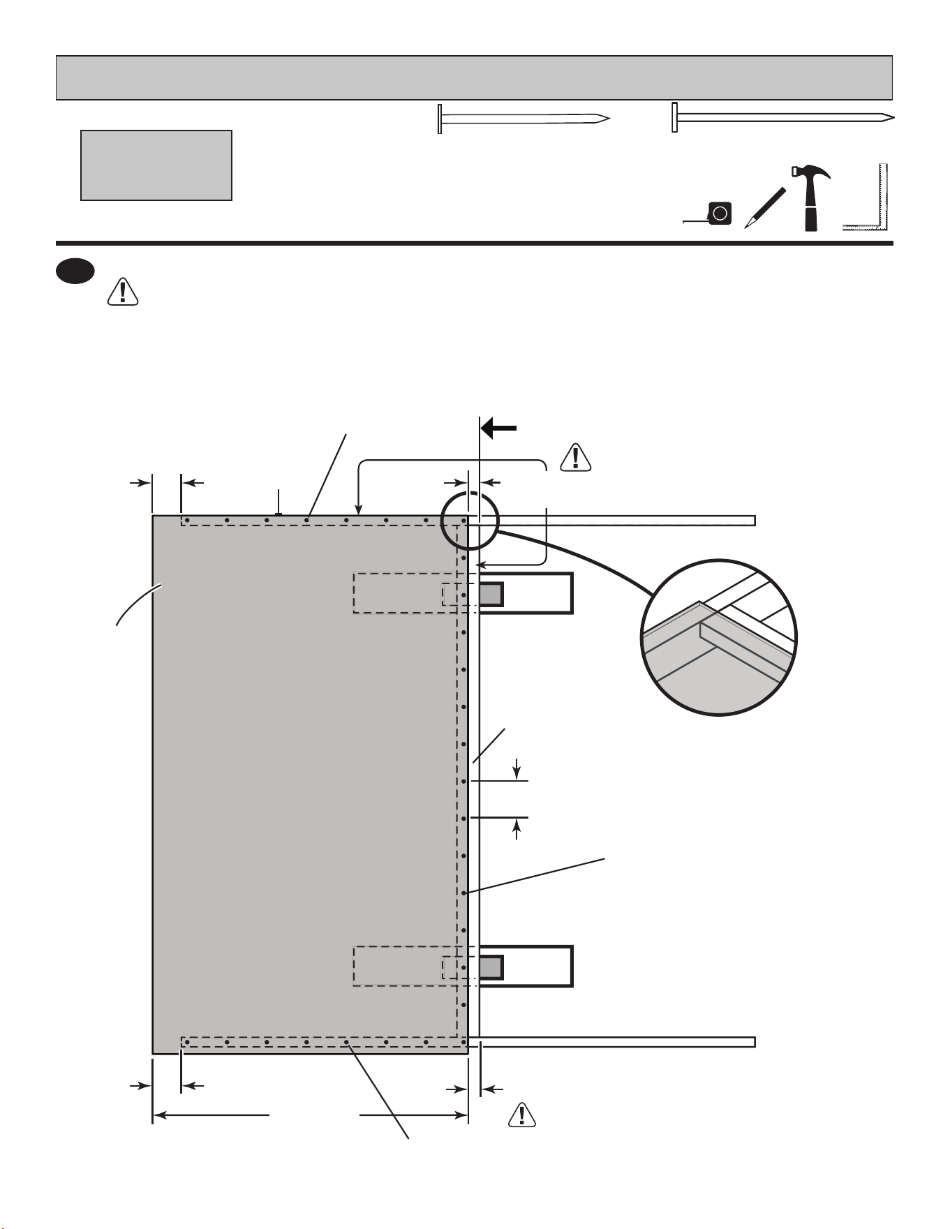
Place 1st 48 x 84" panel onto wall frame ush to top of frame with primed side up as shown.
Use the gauge block to mark the 3/4" measurement on the wall stud. Secure panel with two 2"
nails in the corners (Fig. A).
Nail the panel using 2" nails 6" apart on edges and 12" apart inside panel.
Ensure your wall frame is square by installing one panel and squaring frame.
Move to the opposite end. Using the long edge of the panel as a lever move the panel side-to-side until you have
a 3/4" measurement on the wall stud. Secure corner with two 2" nails (Fig. B).
3
2
3/4" GAUGE
BLOCK
GAA
2 Nails
Fig. B
Fig. A
3/4"
(1,9 cm)
3/4"
(1,9 cm)
2 Nails
3/4" GAUGE
BLOCK
BEGIN HERE
Flush
3/4"
(1,9 cm)
6"
(15,2 cm)
12"
(30,5 cm)
48"
(121,9 cm)
For squareness maintain ush and
3/4" measurement along panel edge.
Primed
side up
35
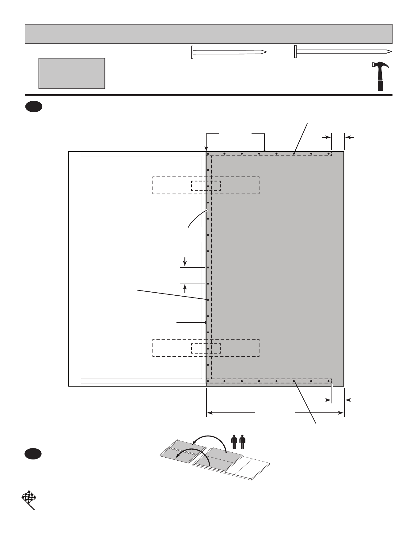
Place 2nd 48" x 84" panel on frame as
shown with primed side facing up.
Nail using 2" nails 6" apart on edges
and 12" apart inside panel.
4
Place 3rd 48" x 84" panel on frame as shown with primed side facing up.
Nail using 2" nails 6" apart on edges and 12" apart inside panel.
Place end 23-7/8" x 84" panel on frame as
shown with primed side facing up.
Nail using 2" nails 6" apart on edges.
5
6
You have nished building your back wall.
FINISH
x2 x1
x136
BACK WALL
PARTS REQUIRED:
2" (5,1 cm)
7
Carefully ip the
back wall over.
3/4" GAUGE
BLOCK
GAA
48 x 84"
(121,9 x 213,4 cm)
23-7/8 x 84"
(60,6 x 213,4 cm)
For squareness maintain ush and 3/4"
measurement along panel edges.
Primed
side up
6" (15,2 cm)
12"
(30,5 cm)
48"
(121,9 cm)
Flush
Flush
For squareness maintain ush and 3/4"
measurement along panel edges.
Primed
side up
6" (15,2 cm)
12"
(30,5 cm)
48"
(121,9 cm)
23-7/8"
(60,6 cm)
Flush
Flush
PARTS REQUIRED:
x2
2 x 4 x 89" (5 x 10,2 x 226,1 cm)
SZ
x1
2 x 4 x 80" (5 x 10,2 x 203,2 cm)
TK
x4
3" (7,6 cm)
36
GABLE END WALL
TK
TK
SZ
SZ
HI NT:
For easier nailing
stand on frame.
BEGIN
1
3-1/2"
(8,9 cm)
1-1/2"
(3,8 cm)
1-1/2"
(3,8 cm)
44-1/2"
(113 cm)
44-1/2"
(113 cm)
Fig. A
89"
(76,2 cm)
44-1/2"
(113 cm)
44-1/2"
(113 cm)
3" (7,6 cm)
Two Nails at each end.
Temporary support
x2
19/32 x 5-1/2 x 30-1/8"
(1,5 x 14 x 76,5 cm)
DHA
Temporary support
x2
2 x 4 x 6"
(5,1 x 10,2 x 15,2 cm)
PVA
Orient parts on oor. TK is on at side (Fig.A).
Support center stud TK with temporary supports DHA and PVA as shown.
Measure, mark and square.
Use two 3" nails at each connection.
PVA
DHA
Temporary Support - stack one
PVA (2 x 4") and one
DHA (5-1/2 x 30-1/8").
PARTS REQUIRED:
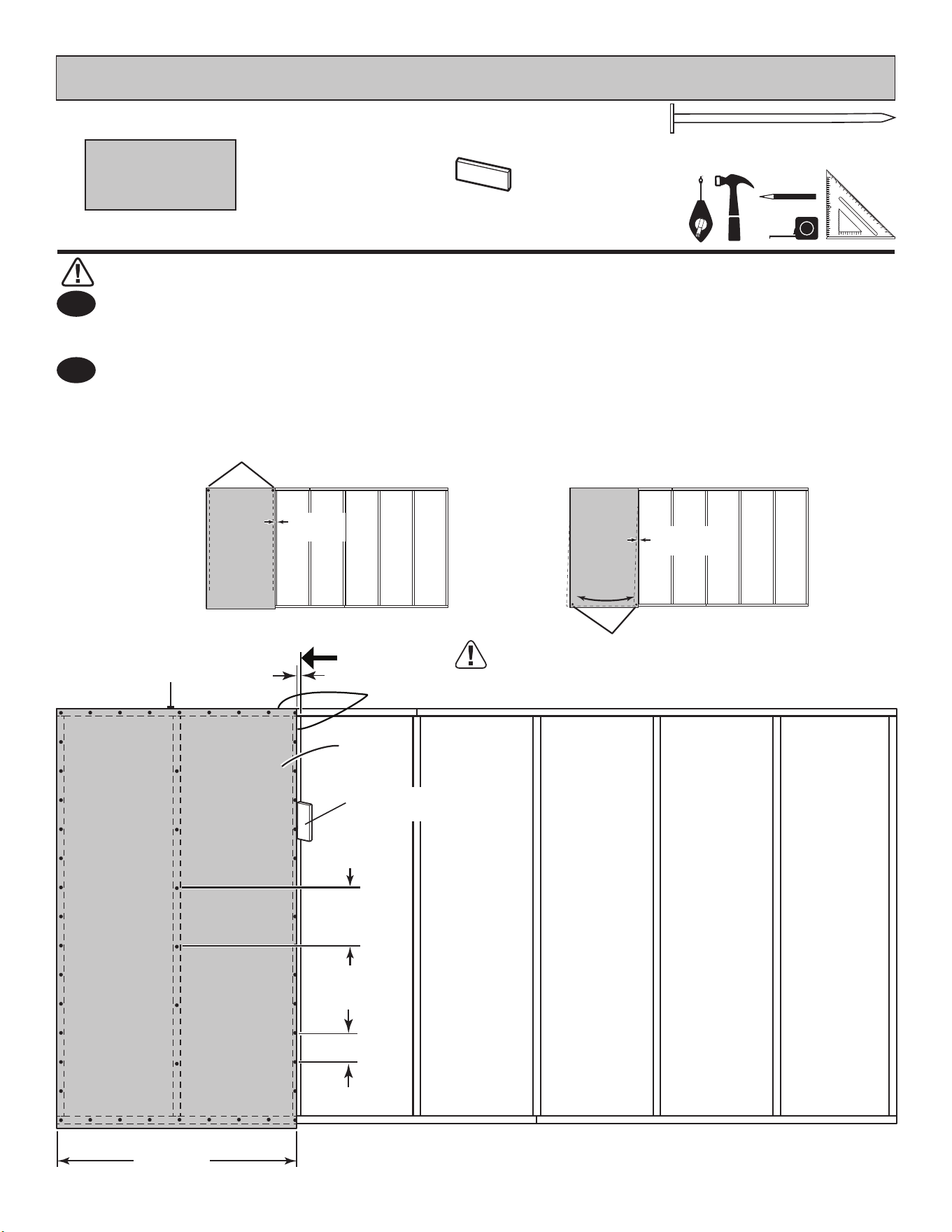
x16
2" (5,1 cm)
x13
1-1/2" (3,8 cm)
37
GABLE END WALL
48 x 84"
(121,9 x 213,4 cm)
x1
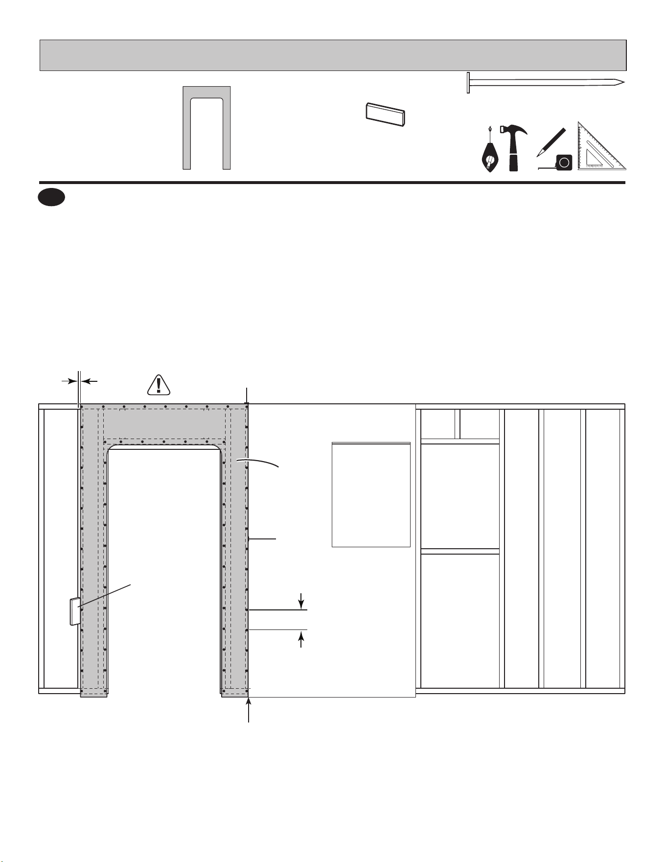
BEGIN HERE
Secure panel to top and bottom plate using 2" nails 6" (15,2 cm) apart along edges.
Secure panel to TK with 1-1/2" nails.
Place 48 x 84" panel with primed side up onto frame ush at top and with a 1-3/4" gap along right side.
Maintain 1-3/4" measurement along edge.
For squareness maintain ush and
1-3/4" measurement along panel edges.
2
1-3/4"
(4,4 cm)
1-3/4"
(4,4 cm)
3-1/2"
(8,9 cm)
3-1/2"
(8,9 cm)
Primed
side up
48"
(121,9 cm)
6"
(15,2 cm)
TK
Flush
1-1/2"
(3,8 cm)
Nails
2" (5,1 cm)
Nails
2" (5,1 cm)
Nails
38
PARTS REQUIRED:
GABLE END WALL
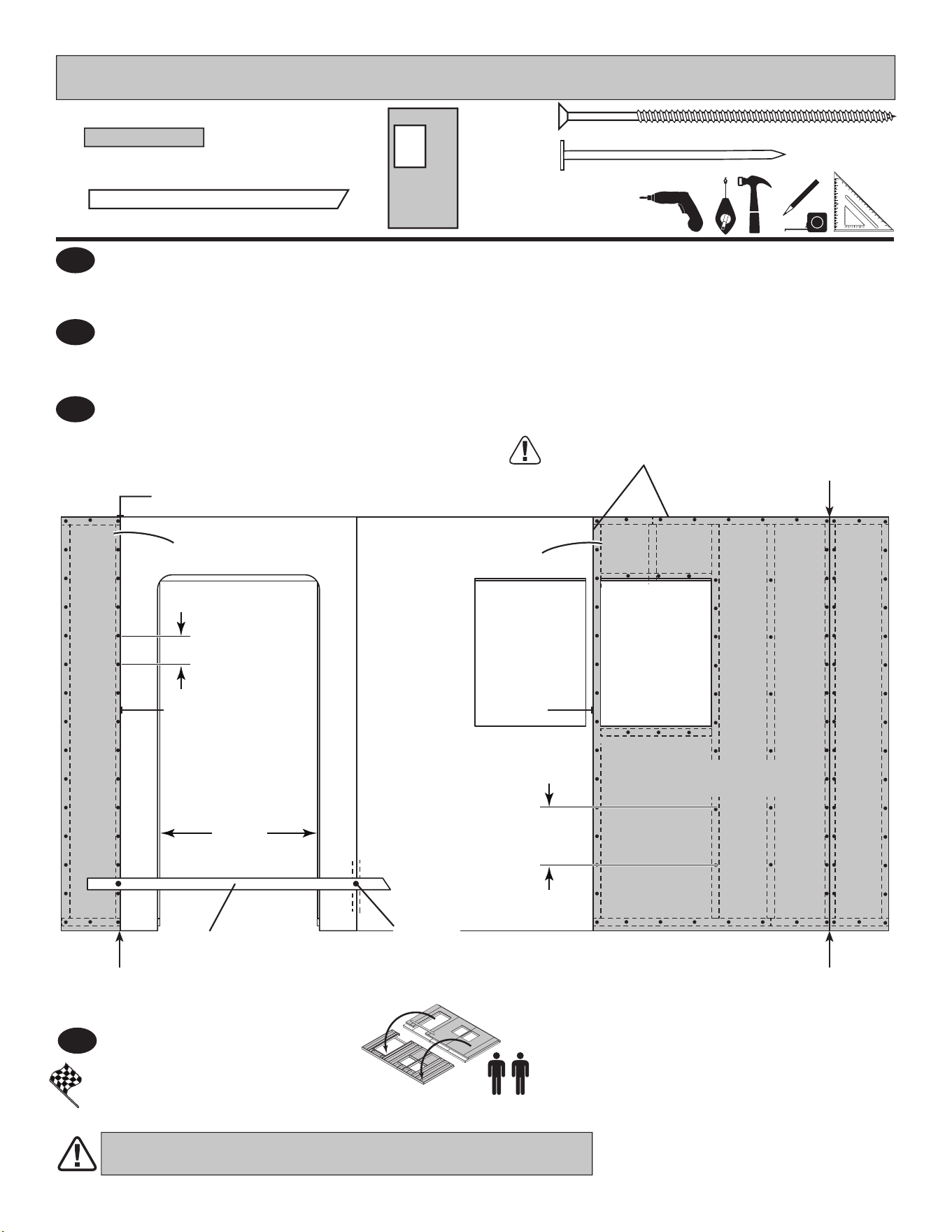
Secure using 2" nails 6" apart on edges.
Place right 48 x 84" panel ush to left panel with primed side up.
3
3-1/2"
(8,9 cm)
You have nished building your gable end wall.
FINISH
4
Carefully ip the gable wall over.
Remove temporary supports.
48 x 84"
(121,9 x 213,4 cm)
x1
Flush
Flush
6"
(15,2 cm)
3-1/2"
(8,9 cm)
48"
(121,9 cm)
Primed
side up
x16
2" (5,1 cm)
x13
1-1/2" (3,8 cm)
1-1/2"
(3,8 cm)
Nails
2" (5,1 cm)
Nails
2" (5,1 cm)
Nails
39
2" (5,1 cm)
PARTS REQUIRED
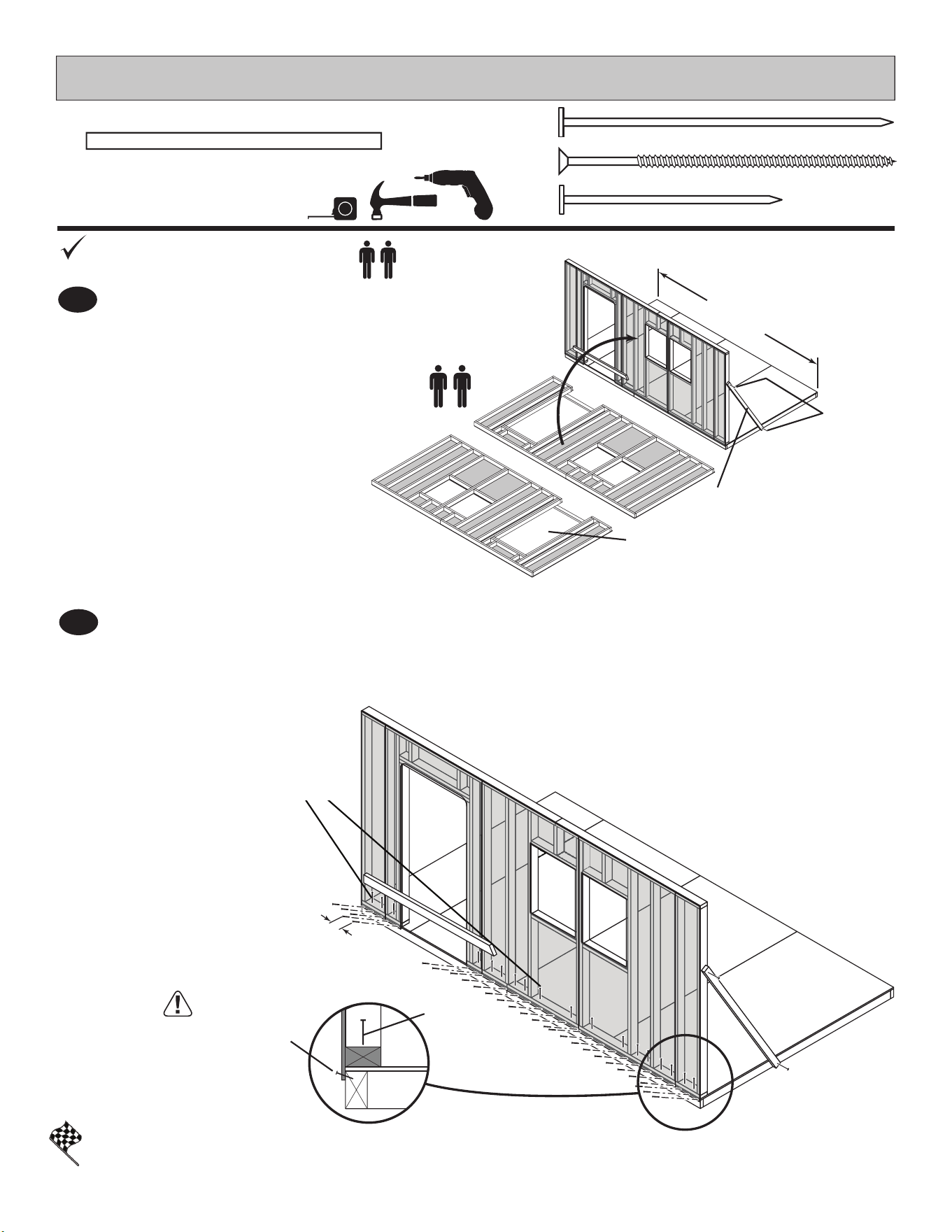
First, nail lower edge of panel to oor frame using 2" nails 6" apart.
Angle nail to hit oor frame (Fig. A).
Secure wall bottom plates to oor using 3" nails (Fig. A).
2
You have nished standing your front wall.
FINISH
3" (7,6 cm)
x18
3" (7,6 cm)
x2
x28
FRONT WALL
3" (7,6 cm) Nails
BEGIN
Stand front wall on oor.
Center wall on the 168" (426,7 cm) oor dimension.
Use
OO as a temporary brace. Secure with two 3" screws.
1
OO
x1
1-1/4 x 2-1/2 x 69" (3,2 x 6,3 x 175,3 cm)
3" (7,6 cm)
Screws
OO
168"
(426,7 cm)
DOOR
LOCATION
MAY VARY
Nail 2" nails rst.
2" (5,1 cm)
Nails
3" (7,6 cm)
Nails
Fig. A
6"
(15,2 cm)
Temporary Support
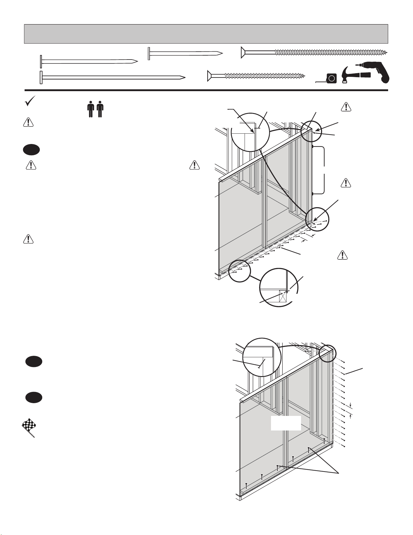
Set gable end wall on oor and secure top of wall
using one 2" screw into top plate (Fig A).
1
40
GABLE END WALL
3" (7,6 cm)
2" (5,1 cm)
x18
2" (5,1 cm)
x2
x1
x14
1-1/2" (3,8 cm)
PARTS REQUIRED:
3" (7,6 cm)
x6
It is important to secure the gable end wall
in the following order:
ENSURE TOP OF WALL FRAMES ARE FLUSH.
Nail lower edge of panels to oor using 2" nails 6" apart.
Angle nail to hit oor frame (Fig. B).
ENSURE GABLE AND FRONT WALL
PANELS ARE FLUSH BEFORE SECURING.
You have nished standing your gable end wall.
FINISH
Secure gable end wall to oor using 3" nails (Fig. C).
Nail gable end wall panel to front wall stud
using 1-1/2" nails 6" apart (Fig. C).
2
3
6"
(15,2 cm)
Flush
Fig. A
2" (5,1 cm)
Nails
Fig. B
2" (5,1 cm)
Nail
Angle nail to hit
oor frame.
Secure gable wall top frame 2 x 4 using one 3" screw
toe-screwed into front wall frame at an angle as
shown (Fig. D).
6"
(15,2 cm)
3" (7,6 cm)
Nails
1-1/2"
(3,8 cm)
Nails
Fig. D
3" (7,6 cm)
Screw
BEGIN
Stand wall on oor.
2" (3,8 cm)
Screw
2"
(5,1 cm)
Screw
Fig. C
Move to the bottom of gable end wall and
secure bottom of wall using one 2" screw into
front wall bottom plate (Fig A).
Flush
STEP 2 SECOND
SCREW
STEP 1 FIRST
SCREW
STEP 3
2"
(5,1 cm)
Screw
Flush
41
PARTS REQUIRED:
3" (7,6 cm)
x1
BACK WALL
2" (5,1 cm)
x2
x14
1-1/2" (3,8 cm)
Fig. A
Flush
STEP 3 FIRST
SCREW
BEGIN
Stand back wall on oor.
Center back wall on the 168" (426,7 cm) oor dimension.
Secure top of wall using one 2" screw into top plate (Fig A).
1
Nail gable wall panel to back wall stud
using 1-1/2" nails 6" apart (Fig. B).
ENSURE GABLE AND BACK WALL PANELS
ARE FLUSH BEFORE SECURING.
6" (15,2 cm)
Fig. B
1-1/2"
(3,8 cm)
Nails
Fig. C
3" (7,6 cm)
Screw
3" (7,6 cm)
Screw
BE SURE TOP OF WALL FRAMES ARE FLUSH.
2"
(7,6 cm)
Screw
2" (5,1 cm)
Screw
2
Move to the bottom of gable end wall and
secure bottom of wall using one 2" screw
into back wall bottom plate (Fig A).
Flush
Secure gable wall top frame 2 x 4 using one 3" screw
toe-screwed into back wall frame at an angle
as shown (Fig. C).
STEP 4 SECOND
SCREW
168"
(426,7 cm)
42
PARTS REQUIRED:
Nail lower edge of back wall panels to oor frame using 2" nails 6" apart.
Angle nail to hit oor frame (Fig. D).
3
Secure back wall bottom plates to oor using 3" nails (Fig. D).
Remove temporary supports.
3" (7,6 cm)
x14
2" (5,1 cm)
x30
BACK WALL
3" (7,6 cm)
Nails
You have nished standing your back wall.
FINISH
6"
(15,2 cm)
Nail 2" nails rst.
2" (5,1 cm)
Nails
3" (7,6 cm)
Nails
Fig. D
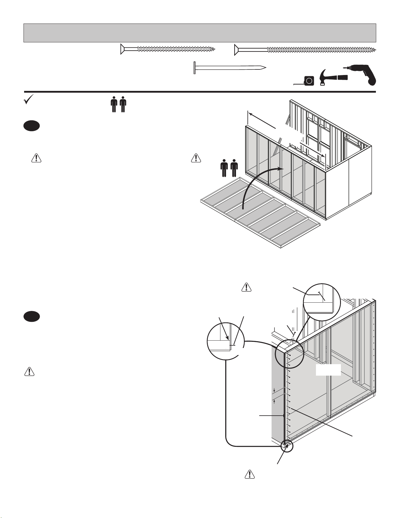
Set gable door wall on oor and secure using one 2" screw (Fig A).
1
ENSURE TOP WALL FRAMES ARE FLUSH.
2
43
3" (7,6 cm)
GABLE DOOR WALL
2" (5,1 cm)
x8
x2
x28
1-1/2" (3,8 cm)
PARTS REQUIRED:
3" (7,6 cm)
x4
2" (5,1 cm)
x4
BEGIN
Stand gable door wall on oor.
It is important to secure the front wall in the following order:
2"
(5,1 cm)
Screw
2"
(5,1 cm)
Screw
Flush
Flush
Flush
Flush
Move to the bottom of gable end wall and secure bottom of wall using one 2" screw
into front and back wall bottom plates (Fig B).
ENSURE WALL PANELS ARE FLUSH BEFORE SECURING.
Fig. B
2" (5,1 cm)
Screw
Fig. A
2" (5,1 cm)
Screw
Flush
44
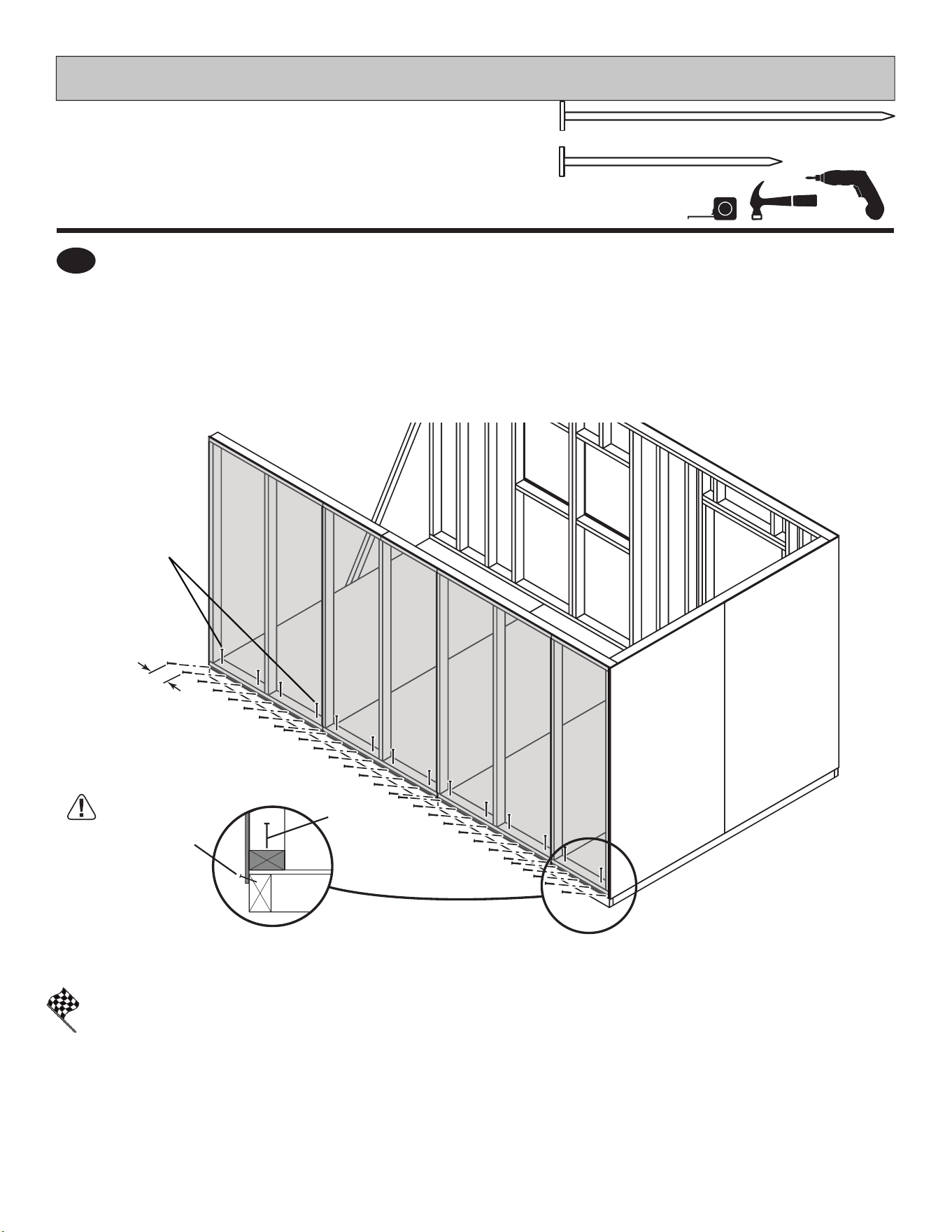
GABLE DOOR WALL
PARTS REQUIRED:
6"
(15,2 cm)
6"
(15,2 cm)
6"
(15,2 cm)
Fig. C
You have nished standing your gable door wall.
Nail gable wall panels to front and back wall
studs using 1-1/2" nails 6" apart (Fig. E).
Secure gable wall to oor using 3" nails
(Fig. E).
2"
(5,1 cm)
Nails
Angle nail
to hit oor
frame.
Fig. F
FINISH
4
3
5
6
3" (7,6 cm)
Screw
1-1/2"
(3,8 cm)
Nails
Fig. E
Secure gable door wall top frame 2 x 4 using
3" screws toe-screwed at each corner into top
wall frames at an angle as shown in (Fig. F).
3" (7,6 cm)
Nails
Nail lower edge of panels to oor using 2" nails 6" apart. Angle nail to hit oor frame (Fig. C).
Remove temporary support.
x16
1-1/2" (3,8 cm)
45
GABLE UNITS
PARTS REQUIRED:
x2 x2
Flush
Primed
side up
Primed
side up
2-9/16"
(6,5 cm)
1-3/4"
(4,4 cm)
1-3/4"
(4,4 cm)
1-1/2"
(3,8 cm)
Nails
1-1/2"
(3,8 cm)
Nails
PWA (on at)
AO
PVA (on at)
AO
Orient parts on at as shown. You will build TWO assemblies.
Place LEFT front gable panel as shown and secure using 1-1/2" nails as shown.
1
BEGIN
2
3
Place RIGHT front gable panel ush to left panel. Secure using 1-1/2" nails as shown.
Repeat Steps 1 - 2 to build second gable unit.
You have nished assembling your gable units.
FINISH
Flush
x2
2 x 4 x 10" (5,1 x 10,2 x 25,4 cm)
PWA
x2
2 x 4 x 6" (5,1 x 10,2 x 15,2 cm)
PVA
AO
x2
2 x 4 x 22-1/2" (5,1 x 10,2 x 57,1 cm)
TEMPORARY SUPPORT
46
GABLE UNITS
PARTS REQUIRED:
3" (7,6 cm)
x4
x2 Gable Units
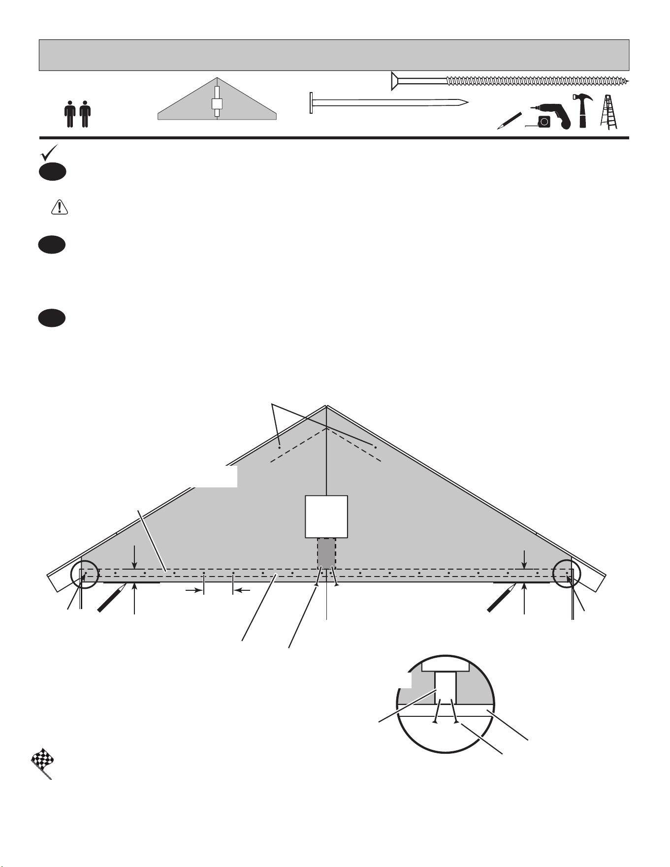
Set gable unit on top plate SZ. BE SURE GABLE UNIT IS CENTERED ON WALL BEFORE NAILING.
First, hold gable unit secure with one 2" nail on each side, then secure with two 2" nails
at top of gable panels into end rafter (Fig. A).
Continue nailing lower edge of panels into top plate using 2" nails 6" apart as shown
1
BEGIN
Install both gable units the same on both gable walls. Measure 2-9/16" down from top plate and mark
at each side as shown (Fig A).
You have nished installing your gable units.
FINISH
2" (5,1 cm)
x40
PVA
3"
(7,6 cm)
Screws
Fig. B
TOP PLATE (SZ)
SZ
3"
(7,6 cm)
Screws
NAIL FIRST
2" (5,1 cm)
NAIL FIRST
2" (5,1 cm)
2" (5,1 cm)
Nails
6"
(15,2 cm)
Fig. A
TOP PLATE
2-9/16"
(6,5 cm)
Measure and
Mark
2-9/16"
(6,5 cm)
Measure and
Mark
On the inside, secure gable unit with 3" screws toe-screwed into SZ at an angle as shown in (Fig. B).
2
3
47
GABLE WALL
Door to LEFT
Fig. A
BACK WALL
2nd Stud
3" (7,6 cm)
x2
x1
2 x 4 x 96" (5,1 x 10,2 x 243,8 cm)
TP
x1
2 x 3 x 96" (5,1 x 7,6 x 243,8 cm)
PT
PARTS REQUIRED:
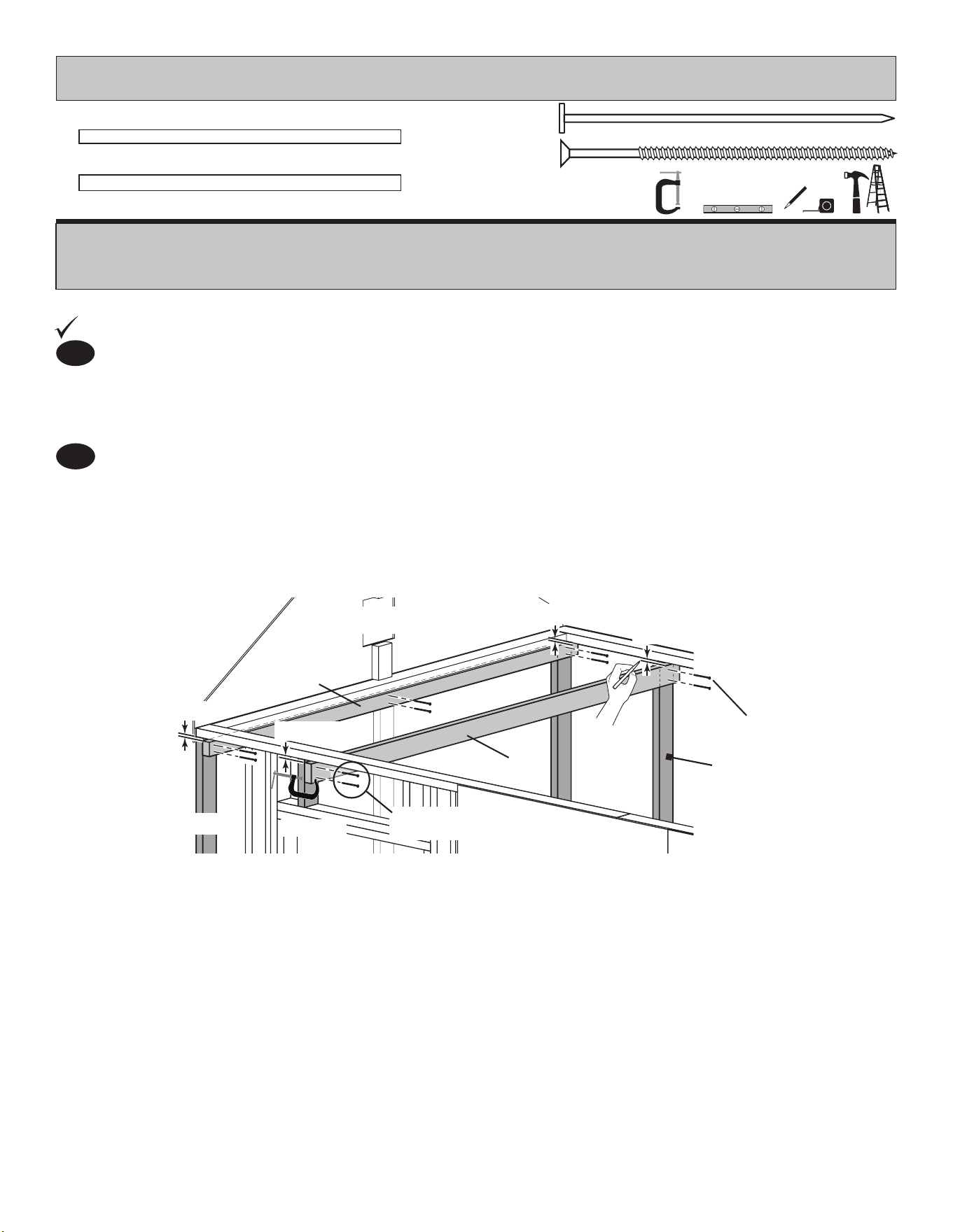
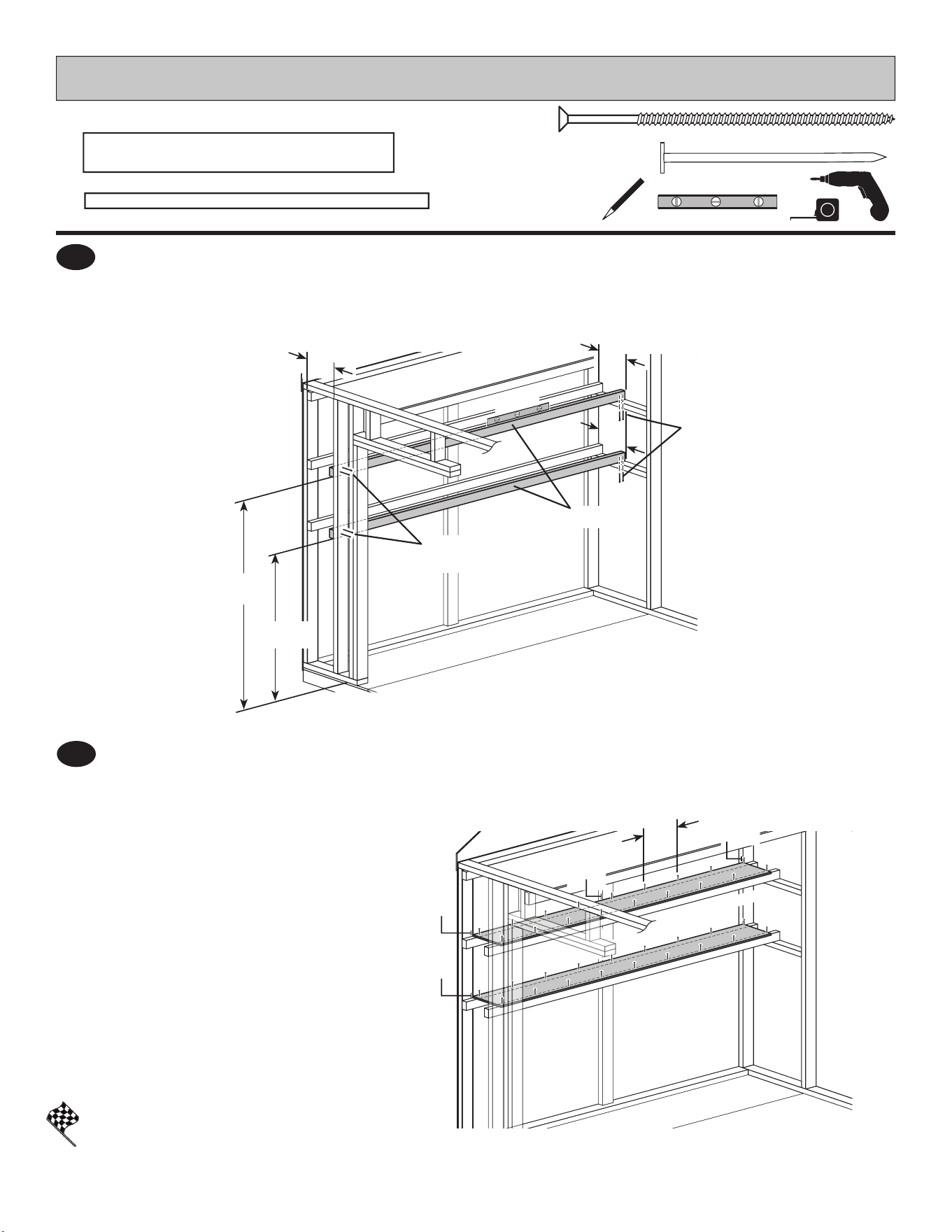
LOFT
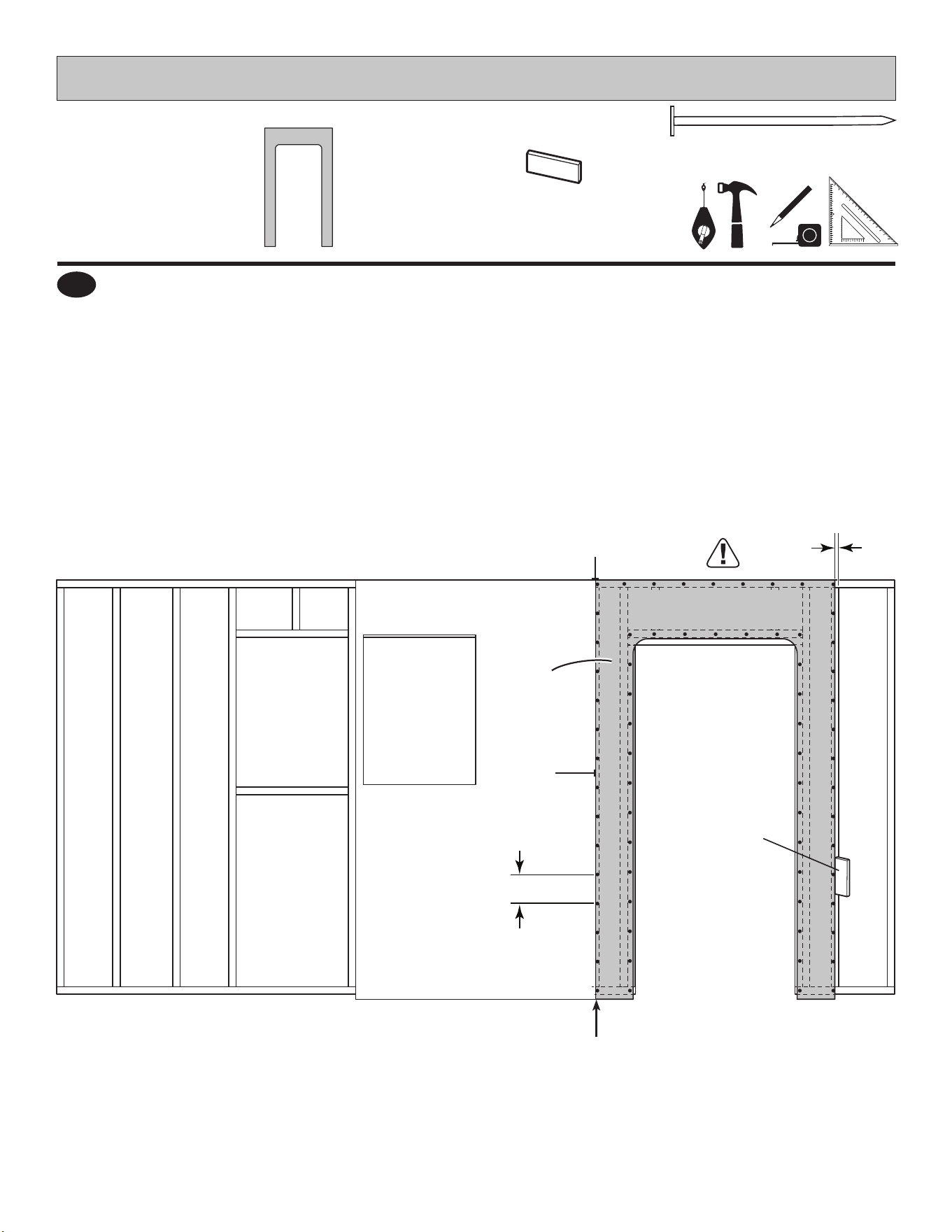
Measure and mark gable wall corner studs 1/2" down from top plates (Fig. A).
Place and hold top of PT on 1/2" marks. Secure PT with (6) 3" nails.
Measure and mark back wall 2nd stud and over-door crippler 1/2" down from top plates (Fig. A).
Place and hold top of TP on 1/2" marks. Secure TP with 3" nails and 3" screws into over-door crippler.
2
BEGIN
1
3" (7,6 cm)
x8
TP
PT
1/2" (13 mm)
1/2" (13 mm)
1/2" (13 mm)
1/2" (13 mm)
3"
(7,6 cm) Nails
If your front wall has door to LEFT side, see Fig. A.
If your front wall has door to RIGHT side, see next page.
3"
(7,6 cm) Screws
CLAMP
48
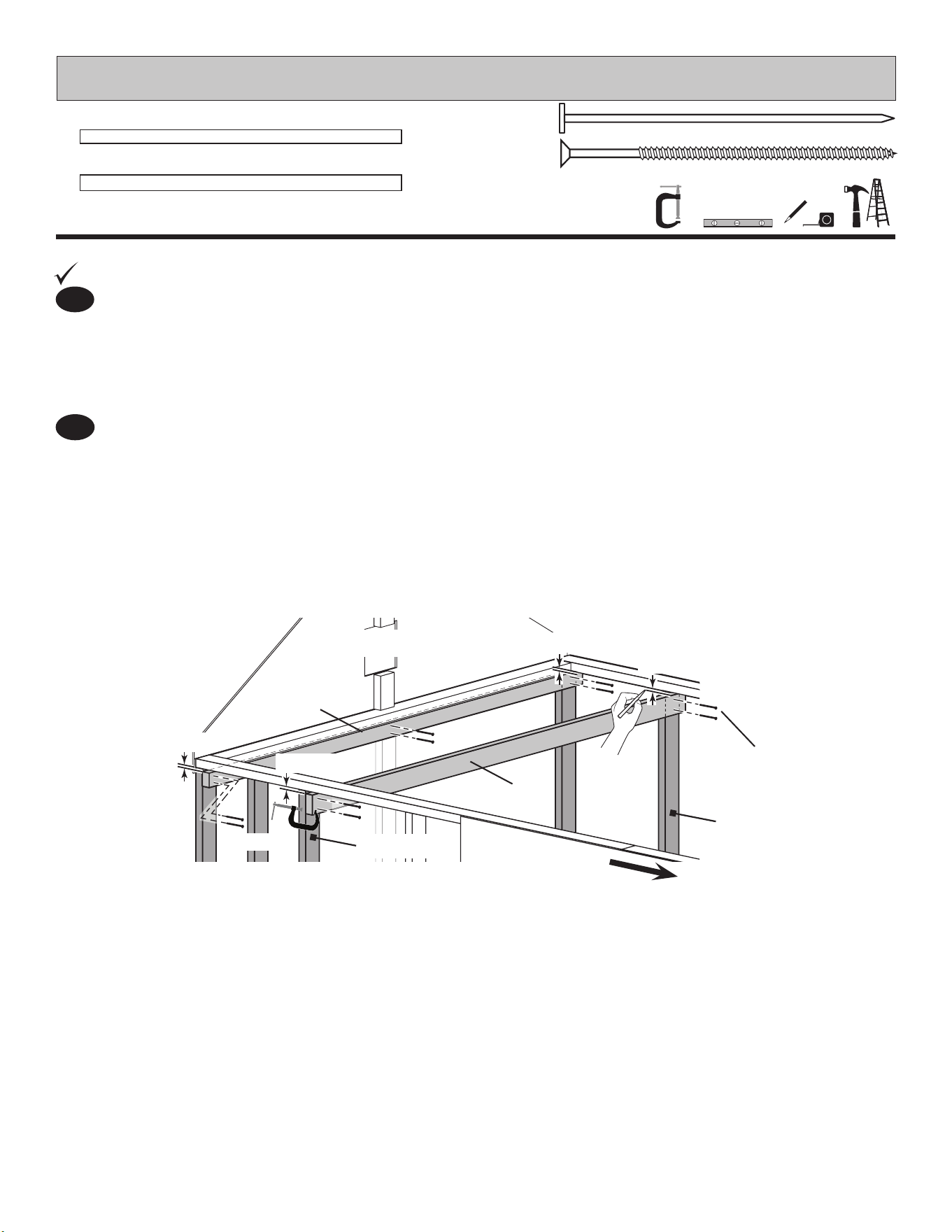
Door to RIGHT
Fig. B
GABLE WALL
BACK WALL
2nd Stud
3rd Stud
3" (7,6 cm)
x2
x1
2 x 4 x 96" (5,1 x 10,2 x 243,8 cm)
TP
x1
2 x 3 x 96" (5,1 x 7,6 x 243,8 cm)
PT
PARTS REQUIRED:
LOFT
3" (7,6 cm)
x8
Measure and mark gable wall corner studs 1/2" down from top plates (Fig. B).
Place and hold top of PT on 1/2" marks. Secure PT with (6) 3" nails.
Measure and mark TP 1/2" down from top plates at back wall 2nd stud.
Measure and mark TP 1/2" down from top plates at front wall 3rd stud.
Place and hold top of TP on 1/2" marks. Secure TP with 3" nails.
2
BEGIN
1
TP
PT
1/2" (13 mm)
1/2" (13 mm)
1/2" (13 mm)
1/2" (13 mm)
3"
(7,6 cm) Nails
CLAMP
49
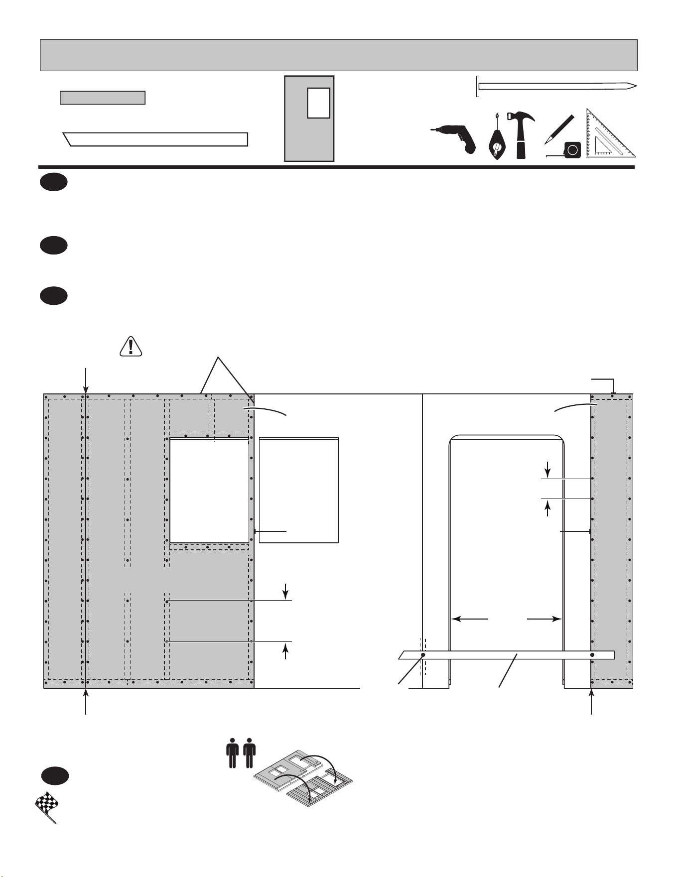
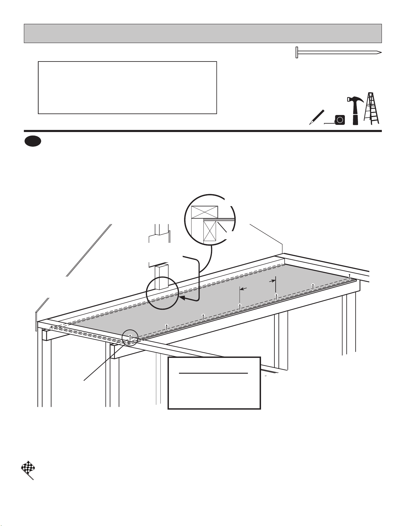
x1
7/16 x 26-5/8 x 89" (1,1 x 67,6 x 226,1 cm)
7/16 x 26-5/8 x 89"
PARTS REQUIRED:
2" (5,1 cm)
x7
LOFT
FINISH
3
You have nished installing your loft.
Place 7/16" x 26-5/8" x 89" loft panel centered on loft supports.
Slide panel into gap at gable wall (Fig. D).
Secure to loft frame using 2" nails evenly spaced.
Fig. C
2" (5,1 cm)
Nails
ATTENTION:
LOAD NOT TO EXEED
250 lbs (113,4 kg)
EVENLY DISTRIBUTED
ACROSS LOFT
FIT LOFT PANEL INTO
1/2" GAP
Approximately
15"
(38,1 cm)
Fig. D
Gap
50
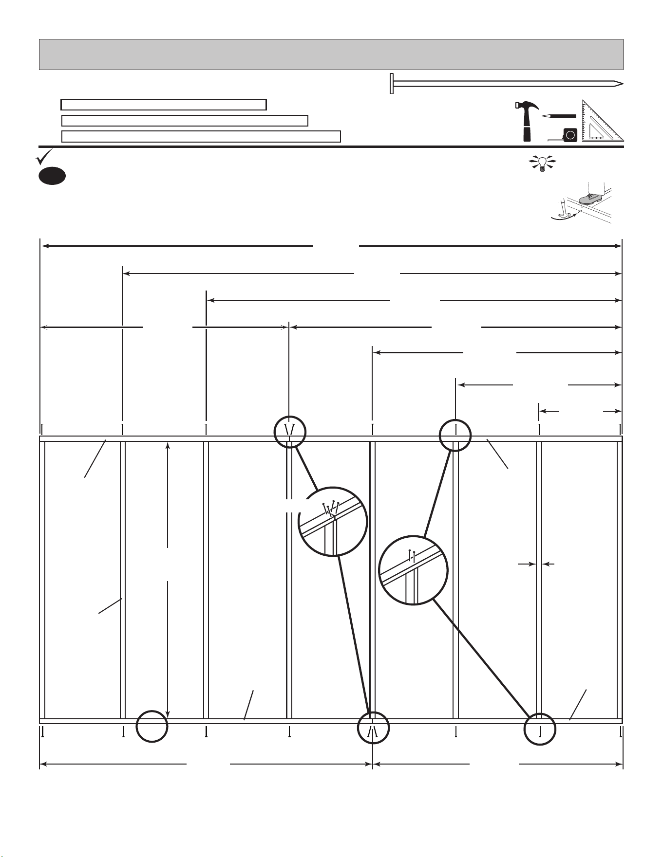
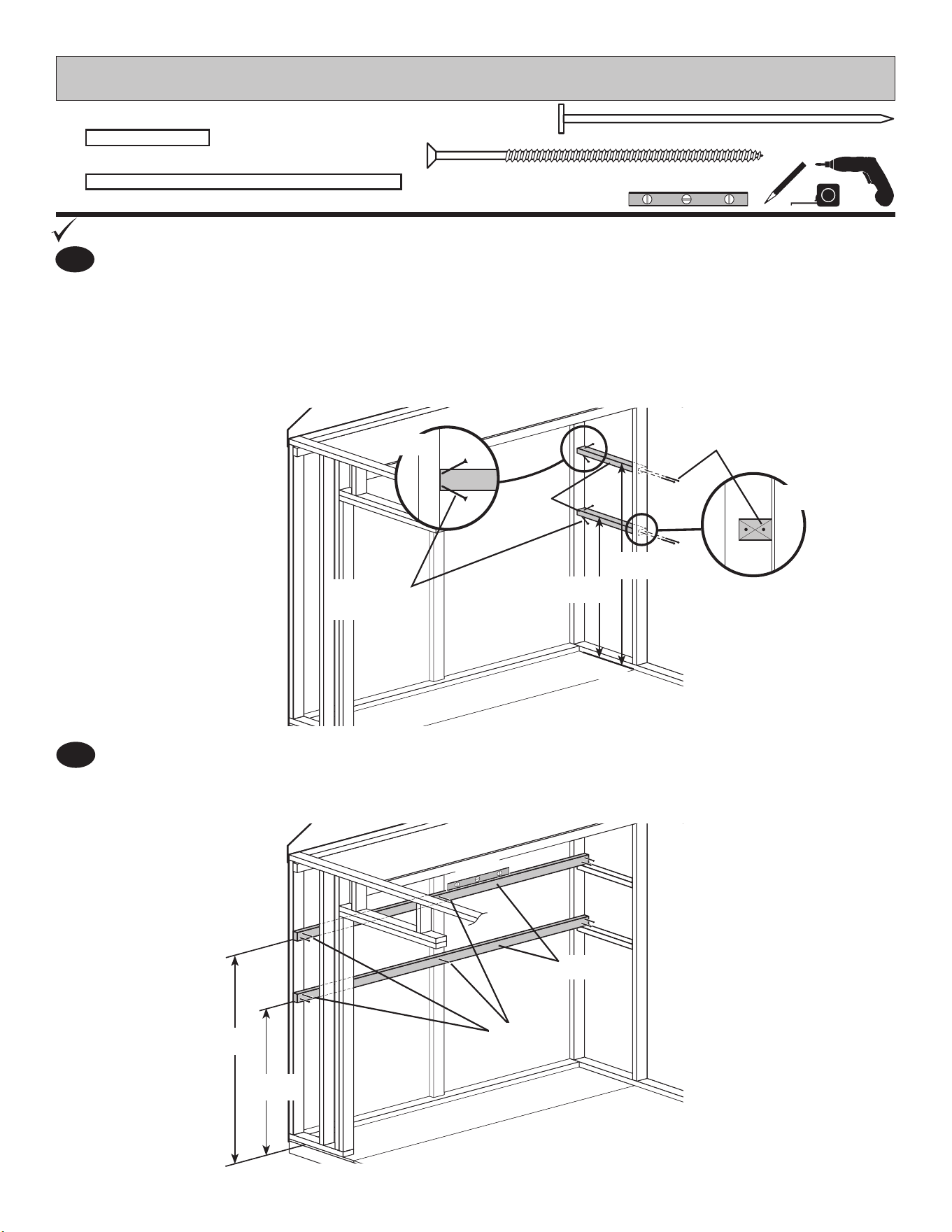
1
BEGIN
x2
2 x 3 x 21-3/4" (5,1 x 7,6 x 55,2 cm)
AED
SHELVES
2 x 3 x 96" (5,1 x 7,6 x 243,8 cm)
x2
PT
PT
AED
58-1/2"
(148,6 cm)
40-1/2"
(102,9 cm)
3" (7,6 cm)
x4
3" (7,6 cm)
Screws
PARTS REQUIRED:
2
FLOOR
Secure each AED using (2) 3" screws toe-screwed at an angle at gable wall stud
and 3" nails into eave wall stud as shown.
Place loft support ledger boards AED between gable wall and eave wall stud with
narrow side to wall panel (Fig. A).
Secure both PT using 3" nails as shown.
Measure and mark location for AED (Fig. A, Fig. B).
Mark locatins for both PT shelf supports.
LEVEL
3" (7,6 cm)
Nails
58-1/2"
(148,6 cm)
40-1/2"
(102,9 cm)
3" (7,6 cm)
x10
Fig. A
Fig. B
3" (7,6 cm)
Nails
51
x2
7/16 x 10-1/2 x 89" (1,1 x 26,7 x 226,1 cm)
2 x 3 x 96" (5,1 x 7,6 x 243,8 cm)
x2
PT
SHELVES
FINISH
You have nished installign your shelves.
58-1/2"
(148,6 cm)
40-1/2"
(102,9 cm)
3" (7,6 cm)
Screws
3" (7,6 cm)
Screws
3" (7,6 cm)
x8
PT
PARTS REQUIRED:
4
Place upper and lower 7/16" x 10-1/2" x 89" shelf panels centered on PT shelf supports.
Ensure panel is ush to gable wall studs.
Secure each shelf with (18) 2" nails spaced evenly.
LEVEL
2" (5 cm)
x36
3
Secure PT's using 3" screws at locations shown.
Measure and mark both AED's at the measurements shown from gable wall studs.
Mark front wall stud at the dimensions shown
9-1/2"
(24,1 cm)
9-1/2"
(24,1 cm)
Approximately
11" (27,9 cm)
Flush
Flush
Flush
Flush
7/16 x 10-1/2 x 89"
7/16 x 10-1/2 x 89"
52
3" (7,6 cm)
PARTS REQUIRED:
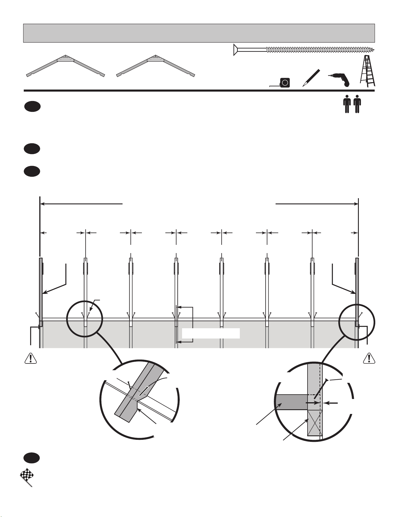
RAFTERS
x28
Align over studs.
24"
(61 cm)
24"
(61 cm)
24"
(61 cm)
24"
(61 cm)
24"
(61 cm)
24-3/8"
(61,9) cm)
24-3/8"
(61,9) cm)
MEASUREMENTS ARE TO CENTER OF RAFTER
FLUSH WITH OUTSIDE OF WALL PANEL
x6
Pre-Assembled Rafter
with 2 gussets
x2
Pre-Assembled Rafter
with 1 gusset
FINISH
Place remaining 2 gusset rafters on top plate, aligned over studs as shown and secure with 3" screws
(Fig. B).
Locate and secure both 1 gusset rafters 3/8" over top plate with one 3" screw above notch (Fig. C).
NOTE: Gussets face inside of shed.
Secure rafter to top plate with two 3" screws above notch (Fig. B).
You have nished installing your rafters.
3
BEGIN
¸
1
Locate rst 2 gusset rafter on top plate, aligned over studs at each side and tight to side wall
(Fig. A, Fig. B).
2
Repeat Steps 1 - 3 to secure rafters to opposite side top plate.
4
BEGIN
HERE
Fig. A
Flush
Flush
1 Gusset
Rafter
1 Gusset
Rafter
Fig. B
Tight to
side wall
(3) 3" (7,6 cm)
Screws
Fig. C
3" (7,6 cm)
Screw
1 Gusset
Rafter
Top Plate
3/8"
(10 mm)
53
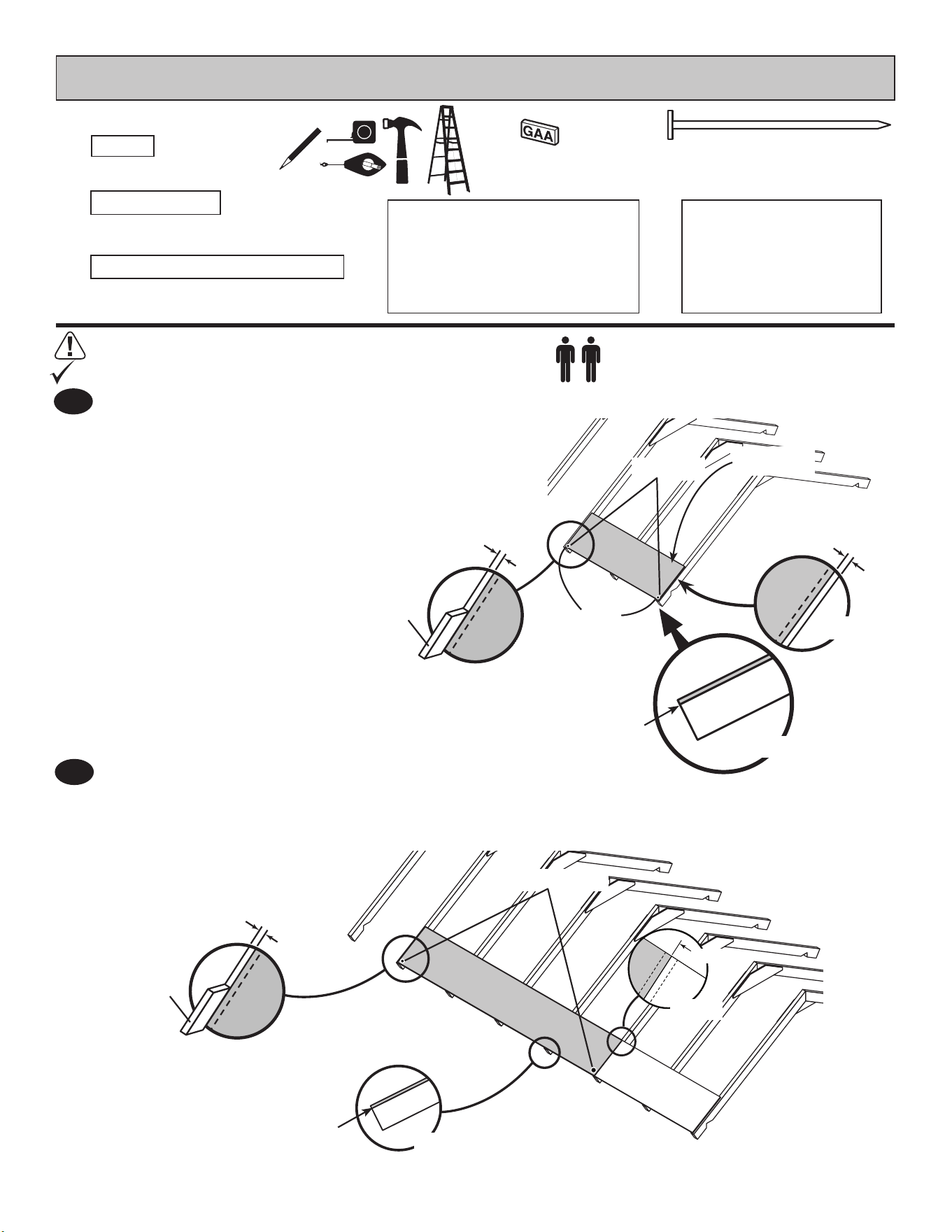
Roof panels may cause serious injury until securely fastened.
1
BEGIN
2" (5,1 cm)
PARTS REQUIRED:
ROOF PANELS
x174
3/4" GAUGE
BLOCK
Attach the 15-7/8" x 48" panel with the rough side up (painted-grid lines side)
with a 3/4" (1,9 cm) measurement on the rafter (Fig A).
The panel is ush at the gable end overhang (Fig. B),
and the panel is 1/2" from the end rafter (Fig. C).
Secure panel with two 2" (5,1 cm) nails in the corners.
2
Attach a 15-7/8" x 96" roof panel with the rough side up with a
3/4" (1,9 cm) measurement on the rafter (Fig A) and ush with
the installed panel (Fig. C).
Secure panel with two 2" (5,1 cm) nails in the corners.
Flush
3/4"
(1,9 cm)
Gauge
Block
Fig. A
Fig. C
15-7/8" x 48"
Two Nails
Flush
at rafter ends.
Fig. B
Two Nails
Flush
at rafter ends.
Fig. B
3/4"
(1,9 cm)
Gauge
Block
Fig. A
Flush
Fig. C
15-7/8" x 96"
1/2"
(1,3 cm)
7/16 x 15-7/8 x 23-7/8"
(1,1 x 40,3 x 60,6 cm)
x2
7/16 x 15-7/8 x 96"
(1,1 x 40,3 x 243,8 cm)
x2
7/16 x 15-7/8 x 48"
(1,1 x 40,3 x 121,9 cm)
x2
7/16 x 48 x 96"
(1,1 x 121,9 x 243,8 cm)
x2
7/16 x 48 x 71-7/8"
(1,1 x 121,9 x 182,6 cm)
x2
54
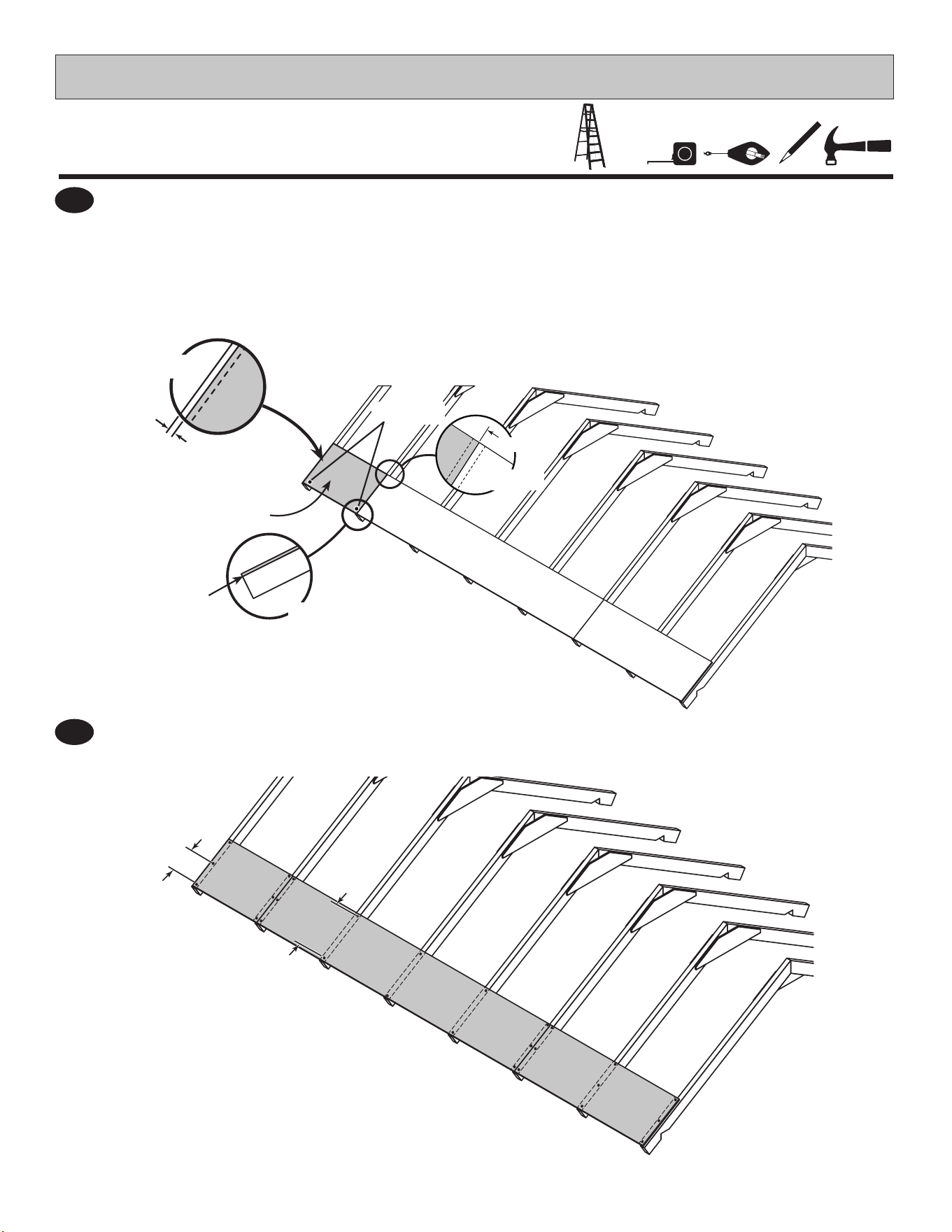
3
4
Secure the roof panels using 2" nails 6" apart on edges and 12" apart inside panel.
PARTS REQUIRED:
ROOF PANELS
6"
(15,2 cm)
12"
(30,5 cm)
Attach a 15-7/8" x 23-7/8" panel with the rough side up (painted-grid lines side),
ush with the installed 15-7/8" x 96" panel (Fig A).
The panel is ush at the gable end overhang (Fig. B),
and the panel is 1/2" from outside of the end rafter (Fig. C).
Secure panel with two 2" (5,1 cm) nails in the corners.
Flush
at rafter ends.
Fig. B
15-7/8" x 23-7/8"
Flush
Fig. A
Two Nails
Fig. C
1/2"
(1,3 cm)

55
PARTS REQUIRED:
ROOF PANELS
NOTE: Measurement from outside of wall panelNOTE: Measurement from outside of wall rafter
24-3/8"
(61,9) cm)
24"
(61 cm)
24"
(61 cm)
24"
(61 cm)
24"
(61 cm)
24"
(61 cm)
1/2"
(1,3 cm)
GAP
Fig. B
Fig. E
Flush
2" Nails
Fig. C
Place a 48" x 96" upper roof
panel with the rough side up and
ush to lower panels.
Ensure 1/2" gap at gable end rafter
(Fig. B) and 3/4" measurement on
the rafter (Fig. A).
Secure the lower edge of roof
panel using two 2" nails in corners
as shown.
Move up to the top of the panel
and keep spacing between the
center of the rafters (Fig. C).
Secure with one 2" nail into each
rafter (Fig. C).
Place a 48" x 71-7/8" upper
roof panel, rough side up and
ush with the installed
48" x 96" panel (Fig. D).
Ensure 1/2" gap at gable end
rafter (Fig. E).
Secure the lower edge of roof
panel using two 2" nails in
corners as shown.
Move up to the top of the panel
and keep spacing between the
center of the rafters (Fig. C).
Secure with one 2" nail into
each rafter (Fig. C).
5
6
Flush
Fig. D
3/4"
(1,9 cm)
Gauge
Block
Fig. A
Two Nails
NAIL
FIRST
Flush
Two Nails
NAIL
FIRST
48 x 96"
48 x 71-7/8"
1/2"
(1,3 cm)
G A P
24-3/8"
(61,9) cm)
56
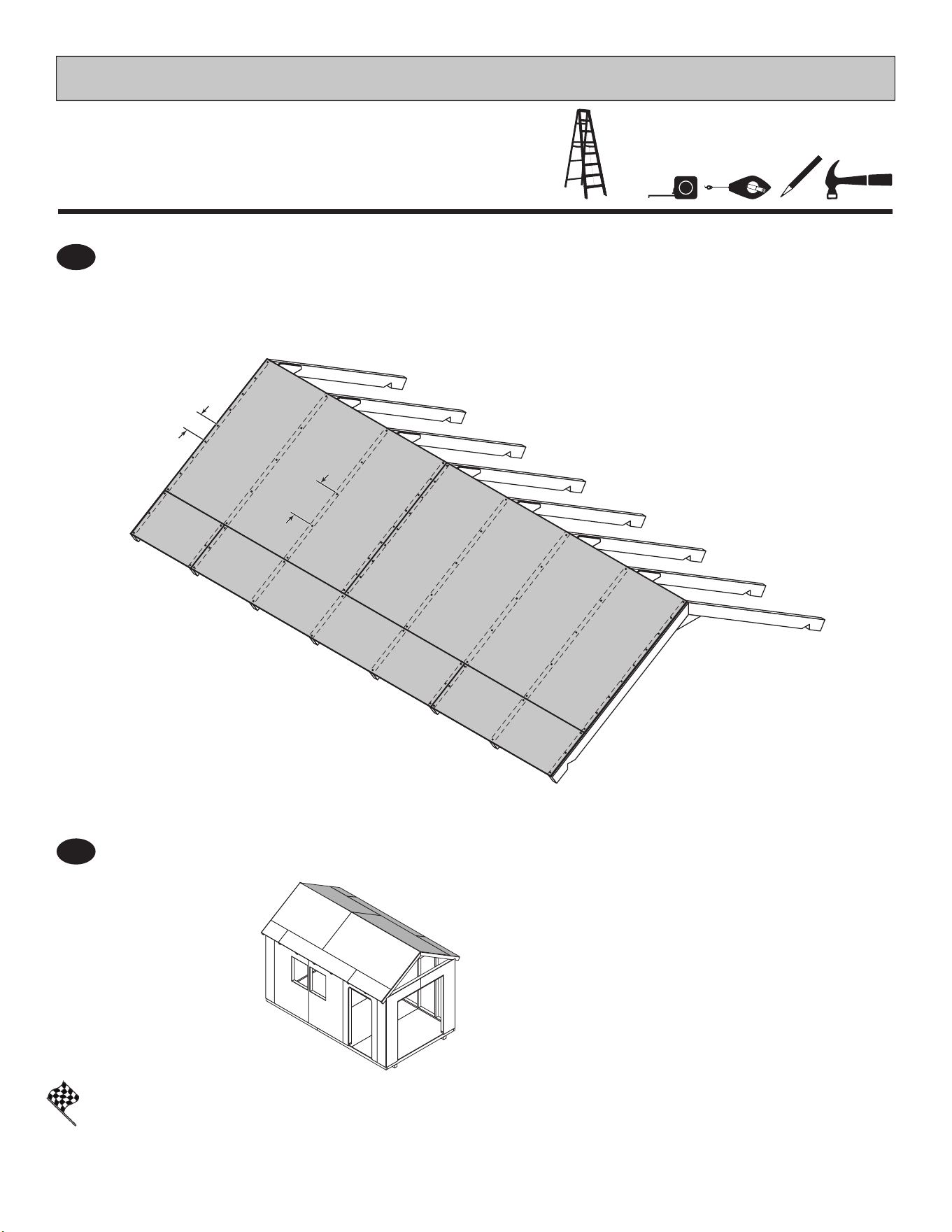
Nail the roof panels using 2" nails 6" apart on edges and 12" apart inside panel.
You have nished installing your roof panels.
Repeat process to attach roof panels on the opposite side.
8
PARTS REQUIRED:
ROOF PANELS
FINISH
6"
(15,2 cm)
12"
(30,5 cm)
7
57
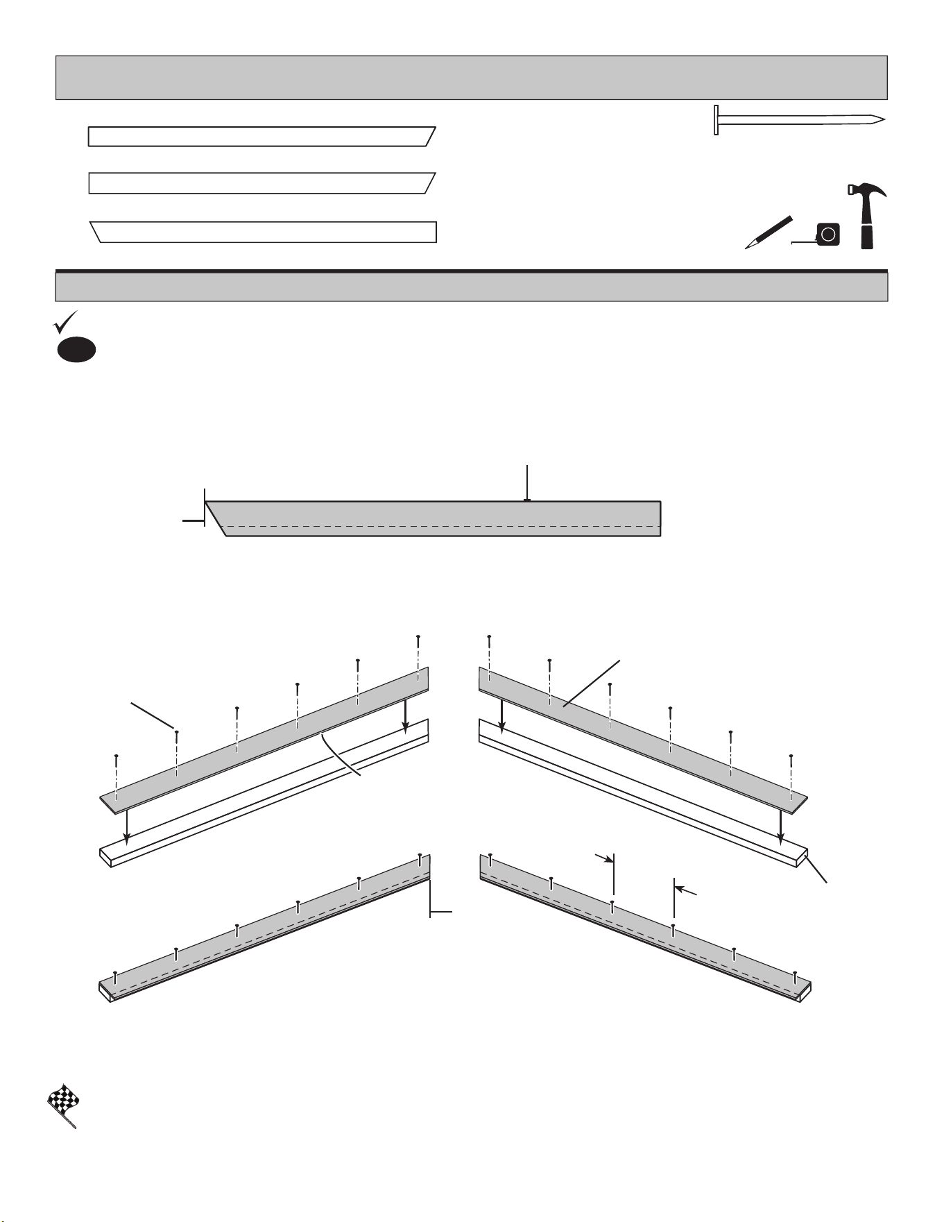
PARTS REQUIRED:
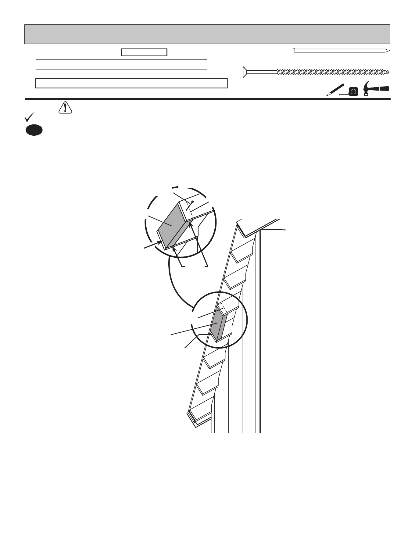
You have nished your gable trim units.
FINISH
GABLE TRIM
x2
3/8 x 4-3/4 x 64-1/8" (1 x 12,1 x 162,9 cm)
x2
3/8 x 4-3/4 x 64-1/8" (1 x 12,1 x 162,9 cm)
x4
2 x 4 x 64-1/8" (5,1 x 10,2 x 162,9 cm)
ATA
ATA
1-1/2"
(3,8 cm)
Nails
3/8" x 4-3/4" x 64-1/8"
(x2 Left & x2 Right)
Primed Side Down
Flush
Flush
Approximately
12"
(30,5 cm)
Flush
BEGIN
1
Secure with 1-1/2" nails spaced evenly (approximately 12" (30,5 cm).
Orient parts on oor. Line up 3/8" x 4-3/4" x 64-1/8" trim primed side down on top of ATA. Trim is
ush with ATA at end and along edges as shown (Fig. A).
x24
1-1/2" (3,8 cm)
You will build two LEFT and two RIGHT gable trim units.
Fig. A
LEFT
RIGHT
Primed side
down
58
PARTS REQUIRED:
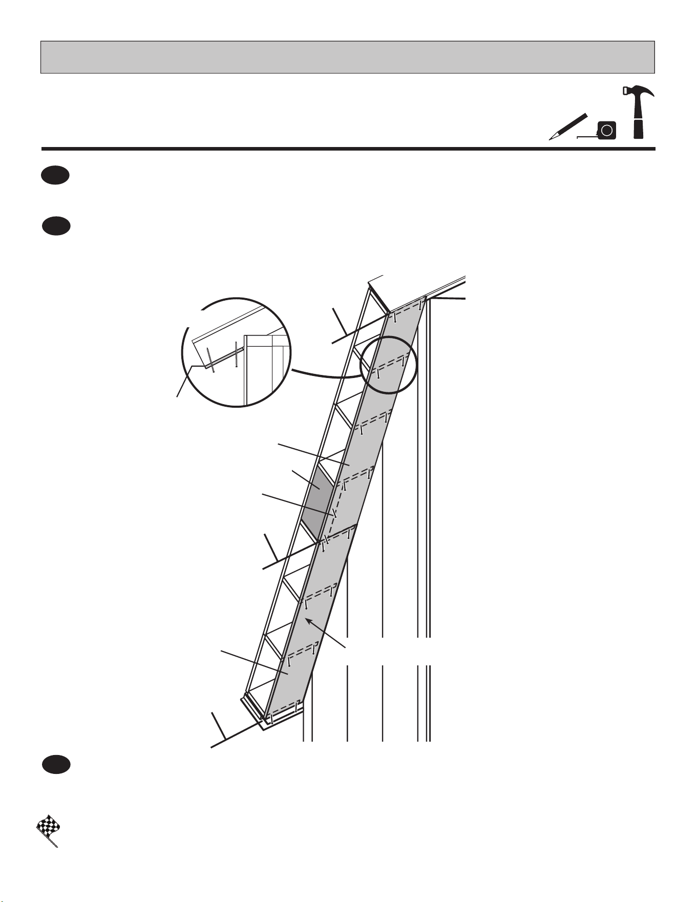
GABLE TRIM
3" (7,6 cm)
x2
RIGHT gable trim unit
LEFT GABLE TRIM UNIT
Flush
Flush
Flush
Flush
3" (7,6 cm)
Screws
3" (7,6 cm)
Screws
Flush at
Seam
RIGHT GABLE TRIM UNIT
x2
LEFT gable trim unit
24"
(61 cm)
Approximately
x16
Flush
Fig. B
You have nished installing your gable trim units.
FINISH
BEGIN
1
Secure with 3" screws into end rafter and spaced evenly (approximately 24" (61 cm).
Secure with 3" screws into end rafter and spaced evenly (approximately 24" (61 cm).
Repeat Steps 1 - 2 for opposite side.
Line up RIGHT gable trim unit ush to gable panel center seam and ush with roof sheathing
(Fig. A, Fig. B).
Line up LEFT gable trim unit ush to RIGHT gable trim unit and ush with roof sheathing
(Fig. A, Fig. B). Check gable trim units are ush at peak.
3
2
3" (7,6 cm)
Screws
Flush
Fig. A
End View
Flush at Peak
59
PARTS REQUIRED:
GABLE TRIM
Flush
Flush
Flush
Flush
2" (7,6 cm)
Finish Nails
2" (7,6 cm)
Finish Nails
RIGHT FASCIA
FASCIA
LEFT FASCIA
x4
3/8 x 4-3/4 x 54-5/8" (1 x 12,1 x 138,7 cm)
x2
3/8 x 10 x 17"
(1 x 25,4 x 43,2 cm)
Keystone
Flush
Flush
18"
(46 cm)
Approximately
You have nished installing your gable fascia and keystone.
FINISH
BEGIN
1
Secure with 2" nish nails into gable unit in pattern shown.
Secure with 2" nish nails into gable unit and spaced evenly (approximately 18" (46 cm).
Secure with 2" nish nails into gable unit and spaced evenly (approximately 18" (20,3 cm).
Repeat Steps 1 - 3 for opposite side.
Line up (10" x 17") Keystone ush to gable unit peak and ush with roof sheathing (Fig. A).
Place fascia 4-3/4" x 54-5/8" ush to Keystone and ush with roof sheathing (Fig. B).
Place LEFT fascia ush to Keystone and ush with roof sheathing (Fig. B).
4
2
3
2" (5,1 cm)
Finish Nail
Flush
Fig. B
End
View
x48
2" (5,1 cm)
Fig. A
Flush
Flush
Keystone
60
PARTS REQUIRED:
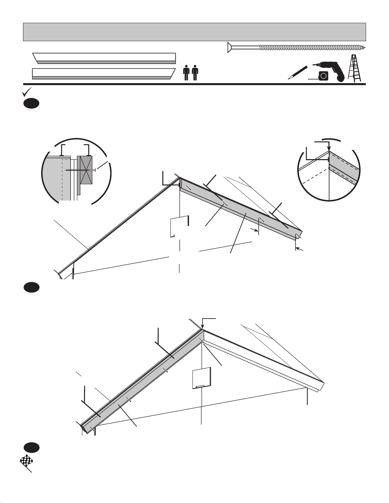
EAVE SIDE SOFFITS
Ensure soft boards are ush at rafter ends (Fig. B) and ush at seam.
x36
2" (5,1 cm)
1
BEGIN
x2
3/8 x 4-7/8 x 73-1/2" (1 x 12,4 x 186,7 cm)
x2
3/8 x 4-7/8 x 96" (1 x 12,4 x 243,8 cm)
Flush
x2
2 x 4 x 22-1/2" (5,1 x 10,2 x 57,1 cm)
AO
Place eave nailer AO between two center rafters as shown.
Keep AO ush to the outside edge of rafter (Fig. A, Fig. B).
Pre-drill a 1/8" hole through center rafters into AO to avoid splitting rafter. Secure with 3" screws (Fig. A).
AO
AO
Fig. A
PRE-DRILL
Flush
Flush
(2) 3" (7,6 cm) Screws
(2) 3" (7,6 cm) Screws
3" (7,6 cm)
x4
61
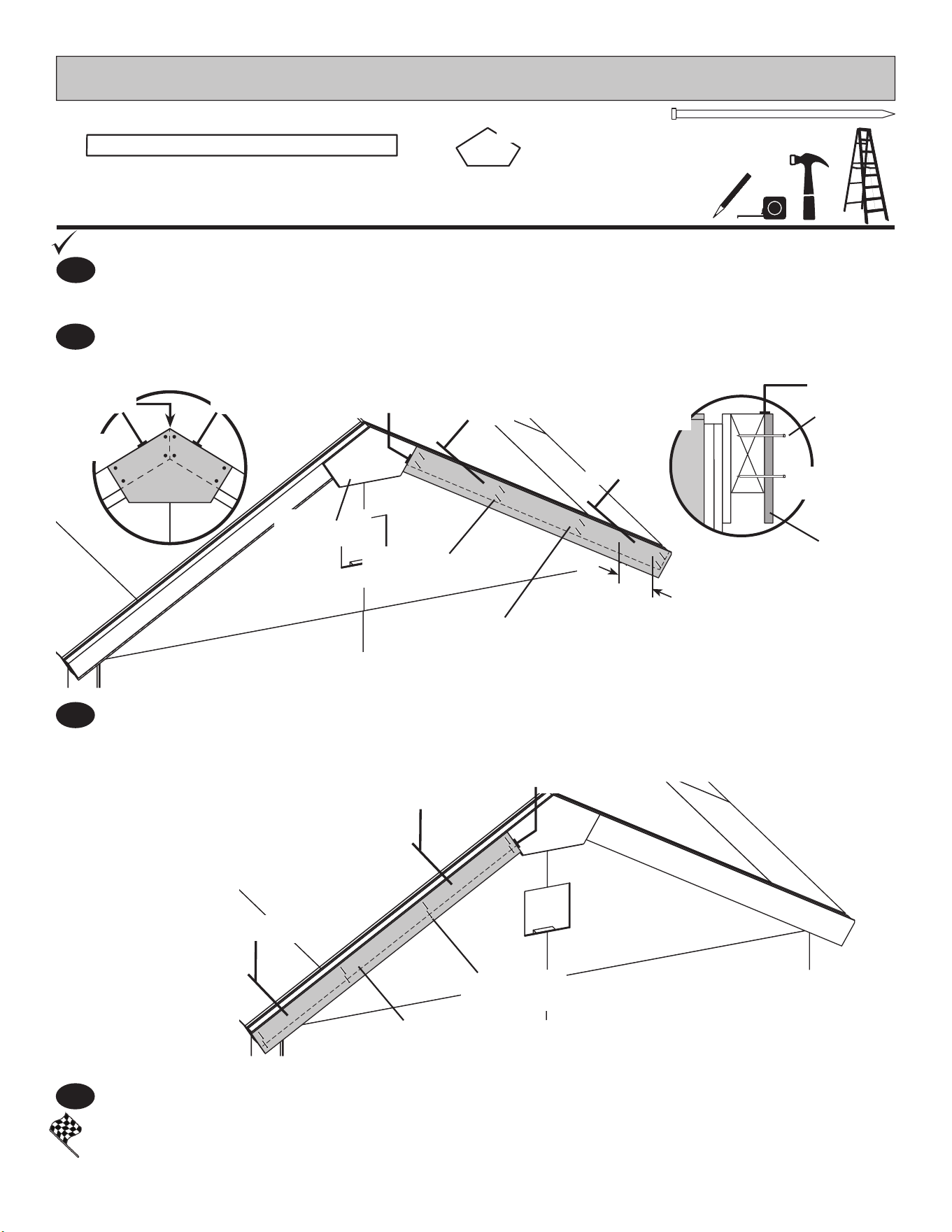
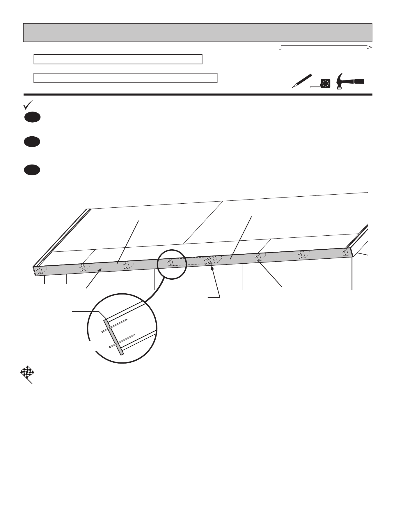
PARTS REQUIRED:
EAVE SIDE SOFFITS
Place 96" sof t board primed side down, ush to gable trim unit and rafter ends (Fig B).
Secure using 2" nish nails, two in each rafter and two into edge of AO as shown.
Position 73-1/2" sof t board primed side down ush to gable trim unit and rafter ends (Fig B).
Secure using 2" nish nails, two in each rafter.
Repeat Steps 1 - 3 to attach eave nailer and sof t boards on the opposite side.
4
2
3
You have nished installing your eave nailer and sof t boards.
FINISH
Primed Side Down
2" (5,1 cm)
Finish Nails
Flush to
gable trim
unit
Flush to
gable trim
unit
Flush at
seam
4-7/8" x 73-1/2"
4-3/4" x 96"
AO
Flush
Fig. B
62
EAVE SIDE FASCIA
x36
2" (5,1 cm)
Repeat Steps 1 - 2 to attach eave nailer and sof t boards on the opposite side.
1
BEGIN
3
2
You have nished installing your eave side fascia.
FINISH
PARTS REQUIRED:
Primed Side Out
2" (5,1 cm) Finish Nails
Flush with
roof panel
Fig.A
Flush
x2
3/8 x 4-3/4 x 77-1/4" (1 x 12,1 x 196,2 cm)
x2
3/8 x 4-3/4 x 96" (1 x 12,1 x 243,8 cm)
Place 77-1/4" sof t board primed side down, ush to gable trim unit and roof sheathing (Fig A).
Secure using 2" nish nails, two in each rafter and two into face of AO as shown.
Place 96" sof t board primed side down,
ush to gable trim unit and roof sheathing (Fig A). Secure
using 2" nish nails, two in each rafter and two into face of AO as shown.
4-3/4" x 77-1/4"
4-3/4" x 96"
1 x 3 x 5" (2,5 x 7,6 x 12,7 cm)
x1
GAA
63
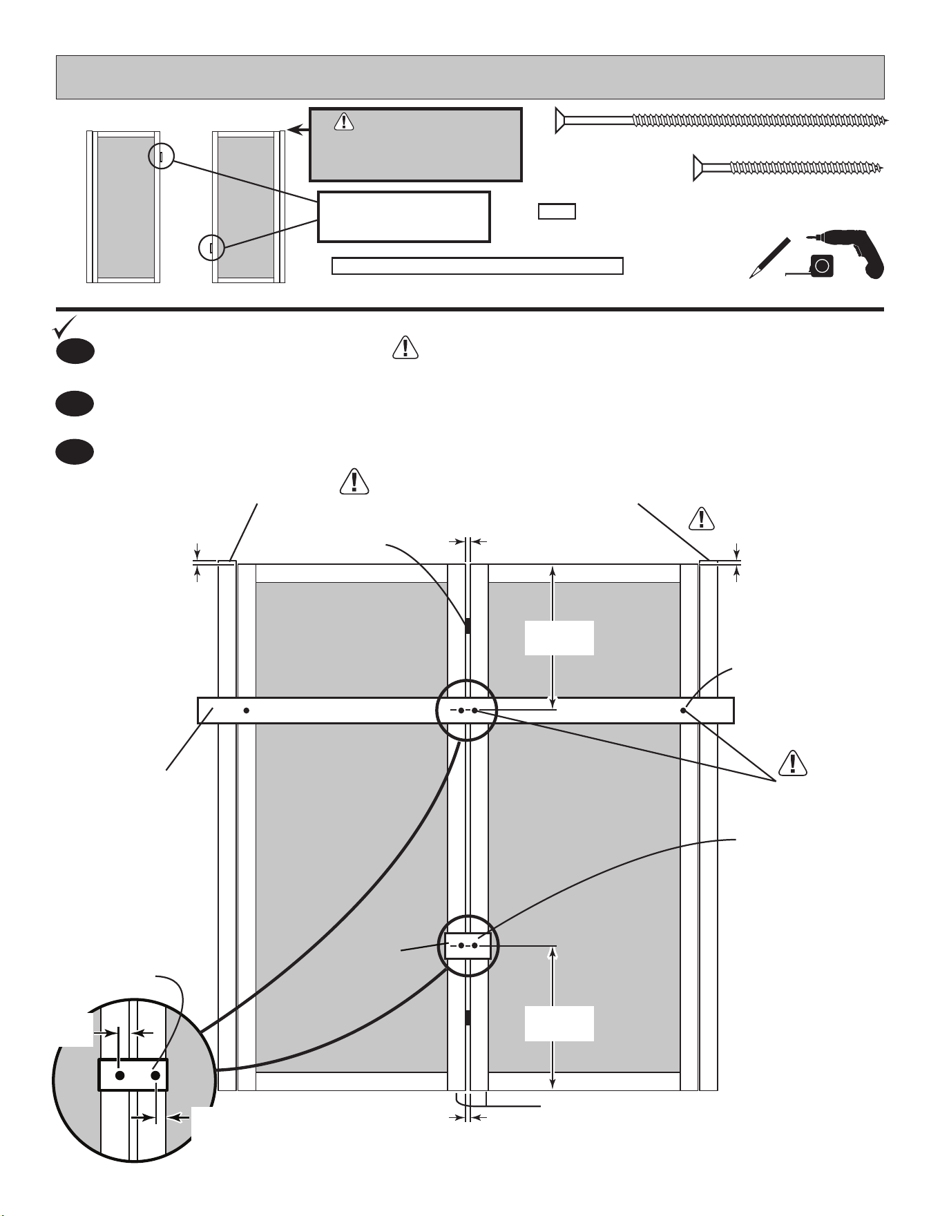
1-5/8" (4,1 cm)
Orient parts as shown on at surface. 3/8" offset is to top. Look for red
(right) and green (left) on hinge board.
PARTS REQUIRED:
x1x1
Left Door Right Door
BEGIN
1
DOUBLE DOORS - GABLE WALL
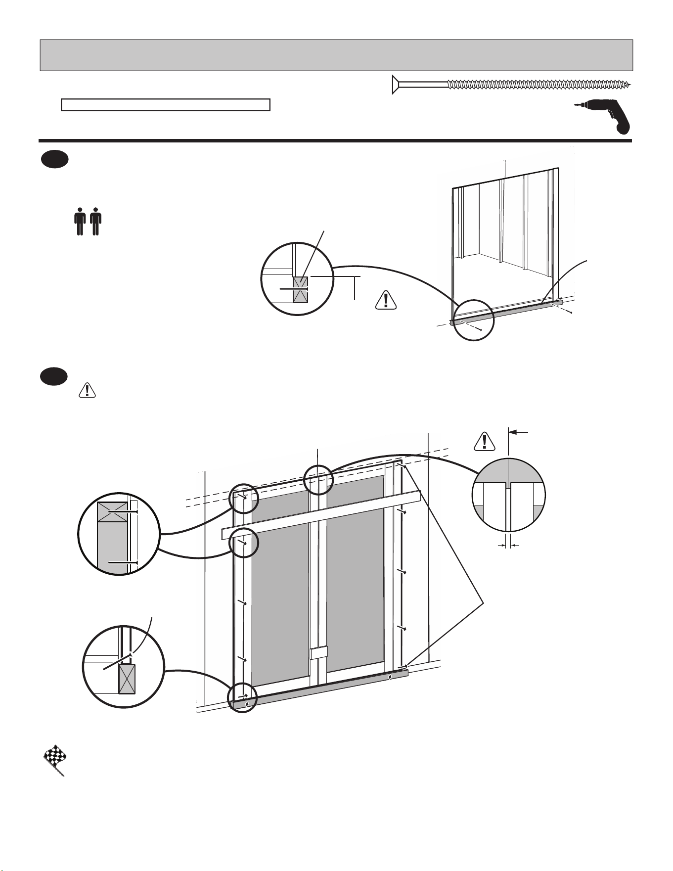
2
3
Attach temporary support OO with 3" screws in middle and at ends as shown.
Tighten securely.
Attach temporary support GAA with two 1-5/8" screws as shown.
Tighten securely.
HINT:
Look for 3/8" SPACER
attached to doors.
OO
GAA
Tighten screws
securely.
OFFSET
(4) 3" (7,6 cm)
Screws
Screws
1-5/8" (4,1 cm)
Bottom edges ush.
NOTE:
Screw hole
will be
used later.
3/8"
(1 cm)
3/8"
(1 cm)
3/8"
(1 cm)
3/8"
(1 cm)
OFFSET
GREEN
RED
3" (7,6 cm)
OO
x1
1-1/4 x 2-1/2 x 69" (3,2 x 6,3 x 175,3 cm)
3/4"
(1,9 cm)
23-1/2"
(59,7 cm)
23-1/2"
(59,7 cm)
3/4"
(1,9 cm)
x2
x4
IMPORTANT!
USE DOORS WITH
HINGE BOARD ENDS PAINTED
GREEN AND RED
SPACER
HIN T:
Use 3/8" SPACERS
to separate doors.
64
4
PARTS REQUIRED:
DOUBLE DOORS - GABLE WALL
OO
Flush
against wall panels.
Fig. A
OO
Center doors on panel seam as shown (Fig. B).
Remove temporary supports and check doors open properly.
FINISH
You have nished installing your double doors.
Screw hinge boards into wall supports and oor using ten 3" screws as shown.
Make sure screws go into framing and oor (Fig. C, D).
5
3" (7,6 cm)
Screws into the wall
support and oor frame.
Fig. B
SEAM
Fig. C
3/8"
(1 cm)
Fig. D
Angle 3" (7,6 cm)
Screw
Attach temporary support OO as a ledger board ush under wall
panels for doors to rest on, using two 3" screws
(Fig. A).
3" (7,6 cm)
x12
OO
x1
1-1/4 x 2-1/2 x 69" (3,2 x 6,3 x 175,3 cm)
65
DOUBLE DOORS - GABLE WALL
PARTS REQUIRED:
3/4" (1,9 cm)
x54
Two Screws
Fig. B
Door
Trim
3/4" (1,9 cm)
Screws from
behind.
Fig. A
Door
Panel
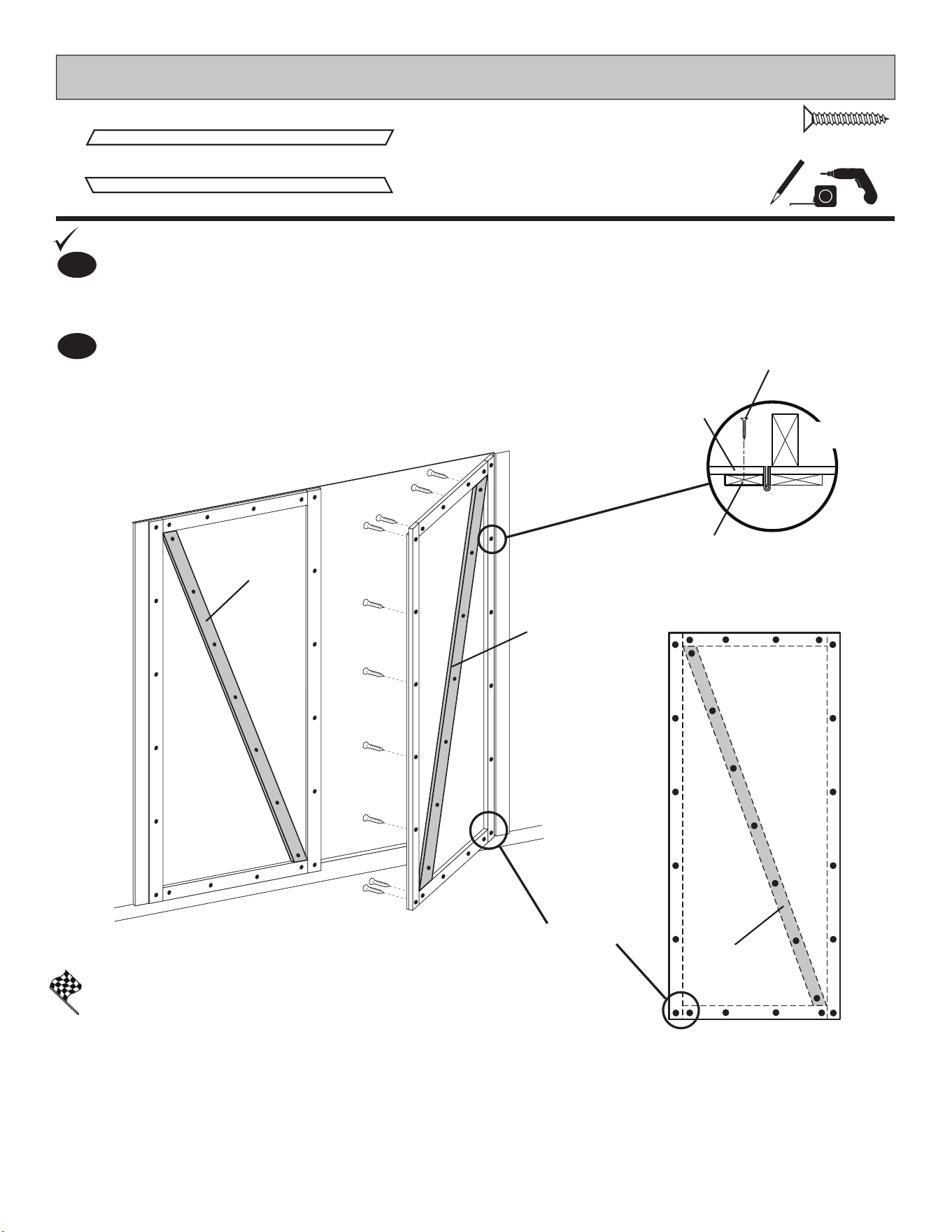
You have nished securing your door trim.
FINISH
BEGIN
1
Secure door trim from inside using 3/4" screws as shown (Fig. A).
2
Reinforce the door trim using 3/4" screws through door panel into trim (Fig. A).
Locate screws as shown (Fig. B). Use two screws at seams.
Attach DGL and DGR with 3/4" screws from inside of doors (Fig. B).
DGR
DGR
DGL
x1
19/32 x 2-1/2 x 70-7/8" (1,5 x 6,3 x 180 cm)
DGR
x2
19/32 x 2-1/2 x 70-7/8" (1,5 x 6,3 x 180 cm)
DGL
66
2"
(5,1 cm)
Screws
x12
14" (35,6 cm)
Approximately
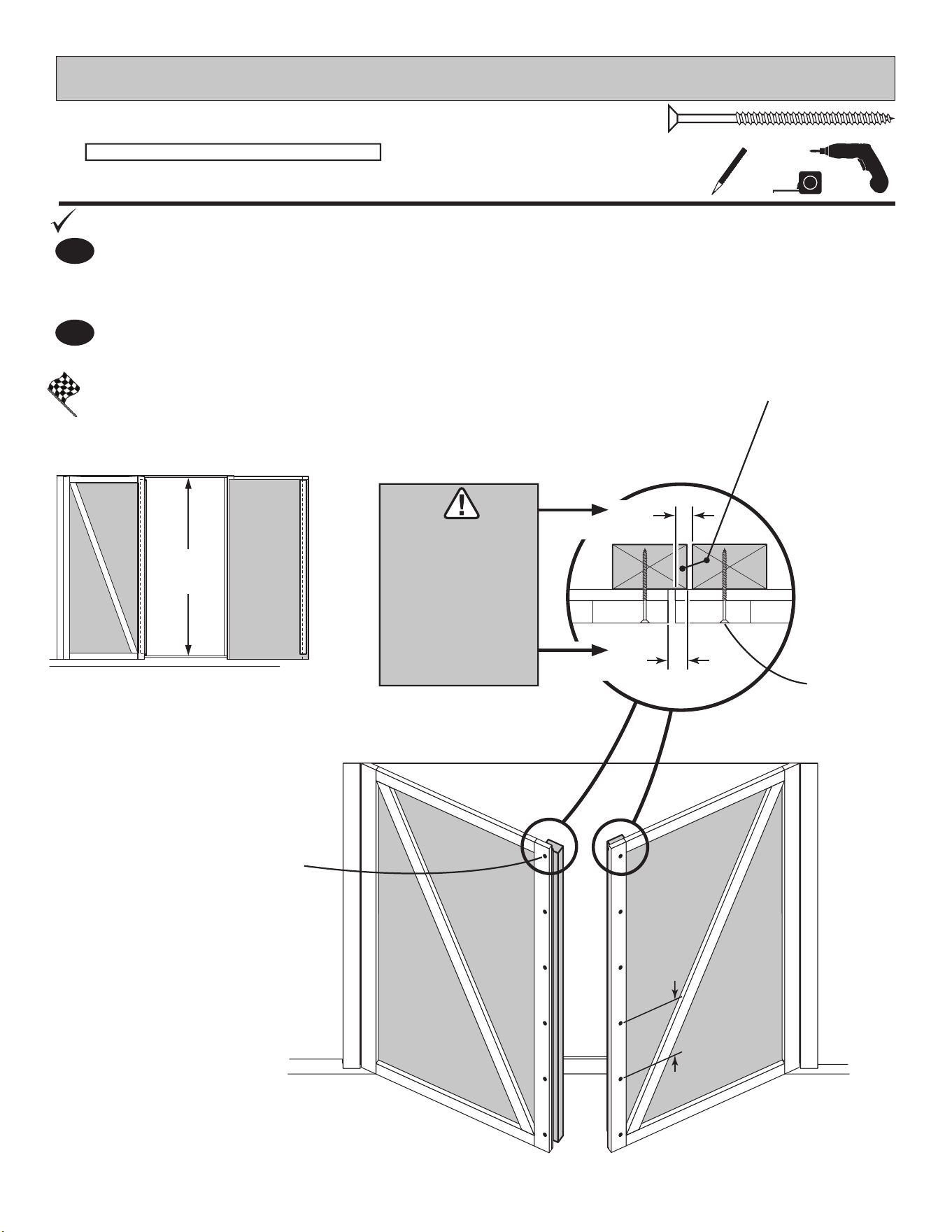
You have nished installing your door stiffeners.
BEGIN
Center OO vertically on the left door in the door opening ush with the edge of door (Fig. A).
1
PARTS REQUIRED:
x12
2" (5,1 cm)
DOUBLE DOOR STIFFENERS - GABLE WALL
FINISH
Repeat Step 1 to install OO on right door.
2
Secure using (6) 2" screws through outside trim into OO (Fig. B)
Fig. A
Center OO
in door
opening.
OO
x2
1-1/4 x 2-1/2 x 69" (3,2 x 6,3 x 175,3 cm)
OO x2
1"
(2,5 cm)
1"
(2,5 cm)
OFFSET
Screws 2"
(5,1 cm)
Fig. B
IT IS
IMPORTANT
TO HOLD
THESE
DIMENSIONS
67
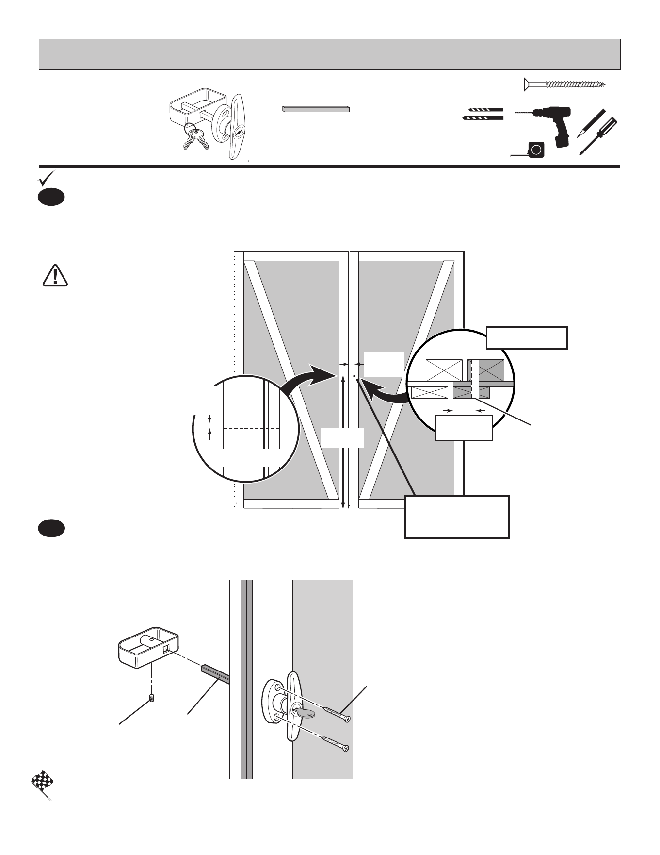
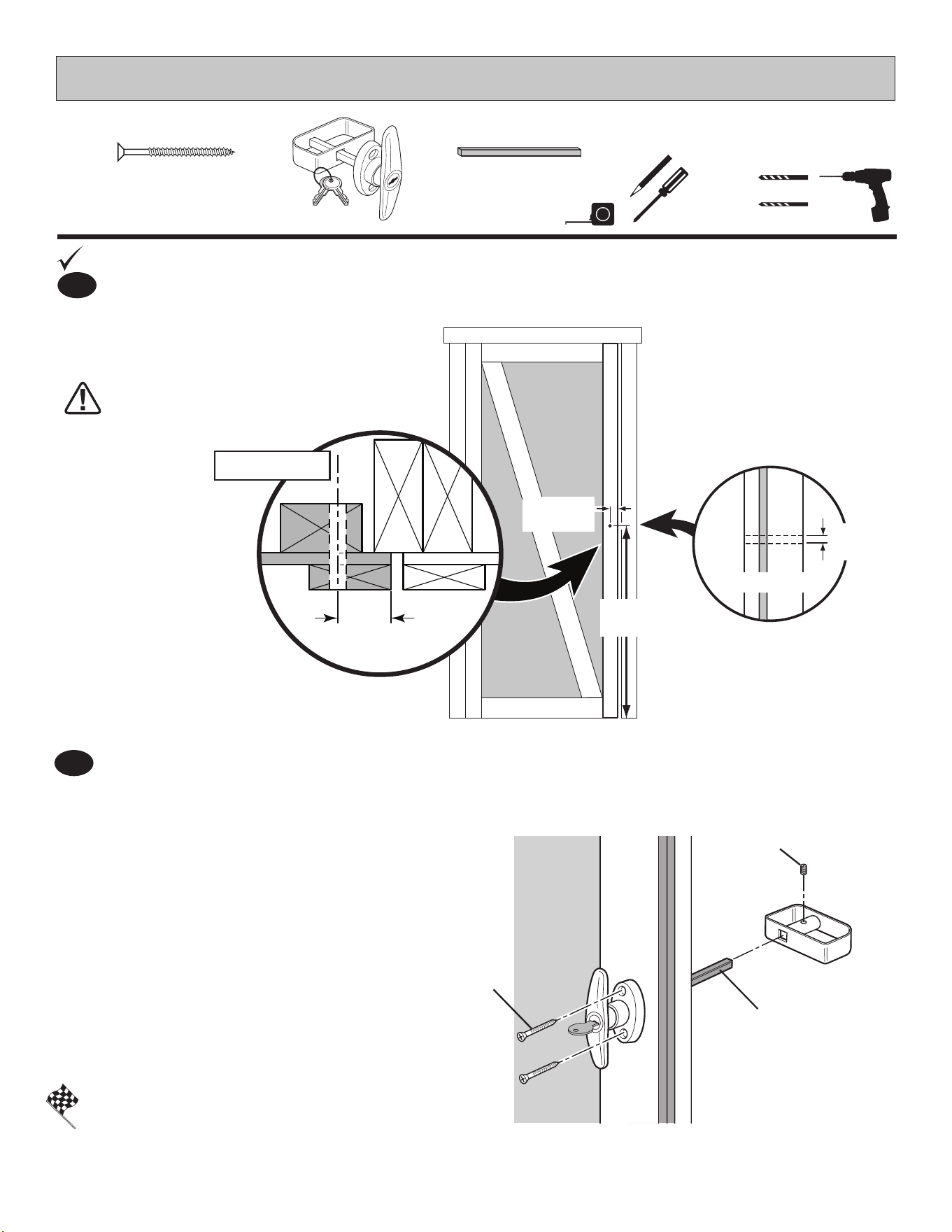
Measure and mark location of hole on outside of right door as shown (Fig. A).
Pre-drill pilot hole with 1/4" dril.
Pre-drill through hole with 1/2" drill.
Keep drilled hole square
to trim to avoid breaking
edge of door stiffeners.
BEGIN
1
Set Screw
1-1/2"
(3,8 cm) x2
1/2"
1,3 cm
1-1/2"
(3,8 cm)
35-3/4"
(90,8 cm)
SIDE VIEW
INSTALL ON
RIGHT DOOR.
TOP VIEW
1/4" (0,6 cm)
Pre-drill and
1/2" (1,2 cm)
Drill-through.
1/4" (0,6 cm)
1/2" (1,3 cm)
Drill Bits
You have nished installing your T-handle.
FINISH
2
Insert handle in hole and secure using 1-1/2" (3,8 cm) screws.
Attach inside handle and secure with set screw as shown.
x1
x2
1-1/2" (3,8 cm)
PARTS REQUIRED:
DOUBLE DOOR HARDWARE
1-1/2"
3,8 cm
4-1/2" Shaft
x1
4-1/2"
Shaft
Fig. A
68
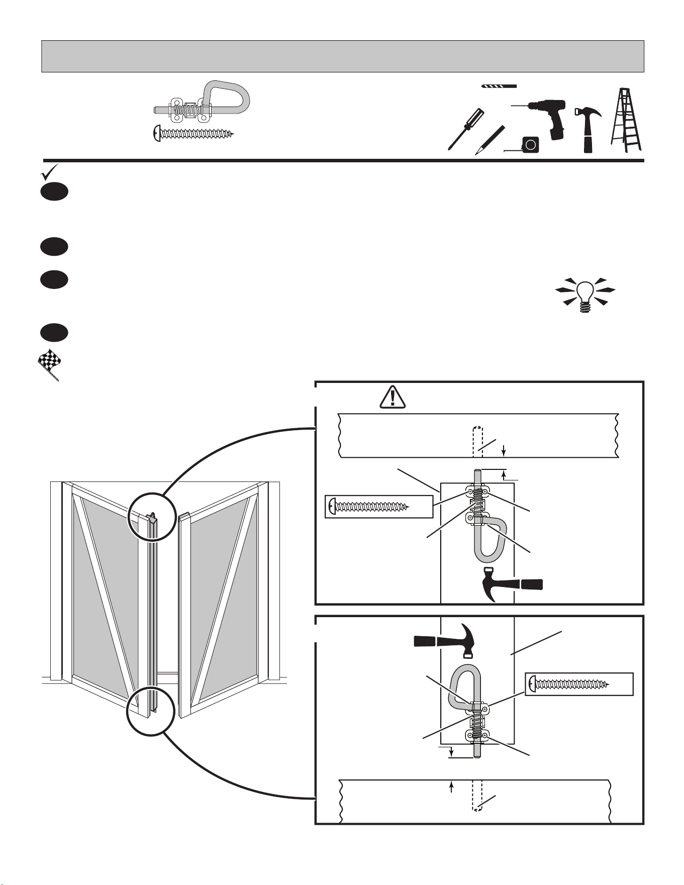
FINISH
2
3
4
Place top bolt onto OO in open position with bolt ends 3/8" (1 cm) down from frame.
Bolt is open when loop is contacting base (Fig A).
Mark and pre-drill holes for screws.
Install bolt with screws supplied and drill 5/16" (0,8 cm) hole deep enough
for bolt to slide into.
Place bottom bolt onto OO in open position with bolt ends 1/2" (1,3 cm) up from oor.
Bolt is open when loop is contacting base (Fig B).
Mark and pre-drill holes for screws.
Install bolt with screws supplied and drill 5/16" (0,8 cm) hole deep enough
for bolt to slide into.
You have nished installing
your Spring-Bolts.
LEFT
DOOR
5/16" (0,8 cm) Drill Bit
PARTS REQUIRED:
DOUBLE DOOR HARDWARE
HINT: With door
closed extend bolt
and tap with hammer
to leave a mark in
wood for drilling.
1" (2,5 cm)
x2
x8
Fig. A
Fig. B
OO
OO
FLOOR
PRE-DRILL
(4) HOLES
PRE-DRILL
(4) HOLES
3/8" (1 cm)
1/2" (1,3 cm)
1-1/4 x 2-1/2 x 69"
5/16" (0,8 cm) drill for
bolt. 1" (2,5 cm) deep.
5/16" (0,8 cm) drill for
bolt. 1" (2,5 cm) deep.
OVER DOOR
FRAME
LOCATE AND PRE-DRILL HOLES
TO AVOID SPLITTING WOOD
OPEN POSITION
spring is loose.
OPEN POSITION
spring is loose.
Loop contacts
base.
Loop contacts
base.
x4
x4
with bolt
in open
position.
1-1/4 x 2-1/2 x 69"
BEGIN
1
69
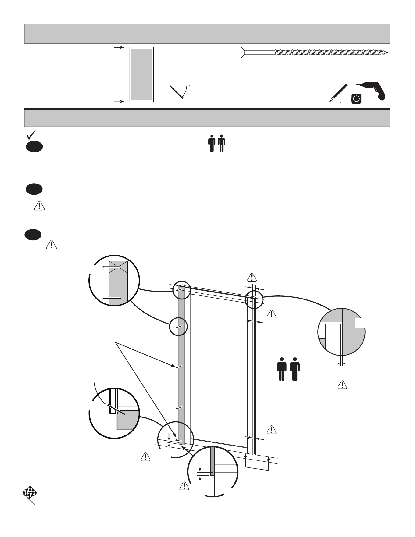
PARTS REQUIRED:
SINGLE DOOR - FRONT WALL
Refer to Page 20 for right hand swing single door note.
3" (7,6 cm)
x5
Center door in wall panel opening.
Hold door in position and keep level.
Install single door with black-painted hinge board.
FINISH
You have nished installing your single door.
2
3" (7,6 cm)
Screws
into the wall support
and oor frame.
3
Screw hinge board into wall supports and oor using ve 3" screws as shown.
Make sure screws go into framing and oor (Fig. D, Fig. E).
Measure Gap (Fig. B) between door trim and wall panel as shown.
Hold door in position and keep level.
Hinge-board must overhang wall panel at measurement shown (Fig. C).
Bottom of door trim is even with wall panel as shown.
5/8"
(1,0 cm)
5/8"
(1,6 cm)
5/8"
(1,6 cm)
5/8"
(1,6 cm)
BEGIN
1
x1
Painted
Black
on Ends
UNIVERSAL DOOR
Left
Angle 3" (7,6 cm)
Screw
Fig. E
Fig. D
Fig. B
3/8"
(1,0 cm)
Fig. C
3/8"
(1,0 cm)
Door trim even
with panel.
x1
19/32 x 2-1/2 x 70-7/8" (1,5 x 6,3 x 180 cm)
DGL
70
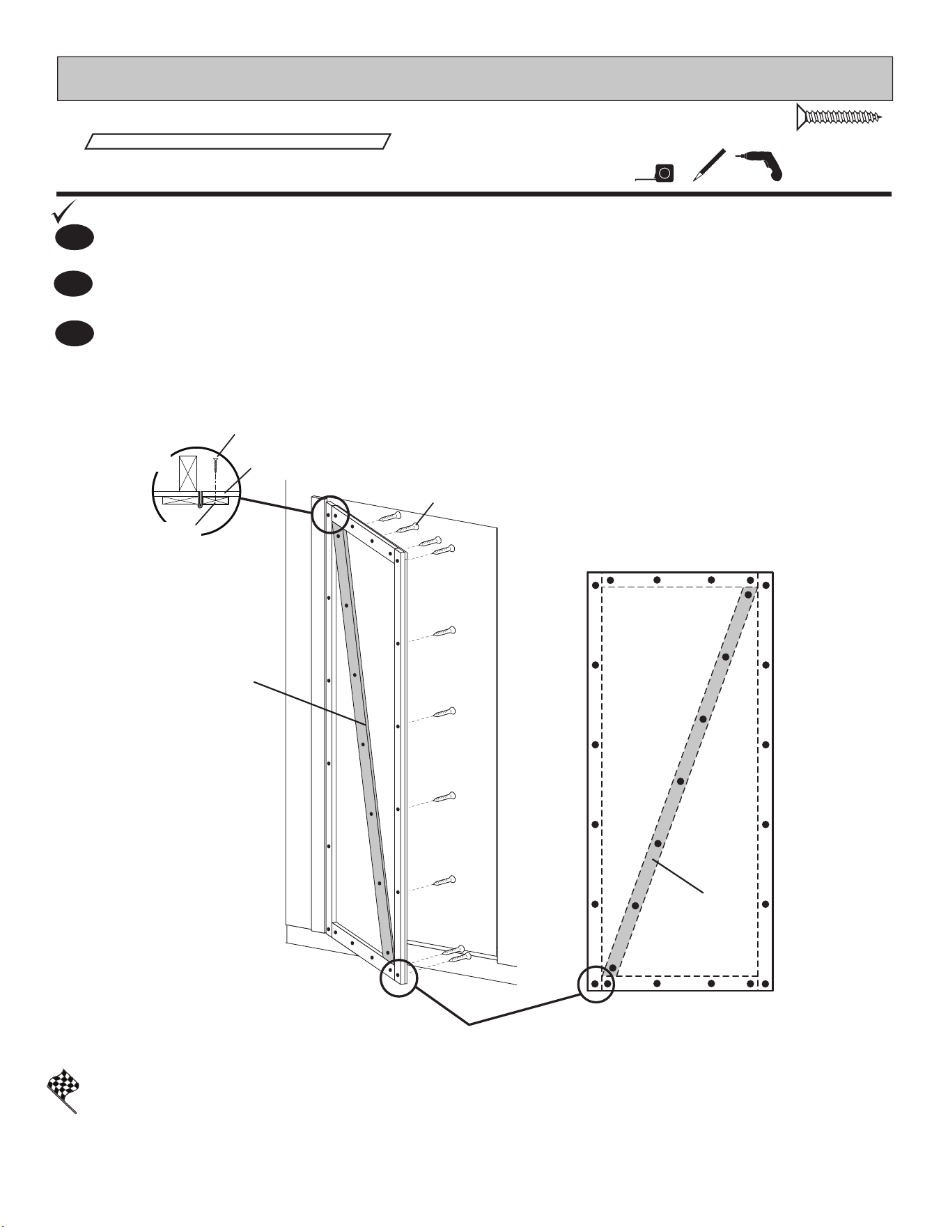
SINGLE DOOR TRIM - FRONT WALL
PARTS REQUIRED:
3/4" (1,9 cm)
x27
Door
Trim
Fig. A
Door
Panel
3/4" (1,9 cm)
Screws from
behind.
3/4" (1,9 cm)
Screws from
behind.
Two Screws
You have nished securing your door trim.
FINISH
BEGIN
1
Secure door trim from inside using 3/4" screws as shown (Fig. A).
3
Reinforce the door trim using 3/4" screws through door panel into trim (Fig. A).
Locate screws as shown in Fig. B. Use two screws at seams.
Fig. B
DGL
DGL
Attach DGL with 3/4" screws from inside of door. (Fig. B).
2
INSIDE
OF
DOOR
71
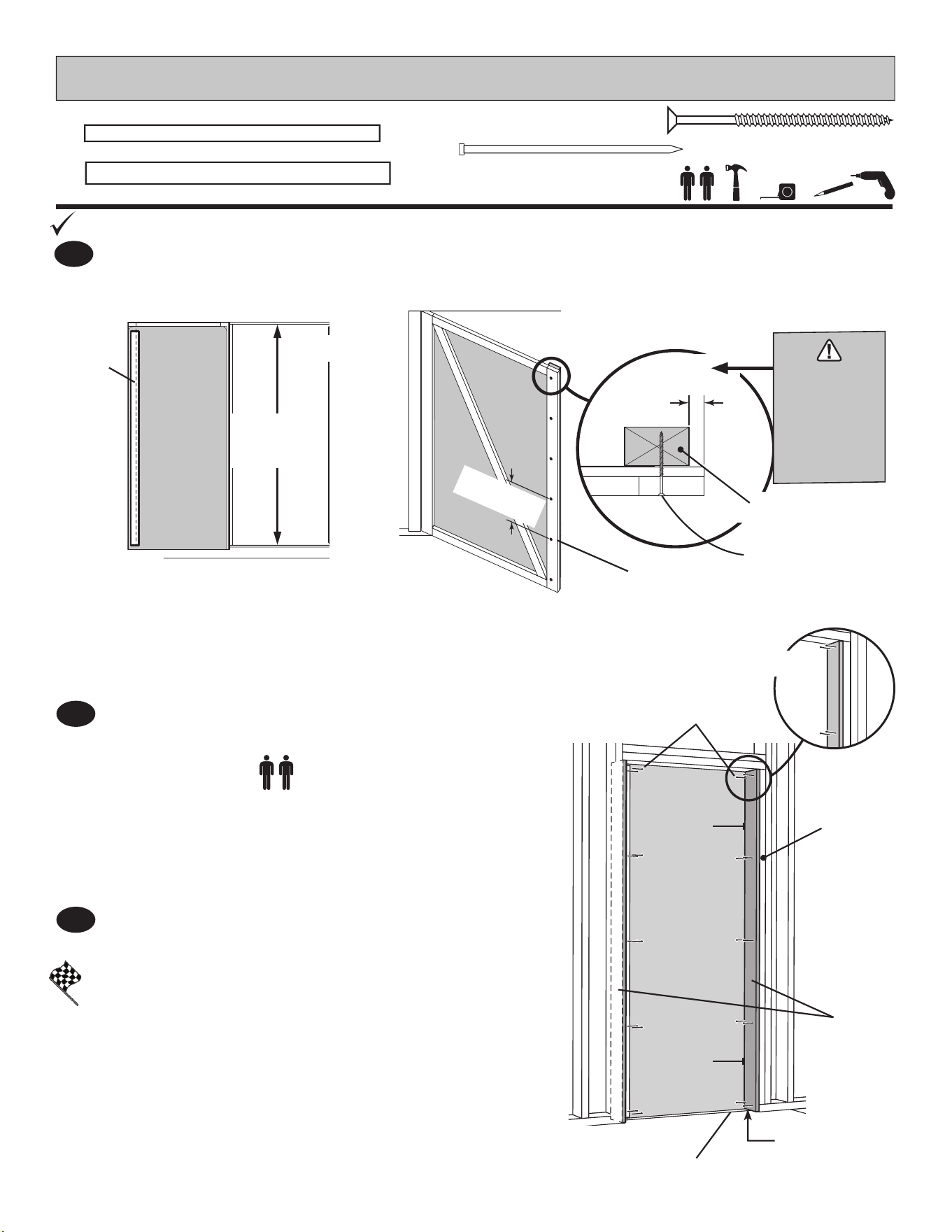
BEGIN
Center OO vertically on door in the door opening (Fig. A) 1" from edge of door (Fig. B).
1
PARTS REQUIRED:
x6
2" (5,1 cm)
DOOR STIFFENER & WEATHER STRIP - FRONT WALL
Secure using (6) 2" screws through outside trim into OO (Fig. B)
Fig. A
Center OO
in door
opening.
You have nished installing your weatherstrip and threshold.
FINISH
Hold LRA tight against inside of door (Fig. D).
Secure LRA using 2" nish nails into right door
frame as shown.
2
3
Repeat Step 2 to install LRA on other side of door opening.
OO
x1
1-1/4 x 2-1/2 x 69" (3,2 x 6,3 x 175,3 cm)
2"
(5,1 cm)
Screws
x6
14" (35,6 cm)
Approximately
1"
(2,5 cm)
2" Screws
(5,1 cm)
Fig. B
OO
IT IS
IMPORTANT
TO HOLD
THIS
DIMENSION
LRA
x2
1 x 4 x 69-3/4" (2,5 x 10,2 x 177,2 cm)
x20
2" (5,1 cm)
OO
2"
(5,1 cm) Finish
Nails
x20
Flush
Metal Threshold
Door Frame
Flush
Flush
LRA
INSIDE
OF
DOOR
Fig. D
72
DOOR HARDWARE - SINGLE DOOR
PARTS REQUIRED:
1/2" (13 mm) Drill Bit
1/4" (6 mm) Drill Bit
35-3/4"
(90 cm)
1/2"
1,3 cm
SIDE VIEW
Measure and mark location of hole on outside of door as shown (Fig.A).
Pre-drill pilot hole with 1/4" dril.
Pre-drill through hole with 1/2" drill.
Keep drilled hole square
to trim to avoid breaking
edge of door stiffener.
You have nished installing your T-handle.
BEGIN
1
Fig. B
Set Screw
1-1/2"
(3,8 cm) x2
FINISH
2
Insert handle in hole and secure using 1-1/2" (3,8 cm) screws (Fig. B).
Attach inside handle and secure with set screw as shown.
x1
x2
1-1/2" (3,8 cm)
TOP VIEW
1-1/2"
3,8 cm
5-1/2"
Shaft
1-1/2"
(3,8 cm)
Fig. A
5-1/2" Shaft
x1
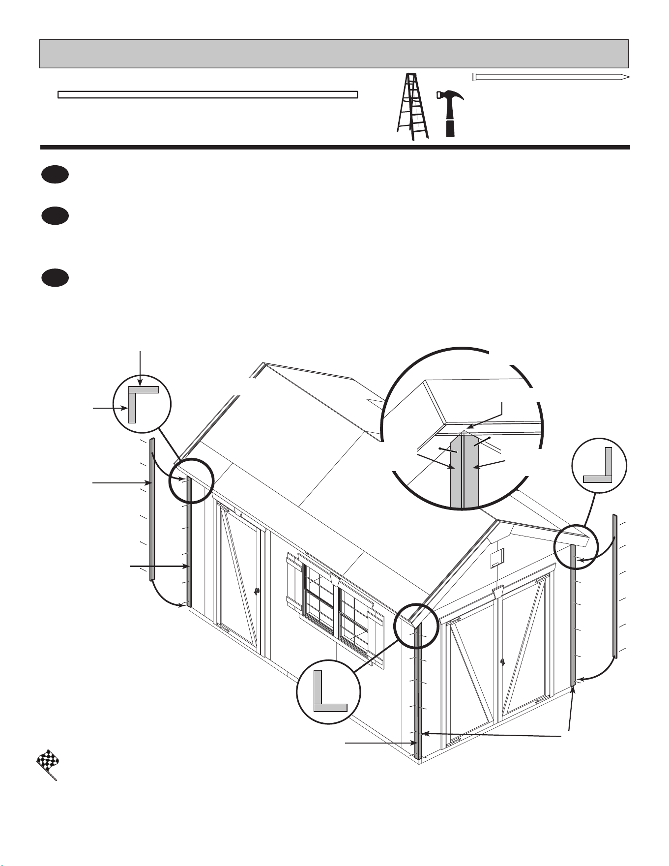
73
CORNER TRIM
PARTS REQUIRED:
x48
2" (5,1 cm)
BEGIN
¸
1
FINISH
Position 81-1/2" trim board ush along edge of installed 81-1/2" trim board and ush under
gable panel (Fig. A, B). Secure using one 2" nish nail at top as shown.
Attach one 81-1/2" trim board ush under sof t panel and against eave wall (Fig. A, B) using
one 2" nish nail at top as shown.
Repeat Steps 1 - 2 to attach trim to all four corners.
Finish attaching trim ush to corners (Fig. B) using (6) 2" (5,1 cm) nish nails as shown.
You have attached your corner trim.
3
2
81-1/2"
(207 cm)
on eave
walls
81-1/2"
(207 cm)
on gable
wall
81-1/2"
(207 cm)
x8
3/8 x 1-3/4 x 81-1/2" (1 x 4,4 x 207 cm)
Fig. A
Fig. B
81-1/2"
(207 cm)
81-1/2"
(207 cm)
81-1/2"
(207 cm)
Flush under gable trim.
81-1/2"
(207 cm)
81-1/2"
(207 cm)
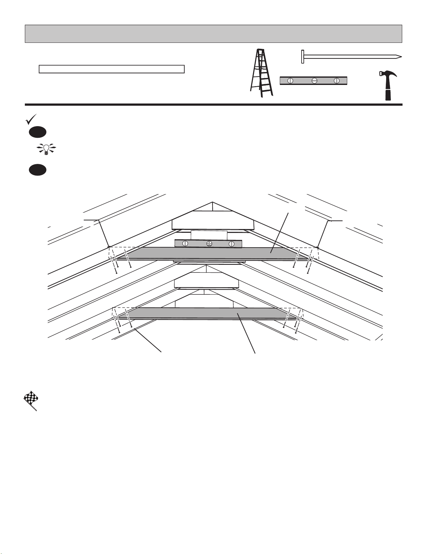
x2
1 x 4 x 60" (2,5 x 10,2 x 152,4 cm)
74
PARTS REQUIRED:
COLLAR TIES
FINISH
You have nished installing your collar tie.
2
1
BEGIN
Position and level collar ties JF on 3rd and 5th rafters from double door wall.
HINT: For best appearance install collar ties on rafters facing away from double door opening.
Attach with
2" nails as shown.
x12
2" (5,1 cm)
JF
3rd Rafter
5th Rafter
JF
JF
Flush
Flush
2" (5,1 cm) Nails
LEVEL
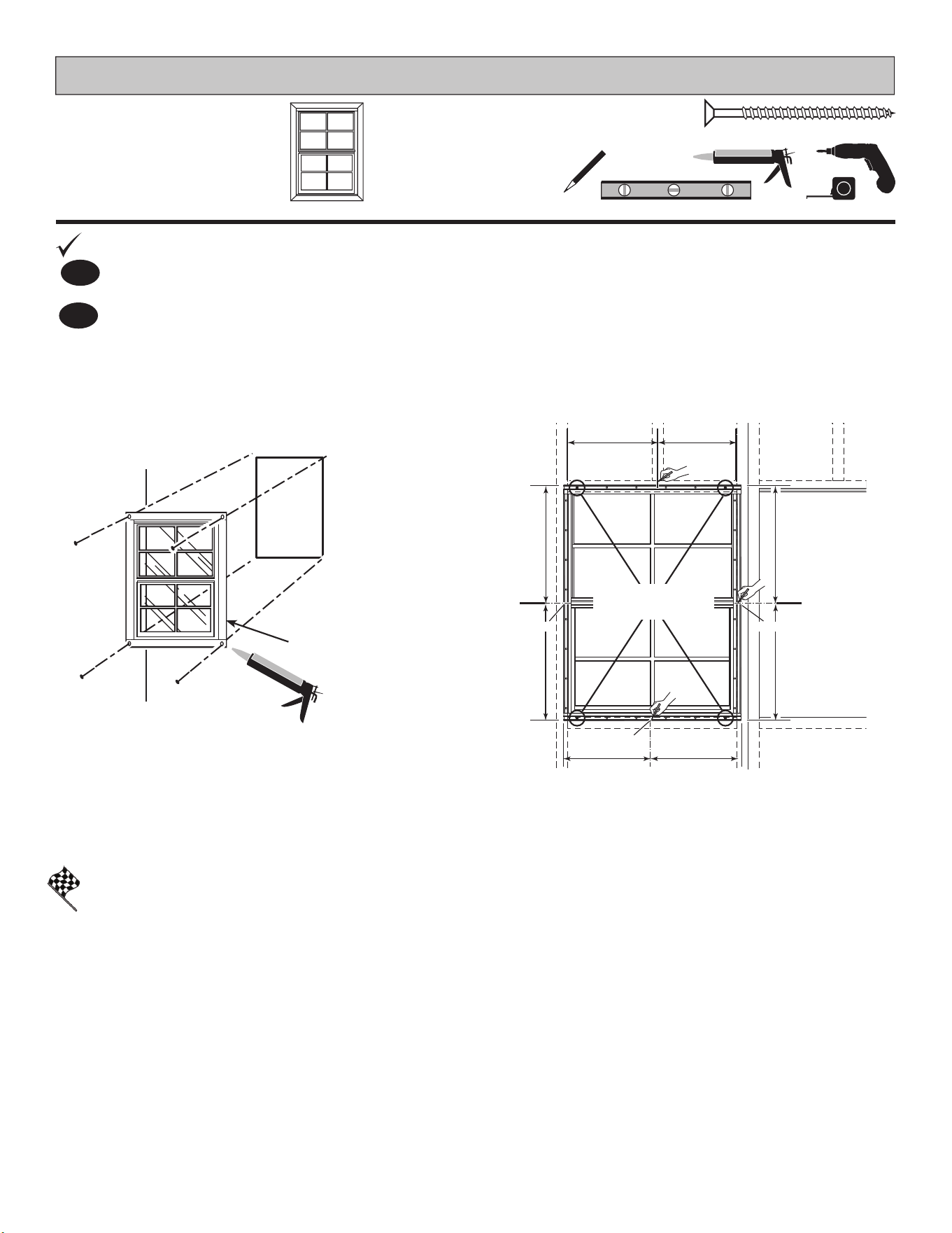
75
Window
22-1/4 x 29-3/4"
(56,5 x 75,6 cm)
x2
PARTS REQUIRED:
WINDOWS
CENTER
CENTER
CENTER
1-5/8" (4,1 cm)
x8
Caulk behind
frame near edge.
Fig. A
FINISH
You have nished installing your windows.
Fig. B
BEGIN
1
Center and secure windows using 1-5/8" screws as shown. Ensure window is level.
Seal windows with high-quality exterior-grade caulk before installing (Fig. A).
2
1-5/8" (4,1 cm)
Screws
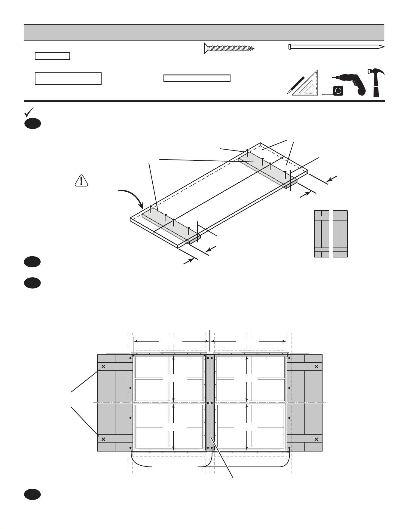
76
SHUTTERS & WINDOW TRIM
2
Repeat Step 1 to build 2nd shutter.
PARTS REQUIRED:
1" (2,5 cm)
x20
Locate AZ centered on marks and seam as shown. Attach using 2" nish nails.
Nail into double studs.
Position DHA on top of DJA primed side down as shown. Square and mark.
Attach DHA using 1" screws.
Flush
2-1/2"
(6,3 cm)
2-1/2"
(6,3 cm)
Parts primed side down
Flush
DHA
DJA
AZ
x4
19/32 x 2-1/2 x 30-1/8" (1,5 x 6,3 x 76,5 cm)
AZ
2" (5,1 cm)
Finish Nails
into wall frame
1" (2,5 cm)
Screws
BEGIN
1
x4
19/32 x 2-1/2 x 11" (1,5 x 6,3 x 27,9 cm)
DJA
x4
19/32 x 5-1/2 x 30-1/8" (1,5 x 14 x 76,5 cm)
DHA
x14
2" (5 cm)
3
4
Locate shutter just past the inside of the vertical screw holes on window ange.
Center shutter from top to bottom of window as shown.
Attach shutter using 2" nish nails indicated at "dot". Nail into wall studs.
From inside, attach shutter using 1" screws indicated at "X".
Repeat steps to attach shutter on opposite side.
1" Screws
from inside
CENTER CENTER
CENTER CENTER
CENTERCENTER
Assembled Shutters
x2
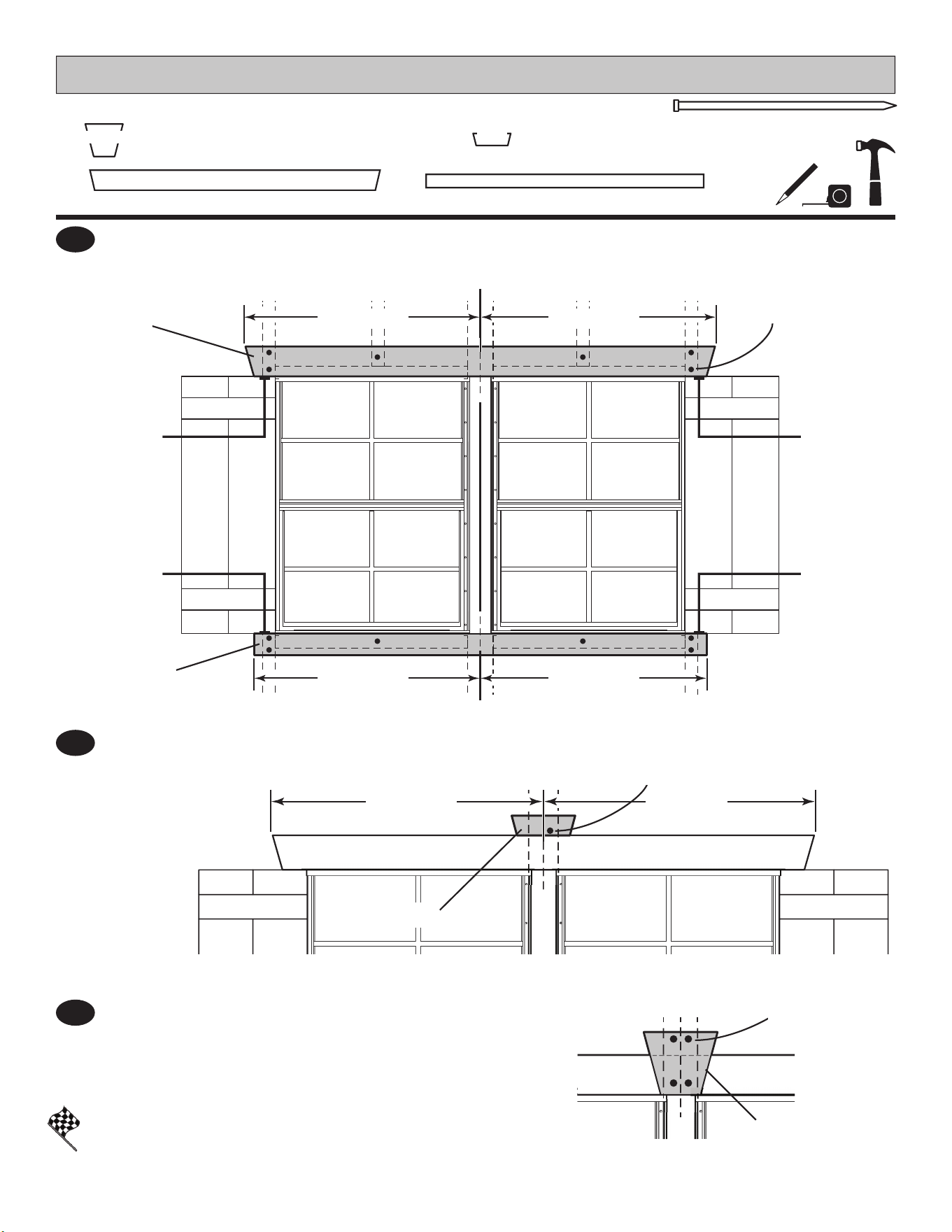
77
FINISH
PARTS REQUIRED:
5
6
7
Locate DEA and AUA centered and ush to shutters as shown.
Attach using 2" nish nails. Nail into framing.
Locate JTA centered over trim.
Attach using one 2" nish nail as shown.
Nail into framing.
Place NRA keystone centered over JTA.
Attach using four 2" nish nails as shown. Nail into framing.
You have nished installing your shutters and window trim.
x17
2" (5 cm)
WINDOW TRIM (cont.)
AUA
x1
2 x 2-1/2 x 53" (5,1 x 6,3 x 134,6 cm)
DEA
x1
2 x 3-1/2 x 55" (5,1 x 8,9 x 139,7 cm)
CENTER
CENTER
CENTER
CENTER
CENTER
CENTER
FlushFlush
FlushFlush
DEA
AUA
JTA
NRA
2" (5,1 cm)
Finish Nails
into wall frame
2" (5,1 cm)
Finish Nails
into wall frame
2" (5,1 cm)
Finish Nails
into wall frame
x1
19/32 x 6-7/16 x 5-1/2" (1,5 x 17,5 x 14 cm)
NRA
x1
19/32 x 6-7/16 x 2" (1,5 x 16,4 x 5,1 cm)
JTA
Mark
Mark
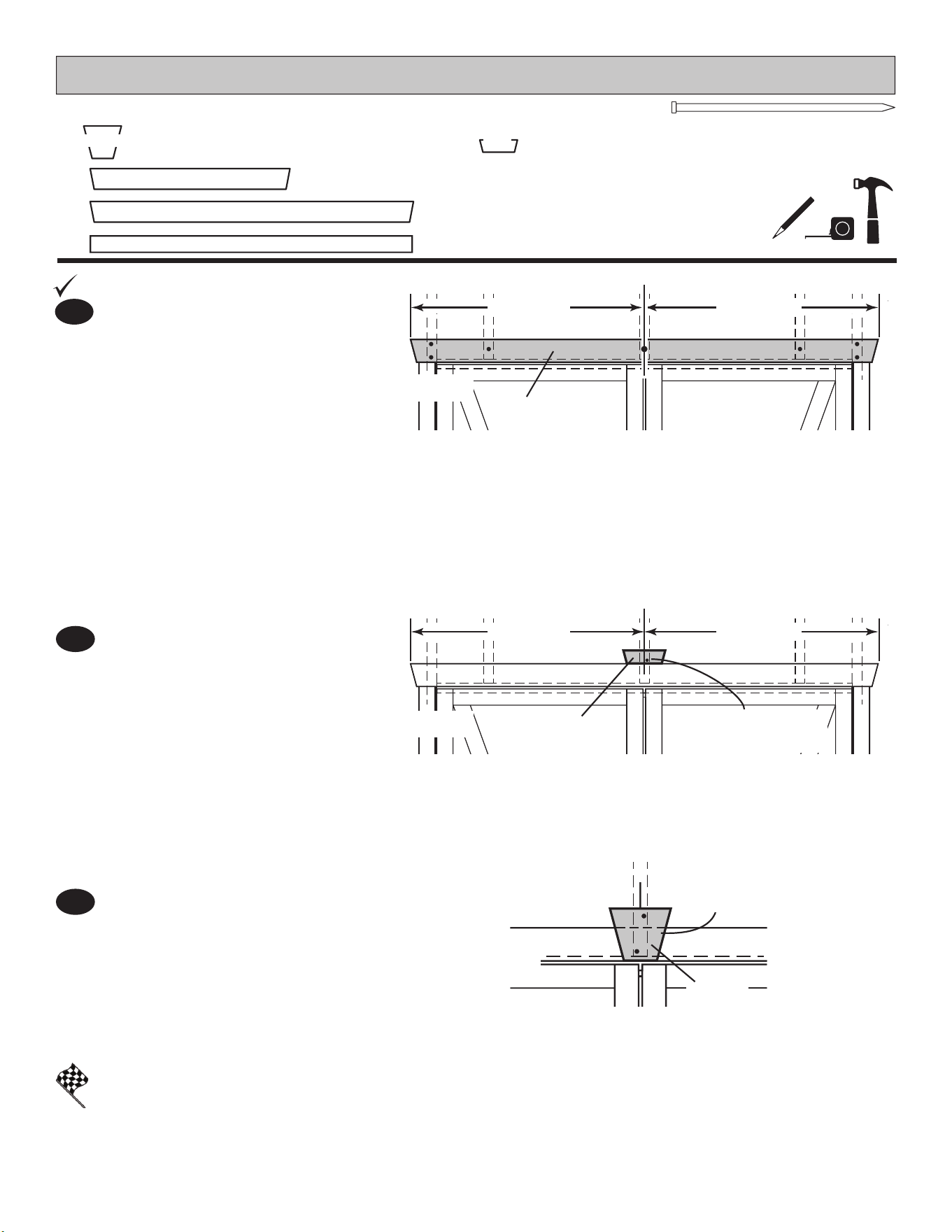
78
x10
2" (5 cm)
2
3
Locate JTA centered over trim
(Fig. B).
Attach using one 2" nish nail,
close to trim as shown.
Nail into framing.
Place NRA centered over JTA (Fig. C).
Attach using four 2" nish nails as shown.
Nail into framing and top trim.
PARTS REQUIRED:
DOOR TRIM
NRA
CENTER
CENTER
CENTER
CENTER
Center trim DFA over double doors
ush to hinge boards.
Secure using 2" nish nails into
framing as shown (Fig. A).
x1
DFA
19/32 x 3-1/2 x 72" (1,5 x 8,9 x 182,9 cm)
ZJ
x1
19/32 x 2-1/2 x 72" (3,2 x 6,3 x 182,9 cm)
x1
DDA
19/32 x 3-1/2 x 40" (1,5 x 8,9 x 101,6 cm)
x2
19/32 x 6-7/16 x 5-1/2" (1,5 x 17,5 x 14 cm)
NRA
x1
19/32 x 6-7/16 x 2" (1,5 x 16,4 x 5,1 cm)
JTA
BEGIN
1
Fig. B
Fig. C
Fig. A
DFA
2" (5,1 cm)
Finish Nail
into wall frame
2" (5,1 cm)
Finish Nails
into wall frame
JTA
FINISH
You have nished installing your double door trim.
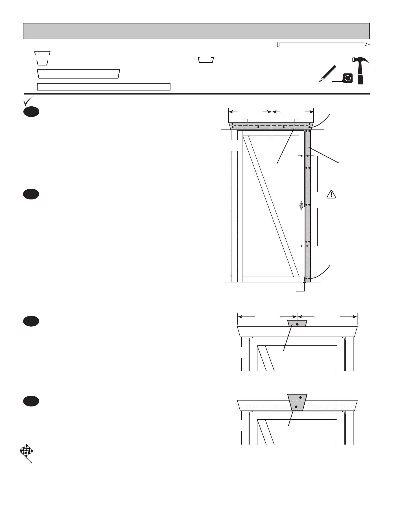
79
Fig. D
x19
2" (5 cm)
PARTS REQUIRED:
DOOR TRIM
ZJ
DDA
Flush ZJ with bottom of wall panel and single
door (Fig. D).
Ensure 3/8" gap between door and trim (Fig. D).
Secure using 2" nish nails into framing
as shown.
2
ZJ
x1
19/32 x 2-1/2 x 72" (3,2 x 6,3 x 182,9 cm)
x1
DDA
19/32 x 3-1/2 x 40" (1,5 x 8,9 x 101,6 cm)
3/8"
(1,0 cm)
CENTER
FlushFlush
Flush
CENTER
CENTER CENTER
x1
19/32 x 6-7/16 x 5-1/2" (1,5 x 17,5 x 14 cm)
NRA
x1
19/32 x 6-7/16 x 2" (1,5 x 16,4 x 5,1 cm)
JTA
NRA
JTA
BEGIN
1
Center trim DDA over door ush to
hinge board and ZJ.
Secure using 2" nish nails into framing
as shown (Fig. D).
2" (5,1 cm)
Finish Nails
into wall frame
2" (5,1 cm)
Finish Nails
into wall frame
FINISH
3
4
Locate JTA centered over door trim.
Attach using one 2" nish nail close to trim as shown
(Fig. E).
Place NRA centered over JTA.
Attach using ve 2" nish nails as shown (Fig. F).
Nail into JTA and framing at bottom.
You have nished installing your single door trim.
Fig. E
Fig. F
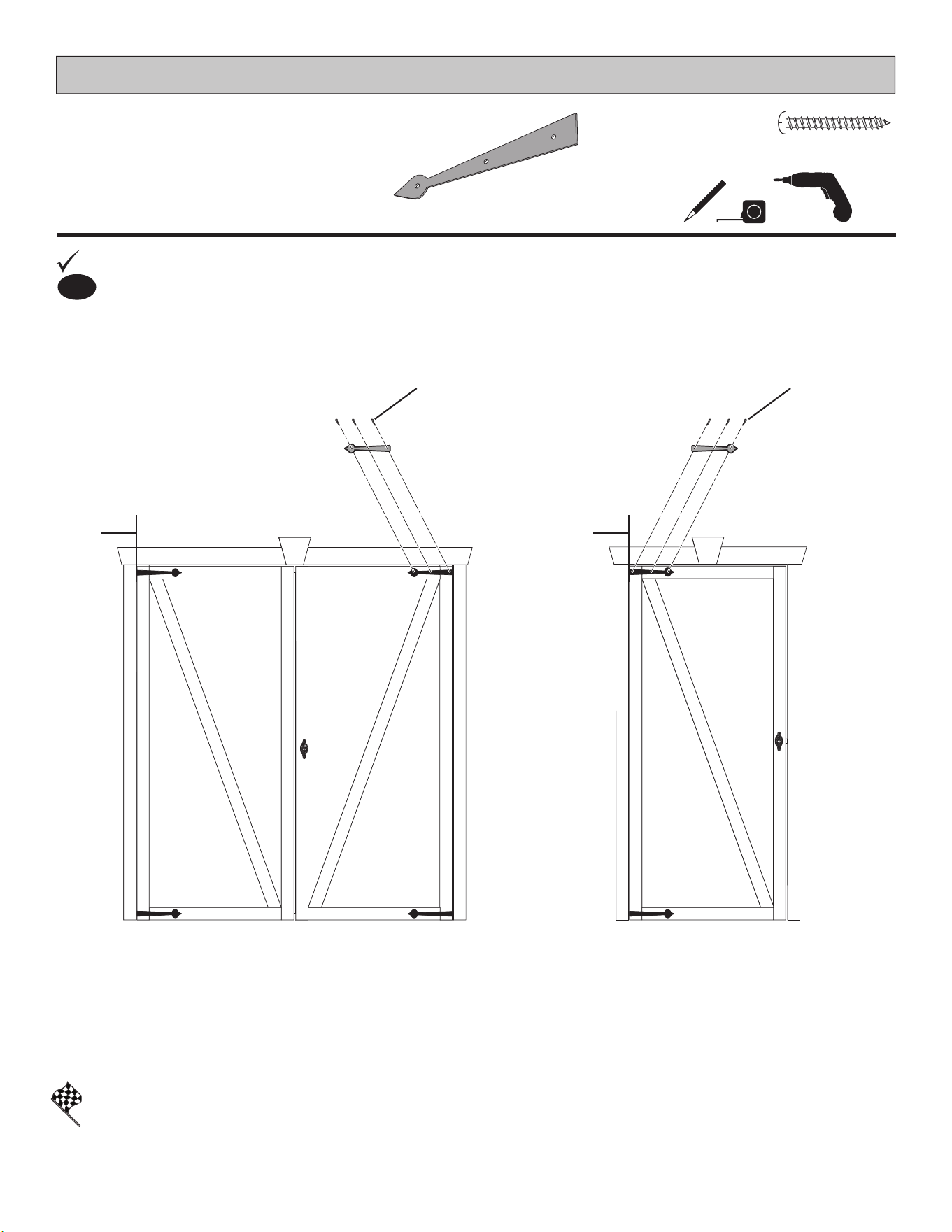
80
DOOR - DECORATIVE HINGES
x18
1" (2,5 cm)
x6
FINISH
PARTS REQUIRED:
BEGIN
1
You have nished installing your decorative door hinges.
Level decorative hinges in position as shown.
Secure with 1" (2,5 cm) screws.
1" (2,5 cm)
Screws
1" (2,5 cm)
Screws
FlushFlush
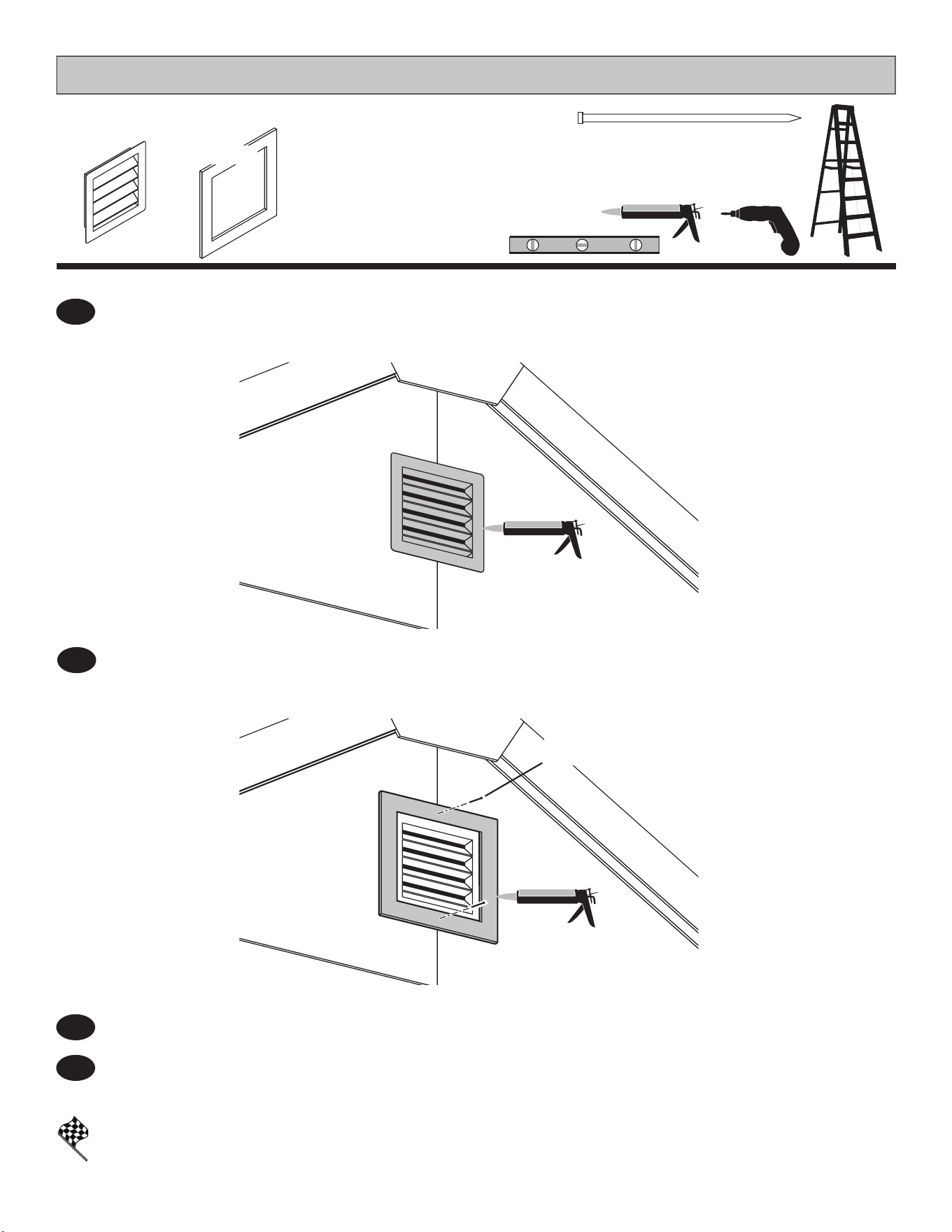
81
FINISH
PARTS REQUIRED:
2
BEGIN
¸
1
You have nished installing your vents.
GABLE VENTS
#15021
Repeat Steps 1-3 to install vent and frame on the other gable wall.
3
4
x2
Vent with Frame
Secure vent frame using 2" nish nails (Fig. B).
x2
2" (5 cm)
2" (5 cm)
Nails
Fig. A
Fig. B
Center vent frame over vent. Ensure frame is level.
Seal vent trim from behind with high-quality exterior-grade caulk before installing (Fig. B).
Place vent in gable opening. Seal vent behind vent ange edges with high-quality
exterior-grade caulk before installing (Fig. A).
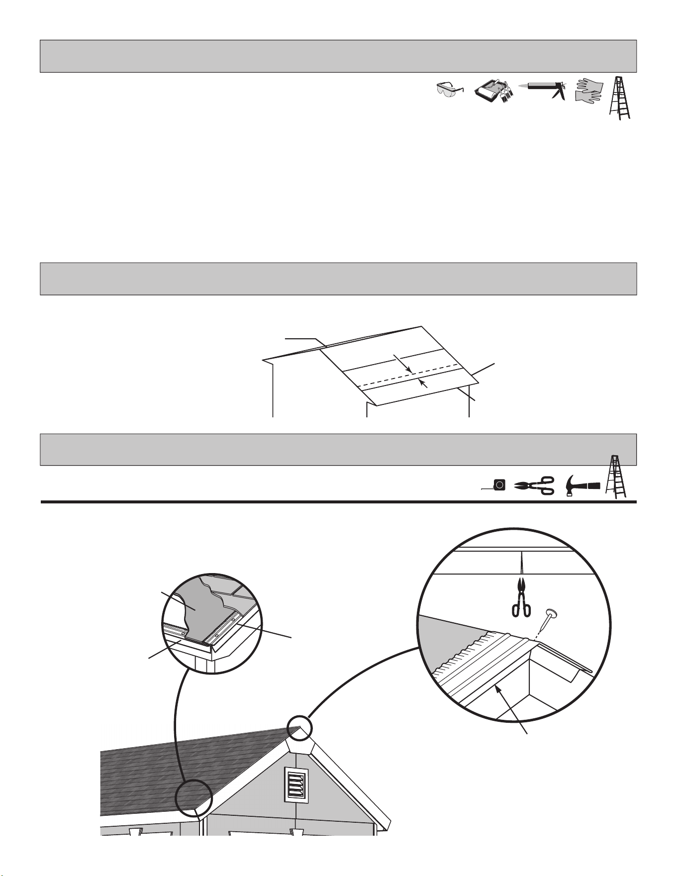
82
• Use acrylic latex caulk that is paintable. Caulk at all horizontal and vertical seams, between the trim and walls, and all
around the door trim.
• Use a high quality exterior acrylic latex paint. When painting your building, there are a few key areas that can be easily
overlooked that must be painted:
• Bottom edge of all siding and trim
• Inside of doors and all 4 edges
Note:
Prime all un-primed exterior wood before painting.
(Follow directions provided by manufacturer.)
Snip bottom side of drip edge and
bend over to other side of roof.
(Follow directions provided by manufacturer.)
PAINT & CAULK
- NOT INCLUDED -
ROOF FELT
- NOT INCLUDED -
DRIP EDGE
- NOT INCLUDED -
• Install felt ush to all roof edges overlapping 3". Use minimal amount of roo ng nails to hold in place.
OK to overlap at ridge.
3" OVERLAP
Flush
Flush
Edge ush
to trim.
• Install drip edge over roof felt on gable side and under roof felt on eave side (Fig. A).
• Do not use nails on side of drip edge that hangs over side of building.
• Only nail top of drip edge as shown.
Roof Felt
Drip Edge
Drip Edge
Fig. A
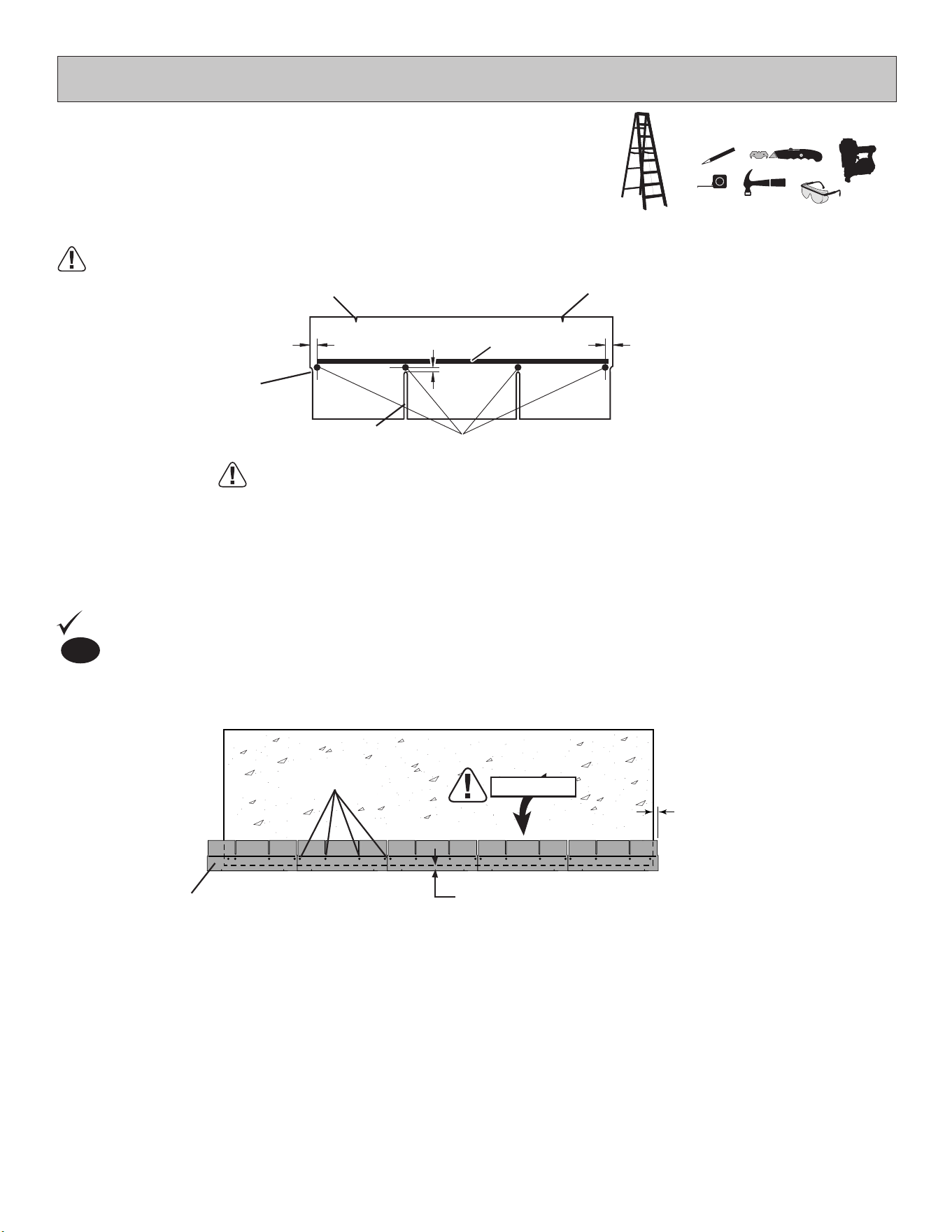
83
• Follow directions provided by manufacturer and these instructions.
SHINGLES
- NOT INCLUDED -
Install rst starter row upside down and color up with a 1" overhang at back and bottom of roof panel. Use (4) nails per shingle.
Starter row must be straight and level all the way across with lower edge of roof deck.
NOTE: If you have installed drip edge install shingles ush to drip edge.
BEGIN
1
TABS UP
Shingle overlaps
roof decking.
1" (2,5 cm) overhang
past roof deck.
1" (2,5 cm) overhang or
ush with drip edge.
(4) Nails
BACK OF SHEDFRONT OF
SHED
NEVER DRIVE FASTENERS INTO OR ABOVE SEALING STRIPS.
Familiarize yourself with a 3-Tab Shingle.
SHINGLE NAIL PATTERN
1"
(2,5 cm)
NAILS
Sealing Strip
1"
(2,5 cm)
1/2"
(1,3 cm)
Full Rain Slot
Half A Rain Slot
Notch
Notch
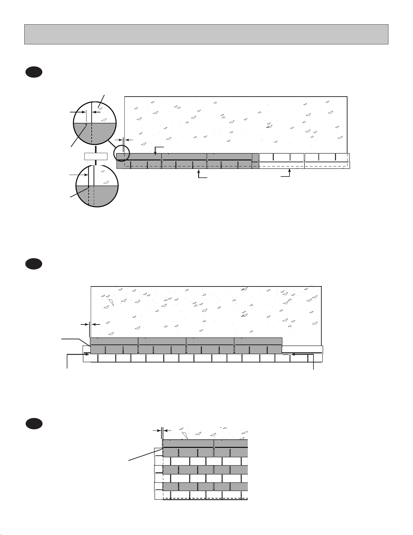
84
Beginning at front of shed, install rst row of shingles with notch at 1" past roof edge or ush with drip edge.
2
2
FRONT OF
SHED
BACK OF
SHED
BACK OF
SHED
Notch
- or -
Drip Edge
Notch
Roof Deck
1"
(2,5 cm)
Flush with starter row.
Flush with starter row.
Continue installing rows of
shingles by staggering at front.
4
SHINGLES
continued...
Install second row of shingles ush at top of rst row's rain slots. Ensure 1" overhang or ush to drip edge at front,
stagger each row.
3
1"
(2,5 cm)
1"
(2,5 cm)
FRONT OF
SHED
FRONT OF SHED
Flush with rain slots.
Flush with rain slots.
Notch
Notch
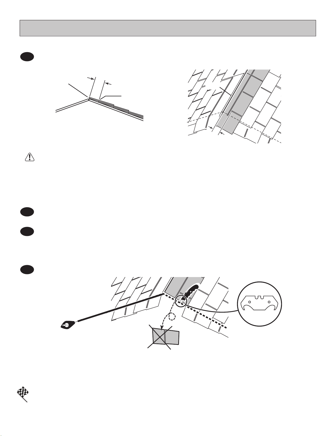
85
You have nished shingling your roof. Proceed to capping the ridge.
FINISH
Continue installing rows of shingles to the peak. At the peak make sure there is a maximum of 5" or less to the rain slot, as
shown below. If shingles overlap at ridge cut to peak with a utility knife.
Repeat steps 1 - 5 to shingle the opposite side of your roof. Trim shingles at ridge.
Once both sides are shingled you need to trim ends. Strike a chalk line 1" from edge.
Using your shingle hooked blade carefully cut shingles along chalk line.
5
6
7
8
SHINGLES
continued...
• If more than 5" to rain slot you must install another row of shingles.
5"
(12,7 cm)
or less.
5"
(12,7 cm) MAX.
Top of rain slot.
Cut Off.
CUT
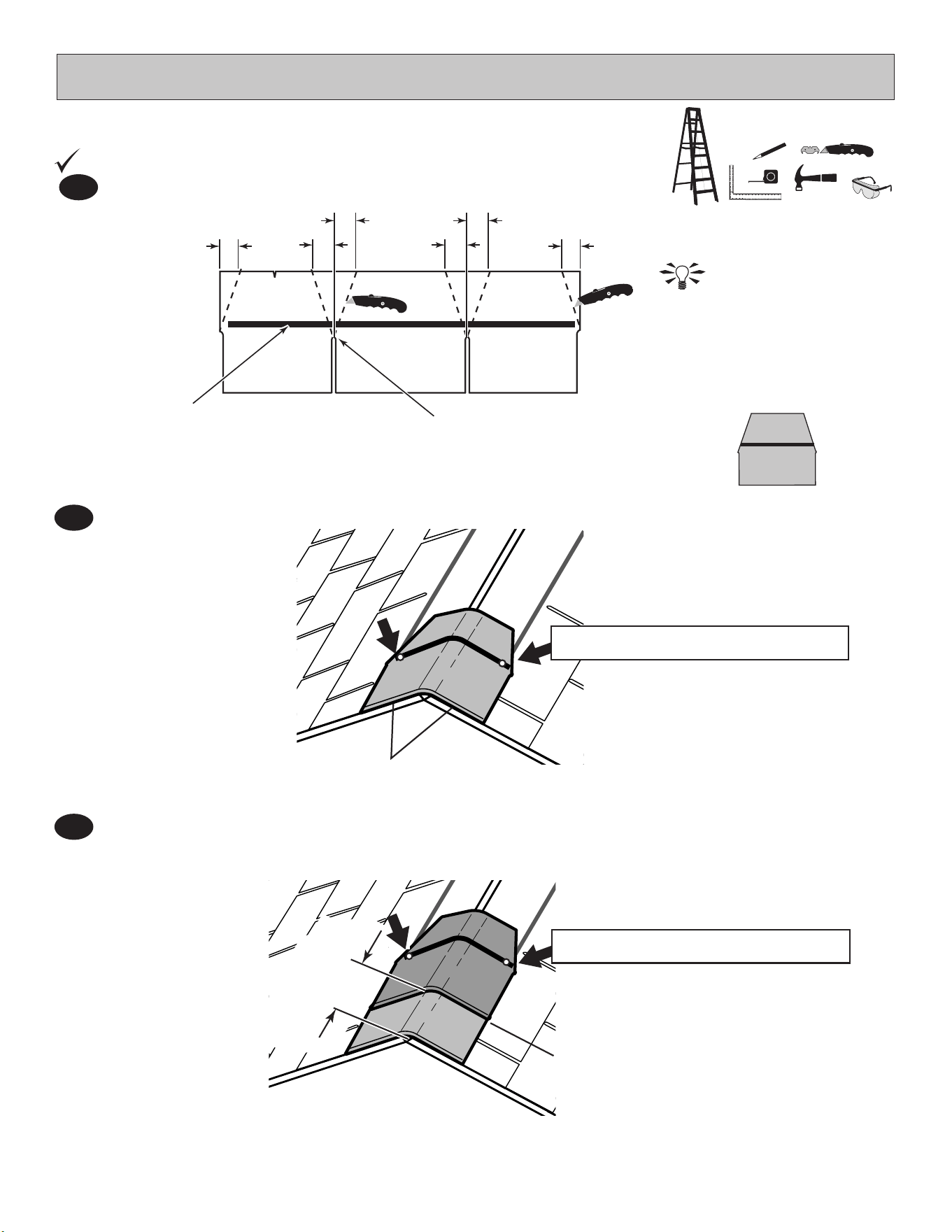
86
SHINGLES - RIDGE CAP
• You will nish off the top of the roof with a ridge cap made from shingles.
Note: • You will need about 32 - 34 cut pieces.
Cut shingles into THREE pieces. Hint: Use cut-off pieces rst.
Score shingle,
then snap-off angled cut.
Install rst ridge cap ush to shingles at front, as shown.
Install second ridge cap 5" back, as shown.
2
3
BEGIN
1
2"
(5 cm)
2"
(5 cm)
2"
(5 cm)
2"
(5 cm)
2"
(5 cm)
2"
(5 cm
Top of slot.
Weather Seal
Flush
(1) Nail per side through weather seal.
(1) Nail per side through weather seal.
5"
12,7 cm
FRONT OF
SHED
FRONT OF
SHED
Flush
32 to 34
Pieces
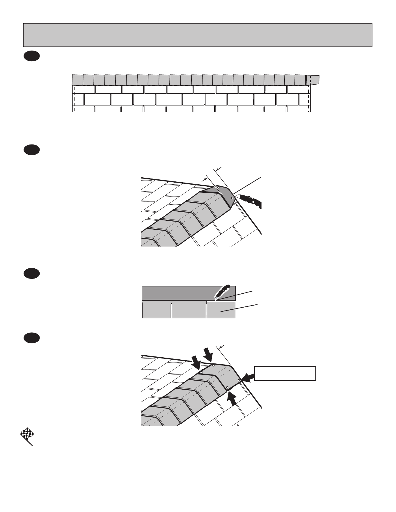
87
SHINGLES - RIDGE CAP
continued...
Continue installing ridge cap to back of roof.
Make sure there is 4" between the shingle-color and edge of shingles.
When you have 4" minimum of shingle color cut one piece to cap your roof.
Install ush to shingles.
4
5
6
7
(2) Nails per side.
You have nished your ridge cap.
FINISH
Cut at top of rain slot.
Flush to shingles
Trim cap off ush to shingles
Cap
4"
(10 cm)

88
LIMITED CONDITIONAL WARRANTY*
Backyard Storage Solutions, LLC warrants the following:
1. Every product is warranted from defects in workmanship and manufacturing for 1 year.
2. All accessories, hardware and metal components are warranted for 2 years.
3. All Oriented Strand Board (OSB) is warranted for 2 years
4.
Siding and Trim is warranted for 15 years.
5. Solar Shed windows are warranted for 1 year.
6. Cedar lumber is warranted for 15 years.
7. Preserved Pine is warranted for 10 years.
Backyard Storage Solutions, LLC will repair, replace or pay for the affected part. In no event shall Backyard Storage Solutions, LLC
pay the cost of labor or installation or any other costs related thereto. All warranties are from date of purchase. If a cash refund is paid
on an affected part, it will be prorated from the date of purchase.
CONDITIONS
The warranty is effective only when:
1. The unit has been erected in accordance with the assembly instructions.
2. The unit has been properly shingled and painted or stained and reasonably and regularly maintained thereafter.
3. The failure occurs when the unit is owned by the original purchaser.
4. Backyard Storage Solutions, LLC has received the warranty registration card within thirty (30) days of purchase and
notification of the failure in writing within the warranty period specified above.
5. Backyard Storage Solutions, LLC has had reasonable opportunity during the sixty (60) days following receipt of notification to
inspect and verify the failure prior to commencement of any repair work.
REQUIREMENTS
Storage Buildings
To validate your warranty, it is necessary to properly maintain your Backyard Storage Solutions, LLC unit; shingle the roof and paint or
solid-colored stain the siding using quality, 100% acrylic latex exterior product with a minimum of two (2) coats within thirty (30) days of
assembly; caulk above all doors and all horizontal and vertical trim boards; paint and seal all exposed edges, sides and faces of
siding/trim and OSB siding to include all exterior walls and all sides and all edges of doors.
Gazebos & Pergolas
To validate your warranty, it is necessary to properly maintain your Backyard Storage Solutions, LLC unit. This includes treating all of
the exposed cedar and pine surfaces on your gazebo or pergola structure with an exterior grade wood preservative, an exterior
oil-based semi-transparent stain, an acrylic latex exterior paint or an acrylic latex solid color exterior stain within 30 days of assembly
and as needed thereafter to maintain your warranty.
Keep vegetation trimmed away from building and make sure siding panels and trim do not come in contact with masonry or cement.
The minimum ground clearance for siding must be one half inch (½ inch) from concrete slab or two and one half inches (2 ½”) from the
ground when building is erected or constructed on a treated wood floor kit. Water from sprinklers must be kept off unit. In no event will
Backyard Storage Solutions, LLC be responsible for any indirect, incidental, consequential or special damages nor for failure(s) that
are caused by events, acts or omissions beyond our control including, but not limited to, misuse or improper assembly, improper
maintenance (which eventually leads to rot or decay) and acts of God. Backyard Storage Solutions, LLC will not be held responsible for
any labor costs incurred to construct your unit.
This warranty gives you certain specific rights that vary from state to state.
CLAIM PROCEDURE
To make a claim under this warranty, you can either call 1-888-827-9056 or email: [email protected].
Please have ready the information below when you call or include the information in your email:
1. The model and size of the product.
2. A list of the part(s) for which the claim is made.
3. Proof of purchase of the Backyard Storage Solutions, LLC item, as shown on the original invoice.
4. Run code: found on exterior product label or assembly instructions enclosed in the product package.
All other inquiries can be mailed to:
Backyard Storage Solutions, LLC
Attn: Customer Service
1000 Ternes
Monroe, MI 48162
*WARRANTY TERMS MAY VARY OUTSIDE THE U.S.A.
IMPORTANT: This is your warranty certificate.
YDL LDR: 2/3/2016
WARRANTY REGISTRATION
Please complete your warranty registration to properly validate your warranty.
Register your product online at:www.OnlineWarranty.net.
