

AXIS Perimeter Defender
Table of Contents
About AXIS Perimeter Defender . . . . . . . . . . . . . . . . . . . . . . . . . . . . . . . . 3
How does it work? . . . . . . . . . . . . . . . . . . . . . . . . . . . . . . . . . . . . . . . . . . . . . . . 4
The user interface . . . . . . . . . . . . . . . . . . . . . . . . . . . . . . . . . . . . . . . . . . . . . . . 6
CPU load . . . . . . . . . . . . . . . . . . . . . . . . . . . . . . . . . . . . . . . . . . . . . . . . . . . . . . 11
Show a demo of AXIS Perimeter Defender . . . . . . . . . . . . . . . . . . . . . . . . . . . . 11
Get started . . . . . . . . . . . . . . . . . . . . . . . . . . . . . . . . . . . . . . . . . . . . . . . . 12
Get started with AXIS Perimeter Defender . . . . . . . . . . . . . . . . . . . . . . . . . . . . 12
Get started with AXIS Perimeter Defender PTZ Autotracking . . . . . . . . . . . . . 12
Mount the camera . . . . . . . . . . . . . . . . . . . . . . . . . . . . . . . . . . . . . . . . . . . . . . 12
Mount the PTZ camera . . . . . . . . . . . . . . . . . . . . . . . . . . . . . . . . . . . . . . . . . . . 14
Install software on computer . . . . . . . . . . . . . . . . . . . . . . . . . . . . . . . . . . . . . . 15
Add devices . . . . . . . . . . . . . . . . . . . . . . . . . . . . . . . . . . . . . . . . . . . . . . . . . . . . 16
Install software on devices . . . . . . . . . . . . . . . . . . . . . . . . . . . . . . . . . . . . . . . . 17
Calibrate - AXIS Perimeter Defender . . . . . . . . . . . . . . . . . . . . . . . . . . . . . . . . 18
Calibrate - PTZ Autotracking . . . . . . . . . . . . . . . . . . . . . . . . . . . . . . . . . . . . . . 24
Dene scenarios . . . . . . . . . . . . . . . . . . . . . . . . . . . . . . . . . . . . . . . . . . . . . . . . 25
Pair the cameras - PTZ Autotracking . . . . . . . . . . . . . . . . . . . . . . . . . . . . . . . . 27
Dene outputs . . . . . . . . . . . . . . . . . . . . . . . . . . . . . . . . . . . . . . . . . . . . . . . . . . 29
Advanced conguration . . . . . . . . . . . . . . . . . . . . . . . . . . . . . . . . . . . . . . 31
Outputs . . . . . . . . . . . . . . . . . . . . . . . . . . . . . . . . . . . . . . . . . . . . . . . . . . . . . . . 31
Metadata . . . . . . . . . . . . . . . . . . . . . . . . . . . . . . . . . . . . . . . . . . . . . . . . . . . . . . 36
VMS integration . . . . . . . . . . . . . . . . . . . . . . . . . . . . . . . . . . . . . . . . . . . . . . . . 36
Troubleshooting . . . . . . . . . . . . . . . . . . . . . . . . . . . . . . . . . . . . . . . . . . . . 38
Update to the latest version . . . . . . . . . . . . . . . . . . . . . . . . . . . . . . . . . . . . . . . 38
Upgrade camera rmware . . . . . . . . . . . . . . . . . . . . . . . . . . . . . . . . . . . . . . . . 38
Installation troubleshooting . . . . . . . . . . . . . . . . . . . . . . . . . . . . . . . . . . . . . . . 39
Conguration troubleshooting . . . . . . . . . . . . . . . . . . . . . . . . . . . . . . . . . . . . . 39
Operation troubleshooting . . . . . . . . . . . . . . . . . . . . . . . . . . . . . . . . . . . . . . . . 40
Performance troubleshooting . . . . . . . . . . . . . . . . . . . . . . . . . . . . . . . . . . . . . . 41
2
AXIS Perimeter Defender
About AXIS Perimeter Defender
About AXIS Perimeter Defender
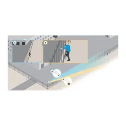
AXIS Perimeter Defender is an application for perimeter surveillance and protection. It is ideal for high-security perimeter protection
where there is a need to strengthen the physical access control system with reliable intrusion detection.
AXIS Perimeter Defender is primarily designed for so-called sterile zone protection, for example along a fence marking a boundary.
The term sterile zone refers to an area where people are not supposed to be.
Use AXIS Perimeter Defender in an indoor or outdoor environment to:
• Detect moving persons.
• Detect moving vehicles, without discriminating between vehicle types.
Note
AXIS Perimeter Defender is optimized for outdoor detection. You can use it in an indoor environment if the prerequisites are
met. If the camera is mounted too low, or if there are too many objects in the eld of view, performance is degraded.
VMS
3
AXIS Perimeter Defender
About AXIS Perimeter Defender
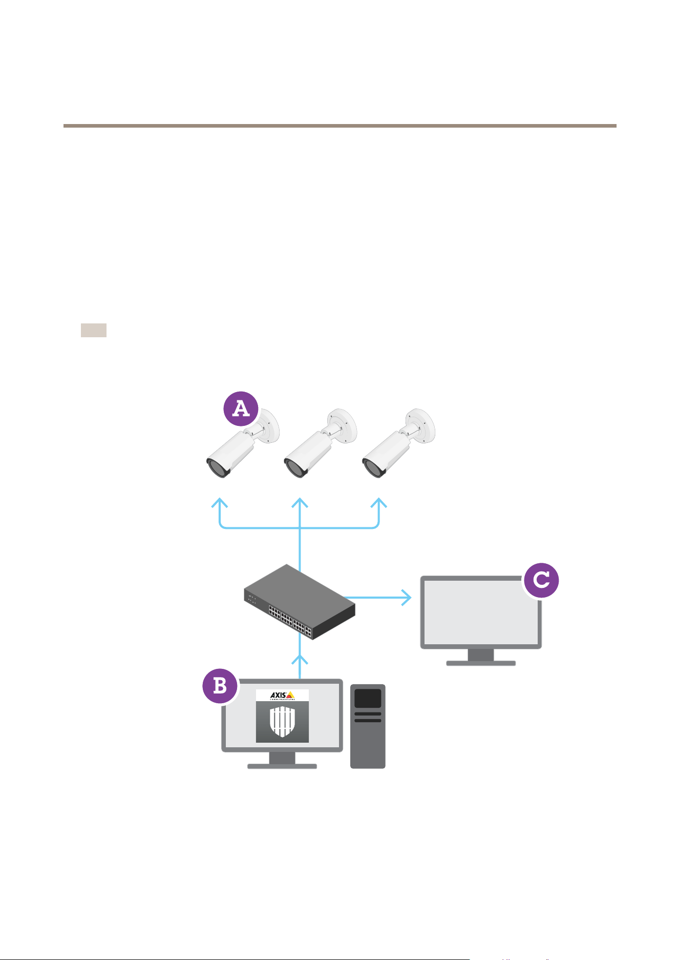
AXIS Perimeter Defender consists of a desktop interface (B), from where you install and set up the application on the cameras (A). You
can then congure the system to send alarms to the Video Management Software (C).
AXIS Perimeter Defender PTZ Autotracking is a plugin to the AXIS Perimeter Defender application, using the same desktop interface.
With the plugin, you pair a xed visual or thermal camera with an Axis Q-line PTZ camera. You can then maintain continuous
detection coverage of a scene with the xed camera while the PTZ camera automatically tracks and gives you closer views
of detected objects.
AXIS Perimeter Defender offers the following types of detection scenarios:
• Intrusion: triggers an alarm when a person or a vehicle enters a zone dened on the ground (from any direction
and with any trajectory).
• Loitering: triggers an alarm when a person or a vehicle remains in a zone dened on the ground for more than
a predened number of seconds.
• Zone-crossing: triggers an alarm when a person or a vehicle passes through two or more zones dened on the ground in
a given sequence.
• Conditional: triggers an alarm when a person or a vehicle enters a zone dened on the ground without rst passing
through another zone or zones dened on the ground.
How does it work?
Detection of objects
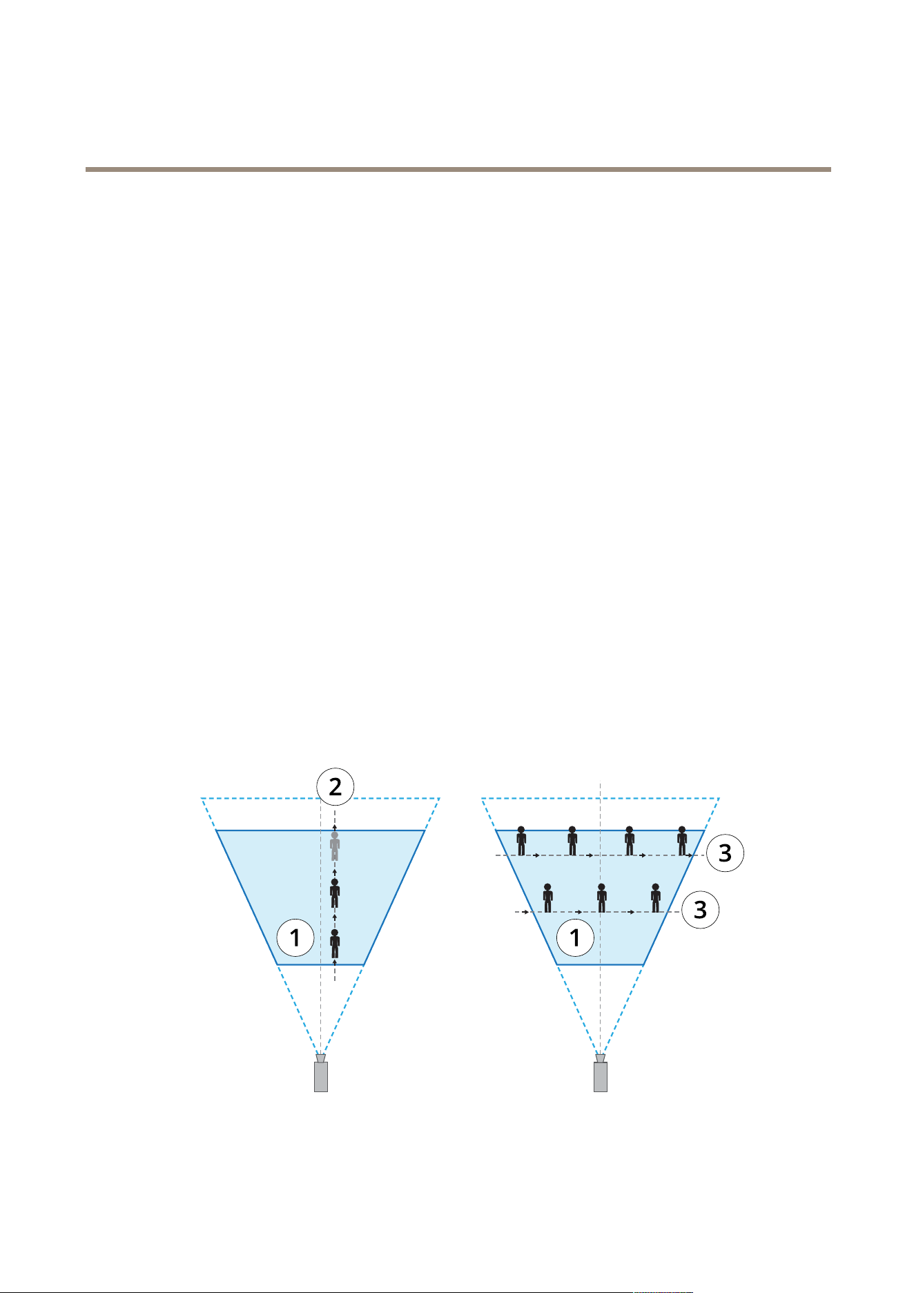
AXIS Perimeter Defender can detect moving persons or vehicles. To be detected:
• a person or vehicle must be entirely visible in the detection zone for at least three seconds.
• a vehicle can be up to 12 meters (39.4 feet) long.
• persons or vehicles must be visibly moving as seen from the camera’s point of view. This means that the detection
rate of a person approaching or walking away from the camera in a straight line is lower than for a person walking
perpendicular to the camera's eld of view.
1
Detection zone
2
A person walks away from the camera
3
Persons walk perpendicular to the camera’s eld of view
4
AXIS Perimeter Defender
About AXIS Perimeter Defender
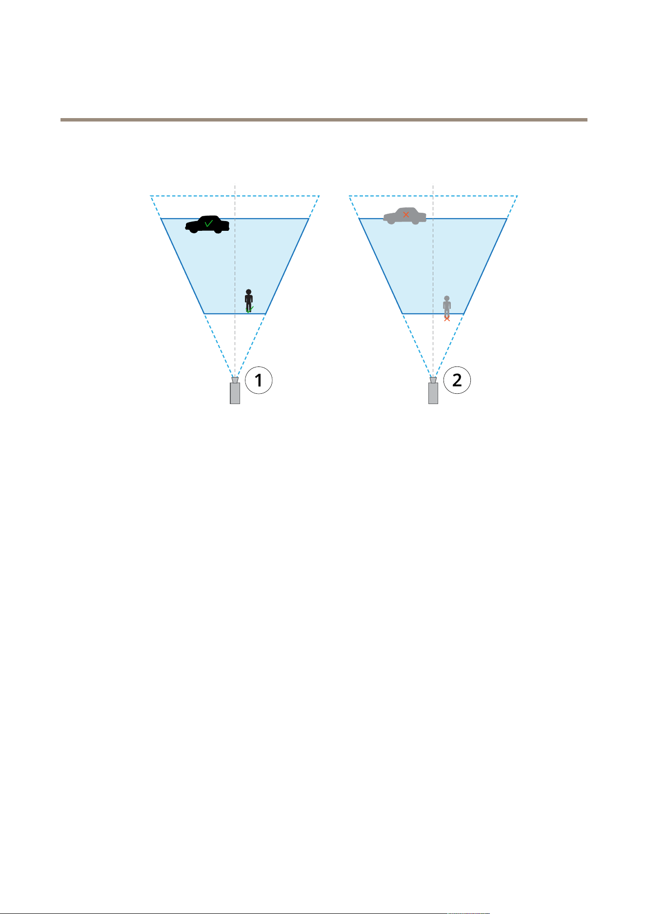
• the point of detection must be inside the detection zone. The point of detection of a person is at its feet, and of a
vehicle it is at its center.
1
Point of detection inside the detection zone
2
Point of detection outside the detection zone
Once detected, AXIS Perimeter Defender continues to track the person or vehicle even if it’s partially hidden, for example when the
body of a person is hidden behind a car and only the person’s head is visible.
If a detected person or vehicle stops moving for a few seconds, AXIS Perimeter Defender stops tracking it. If they start moving
again after less than 15 seconds, the application continues to track them. If the person was in a zone-crossing zone, there is no
guarantee that the scenario triggers correctly.
How does PTZ Autotracking work?
In AXIS Perimeter Defender PTZ Autotracking, a xed camera and a PTZ camera work together. When the xed camera detects
moving people or vehicles, it sends the location data of the objects to the paired PTZ camera. This makes it possible for the PTZ
camera to automatically:
• follow the objects, and
• adjust the zoom level to keep all objects in view
as long as the objects are within the eld of view of the xed camera.
Conditions where detections can be delayed or missed
• Fog
• Direct light shining on the camera
• Inadequate light
• Overly noisy image
Situations that can trigger false alarms
• Partially hidden people or vehicles. For example, a small van that appears from behind a wall can look like a person since
the visible part is high and narrow.
5
AXIS Perimeter Defender
About AXIS Perimeter Defender
• Insects on the camera lens. Note that day-and-night cameras with infrared spots attract insects and spiders.
• A combination of car headlights and heavy rain.
• Human-size animals, especially if the additional approach types crouch/crawl or log roll have been selected in
the Scenarios tab.
• Strong light causing shadows.
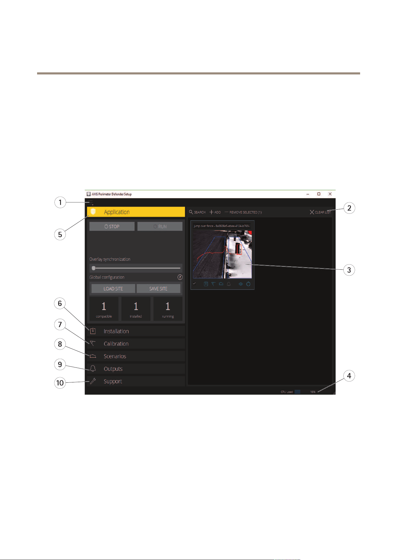
The user interface
The AXIS Perimeter Defender interface lets you for example calibrate devices, set up scenarios and perform actions for multiple
devices. Remote setup allows for conguration from wherever there is a network connection.
1
Interface settings on page 6
2
Handle devices. See Add devices on page 16.
3
Live view on page 7
4
CPU load indicator. See CPU load on page 11 .
5
Application tab on page 9
6
Installation tab on page 9
7
Calibration tab on page 9
8
Scenarios tab on page 9
9
Output tab on page 10
10
Support tab on page 10
Interface settings
The interface settings menu contains:
6
AXIS Perimeter Defender
About AXIS Perimeter Defender
Folder settings -
Device conguration path: Select where to store temporary les and calibration video.
Site conguration path: Select where to store conguration les from load paths.
Camera passwords - Look at used passwords and add new password. Passwords are not stored once the user exits the application.
Manage demo clips packages - Import or remove demo clips.
Enable full frame rate mode - Change the frame rate in the live view. See CPU load on page 11 .
Display feet and inches - Change between metric and imperial units.
Change language - Change the language in the application.
About - See the version number of AXIS Perimeter Defender Setup.
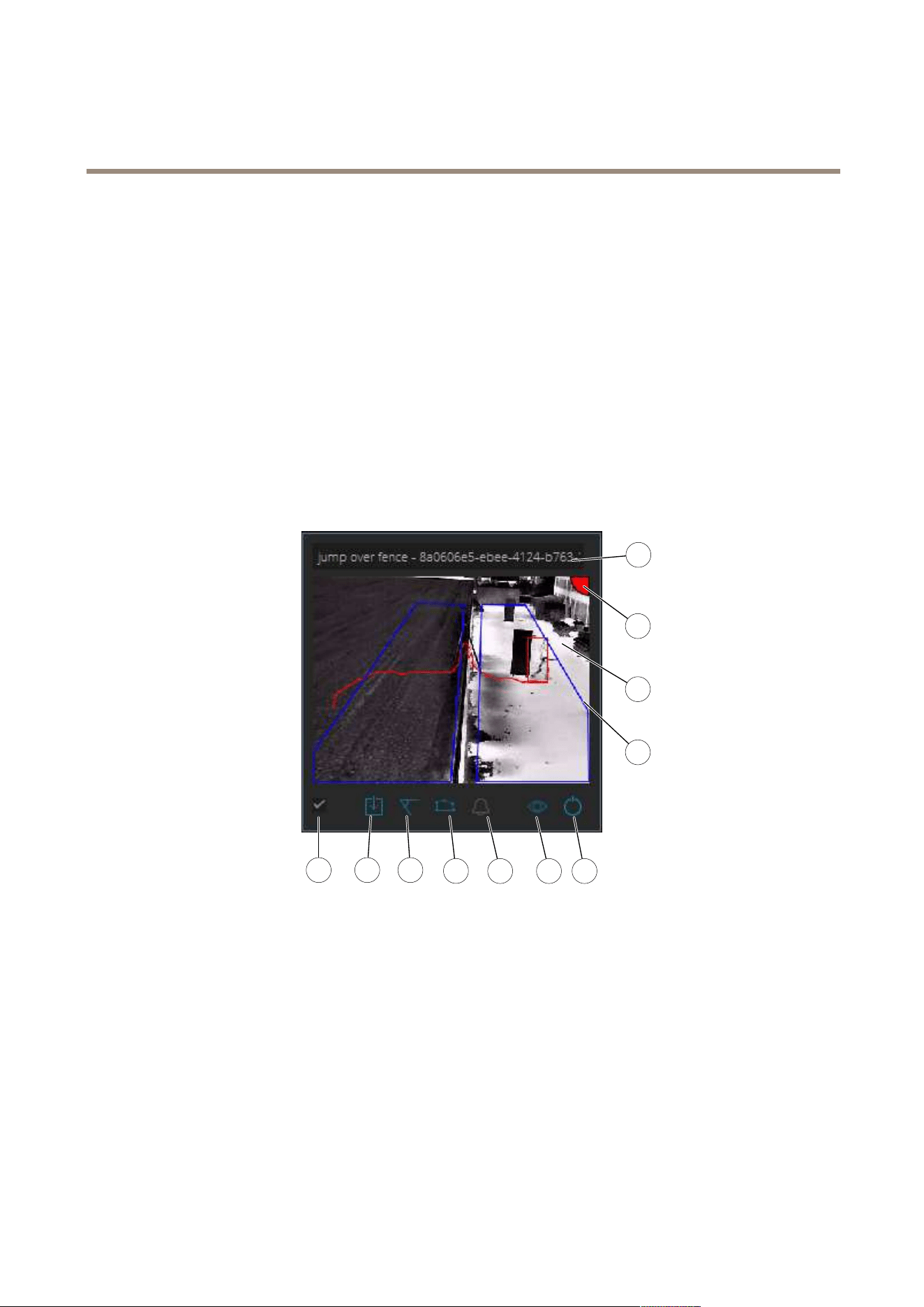
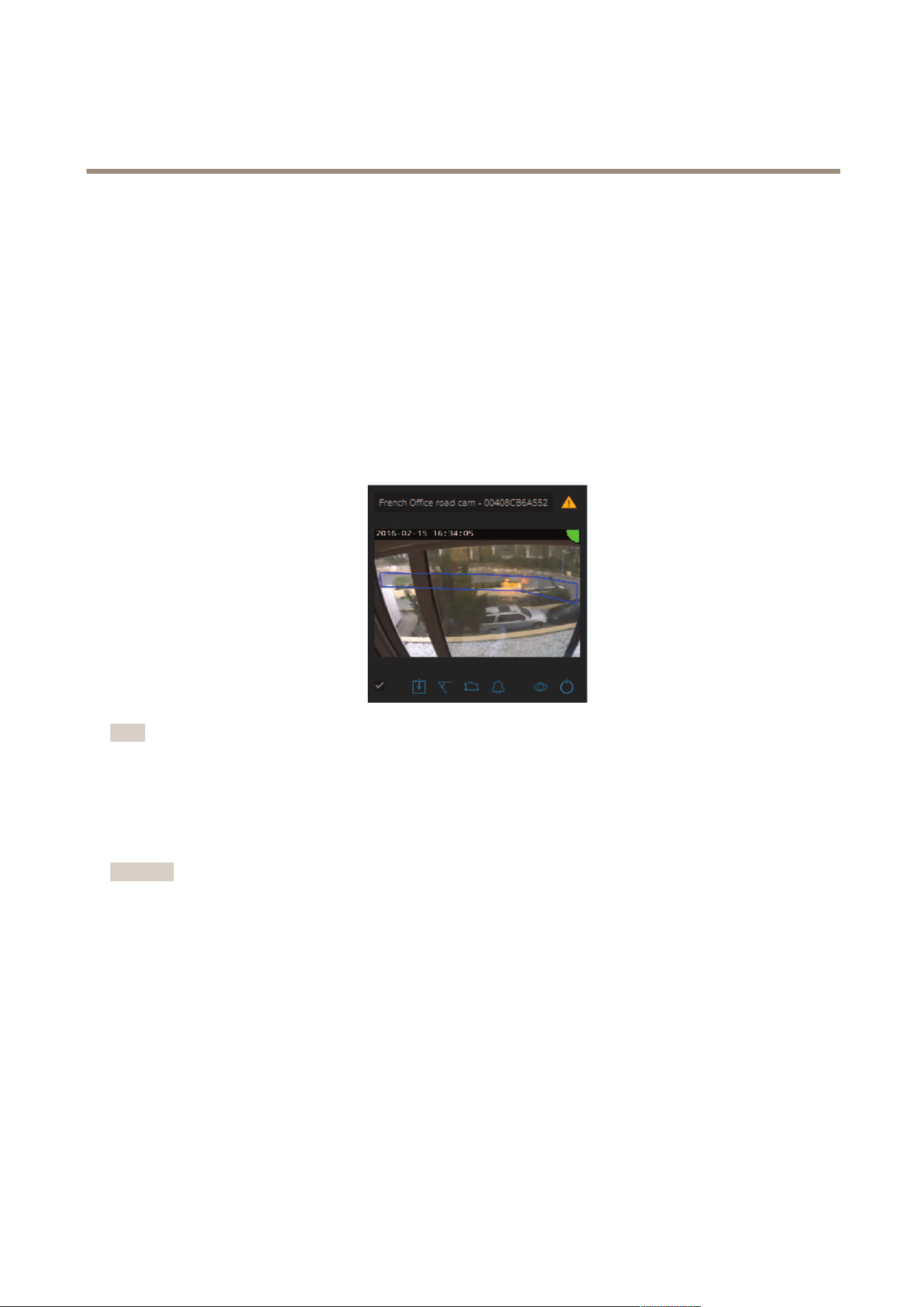
Live view
Each connected device gets a live view in the main interface. The live view provides the device status and quick access to the
main functions.
1
2
3
4
5 6 7
8
9 10 11
1. Device name - Click to edit the device name. It always includes the IP address and MAC number of the device. Hover the
name to show the aspect ratio used for analysis, which provides maximum eld of view coverage, and to see if the device is on a
remote connection.
2. Live image - In the overview mode, the frame rate is 1 fps. Double-click to maximize the image and increase the frame rate to 8 fps.
3. Alarm status - The alarm status is only visible if the overlay is active and AXIS Perimeter Defender is installed, congured,
and running.
• Grey means that the alarm functionality is not active or that the conguration settings are loading.
• Green means that the alarm functionality is active.
• Red means that an alarm has been triggered.
4. Detection zones - The detection zones are only visible if the overlay is active and AXIS Perimeter Defender is installed, congured,
and running.
7
AXIS Perimeter Defender
About AXIS Perimeter Defender
5. Selection checkbox - To be able to select multiple devices, use this checkbox.
6. Installation status and quick access button - Hover to show the version of AXIS Perimeter Defender installed on the device. If the
icon is replaced by
, this means a more recent version is available. Click to open the Installation tab for the device.
• Grey means that the device is not installed.
• Orange means that the device is installed, but does not have a valid license.
• Blue means the device is installed with a valid license.
7. Calibration status and quick access button - Click to open the Calibration tab for the device. Grey means that the device
is not calibrated. Blue means that the device is calibrated.
8. Scenarios status and quick access button - Click to open the Scenarios tab for the device. Grey means that no scenario
is dened. Blue means that at least one scenario is dened.
9. Outputs status and quick access button - Click to open the Output tab for the device. Grey means that no outputs are congured.
Blue means that at least one output is congured.
10. Overlay status and toggle button - Click to toggle overlay on and off. Grey means that the overlay is inactive. Blue means
that the overlay is active. The overlay is shown as a bounding-box around detected objects as well as a “snail-trail” displaying
trajectory of objects.
11. Running status and toggle button - Click to run/stop the application on the device. Grey means that the application is
stopped. Blue means that it is running.
Note
Overlay is only available if a direct connection from the device to the user’s computer is available, that is if no rewalls or
similar prevent connection to the overlay port on the device.
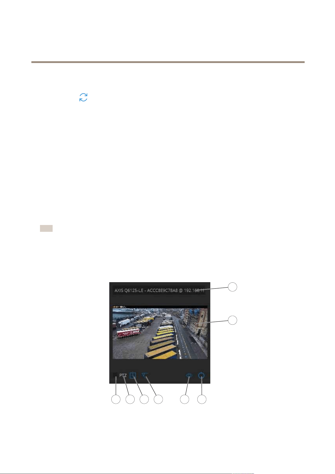
Live view - PTZ Autotracking
The live view for devices that have AXIS Perimeter Defender PTZ Autotracking installed differs slightly from the regular live view.
1
2
3 4 5 6 7 8
1
Device name
2
Live image
8

AXIS Perimeter Defender
About AXIS Perimeter Defender
3
Selection checkbox
4
Indicates that the device uses AXIS Perimeter Defender PTZ Autotracking
5
Installation status and quick access button
6
Calibration status and quick access button
7
Overlay status and toggle button
8
Running status and toggle button
Application tab
• Run – Start the analytics on the selected device(s).
• Stop – Stop the analytics on the selected device(s).
• Load Site – Load a previously saved site, i.e. devices and their respective conguration les
• Save Site – Save the current site, i.e. save all the device information and their respective congurations les
• Overlay synchronization - Control over AXIS Perimeter Defender metadata overlay synchronization. This slider controls
delay between metadata overlay and received images to compensate for slower image streaming compared to metadata.
Slider value indicates the delay set for the current selected camera. If more than one camera are connected, the value
indicated is that of the rst selected camera. Changing the slider value changes delay for all the selected cameras.
You can also see the number of compatible devices added, the total number of devices with AXIS Perimeter Defender installed and the
number of devices on which analytics is running.
Installation tab
• Application: Install — Install the application on the selected device(s).
• Application: Uninstall — Uninstall the application on the selected device(s).
• Licence: Install — Install licence on the selected device(s).
Calibration tab
• Automatic — Perform an automatic calibration of the selected device(s).
• Manual — Perform a manual calibration of the selected device(s).
Scenarios tab
• Global parameters — apply to all scenarios.
• Advanced scenarios — create intrusion, loitering, zone-crossing and conditional scenarios.
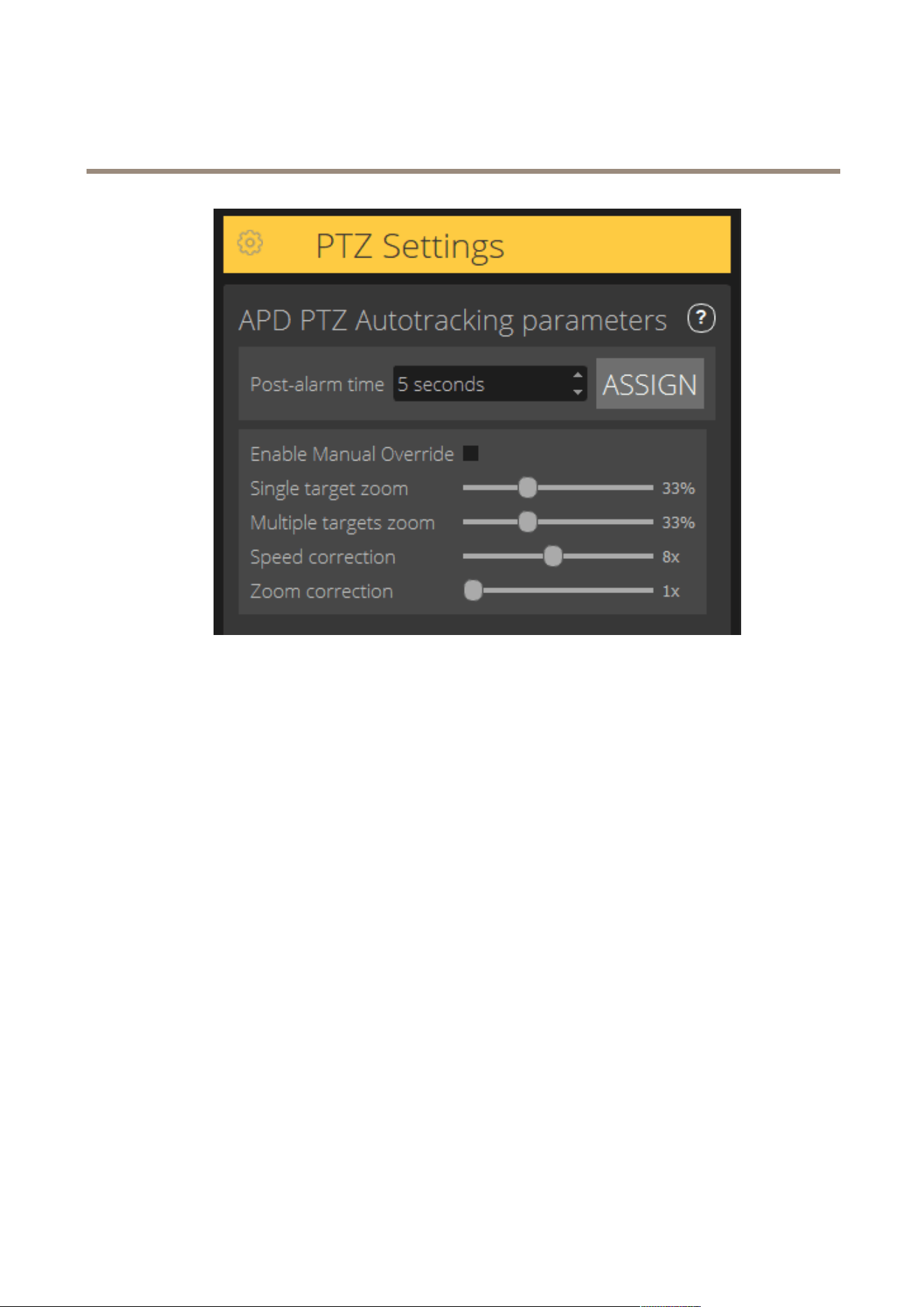
PTZ settings tab
Note
This tab is only shown if you have the plugin AXIS Perimeter Defender PTZ Autotracking.
9
AXIS Perimeter Defender
About AXIS Perimeter Defender
• Post-alarm time – Dene the time before the PTZ camera returns to its home position, once the tracked object has
disappeared from view.
• Enable manual override – When checked, the operator can take control of the PTZ camera with a joystick, in the VMS, or
in the camera’s webpage.
• Single target zoom – Adjust the zoom level for tracking a single target. A higher value gives better possibilities for
identication, but also increases the risk of losing rapidly moving objects.
• Multiple targets zoom – Adjust the zoom level for tracking multiple targets.
• Speed correction – Adjust the tracking speed to keep rapidly moving objects centered in the PTZ camera image. Note that
a high value can lead to tracking instability.
• Zoom correction – A higher value increases the zoom out for objects that are close to the edge of the PTZ camera’s
eld of view.
Output tab
• Congure — Open the device’s webpage to create and congure alarms.
• Test alarm — Test the alarm congured for the device.
• Post-alarm time: Assign — Set the post-alarm time.
Support tab
• Load — Load backed-up conguration for selected device(s). This is especially useful to quickly restore after a device failure
or accidental uninstallation. The conguration includes:
- License
- Parameters
10

AXIS Perimeter Defender
About AXIS Perimeter Defender
- Calibration and scenarios
- Calibration video
• Save — Create a backup of the selected device(s)’ conguration.
• Clear — Erase calibration and scenarios from the selected device(s). This is useful if the cameras have moved, as calibration
and detection zones are then no longer valid.
• View application log — View the AXIS Perimeter Defender internal log.
• Export support log — Generate a support le that contains detailed information. Always include this le with a support
request.
CPU load
The CPU load indicator indicates current computer CPU load in real-time. Too high CPU load could result in an unresponsive computer
or application. Make sure to close other applications when you use AXIS Perimeter Defender Setup to maximize your CPU allocation.
If the CPU load is too high and you try to add a device, the system issues a warning.
Added devices take up CPU resources from the host computer to decode video streams from the camera and display them. To limit the
impact on the host computer, video streams from added devices display at a reduced frame rate (approximately 1 fps) by default.
Normal frame rate (approximately 8 fps) is restored when streams are maximized or during the calibration process.
Important
Enable full frame rate mode can lead to an unresponsive interface if you connect to a large number of cameras or when you
use a low power computer.
Show a demo of AXIS Perimeter Defender
For demo purposes, AXIS Perimeter Defender and AXIS Perimeter Defender PTZ Autotracking comes pre-installed with a few demo
clips that can be used to demonstrate the analytics without the need for an active, installed camera. The demo clips show the kind of
detection and autotracking results that can be expected in different environments.
1. Go to Application > Add > Demo Clips and do one or more of the following:
- Filter demo clips according to their type.
- Select at least one demo clip.
2. To add the demo clips, click Add Selected Demo Clips.
Once added, the demo clips appear as standard video streams in the interface. Calibration is available and analytics already activated
so that the user immediately sees analytics and autotracking results on the video stream. Analytics and autotracking can be stopped
or started by clicking the running status in the live view or the Run or Stop buttons on the left pane.
Calibration and pairing can be modied and redone. Similarly, detection scenarios can be added, removed and modied.
The Support tab on the left pane has a Clear button that lets you revert calibration and scenarios to the original values. It is not
possible to completely remove the calibration.
11

AXIS Perimeter Defender
Get started
Get started
The installation process for AXIS Perimeter Defender and AXIS Perimeter Defender PTZ Autotracking differs slightly.
Get started with AXIS Perimeter Defender
You need to go through the following steps to get your site up and running with AXIS Perimeter Defender:
1. Mount the camera. See Mount the camera on page 12.
2. Download and install the software on your computer. See Install software on computer on page 15.
3. Connect to your devices. See Add devices on page 16.
4. Install AXIS Perimeter Defender on each device. See Install software on devices on page 17.
5. Calibrate the devices. See Calibrate - AXIS Perimeter Defender on page 18.
6. Dene the rules for what should trigger alarms by adding scenarios. See Dene scenarios on page 25.
7. Set up alarms to be sent. See Dene outputs on page 29.
Get started with AXIS Perimeter Defender PTZ Autotracking
You need to go through the following steps to get your site up and running with AXIS Perimeter Defender PTZ Autotracking:
1. Mount the cameras. See Mount the camera on page 12 and Mount the PTZ camera on page 14.
2. Download and install the software on your computer. See Install software on computer on page 15.
3. Connect to your devices. See Add devices on page 16.
4. Install AXIS Perimeter Defender version 2.5.0 or later on the xed camera, and AXIS Perimeter Defender PTZ Autotracking
on the PTZ camera. See Install software on devices on page 17.
5. Calibrate the devices and set up scenarios. See Calibrate - PTZ Autotracking on page 24.
6. Pair the devices. See Pair the cameras - PTZ Autotracking on page 27.
7. Set up alarms to be sent. See Dene outputs on page 29.
Mount the camera
About the design tool
To specify the camera placement on site, we recommend that you use the Design tool for AXIS Perimeter Defender. It takes into
account both Axis cameras’ and AXIS Perimeter Defender requirements. The tool helps you decide:
• Camera mounting height
• Tilt angle
• Minimum detection distance
• Maximum detection distance
To download the tool, go to axis.com/products/axis-perimeter-defender
12
AXIS Perimeter Defender
Get started
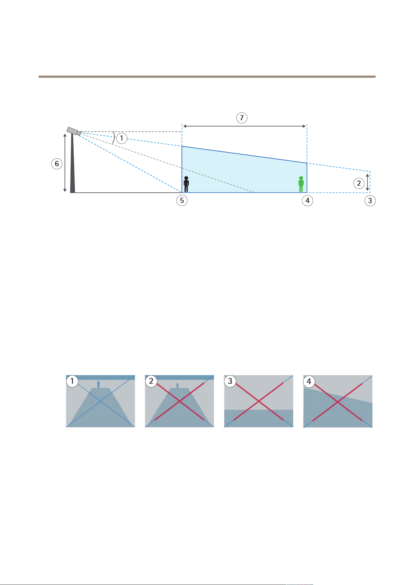
Recommendations when mounting the camera
An appropriately mounted camera.
1
Tilt
2
Field of view elevation
3
Field of view distance
4
Maximum detection distance
5
Minimum detection distance
6
Camera height
7
Detection zone
Object height at the maximum detection distance - For a standing person to be detected at the maximum detection distance, the
pixel height must be at least 5% of the total image height (3.5% for thermal cameras). For example, if the height of the visualized
image is 576 pixels, the height of a person standing at the end of the detection zone must be at least 28 pixels (20 pixels for thermal).
Object height at the minimum detection distance - For a standing person to be detected at the minimum detection distance, the
pixel height cannot be more than 60% of the total image height.
Tilt angle - The camera must be sufciently oriented towards the ground so that the center of the image is under the horizon
line. Mount the camera so that the minimum detection distance is longer than half of the camera’s mounting height (minimum
detection distance > camera mounting height / 2).
Roll angle - The roll angle of the camera must be nearly equal to zero.
1
Object height, tilt angle, and roll angle are suitable.
2
Object height at maximum detection distance is less than 5% of the image height (3.5% for thermal cameras).
3
The center of the image is above the horizon line.
4
The roll angle of the camera is not nearly equal to zero.
The maximum detection distance depends on:
• Camera type
• Camera lens. A higher focal range allows for a longer detection distance.
13

AXIS Perimeter Defender
Get started
• The minimum pixel size a human must cover in the image to be detected. The pixel height of a standing person must be at
least 5% of the image height for visual cameras and 3.5% for thermal cameras.
• Weather
• Lighting
• Camera load
When you mount the camera, consider:
• vibrations. The application tolerates small camera vibrations, but you get the best performance when the camera is
not subject to vibrations.
• eld of view. The eld of view of the camera must be xed.
Scene requirements
The detection zone needs to provide the following conditions:
• clear sight
• the ground must be at or with only a slight slope
• light does not trigger by movement
• for visual cameras, the level of illumination and image settings must be sufcient to provide enough contrast between
people and vehicles and the background.
- When you use an Axis day-and-night camera with articial lighting, we recommend at least 50 lux in the
entire detection zone.
- When you use external IR spots, we recommend a maximum detection distance of 80 m and that the range of
the IR spots is more than twice the maximum detection distance.
- When you use built-in IR lighting, the maximum detection distance is limited to max 20 m, depending on the
camera and the environment.
• for thermal cameras, there needs to be a high contrast between background and foreground
To optimize the detection performance, AXIS Perimeter Defender automatically learns the difference between day and night and
uses this information to ne-tune the detection algorithms. The ne-tuning takes about 24 hours, which means optimal detection
during both day and night is achieved after running the application for that time.
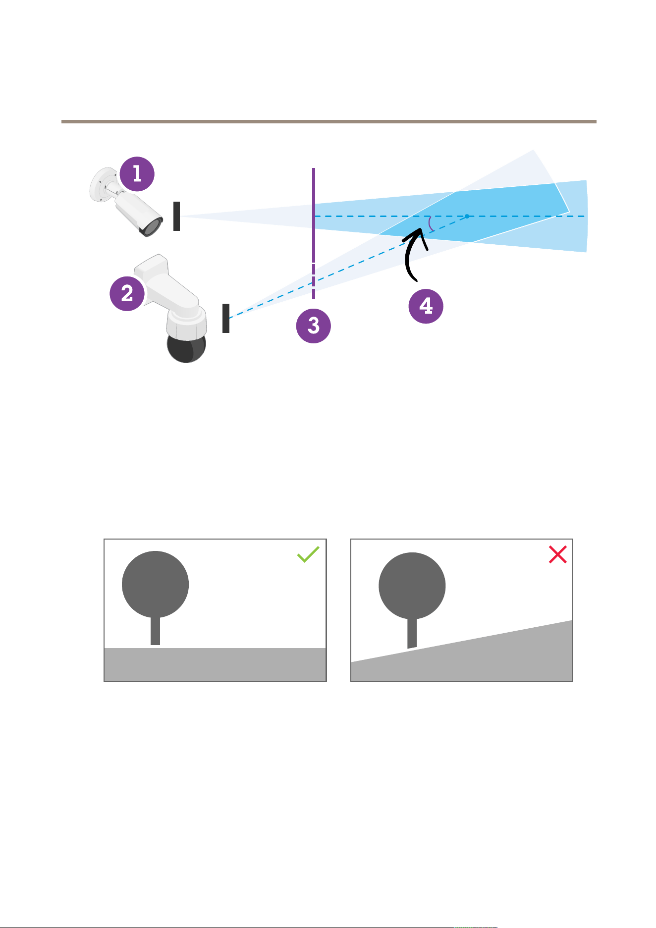
Mount the PTZ camera
This chapter describes how to mount the PTZ camera in relation to the xed camera. For instructions on how to mount the xed
camera, see Mount the camera on page 12.
14
AXIS Perimeter Defender
Get started
1
Fixed network camera
2
PTZ network camera
3
Minimum detection distance
4
Angle between the cameras
• The home preset position of the PTZ camera must cover more than 60% of the detection zone of the xed camera.
• To be tracked by the PTZ camera, a standing person must cover more than 4% of the image height of the PTZ camera.
• The PTZ camera must be placed before the minimum detection distance of the xed camera (C).
• The angle between the xed camera and the PTZ camera must be less than 30° (D).
• The ground must be at.
Install software on computer
1. Download the AXIS Perimeter Defender software from axis.com/products/axis-perimeter-defender
2. Install the software on your computer.
15
AXIS Perimeter Defender
Get started
Add devices
You can add devices to the AXIS Perimeter Defender application in three different ways:
• Automatically through a network scan. See Add devices automatically on page 16.
• Manually by specifying connection settings. See Add devices manually on page 16.
• Automatically by loading a previously saved site. See Load an existing site on page 17.
When you have added a device, you see a list of all other applications installed on the device. We recommend you to stop any
non-essential applications, as they use the camera’s CPU resources, which impacts the performance of AXIS Perimeter Defender
and may prevent correct installation.
If a device doesn't have enough CPU resources, for example because other applications are running, AXIS Perimeter Defender lowers
the frame rate. If the frame rate is below 5 frames per second, a yellow warning triangle is displayed next to the device name in the
live view. When you hover the triangle, the current frame rate is displayed.
Note
A frame rate below 5 fps can signicantly decrease the video analytic performance. This can result in both missed and
false detections.
For more information, see CPU load on page 11 .
Add devices automatically
Important
The search functionality does not work across networks, that is, AXIS Perimeter Defender Setup can only nd devices that are
connected to the same sub-network as that of the client running the software. To add devices connected to a different
sub-network, add them manually. The search functionality may also fail if the network routers or switches are congured
to lter multicast.
1. To scan the surrounding network for devices, go to Application and click Search.
When you do a search for the rst time and no passwords are available, a password dialog opens. Otherwise the available
password are used to connect to the devices.
2. Select devices and click Add selected devices.
If the password is correct, a static image shows up to guide the user when selecting devices.
Add devices manually
1. Go to Application and click Add.
16

AXIS Perimeter Defender
Get started
2. Enter the following:
- The device’s IP address or hostname.
- The device’s root password, since AXIS Perimeter Defender requires root access.
- The HTTP port used to connect. The default port is 80.
- An optional name for the device for easier recognition.
- If the device is on a remote network for which connection may be slow, check Device on remote network. Slow
connections that are not congured as remote can lead to non-working or bad calibrations.
Note
For remote connections the user must be able to connect to the device through HTTP. Make sure to setup the HTTP
port correctly. Remote conguration can fail when the connection doesn't have sufcient or stable bandwidth.
3. Click OK.
Note
If it doesn't work to add a camera by hostname, verify the network and DNS settings or add the device using its IP address.
Load an existing site
To load a previously saved site conguration:
1. Go to Application and click Load site.
2. Browse to select the site conguration le and click Open. The live view shows up automatically.
Install software on devices
You need to install AXIS Perimeter Defender on each device.
If you want to check which version of AXIS Perimeter Defender that is installed on a device, you can hover the Installation status in
the live view.
If a device doesn’t have AXIS Perimeter Defender installed, all icons in the live view are grey.
Install the software on a device
1. Go to Installation.
2. Select the device(s) where you want to install the application.
3. Select the latest available version of AXIS Perimeter Defender and click Install.
AXIS Perimeter Defender is now installed on the selected device(s) and starts automatically.
4. Browse for a licence and do one of the following:
- If you install on a single device: select the license le for the device.
- If you install on multiple devices: select the folder where license les are stored.
5. Click Install.
17

AXIS Perimeter Defender
Get started
Calibrate - AXIS Perimeter Defender
Calibration
For AXIS Perimeter Defender to correctly interpret the scene, you must calibrate all devices. During calibration, you introduce points
of reference that provide depth and height information for the processor. You also dene the zone of interest.
Calibration consists of two tasks:
1. Perform a calibration:
- automatic — recommended in most cases. See Perform an automatic calibration on page 18.
- manual — recommended if the automatic calibration fails on a camera, for ne tuning, or when it would be
impractical to conduct a walkthrough of the scene and there are objects of known height in the scene. An
example of this is a remote perimeter with a fence line consisting of a number of evenly spaced fence posts of a
consistent height. See Perform a manual calibration on page 22.
2. Verify the calibration results. See Verify the quality of the calibration on page 20.
To speed up the conguration of a large site, you can calibrate multiple devices simultaneously. You can perform the calibration
automatically or manually, just like for a single camera. Consider the following before you calibrate multiple devices simultaneously:
• The maximum number of devices you can install and congure simultaneously depends on the CPU power and the memory
available on your computer. Too many devices in AXIS Perimeter Defender Setup can cause crashes. When the CPU overload
warning appears, install and congure a subset of the devices using the save site-feature.
• Automatic calibration of multiple devices requires more CPU resources and RAM than for a single device. On low-spec
systems this might make the computer unresponsive for some time or lead to an application crash. In case of a crash,
videos captured are still available to be used afterwards for single camera calibration.
Note
• AXIS Perimeter Defender supports different image aspect ratios according to the maximum resolution provided by the
camera. As a result, you need to redo all previous calibrations if you change the resolution. However, if you change the
stream resolution in the camera’s webpage, you don’t need to re-calibrate.
• We recommend you to use the same image aspect ratio in AXIS Perimeter Defender and in the VMS, to make sure that the
displayed information ts the image content. To nd out the aspect ratio, hover the camera name in the live view.
• If a camera moves after calibration, you need to re-calibrate it for the analytic results to be correct.
Perform an automatic calibration
With automatic calibration, you can calibrate one or more cameras by letting a person walk through the surveillance scene. The
camera automatically gathers the information required to calibrate itself.
For a successful automatic calibration:
• Don’t calibrate when there are a lot of people in the eld of view.
• Don’t calibrate when there are a lot of vehicles passing in the eld of view.
• Don’t calibrate when there are other objects moving in the eld of view. For example trees or ags moving in the wind.
• Don’t calibrate a camera which has not been installed parallel to the ground.
• The person who walks through the scene must be able to cover the whole eld of view from front to back. If that is
not possible, it is better to switch to manual calibration.
• If the camera is on a remote network but not connected as remote, the person who walks through the scene must
walk for about 5 minutes to make sure enough images are captured. This is because the frame rate is usually lower
for devices on remote networks.
1. Go to Calibration.
18
AXIS Perimeter Defender
Get started
2. Select the device(s) you want to calibrate.
3. Click Automatic.
4. Set the recording start time. The capture should start at least 10 seconds before the person who walks through the
scene enters the eld of view.
5. Set the recording duration. Consider that:
- there needs to be enough time for the person to walk back and forth through the whole scene.
- the length of the video affects the calibration computation.
6. Enter the height (cm) of the person who walks though the scene and click Capture.
To reuse a previously captured video, click Use previous capture.
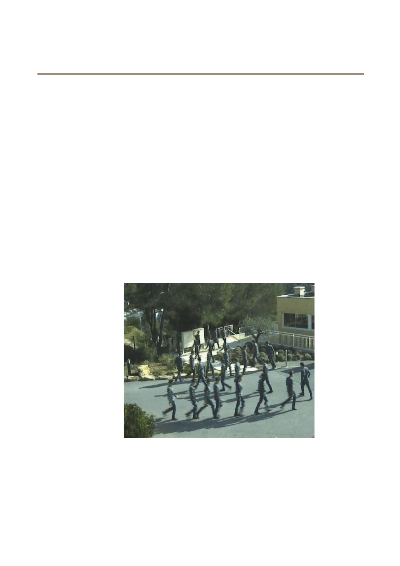
7. Let the person walk though the scene according to the following instructions:
- Walk in a zigzag path that covers as much as possible of the detection zone from front to back of the scene. We
recommend a V-shaped path across the eld of view.
- Remain almost always fully visible from head to feet in the eld of view.
- Walk slowly in straight lines.
- Keep an upright posture the whole time.
- Pause for 1-2 seconds before changing direction.
An example of a walk sequence.
8. Verify that automatic calibration has been successful by conrming that the person is detected accurately. See Verify the
quality of the calibration on page 20.
9. To save the calibration, click Accept.
To perform a new calibration, click New.
19
AXIS Perimeter Defender
Get started
To perform a manual calibration, click Manual.
When you have accepted the calibration, blue borders indicate the maximum detection zone. The maximum detection zone is the
largest area that can be monitored. Outside of this area, intruders might be detected but it is not guaranteed.
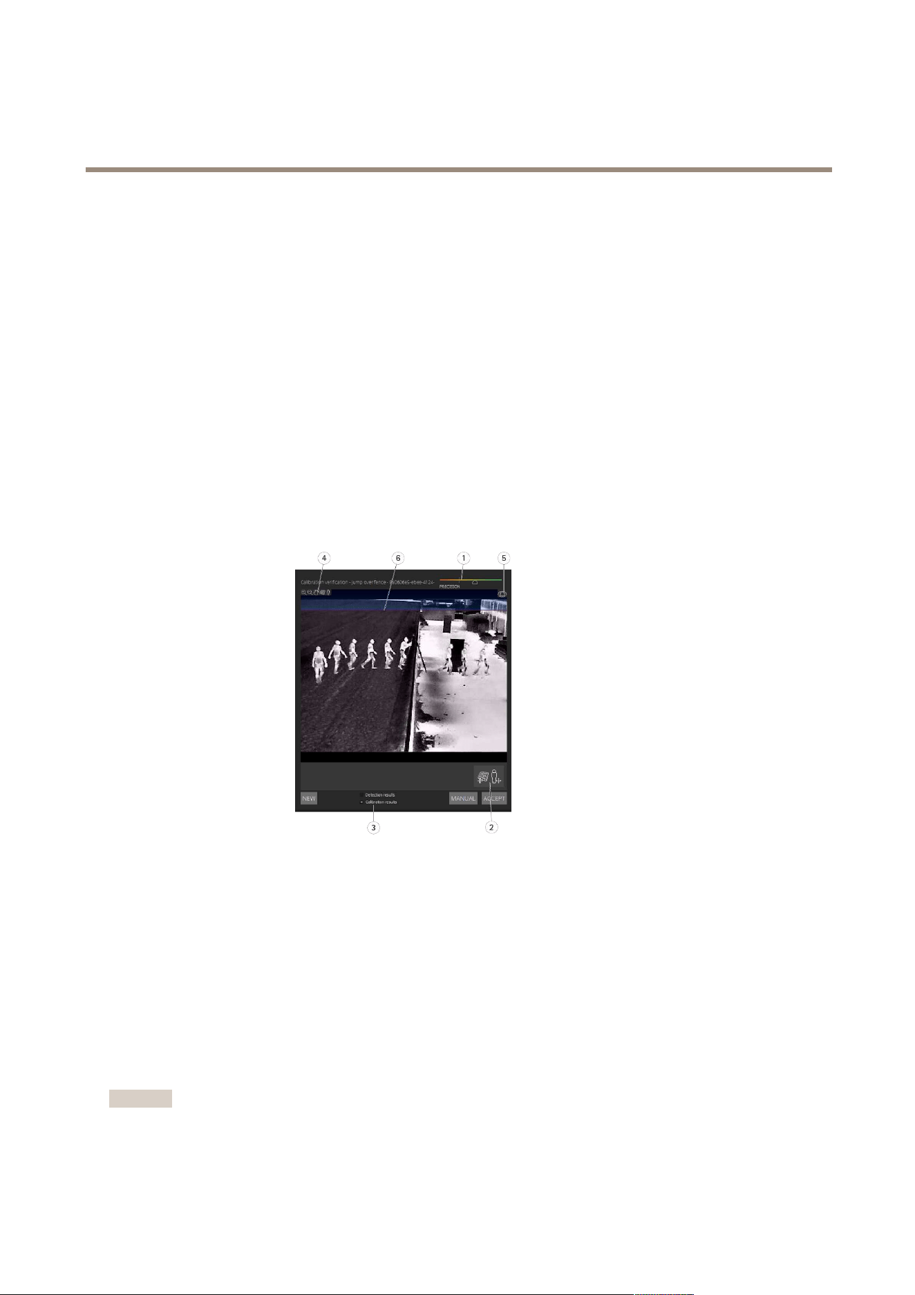
Verify the quality of the calibration
After a calibration, you should see the person who walked through the scene in several different places. If the person is not visible at
all, the automatic calibration has failed and needs to be redone.
There are several ways to verify the quality of the calibration:
• Check the calibration precision indicator. It reects an automatically computed precision level that measures how well the
person covered the scene and how well he or she was detected. If the precision indicator is in the red zone the calibration
has failed and you are not able to click Accept. See Perform a manual calibration on page 22.
• You can use the grid tool. See Use the grid to verify calibration on page 20.
• You can use the avatar tool. See Use the avatar to verify calibration on page 21.
• You can check the detection results. See Use detection results to verify calibration on page 22.
1
Calibration precision indicator
2
Grid and avatar tools
3
Dynamic or static view
4
View modiers
5
Toggle between calibration image and live view
6
Horizon line
The horizon line represents the visible end of the ground in the scene. When you dene scenarios, it is not possible to place scenario
zones in the blue area above the horizon line, as this is above the ground and scenario zones are by denition on the ground.
Use the grid to verify calibration
The grid should correspond to a square grid on the ground. You can toggle the display of the grid by clicking the grid view
modier icon.
Important
The grid does not affect the calibration, it is a tool to make sure the calibration is correct.
20
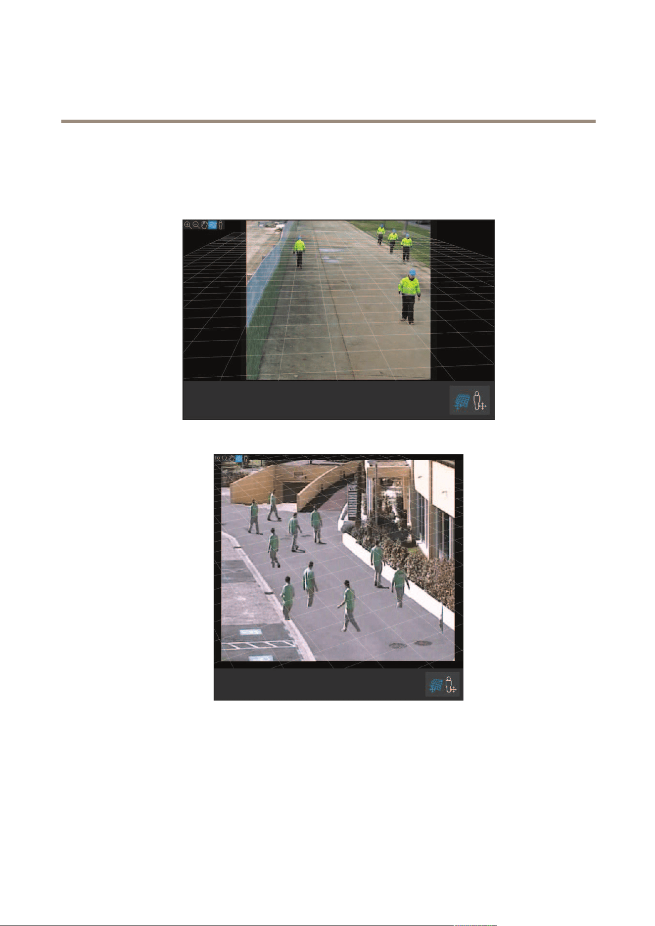
AXIS Perimeter Defender
Get started
You can turn the grid by dragging it in the preview pane. Try to align it with some structure in the scene to see if the result
seems reasonable.
If the grid is parallel to the ground, does not have a weird slope, and, after having applied the necessary rotation to the grid, is
parallel to man-made artefacts that are parallel in the real world, then the calibration is good.
An example where the grid is correctly aligned with the road shoulders.
An example where the grid is not correctly aligned with the road shoulders.
Use the avatar to verify calibration
The avatar allows you to place a 3D person avatar of average height in the scene. You can toggle the display of the avatar by
clicking the avatar view modier icon.
21
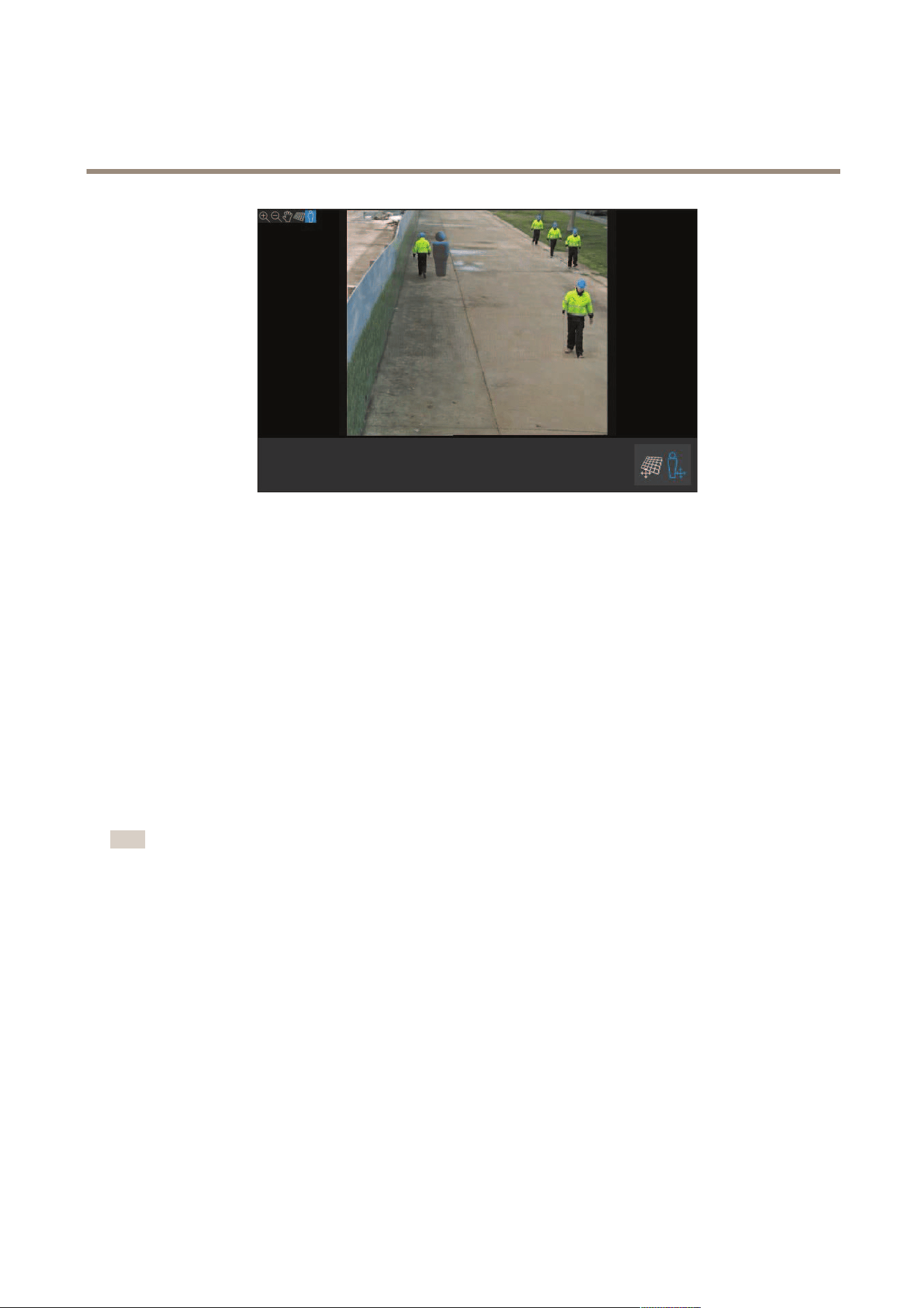
AXIS Perimeter Defender
Get started
Its size in the view pane corresponds to the size of an average person at that position according to the current calibration. By moving
the avatar around, you can make sure its size is reasonable in relation to other objects or people in the scene. You should check the
avatar at different positions, since the avatar could be correctly sized at one position but incorrectly sized elsewhere in the image.
Use detection results to verify calibration
You can use the detection results to check how AXIS Perimeter Defender would perform with the current calibration if it received the
video footage of the person’s walk as a live stream.
1. Switch from Calibration results to Detection results.
2. Check the detections of the people or vehicles entering the surveillance scene:
- If the calibration is ne, people are marked with red rectangles and vehicles with blue rectangles.
- If people or vehicles are frequently not marked, the automatic calibration has most likely failed.
- A red zone shows the detection limit zone according to the computed calibration, that is, the zone where
the prerequisites on the human height in the image are not respected. In this zone the detection might fail
because of the target size.
Note
• If the computed calibration is wrong, the red zone is also wrong.
• If the person is too far away, he or she might not be marked. A minimum size is necessary for the detection to work.
For more information, see Mount the camera on page 12.
• Reviewing detection results may not work on remotely connected cameras, because the capture can have a too low frame
rate. It does not mean that the conguration has failed. Use the avatar and the grid to verify calibration instead.
Perform a manual calibration
If you have not attempted an automatic calibration, you need to capture a short video and create a composite image before you can
perform a manual calibration. Follow the same steps as for an automatic calibration (Perform an automatic calibration on page 18),
but select Manual instead of Automatic in the Calibration tab. To create the composite image after you have captured a video:
• move the slider to navigate in the video clip
• at key positions, click the camera icon to add images to the composite
Make sure the composite image reects the full cross-section of the scene: front, back, left and right.
When you have a composite image, created manually or automatically, you can continue the manual calibration.
22

AXIS Perimeter Defender
Get started
The calibration engine calibrates by estimating:
• the horizon
• the way vertical lines spread, or fan out, in the image
• the scale of the scene
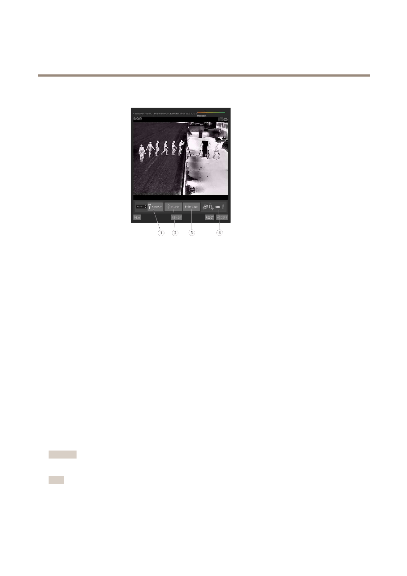
When you perform a manual calibration, you need to provide this information to the calibration engine through calibration elements.
There are three types of calibration elements:
• Person sticks are used to mark the known height of an average person at various positions in the scene. If you have already
attempted an automatic calibration, it is very likely that the image displayed in the editor pane shows several instances of
the same person. Place person sticks from the ground up to mark the height and direction of the person at one or more
positions. A person stick must start on the ground and should be vertical in the real world. The length of a person stick
in the real world must correspond to the height indicated next to the Person button in the editor pane. Person sticks
are marked with a semi-transparent light blue symbol.
How to best place a person stick
- We recommend that you place the stick on a person having their feet close together.
- If you place a stick on a person standing on the ground with the feet apart, place the lower point on the
ground halfway between the heels of the person.
- Align the stick should with the person's torso. However, if he or she is leaning in some direction, typically
forwards while walking, try to compensate the leaning by placing the stick more upright. Use any clues in the
scene to guide you, for example trees, fences, or lamp posts.
- For the scale of the scene, at least one person stick with the corresponding person height is needed. If there is
no person visible in the scene, you can add a person stick on some other vertical object of known height, for
example a 3 m fence post, and set the person height to the height of the object.
• Parallel horizontal lines (H-lines) are used to mark known horizontal and parallel lines in the scene. These lines can be on
the ground or on a wall or both, but they must all be parallel. If you add H-lines, you need to add at least two. You can
place them on the sides or the markings on a straight road, on a set of straight railroad tracks, on some visible structure on
a wall, or on the tops and bottoms of a row of fence posts. H-lines are marked in light blue.
• Vertical lines (V-lines) are used to mark known vertical lines in the scene. A V-line should mark some vertical structure in
the real world. This can be for example a fence post, the corner of a building, or a sign. A V-line does not need to start
on the ground. V-lines are marked in dark blue. Note that V-lines are very sensitive as a small change of orientation
may dramatically change the calibration. As a rule of thumb, V-lines should lean right on the right side of image and
left on the left side.
23
AXIS Perimeter Defender
Get started
1
Person sticks
2
Vertical lines (V-lines)
3
Parallel horizontal lines (H-lines)
4
Grid and avatar tools
Number of calibration elements
Generally, when you add person sticks, H-lines and V-lines in the scene, the more the better. The calibration engine can calibrate with
very few lines, but typically the calibration quality gets better the more lines and sticks you draw. When you add person sticks, we
recommend that you place them both near and far, left and right.
Vertical structures in the image
According to Recommendations when mounting the camera on page 13, all cameras must point slightly downwards. As a result, all
vertical structures in the real world seem to fan out like a peacock-tail in the image. This means that all person sticks and V-lines
should tilt towards the edge of the image. A stick on the right half of the image should lean to the right and a stick on the left should
lean to the left. At least one of the placed person sticks or V-lines must be “correctly leaning” for the calibration to work.
The precision indicator provides visual feedback on the level and quality of detail that has been added to the scene. For successful
manual calibrations, mark-ups should cover the scene from front to back and from left to right. This is indicated by a green
precision indicator.
Calibration quality
The quality of the calibration can be checked with the grid or avatar manipulators. See Verify the quality of the calibration on page
20. Alternatively, click Review. This shows you the result of running AXIS Perimeter Defender on the captured video using the
current manual calibration.
Calibrate - PTZ Autotracking
Important
To achieve good results, the calibration must be of high quality. Follow the guidelines and instructions carefully.
Note
You can calibrate both cameras at the same time, or one at a time.
1. Select both the xed camera and the PTZ camera.
24

AXIS Perimeter Defender
Get started
2. Go to Calibration and click Setup PTZ position. A pop-up with the view from the xed camera is shown.
The PTZ camera will pan, tilt, and zoom for a short while when the application starts up.
3. Check that the view from the two cameras are aligned with each other.
If they are not, click the live view image to adjust the view of the PTZ camera until it matches the view of the xed
camera. Make sure there is no roll.
4. Click Setup PTZ position.
If the button is not visible, move the pop-up with the view from the xed camera.
5. Click Automatic.
6. Perform an automatic calibration according to the instructions in Perform an automatic calibration on page 18.
7. Use the avatar to verify the quality of the calibration for the xed camera. See Use the avatar to verify calibration
on page 21.
If the quality is good enough, click Accept.
If the quality is not good enough, use the video from the automatic calibration to make a manual calibration. Click Manual
and follow the instructions in Perform a manual calibration on page 22.
8. In Scenarios, dene the rules for what should trigger alarms. See Dene scenarios on page 25.
9. In Calibration, click Review in the live view of the PTZ camera.
10. Use the avatar to verify the quality of the calibration for the PTZ camera. See Use the avatar to verify calibration on page 21.
If the quality is good enough, click Accept.
If the quality is not good enough, use the video from the automatic calibration to make a manual calibration. Click Manual
and follow the instructions in Perform a manual calibration on page 22.
11. Pair the cameras. See Pair the cameras - PTZ Autotracking on page 27.
Dene scenarios
Scenarios
AXIS Perimeter Defender includes common sterile zone scenarios that you can congure to secure and monitor sensitive areas. In
the calibration step, the maximum detection zone was created to provide a default scenario of the type intrusion/loitering. In this
step, you can dene more sophisticated detection scenarios of three different types:
• intrusion/loitering. See Set up the intrusion/loitering scenario on page 26
• zone-crossing. See Set up the zone-crossing scenario on page 26
• conditional. See Set up the conditional scenario on page 27
If the ! symbol appears by a scenario name, it means the scenario setup is not complete. The most common issue is that its
detection zone has not yet been dened.
Global parameters
The global parameters that you set in the user interface apply to all scenarios.
Camera type - For visual cameras, select Color - Day-Night. For thermal cameras, the camera type is automatically set to thermal.
Additional approach types - Select the ones you want to cover with your detection scenario. Note that additional approach types
can increase the risk of false alarms, for example caused by animals.
25

AXIS Perimeter Defender
Get started
Advanced mitigation - You can use Headlinghts/vehicles in scene if the scene contains vehicles, headlights, or headlight effects
such as reections. Note that if you use this setting, performance can sometimes be reduced in normal conditions. By default, all
scenarios are supposed to contain vehicles and thus headlights. You can use Insects/droplets on lens to ignore triggers from
rain drops or insects, and reduce false alarms.
Sensitivity - To increase the sensitivity of the system, move the slider to the right. A higher sensitivity reduces the risk of missed
detections, but increases the risk of false alarms.
Duration parameters
For each scenario you create, you can set duration parameters.
Min presence in zone - Set the time that an object has to stay in a zone for the zone to be activated.
Narrow zone - If the zone is narrow and can be crossed in 1–2 seconds, there is a risk of missed alarms. You can mitigate this with
the Narrow zone functionality. Note that it can’t be combined with Min presence in zone.
Set up the intrusion/loitering scenario
The intrusion/loitering scenario is designed to trigger an alarm when an object enters a certain zone and remains in the zone
for longer than the predened time.
The default scenario created in the calibration step is of the type intrusion/loitering, and it uses the maximum detection zone. To
use this scenario as it is, click Accept in the Scenarios tab.
To change the default scenario:
1. Go to Scenarios > Advanced scenarios.
2. Change the default detection zone:
- To move existing points in the detection zone, click and drag them with the mouse.
- To create additional points, click any of the existing segments and drag with the mouse.
3. Under Detect, select what type of objects to detect.
4. Under Duration parameters, if you don’t want an object to trigger an alarm as soon as it enters the zone, set the loitering
time in Min presence in zone.
5. If the zone is narrow and can be crossed in 1–2 seconds, and you still want alarms to trigger, select Narrow zone. This
setting can’t be combined with Min presence in zone. For more information, see Duration parameters on page 26.
6. To upload the changes to the camera and switch back to the main view, click Accept.
Set up the zone-crossing scenario
The zone-crossing scenario is designed to trigger an alarm when an object passes through two detection zones in a given sequence.
Important
The zone-crossing scenario has the following limitation: if the object that triggers the scenario stops moving for a few
seconds in the origin zone before moving on to the end zone, the scenario doesn’t trigger.
Under Duration parameters, you can dene a minimum presence time for each of the zones in the scenario. If T
A
is the minimum
time in the origin zone and T
B
in the end zone, an alarm only triggers if the object stays longer than T
A
in the origin zone and
then longer than T
B
in the end zone.
1. Go to Scenarios > Advanced scenarios.
2. Click New and select Zone-crossing.
3. Create two detection zones separated by at least one meter (3 feet 3 3/8 inches):
26

AXIS Perimeter Defender
Get started
- To create a detection zone, click multiple times in the image.
- To nish the zone, right-click in the image.
4. To specify the forbidden crossing direction, click Select origin and then click one of the zones.
5. Under Detect, select what type of objects to detect.
6. Under Duration parameters, if you don’t want a zone to be activated as soon as an object enters, set the Min presence
in for one or both zones.
7. If the zone is narrow and can be crossed in 1–2 seconds, and you still want alarms to trigger, select Narrow zone. This
setting can’t be combined with Min presence in zone. For more information, see Duration parameters on page 26.
8. To upload the changes to the camera and switch back to the main view, click Accept.
Set up the conditional scenario
The conditional scenario is designed to trigger an alarm when an object enters a certain zone without rst passing through others.
Under Duration parameters, you can dene a minimum presence time for each of the zones in the scenario. If T
A
is the minimum
time in the authorized zone and T
B
in the intrusion zone, an alarm only triggers if the object:
• stays longer than T
B
in the intrusion zone without having entered the authorized zone rst.
• stays shorter than T
A
in the authorized zone, then enters and stays longer than T
B
in the intrusion zone.
No alarm triggers if the object:
• doesn’t enter or stays shorter than T
B
in the intrusion zone.
• stays longer than T
A
in the authorized zone, then enters the intrusion zone (regardless of how long the object stays).
1. Go to Scenarios > Advanced scenarios.
2. Click New and select Conditional.
3. Create two or more detection zones separated by at least one meter (3 feet 3 3/8 inches):
- To create a detection zone, click multiple times in the image.
- To nish the zone, right-click in the image.
4. To specify the allowed crossing direction, click Select intrusion zone and then click one of the zones.
5. Under Detect, select what type of objects to detect.
6. Under Duration parameters, if you don’t want a zone to be activated as soon as an object enters, set the Min presence
in for one or both zones.
7. If the zone is narrow and can be crossed in 1–2 seconds, and you still want alarms to trigger, select Narrow zone. This
setting can’t be combined with Min presence in zone. For more information, see Duration parameters on page 26.
8. To upload the changes to the camera and switch back to the main view, click Accept.
Pair the cameras - PTZ Autotracking
In the setup for AXIS Perimeter Defender PTZ Autotracking, you must pair the xed camera and the PTZ camera with each other to
make sure a moving object is tracked in an efcient way by the PTZ camera.
If you performed an automatic calibration, you can Perform an automatic pairing on page 28 of the two cameras. Otherwise you
need to Perform a manual pairing on page 28.
27

AXIS Perimeter Defender
Get started
Perform an automatic pairing
In the pairing video, the red lines represent the person, and the orange bounding box represents the zoomed-in image of the PTZ
camera.
1. In Calibration > PTZ Pairing review, verify the pairing videos from the two cameras:
- check that the red lines in the two images are aligned throughout the video
- check that the red lines always go from feet to head of the person
- check that the person is always centered within the orange bounding box in the PTZ camera video
2. If the conditions in step 1 are fullled, select Interactive pairing review.
If the conditions are not fullled, click Manual and follow the steps in Perform a manual pairing on page 28.
3. Move the slider to navigate in the video clip. Check that:
- the blue lines in the two images are aligned throughout the video
- the person is always centered within the orange bounding box in the PTZ camera video
4. If there are scenes where the orange bounding box is missing:
4.1 Activate the avatar in the xed camera image.
4.2 Use the slider to move back and forth in the video. Place the avatar at the person in the xed camera view, and
check that the red dot is at the feet of the person in the image from the PTZ camera.
5. If there are scenes where the automatic pairing did not add blue lines, click Manual and add red lines manually at the
person. See Perform a manual pairing on page 28 for detailed instructions.
6. Click Accept and Exit.
Perform a manual pairing
When you perform a manual pairing, you add vertical red lines from feet to head of the person who walked through the surveillance
scene in the calibration step. You need to add lines throughout the video, to cover the whole scene.
If you already performed an automatic pairing, the video already contains blue lines.
Remove blue and red lines that:
• don’t start at the person’s feet
• don’t go all the way to the person’s head
• don’t have a corresponding line in the PTZ camera image
To remove a line, click it and press DELETE.
1. Move the slider to navigate to an image in the video clip where the person is visible.
2. Add a red line at the person in the xed camera image. Start the line at the person’s feet. The line gets an ID number.
3. Add a corresponding red line at the same object in the PTZ camera image. Check that the ID number matches the one in
the xed camera image.
4. Repeat steps 1–3 until you have covered the whole scene.
When the video clip contains a sufcient number of lines for a valid pairing:
- the Accept button becomes active
- an orange bounding box is shown in the PTZ camera image
28

AXIS Perimeter Defender
Get started
5. Check that the person is always centered within the orange bounding box. If there are scenes where it’s not, add more
red lines.
6. Activate the avatar in the xed camera image.
7. Move the slider to navigate in the video clip. Use the avatar to check that:
- in the xed camera image, the size of the avatar corresponds to the person’s size, in different positions
- in the PTZ camera image, the red dot is at the feet of the person
- in the PTZ camera image, the person is always centered within the orange bounding box
8. Click Accept. If the button is inactive, you need to add more red lines rst.
9. Click Exit.
Dene outputs
Outputs
To make AXIS Perimeter Defender output alarms when it detects an intrusion, you need to dene rules for it. The system can
send alarms to, for example, a VMS.
AXIS Perimeter Defender can send alarms through different interfaces.
From the application itself:
• XML or plain text alarm notications over TCP/IP
• XML metadata streams over multipart HTTP
From the device:
• Basic free text notications for alarms over TCP/IP
• Electrical outputs (dry or wet contacts)
• E-mail notications
• FTP upload of alarm images
You can activate several interfaces at the same time.
For more in-depth information, see Outputs on page 31.
Dene outputs
To dene rules for sending alarms from the device:
1. Go to Outputs and click Congure. The device's webpage opens in a web browser.
2. Create a new action rule.
3. From the list of triggers, select Applications, then AXISPerimeterDefender and the scenario to trigger the action.
Note
To trigger the same action for all dened scenarios, select ALL_SCENARIOS.
4. From the list of actions, select the action to perform when the condition is met.
5. Click OK.
29

AXIS Perimeter Defender
Get started
For more detailed information about how to create action rules, see the device's user manual.
30

AXIS Perimeter Defender
Advanced configuration
Advanced configuration
Outputs
XML/text alarm notications
This interface allows a TCP/IP recipient to receive a more complete and descriptive XML or text message for each alarm. With respect
to the free-text interface, the XML/text interface offers the following advantages:
• A notication is sent at the beginning of the alarm, at the end of the alarm and every 10 seconds during the alarm.
• Timestamp: the start-of-alarm and end-of-alarm notications contain a timestamp which is synchronized with the camera
clock and gives the exact date and time of the events.
• Alarm type: AXIS Perimeter Defender supports several alarm types, see Dene scenarios on page 25. The XML/text
notications contain the information of which type of alarm has been triggered. Pay attention: the “zone crossing”
scenario has type “passage” and the loitering scenario has type “presence”
• Zone(s) involved in the alarm generation; where each AXIS Perimeter Defender scenario is associated to one or more
zones, the XML/text notications include which zone is associated to the alarm (i.e., for an intrusion alarm, the intrusion
zone in which a person has been detected)
With respect to the free-text interface, the XML/text interface has the following limitations:
• The message text is xed, and there are no free-text elds.
• Only one recipient is supported per camera at a time.
The recipient of the XML/text notications receives four types of messages:
• AXIS Perimeter Defender sends a CONNECTION_TEST message when the XML notication is congured in order to verify
that the communication with the recipient works as expected.
• When AXIS Perimeter Defender triggers an alarm, it sends an ALARM_START message.
• During the alarm duration, AXIS Perimeter Defender sends several “alarm in progress” messages, one every 10 seconds. All
these messages have the same GUID tag, identical to that of the ALARM_START message and ALARM_STOP messages
related to the same alarm
• At the end of the alarm, AXIS Perimeter Defender sends an ALARM_STOP alarm.
For explanation of the format of these messages, both in XML and text format, see XML and text format examples on page 31.
XML and text format examples
The XML format is the default format for the TCP/IP notications. Nevertheless, if the notication size is important, a text format,
generating shorter messages, can be used. In order to select the text format, the Do not use XML for alarms parameter must be
selected in the AXIS Perimeter Defender conguration page.
Example
A CONNECTION_TEST message in XML format looks like this example:
<?xml version="1.0"?>
<KEENEO_MESSAGE xmlns:xsi="http://www.w3.org/2001/XMLSchema-instance"
xmlns:xsd="http://www.w3.org/2001/XMLSchema"
VERSION="5.0.0"
ID="1"
TYPE="CONNECTION_TEST"
SENDER_IP="192.168.1.40"
SENDER_PORT="0">
<REFERENTIAL>45</REFERENTIAL>
31

AXIS Perimeter Defender
Advanced configuration
</KEENEO_MESSAGE>
• VERSION is the internal version of the XML syntax and protocol.
• ID is a numeric identity for the message. ID’s are not guaranteed to be unique nor progressive.
• TYPE is the type of the message, here “CONNECTION_TEST”. The message type determines the sub-tags of the message
(none for messages of type “CONNECTION_TEST”).
• SENDER_IP is the ip address of the Axis camera sending the XML notication.
• SENDER_PORT is always zero; the camera cannot receive incoming messages.
• REFERENTIAL is the numeric ID associated to the camera
If the text format is chosen, the notication messages contain 7 elds each, separated by the “pipe” character “|”. If a eld can’t be
specied (for example, it does not make sense for that message type), it is replaced by “-“.
The seven elds are, from the rst to the last (in parenthesis, the corresponding XML eld when the format is XML):
1. The message numeric ID (“ID” attribute of the XML “KEENEO_MESSAGE” header).
2. The IPv4 address of the camera (“SENDER_IP” attribute of the XML “KEENEO_MESSAGE” header).
3. The referential number associated to the AXIS Perimeter Defender instance (“REFERENTIAL” tag).
4. The message type (“TYPE” attribute of the XML “KEENEO_MESSAGE” header).
5. The alarm type (“TYPE” tag).
6. The name of the scenario that has triggered the alarm (“SCENARIO_NAME” tag).
7. The timestamp (“TIMESTAMP” tag). The timestamp format is the same as for the XML format.
The previous CONNECTION_TEST message in TEXT format is:
1|192.168.1.40|45|CONNECTION_TEST|-|-|-
Example
An ALARM_START message in XML format looks like this example:
<?xml version="1.0"?>
<KEENEO_MESSAGE xmlns:xsi="http://www.w3.org/2001/XMLSchema-instance"
xmlns:xsd="http://www.w3.org/2001/XMLSchema"
VERSION="5.0.0"
ID="9999"
TYPE="ALARM_START"
SENDER_IP="192.168.1.40"
SENDER_PORT="0">
<REFERENTIAL>0</REFERENTIAL>
<TYPE>INTRUSION</TYPE>
<SCENARIO_NAME>Intrusion-0</SCENARIO_NAME>
<EXTRA_DATA>zone=testzone</EXTRA_DATA>
<TIMESTAMP>2014-03-01T21:24:12.114</TIMESTAMP>
<GUID>77acddf9-e0d4-402e-a497-231aeee22788</GUID>
</KEENEO_MESSAGE>
• The message header is the same as the “CONNECTION_TEST” message.
• The message type is “ALARM_START”, and has a set of sub-tags.
- REFERENTIAL is the numeric ID associated to the camera.
- TYPE is the type of the alarm triggered by AXIS Perimeter Defender, “INTRUSION” in this example. Other possible
types are “PRESENCE”, “PASSAGE” and “CONDITIONAL”.
32

AXIS Perimeter Defender
Advanced configuration
- SCENARIO_NAME is the name of the scenario that triggered the alarm, as dened in the conguration interface.
See Set up the intrusion/loitering scenario on page 26
- EXTRA_DATA carries the zone name (or list of zone names) involved with the alarm, like the intrusion zone.
- TIMESTAMP is the date and time of the alarm start, in the format YYYY-MM-DDTHH:mm:ss.zzz, where:
– YYYY is the year on 4 digits, like 2014.
– MM is the month number on 2 digits, like 01 for January.
– DD is the day number on 2 digits, like 03 for the 3rd.
– ‘T’ is a xed letter
– HH is the hour in 24-hour format, from 00 to 23
– mm are the minutes on 2 digits, from 00 to 59
– ss are the seconds on 2 digits, from 00 to 59
– zzz are the milliseconds on 3 digits, from 000 to 999.
AXIS Perimeter Defender uses the camera internal date and time for generating the alarm timestamp, thus it is
important to synchronize the camera with some kind of external clock.
- GUID is a unique identier that is constant for all messages related to the same alarm (so ALARM_START,
ALARM_IN_PROGRESS and ALARM_STOP)
This is the equivalent, in text format, of the ALARM_START message:
9999|192.168.1.40|0|ALARM_START|INTRUSION|Intrusion-0|2014-03-01T21:24:12.114
Example
An ALARM_IN_PROGRESS message in XML format looks like this example:
<?xml version="1.0"?>
<KEENEO_MESSAGE xmlns:xsi="http://www.w3.org/2001/XMLSchema-instance"
xmlns:xsd="http://www.w3.org/2001/XMLSchema"
VERSION="5.0.0"
ID="9999"
TYPE="ALARM_IN_PROGRESS"
SENDER_IP="192.168.1.40"
SENDER_PORT="0">
<REFERENTIAL>0</REFERENTIAL>
<TYPE>INTRUSION</TYPE>
<SCENARIO_NAME>Intrusion-0</SCENARIO_NAME>
<GUID>77acddf9-e0d4-402e-a497-231aeee22788</GUID>
</KEENEO_MESSAGE>
• The message header is the same as the “CONNECTION_TEST” and “ALARM_START” message.
• The message type is “ALARM_IN_PROGRESS”, and has a set of sub-tags.
- REFERENTIAL is the numeric ID associated to the camera.
- TYPE is the type of the alarm triggered by AXIS Perimeter Defender the same of the corresponding ALARM_START.
- SCENARIO_NAME is the name of the scenario that triggered the alarm, the same of the corresponding
ALARM_START.
- The GUID is the same of the corresponding ALARM_START.
The corresponding ALARM_IN_PROGRESS message in TEXT format:
33

AXIS Perimeter Defender
Advanced configuration
9999|192.168.1.40|0|ALARM_IN_PROGRESS|INTRUSION|Intrusion-0|-
Example
An ALARM_STOP message in XML format looks like this example:
<?xml version="1.0"?>
<KEENEO_MESSAGE xmlns:xsi="http://www.w3.org/2001/XMLSchema-instance"
xmlns:xsd="http://www.w3.org/2001/XMLSchema"
VERSION="5.0.0"
ID="9999"
TYPE="ALARM_STOP"
SENDER_IP="192.168.1.40"
SENDER_PORT="0">
<REFERENTIAL>0</REFERENTIAL>
<TYPE>INTRUSION</TYPE>
<SCENARIO_NAME>Intrusion-0</SCENARIO_NAME>
<EXTRA_DATA>zone=testzone</EXTRA_DATA>
<TIMESTAMP>2014-03-01T21:24:26.304</TIMESTAMP>
<GUID>77acddf9-e0d4-402e-a497-231aeee22788</GUID>
</KEENEO_MESSAGE>
• The message header is the same as the previous messages.
• The message type is “ALARM_STOP”, and has the same set of subtypes of the ALARM_START message.
The corresponding ALARM_IN_PROGRESS message in TEXT format:
9999|192.168.1.40|0|ALARM_STOP|INTRUSION|Intrusion-0|2014-03-01T21:24:26.304
The TCP/IP connection is always closed after each message. Therefore, the recipient has to keep the listening socket always open
for being able to receive further notications.
Communication errors
If the remote recipient of XML notications is not reachable, for example because of a network disconnection, AXIS Perimeter Defender
starts buffering the non-delivered alarms internally and periodically (at least every 10 seconds) tries to deliver them again. After a
consecutive number of failures in delivering new messages (failures while trying to deliver again a message from the buffer does not
account for that), AXIS Perimeter Defender declares the recipient as “permanently ofine” and stops sending XML notications to
the recipient. The number of consecutive failures is xed to 20, roughly corresponding to 4 or 5 intrusion alarms of an average
duration of 40 seconds each. AXIS Perimeter Defender starts sending notications to the same recipient again if one of the following
events occurs:
• AXIS Perimeter Defender is restarted.
• The same value of the parameter “Alarm streaming url” is saved again.
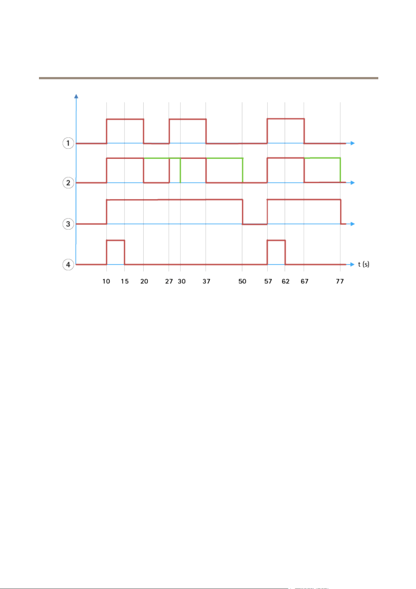
Post-alarm time
AXIS Perimeter Defender implements the notion of “post-alarm time”. This is dened as the time interval after an alarm stops, during
which, if another alarm is triggered, both alarms are merged into a unique one.
34
AXIS Perimeter Defender
Advanced configuration
1
Three alarms triggered by AXIS Perimeter Defender at time 10, 27 and 57. Each alarm has a duration of 10 seconds,
i.e. an intruder has taken 10 seconds to cross the intrusion zone.
2
A post-alarm time of 10 seconds is added.
3
Alarms using XML notications and XML metadata.
4
Alarms using email notications, ftp image upload, electrical contacts and basic TCP/IP notications.
(2) Notice how a post-alarm time of 10 seconds (in green) increases the duration of each alarm, thus leading to the fusion (merge) of
two alarms that are separated by 10 seconds or less.
(3) You can see the resulting alarm number and duration as raised by AXIS Perimeter Defender through XML notications and XML
metadata. The post-alarm time can be used for obtaining fewer longer alarms instead of several, shorter and consecutive ones.
(4) For email notications, ftp image upload, electrical contacts, and basic TCP/IP notications, the result of using a 10 second
post-alarm time is different. These notications only consider the alarm start, and neglect the alarm stop. Thus, there is no notion of
“alarm duration” when you use these notications, and, as a consequence, the post-alarm time does not change the duration of the
notication itself. It is always xed to the value chosen by the user when conguring the notication. So, when consecutive alarms
are merged into one because of the post-alarm time, only one notication is sent. You can see that AXIS Perimeter Defender merges
the rst two alarms, thus sending only one notication. Therefore, email notications, ftp image upload, electrical contacts and basic
TCP/IP notications noties only for two of them. The graph shows a xed duration of 5 seconds for these notications.
How to congure the post-alarm time
1. Open AXIS Perimeter Defender Setup.
2. Go to Outputs.
3. Change the Post-alarm time setting. The default value is 7 seconds.
4. Click Assign.
35

AXIS Perimeter Defender
Advanced configuration
Metadata
Burnt-in metadata overlay
Burnt-in metadata overlay is a feature that can draw analytics detections to selected live streams directly in the camera. The
detections are graphical overlays in the form of bounding boxes and trajectory lines. The streams are selected based on their
resolution and, if the device has support for view areas, on a view area. The burnt-in metadata shows up both in live view and
during playback of recorded material.
Burnt-in metadata overlays on selected streams
For example, you can set up the application to add overlays on all streams with resolution 640x480. In that case, only the streams
with this resolution have the overlay, and the others stay unmodied.
Burnt-in metadata overlays on selected view areas
When supported, you can also indicate a view area along with the resolution. For example, you can choose to have overlays on
streams fetched from view area number 3 at resolution 1280x720. In this case, only the streams matching this conguration will
have the overlays, and other streams will stay unmodied including those fetched from view area 3 but at a different resolution, and
those fetched at 1280x720 but not from view area 3.
Add burnt-in metadata to the video stream
Note
This function is only available on devices with rmware 7.30 or later.
This example explains how to turn on burnt-in metadata overlays on all video streams with resolution 640x480. Video streams with
any other resolution stay unaffected.
1. Select camera in the panel with live views.
2. Go to Outputs > Burnt-in Metadata Overlay.
3. Select Enabled.
4. In the drop-down list, select resolution 640x480.
5. Click Apply.
6. Make sure the metadata shows up in the live view for that resolution.
VMS integration
AXIS Perimeter Defender integrates seamlessly with the following video management systems (VMS):
• Security Center from Genetec™
• XProtect® from Milestone
For information about the VMS versions supported, see axis.com/products/axis-perimeter-defender/support-and-documentation
Alarms triggered by AXIS Perimeter Defender are automatically converted to events in the VMS, which in turn can trigger a wide
set of actions and leverage the full power of the VMS. Simultaneously, the live metadata generated by AXIS Perimeter Defender
is sent to the VMS for live display and recording. Therefore, the metadata is also available when playing the recorded video
sequences in playback mode.
An automated intrusion detection system is designed to trigger alarms and provide information that helps inform the security
intervention. This may include providing a prompt to a mobile device or displaying the alarm event within a VMS perhaps with the
subject that created the alarm event highlighted on screen.
36

AXIS Perimeter Defender
Advanced configuration
Standard event integration
AXIS Perimeter Defender leverages and extends the native ACAP interfaces and capabilities for sending alarms and supplementary
information to external devices or VMS. Events output by AXIS Perimeter Defender can be translated into messages to the VMS,
by connecting action rules to them.
The following alarm channels from the camera to the VMS are available:
• Basic free text notications for alarms (TCP/IP)
• Electrical outputs (dry or wet contacts)
• Email notications
• Ftp upload of alarm images
These integrations can be congured on the camera. See Post-alarm time on page 34.
VMS Bridges
For the following video management systems, we provide pre-developed integration modules, referred to as “bridges”:
• Milestone XProtect® 2014 and 2016 Corporate/Expert/Enterprise/Professional/Express. Enterprise/Professional/Express
editions do not support metadata (no live or playback display of metadata)
• Genetec
TM
Service Center 5.3 and 5.4 Pro/Enterprise/SV32/SV16
The bridges provide two integrations:
• Creating custom alarm events in the VMS, matching the events output by AXIS Perimeter Defender.
• Displaying alarm overlays, or bounding boxes, on top of live and recorded video material from (except for Milestone
XProtect® Enterprise/Professional/Express editions).
You need to download and install the VMS bridges as separate applications. For more information on how to install and congure
these bridges, see the user manual for the specic bridge.
37

AXIS Perimeter Defender
Troubleshooting
Troubleshooting
For all functionalities to work as expected, it is mandatory to congure the following Axis parameters:
• Network / TCP-IP / Basic / Default router
• Network / TCP-IP / Advanced / Domain name
• Network / TCP-IP / Primary DNS Server
• Network / TCP-IP / Secondary DNS Server
• Network / TCP-IP / NTP server address
• Network / TCP-IP / SMTP (email)
• System Options / Date & Time / Time Zone
• System Options / Date & Time / Synchronize with NTP server
Update to the latest version
To take advantage of latest improvements without having to re-calibrate and redene scenarios, we recommend that you upgrade to
the latest version of AXIS Perimeter Defender.
1. Download and install the latest version of AXIS Perimeter Defender.
2. Click Install. AXIS Perimeter Defender Setup automatically performs the necessary steps for completing the installation:
- Back-up the existing calibration, scenarios, parameters and license.
- Install new version.
- Restore license.
- Restore calibration and scenarios.
- Restore parameters.
- If an application was running it is restarted.
Upgrade camera rmware
Note
Before upgrading the camera rmware, save all AXIS Perimeter Defender settings. Upgrading the rmware removes the
application and its settings from the camera. If settings are saved, they can be restored using AXIS Perimeter Defender Setup.
1. Use AXIS Perimeter Defender Setup to save the site conguration.
2. Upgrade the camera rmware. For instructions, see the camera's User Manual.
3. Start AXIS Perimeter Defender Setup.
4. Use the load site option to automatically load the saved site conguration for each upgraded camera.
38
AXIS Perimeter Defender
Troubleshooting
Installation troubleshooting
Problem Possible reason
Solution
There is a Windows
®
message saying it is
impossible to install the software.
The operating system on the laptop or PC
is not compatible.
Verify the Windows
®
operating
system matches that specied in the
requirements.
There is a Windows
®
message saying the
installation was incorrect.
Windows
®
Compatibility Assistant has
detected a possible problem with the
installation.
Conrm that the installation is correct
anyway and proceed.
Installation fails during installation of
XVID.
Installation of XVID fails because of old
partial installation of XVID present on
computer.
Delete the XVID folder in C:\Program Files
(x86) and try installing again.
The installer package suddenly crashes
after the EULA display. There is a
Windows
®
error message telling that the
application exited in an unusual way. It is
impossible to close the installer.
A known problem in the installers leads
to an application crash under some
circumstances.
Open task manager and kill all
“msiexec.exe” processes. Then kill the
installer process and restart the installer.
Conguration troubleshooting
Problem Possible reason
Solution
Problems with opening AXIS Perimeter De-
fender.
You do not have sufcient Windows
®
user
rights.
Make sure you have administrator rights.
Firewall Firewalls and antivirus software can
sometimes block camera discovery.
If required, congure the rewall to
allow network trafc to and from
AXIS Perimeter Defender. If this does not
solve the problem, congure the rewall
to allow the following ports: UDP port
5353 and TCP port 80.
IP address problems Any device in a network must have
a unique IP address to be able to
communicate with other devices. When
using AXIS Perimeter Defender, it is
recommended to use xed IP addresses
for the cameras. Make sure that every
IP device on the network has its own IP
address and does not reuse an already
taken IP address.
The search functionality does not nd my
cameras.
The camera is not available from the user
computer.
In a browser, go to the IP address of the
camera to conrm whether it is available
or not. If you cannot reach it, then the
camera has not been correctly installed
on the network or the computer does not
have access to the camera.
39
AXIS Perimeter Defender
Troubleshooting
Problem Possible reason
Solution
Camera connection parameters, for
example IP address, password or HTTP
port, are incorrect.
Verify the parameters entered are correct
and repeat.
It is not possible to add a camera.
The camera cannot be seen from the
user’s computer.
In a browser, go to the IP address of the
camera to conrm whether it is available
or not. If you cannot reach it, then the
camera has not been correctly installed
on the network or the computer does not
have access to the network which the
camera is on.
Video Source is no longer available.
The video source has been interrupted
and has not refreshed on the display.
Loss of video streams in the
AXIS Perimeter Defender Setup.
Use a browser to check if the camera is
available.
Click the tile where the stream should be
and resize the interface and the stream
should come back.
Prerequisites are not met. Make sure the mounting requirements are
met. See Mount the camera on page 12.
The camera has a roll. It is not possible to calibrate camera
having a roll.
Slow connection to camera not congured
as remote.
Connect camera as remote device to
lower bandwidth requirements.
There are other moving objects in the
scene used for the automatic calibration
such as cars, trees or other persons.
Repeat the auto-calibration, or calibrate
the device manually.
The eld of view is cluttered making the
person walking in front of the camera
partially hidden a lot of the time.
Calibrate the device manually.
The eld of view is small like indoor
corridors, rooms or outdoor entrances.
Calibrate the device manually.
The automatic calibration does not work
or yields bad results.
The capture video was not properly
recorded because of insufcient disk
space.
Check that there is adequate disk space
and that the application has permission to
save the video recording on the computer
where the AXIS Perimeter Defender
interface is running.
Operation troubleshooting
Problem Possible reason
Solution
The application does not run even though
the conguration is good.
The rmware of the camera is not
up-to-date.
Make sure you have the latest rmware
for the camera.
The application is blocked after a start
or stop operation or an upgrade of the
AXIS Perimeter Defender package.
Restart the camera.
A rewall is blocking the connection to
the camera metadata listening port.
Congure the rewall in order to allow
the conguration interface to connect
to the metadata listening port on the
camera.
The overlay is not displayed in
AXIS Perimeter Defender Setup even
though the analysis is running.
An antivirus program is blocking the
reception of the overlay.
Congure the anti-virus in order to allow
the overlay to be received.
40
AXIS Perimeter Defender
Troubleshooting
Although the target is in the scene it’s
not matching a conditional scenario, for
example not moving from one zone to
another in the zone crossing scenario.
Make sure the scenario is correctly
specied, including conditions.
No alarms are triggered in the
AXIS Perimeter Defender setup on the
conguration computer even though the
analysis is running and the overlay is
visible.
Poor detection. Make sure the mounting requirements
are met. See Mount the camera on page
12. Also make sure that the calibration is
precise enough and that the sensitivity
is high enough.
Performance troubleshooting
Problem Possible reason
Solution
OSD and analysis keeps switching on and
off.
CPU charge on the camera is too high.
Possible solutions:
• Make sure the stream of the
camera is not visualized in
unnecessary places because
every visualization of the
camera stream increase CPU
load.
• If recording on in-built
motion detection is activated
try to decrease the quality of
the recording to free up CPU.
• Deactivate recording on
in-built motion detection and
make sure in-built motion
detection is deactivated.
A target enters the sterile zone and
causes multiple alerts to be raised.
The duration of the post-alarm time is
too short.
Adjust the post-alarm time. Go to
AXIS Perimeter Defender Setup >
Outputs.
Contrast of the object against the
background in the scene is too low.
Make sure the mounting requirements are
met. See Mount the camera on page 12.
There is inadequate lighting in the scene
or the low light performance of the
camera is insufcient.
Make sure the mounting requirements are
met. See Mount the camera on page 12.
AXIS Perimeter Defender has the
sensitivity set too low.
Increase the sensitivity in the global
scenario parameters.
Camera has moved rendering the
calibration incorrect.
Redo the calibration.
The calibration is not precise enough.
Verify the calibration of the camera. Go
to AXIS Perimeter Defender Setup.
A potential target enters the sterile zone
but does not raise an alert – missed
detection.
Although the target is in the scene it is
not matching a conditional scenario e.g.
not moving from one zone to another in
the zone crossing scenario.
Make sure the scenario is correctly
specied, including conditions.
41
AXIS Perimeter Defender
Troubleshooting
Problem Possible reason
Solution
The camera height, positioning or
orientation is incorrect.
Make sure the mounting requirements are
met. See Mount the camera on page 12.
The camera is too far away from the zone. Make sure the mounting requirements are
met. See Mount the camera on page 12.
The target is detected but is incorrectly
classied (person as vehicle or vehicle as
person).
Calibration is not precise enough. Verify the calibration of the camera. Go
to AXIS Perimeter Defender Setup.
Sensitivity of analysis is too high. Decrease the sensitivity. Go to
AXIS Perimeter Defender Setup.
Calibration is not precise enough. Verify the calibration of the camera. Go
to AXIS Perimeter Defender Setup.
Camera has moved rendering the
calibration incorrect.
Redo the calibration.
Wrong camera height, positioning or
orientation.
Make sure the mounting requirements are
met. See Mount the camera on page 12.
Camera is moving, for example swaying
or vibrating.
Install the camera in a more stable
environment.
Vegetation or other moving objects, for
example ags, close to the camera.
Remove the offending items from the
camera eld of view. Objects that
are constantly in the scene but not
close to the camera are ignored by
AXIS Perimeter Defender.
AXIS Perimeter Defender generates an
alarm when there is not an intrusion into
the sterile zone.
Insects are crawling on or near the
camera lens.
Deter insects where possible from
encroaching on or near the camera lens.
42

This manual is intended for administrators and users of
AXIS Perimeter Defender. It includes instructions for using and
managing the product on your network. Previous experience of
networking of use when using this product.
Trademark acknowledgements
AXIS COMMUNICATIONS, AXIS and VAPIX are registered trademarks or
trademark applications of Axis AB in various jurisdictions. All other
company names and products are trademarks or registered trademarks
of their respective companies.
Apple, Apache, Bonjour, Ethernet, Internet Explorer, Linux, Microsoft,
Mozilla, Real, SMPTE, QuickTime, UNIX, Windows, and WWW are
registered trademarks of the respective holders. Java and all Java-based
trademarks and logos are trademarks or registered trademarks of
Oracle and/or its afliates. The UPnP Word Mark and UPnP Logo are
trademarks of Open Connectivity Foundation, Inc. in the United States
or other countries.
Genetec is a trademark and Milestone XProtect® is a registered
trademark of respective holders.

User Manual Ver. M14.3
AXIS Perimeter Defender
Date: March 2020
© Axis Communications AB, 2016 - 2020
Part No. T10068952