
Loading ...
Loading ...
Loading ...
45
AXIS P1346/-E/AXIS P1347/-E - Unit connectors
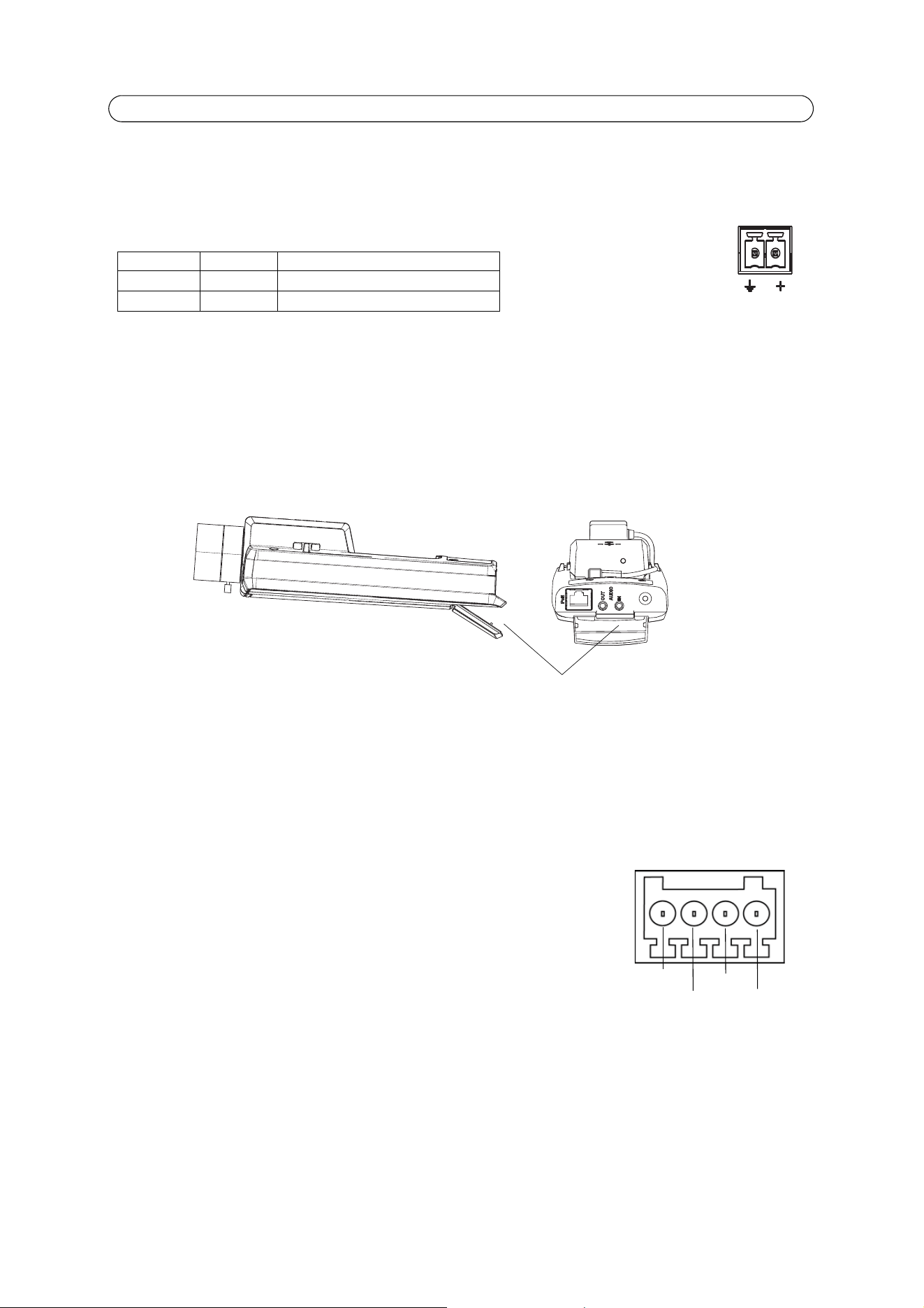
Unit connectors
Network connector - RJ-45 Ethernet connector. Supports Power over Ethernet. Using shielded cables is recommended.
Power connector - 2-pin terminal block used for power input.
Audio in (pink) – 3.5 mm input for a mono microphone, or a line-in mono signal (left channel is used from a stereo signal).
Audio out (green) – Audio output (line level) that can be connected to a public address (PA) system or an active speaker with
a built-in amplifier. A pair of headphones can also be attached. A stereo connector must be used for the audio out.
SD memory card slot - A standard or high capacity (SDHC) SD memory card can be used for local recording with removable
storage.
To insert an SD card, lift the SD card cover on the rear of the network camera, and carefully insert the SD card into its slot.
To remove an SD card lift the cover and gently push the card in and release it. The SD card will come out of the slot and can
be removed.
Note:
Before removing the SD card, it should be unmounted to prevent corruption of recordings. To unmount the SD card, go
to Setup > System Options > Storage > SD Card > Disk Management and click Unmount.
I/O terminal connector - Used in applications for e.g. motion detection, event triggering,
time lapse recording and alarm notifications. In addition to an auxiliary power and a GND
pin, it provides the interface to:
• 1 digital output - For connecting external devices such as relays and LEDs. Con-
nected devices can be activated by the VAPIX® Application Programming Interface,
output buttons on the Live View page or by an Event Type. The output will show as
active (shown under Events > Port Status) if the alarm device is activated.
• 1 digital input - An alarm input for connecting devices that can toggle between an
open and closed circuit, for example: PIRs, door/window contacts, and glass break detectors. When a signal is received
the state changes and the input becomes active (shown under Events > Port Status).
Notes:
• The I/O connector on AXIS P1346-E/AXIS P1347-E is connected to the housing electronics (fan/heater) at delivery, see
illustration under
Hardware Overview,
on page 5, and will trigger an input port event to indicate a fan or heater error
when activated. See
Events,
on page 29, for information on how to set up an event.
• For information on how to connect external devices, refer to the Installation Guide supplied with the product.
Function Pin number Description
GND 1 Ground
DC Power 2 Power input 8-20 V DC, max 9.6 W
1
2
SD memory card slot
Pin 3
Pin 4
Pin 2
Pin 1
Loading ...
Loading ...
Loading ...