
Loading ...
Loading ...
Loading ...
www.factorybuysdirect.com
7200247-01A
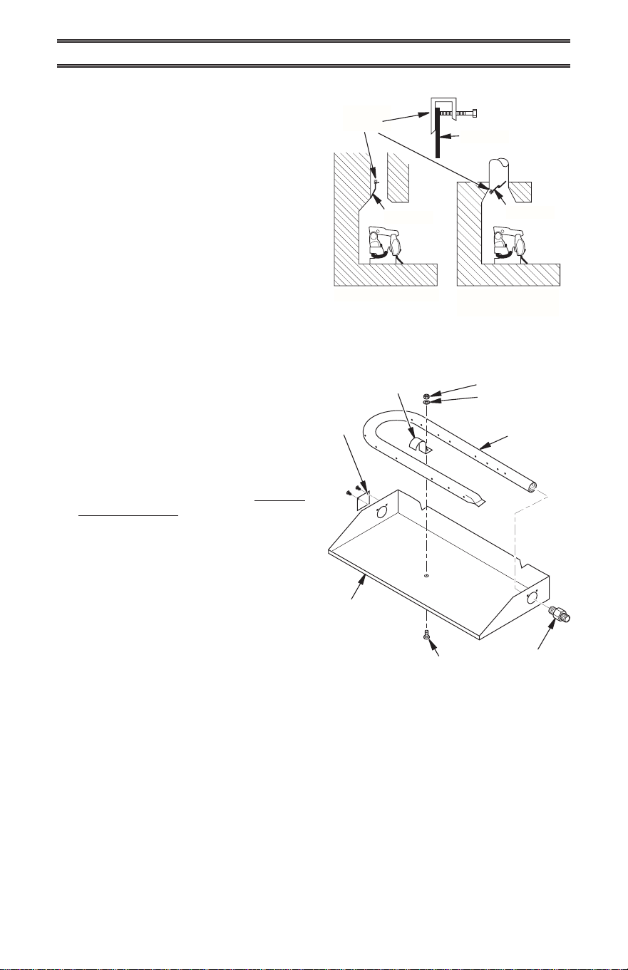
INSTALLING DAMPER CLAMP
Secure the damper stop clamp provided to
the leading edge of the damper as shown in
Figure 2. If for any reason this clamp doesn't
work on your replace, another suitable clamp
or permanent stop must be installed, or the
damper blade must be cut or removed.
The chimney damper must be FIXED in an
manner that will maintain the minimum per-
manent vent opening at all times.
INSTALLATION
Figure 2 - Attaching Damper Clamp
Masonry Fireplace
Manufactured
Fireplace
Damper
Damper
Damper
Damper
Clamp
HEARTH KIT ASSEMBLY
Note: The following instructions apply to
dual ame "U" style burners. Be sure all pipe
threaded connections are tight, and have
thread compound to prevent leaks.
1. Determine which side the gas line will be
coming into the replce.
Gas line is on the right side. This unit
is manufactured with the gas inlet on the
right side of the burner pan. See Connect-
ing to Gas Supply, page 8.
Gas line is on the left side. If your gas
line will be coming into the replace from
the left side, continue with step 2.
2. Using a screwdriver, remove cover plate
on left side of burner pan (see Figure 3).
3. Unscrew burner inlet tting from burner
manifold (see Figure 3).
4. Place burner manifold in pan with thread-
ed opening facing opening on left side.
5. Using thread sealant (resistant to the ac-
tion of natural gas) on larger end of tting,
screw the burner inlet tting through hole
and into burner manifold. Tighten using a
wrench.
6. Using burner clamp, screw, and nut pro-
vided, assemble clamp to pan. This will
hold the burner manifold in place.
7. Using screws removed in step 2, install
cover plate over opening on right side of
burner pan.
8. If using optional control system kit, follow
instructions included with kit for installa-
tion and operation.
Burner Pan
Assembly (Facing
Front of Fireplace)
Figure 3 - Installing Burner
Nut
Washer
Burner
Manifold
Burner
Clamp
Cover
Plate
Burner Inlet
Fitting
Screw
Loading ...
Loading ...
Loading ...