

FR GUIDE D’ASSEMBLAGETONDEUSE À RAYON DE BRAQUAGE ZÉRO
CRT426 / CRT428
P0803696-01, Rev B
EN
ZERO-TURN MOWER
OPERATOR MANUAL
ES CORTACÉSPED DE GIRO CERO
GUÍA DE MONTAJE
www.greenworkstools.com
www.greenworkscommercial.com

Greenworks hereby warranties this product, to the original purchaser with proof of purchase,
parts or workmanship. Greenworks, at its own discretion, will repair or replace any and all
parts found to be defective, through normal use, free of charge to the customer. This warranty
is valid only for units which have been used for personal use that have not been hired or
rented for industrial/commercial use, and that have been maintained in accordance with the
instructions in the owners’ manual supplied with the product from new.
ITEMS NOT COVERED BY WARRANTY:
1. Any that have been transferred to a new owner. This warranty only applies to the original
purchaser from an authorized Greenworks retailer or dealer. This warranty is non-
transferable.
2. Any part that has become inoperative due to misuse, rental use, commercial use, abuse,
alteration; or
3. If item has not been operated and/or maintained in accordance with the owner’s manual;
or
4. Normal wear
5. Routine maintenance parts or service include, but are not limited to: lubricants, mower
seat wear, blade sharpening, wheels, tiers, anti-scalp wheels, blades as well as any
optional accessories or attachments.
6.
7. Damage or failure resulting from, but not solely: immersion in water or other liquids,
accidents, misuse, neglect or lack of proper installation, and proper maintenance and
storage
8. An item that has not been registered on an authorized Greenworks website (see
REGISTRATION info with QR code or product page info for proper product registration).
REGISTRATION:
•
As the original owner, be sure to register your product (vehicle, batteries & chargers)
at following product pages on our Greenworks website(s):
MODEL VOLTAGE DESCRIPTION PRODUCT PAGES QR CODE
CRT426 60-volt
42” CrossoverT Tractor
Multi-Battery 6-in-Parallel
Kitted 60V
https://www.
greenworkstools.
com/pro-60v-42-inch-
crossover-t-7409002
CRT428 80-volt
42” CrossoverT Tractor
Multi-Battery 6-in-Parallel
Kitted 80V
https://www.
greenworkstools.
com/pro-80v-42-inch-
crossover-t-7409102
CRT428 82-volt
42” CrossoverT Tractor
Multi-Battery 6-in-Parallel
Kitted 82V
https://www.
greenworkscommercial.
com/pro-82v-42-inch-
crossover-t-7409202
• WARNING: To reduce the risk of injury, the user must read and understand the
Operator’s Manual before using this product. Save these instructions for future
reference.
•
online. Printed manuals can be out of date, so for latest tips and safety always check
the online manuals before using the machine.
• Troubleshooting guides are also online or in the app [link] which can be found in the
app store.
• Videos of uncrating, best practices, and routine maintenance can be found online.

HELPLINE:
Warranty service is available by calling our toll-free helpline, at
1-888-909-6757 Greenworks Pro
1-855-470-4267 Greenworks Commercial .
TRANSPORTATION CHARGES:
Transportation charges for the movement of any power equipment unit or attachment are the
responsibility of the purchaser. It is the purchase
r’s responsibility to pay transportation chares
for any part submitted for replacement under this warranty unless such return is requested in
writing by Greenworks.
USA Address: Greenworks Tools, PO Box 1238, Moorseville, NC 28115
Canada Address: Greenworks Tools Canada, PO Box 93095, Newmarket, Ontario, L3Y8K3
Greenworks Product Registration:
NAME: ____________________________________________________________________
ADDRESS: __________________________________________________________________
CIT
Y: _________ STATE: _________ ZIP CODE: _________ STATE COUNTRY: _________
HOME PHONE: _______________________ MOBILE PHONE: _______________________
PURCHASE DATE: ____________________ PURCHASED FROM:____________________
Please list Serial Number(s) below along with Model Information:
DESCRIPTION MODEL # PART # SERIAL #
DATE
PURCHASED

1 Risk levels...........................................4
2 Read all instructions......................... 4
2.1 Operator.............................................................4
2.2 Machine............................................................. 4
2.3 Mowing area......................................................5
2.4 Mowing..............................................................5
2.5 Servicing............................................................5
2.6 Child safety........................................................5
2.7 Use a ramp.........................................................6
2.8 Towing............................................................... 6
2.9 Battery and charger............................................6
3 Symbols on the product.................... 6
4 Environmentally safe battery
disposal...............................................7
5 Proposition 65....................................8
6 Description.........................................8
6.1 Purpose.............................................................. 8
6.2 Overview........................................................... 8
6.3 Control panel..................................................... 8
7 Installation......................................... 9
7.1 Unpack the machine.......................................... 9
7.2 Install the seat.................................................... 9
7.3 Install the steering wheel................................... 9
7.4 Install the accessories...................................... 10
8 Operation......................................... 10
8.1 Before operation.............................................. 10
8.2 Operate the machine........................................ 12
9 App operation tips...........................15
9.1 Mobile application...........................................15
9.2 Registration and Login.................................... 16
9.3 Add a device
.................................................... 18
9.4 GPS function....................................................19
10 Fault code.........................................22
11 Maintenance.....................................29
11.1 Tires................................................................. 29
11.2 Mower blade maintenance...............................29
11.3 Replace the headlight.......................................30
11.4 Lubrication.......................................................30
11.5 Torque values...................................................30
11.6 Battery pack maintenance................................30
11.7 Battery compartment filter maintenance......... 31
11.8 Service............................................................. 31
12 Transportation.................................32
13 Cleaning and storage.......................32
13.1 Clean the mower deck..................................... 32
13.2 Store the machine............................................ 33
13.3 Prepare for use after stoage............................. 33
14 Troubleshooting...............................34
15 Technical data..................................37
16 Warranty..........................................37
16.1 ITEMS NOT COVERED BY
WARRANTY:..................................................37
16.2 HELPLINE:.....................................................37
16.3 TRANSPORTATION CHARGES:..................37
17 Greenworks Product
Registration:.................................... 38
18 Serial Number(s)............................. 39
3
English
EN

1 RISK LEVELS
The following signal words and meanings are intended to
explain the levels of risk associated with this product.
SYM-
BOL
SIGNAL MEANING
DANGER Indicates an imminently haz-
ardous situation, which, if not
avoided, will result in death
or serious injury
.
WARNING Indicates a potentially hazard-
ous situation, which, if not
avoided, could result in death
or serious injury
.
CAUTION Indicates a potentially hazard-
ous situation, which, if not
avoided, may result in minor
or moderate injury
.
CAUTION
(Without Safety Alert Sym-
bol) Indicates a situation that
may result in property dam-
age.
2 READ ALL INSTRUCTIONS
WARNING
This symbol indicates important safety instructions. If these
instructions are not followed, it could endanger the personal
safety and/or property of the operator and others. Read and
understand all instructions in this manual before attempting
to operate the mower. Failure to comply with these
instructions may result in personal injury
.
DANGER
This mower was built to be operated according to the rules
for safe operation that are contained in this manual. As with
any type of power equipment, carelessness or error on the
part of the operator can result in serious injury. This mower
is capable of amputating body parts and throwing objects.
Failure to observe the following safety rules could result in
serious injury or death.
WARNING
Basic safety precautions should always be followed when
using lawnmowers in order to reduce the risk of fire,
electric shock, and personal injury
.
WARNING
Use of this mower should be restricted to individuals who
have read and understand and will follow the warnings and
instructions that are printed in this manual and on the
mower.
WARNING
•
Carefully read all instructions on the mower and in the
manual before attempting to assemble and operate the
mower.
•
For safe operation, read, understand, and follow all
instructions in this manual.
• Become familiar with all controls and their proper
operation. Know how to stop the mower and how to
disengage the power in an emergency.
• Keep this manual in a safe place for reference and
consult it regularly.
2.1 OPERATOR
• Do not use battery-operated ride-on mower in rain.
• Only allow responsible, capable adults who are familiar
with the instructions to operate this machine.
•
Safe operation requires your full attention and
capabilities.
• Always look where you are going and be aware of your
surroundings.
• Listen to the machine and be aware of any change.
• Feel the machine and its responses from both your inputs
and the environment.
• Remain focused on your task.
• Always wear proper eye protection that complies with the
latest safety standards in order to reduce the risk of eye
injury while operating or performing any adjustment or
repair. See ANSI Z87.1.
• Do not operate machine unless discharge guard or other
safety devices are in place and working.
• Always wear a face mask or a dust mask while operating
the mower in a dusty environment.
• Always dress properly. The wearing of protective gloves
and safety footwear is recommended.
• Do not wear radios or music headphones while operating
the machinery.
• Do not operate the equipment while wearing sandals,
tennis shoes, sneakers, shorts or any type of loose-fitting
clothing. Long hair, loose clothing or jewelry may get
tangled in moving parts. Always wear long pants, safety
glasses, ear protection and safety shoes while operating
this machine.
• Stay alert! Do not operate the mower when you are tired.
Do not operate the mower while under the influence of
alcohol or drugs. Pay attention to what you are doing. Use
common sense.
• Never carry passengers.
• Follow the manufacturer's recommendation for wheel
weights or counterweights.
2.2 MACHINE
• Never operate a poorly maintained machine.
•
Always keep safety shields and covers in place.
4
English
EN

• Follow daily and weekly checklists, making sure
electrical connections are secured and bolts are tightened.
• Replace damaged parts immediately
.
• Never operate mower without a proper trail shield,
discharge cover, switch control, or other safety device in
place and in working order. Do not operate the mower
with damaged safety devices; doing so can result in
injury.
• Repair or replace any damaged components before
restarting and operating the lawnmower.
• Only use approved replacement parts.
• Minimize exposure to water. Do not drive into water. Do
not leave in rain. Do not clean with pressurized water or
hose.
• Always store your lawnmower indoors. When not in use,
the mower should be stored indoors in a dry and locked
place, out of reach of children.
2.3 MOWING AREA
• Before mowing any area, thoroughly inspect the area for
any hazards. Walk the area to ensure there is adequate
traction and no holes, drop-of
fs, or hidden objects that
could cause issues. Clear the area of objects such as
rocks, wire, toys, etc., which could be thrown by the
blades.
• Be sure the area is clear of bystanders before operating.
Stop machine if anyone enters the area.
• Plan your mowing pattern in such a way as to avoid
discharging material toward roads, sidewalks, bystanders,
vehicles, windows, etc. Do not discharge material against
a wall or obstruction. Doing so may cause the discharged
material to ricochet back toward the operator.
• Do not mow anything but grasses.
• Stop the blades when crossing dirt, gravel, or paved
surfaces.
• Avoid dangerous environments. Do not operate the
mower in the rain or in wet or damp grass. To reduce the
risk of electric shock, do not expose to water or operate
on wet ground.
2.4 MOWING
• For riding mower models, always remain seated while
operating machine.
• Do not operate on inclines greater than 15 degrees.
•
Mow only in daylight or in good artificial light. Never
rush a mowing job.
• Never attempt high-speed maneuvering, especially in
crowded, congested areas or on slopes.
• In order to avoid contact with the blade or injury caused
by a thrown object, stay in the operating zone behind the
handles, and keep children and bystanders at least 100ft
(30m) away from the mower while it is in operation. Stop
the motor immediately if someone enters the mowing
area.
• Look down and behind before and while moving
backwards.
• Slow down before turning.
• Do not mow in reverse unless absolutely necessary
.
• When moving in reverse, SLOWLY pull right and left
Drive Control Levers rearward and avoid sudden
movements. Rapid movement of the Drive Control
Levers in either direction could result in a reaction of the
machine that can cause serious injury.
• Do not put hands or feet near rotating parts or under the
cutting deck. Contact with the blade can amputate hands
and feet.
• If the mower starts to vibrate excessively, stop the motor
and check for the cause immediately. Excessive vibration
is generally a sign the mower is not functioning properly.
• Stop the motor and wait until the blade comes to a
complete stop before unclogging the chute. The cutting
blade will continue to rotate for a few seconds after the
motor is shut off. Do not place any part of your body in
the blade area until you are sure that the blade has
stopped rotating.
• If lawnmower strikes a foreign object, stop the machine,
rotate the ignition switch to "OFF" position, then, if it is
safe, inspect for damage.
• Don't force the lawnmower.
• Do not use the mower for any job except that for which it
is intended.
2.5 SERVICING
• Turn off and remove key before servicing, cleaning, or
removing material from the ride-on mower.
•
Do not reach under blade guard. Keep hands, feet, and
clothing way from rotating blades.
• To reduce personal risk and damage to the machine, never
clean with pressure washer.
• Maintain your mower. Keep cutting edges sharp and
clean to ensure the best performance and safe operation.
2.6 CHILD SAFETY
Tragic accidents can occur if the operator is not aware of the
presence of children. Children are often attracted to the
machine and the mowing activity. Never assume that children
will remain where you last saw them.
•
Never leave machine unattended with key in switch,
especially with children present.
• Keep children out of the mowing area and under the
watchful care of a responsible adult other than the
operator.
• Do not allow children under the age of 14 to operate this
mower. Children who are 14 years of age and older must
read and understand the operating instructions and safety
rules in this manual, and must be trained and supervised
by a parent.
• Always disengage deck blade switch and turn key to
“OFF” position and remove key.
• Stay alert, and turn the mower off if a child or any other
person enters the mowing area.
5
English
EN

• Use extreme care when approaching blind corners,
doorways, shrubs, trees, or other objects that may obscure
your view of a child who may run into the path of the
mower.
•
Before and while backing, look behind and down for
small children.
• Never carry children on the mower with you, even with
the blade(s) shut off. They may fall off and be seriously
injured or interfere with safe machine operation. Children
who have been given rides in the past may suddenly
appear in the mowing area for another ride and be run
over or backed over by the machine.
2.7 USE A RAMP
• Use extreme caution when loading and unloading this
mower onto a truck or trailer with a ramp.
• Use only a single, full-width ramp. This provides a
surface for the mower frame to contact if the unit starts to
tip backwards. It also reduces the risk of a wheel going
of
f and the machine tipping over.
• Do not exceed a 15-degree angle between the ramp and
the ground or between the ramp and the trailer or truck.
• Become familiar with the mower’s controls and confident
in its smooth operation before attempting to drive it up or
down a ramp.
• Use slow drive mode and drive carefully.
• Avoid any sudden movement of the controls and use only
slow, even acceleration.
2.8 TOWING
• Tow only with a machine that has a hitch designed for
towing. Do not attach towed equipment except at the
hitch point.
• Follow the manufacturer
’s recommendation for weight
limits for towed equipment and towing on slopes.
• Never allow children or others in or on towed equipment.
• On slopes, the weight of the towed equipment may cause
loss of traction and loss of control.
• Travel slowly and allow extra distance to stop.
2.9 BATTERY AND CHARGER
• Prevent unintentional starting. Ensure the switch is in the
of
f-position before connecting to battery pack, picking up
or carrying the appliance. Carrying the appliance with
your finger on the switch or ener
gizing appliance that
have the switch on invites accidents.
• Disconnect the battery pack from the appliance before
making any adjustments, changing accessories, or storing
appliance. Such preventive safety measures reduce the
risk of starting the appliance accidentally.
• Recharge only with the charger specified by the
manufacturer. A charger that is suitable for one type of
battery pack may create a risk of fire when used with
another battery pack.
• Use appliances only with specifically designated battery
packs. Use of any other battery packs may create a risk of
injury and fire.
• When battery pack is not in use, keep it away from other
metal objects, like paper clips, coins, keys, nails, screws
or other small metal objects, that can make a connection
from one terminal to another
. Shorting the battery
terminals together may cause burns or a fire.
• Under abusive conditions, liquid may be ejected from the
battery; avoid contact. If contact accidentally occurs,
flush with water. If liquid contacts eyes, additionally seek
medical help. Liquid ejected from the battery may cause
irritation or burns.
• Do not use a battery pack or appliance that is damaged or
modified. Damaged or modified batteries may exhibit
unpredictable behavior resulting in fire, explosion or risk
of injury.
• Do not expose a battery pack or appliance to fire or
excessive temperature. Exposure to fire or temperature
above 130°C may cause explosion. The temperature of
130°C can be replaced by the temperature of 265°F.
• Follow all charging instructions and do not charge the
battery pack or appliance outside of the temperature range
specified in the instructions. Charging improperly or at
temperatures outside of the specified range may damage
the battery and increase the risk of fire.
• Have servicing performed by a qualified repair person
using only identical replacement parts. This will ensure
that the safety of the product is maintained.
• Do not modify or attempt to repair the appliance or the
battery pack (as applicable) except as indicated in the
instructions for use and care.
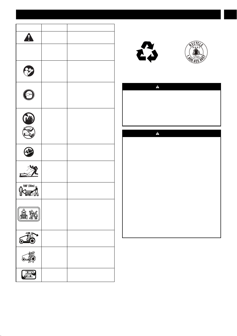
3 SYMBOLS ON THE PRODUCT
Some of the following symbols may be used on this tool.
Please study them and learn their meaning. Proper
interpretation of these symbols will allow you to operate the
tool better and safer
.
Symbol Name Explanation
V Volt Voltage
A Amperes Current
Hz Hertz
Frequency (cycles per sec-
ond)
W Watt Power
min Minutes Time
/min Per Minute
Revolutions, strokes, sur-
face speed, orbits etc., per
minute
Direct Current
Type or a characteristic of
current
n
o
No Load
Speed
Rotational speed, at no load
6
English
EN
Symbol Name Explanation
Safety Alert
Precautions that involve
your safety
.
IPX4
Ingress Pro-
tection De-
gree
Protection from splashing
water.
Read Opera-
tor’
s Manual
To reduce the risk of injury,
user must read and under-
stand operator’s manual be-
fore using this product.
Eye Protec-
tion
Always wear eye protection
with side shields marked to
comply with ANSI Z87.1
when operating this equip-
ment.
DANGER ---
Keep Hands
and Feet
Away
T
o reduce the risk of injury,
keep hands and feet away
from rotating parts. Do not
operate unless discharge
cover or grass bag is in its
proper place. If damaged,
replace immediately.
DANGER ---
Steep Slope
Hazard
Use extra caution on slopes.
do not mow slopes greater
than 15 degrees.
DANGER ---
Thrown Deb-
ris
Remove objects that can be
thrown by the blade in any
direction. Wear safety
glasses.
DANGER ---
Keep By-
standers Away
Keep all bystanders at least
100 ft. away.
DANGER ---
Keep By-
standers Away
Keep the area of operation
clear of all bystanders, par-
ticularly small children.
Stop the machine and at-
tachment(s) if anyone en-
ters the area.
Look around Always look where you are
going and be aware of your
surroundings.
Keep children
away
Never carry children on the
mower with you. Keep chil-
dren and animals out of the
mowing area.
No Reach Do not reach hands or feet
under mower deck.
4 ENVIRONMENTALLY SAFE
BATTERY DISPOSAL
The toxic and corrosive materials below are in the batteries
used in this machine: Lithium-Ion, a toxic material.
WARNING
Discard all toxic materials in a specified manner to prevent
contamination of the environment. Before discarding
damaged or worn out Li-ion battery
, contact your local
waste disposal agency
, or the local Environmental
Protection Agency for information and specific instructions.
Take the batteries to a local recycling and/or disposal center,
certified for lithium-ion disposal.
WARNING
If the battery pack cracks or breaks, with or without leaks,
do not recharge it and do not use. Discard it and replace
with a new battery pack. DO NOT TRY TO REPAIR IT! To
prevent injury and risk of fire, explosion, or electric shock,
and to avoid damage to the environment:
• Cover the terminals of the battery with heavy-duty
adhesive tape.
• DO NOT try to remove or destroy any of the battery
pack components.
• DO NOT try to open the battery pack.
• If a leak develops, the released electrolytes are
corrosive and toxic. DO NOT get the solution in the
eyes or on skin, and do not swallow it.
• DO NOT put these batteries in your regular household
trash.
• DO NOT incinerate.
• DO NOT put them where they will become part of any
waste landfill or municipal solid waste stream.
• Take them to a certified recycling or disposal center.
7
English
EN
5 PROPOSITION 65
WARNING
This product contains a chemical known to the state of
California to cause cancer, birth defects or other
reproductive harm. Some dust created by power sanding,
sawing, grinding, drilling, and other construction activities
contains chemicals known to cause cancer
, birth defects or
other reproductive harm. Some examples of these chemicals
are:
• Lead from lead-based paints;
• Crystalline silica from bricks and cement and other
masonry products;
• Arsenic and chromium from chemically treated lumber.
Your risk of exposure to these chemicals varies depending
on how often you do this type of work. To reduce your
exposure to these chemicals, work in a well-ventilated area,
and work with approved safety equipment, such as dust
masks that are specially designed to filter out microscopic
particles.
Save these instructions.
6 DESCRIPTION
6.1 PURPOSE
This machine is used for domestic lawn mowing. The cutting
blade should be parallel to the ground. All four wheels must
touch the ground while mowing.
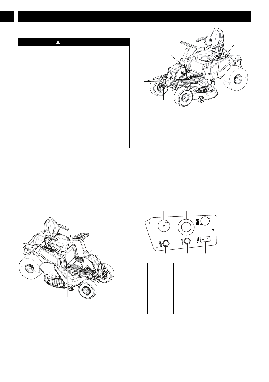
6.2 OVERVIEW
1
5
2
4
6
7
3
9
10
11
8
1
Seat adjustment lever
2
Side discharge chute
3
Brake pedal
4
Control panel
5
Deck height adjustment lever
6
Accelerator pedal
7
Parking brake bar
8
Headlights
9
Cup holder
10
USB port
11
ETO socket (2" X 2")
6.3 CONTROL PANEL
6.3.1 CONTROL PANEL
# Name Function
1 Power
switch with
start key
The power switch is used to turn the
mower on and off. The start key must be
inserted before the switch can be operat-
ed.
2
Digital dis-
play
This display shows important electrical
system information. Refer to the Electri-
cal section for complete information.
8
English
EN
# Name Function
3 PTO switch Pull the PTO switch up to activate the
mower’
s cutting blades. Push the knob
down to stop the cutting blades.
NOTE
For cutting in reverse, the reverse
mode button must also be activated.
4 Direction
control but-
ton
The direction of movement of the mower
is controlled using the direction control
switch. Available settings are forward (F)
and reverse (R).
5 Cruise con-
trol button
The cruise control button allows you to
continue forward at a set speed without
needing to press the accelerator pedal.
6 Reverse
mode button
Press the reverse mode button to allow
the mower to cut when maneuvering in
the reverse direction. The blades will not
work if mower is operated in reverse
without pressing the reverse mode but-
ton.
NOTE
The PTO switch must also be pulled up
for mowing to occur when maneuver-
ing in reverse.
7 INSTALLATION
WARNING
Do not use accessories that are not recommended by the
manufacturer.
W
ARNING
Do not put in the safety key or the battery pack until you
finalised the assembly of all the parts.
7.1 UNPACK THE MACHINE
WARNING
Make sure that you correctly assemble the machine before
use.
WARNING
•
If parts of the machine are damaged, do not use the
machine.
•
If you do not have all the parts, do not operate the
machine.
•
If parts are damaged or missing, contact the service
center.
1. Open the package.
2. Read the documentation provided in the box.
3.
Remove all the unassembled parts from the box.
4.
Remove the machine from the box.
5.
Discard the box and packing material in compliance with
local regulations.
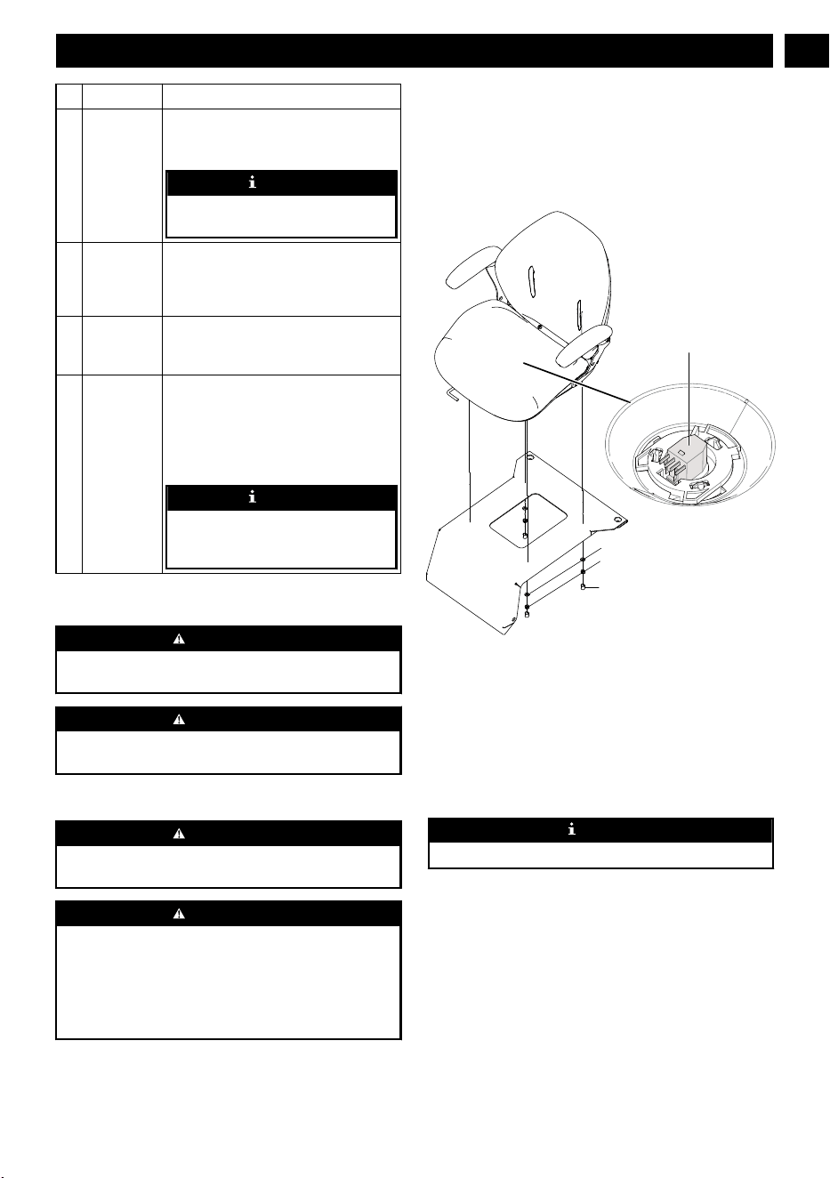
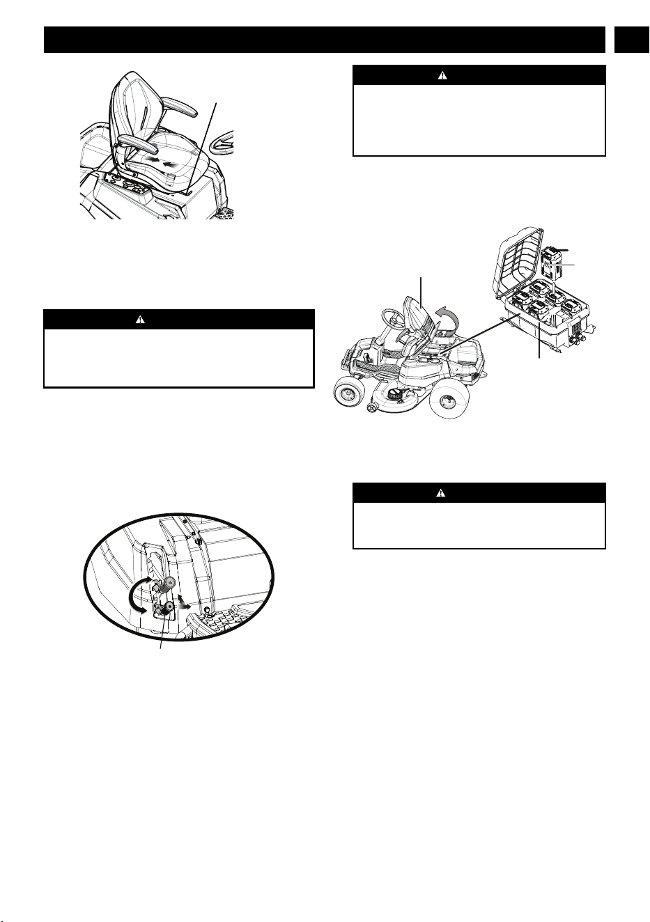
7.2 INSTALL THE SEAT
Sleeve
Nut
W
asher
Seat plug
1. Place the seat assembly over the mounting brackets and
align holes as shown.
2. Connect the seat plug to the machine.
3.
Install the washers and nuts and tighten securely.
4. Attach the sleeve to the nut.
5. Make sure it is securely seated.
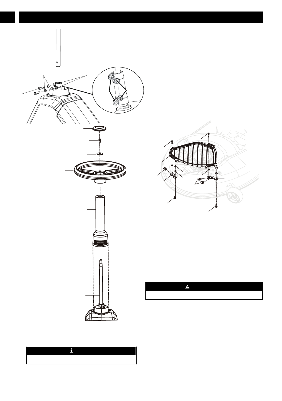
7.3 INSTALL THE STEERING WHEEL
NOTE
Make sure the slot faces up to the seat.
9
English
EN
Bolt holes
13.2ft.lbs
18.4ft.lbs
W
ashers
Bolts
Hole
Steering shaft
Model cover plate
Bolt
Washer
Steering wheel
Steering column
Slot
Steering shaft
1. Install the steering shaft into the coupler, rotating as
needed to align hole in shaft with bolt hole in coupler
.
2.
Install two bolts and tighten securely.
NOTE
Torque bolts to the value as shown.
3. Install the steering column. Note the tabs on the bottom
of the steering column that fit into the holes in the
opening and make sure steering column is securely
seated.
4. Make sure the mower
’s wheel is pointed straight ahead,
then install the steering wheel over the steering column
with force.
5. Install the bolt and washer; tighten securely.
6. Install the steering wheel cover plate.
7.4 INSTALL THE ACCESSORIES
1. Mulch cover
7.4.1 INSTALL THE MULCH COVER
Bolt
Bolt
Bolt
Nut
Nut
Nut
W
asher
Bracket
Bracket
Bearing ring
Mulch cover
Bolt
The mower is configured for side discharge when shipped. If
mulching is desired:
1. Place the mulch cover on the tab on the mower housing.
2.
Align the holes in the mulch cover and the holes in the
mower housing.
3. Install and tighten the bolts, screws, fixation clamps and
bearing ring as shown.
8 OPERATION
WARNING
W
ear eye protection during operation.
8.1 BEFORE OPERATION
8.1.1 ADJUST THE SEAT
Adjust the seat position to ensure you are able to make firm
contact with the accelerator and brake pedals before operating
the mower.
10
English
EN
seat adjustment lever
1. Sit down on seat and lift the seat adjustment lever.
2. While holding the lever
, slide the seat to the desired
position.
3. Release the lever and make sure the seat is locked in
position before operating the mower.
WARNING
Be sure the seat is locked into place before operating the
mower. A seat that is not secure can cause the operator to
shift and lose control of the mower and result in possible
death or serious personal injury
.
8.1.2 ADJUST THE DECK CUTTING
HEIGHT
Before using the mower, raise the deck height to the cutting
position best suited for your lawn.
Deck height is adjustable from 1.5-4.5" inches. Deck should
be raised while mowing is in progress to avoid stumps, rocks
or other obstacle that can be damage mower deck.
Deck height adjustment lever
1. Stop the mower and disengage blades.
2. T
urn key to OFF position and set the parking brake.
3. To raise the cutting deck, grasp the deck height
adjustment lever, push left to disengage from slot, move
toward the back of the mower, then push right into slot to
secure.
4. To lower the cutting deck, grasp the deck height
adjustment lever, push left to disengage from slot, move
toward the front of the mower, then push right into slot to
secure.
CAUTION
Hold the deck height adjustment lever firmly when
setting the deck height and only release when it is
secure in the desired slot. Quickly letting go of the lever
may create a pinching or pulling hazard to the
operator’s hand.
8.1.3 INSTALL THE BATTERY PACK
To verify mower batteries are fully charged, check the battery
level indicator. See the battery manual for more details.
Seat
Battery
Battery
compartment
Battery
latch
1. Lift the seat panel.
2. Lift the battery compartment cover.
3. Install the battery pack into the battery compartment.
WARNING
Align the ribs of the battery with the battery port. Make
sure that the battery latch clicks into the battery
compartment smoothly.
8.1.4 BEFORE OPERATING THE MACHINE
• Ensure work area is clear of children, bystanders, and
pets.
• Clear the work area of objects that may be thrown by the
mower blades.
•
Check brake operation.
• Check tire pressure.
• Check for loose fasteners.
• Check to make sure all guards are in place and working
properly.
• Clean debris from mower.
• Test safety interlock system.
• Adjust seat to desired position.
• Verify battery charge level.
11
English
EN
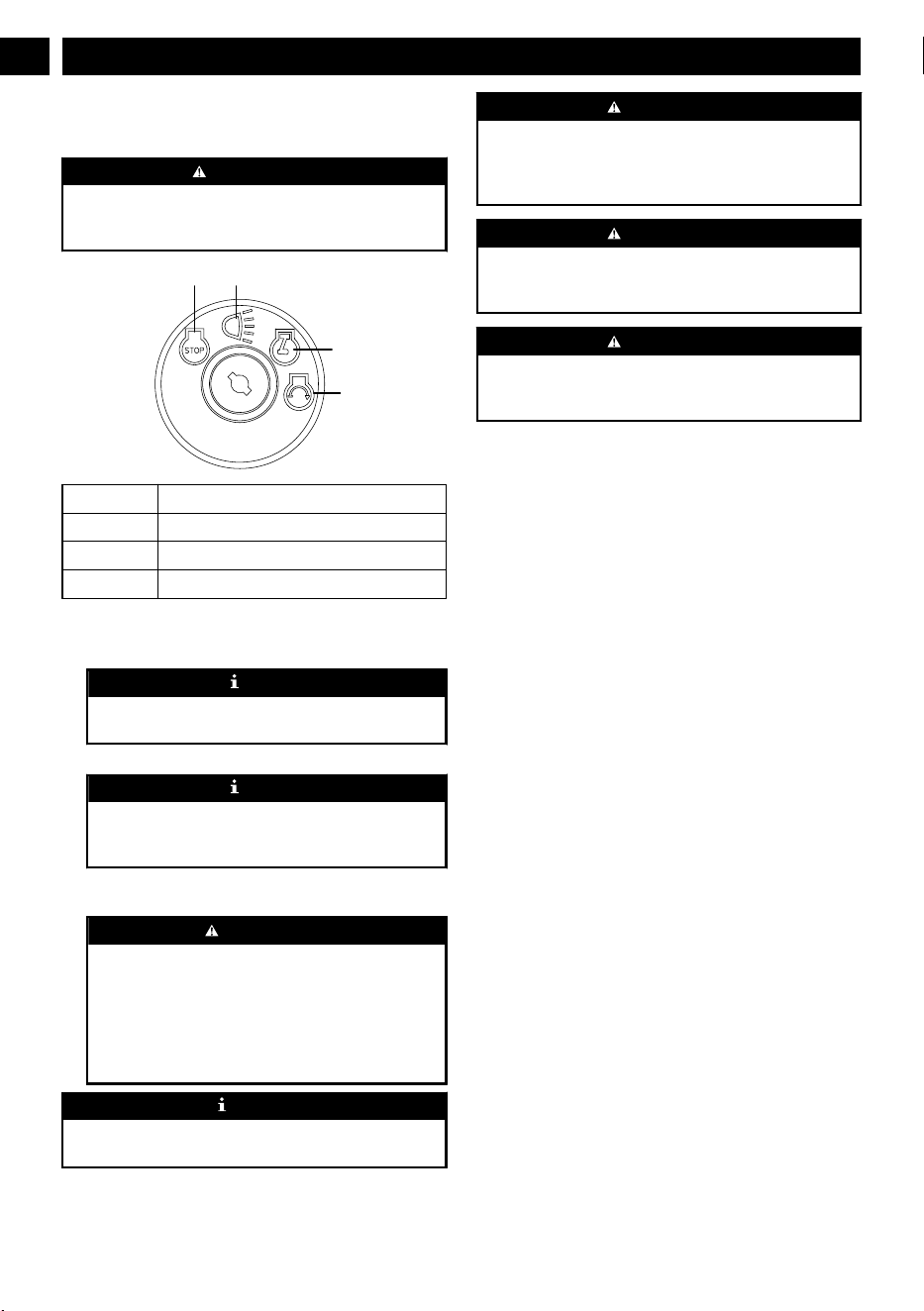
8.2 OPERATE THE MACHINE
8.2.1 START THE MACHINE
WARNING
Clear the area of bystanders before operating the mower
. If
anyone enters the mowing area, stop immediately and do
not return to mowing until the bystanders leave the area.
a b
c
d
a Stop / Off
b On (with lights)
c Run
d Start
1. Raise the mower deck to its highest position.
2.
Insert start key and turn to start position (d).
NOTE
The key will return back to (c) position automatically.
W
ait for 4 seconds until the display shows normally
.
3. Release the parking brake.
NOTE
The buzzer alarms for one time, the machine is READY
T
O GO, then you can drive the machine even without
blade working.
4. Place steering control levers in forward (F) position and
drive to desired mowing location.
W
ARNING
Be certain you have correctly set your intended
direction of travel with the direction control button
before pressing the accelerator pedal. Failure to do so
could result in you driving the mower in an unintended
direction, which could cause loss of control or an
accident resulting in death, serious personal injury, or
property damage.
NOTE
Turn the headlight on by turning the key to the postion (b)
when you power on the machine.
WARNING
Use caution when crossing over gravel paths or driveways.
Before crossing, disengage the blades and raise the cutting
deck to the highest position to minimize the possibility of
ricochet. Drive slowly to avoid loss of traction and control.
WARNING
Do not attempt to change the direction of operation while
the mower is in motion. Always come to a complete stop
before changing the mower direction.
WARNING
Steering control levers will spring back towards neutral
position if you release them, but you still need to control
them manually to reach neutral position.
8.2.2 STOP THE MACHINE
1. Stop mower on a flat, level surface.
2. Set the parking brake.
3.
Push the PTO switch down to turn blades off.
4. Turn the key to OFF position (a).
8.2.3 SET THE CRUISE CONTROL
Cruise control allows the mower to remain at a constant speed
without the operator having to maintain pressure on the
accelerator pedal. It should only be used in the forward
position on relatively smooth, straight surfaces, and should
never be used on slopes or rough terrain.
8.2.3.1 SET THE CRUISE CONTROL
1. While driving the mower forward, press the accelerator
pedal until the desired rate of speed is achieved.
2. Press the cruise control button. The light around the
button will illuminate to show cruise control is active.
3. Release pressure on the accelerator pedal. Mower speed
should remain constant.
8.2.3.2 RELEASE THE CRUISE CONTROL
1. Tap on the accelerator pedal, depress the brake pedal, or
press the cruise control button again.
8.2.4 SET THE PARKING BRAKE
1. Fully depress and hold the brake pedal.
2. Push the parking brake lever all the way down untuil it
engage into the slot.
3.
Release the brake pedal.
12
English
EN
WARNING
Never leave the mower unattended when the motor is
running. Verify that the parking brake is set and the key has
been removed. Failure to set the parking brake could cause
the mower to move, and leaving the key could allow
unauthorized use that could result in serious personal injury.
8.2.5 REVERSE MODE OPERATION:
• Depress the brake pedal and bring the mower to a
complete stop.
• Push the PT
O switch down to turn blades off.
• Place direction control switch in reverse (R) position.
• Raise the PTO switch, slowly press accelerator pedal, and
reverse mow as needed.
• Keep pressing the reverse mode button to activate the
blade.
WARNING
Do not mow in reverse unless absolutely necessary. Always
look down and behind before and while backing to make
sure no children, bystanders, or pets enter the mowing area.
Be aware that the reverse mode operation is activated when
the reverse mode button is illuminated in green. Remember
that a careless fraction of a second is suf
ficient to inflict
death or serious injury
.
WARNING
Be especially careful before and when backing with the
bagger kit (not provided) installed, as it may limit visibility
.
Always look closely behind and down for small children,
bystanders, and pets and move the mower slowly to prevent
back over accidents that can cause death or serious personal
injury
.
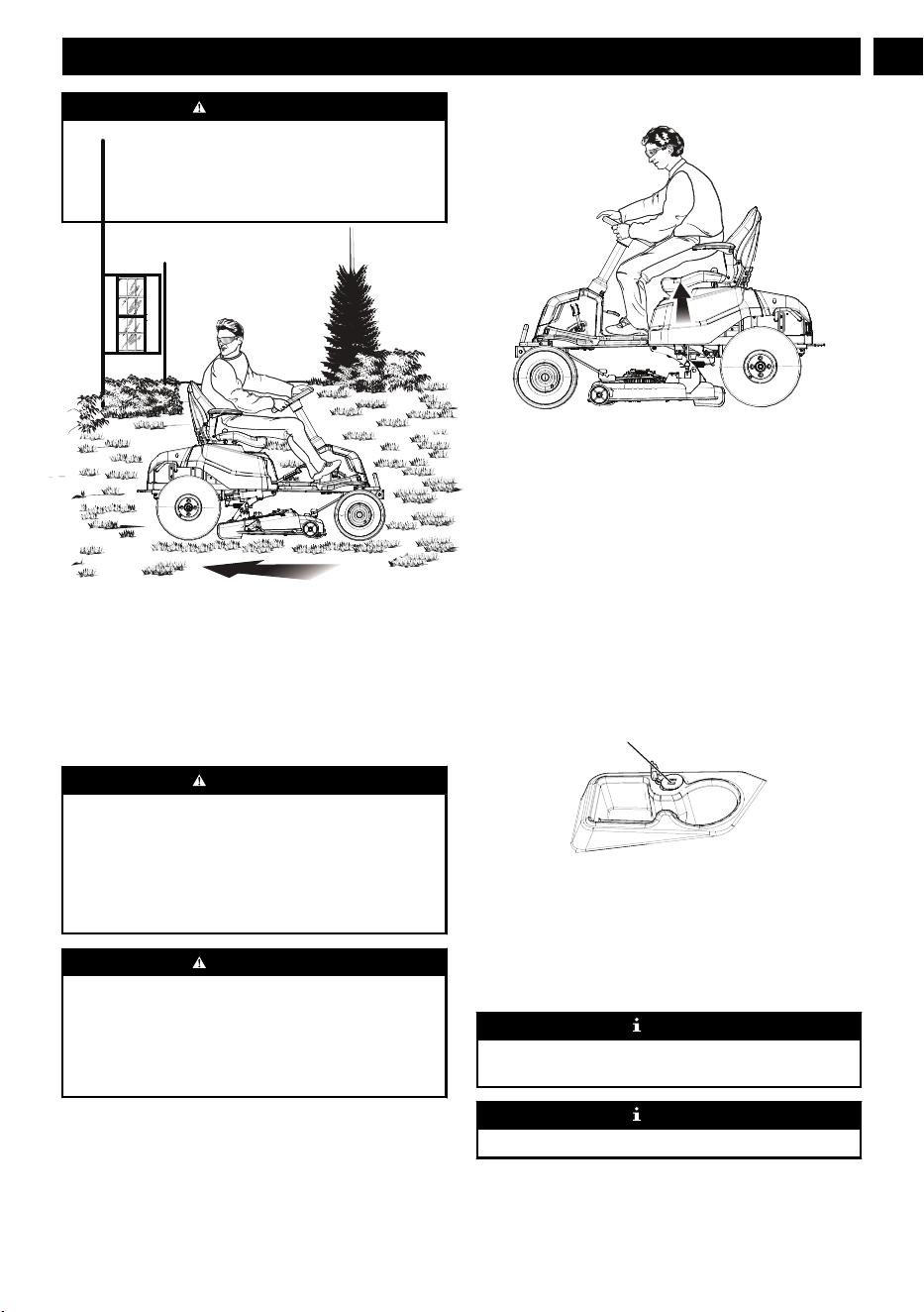
8.2.6 SAFETY INTERLOCK SYSTEM
This mower features a Safety Interlock System to protect the
operator by shutting off the blades if the operator leaves the
seat with the blades running. T
est the system before each use
to be sure it is working correctly.
1. Make sure direction control switch is in neutral (N)
position and PTO switch is down.
2. Install start key and turn to start position.
3. Raise the PTO switch to activate blades.
4. Briefly lift off the seat, but do not get off the mower.
The blades should shut off within 5 seconds. If they don’t,
contact customer service. Do not operate the mower until the
safety interlock system has been repaired.
8.2.7 USE THE USB PORT
USB port
The USB charging port provides charging power of 5 Volts
DC at up to 2.1 amps for your cell phone, MP3 player, or
other USB devices. Consult the owner
’s manual for your
device for specific charging requirements.
Connect one end of a USB cable (not provided) to your
device and the other end to the USB charging port on the
mower, to begin charging your device.
NOTE
Attempting to charge devices rated more than 2.1 amps
could damage the USB charging port and/or the mower
.
NOTE
The USB port is only powered when the machine starts.
13
English
EN
WARNING
Never use headphones or any electronic device, such as a
smart phone or tablet, while operating the mower.
Distracted operation can result in an accident that could
result in death or serious personal injury to the operator or a
bystander.
8.2.8 OPERATION TIPS
• Keep mower blades sharp.
• Make sure the lawn is clear of stones, sticks, wires, toys,
tree nuts, tree branches, and other objects that could
damage the lawn mower blades or motor
. Do not mow
over property stakes or other metal posts. Such objects
could damage the blade or be accidentally thrown by the
mower in any direction and cause serious personal injury
to the operator and others.
• For a healthy lawn, always cut off one-third or less of the
total length of the grass.
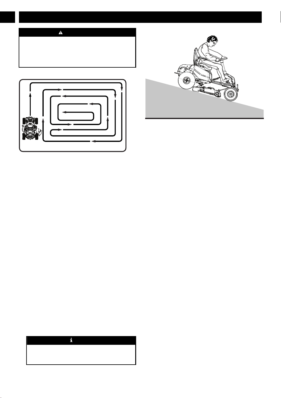
• When mowing large areas, start by turning to the right so
that clippings will discharge away from shrubs, fences,
driveways, etc. After one or two rounds, mow in the
opposite direction, making left hand turns until finished.
• Mow so that discharged clippings exit in the direction of
the lawn area that has already been cut.
• When cutting heavy grass, reduce speed to allow for more
effective cutting and a proper discharge of the clippings.
• During normal mowing, cut only about 1.5" of the grass
blade. Cutting more than that is not recommended unless
grass is sparse or it is the end of the mowing season.
• Do not cut wet grass. It will stick to the underside of the
deck and prevent proper bagging or mulching of grass
clippings.
• New or thick grass may require a narrower cut or a higher
cutting height.
• Keep the mower deck and side discharge chute clean.
Remove grass clippings, leaves, dirt, and any other
accumulated debris before and after each use. Do not
spray with a garden hose to clean.
NOTE
Always stop mower, allow blades to completely stop,
and remove the start key before cleaning underneath the
mower.
8.2.9 SLOPE OPERATION
Slopes are a major factor related to loss of control and tip-
over accidents, which can result in severe injury or death.
Operation on all slopes requires extra caution. If you cannot
back up the slope or if you feel uneasy on it, do not mow it.
• Travel in the manufacturer recommended direction on
slopes. Use caution while operating near drop-offs.
• Do not operate machine under any condition where
traction, steering, or stability is in question. Tires could
slide even if the wheels are stopped.
• Always keep the machine in gear when going down
slopes. Do not coast downhill.
• Mow up and down slopes, not across.
• Watch for holes, ruts, bumps, rocks, or other hidden
objects. Uneven terrain could overturn the machine. Tall
grass can hide obstacles.
• Do not mow near drop-offs, ditches or embankments. The
machine could suddenly roll over if a wheel goes over the
edge or if the edge caves in.
• Choose a low ground speed so you will not have to stop
or shift while on a slope.
• Do not mow on wet grass. Tires may lose traction.
• Avoid starting, stopping, or turning on a slope. If the tires
lose traction, disengage the blade(s) and proceed slowly
straight down the slope.
• Keep all movement on slopes slow and gradual. Do not
make sudden changes in speed or direction, which could
cause the machine to roll over.
• Use extra care while operating machine with attachments;
they can affect the stability of the machine. Do not use on
steep slopes.
• If using the optional bagger kit, use extreme caution and
operate the mower slowly when operating on slopes, as
the bagging kit can change the stability of the mower.
• Always use the brakes when travelling down the slope.
Do not attempt to let the mower coast downhill in neutral.
8.2.10 DIGITAL DISPLAY
The function of the digital display, located on the control
panel, is to provide electrical system information to the
14
English
EN
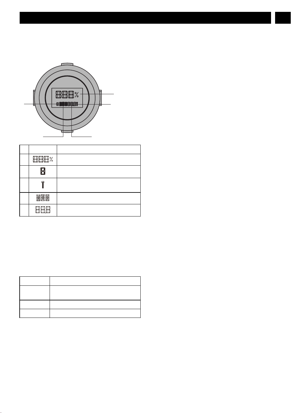
operator. It gives detailed information in the form of pattern,
codes and number.
8.2.10.
1
DIGITAL DISPLA
Y
1
3
54
2
# Name Meaning
1 Battery remaining capacity
2 Time signal
3 Controller fault/ battery fault/ motor
fault/ vehicle fault
4 Fault position
5 Fault code/ total working hours
8.2.11 FAULTS
The Canbus system will take action to protect the user and
machine when it detects an issue. When it acts to turn of
f the
machine or a component, it will indicate that a fault has
occurred, and that fault will be shown on the digital display
.
All electrical faults have a letter code followed by a number.
The first letter describes the system that caused the fault
according to this chart:
T Traction Controller and motor
PMU Power management unit (in the battery cab-
in)
MR Right Blade Controller and motor
ML Left Blade Controller and motor
9 APP OPERATION TIPS
9.1 MOBILE APPLICATION
Find the serial number, pairing code and QR code in the vehicle matching label on your QUICK START GUIDE.
15
English
EN

Pairing code
Serial number
QR code
9.2 REGISTRATION AND LOGIN
Scan the QR code and download the app and login in.
Step 1. Create an account and then log in.
Step 2. Fill in the registration information (with * is required),
and then click the "next“ button.
16
English
EN

Step 3. Confirm User Rights.
Confirm End User License Agreement.
Step 4.1. Activate the account email, click "Continue". Step 4.2. Open the email and click "Click here" to get to the
log in interface.
17
English
EN

Step 5. Log in.
9.3 ADD A DEVICE
Step 1. Add a device of Greenworks tools.
Step 2. Find category of vehicle according to your device type,
then click button “Pair” (Vehicle).
18
English
EN

Step 3. Paring by entering serial number + Paring code (Own-
er).
Step 4. When you select option “pair manually”, just manually
input Serial Number + Paring Code
Step 5. Review device license agreement and sign it.
9.4 GPS FUNCTION
1. Upload data
Connect your mobile phone to the APP, and you can check fault, speed, and battery power of the machine through the APP.
19
English
EN

2. GPS
The machine is equipped with GPS function, you can connect your mobile phone to the machine by the APP. It is convenient to
locate your machine and achieve anti-theft ef
fect.
20
English
EN

This icon shows the position where the vehicle was last con-
nected on map.
When click vehicle icon, it will show the device’s name, latest
latitude and longitude.
Click the copy icon to copy the value of latitude and longitude.
WARNING
The 4G & GPS connectivity device may lose the GPS satellite signal or cellular connection at any time. Due to heavy tree
canopies, lar
ge buildings, poor weather conditions, electrical interference, dead zones, or other obstacles.
21
English
EN

10 FAULT CODE
Display Description Status code Cause Solution
CAN communica-
tion failure
CAN communica-
tion of left blade
controller is abnor
-
mal.
V12
CAN communica-
tion failure.
Contact the service
center for help.
The communica-
tion module of the
left blade controller
is damaged.
The left blade con-
troller fails.
Contact the service
center for help.
CAN communica-
tion of right blade
controller is abnor-
mal.
V13
CAN communica-
tion failure.
Contact the service
center for help.
The communica-
tion module of the
right blade control-
ler is damaged.
The right blade
controller fails.
Contact the service
center for help.
PMU CAN com-
munication is ab-
normal.
V21 Contact the service
center for help.
The machine does
not work when
powered on.
The initial value of
the throttle exceeds
1.1V
.
V15 There is grass at
the initial limit of
the accelerator ped-
al.
Open the front cov-
er and clean up the
grass.
The cruise control
switch is working.
The position of
switch is not cor-
rect.
Check whether the
cruise control
switch is stuck.
The neutral bypass
knob is engaged.
The position of
switch is not cor-
rect.
Depress the park-
ing pedal to park.
Y
ou pull up on the
PTO switch.
The position of
switch is not cor-
rect.
Press the knife start
switch.
The accelerator
pedal is depressed.
The accelerator
pedal is not in the
initial position.
Put the accelera tor
pedal in position.
22
English
EN

Display Description Status code Cause Solution
Operation sequence
failure
After the vehicle
self-inspection
function, the seat
switch is not work-
ing (when the per-
son is not in the
seat), and it is de-
tected that the
blade switch signal
is in the activated
state.
V16
After the vehicle
self-check function,
the seat switch is
not working (when
the operator is not
in the seat), and the
PTO switch is in
the ON state.
Activate the PT
O
switch.
After the vehicle
self-check function
is over, the seat
switch is not work-
ing (when the per-
son is not in posi-
tion), and the accel-
erator is not in the
dead zone.
After the vehicle
self-check function
is over, the seat
switch is not work-
ing (when the per-
son is not in posi-
tion), and the accel-
erator is not in the
dead zone.
Release the acceler-
ator pedal.
Press the reverse
button before mow-
ing in reverse.
Wrong sequence of
operations.
Press the PTO
switch and release
the accelerate ped-
al.
The reverse allow
button is not activa-
ted when you press
the accelerator after
the reverse button
pressed.
Wrong sequence of
operations.
Press the PTO
switch and release
the accelerate ped-
al.
The operator leaves
the seat for more
than 1S when
mowing.
Wrong sequence of
operations.
Press the PTO
switch and release
the accelerate ped-
al.
Throttle failure
The connector of
the potentiometer is
loose.
V18
Loose connector.
Contact the service
center for help.
Potentiometer fail-
ure.
Potentiometer fail-
ure.
Contact the service
center for help.
The battery com-
partment cover is
abnormal.
The battery com-
partment cover is
not locked when
the seat switch is
connected (the op-
erator is in the
seat).
V27
The battery com-
partment cover is
not locked.
Contact the service
center for help.
23
English
EN

Display Description Status code Cause Solution
The drive motor
does not work.
"A high-voltage
battery pack is in-
serted in the PMU."
T11
Wrong battery pack
applied. Check the
battery pack.
Check the battery
pack.
A low-voltage bat-
tery pack is inser-
ted in the PMU.
T12
W
rong battery pack
applied. Check the
battery pack.
Check the battery
pack.
The power of the
battery pack in the
PMU of the battery
compartment is too
low.
The battery capaci-
ty is not high
enough.
The drive motor
current is too high.
T13
The drive motor
current is too high.
Contact the service
center for help.
The gearbox is
stuck.
T14
The right gearbox
fails.
Contact the service
center for help.
The 6pin connector
between the drive
motor and the drive
controller is loose.
T15/T21
The connector is
loose.
Contact the service
center for help.
The drive control-
ler temperature is
too high.
T17
The controller tem-
perature is too
high.
Power off the ma-
chine, and power
on again after the
controller cools
down for a while.
The drive motor
temperature is too
high.
T18
The drive motor
temperature is too
high.
Power off the ma-
chine, and power
on again after the
drive motor cools
down for a while.
24
English
EN

Display Description Status code Cause Solution
Blade failure
Poor contact of seat
switch.
V27 Seat switch fails.
Contact the service
center for help.
A high-voltage bat-
tery pack is inser-
ted in the battery
compartment.
ML1
1
Battery pack is not
applicable.
Check the battery
pack.
A high-voltage bat-
tery pack is inser-
ted in the battery
compartment.
MR11
Battery pack is not
applicable.
Check the battery
pack.
A low-voltage bat-
tery pack is inser-
ted in the battery
compartment / bat-
tery pack voltage is
low.
ML12
Battery pack is not
applicable.
Check the battery
pack.
A low-voltage bat-
tery pack is inser-
ted in the battery
compartment / bat-
tery pack voltage is
low.
MR12
Battery pack is not
applicable.
Check the battery
pack.
The left mowing
motor is overloa-
ded.
ML13/ML14
Motor stall protec-
tion.
Increase the deck
height and reduce
the drive speed.
The inside of the
deck header is
blocked by grass
and debris.
Clear the deck
The blade hit a
hard object.
Restart the ma-
chine.
25
English
EN

Display Description Status code Cause Solution
Blade failure
The left mowing
motor is overloa-
ded.
MR13/MR14
Motor stall protec-
tion
Increase the deck
height and reduce
the drive speed.
The inside of the
deck header is
blocked by grass
and debris.
Clear the deck
The blade hit a
hard object.
Restart the ma-
chine.
The 6pin connector
between the left
blade motor and the
wiring harness of
the vehicle is loose.
ML15
Loose connector
Contact the service
center for help.
The left blade mo-
tor fails.
Motor failure
The 6pin connector
between the right
blade motor and the
wiring harness of
the vehicle is loose.
MR15
Loose connector
Contact the service
center for help.
The right blade mo-
tor fails.
Motor failure
26
English
EN

Display Description Status code Cause Solution
Blade failure
The PCBA that
controls the left
blade motor fails.
ML16、ML18 PCBA failure
Contact the service
center for help.
The PCBA that
controls the right
blade motor fails.
MR16、MR18 PCBA failure
Contact the service
center for help.
The phase wire
connector between
the left blade motor
and the left blade
controller is loose.
ML17 Loose connector
Contact the service
center for help.
The phase wire
connector between
the right blade mo-
tor and the right
blade controller is
loose.
MR17 Loose connector
Contact the service
center for help.
The temperature of
the left blade con-
troller is too high.
ML21
Controller tempera-
ture is too high.
Power off the ma-
chine, and power
on again after the
controller cools
down.
The temperature of
the right blade con-
troller is too high.
MR21
The left blade mo-
tor fails.
ML22
Motor failure
Contact the service
center for help.
The 6pin connector
between the left
blade motor and the
left blade controller
is loose.
Loose connector
27
English
EN

Display Description Status code Cause Solution
Blade failure
The right blade mo-
tor fails.
MR22
Motor failure
Contact the service
center for help.
The 6pin connector
between the right
blade motor and the
left blade controller
is loose.
Loose connector
The temperature of
the left blade motor
is too high.
ML23
Motor temperature
is too high.
Power off the ma-
chine, and power
on again after the
controller cools
down.
The temperature of
the right blade mo-
tor is too high.
MR23
The 30pin connec-
tor between the ve-
hicle wiring har-
ness and the right
balde controller is
loose.
ML25 Loose connector
Contact the service
center for help.
The 30pin connec-
tor between the ve-
hicle wiring har-
ness and the right
balde controller is
loose.
MR25 Loose connector
Contact the service
center for help.
PMU failure
PMU is slightly
overcurrent or
overtemperature.
PMU11
The PMU system is
over-temperature or
over
-current
Please reduce the
intensity of use to
avoid abnormal
shutdown
PMU shutdown
protection
PMU 12
PMU protection is
activated because
of the work stress.
Restart the ma-
chine.
The power of the
whole machine is
too low
Check the battery
pack capacity in the
battery compart-
ment
Battery compart-
ment fails
Contact the service
center for help.
The battery inser-
ted does not work
(not specified bat-
tery).
PMU 13 Battery pack is not
applicable.
Replace with the
specified battery
pack.
The inserted bat-
tery pack is defec-
tive.
The battery pack is
defective
Make sure the bat-
tey pack is func-
tional.
28
English
EN
11 MAINTENANCE
Regular maintenance is the best prevention for costly
downtime or expensive, premature repair. The following
pages contain suggested maintenance information and
schedules which the operator should follow on a routine
basis. For more detailed information, refer to the website for
your unit. Remain alert for unusual noises, as they could be
signaling a problem. Visually inspect the machine for any
abnormal wear or damage.
11.1 TIRES
It is important for level mowing that all tires have the correct
amount of air pressure. The recommended pressure are:
NOTE
Tire pressure should only be measured or adjusted when
tires are cold.
Drive wheels 8 psi
Front caster wheels 24 psi
NOTE
Inspect the tires daily. Replace immediately if damaged.
WARNING
Check the tire pressure carefully while inflating. T
oo much
air in the tire could cause the tire to burst, causing serious
personal injury
.
11.2 MOWER BLADE MAINTENANCE
Check the mower blades daily. They are the key to power
efficiency and well-groomed turf. Keep them sharp -- a dull
blade will tear rather than cut the grass, leaving a brown
ragged top on the grass within a few hours. A dull blade also
requires more power
. Replace any blade that is bent, cracked
or broken.
WARNING
Never attempt to straighten a bent blade by heating, or weld
a cracked or broken blade as the blade may break and cause
serious injury. Replace worn or damaged blades.
WARNING
Never work with blades while key is in the ignition switch.
Turn key to “OFF” position, remove key from switch and
disconnect battery cables by pulling inward on RED battery
quick disconnect handle in battery box compartment. Block
up mower when you must work under it. W
ear gloves when
handling blades. Always check for blade damage if mower
strikes a rock, branch or other foreign objects!
DANGER
The blade adapter will come off when the blade cap screw
is removed. Touch-up sharpening can be done with a file.
Check the blades for balance following grinding. A
commercial balancing tool is available through most
hardware supply stores, or balancing can be done by placing
the blade on an inverted line punch or 1/2" bolt. Blade
should not lean or tilt. While spinning the blade slowly, it
should not wobble. If blade is out of balance, true it up
before reinstalling. Lay the blade on a flat surface and check
for distortion. Replace any distorted blade.
WARNING
•
The blade sail (curved part) must be pointing upward
toward the inside of the deck to ensure proper cutting.
• When mounting blades, rotate them after installation to
ensure blade tips do not touch each other or sides of the
mower
.
• Failure to correctly torque the bolt may result in the loss
of the blade, which can cause serious injury.
• Mower blades are sharp and can cut. Wear gloves and
use extra caution when servicing them.
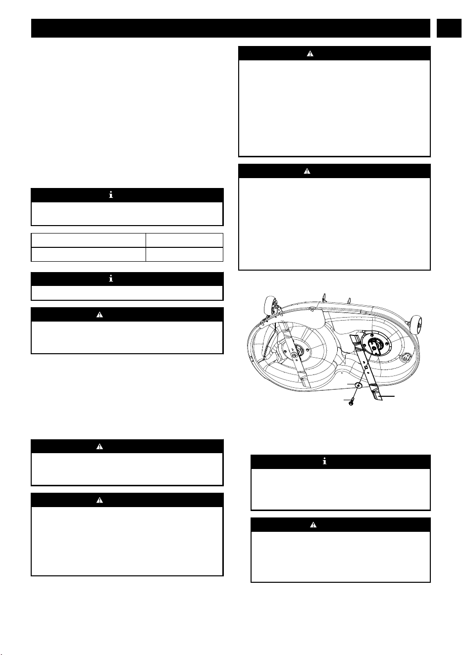
11.2.1 REPLACE THE BLADE
Blade
W
asher
Bolt
1. Stop the motor, remove the start key, and set the parking
brake.
2. Raise the height of the cutting deck to its highest position
to allow access to blades.
NOTE
If necessary, raise the mower by placing on a lift or
using a jack and jack stands, or remove the cutting deck
as described in the previous section to gain access to the
blades.
WARNING
If raising the mower to access the blades, make sure the
mower is properly secured and the parking brake is set
before proceeding. Failure to properly secure the mower
could cause it to fall, resulting in death or possible
serious personal injury.
3. Wedge a block of wood between the blade and mower
deck to prevent the blade from turning.
29
English
EN

4. Loosen the blade nut by turning it counterclockwise (as
viewed from bottom of mower) using a 16 mm wrench or
socket (not provided).
5. Remove the blade nut, spacer
, blade insulator, and blade.
6. Thread the blade nut on the shaft and finger tighten.
7. Torque the blade nut down clockwise using a torque
wrench (not provided) to ensure the bolt is properly
tightened. The recommended torque for the blade nut is
796~885 in. lbs.
WARNING
Ensure blade is properly seated and the blade nut is
tightened to the torque specifications above. Failure to
properly attach the blade could cause it to come loose
and result in possible serious personal injury.
8. Repeat with second blade, if needed.
NOTE
Make certain all parts are replaced in the exact order in
which they were removed.
11.3 REPLACE THE HEADLIGHT
LED Light
LED Light
Bolt
Bolt
1. Park the mower on a level surface and set the parking
brake.
2. Stop the motor and remove the start key.
3. Remove and set aside the hex head screw and flat washer
holding the mower floor panel in place.
4. Lift floor panel slightly to access the two hex head screws
and flat washers securing the headlight in place. Remove
screws and washers and set aside.
5. Unplug the old headlight and discard.
6. Plug in new headlight and reinstall washers and screws.
Tighten securely.
7. Lower floor panel and reinstall washer and screw to
secure.
11.4 LUBRICATION
Please add oil before operation.
Oil type SAE85W-90
Oil capacity 130 ml
Contact your Greenworks dealer to replace the lubrication.
NOTE
Replace the gearbox oil after you operate the machine for
50 hours for the first time, then replace the oil every 200
hours.
Oil ruler
Oil dra
in outlet
11.5 TORQUE VALUES
WARNING
Particular attention must be given to tightening the drive
wheel lug nuts and blade spindle bolts. Failure to correctly
torque these items may result in the loss of a wheel or blade,
which can cause serious damage or personal injury.
Torque values are given below:
Part Ft-lbs. Nm
Wheel (lug) nuts 89 120
Blade spindle bolt 66 90
Lug nuts only -It is recommended that these be checked after
the first 2 hours of operation, initially, every 100 hours and
following removal for repair or replacement.
For all other torques refer to the various mower parts manuals
for standard torque chart.
1
1.6 BATTERY PACK MAINTENANCE
Your Greenworks mower is powered by a battery pack which,
when maintained properly, will provide years of useful life.
For proper care, adhere to the following instructions:
•
Always charge batteries after each use.
• Whenever a battery pack is fully discharged and turned
off, it is best to recharge the battery as soon as possible.
Over-discharge of the battery pack means the battery life
will be shortened and the battery may become
permanently damaged. There is no need to fully charge; it
will be beneficial even if you only charge the battery pack
for 5-10 minutes. It is best to recharge it within 24 hours.
30
English
EN

• Check that battery cables are securely tightened to
batteries each time you service the battery.
•
Keep grass, dirt and debris from collecting near battery
terminals and in battery area.
• Charge batteries indoors in a well-ventilated and dry
location away from sparks or flames. Never expose
charger to rain, vapor or liquid.
• Charge only lithium batteries provided by Greenworks.
• Do not touch uninsulated portion of charger (terminal
pins) or of output connector.
• Do not use with defective cords and wires. Replace
defective cords and wires immediately.
• For long-term storage, please make sure the storage
temperature is -4°F - 113°F within one month, and 32°F -
95°F between two and 12 months.
• The working environment of the battery pack is 14°F -
113°F. Battery pack can be used a -5°F - 131°F for
discharge, and 32°F - 107°F for charge.
11.7 BATTERY COMPARTMENT
FILTER MAINTENANCE
Replace the battery compartment filter every 200 hours.
1
1.8 SERVICE
IMPORTANT
Wait for all movement to stop before adjusting, cleaning or
repairing. Repairs or maintenance requiring power should
be performed by trained maintenance personnel only. Read
and observe safety warnings in front of manual.
IMPORTANT
Repairs or maintenance requiring power should be
performed by trained maintenance personnel only.
• Park the mower on level ground. Make sure that you set
the park brake, and that the deck blade switch is in “OFF”
position. Raise deck, rotate key to “OFF” position,
remove key from switch and disconnect battery cables by
pulling inward on RED battery quick disconnect handle
in battery box compartment.
•
Any maintenance operation that requires the removal of
safety covers must be performed by a trained service
technician.
•
Before working on or under the deck, make certain
ignition switch is “OFF” and key is removed and deck
blade switch cannot be accidentally started and
disconnect battery cables by pulling inward on RED
battery quick disconnect handle in battery box
compartment.
• Use a stick or similar instrument to clean under the
mower, making sure that no part of the body -- especially
arms and hands -- is under mower.
• Keep your machine clean and remove any deposits of
trash and clippings.
• Keep battery compartment, deck and operator’s station
clean of accumulated trash, grass clippings, and other
debris.
•
Clean battery compartment, drive motor compartment,
mower deck, seat, etc., of all dirt and debris. T
o clean, use
only compressed air. DO NOT use water, solvents, hard
cleaners or abrasives.
• Always wear adequate eye protection when servicing the
batteries or when grinding mower blades and removing
accumulated debris. Never attempt to make any
adjustments or repairs to the mower’s drive system,
mower deck or any attachment while the traction drive
system is running. Repairs or maintenance requiring
power should be performed by trained maintenance
personnel only.
• Never work under the machine or attachment unless it is
safely supported with jack stands. Make certain machine
is secure when it is raised and placed on the jack stands.
• The jack stands should not allow the machine to move
when the traction drive system is running and the drive
wheels are rotating. Use only certified jack stands. Use
only appropriate jack stands, with a minimum weight
rating of 2000 pounds (907.2 kg) to block the unit up.
Use in pairs only. Follow the instructions supplied with
the vehicle stands.
• Do not touch hot parts of machine.
• Keep nuts and bolts tight, especially the blade attachment
bolts. Keep equipment in good working condition.
• Never tamper with safety devices. Check their proper
operation regularly.
• Turn the key to the “OFF” position before unclogging the
discharge chute.
• Never clear the discharge chute with the machine
running. Turn the key to the “OFF” position and be sure
the blades have stopped before cleaning. Use a stick to
clear a plugged discharge area. Never use your hand!
• Stop unit and allow blades to stop before unclogging
chute. Grass collection system components are subject to
wear, damage and deterioration, which could expose
moving parts or allow objects to be thrown. Frequently
check components and replace with manufacturer’s
recommended parts, when necessary.
• Exercise caution when working under the deck as the
mower blades are extremely sharp. Wear gloves and use
extra caution when servicing them.
• Use only genuine Greenworks Mower parts to ensure that
original standards are maintained.
• Always disconnect batteries when transporting unit. Keep
unit free of grass clippings, leaves and other debris.
• Check brake operation frequently. Adjust and service as
required.
• Maintain or replace safety and instruction labels, as
necessary.
• Have your ride-on lawn mower serviced by a qualified
repair person using only identical replacement parts. This
will ensure that the safety of the ride-on lawn mower is
maintained.
31
English
EN

• Recharge only with the charger specified by the
manufacturer. A char
ger that is suitable for one type of
battery pack may create a risk of fire when used with
another battery pack.
12 TRANSPORTATION
WARNING
Use extra care when loading or unloading the machine into a trailer. Press the low speed drive button and carefully move the
drive levers as needed to control the speed. Always back onto the trailer when loading. When loading or unloading the mower,
do not exceed the maximum recommended operation angle of 15°. Failure to follow these instructions can result in loss of
control and result in death, serious personal injury
, or property damage.
WARNING
Use care when loading or unloading the mower onto a trailer
. Ensure the cutting deck is raised to the highest position so that it
is not caught on the ramp. The wheels on the mower can go off the ramp or trailer
, causing the mower to pivot or tip over, and
result in a crush hazard that can cause death or serious personal injury.
1. Park the mower on a level surface.
2. Raise the cutting deck to the highest position.
3.
Position and secure ramp to the trailer according to manufacturer’s instructions.
NOTE
We recommend you use one full width loading ramp that is at least 1 ft. wider than the mower to minimize the risk of the
mower
’
s wheels going off the side of the ramp.
4. Slowly back the mower onto the ramp and into the trailer.
5. Lower mower deck completely
.
6. Set the parking brake.
7. Turn off mower and remove key.
8. Secure the mower as needed using straps or cables to prevent movement during transport.
W
ARNING
T
o avoid accidental starting or movement that could result in serious personal injury, always remove the start key and set
the parking brake when transporting the mower.
13 CLEANING AND STORAGE
13.1 CLEAN THE MOWER DECK
32
English
EN

• Set the parking brake into the parking slots. Refer to
section PARKING BRAKE SETTING in this manual.
•
Adjust the mower deck height to the lowest. Refer to
section "CUTTING-DECK HEIGHT ADJUSTMENT" in
this manual.
• Attach the supplied wash-port quick-coupler to garden
hose.
• Attach garden hose with quick-coupler to wash port on
the mower deck. The wash port is on the left side of the
mower deck.
• Turn on the water.
• Pull the PTO switch to start the mower cutting blades and
adjust the blade speed to the highest. Refer to section
"Blade-Speed Adjustment Button" in this manual.
• Flush water under the deck for approximately one minute.
• Disengage the mower blades by pushing the PTO switch
downward.
• Turn off the water and remove garden hose and quick-
coupler from wash port.
• Remove quick-coupler from garden hose and store for
future use.
• Turn off the mower completely. See section "STOPPING
THE ELECTRIC ZERO TURN MOWER".
13.2 STORE THE MACHINE
The following steps should be taken in order to prepare the
machine for storage.
• Clean the machine as described in the previous section.
•
Inspect the blade and replace it or sharpen it, if required
(refer to the Maintenance section).
• Do not store the machine next to corrosive materials, such
as fertilizer or rock salt.
• Keep the machine out of the reach of children.
• Do not cover the machine with a solid plastic sheet.
Plastic coverings trap moisture around the machine,
which causes rust and corrosion.
• Check thoroughly for any worn or damaged parts that
need replacing and order them from your dealer.
• Thoroughly lubricate machine, according to lubrication
instructions.
• Fully charge and service the batteries.
• Do not deflate tires.
• The machine should be stored in a well-ventilated, clean
and dry place.
13.3 PREPARE FOR USE AFTER
STOAGE
The following steps should be taken before using the mower
after it has been stored:
• Fully charge the batteries.
• Check tire pressure and inflate as needed.
• Briefly drive the mower and check all systems and
components to ensure they are functioning correctly.
33
English
EN

14 TROUBLESHOOTING
Problem Cause Solution
When you press
the accelerator
,
the machine
does not move.
1.
There is no battery pack in the battery compart-
ment, or the battery inserted is not Greenworks
designed.
2. The battery pack is out of power.
3. You engage the park brake.
4. There is no person sitting on the seat or the seat
switch is not connected.
5. The PTO switch is not in the original position
when the machine is powered on.
6. The discharge system of the drive battery com-
partment is in the sleep mode.
1. Make sure at least one Greenwoks designed bat-
tery pack is inserted in the battery compartment.
2. Check the battery capacity.
3. Make sure you fully disengage the park brake, so
the wheels can rotate freely.
4. Make sure the operator is sitting on the seat.
5. Return the switch to the initial position, and re-
start the machine. If the machine still fails to
work, contact the service center for help.
6. Turn the key to the OFF position, and restart the
machine 5 seconds later.
Sudden break-
down during
driving.
1. The battery is out of power.
2. The seat switch is disconnected on rugged or
bumpy roads.
3. The accelerator fails.
4. The vehicle controller fails.
1. Make sure at least one Greenwoks designed bat-
tery pack is inserted in the battery compartment.
Make sure the battery pack has power.
2. Restart the machine to check if the machine
works normally.
3. Contact a technical people for help.
The blade fails
to run when you
pull up the PTO
switch.
1. There is no Greenwoks designed battery pack in
the battery compartment.
2. The battery pack is out of power.
3. The seat switch is not connected.
4. The PTO switch is not pushed when the machine
is powered on.
5. The blade motor is blocked or other functional
protection.
1. Make sure at least one Greenwoks designed bat-
tery pack is inserted in the battery compartment.
Make sure the battery pack has power.
2. Check the battery capacity.
3. Make sure the operator is sitting on the seat.
4. Push down on the PTO switch, restart the ma-
chine.
5. Cut the grass in low blade speed when you power
on the machine, set the blade speed to high posi-
tion once the machine cuts normally. Check if the
connection between the blade and motor is with-
out grass or foreign objects to ensure the blade
rotates smoothly.
6. Turn the key to the OFF position, and restart the
machine 5 seconds later.
The blade stops
running during
the mowing
process.
1. The blade motor is overheated.
2. The deck is full of grass and garbage.
3. The blade motor is overloaded.
4. The battery pack termperature is too high.
5. The battery is undervoltage.
6. The blade is hit by a foreign object, causing the
blade to stop suddenly for protection.
1. Do not use the machine too much, power off the
machine for 5min. Raise the deck height or re-
duce the driving speed to protect the blade.
2. Clean the deck to ensure that the blade rotation is
normal.
3. Push down on the PTO switch; restart the ma-
chine. Raise the deck height or reduce the drive
speed to protect the blade.
4. The battery pack that controls the blade system
enters under-voltage protection state, and the bat-
tery should be charged immediately
5. Turn the key to the OFF position, and restart the
machine 5 seconds later.
34
English
EN

Problem Cause Solution
The machine
cuts the grass
unevenly.
1.
The blade is dull.
2. The blade is bent.
3. The deck is uneven.
1. Grind the blade according to the manual.
2. Replace the bent blade, replace the blade accord-
ing to the instructions in the manual, and wear
protective equipment.
3. Adjust the cutting deck according to the instruc-
tions in the manual to ensure the left and right
deck height are even.
The actual cut
height does not
match the cut
height you set.
1. The bolt of the deck is loose.
2. The deck is severely worn or damaged.
1. Adjust the cutting deck bolt, make sure the deck
is not loose. Please balance the deck level after
each adjustment.
2. Replace with a new cutting deck.
The machine
cuts the grass
abnormally.
1. The grass is too wet.
2. The grass amount you set is too much.
1. Please check the grass before working. If the
grass is too wet, please wait until the grass gets
drier.
2. If the grass is too intensive and high, raise the
deck height, and avoid cutting intensive grass.
The machine vi-
brates too much.
1. The blade is loose.
2. The blade is bent.
3. The deck is uneven.
4. The deck is loose.
5. The blade cuts too much grass more than the
amount you set.
1. Grind the blade according to the manual.
2. Replace the bent blade, replace the blade accord-
ing to the instructions in the manual, and wear
protective equipment.
3. Adjust the cutting deck according to the instruc-
tions in the manual to ensure the left and right
deck height are even.
4. Tighten the fixing bolts of the deck.
5. If the grass is too intensive and high, please raise
the cutting deck and try to avoid cutting intensive
grass.
There is grass or
debris on the
ground after
mowing.
1. The blade cuts too much grass more than the
amount you set.
2. The grass is too wet.
3. You drive too fast.
4. The blade speed is too low.
1. If the grass is too dense and high, please raise the
cutting deck. If the grass height exceeds 6 inch,
please cut the area repeatedly. Try to avoid cut-
ting intensive grass.
2. Please check the grass before working. If the
grass is too wet, please wait until the grass gets
drier.
3. Reduce the drive speed.
4. Turn the blade speed to high position.
The cutting en-
durance time is
short.
Heavy grass can short the running time of the lawn
mower.
Raise the cutting deck and reduce the blade speed to
extend the running time.
The machine is
off track.
The tire pressure of left and right rear wheels is dif-
ferent.
Regularly check the tire pressure of the rear tires ac-
cording to the manual.
The machine
fails to start af-
ter cleaning.
Improper cleaning, water enters the battery compart-
ment or the key switch fails.
1. When cleaning the machine, please clean it ac-
cording to the instructions.
2. If the vehicle is accidentally exposed to rain,
please put the vehicle in a dry place for 12 hours
or dry it before use.
3. Contact a service center for help.
The mower is
blocked.
The deck is full of weeds and garbage. Please clean the machine correctly according to the
instructions after each use.
35
English
EN
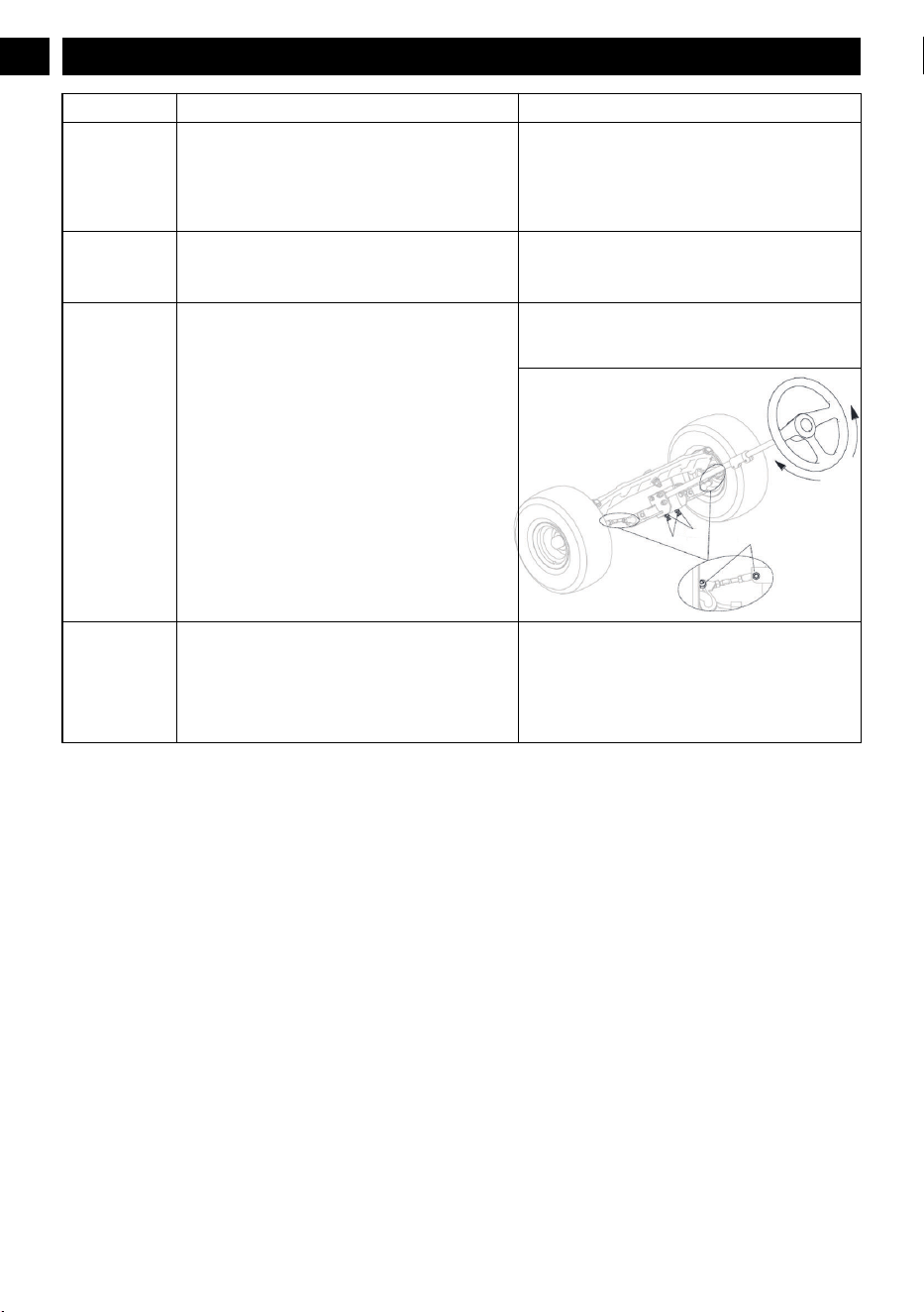
Problem Cause Solution
The steering
wheel does not
turn smoothly.
1.
Check whether there is rigidity stuck in the gear
and rack transmission.
2. Lack of lubrication oil, add lubrication oil.
3. The steering ball head and other parts are dam-
aged and deformed.
1. Clean up the debris and add lubrication oil.
2. Replace the damaged parts.
3. Adjust the gear space.
4. Contact a service center for help.
Drive axle fail-
ure.
1. Oil leakage.
2. The wheel hub heats up.
3. Abnormal sound.
Contact a service center for help.
Wheel steering
fails.
1. The transmission gear is worn for a long time.
2. The steering ball joint bolts are loose.
Check if the nut is loose. If the nut is tight, adjust the
nut until the wheel steers correctly. (See figure be-
low)
Nut M8
Nut M8
Nut M8
The machine
quickly moves
down the slope
even if you
press the brake
pedal.
1. Tire wear is too serious.
2. The brake pedal is damaged or worn severely
.
Contact a service center to replace the tire or check
the brake pedal.
36
English
EN

15 TECHNICAL DATA
Model No. CRT426 CRT428 CRT428
Voltage 60 V 80 V 82 V
Gross vehicle weight (lbs) 456 456 456
Length 74.4” 74.4” 74.4”
Height 52.5” 52.5” 52.5”
Width (with discharge) 43.8” 43.8” 43.8”
Deck width 42” 42” 42”
Forward speed (mph) 8 8 8
Reverse speed (mph) 3 3 3
Cutting height range 1.5-4.5" 1.5-4.5" 1.5-4.5"
Bucket capacity (lbs) 200 200 200
Towing capacity(lbs) 200 (include bucket capacity)
Battery model See website
Charger model See website
16 WARRANTY
Greenworks hereby warranties this product, to the original
purchaser with proof of purchase, for a period of four (4)
years or 200 hours of use (whichever comes first) against
defects in materials, parts or workmanship. Greenworks, at its
own discretion, will repair or replace any and all parts found
to be defective, through normal use, free of charge to the
customer
. This warranty is valid only for units which have
been used for personal use that have not been hired or rented
for industrial/commercial use, and that have been maintained
in accordance with the instructions in the owners’ manual
supplied with the product from new.
16.1 ITEMS NOT COVERED BY
WARRANTY
:
1. Any that have been transferred to a new owner. This
warranty only applies to the original purchaser from an
authorized Greenworks retailer or dealer. This warranty is
nontransferable.
2. Any part that has become inoperative due to misuse,
rental use, commercial use, abuse, neglect, accident,
improper maintenance, product modification,
unauthorized repair or alteration; or
3. If item has not been operated and/or maintained in
accordance with the owner’s manual; or
4. Normal wear.
5. Routine maintenance parts or service include, but are not
limited to: lubricants, mower seat wear, blade sharpening,
wheels, tiers, anti-scalp wheels, blades as well as any
optional accessories or attachments.
6. Normal deterioration of the exterior finish due to use or
exposure.
7. Damage or failure resulting from, but not solely:
immersion in water or other liquids, accidents, misuse,
neglect or lack of proper installation, and proper
maintenance and storage.
8. An item that has not been registered on an authorized
Greenworks website (see REGISTRA
TION info with QR
code or product page info for proper product registration).
16.2 HELPLINE:
Warranty service is available by calling our toll-free helpline,
at 1-888-909-6757 Greenworks Pro, 1-855-470-4267
Greenworks Commercial
.
16.3 TRANSPORTATION CHARGES:
Transportation charges for the movement of any power
equipment unit or attachment are the responsibility of the
purchaser. It is the purchaser
’s responsibility to pay
transportation chares for any part submitted for replacement
under this warranty unless such return is requested in writing
by Greenworks.
USA address: Canadian address:
Greenworks Tools Greenworks Tools Canada Inc.
P.O. Box 1238 P.O. Box 93095, Newmarket,
Ontario
Mooresville, NC 28115 L3Y 8K3
37
English
EN

17 GREENWORKS PRODUCT REGISTRATION:
NAME:
ADDRESS:
CITY: STATE: ZIP CODE: COUNTRY:
HOME PHONE: MOBILE PHONE:
PURCHASE DATE: PURCHASED FROM:
38
English
EN

18 SERIAL NUMBER(S)
Please list Serial Number(s) below along with Model Information:
DESCRIPTION MODEL # PART # SERIAL # DATE PUR-
CHASED
39
English
EN