INDUSTRIAL FAN HEATERS:
BTU/HR: 17,000, 31,000, 51,000: OUTPUT 5KW, 9KW, 15KW
MODEL NO: EH5001.V2, EH9001.V2, EH15001.V2
Thank you for purchasing a Sealey product. Manufactured to a high standard, this product will, if used according to these
instructions, and properly maintained, give you years of trouble free performance.
IMPORTANT: PLEASE READ THESE INSTRUCTIONS CAREFULLY. NOTE THE SAFE OPERATIONAL REQUIREMENTS, WARNINGS & CAUTIONS. USE
THE PRODUCT CORRECTLY AND WITH CARE FOR THE PURPOSE FOR WHICH IT IS INTENDED. FAILURE TO DO SO MAY CAUSE DAMAGE AND/OR
PERSONAL INJURY AND WILL INVALIDATE THE WARRANTY. KEEP THESE INSTRUCTIONS SAFE FOR FUTURE USE.
1. SAFETY
1.1. ELECTRICAL SAFETY
WARNING! It is the user’s responsibility to check the following:
9 Check all electrical equipment and appliances to ensure that they are safe before using. Inspect power supply leads, plugs and all
electrical connections for wear and damage. Sealey recommend that an RCD (Residual Current Device) is used with all electrical products.
Electrical safety information. It is important that the following information is read and understood:
9 Ensure that the insulation on all cables and on the appliance is safe before connecting it to the power supply.
9 Regularly inspect power supply cables and plugs for wear or damage and check all connections to ensure that they are secure.
Important: Ensure that the voltage rating on the appliance suits the power supply to be used and that the plug is tted with the correct fuse.
8 DO NOT pull or carry the appliance by the power cable.
8 DO NOT pull the plug from the socket by the cable.
8 DO NOT use worn or damaged cables, plugs or connectors. Ensure that any faulty item is repaired or is replaced immediately by a
qualied electrician.
If the cable or plug is damaged during use, switch o the electricity supply and remove from use.
Ensurethatrepairsarecarriedoutbyaqualiedelectrician.
If an extension reel is used it should be as short as possible and fully unwound before connection. A reel with an RCD fitted is preferred
since any appliance plugged into it will be protected. The cable core section is important and should be at least 1.5mm², but to be
absolutely sure that the capacity of the reel is suitable for this product and for others which may be used in the other output sockets, we
recommend the use of 2.5mm² section cable.
1.2. GENERAL SAFETY
WARNING! The appliance shall be disconnected from its power source during service and when replacing parts and, if the removal
of the plug is foreseen, it shall be clearly indicated that the removal of the plug has to be such that an operator can check from any
of the points to which they has access that the plug remains removed.
WARNING! DO NOT use this heater in small rooms when they are occupied by persons not capable of leaving the room on their own,
unless constant supervision is provided.
9 Servicing or maintenance must only be carried out by an authorised service agent.
9 Check that the heater is in sound condition and good working order. Take immediate action to repair or replace damaged parts.
9 Use recommended parts only. Unapproved parts may be dangerous and will invalidate the warranty.
8 DO NOT attempt to repair a damaged heater, contact an authorised service agent.
WARNING! In order to avoid overheating, DO NOT cover the heater.
1.3. POSITIONING OF HEATER
WARNING! To reduce the risk of fire, keep textiles, curtains, or any other flammable material a minimum distance of 1m from the air outlet.
WARNING! DO NOT use the heater near ammable material, liquids, solids, gases or compressed gas cylinders etc.
9 Use this heater on a horizontal and stable surface or x it to a wall as applicable.
8 DO NOT use this heater in the immediate surroundings of a bath, a shower or a swimming pool.
8 DO NOT place the heater up against any surface such as a wall, door or furniture etc.
8 DO NOT place the heater immediately below any electrical outlet.
8 DO NOT place the heater on a raised surface or anywhere where it could topple over.
8 DO NOT get the heater wet or use in areas of high condensation.
Refer to
instructions
Indoor Use
Only
EH5001
EH9001
EH15001
THIS PRODUCT IS ONLY SUITABLE FOR WELL INSULATED AREAS OR OCCASIONAL USE.
Do Not
Cover
EH15001.V2, EH9001.V2, EH5001.V2 Issue 3 (1,F) 07/11/23
Original Language Version
© Jack Sealey Limited
8 DO NOT allow the power lead to touch hot surfaces.
8 DO NOT connect the heater to a timer device or other equipment than can automatically switch the heater on or off.
8 DO NOT operate the heater when you are tired or under the influence of alcohol, drugs or intoxicating medication.
8 DO NOT stand on the heater.
8 DO NOT use the heater with wet hands or when there is water on the power cord.
8 DO NOT use the heater for anything other than its intended purpose. It is designed to provide heat in enclosed areas such as
workshops and other industrial areas. It is not suitable for drying clothes or laundry.
9 Position the heater at least a minimum of 1m at the front, rear and sides from any walls or objects.
9 If an extension cable is required it must be of the same cross section as the heater cable. It must be as short as possible and fully unwound.
9 Ensure that the heater is correctly turned o when not in use and store in a safe, dry, childproof location.
1.4. OPERATIONAL PRECAUTIONS
9 The heater must only be used by people who have read these instructions and have been trained in its use.
8 DO NOT obstruct the air inlet and outlet sections of the heater.
WARNING! In order to avoid overheating, DO NOT cover the heater.
8 DO NOT use the heater without the grille fitted.
8 DO NOT use if the heater has been dropped.
8 DO NOT use if there are visible signs of damage to the heater.
8 DO NOT touch the heater casing or grille when rst switched o, as these will be very hot and will take time to cool.
NOTE: Children of less than 3 years should be kept away unless supervised continuously.
Children aged from 3 years and less than 8 years shall only switch on/off the appliance provided that it has been placed or installed in its
intended normal operating position and they have been given supervision or instruction concerning use of the appliance in a safe way and
understand the hazards involved. Children aged from 3 years and less than 8 years shall not plug in, regulate and clean the appliance or
perform user maintenance.
CAUTION: Some parts of this product can become very hot and cause burns. Particular attention has to be given where children and
vulnerable people are present.
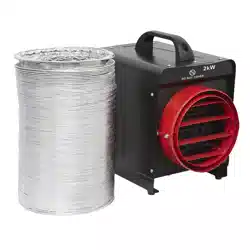
2. INTRODUCTION
Electric fan heaters for industrial applications. Model No’s EH5001, EH9001 and EH30001 feature two heat settings and fan only
option. Model No. EH15001 features three heat settings and adjustable thermostat control with fan only option. Auto cooling system
to prevent unit from overheating during use. A totally dry heat with no condensation, no gas, no fumes and no smell. Ideal for
workshops and garages. Model No’s EH5001 and EH9001 supplied with 3-phase power cable and 16A plug. Model No’s EH15001
and EH30001 supplied with 3-phase chassis mounted 5-pin connector (extension cable required).
3. SPECIFICATION
MODEL NO. EH5001.V2 EH9001.V2 EH15001.V2
Heated Area: 48m
3
80m
3
120m
3
Output: Btu/hr 17,000 31,000 51,000
Plug Type: Red - 16A-4P+E Red - 16A-4P+E Red - 32A-4P+E
Power Supply Cable Length: 1.35m 1.35m N/A
Power: 2500/5000W 4500/9000W 7500/15000
Supply: 415/3ph-16A 415/3PH - 16A 415/3ph-32A
IMPORTANT!
This unit is designed to raise the ambient temperature of an entire room, the temperature of the air coming out of the front of the
heater will be warmer than the general temperature of the room, but there may not be a signicant increase owing to the large
volume of air passing over the element. For the same reason, the element is hot during operation, but does not glow. The room
temperature depends on room size, insulation and ambient temperature, which will increase as the room warms.
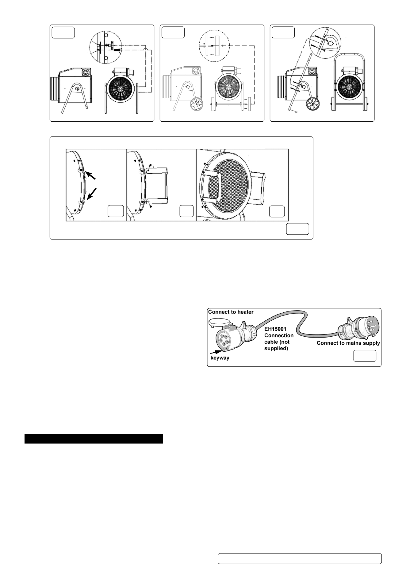
3.1. EH15001.V2ONLY-ASSEMBLYOFTHEWHEELS.(g.2)
3.1.1. Take the axle rod and insert it through the holes in the ‘V’ frames so that the threaded rod ends protrude equally either side. Retain
the axle rod in this position by inserting a split pin through the holes situated just on the inside of each leg frame.
3.1.2. Slide a plain washer over each end of the axle rod, followed by a wheel then followed by another plain washer.
3.1.3. Screw a nyloc nut onto each end of the axle by hand until it begins to bite. Hold one nut steady with a 19mm spanner and
progressively finger-tighten each nut until it bottoms out on the thread. Once the heater body is fitted between the legs tighten the nuts to
fix the wheels in position.
3.2. EH15001.V2ONLY-ASSEMBLYOFTHELEGSTOBODY.(g.1)
3.2.1. Screw thumb-wheel, lock washer and plain washer nger-tight into insert in body of heater via central hole in the gusset at the top of
the legs.
3.2.2. Screw pivot bolt into insert tted to body via the slot in the gusset. Tighten all xings once assembled.
3.2.3. Note that the axle hole at the shorter end of the ‘V’ frames should be orientated towards the back of the heater.
3.3. EH15001.V2 ONLY - ASSEMBLY OF THE HANDLE.(g.3)
3.3.1. Slide a plain washer over each of the four M5 x 50mm bolts supplied.
3.3.2. Lay the ‘U’ shaped handle frame onto the front face of the leg frames and align the two holes at each end of the handle frame with the two
holes in each leg frame. Insert two bolts at each joint as indicated in fig.3.
3.3.3. Whilst continuing to support the handle frame slide a plain washer followed by a split washer onto the end of each protruding bolt
and retain them with a nut. Tighten all four nuts with an 8mm spanner.
EH15001.V2, EH9001.V2, EH5001.V2 Issue 3 (1,F) 07/11/23
Original Language Version
© Jack Sealey Limited
g.1
g.2 g.3
3.4. ASSEMBLYOFTHEFRONTSUPPORTS(EH5001.V2,EH9001.V2ONLY)(g.4)
g.4
A B
C
3.4.1. Remove screws (M4 x 12mm) from both sides of heater throat (g.4A).
3.4.2. Attach supports using screws from 4.4.1 above (g.4B).
3.4.3. Note orientation of supports (g.4C).
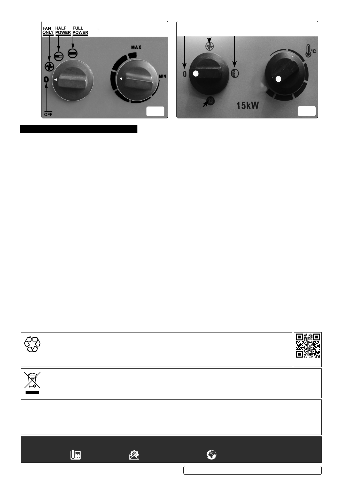
3.5. CONNECTING TO MAINS SUPPLY
3.5.1. The heater (EH15001) is supplied with a protected 5 pin connector mounted on the side of the control housing. In order to connect to the
mains it will be necessary to have the extension cable shown in fig.5 made up by a qualified electrician. (This connector is not supplied
with the machine.) The cable should be no shorter than 1.8m and no longer than 3.0m.
3.5.2. Before connecting the heaters to the mains ensure that the
selector switch is set to OFF and the thermostat is set at
minimum.
3.5.3. Hold open the protective cover on the socket connector on the
extension lead as shown above and present it to the heater
connector in the correct orientation so that the spigot on the
heater connector passes into the keyway on the socket
connector. Push the socket connector fully home.
3.5.4. Connect the other end of the extension cable to the mains
supply.
3.6. THERMOSTATIC PROTECTION.
3.6.1. The heaters have a thermal cut out to prevent the unit from overheating for any reason, especially if the air input is restricted. If the
temperature of the front grille reaches 45ºC a thermal cutout will operate, turning off the heating elements. When the fan has cooled the
unit to 40ºC, normal thermostatic operation will resume.
3.6.2. AUTO COOLING. It is recommended that the thermostat should be set to the minimum to cool the unit prior to switching o. If the unit
is switched o when operating at full temperature, and the front grille has reached 45ºC, the time delay thermostat will keep the fan
running to cool down the unit. When the front grille has cooled to 40ºC the fan will stop running.
NOTE: Auto cooling will only function if the unit is plugged into the mains and the mains is ON.
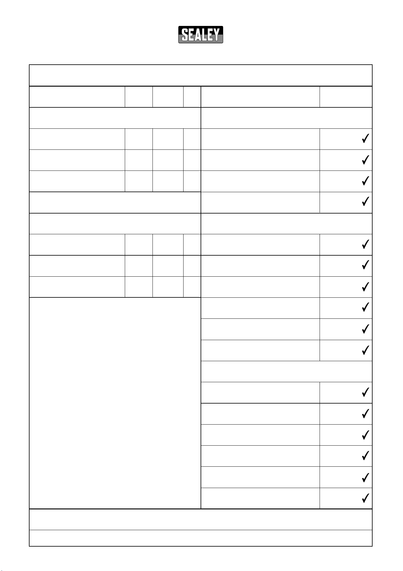
4. OPERATION
4.1. Position heater in an upright position on a firm and level surface and at a safe distance from any obstructions, flammable substances etc.
Keep to a minimum of 1m clearance at the front, rear and sides.
4.2. Connect the heater to a suitable mains supply.
4.3. Referring to either fig.6 or fig.7, set the thermostat dial to the maximum setting (fully clockwise).
4.4. The heater will switch on when the power setting selector is set to one of the power settings.
NOTE: It will take up to three minutes for the heater to reach optimum temperature.
4.5. Once the room reaches the required temperature, turn the thermostat dial slowly counter-clockwise until the thermostat clicks, leave the
dial in this position and the room temperature will be maintained at this setting. The heater will continue to operate until the power
switch is turned to the OFF position.
4.6. For fan only operation, turn the power/fan selector to the fan only setting and set the thermostat to its minimum setting.
4.7. When not in use, disconnect the heater from the mains supply. Store it in a safe, dry, childproof location.
g.5
M4 x 12mm
Screws
EH15001.V2, EH9001.V2, EH5001.V2 Issue 3 (1,F) 07/11/23
Original Language Version
© Jack Sealey Limited
g.7
FAN
ONLY
OFF
HALF
POWER
FULL
POWER
MIN
MAX
EH15001.V2
g.6
EH5001.V2 EH9001.V2
5. MAINTENANCE
WARNING! Before attempting any maintenance, ensure that the unit is unplugged from the mains power supply and that it has cooled down.
5.1. Clean the heater with a soft dry cloth only. DO NOT use abrasives or solvents.
5.2. Periodically check the heater grille to ensure that it is not blocked. No other maintenance is necessary. If a problem with the heater
is experienced, or if the power lead or plug is damaged, contact your local authorised service agent for repair. DO NOT dismantle or
tamper with the heater, as this may be dangerous and will invalidate the warranty.
NOTE: It may take up to three minutes for the heater elements to reach optimum temperature. This is normal and not a fault.
WEEE REGULATIONS
Dispose of this product at the end of its working life in compliance with the EU Directive on Waste Electrical and Electronic Equipment
(WEEE). When the product is no longer required, it must be disposed of in an environmentally protective way. Contact your local solid
waste authority for recycling information.
EH15001.V2, EH9001.V2, EH5001.V2 Issue 3 (1,F) 07/11/23
Original Language Version
© Jack Sealey Limited
Sealey Group, Kempson Way, Suffolk Business Park, Bury St Edmunds, Suffolk. IP32 7AR
01284 757500 sales@sealey.co.uk www.sealey.co.uk
Note: It is our policy to continually improve products and as such we reserve the right to alter data, specifications and component parts without prior
notice. Please note that other versions of this product are available. If you require documentation for alternative versions, please email or call
our technical team on technical@sealey.co.uk or 01284 757505.
Important: No Liability is accepted for incorrect use of this product.
Warranty: Guarantee is 12 months from purchase date, proof of which is required for any claim.
ENVIRONMENT PROTECTION
Recycle unwanted materials instead of disposing of them as waste. All tools, accessories and packaging should be
sorted, taken to a recycling centre and disposed of in a manner which is compatible with the environment. When
the product becomes completely unserviceable and requires disposal, drain any uids (if applicable) into approved
containers and dispose of the product and uids according to local regulations.
REGISTER YOUR
PURCHASE HERE
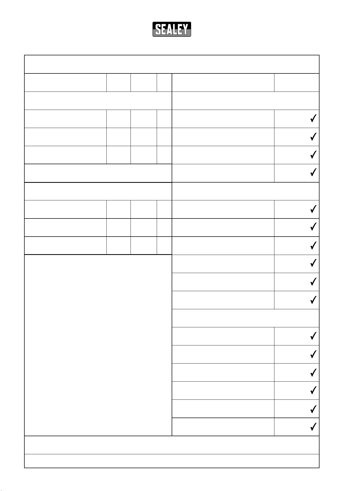
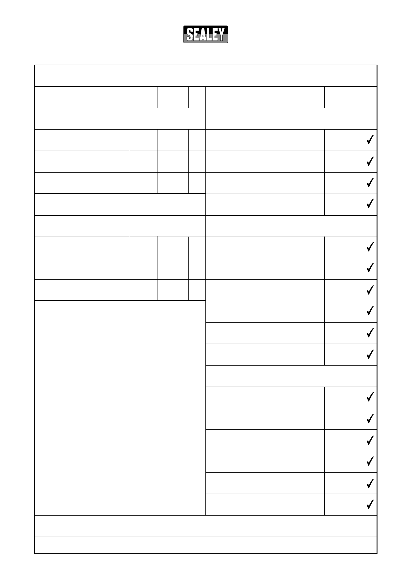
Information requirements for electric local space heaters
* Enter gure or NA
Model identier(s):
Item Symbol Value Unit Item Unit
Heat output
Type of heat input, for electric storage local space heaters
only (select one)
Nominal heat output
P
nom
kW
Manual heat charge control, with
Yes No
integrated thermostat
Minimum heat output (indicative)* P
min
kW
Manual heat charge control with room
Yes No
and/or outdoor temperature feedback
Maximum continuous heat output
P
max,c
kW
Electronic heat charge control with room
Yes No
and/or outdoor temperature feedback
Fan assisted heat output Yes No
Type of heat output/room temperature control (select one)
Single stage heat output and no room
Yes No
temperature control
Two or more manual stages, no room
Yes No
temperature control
With mechanic thermostat room
Yes No
temperature control
With electronic room temperature control Yes No
Electronic room temperature control plus
Yes No
day timer
Electronic room temperature control plus
Yes No
week timer
Other control options (multiple selections possible)
Room temperature control, with presence
Yes No
detection
Room temperature control, with open
Yes No
window detection
With distance control option Yes No
With adaptive start control Yes No
With working time limitation Yes No
With black bulb sensor Yes No
Contact details: Sealey Group, Kempson Way, Suolk Business Park, Bury St Edmunds, Suolk, IP32 7AR. www.sealey.co.uk
ERP Table 2
Auxiliary electricity consumption
At nominal heat output el
max
kW
At minimum heat output el
min
kW
In standby mode el
SB
kW
EH5001 v2 Industrial Fan Heater 5kW 415V 3ph
NA
NA
NA
5.0
2.5
5.0
v1
Information requirements for electric local space heaters
* Enter gure or NA
Model identier(s):
Item Symbol Value Unit Item Unit
Heat output
Type of heat input, for electric storage local space heaters
only (select one)
Nominal heat output
P
nom
kW
Manual heat charge control, with
Yes No
integrated thermostat
Minimum heat output (indicative)* P
min
kW
Manual heat charge control with room
Yes No
and/or outdoor temperature feedback
Maximum continuous heat output
P
max,c
kW
Electronic heat charge control with room
Yes No
and/or outdoor temperature feedback
Fan assisted heat output Yes No
Type of heat output/room temperature control (select one)
Single stage heat output and no room
Yes No
temperature control
Two or more manual stages, no room
Yes No
temperature control
With mechanic thermostat room
Yes No
temperature control
With electronic room temperature control Yes No
Electronic room temperature control plus
Yes No
day timer
Electronic room temperature control plus
Yes No
week timer
Other control options (multiple selections possible)
Room temperature control, with presence
Yes No
detection
Room temperature control, with open
Yes No
window detection
With distance control option Yes No
With adaptive start control Yes No
With working time limitation Yes No
With black bulb sensor Yes No
Contact details: Sealey Group, Kempson Way, Suolk Business Park, Bury St Edmunds, Suolk, IP32 7AR. www.sealey.co.uk
ERP Table 2
Auxiliary electricity consumption
At nominal heat output el
max
kW
At minimum heat output el
min
kW
In standby mode el
SB
kW
EH9001 v2 Industrial Fan Heater 9kW 415V 3ph
NA
NA
NA
9.0
4.5
9.0
v1
Information requirements for electric local space heaters
* Enter gure or NA
Model identier(s):
Item Symbol Value Unit Item Unit
Heat output
Type of heat input, for electric storage local space heaters
only (select one)
Nominal heat output
P
nom
kW
Manual heat charge control, with
Yes No
integrated thermostat
Minimum heat output (indicative)* P
min
kW
Manual heat charge control with room
Yes No
and/or outdoor temperature feedback
Maximum continuous heat output
P
max,c
kW
Electronic heat charge control with room
Yes No
and/or outdoor temperature feedback
Fan assisted heat output Yes No
Type of heat output/room temperature control (select one)
Single stage heat output and no room
Yes No
temperature control
Two or more manual stages, no room
Yes No
temperature control
With mechanic thermostat room
Yes No
temperature control
With electronic room temperature control Yes No
Electronic room temperature control plus
Yes No
day timer
Electronic room temperature control plus
Yes No
week timer
Other control options (multiple selections possible)
Room temperature control, with presence
Yes No
detection
Room temperature control, with open
Yes No
window detection
With distance control option Yes No
With adaptive start control Yes No
With working time limitation Yes No
With black bulb sensor Yes No
Contact details: Sealey Group, Kempson Way, Suolk Business Park, Bury St Edmunds, Suolk, IP32 7AR. www.sealey.co.uk
ERP Table 2
Auxiliary electricity consumption
At nominal heat output el
max
kW
At minimum heat output el
min
kW
In standby mode el
SB
kW
EH15001 v2 Industrial Fan Heater 15kW 415V 3ph
NA
NA
NA
15.0
5.0
15.0
v1