
Installation
GUIDE
7 SERIES
Multi-Unit Refrigeration Connector Kit
CKVBI / CKVBIW / CKVBIG
2
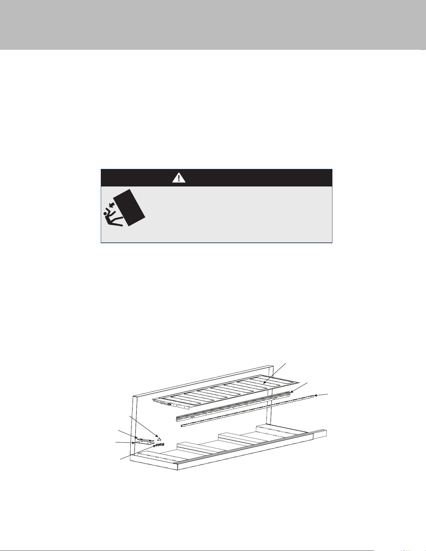
Parts included Tools Needed
•Heater (1)
•Center Trim Brackets (2)
•Center Trim (1)
•Top Connecting Plate (1)
•Rear Connecting Plate (1)
•1/4”-20 x 3/4” Connecting Plate Fasteners (6)
•#8-18 x 1/2” Heater Fasteners (3)
• Drill (Not to be used on the leveling feet or
connecting plates)
•Drill Bits - 3” Phillips (PH2), Torx (T15 & T20)
•1/4” & 5/16” Hex Drive
•Rubber Mallet
•3/8” Wrench
•1/8” Allen Wrench
Parts Included ____________________________________________________________________________________________2
Tools Needed ____________________________________________________________________________________________2
Install Con gurations & Clearances ___________________________________________________________________________3
Cutout dimensions ________________________________________________________________________________________4
Speci cations ____________________________________________________________________________________________5
Anti-tip location __________________________________________________________________________________________6
Preparing Units for Installation ______________________________________________________________________________7
Installation ______________________________________________________________________________________________9
Table of Contents
NOTE: These instructions include information on how to install multiple 7 Series refrigeration units. For information on
dimensions, speci cations, and installation of single units, please refer to the installation guide included with the appliances.
WARNING
TIP OVER HAZARD
Appliance is top heavy and tips easily when not completely
installed. Keep doors closed until appliance is completely installed
and secured per installation instructions.
Use two or more people to move and install appliance. Failure to do
so can result in death or serious injury.
8-18 x 1/2” Heater Fasteners (Item 7)
Rear Connecting Plate (Item 5)
Top Connecting Plate (Item 4)
1/4”-20 x 3/4” Connecting Plate
Fasteners (Item 6)
Heater (Item 1)
Center Trim Brackets (Item 2)
Center Trim (Item 3)
3
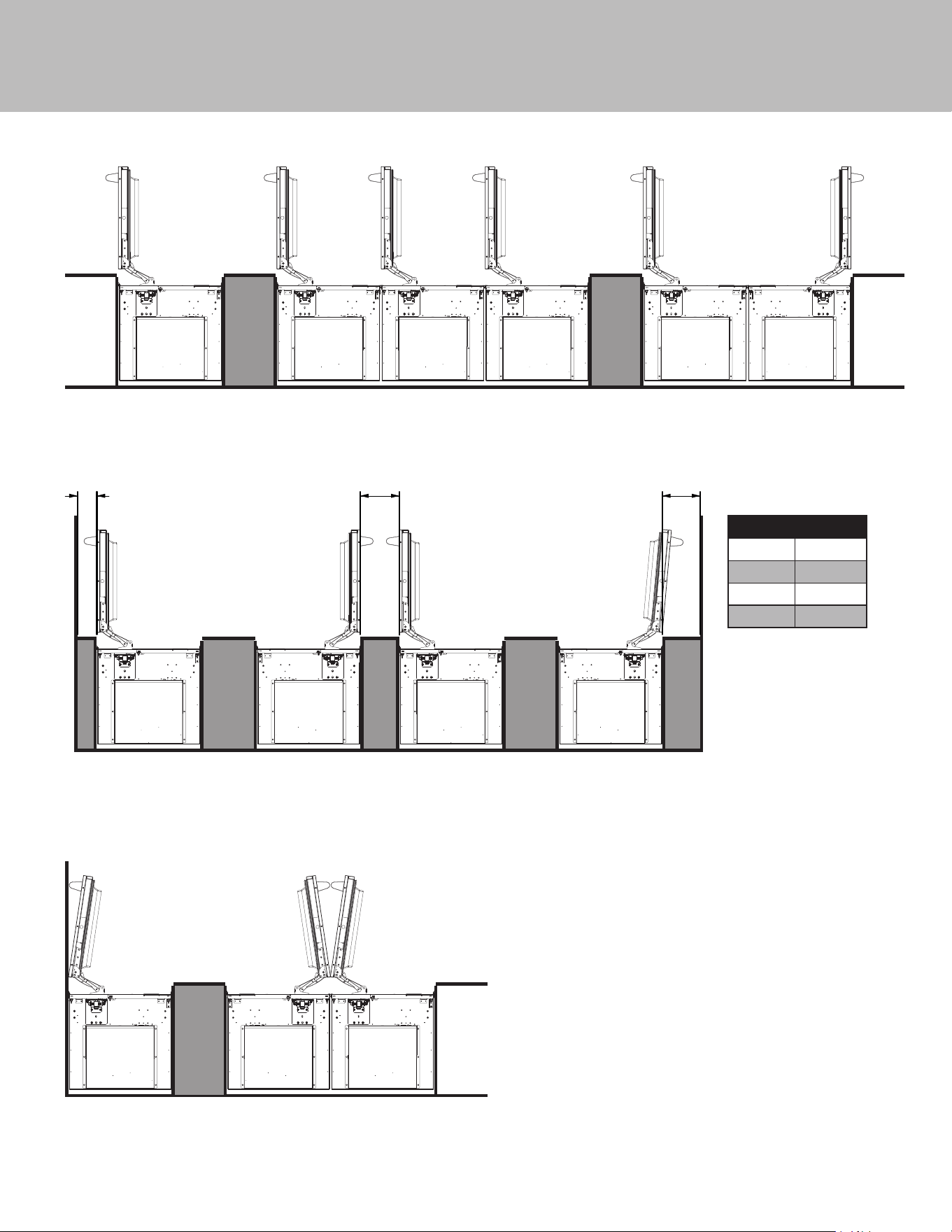
Install Con gurations & Clearances
Recomended Congurations
Recomended Clearances
Incorrect Congurations
A9"4.5"
Single Unit
Install
Stacked Unit Install
(All LH or RH Units)
Unit in a Corner Door stop set at 90°
(Min. 4.5” from cutout to wall)
Unit in a Corner
Door stop set to greater than 90°
(Refer to Chart for Cutout to Wall Clearance)
Units set Hinge to Hinge
with the hinges set to 90°
(Min. 9” from cutout to cutout)
Side by Side Unit Install
(Opposing LH & RH Units)
Zero Clearance
in Corner
Zero Clearance
Hinge to Hinge Install
Dim. A
Unit Size
18 9.75”
11.5”
13”
18.75”
24
30
36
Recommended Clearances
Recommended Con gurations
Incorrect Con gurations
4
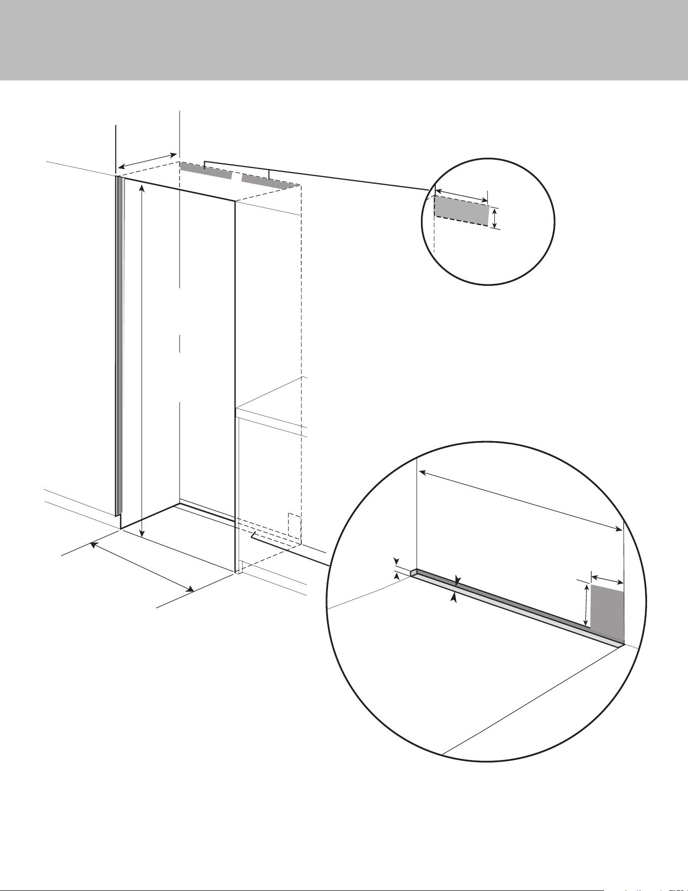
Cutout Dimensions
Can be located on either side
84”
(213.4 cm) min.
opening height
85-3/16”
(216.3cm) max.
opening height
Refer to Specication
chart for
specic Models
25”
(63.5 cm)
Electric Outlet Location
Water Line Entry Area
There must be a separate 15 amp
outlet for each unit installed
3”
(7.6 cm)
6”
(15.2 cm)
5/8”
(1.6 cm)
Cutout
Width
1/2”
(1.3 cm)
15-1/2”
(39.4 cm)
4-1/4”
(10.8 cm)
+
leveling
dimension
*Note: For all
models, 3” back
from the front
of the cabinet
on both sides
needs to be
nished like the
outside of the
cabinets
5
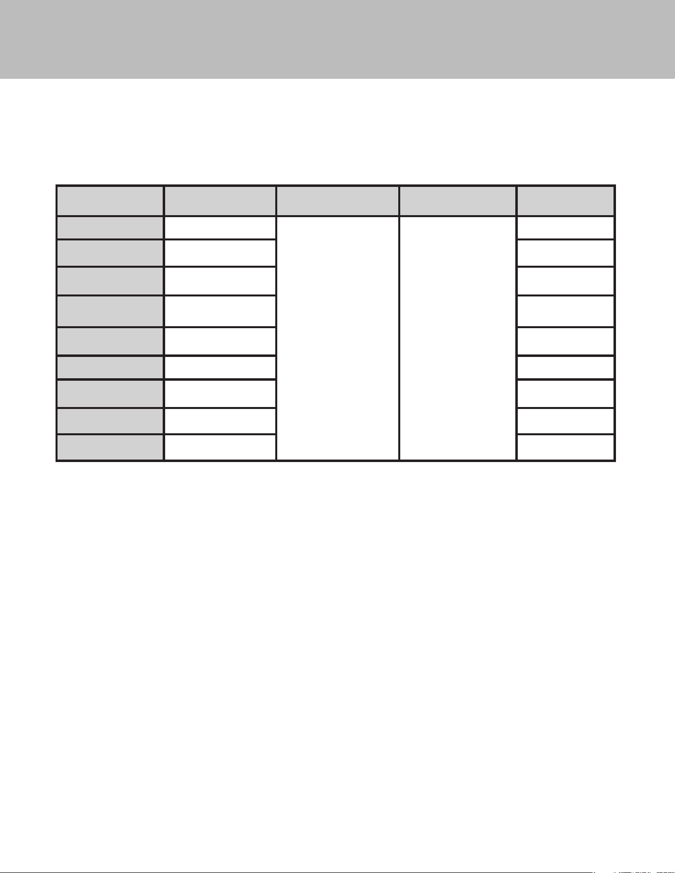
Speci cations
Refer to Installation Guides included with unit for individual dimensions.
Below is a common install chart for reference.
Size Combination Cabinet Cutout Width
Cabinet Cutout Height
(same for all)
Cabinet Cutout Depth
(same for all)
Optional
Kickplate
18” W / 24”W Models 42” (106.7 cm)
84” (213.4 cm) min
85-3/16” (216.3 cm) max
25”
(63.5 cm)
TKK742SS
18” W / 30”W Models 48” (121.9 cm) TKK748SS
18” W / 36”W Models 54” (137.2 cm) TKK754SS
24” W / 24”W Models 48” (121.9 cm) TKK748SS
24” W / 30”W Models 54” (137.2 cm)” TKK754SS
24” W / 36”W Models 60” (152.4 cm) TKK760SS
30” W / 30”W Models 60” (152.4 cm) TKK760SS
30” W / 36”W Models 66” (167.6 cm) TKK766SS
36” W / 36”W Models 72” (182.9 cm) TKK772SS
For muti-unit installation, add the width of the units together for cabinet cutout width.
For example: 18” + 24” + 24” = 66” W.
6
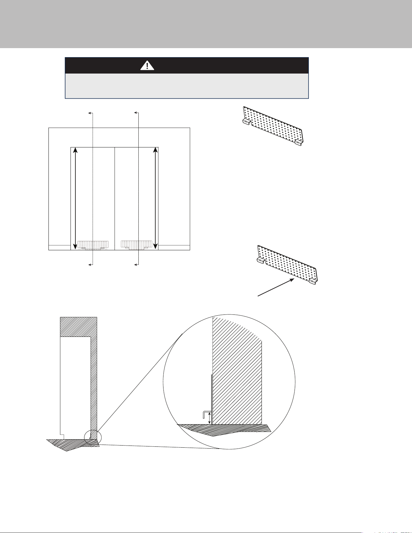
Anti-tip Location
C
C
Cabinet
Rear
Floor
A
Cabinet
Opening
Cabinet
Opening
C
C
Dimension A = Cabinet opening minus the refrigerator height + 1-1/4" (3.2 cm)
Ex. - Cabinet opening height - 85”
Minimum refrigerator height (sitting on rollers) - 83 15/16”
A = 85” - 83-15/16” +1-1/4” = 2-5/16”
Anti-tip Bracket
The anti-tip bracket has several holes set up on a grid in order to
better locate a wall stud. At least 4 places must be used. Anti-tip
Bracket must be centered in cutout - side to side.
NOTE: Number and type of fasteners must be suitable in order to
prevent tipping. For example: use wood screws into wall studs or
masonry anchors if attaching to stone, brick or concrete.
If a wall stud can not be found or when installing
the 18” model, use the lower section of the bracket
and mount to the base board
WARNING
Proper placement of anti tip bracket is an important function of the installation
process. The installer shall check and make sure that the unit is getting engaged with
the bracket when they try to tilt the unit from top similar to the unit tipping condition.
If the depth of the cabinet is more than the speci ed dimension of
25" (63.5 cm), anti tip bracket shall be installed with spacer (Shims)
to maintain the bracket location to be 25" (63.5 cm).
7
Preparing Units for Installation
Before removing units from pallet, remove / replace the side trim from each unit if needed, install center trim brackets and
connection heater. Make sure units are unplugged and powered o .
Look closely at the trim already installed on the unit.
If the trim resembles that in Trim A, it will need to be
removed and replaced with Trim B. If the trim already
resembles Trim B, leave as is.
REMOVE TRIM A
INSTALL TRIM B
A
A
8
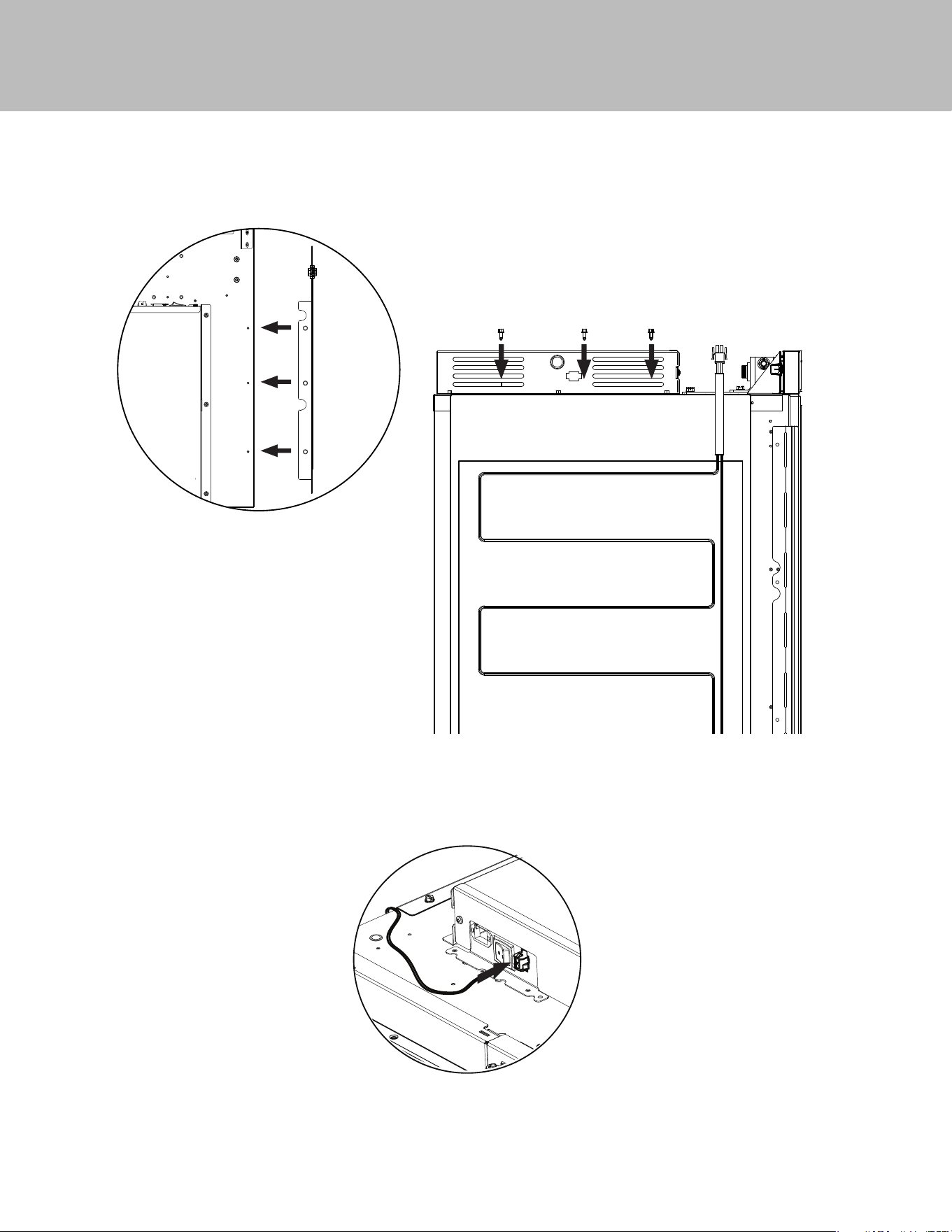
Preparing Units for Installation
1. Fasten heater (Item #1) to the three mounting holes on top of the right hand unit using the #8-18 x 1/2” fasteners (Item #7)
provided.
2. Plug heater terminal into right hand unit using the plug located next to the unit on/o switch.
9
Installation
WARNING
TIP OVER HAZARD
Appliance is top heavy and tips easily when not completely
installed. Keep doors closed until appliance is completely installed
and secured per installation instructions.
Use two or more people to move and install appliance. Failure to do
so can result in death or serious injury.
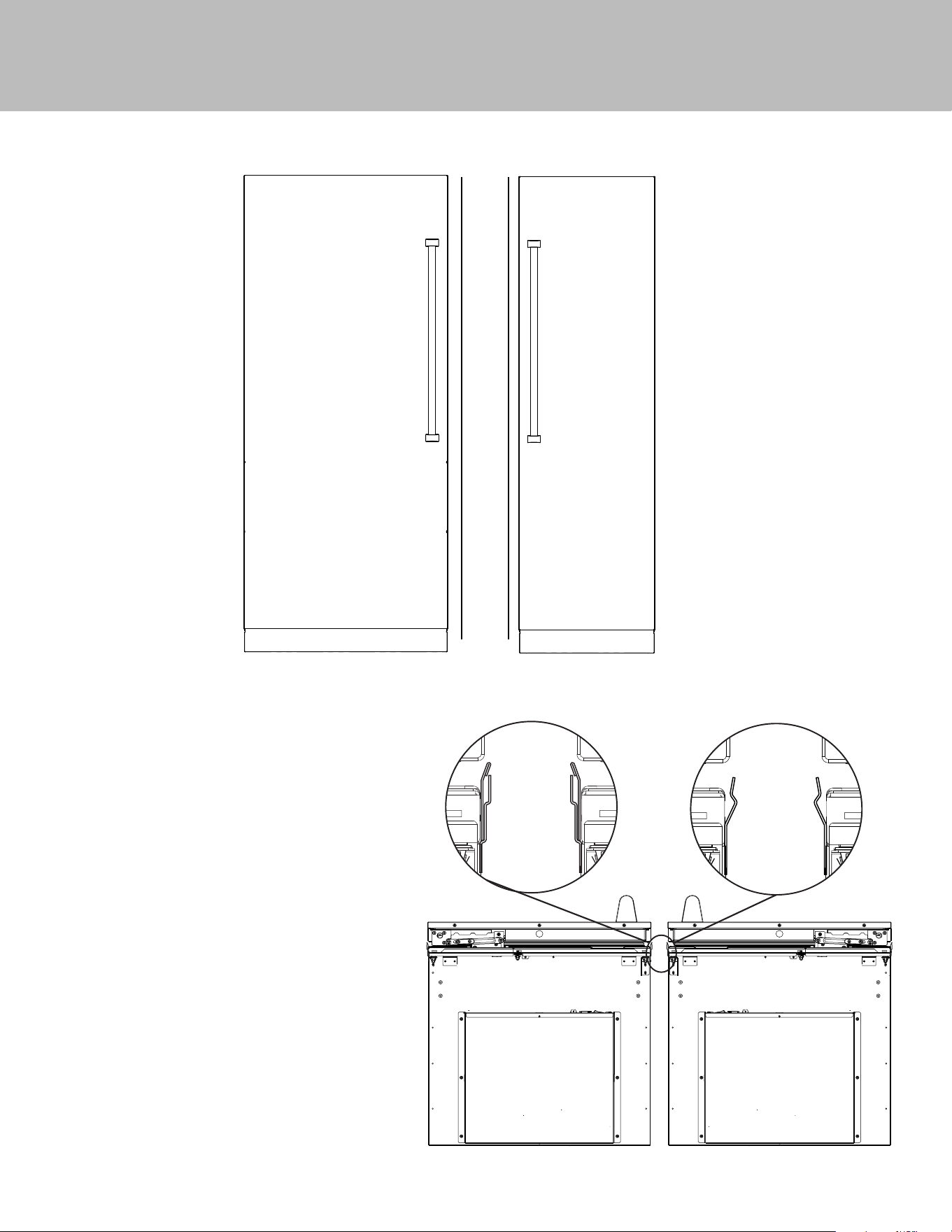
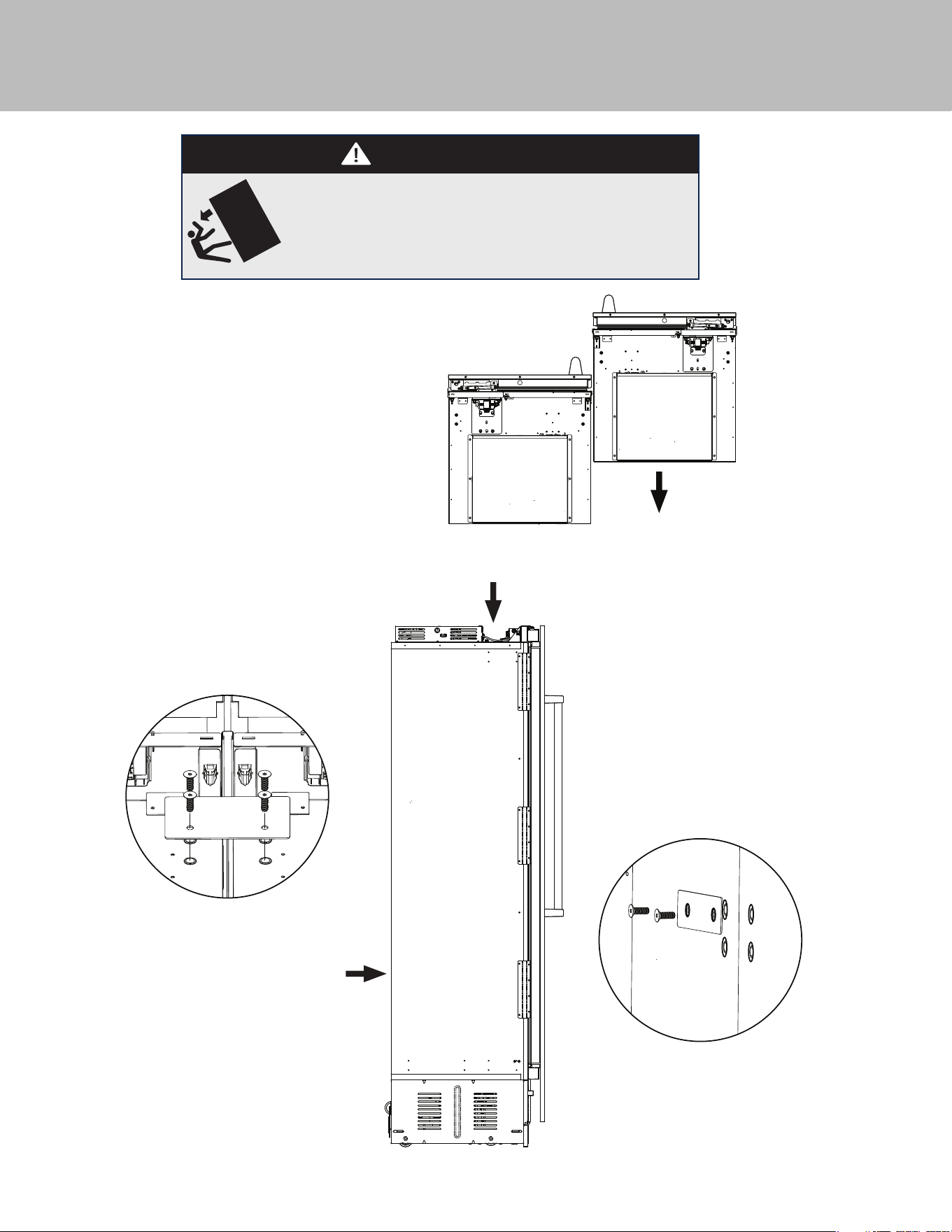
3. Remove units from pallets and position together
outside of the cabinet so that top connecting plate
(Item #4) can be installed. If installing on uneven
surfaces, use unit leveling feet to adjust units so
they are at the same height.
5. Fasten rear connecting plate (Item #5) to the
threaded mounting holes provided on the
rear of the unit using the 1/4”-20 x 3/4” (Item
#6) fasteners. DO NOT install using a drill.
Use manual allen wrench. (See Illustration B).
Loosely attach the bracket allowing it to pivot.
Tightening the screws will result in the bracket
bending and causing misalignment of the rear
of the units.
4. Install top connecting plate to the threaded
mounting holes provided on the top of the
cabinet using the 1/4”-20 x 3/4” (Item #6)
fasteners. DO NOT install using a drill. Use
manual allen wrench. (See Illustration A)
A.
B.
*
A.
B.
Note: *If one or both units have (4)
screw holes, attach using the top
two holes.
10
Installation
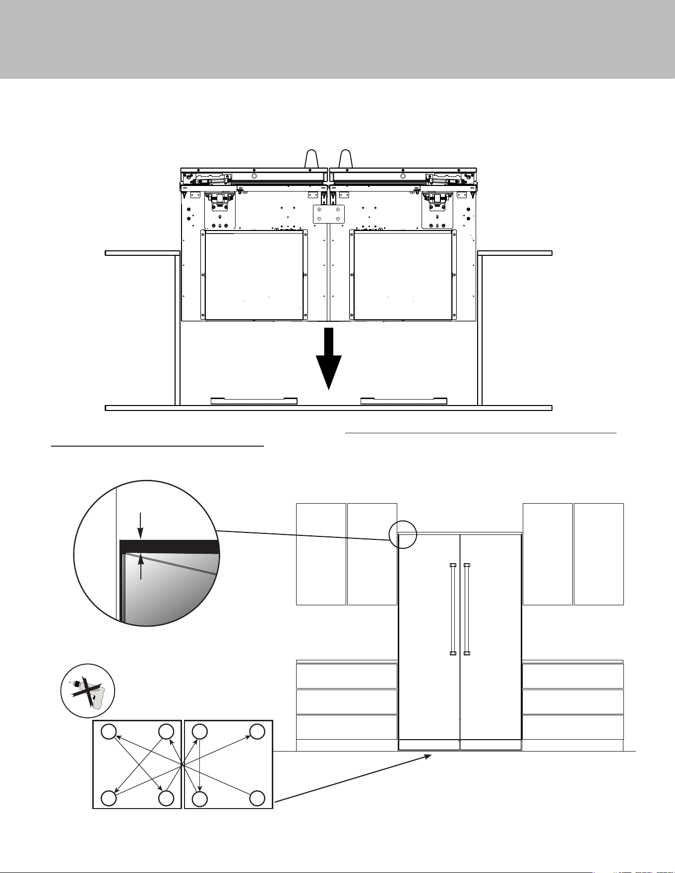
6. If unit leveling feet were used, lower units back onto rollers. Plug in electrical supply and roll connected units into cabinet
cutout. Units must be plugged into separate electric outlets. Connect water supply to each unit.
7. Lift units to desired height using 5/16” socket and hand ratchet. DO NOT USE A DRILL-(refer to lift pattern diagram below to
ensure that units are gradually lifted together.) **IMPORTANT** - Only make 4 turns at a time with the hand ratchet**. Attach
units to cabinet side trim using fasteners included with the units. Install stainless magnetic side trim once fastened. (Use
installation guide included with individual units as a reference.)
.125”
WHEN INSTALLED
2
7
6
3
4
5
8
1
FRONT
FRONT
REARREAR
Lift Pattern Diagram
11
Installation
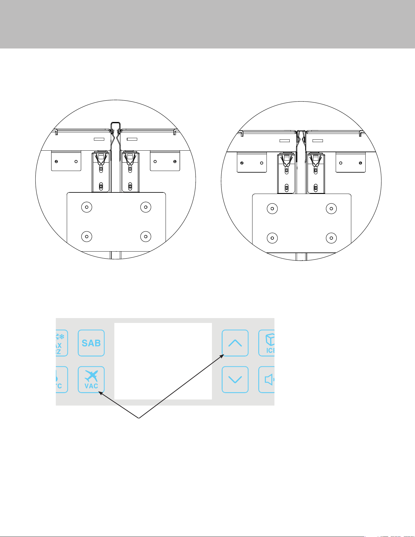
8. Remove plastic lm from center trim before installing. Install center connecting trim (Item #3) in between the two units by
pressing it in. Trim should be even with the top of the units. If needed, tap connecting trim gently into place with rubber
mallet.
NOTE: Open both doors to install the trim. When installed, the
face of the trim should be ush with the breaker frame.
9. Once the connection to the heater and the unit installation is complete, you will need to enable the heater which was plugged
into the right hand unit. (Step 4 on page 7).
To enable the heater, on the control panel* of the
right hand unit, press the VAC and UP arrow key and
hold for 5 seconds. You will hear an alarm beep once
when it accepts the entry.
*NOTE: Control panel may vary depending on model
being installed.
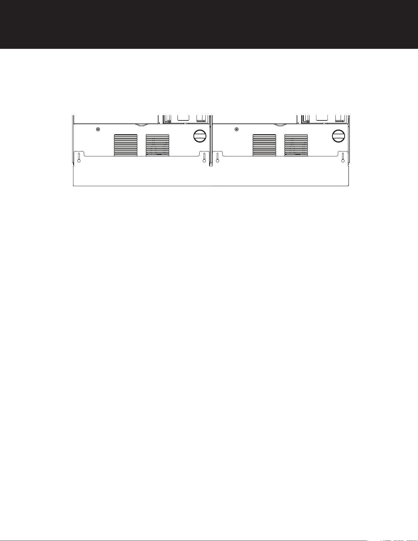
Optional Custom Kickplate Installation
Remove screws fastening individual kickplates on units. Save screws to be used when installing custom kickplate. Place custom
kickplate across bottom of both units and fasten using the mounting holes for the individual kickplates.
Viking Range, LLC
111 Front Street
Greenwood, Mississippi 38930
(662) 455-1200
For product information, call 1-888-845-4641
or visit our web site at vikingrange.com
067841-000C EN (103123)
