BELT DRIVE AIR COMPRESSORS WITH CAST
CYLINDERS 3.5HP
Thank you for purchasing a Sealey product. Manufactured to a high standard, this product will, if used according to these instructions,
and properly maintained, give you years of trouble free performance.
IMPORTANT: PLEASE READ THESE INSTRUCTIONS CAREFULLY. NOTE THE SAFE OPERATIONAL REQUIREMENTS, WARNINGS & CAUTIONS. USE
THE PRODUCT CORRECTLY AND WITH CARE FOR THE PURPOSE FOR WHICH IT IS INTENDED. FAILURE TO DO SO MAY CAUSE DAMAGE AND/OR
PERSONAL INJURY AND WILL INVALIDATE THE WARRANTY. KEEP THESE INSTRUCTIONS SAFE FOR FUTURE USE.
1. SAFETY
1.1. ELECTRICAL SAFETY
WARNING! It is the responsibility of the owner and the operator to read, understand and comply with the following: You must check all
electrical products before use to ensure that they are safe. You must inspect power cables, plugs, sockets and any other connectors for
wear or damage. You must ensure that the risk of electric shock is minimised by the installation of appropriate safety devices. A Residual
Current Circuit Breaker (RCCB) should be incorporated in the main distribution board. We also recommend that a Residual Current Device
(RCD) is used. It is particularly important to use an RCD with portable products that are plugged into a supply which is not protected by an
RCCB. If in any doubt consult a qualified electrician. You must also read and understand the following instructions concerning electrical
safety:
1.1.1. The Health & Safety at Work Act 1974 makes owners of electrical appliances responsible for the safe condition of those appliances and
the safety of the appliance operators. If in any doubt about electrical safety, contact a qualified electrician.
1.1.2. Ensure that the insulation on all cables and on the appliance is safe before connecting it to the power supply.
1.1.3. Ensure that cables are always protected against short circuit and overload.
1.1.4. Regularly inspect power supply cables and plugs for wear or damage and check all connections to ensure that none are loose.
1.1.5. IMPORTANT: Ensure that the voltage marked on the appliance matches the power supply to be used and that the plug is fitted with the
correct fuse.
▲ DANGER! If the power cable for this equipment is damaged, it must be replaced by the manufacturer or it’s after-sales service or similarly
trained personnel to avoid danger.
8 DO NOT pull or carry the appliance by the power cable.
8 DO NOT pull the plug from the socket by the cable.
8 DO NOT use worn or damaged cables, plugs or connectors. Immediately have any faulty item repaired or replaced by a qualified
electrician.
1.1.6. OVER-CURRENT PROTECTION: The user has to make provision for the installation of the over-current protection of the power circuit in
accordance with EN 60204-1:2006.
NOTE: If using a transformer to supply the compressor, it must be rated at a minimum of 2kVA to allow the compressor to run efficiently.
1.2. ELECTRICAL DISCONNECTING DEVICE
1.2.1. A reference to the supply disconnection device is to be in accordance with EN 60204-1:2006.
1.3. GENERAL SAFETY
9 Before you connect the equipment to the mains supply make sure that the data on the rating plate are identical to the mains data.
9 Familiarise yourself with the application and limitations of the compressor. Only instructed personnel shall use this appliance.
9 Ensure the compressor is in good order and condition before use. If in any doubt DO NOT use the unit and contact your Sealey
Stockist.
9 Operation must be with all guards, covers, lids and enclosures correctly in place.
9 Fully assemble the compressor before using for the first time.
9 The concentration of processed gases that can displace breathing air shall be kept within acceptable levels. Reference EN 12021 for
acceptable levels of contaminants in breathing air.
9 Remove from mains supply when performing maintenance or inspections.
WARNING! Item must be serviced by an authorised agent. DO NOT tamper with or attempt to adjust pressure switch or safety valve.
8 DO NOT carry out any welding operations on any pressurised part of the vessel.
9 Before moving, or maintaining the compressor ensure it is unplugged from the mains supply and that the air tank pressure has been
vented.
9 Maintain the compressor in good condition and replace any damaged or worn parts. Use genuine parts only. Unauthorised parts may
be dangerous and will invalidate your warranty.
WARNING! All hoses and ttings shall be suitable for site use at the maximum allowable pressure of the portable compressor. Delivery
hoses should be fitted with a safety cord.
WARNING! In the event that an airline is cut or broken, the air supply must be turned off at the compressor. A broken airline which is
not supported is extremely dangerous and can whip around very quickly, both with the capability of striking people and blowing foreign
particles into the air.
WARNING! It is essential to use separators, water traps and draining facilities to process liquids produced by the compressor before
putting the unit into use.
9 The compressor may only be used in suitable rooms (with good ventilation and an ambient temperature from +5°C to +40°C). Ensure there is
no dust, acids, vapours, explosive gases, or flammable gases in the room. The air intake should be from a clean, outside air source.
9 Read the instructions relating to any accessory to be used with this compressor.
Original Language Version
© Jack Sealey Limited
SAC1503B.V2 SAC1103B.V2 SAC1153B.V2 SAC1203B.V2 Issue:1 08/10/24
MODEL NO’s: SAC1503B.V2 SAC1103B.V2 SAC1153B.V2
SAC1203B.V2
Refer to
instructions
Wear eye
protection
Wear ear
protection
WARNING:
High Voltage
WARNING:
Hot surface
WARNING:
Automatic
start up
Indoor use only DO NOT open
the air cock
before an air
hose is attached
Work in progress Ensure oil level
is correct before
rst use
9 Ensure the safe working pressure of any air appliance used exceeds the compressors output pressure. If using a spray gun, check that
the area selected for spraying is provided with an air change system/ventilation.
WARNING! Ensure the air supply valve is turned o before disconnecting the air supply hose.
9 To move a transportable compressor use the handle only.
Lift the compressor so that the front leg gives enough clearance for manoeuvring but maintain unit’s centre of gravity in front of the
wheels. (if applicable). DO NOT attempt to lift or move the compressor by any other means.
9 Use the compressor in a well ventilated area and ensure it is placed on a rm surface.
9 Keep tools and other items away from the compressor when it is in use, and keep area clean and clear of unnecessary items.
9 Ensure the air hose is not tangled, twisted or pinched.
9 Keep children and unauthorised persons away from the working area.
9 Only move the compressor by the handle (if portable).
8 DO NOT disassemble compressor for any reason. The unit must be checked by qualied personnel only.
8 DO NOT use the compressor outdoors, or in damp, or wet, locations.
8 DO NOT operate within the vicinity of ammable liquids, gases or solids.
8 DO NOT touch compressor cylinder head or pipe from the head to tank as these may be hot. DO NOT remove covers.
8 DO NOT use this product to perform a task for which it has not been designed.
8 DO NOT deface the certication plate attached to the compressor tank.
8 DO NOT cover the compressor or restrict air ow around the unit whilst operating.
▲ DANGER! DO NOT direct the output jet of air towards people or animals.
8 DO NOT operate the compressor without an air lter.
8 DO NOT allow anyone to operate the compressor unless they have received full instructions.
WARNING! The air tank is a pressure vessel and the following safety measures apply:
8 DO NOT tamper with the safety valve, DO NOT modify or alter the tank in any way and DO NOT strap anything to the tank.
8 DO NOT subject the tank to impact, vibration or to heat and DO NOT allow contact with abrasives or corrosives.
9 Drain condensation from tank daily and inspect inside walls for corrosion every three months and have a detailed tank inspection
carried out annually. The tank shell must not fall below the certied thickness at any point.
WARNING! If an electrical fuse blows, ensure it is replaced with an identical fuse type and rating.
9 When not in use, store the compressor carefully in a safe, dry, childproof location.
9 When the compressor is not in use, it should be switched o, disconnected from the mains supply and the air drained from the tank.
9 Under the PRESSURE SYSTEMS SAFETY REGULATIONS 2000 it is the responsibility of the owner of the compressor to initiate a
system of inspection that both denes the frequency of the inspection and appoints a person who has specic responsibility for carrying
out the inspection.
WARNING! No welding operations are to be carried out on pressurised parts of the vessel.
WARNING! All hoses and ttings shall be suitable for the site use at the maximum allowable pressure of the portable compressor.
WARNING! The concentration of processed gases that can displace breathing air shall be kept within acceptable levels. Reference EN
12021 for acceptable levels of contaminants in breathing air.
WARNING! Ensure the oil level is regularly checked, and topped up if necessary to eliminate oil starvation. (See MAINTENANCE
section 6.3.1).
2. iINTRODUCTION
Suitable for the professional workshop, these units are fitted with a genuine 3.5hp motor. Twin capacitors and a centrifugal switch aid
trouble-free start-up on a 230V/13A supply (fitted with 3-pin plug). Pumps feature heavy-duty full cast cylinders, capped by alloy heads for
improved heat dissipation and long-life. Heavy-duty drive guards protect belt and flywheel that is designed to force air over the pump to
aid cooling.
3. iSPECIFICATION
Model No: SAC1503B.V2 SAC1103B.V2 SAC1153B.V2 SAC1203B.V2
Air Displacement cfm(L/min): 15cfm(425L/min) 15cfm(425L/min) 15cfm(425L/min) 15cfm(425L/min)
Fuse Rating: 13A 13A 13A 13A
Maximum Free Air Delivery cfm(L/min): 10.59cfm(300L/min) 10.59cfm(300L/min) 10.59cfm(300L/min) 10.59cfm(300L/min)
Maximum Pressure: 116psi(8bar) 116psi(8bar) 116psi(8bar) 116psi(8bar)
Minimum Rated Supply: 13A 13A 13A 13A
Motor Output: 3.5hp 3.5hp 3.5hp 3.5hp
Nett Weight: 58kg 74kg 85kg 101kg
Noise Level: 88dB 89dB 79dB 90dB
Oil Capacity: 1000ml 1000ml 1000ml 1000ml
Outlet: Quick release coupling Quick release coupling Quick release coupling Quick release coupling
Phase: 1ph 1ph 1ph 1ph
Plug Type: 3-Pin 3-Pin 3-Pin 3-Pin
Power Supply Cable Length: 1.8m 1.8m 1.8m 1.8m
Receiver Capacity: 50L 100L 150L 200L
Recommended Oil: Sealey FSO5 Sealey FSO5 Sealey FSO5 Sealey FSO5
Size (W x D x H): 920 x 420 X 840mm 1030 x 470 x 930mm 1220 x 480 x 950mm 1270 x 480 x 1020mm
Speed of pump: 1050rpm - 1100rpm 1050rpm - 1100rpm 1050rpm - 1100rpm 1050rpm - 1100rpm
Supply: 230V/13A 230V/13A 230V/13A 230V/13A
Applied Standards: EN 286-1: 1998/A2:2005
Original Language Version
© Jack Sealey Limited
SAC1503B.V2 SAC1103B.V2 SAC1153B.V2 SAC1203B.V2 Issue:1 08/10/24
4. ASSEMBLY
4.1. Remove compressor from packaging and inspect for shortages/damage. If items are missing or damaged contact your supplier.
4.2. Save the packing material for future transportation of the compressor. We recommend that you store the packing in a safe location, at
least for the period of the guarantee. Then, if necessary, it will be easier to send the compressor to the service centre.
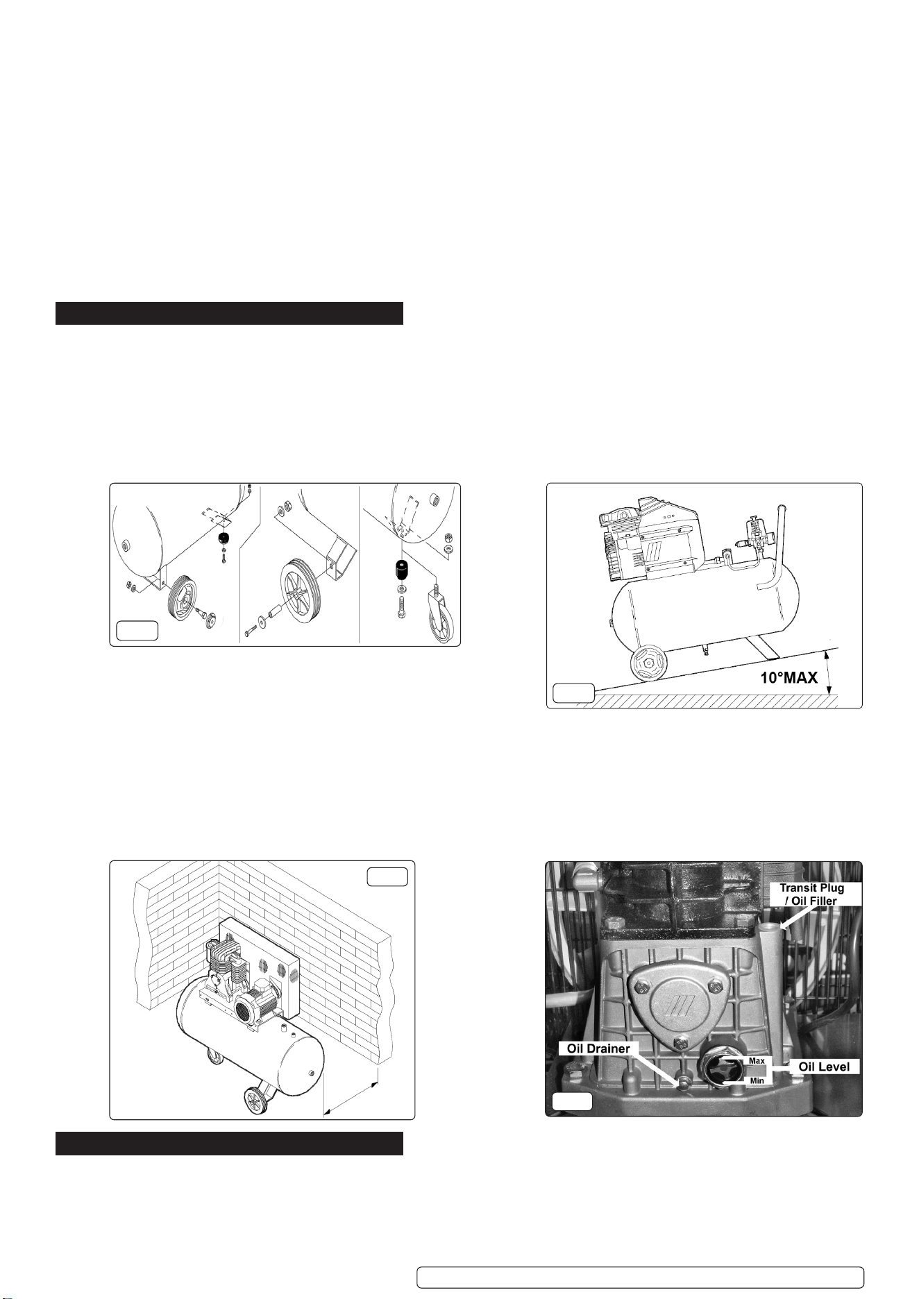
4.3. Assemble the xed wheels/castor wheel/rubber feet to the compressor as required (see g.1).
4.4. Confirm that the mains voltage corresponds with the voltage shown on the compressor data plate.
4.5. Position the compressor on a at surface or with a maximum permissible inclination of 10° (g.2). Site in a well ventilated area,
protected against atmospheric pollution and not in a place subject to explosion hazard. If the surface is inclined and smooth, check if
the compressor moves whilst in operation – if it does, secure the wheels with two wedges. If the surface is in a raised position, make
sure it cannot fall, securing it in a suitable way.
4.6. INSTALLING
4.7. To ensure good ventilation and ecient cooling, the compressor’s belt guard must be at least 100cm from any wall (g.3).
Compressors with xed feet should not be rigidly secured to the oor. In this case, it is advised to t 4 anti-vibration supports (optional
extra).
4.8. Take care to transport the compressor correctly, DO NOT overturn it or lift it with hooks or ropes.
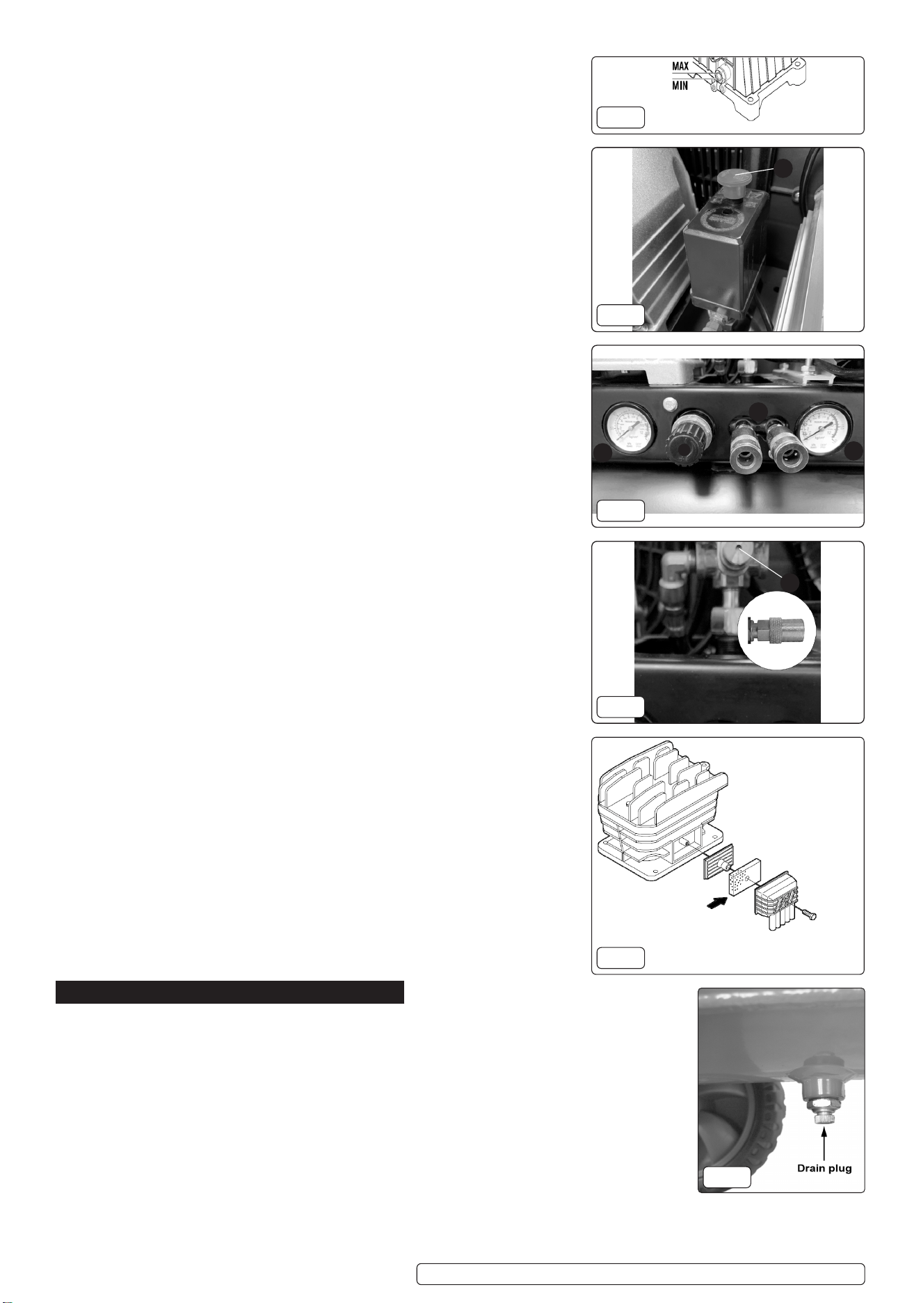
4.9. Remove the plastic transit plug from the oil filler hole (fig.4) and replace it with the filler/breather plug. It is a push fit, ensure that it is
pushed fully home. Make sure the drain valve under the air tank is closed, and the air filter shown in fig.9 is attached to the cylinder head.
4.10. Before using the compressor, add oil, we recommend using Sealey FSO5 synthetic oil. Observe the sight glass as shown in fig.4 for the
correct level. We DO NOT recommend using mineral oil in these compressors. DO NOT overfill.
5. OPERATION
WARNING! Ensure that you have read, understood and apply Section 1 Safety Instructions.
IMPORTANT! Use of extension leads to connect these compressors to the mains is not recommended as the resulting voltage drop
reduces motor and therefore pump performance, and could damage the compressor.
NOTE: Take care when selecting tools for use with the compressor.
Air tool manufacturers normally express the volume of air required to operate a tool in cubic feet per minute (cfm).This refers
to free air delivered by the compressor (‘air out’) which varies according to the pressure setting.
Additional Specication:
Short circuit current rating for each incoming power supply: 26A
Full load current for each incoming supply: 13A
Intended media: Air.
Inlet discharge pressure and temperatures: 8bar Temperature 120°C.
Maximum pressure ratio:1:8
Pressure limits of the lubrication system: 8bar.
Temperature limits of the lubrication system: 100°C.
Maximum speed of the unit: 2900RPM
Minimum speed of the unit: 2800RPM
Tank Thickness: 50L-2.5mm, 100L - 3.0mm, 150L - 3.0mm, 200L - 3.5mm
Noise Test Code: EN ISO 2151:2008
Pressure and ow rate. (Pressure relief device.) The safety valve will open at 8.8Bar (1.1 times of max working pressure).
Flow rate 2960 L /M.
Environmental limitations - 10°C - 35°C.
Original Language Version
© Jack Sealey Limited
SAC1503B.V2 SAC1103B.V2 SAC1153B.V2 SAC1203B.V2 Issue:1 08/10/24
fig.1
fig.2
fig.3
fig.4
Illustration only
100cm
DO NOT confuse this with the compressor displacement which is the air taken in
by the compressor (‘air in’). ‘Air out’ is always less than ‘air in’ due to losses within
the compressor.
WARNING! The compressor is supplied without oil in it. The oil is in a separate
container. Remove the transit plug from the oil ller aperture, pour oil into the
aperture until it has reached the correct level on the sight glass g.4.
5.1. STARTING / STOPPING THE COMPRESSOR
5.1.1. To turn the compressor on use the switch seen in photo (gs.6.1). pull the switch up
to position ‘I’ to start the compressor and down to position ‘O’ to stop it.
5.1.2. Check that the ON/OFF switch is in the ‘O’ position. The regulator tap (g.7.2)
should be closed and the output gauge (g.7.4) must read Zero ‘0’ bar.
5.1.3. Plug into mains supply and start the compressor by pulling the switch up to the ‘I’
position.
5.1.4. When starting the compressor for the first time, leave it running with no air tools
connected to the air outlet. Make sure that pressure in the tank rises and that the
compressor stops automatically when the maximum pressure value allowed - written
on the plate and shown on the gauge (fig.7.5) - is achieved. The compressor will
now operate automatically. The pressure switch stops the motor when the maximum
tank pressure is reached and restarts it when the pressure falls below the minimum
threshold - approx. 5 bar (72.5psi) less than the maximum pressure.
5.1.5. Stop the compressor by pushing the main switch to the ‘O’ position. The
compressed air inside the compressor head will flow out, making the restart easier
and preventing the motor from being damaged.
5.2. EMERGENCY STOP
8 DO NOT, other than in an emergency, stop the compressor by switching off at the
mains socket, or by pulling the plug out, as the pressure relief will not then operate
and motor damage may result upon restart.
5.3. Disconnect compressor from the mains power supply after use.
5.4. Set the outlet pressure on the regulator to zero.
5.5. Remove the air line and air tool.
5.6. The tank must now be drained. Release the air left in the tank. After, drain away
condensation that may have formed within the tank. Choose a suitable location for
this operation and/or make provision to collect the condensation.
IMPORTANT: Wear ear and eye protection.
WARNING! Water that is allowed to remain in the tank during storage will corrode
and weaken the air tank, which could cause the tank to rupture. To avoid serious
injury, drain the tank on a daily basis.
5.7. SAFETY FEATURES
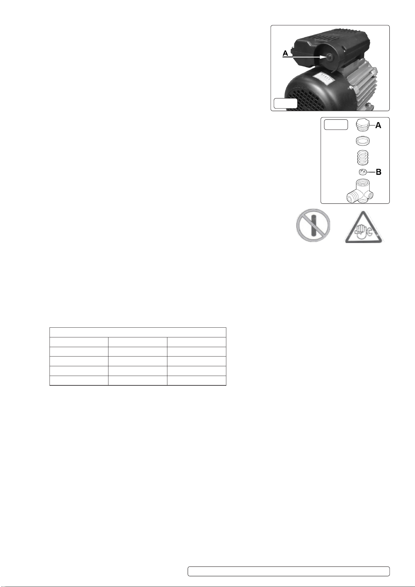
5.7.1. The motor of the compressor is fitted with a thermal breaker located in the housing
on top of the motor. The manual resetting button is located in the end of the housing
as shown in fig.11A. When the breaker is tripped, wait for a few minutes and then
press the reset button.
5.7.2. The output pressure is regulated by the pressure regulator (fig.7.2). Turn the knob
clockwise to increase pressure and anticlockwise to reduce it. Lock knob in position
at required pressure with locking ring. To determine the correct working pressure for
any piece of equipment, check the corresponding manual. When the compressor
is not being used, set the regulated pressure to zero so as to avoid damaging the
pressure regulator.
NOTE:
A) If the motor does not cut in and out, but runs continuously when using an air
appliance, the capacity of the compressor may be too small for the equipment or
tool.
B) The gauge (fig.7.5) indicates the pressure inside the main tank, NOT the
pressure supplied to the air equipment, which is shown on the other gauge (fig.7.4).
Should the pressure in the main tank exceed the pre-set switch maximum, the
safety valve (fig.8.5) will activate.
WARNING! DO NOT tamper with, or adjust, the switch or safety valve.
6. MAINTENANCE
6.1. ACTIONS TO PREVENT STARTING AUTOMATICALLY OR FROM A REMOTE
POSITION WHEN THE COMPRESSOR IS BEING SERVICED, MAINTAINED OR
INSPECTED
WARNING! Before performing any maintenance operation, switch off the
compressor, disconnect from electricity supply and release all air from the tank. In
order to keep the compressor in good working condition, periodic maintenance is
essential.
6.2. Regular periodic maintenance on your air compressor will ensure its optimum
performance. Make a habit of inspecting the following items before each time you
use the air compressor.
6.3. CHECK THE FOLLOWING ITEMS
6.3.1. Check oil level! Use the sight gage on the bottom of the crankcase to make sure
the oil level is at the proper height.
Original Language Version
© Jack Sealey Limited
SAC1503B.V2 SAC1103B.V2 SAC1153B.V2 SAC1203B.V2 Issue:1 08/10/24
fig.5
fig.6
fig.7
fig.9
fig.10
1
fig.8
3
4
5
5
2
6.3.2. Drain the tank of any condensation by opening the drain valve on the bottom of the
tank. NOTE: Depending upon the amount of use and weather conditions, a certain
amount of condensed water may be released. For longevity of the compressor seals
and the air tools you connect, it is best to keep the tank free of water.
The tank is best drained if the drain valve is opened when the system is slightly
pressurised. Once water has stopped coming out, you can close the drain valve.
6.3.3. Clean off cylinder head cooling fins of any dirt which might hamper air flow.
6.3.4. Check for worn or damaged cords and plugs.
6.3.5. Check for any other condition that could hamper the safe operation of the
compressor.
6.4. CLEANING THE AIR FILTER
6.4.1. The air filter prevents dust and dirt being drawn in. It is essential to clean the
filter at least after every 300 hours in service. Clogged air filters will decrease the
performance of the compressor dramatically. See fig.9.
IMPORTANT WARNING - Air contaminants taken into the compressor will aect
optimum performance.
Example: Body ller dust or paint overspray will clog the pump intake lter and
may cause internal damage to pump/motor components. Please note that any
parts damaged by any type of contamination will not be covered by warranty.
6.5. SAFETY RELIEF VALVE
6.5.1. The safety relief valve in fig.8 has been set for the highest permitted pressure of the
tank. It is prohibited to adjust the safety relief valve or to remove it’s seal. The safety
relief valve works automatically and requires no maintenance by the user.
6.6. VEE-BELTS, PRESSURE SWITCHES, ELECTRICAL COMPONENTS
WARNING! Please refer any maintenance of vee-belts, pressure switches, electrical
components and pump to qualified compressor technicians.
WARNING! Restrict availability of keys or tools to skilled or instructed persons only.
Maintenance will only be carried out by trained personnel.
IMPORTANT! Failure to carry out maintenance tasks may invalidate the warranty
on your compressor.
WARNING! Display warning signs (see alongside) against reconnection whilst the
compressor is being repaired such as:
8 DO NOT START. MAINTENANCE WORK IN PROGRESS.
6.7. AFTER THE FIRST 10 HOUR OF USE
6.8. After the rst 10 working hours or 30 days, whichever comes rst, perform the following maintenance:
6.8.1. Replace the oil in the pump with approved compressor oil (Use ISO 100 viscosity, non detergent type, Synthetic oil suitable for
temperatures ranging from -5°C to 45°C:).
6.8.2. Make sure that all the ttings are tight and re-torque the cylinder head bolts according to the table below. If you are unsure of this refer
the unit to a qualied compressor technician.
6.8.3. Remove the air lter foam element and rinse it out with water. Allow it to dry and re-install.
6.8.4. Blow out any accumulated dirt between the cylinder cooling ns.
6.9. PREVENTING THE RISK OF OIL FIRES
6.9.1. One of the primary causes of air compressor res is oil or lubricant breakdown. Over time, the oil inside the compressor can degrade
and become highly ammable, especially at higher temperatures. This can lead to a dangerous build up of heat, increasing the risk of a
re. It is important to regularly inspect and maintain the components of the compressor to minimize the risk of re.
6.10. PREVENTATIVE MAINTENANCE FOR FIRE SAFETY
6.10.1. Proper preventative maintenance plays a crucial role in ensuring the safe and ecient operation of an air compressor. To minimize the
risk of re, it is essential to conduct regular inspections and adhere to the manufacturer’s recommended maintenance schedule. This
includes checking for any signs of wear and tear, such as frayed wires, leaking uids, or damaged components, and addressing issues
promptly.
6.11. WEEKLY
6.11.1. If the compressor is used on a daily basis, perform the following checks each week:
6.11.2. Rinse the air lter foam element in water.
6.11.3. Check for loose bolts or ttings.
6.12. EVERY 300 HOURS
6.13. After every 300 hours or 3 months of regular operation, perform the following maintenance items:
6.13.1. Replace the oil in the pump with approved compressor oil (Use ISO 100 viscosity, non detergent type, Synthetic oil suitable for
temperatures ranging from -5°C to 45°C:).
6.13.2. Rinse the air filter foam element in water.
6.13.3. Check for air leaks and correct as needed.
6.13.4. Clean the cylinder head fins for proper cooling.
6.13.5. Check for loose bolts or fittings.
Original Language Version
© Jack Sealey Limited
SAC1503B.V2 SAC1103B.V2 SAC1153B.V2 SAC1203B.V2 Issue:1 08/10/24
Torque ranges for tightening head bolts
Bolt size Min Torque Max torque
M8 22.45Nm 27.43Nm
M10 45.28Nm 55.34Nm
M12 77.10Nm 94.23Nm
M14 123.00Nm 150.37Nm
MAINTENANCE
WORK IN
PROGRESS
DO NOT START
fig.11
fig.12
6.14. INSPECTION OF PRESSURE TANK BOTH INSIDE AND OUT
6.14.1. Under the PRESSURE SYSTEMS SAFETY REGULATIONS 2000 it is the responsibility of the owner of the compressor to initiate a
system of inspection that both defines the frequency of the inspection and appoints a person who has specific responsibility for carrying
out the inspection.
6.15. STORAGE WHEN NOT IN USE
6.16. When storing your air compressor follow these guidelines:
6.17. Set the ON/OFF button to OFF.
6.18. Turn the regulator counterclockwise to set the delivery pressure to zero.
6.19. Disconnect air tools or accessories.
6.20. Pull the safety drain valve to bleed excess pressure from tank. The pressure gauge for the tank should read just under 1bar.
6.21. Drain water from the tank by opening the drain valve on the bottom of the tank.
6.22. Close the drain valve when all the water has been released.
6.23. Store the air compressor in its normal operating position in a cool and dry, childproof location.
6.24. TRANSPORT
9 Remove air from tank before transporting the compressor.
WARNING! Care must be taken when transporting the compressor, use the lift handle and transport wheels (if applicable).
6.25. SUPPLY CORDS
6.26. If the replacement of the supply cord is necessary, this has to be done by the manufacturer or a Sealey Service Agent in order to avoid
a safety hazard.
6.27. PIPING SYSTEM
WARNING! If connecting the compressor to a pipe system a exi pipe must be installed at the start of the system.
6.28. RESTARTING THE COMPRESSOR AFTER AN UNEXPECTED STOP
6.28.1. Before restarting the compressor:
6.28.2. Check for oil leaks.
6.28.3. Check oil quantity levels. This can be done by inspecting the level in the sight glass.
6.28.4. Check drive belts are free and are not damaged.
6.28.5. Make sure the electrical cable/plug is not damaged. Check fuse in plug If compressor does not restart.
6.28.6. Check the thermal breaker, reset if required. See 5.7.1 for resetting.
6.28.7. If you are concerned about any of your ndings from performing these checks then contact Sealey Service Centre who will be able to
assist you in rectifying them.
6.29. REMOVING COMPRESSOR FOR SERVICING OR REMOVAL
6.29.1. Space required for the removal or servicing. Allow 30cm minimum free space around the machine.
7. TROUBLE SHOOTING
Sealey Group, Kempson Way, Suffolk Business Park, Bury St Edmunds, Suffolk. IP32 7AR
01284 757500 sales@sealey.co.uk www.sealey.co.uk
Note: It is our policy to continually improve products and as such we reserve the right to alter data, specifications and component parts without prior
notice. Please note that other versions of this product are available. If you require documentation for alternative versions, please email or call our
technical team on technical@sealey.co.uk or 01284 757505.
Important: No Liability is accepted for incorrect use of this product.
Warranty: Guarantee is 12 months from purchase date, proof of which is required for any claim.
WEEE REGULATIONS
Dispose of this product at the end of its working life in compliance with the EU Directive on Waste Electrical and Electronic Equipment
(WEEE). When the product is no longer required, it must be disposed of in an environmentally protective way. Contact your local solid
waste authority for recycling information.
ENVIRONMENT PROTECTION
Recycle unwanted materials instead of disposing of them as waste. All tools, accessories and packaging should be sorted,
taken to a recycling centre and disposed of in a manner which is compatible with the environment. When the product
becomes completely unserviceable and requires disposal, drain any fluids (if applicable) into approved containers and
dispose of the product and fluids according to local regulations.
REGISTER YOUR
PURCHASE HERE
Original Language Version
© Jack Sealey Limited
SAC1503B.V2 SAC1103B.V2 SAC1153B.V2 SAC1203B.V2 Issue:1 08/10/24
Fault Cause Remedy
Pressure drop in the tank. Air leaks at connections. Run compressor to max. pressure, switch off. Brush soap solution over connections and
look for bubbles. Tighten connections showing leaks. If problem persists contact Authorised
Service Agent.
Pressure switch valve leaks when
compressor is idle.
Non-return valve seal defective. Discharge all tank pressure. Referring to fig.12, unscrew valve cap 'A'. Clean rubber disc 'B'
and its seat. Refit all parts accurately.
Compressor stops and does not
restart.
Power failure.
Motor failure.
Check electricity supply and fuse.
Contact Authorised Service Agent.
Compressor does not stop at max
pressure.
Pressure switch fault. Contact Authorised Service Agent.
Compressor does not reach max
pressure.
Filter clogged.
Head gasket or valve fault.
Replace filter element.
Contact Authorised Service Agent.
Compressor noisy with metallic
knock.
Low oil level.
Bearing or piston damage.
Turn off and top up oil immediately.
Contact Authorised Service Agent.
