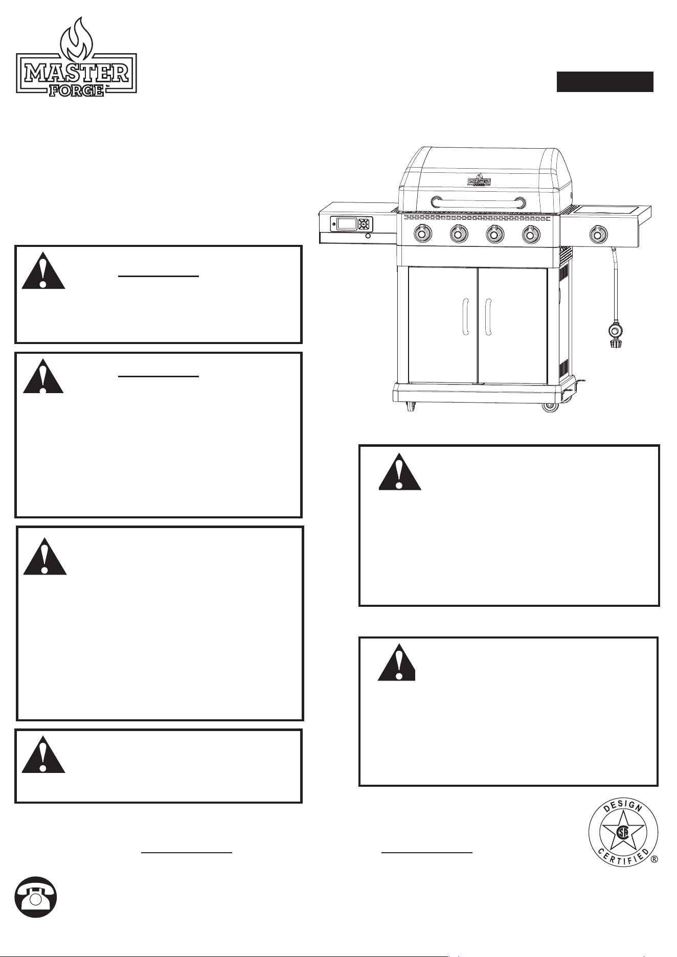
ITEM#4082879
4 BURNER GAS GRILL WITH SIDE BURNER & INTEGRATED CONTROLLER
MODEL#GBC22483L
ATTACH YOUR RECEIPT HERE
Serial Number Purchase Date
WARNING
FOR YOUR SAFETY:
For Outdoor Use Only
(outside any enclosure)
WARNING
FOR YOUR SAFETY:
Improper installation, adjustment, alteration,
service or maintenance can cause injury or
property damage. Read this instruction manual
thoroughly before installing or servicing this
equipment.
DANGER
If you smell gas:
• Shut off gas to appliance.
• Extinguish any open flame.
• Open lid.
• If odor continues, keep away from the appliance
and immediately call your gas supplier or your fire
department.
WARNING
• Do not store or use gasoline or other flammable
liquids or vapors in the vicinity of this or any other
appliance.
• An LP cylinder not connected for use shall not
be stored in the vicinity of this or any other
appliance.
DANGER
Never operate this appliance unattended.
GBC22483L-RA-OM-F103
MASTER FORGE and logo design are trademarks or registered trademarks of LF, LLC. All rights reserved.
WARNING:
This product can expose
you to chemicals including carbon monoxide, soot,
lead and lead components, which are known to
the State of California to cause cancer and birth
defects or other reproductive harm. For more
information go to www.P65Warnings.ca.gov.
Questions, problems, missing parts? Before returning to your retailer, call our
customer service department at 1.800.963.0211, 8 a.m. - 8 p.m., EST, Monday -
Sunday. You could also contact us at [email protected].
AS22033
Español p.34

2
W The use and installation must conform with local codes or,
in the absence of local codes, with either the National Fuel
Gas Code, ANSI Z223.1/NFPA 54, or the Natural Gas and
Propane Installation Code, CSA B149.1,or the Propane
Storage and Handling Code, CSA B149.2, or the Standard
for Recreational Vehicles, ANSI A 119.2/NFPA 1192, and
CSA Z240 RV Series, Recreational Vehicle Code, as
applicable.
W This grill is for outdoor use only, and should not be used in
a building, garage or any other enclosed area.
W Do NOT operate, light or use this appliance within ten feet
(3.05 m) of walls, structures or buildings.
W For residential use only. This grill is NOT for commercial
use.
W This grill is not intended for and should never be used
as a heater. TOXIC fumes can accumulate and cause
asphyxiation.
W This grill is safety certified for use in the United States
and/or Canada only. Do NOT modify for use in any other
location. Modification will result in a safety hazard and will
void your warranty.
W This grill is for use with liquid propane (LP) gas only. The
conversion to or attempted use of natural gas in this LP gas
grill is dangerous, may cause bodily harm and will void your
warranty.
W LP gas characteristics:
a. LP gas is flammable and hazardous if handled
improperly. Become aware of the characteristics
before using any LP gas product.
b. LP gas is explosive under pressure, heavier than air,
and settles/pools in low areas.
c. LP gas in its natural state has no odor. For your safety,
an odorant is added that smells like rotten cabbage.
d. Contact with LP gas can cause freeze burns to skin.
W Apartment dwellers: Check with management to learn the
requirements and fire codes for using a LP gas grill in your
apartment complex. If allowed, use outside on the ground
floor with a ten foot (3.05 m) clearance from any structure.
Do NOT use on or under balconies.
W LP gas cylinder needed to operate. Only cylinders marked
“propane” may be used.
W The LP gas cylinder must be:
a. constructed and marked in accordance with the
Specifications for LP-gas Cylinders of the U.S.
Department of Transportation (D.O.T.) or the
standard for Cylinders, Spheres and Tubes for the
Transportation of Dangerous Goods and Commission,
CAN/CSA-B339, as applicable; and
b. provided with a listed overfilling prevention device.
TABLE OF CONTENTS
Safety Information.................................... 2
Package Contents .................................... 5
Hardware Contents .................................... 6
Preparation . . . . . . . . . . . . . . . . . . . . . . . . . . . . . . . . . . . . . . . . . . 6
Assembly Instructions .................................. 7
Installation Instructions . . . . . . . . . . . . . . . . . . . . . . . . . . . . . . . . 22
Operating Instructions................................. 23
Care and Maintenance ................................ 29
Limited Warranty ..................................... 31
Troubleshooting ..................................... 31
Replacement Parts List ............................. 33
W DANGER: Failure to follow the dangers, warnings and cautions in this manual may result in serious bodily injury or death, or in
a fire or an explosion causing damage to property.
W WARNINGS:
SAFETY INFORMATION

3
c. provided with a cylinder connection device compatible
with the connection for outdoor cooking appliances.
W LP gas cylinder must be arranged for vapor withdrawal.
W The LP gas cylinder must have a listed overfilling
prevention device (OPD).
W Only use LP gas cylinders equipped with a cylinder
connection device compatible with the connection for
outdoor cooking appliances.
W The LP gas cylinder must have a cylinder collar to protect
the cylinder valve.
W Never use an LP gas cylinder with a damaged body, valve,
collar or footing.
W Dented or rusted LP gas cylinders may be hazardous and
should be checked by your LP gas supplier prior to use.
W The LP gas cylinder should not be dropped or handled
roughly.
W LP gas cylinders must be stored outdoors out of the reach
of children and must not be stored in a building, garage
or any other enclosed area. Your cylinder must never be
stored where temperatures can reach over 125°F.
W Do NOT insert any tool or foreign object into the valve
outlet or safety relief valve. You may damage the valve and
cause a leak. Leaking propane may result in an explosion,
fire, severe personal injury or death.
W Do NOT block holes in sides or back of grill.
W Never keep an LP gas cylinder in a hot car or trunk. Heat
will cause the gas pressure to increase, which may open
the relief valve and allow gas to escape.
W Place dust cap on cylinder valve outlet whenever the
cylinder is not in use. Only install the type of dust cap on
the cylinder valve outlet that is provided with the cylinder
valve. Other types of caps or plugs may result in leakage of
propane.
W If grill is not in use, the gas must be turned off at the supply
cylinder and disconnected.
W Do NOT store a spare LP gas cylinder under or near this
appliance.
W Never fill the cylinder beyond 80 percent full. A fire causing
serious injury or damage to property may occur if the
above is not followed exactly.
W Never attempt to attach this grill to the self-contained LP
gas system of a camper trailer, motor home or house.
W Never use charcoal, lighter fluid, lava rocks, gasoline,
kerosene or alcohol with this product.
W Your grill has been checked at all factory connections
for leaks. Re-check all connections as described in the
“Operating Instructions” section, as shipping can loosen
connections.
W Check for leaks even if your unit was assembled for you by
someone else.
W Do NOT operate if a gas leak is present. Gas leaks may
cause a fire or explosion.
W You must follow all instructions in the “Checking for Leaks”
section before operating. To prevent fire or explosion
hazard when testing for a leak:
a. Always perform a leak test before lighting the grill and
each time the cylinder is connected for use.
b. No smoking. Do NOT use or permit sources of ignition
in the area while conducting a leak test.
c. Conduct the leak test outdoors in a well-ventilated
area.
d. Do NOT use matches, lighters, or a flame to check for
leaks.
e. The use of alcohol, prescription or non-prescription
drugs may impair the consumer’s ability to properly
assemble or safely operate the appliance.
f. Strong odors, colds, sinus congestion, etc. may
prevent the detection of propane. Use caution and
common sense when testing for leaks.
g. Do NOT use grill until any and all leaks are corrected.
If you are unable to stop a leak, disconnect the LP gas
supply. Call a gas appliance serviceman or your local
LP gas supplier.
W This grill is designed to operate at an inlet pressure of: 11
inches water column.
W Do NOT store or use gasoline or other flammable liquids or
vapors within 25 feet (7.62 m) of this appliance.
W Do NOT use in an explosive atmosphere. Keep grill area
clear and free from combustible materials, gasoline and
other flammable vapors and liquids.
W Minimum clearance from sides and back of unit to
combustible construction is 36 inches (91.5 cm). Do NOT
use this appliance under any type of overhang or roof.
W It is essential to keep the grill’s valve compartment, burners
and circulating air passages clean.
W Inspect grill before each use.
W Do NOT alter grill in any manner. Any alteration will void
your warranty.
W Do NOT use the grill unless it is COMPLETELY assembled
and all parts are securely fastened and tightened.
W Do NOT build this model of grill in any built-in or slide-in
construction. Ignoring this warning could cause a fire or
an explosion that can damage property and cause serious
bodily injury or death.
W This grill should be thoroughly cleaned and inspected on a
regular basis.
SAFETY INFORMATION

4
W Clean and inspect the hose before each use of the
appliance. If there is evidence of abrasion, wear, cuts or
leaks, the hose must be replaced prior to operation.
W Use only the regulator and hose assembly provided.
Use only the replacement regulator and hose assembly
specified by RevoAce Inc. Limited.
W Use only RevoAce Inc. Limited factory-authorized parts.
The use of any part that is not factory-authorized can be
dangerous and will void your warranty.
W Do NOT operate this appliance without reading “Operating
Instructions” in this manual.
W Do NOT touch metal parts of grill until they have completely
cooled to avoid burns, unless you are wearing protective
gear (pot holders, gloves, BBQ mittens, etc.).
W Do NOT install or use in or on boats or recreational
vehicles.
W When cooking, fire extinguishing materials should be
readily accessible. In the event of an oil/grease fire, do
NOT attempt to extinguish with water. Use type BC dry
chemical fire extinguisher or smother with dirt, sand or
baking soda.
W Do NOT use grill in high winds.
W Never lean over the grill when lighting.
W Do NOT leave a lit grill unattended. Keep children and pets
away from grill at all times.
W Do NOT leave grill unattended while preheating or burning
off food residue on high. If grill has not been cleaned, a
grease fire can occur that may damage the product.
W Do NOT place empty cooking vessels on the appliance
while in operation.
W Use caution when placing anything on the grill while the
appliance is in operation.
W Do NOT attempt to move grill when in use. Allow the grill to
cool before moving or storing.
W LP gas cylinder must be properly disconnected and
removed prior to moving this grill.
W Storage of grill indoors is permissible only if the cylinder is
disconnected, removed from the grill and properly stored
outdoors.
W Always open grill lid carefully and slowly as heat and steam
trapped within grill can cause severe burns.
W Do NOT attempt to disconnect the gas regulator from the
cylinder or any gas fitting while the grill is in use.
W Always place your grill on a hard, non-combustible,
level surface. An asphalt or blacktop surface may not be
acceptable for this purpose.
W Move gas hoses as far away as possible from hot surfaces
and dripping hot grease.
W Keep all electrical cords away from a hot grill.
W After a period of storage and/or nonuse, check for leaks,
burner obstructions and inspect for any abrasion, wear or
cuts to the hose.
W Failure to open lid while igniting the grill’s burners, or not
waiting 5 minutes to allow the gas to clear if the grill does
not light, may result in an explosive flame-up.
W Never operate grill without its heat plates installed.
W Always use a meat thermometer to ensure food is cooked
to a safe temperature.
W Use protective gloves when assembling this product.
W Never turning the grill to high, and letting it run for a while.
W Do NOT force parts together as this can result in personal
injury or damage to the product.
W Never cover entire cooking area with aluminum foil. Laying
the foil on the grates can restrict the intended air flow inside
the grill, create barriers to the proper flow of grease to the
catch pan, which sets the stage for lots of it to build up
on the bottom tray, which in turn, builds the potential for
grease fires and flare ups.
W Deaths, serious injury or damage to property may occur if
the above is not followed exactly.
SAFETY INFORMATION
5
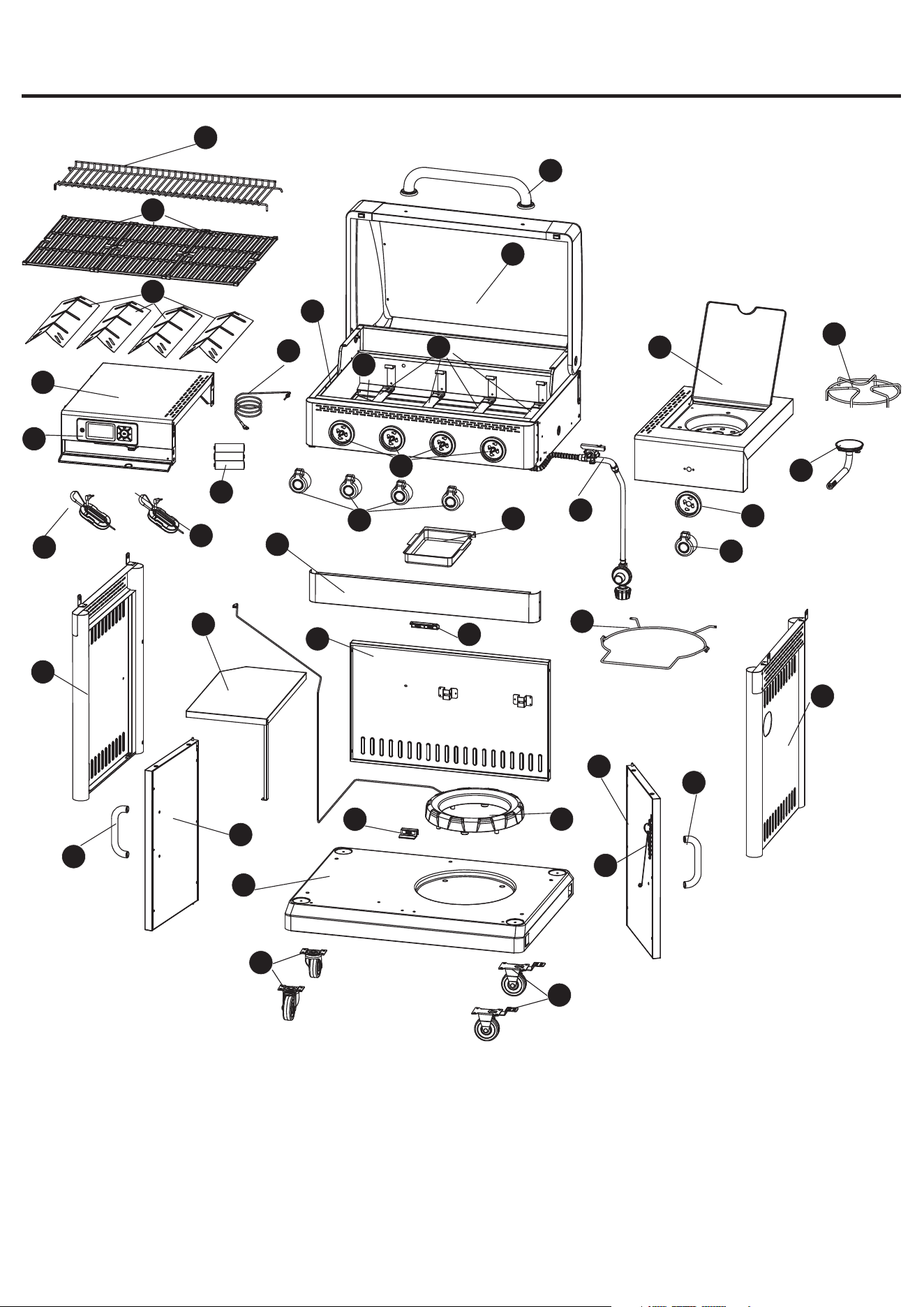
PACKAGE CONTENTS
A
V
D
G
W
X
H
I
B
U
J
E
O
P
C
F
K
L
N
Z
T
AE
R
AF
AC
AB
AA
AD
AI
AH
AG
Q
S
O
Y
M
AA
N
AJ
AK
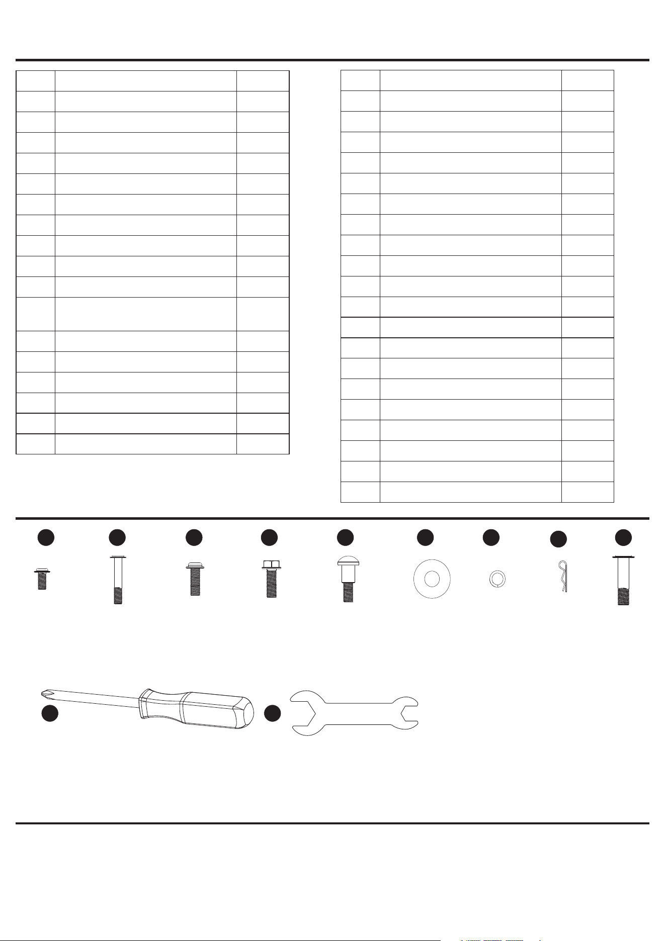
6
M4x10
Screw
Qty:16
M4x35
Screw
Qty:4
M6x16
Screw
Qty:25
M6x16
Screw
Qty:12
M6x22
Screw
Qty:3
Ø16
Washer
Qty:6
Ø6
Lock Washer
Qty:6
AA BB CC DD EE FF GG
#2 Philips Head
Screwdriver
Qty:1
M6-M10
Wrench
Qty:1
Before beginning assembly of product, make sure all parts are present. Compare parts with package
contents list and hardware contents list. If any part is missing or damaged, do not attempt to assemble the
product.
Estimated assembly time: one hour by two people
Toos required for assemly: Wrench and Philips screwdriver (included).
PACKAGE CONTENTS
HARDWARE CONTENTS
Preparation
JJ KK
Ø1.4
Cotter Pin
Qty:2
HH
Part Description Quantity
A Warming Rack 1
B Cooking Grid 3
C Heat Plate 4
D Lid Handle 1
E Lid* 1
F Back Ambient Probe 1
G Grill Body Assembly* 1
H Main Burner* 4
I Grease Tray* 1
J Left Side Shelf 1
K Digital Controller* 1
L Food Probe A 1
M Food Probe B 1
N Control Knob Bezel 5
O Control Knob 5
P Regulator & Hose Assembly* 1
Q Right Side Shelf 1
* Pre-assembled
II
M6x35
Screw
Qty:2
Part Description Quantity
R Side Burner Grid 1
S Side Burner 1
T Grease Cup 1
U Left Cart Frame 1
V Upper Front Panel 1
W LP Gas Retainer Wire 1
X Right Cart Frame 1
Y Center Table 1
Z Back Cart Frame 1
AA Door Handle 2
AB Left Door 1
AC Propane Tank Scale 1
AD Right Door 1
AE Lighing Rod* 1
AF Lower Magnet 1
AG Bottom Panel 1
AH Caster 2
AI Locking Caster 2
AJ Upper Magnet 1
AK Battery 3
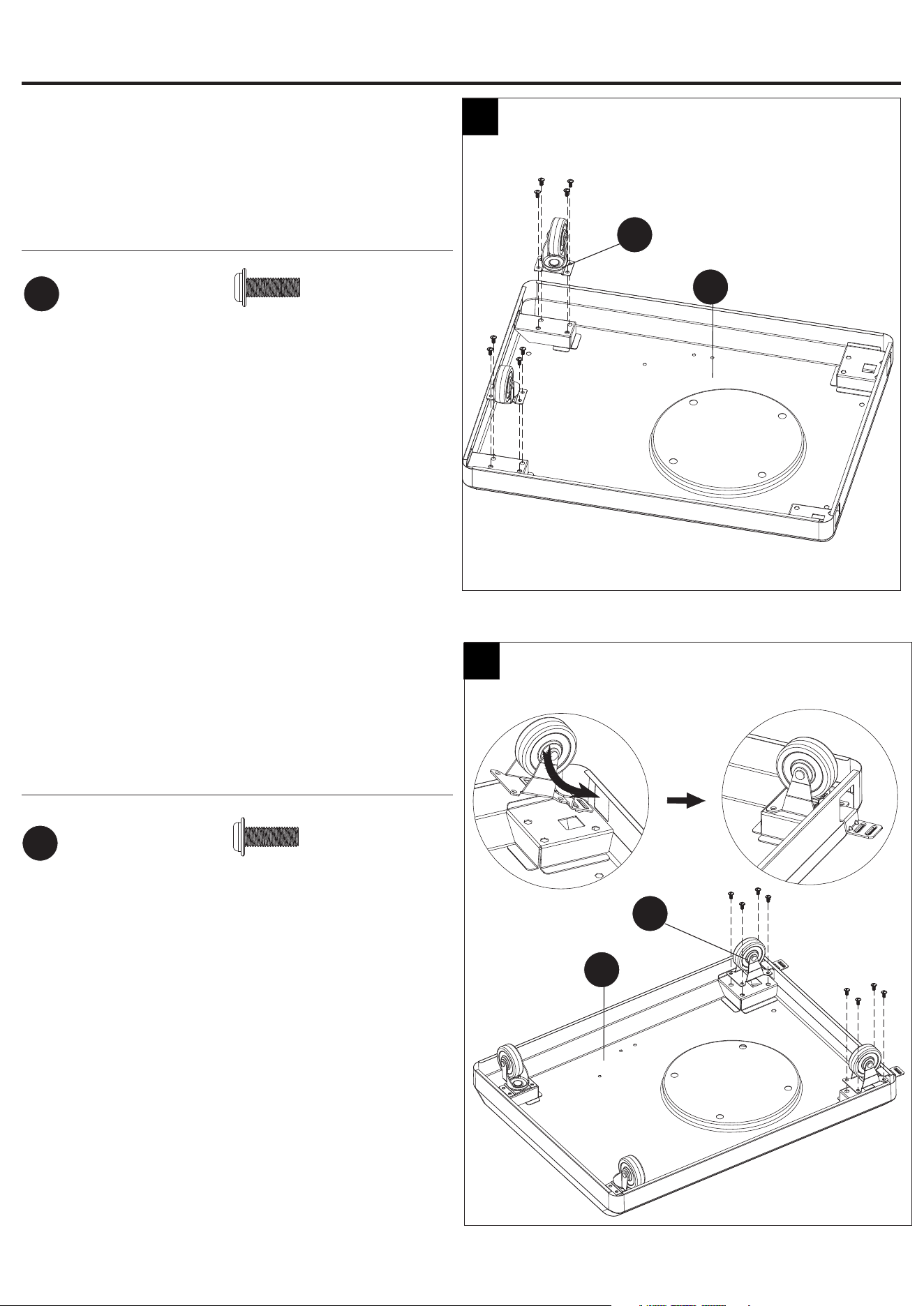
7
Step 1: Install Casters on Bottom Panel
Align the holes in the casters (AH) and bottom panel (AG). Then
insert the M6*16 screw (CC) into the holes shown in Fig.1.
Tighten both screws complelely.
Hardware Used
AG
1
AH
M6x16
Screw
CC
x 8
Step 2: Install Locking Casters on Bottom Panel
Align the holes in the locking casters (AI) and bottom panel
(AG). Then insert the M6*16 screw (CC) into the holes shown in
Fig.2. Tighten both screws complelely.
Hardware Used
2
ASSEMBLY INSTRUCTIONS
AI
AG
M6x16
Screw
CC
x 8
M6x35
Screw
Qty:2
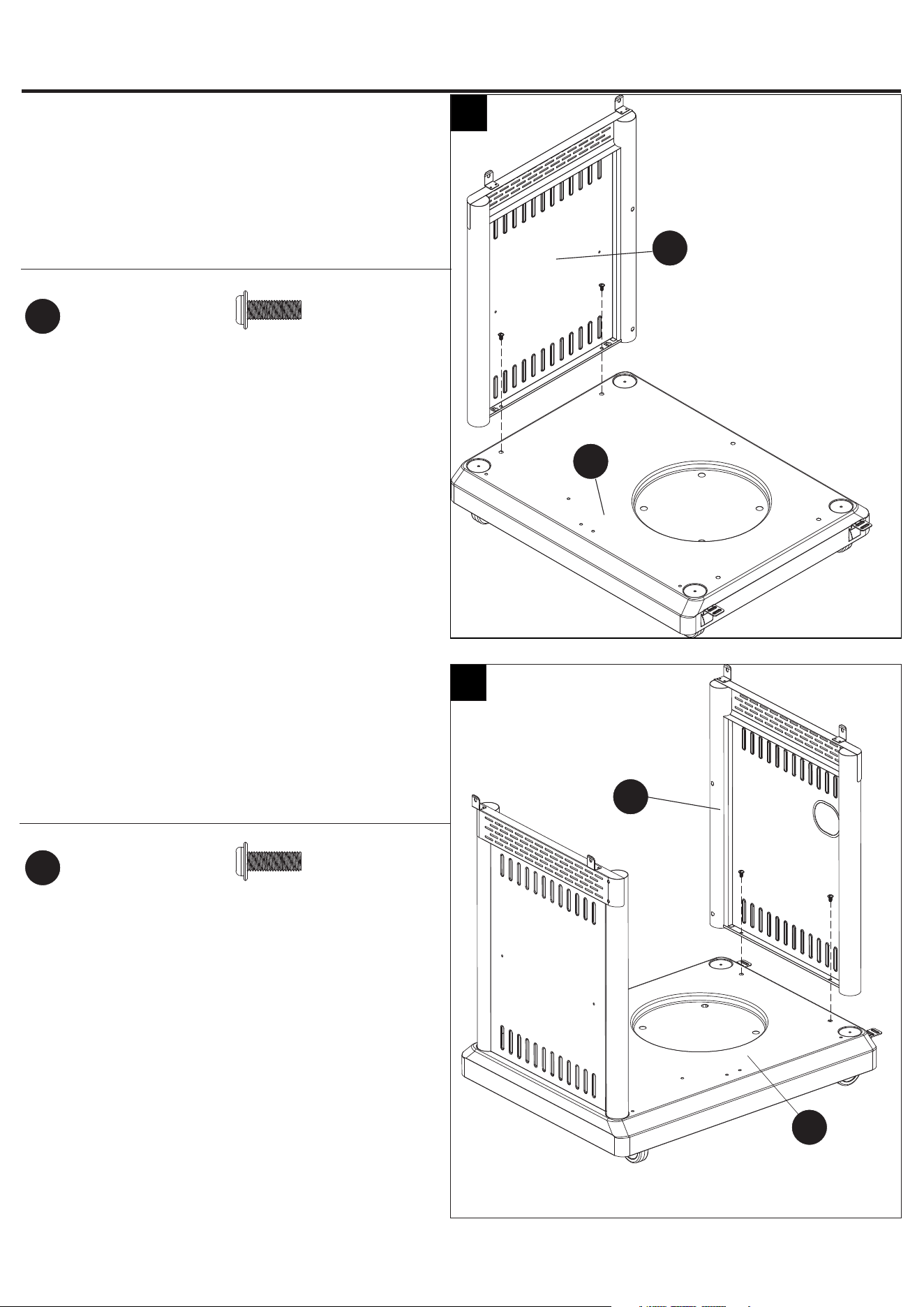
8
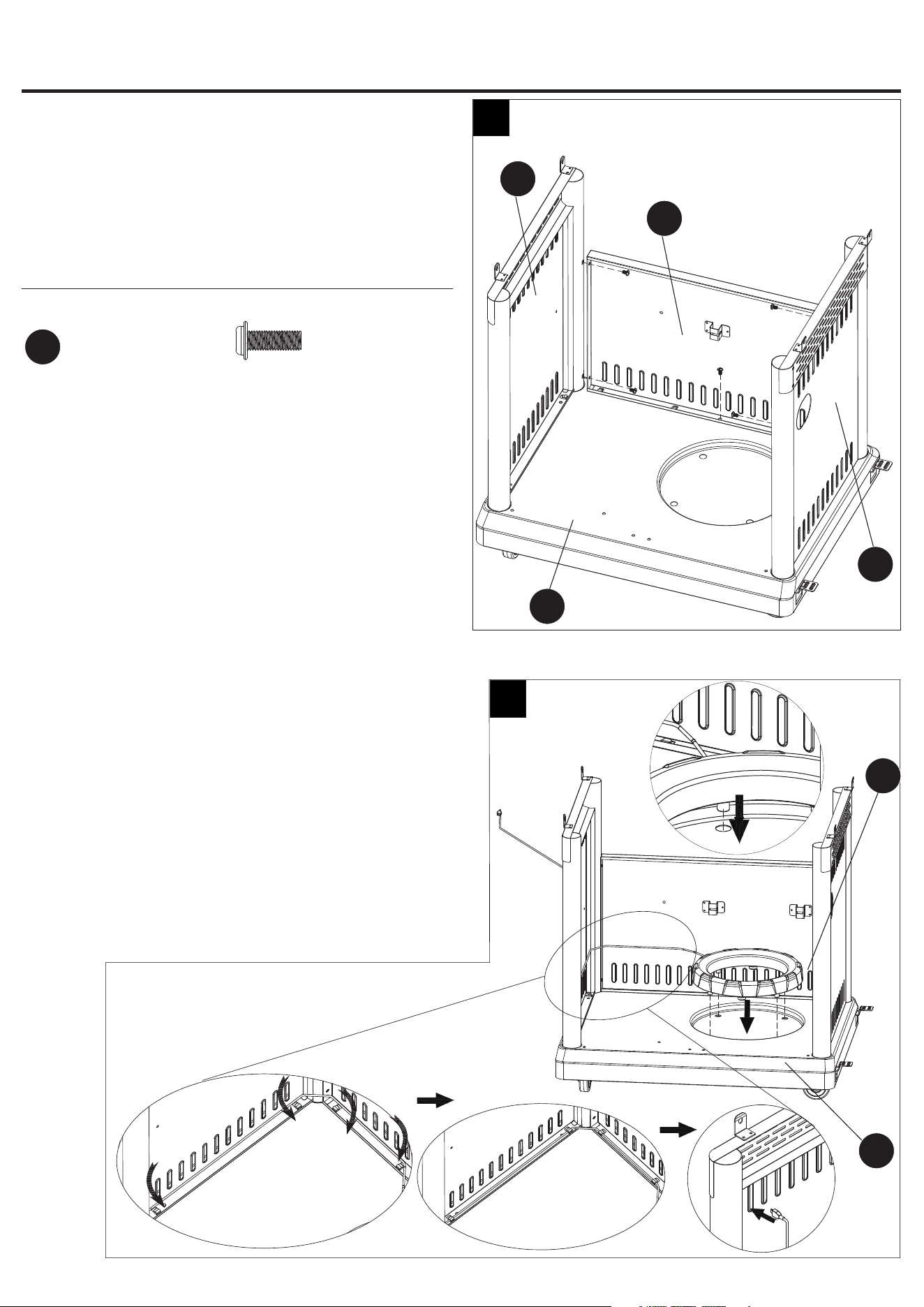
Step 3: Install Left Cart Frame
Align the holes in the left cart frame (U) and bottom panel
(AG). Then insert the M6*16 screw (CC) into the holes
shown in Fig.3. Tighten both screws complelely.
Hardware Used
3
X
Step 4: Install Right Cart Frame
Align the holes in the right cart frame (X) and bottom panel
(AG). Then insert the M6*16 screw (CC) into the holes
shown in Fig.4. Tighten both screws complelely.
Hardware Used
4
AG
ASSEMBLY INSTRUCTIONS
M6x16
Screw
CC
x 2
M6x16
Screw
CC
x 2
AG
U
9
Step 5: Install Back Cart Frame
Align the holes in the back cart frames (Z), left cart frame (U),
right cart frame (X) and bottom panel (AG). Then insert the
M6*16 screw (CC) into the holes shown in Fig.5. Tighten both
screws complelely.
Hardware Used
AG
5
Step 6: Place Propane Tank Scale
Align the pillars on the propane tank scale (AC) and the holes in
the bottom panel (AG). Then place the propane tank scale (AC)
onto the bottom panel (AG).
NOTE:
Make sure all four pillars into the hose so that the weight can be
shown on the digital controller.
Make sure thread the USB connector through the hole in the left
cart frame.
6
AC
Z
ASSEMBLY INSTRUCTIONS
M6x16
Screw
CC
x 5
U
X
AG
10
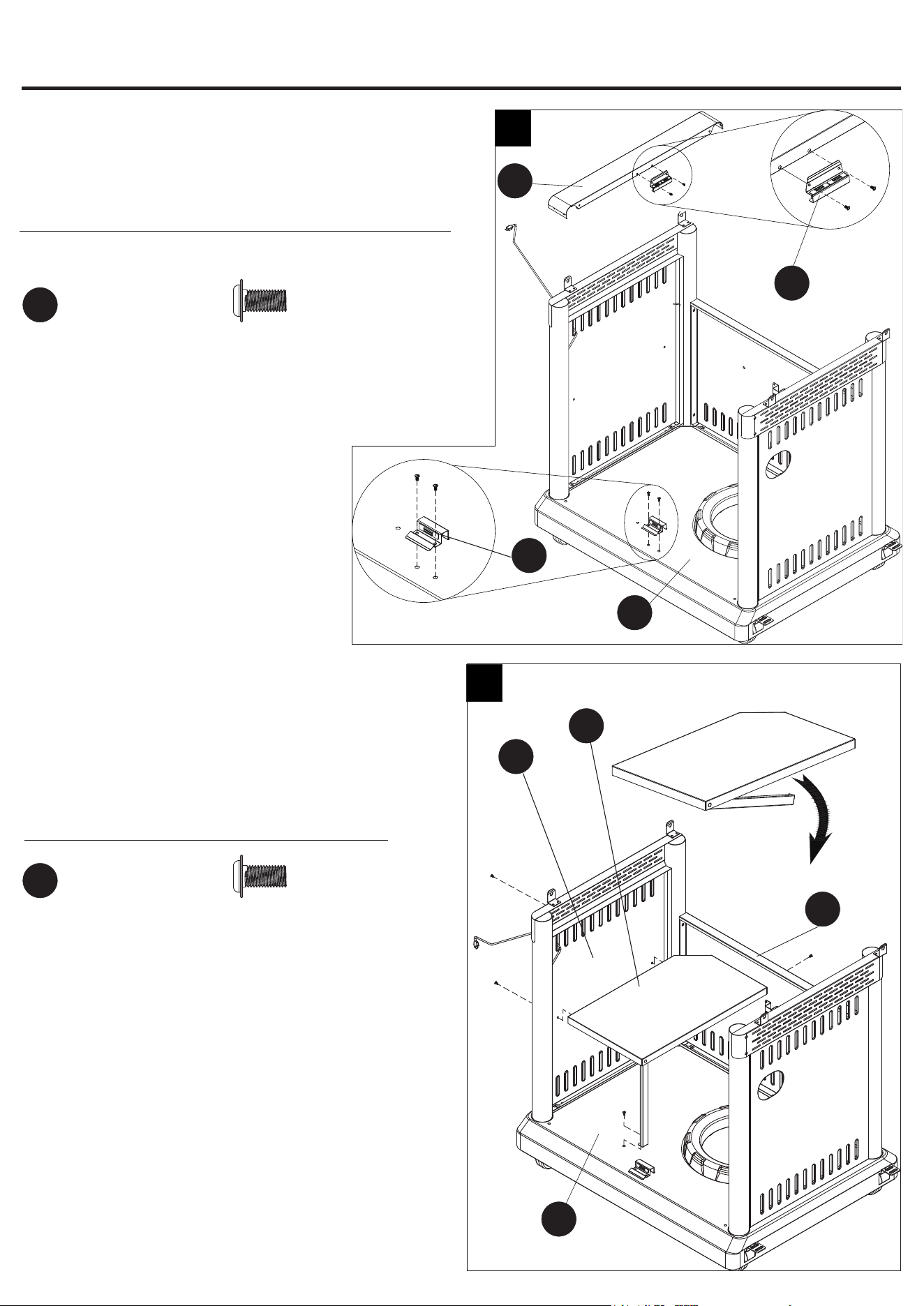
Step 7: Attach Upper and Lower Magnet
Attach the upper magnet (AJ) onto upper front panel (V) and
attach lower magnet (AF) onto the bottom panel (AG).
Hardware Used
7
M4x10
Screw
AA
x 4
Step 8: Attach Center Table
Attach center table (Y) onto the left cart frame (U), back cart
frame (Z) and bottom panel (AG).
NOTE: Unfold the center table support in rst.
Hardware Used
8
Y
AG
Z
ASSEMBLY INSTRUCTIONS
AG
First
U
AF
M4x10
Screw
AA
x 4
AJ
V
11
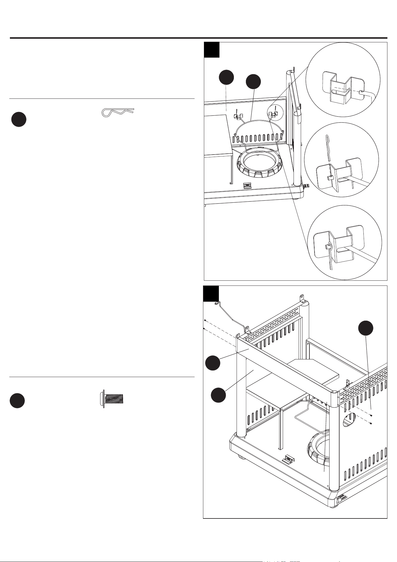
Step 9: Attach LP Gas Tank Retainer Wire
Attach LP Gas Tank Retainer Wire (W) onto the back cart frame
(Z) with two Ø1.4 pins (HH).
Hardware Used
9
Ø1.4
Cotter Pin
HH
x 2
Step 10: Attach Upper Front Panel
Attach the upper front panel (V) with four M4x10 screws (AA).
NOTE: Slide the upper front panel in rst and align the holes in
the left cart frame, right cart frame and upper front panel. Then
insert the four M4x10 screws into the holes shown in Fig.(10).
Hardware Used
10
V
W
U
X
ASSEMBLY INSTRUCTIONS
1
2
3
Z
M4x10
Screw
AA
x 4
12
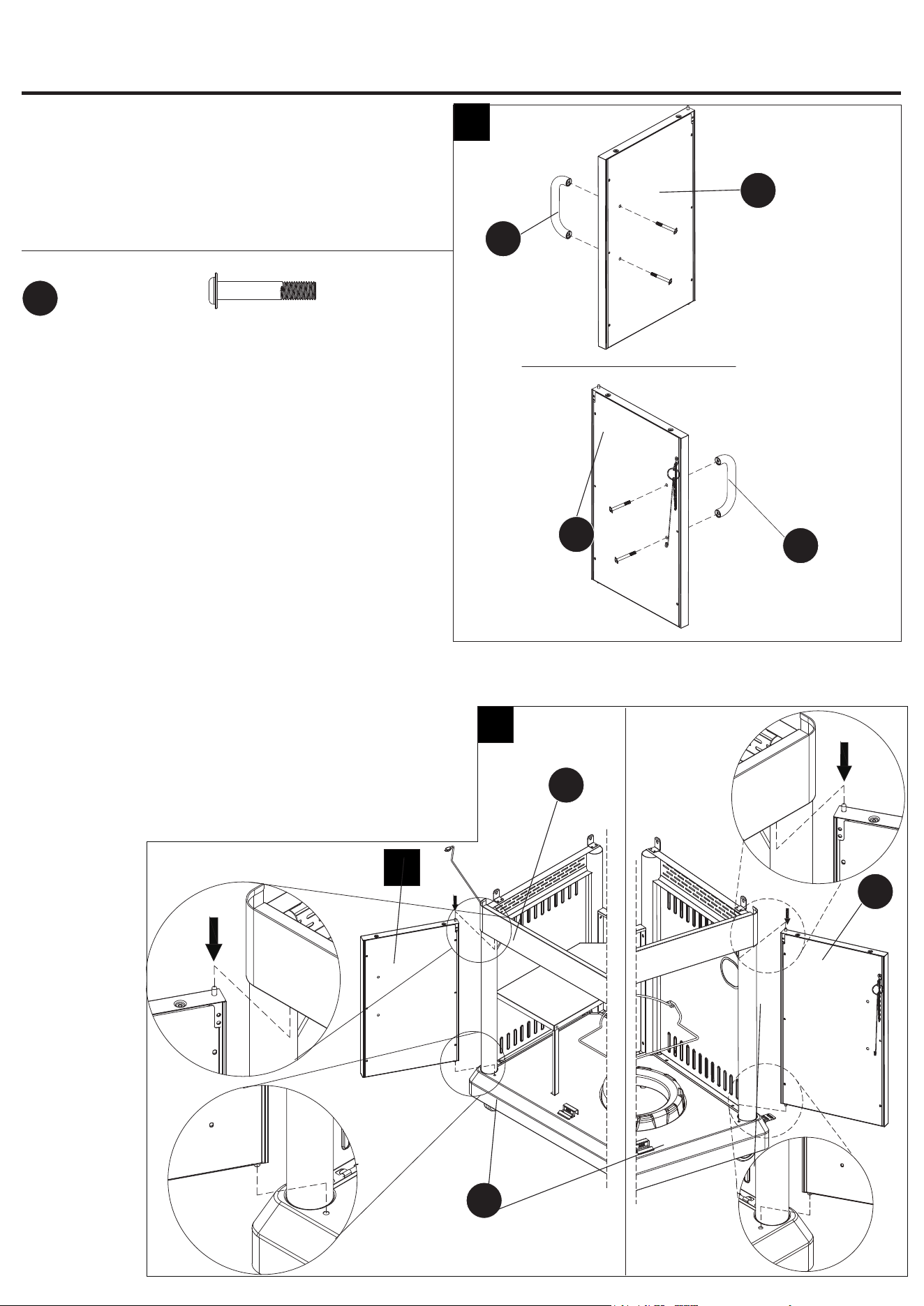
Step 11: Attach Door Handles
Attach the door handles (AA) onto the left door (AB) and right
door (AD).
Hardware Used
11
Step 12: Attach Doors
Put the pillars under the left door (AB) and right door (AD)
into the relevant hole in the bottom panel (AG). Then attach
the doors by pressing the exible axis upward
.
AB
AD
First
Second
12
ASSEMBLY INSTRUCTIONS
AA
AB
AA
M4x35
Screw
BB
x 4
First
Second
AD
V
AG
13
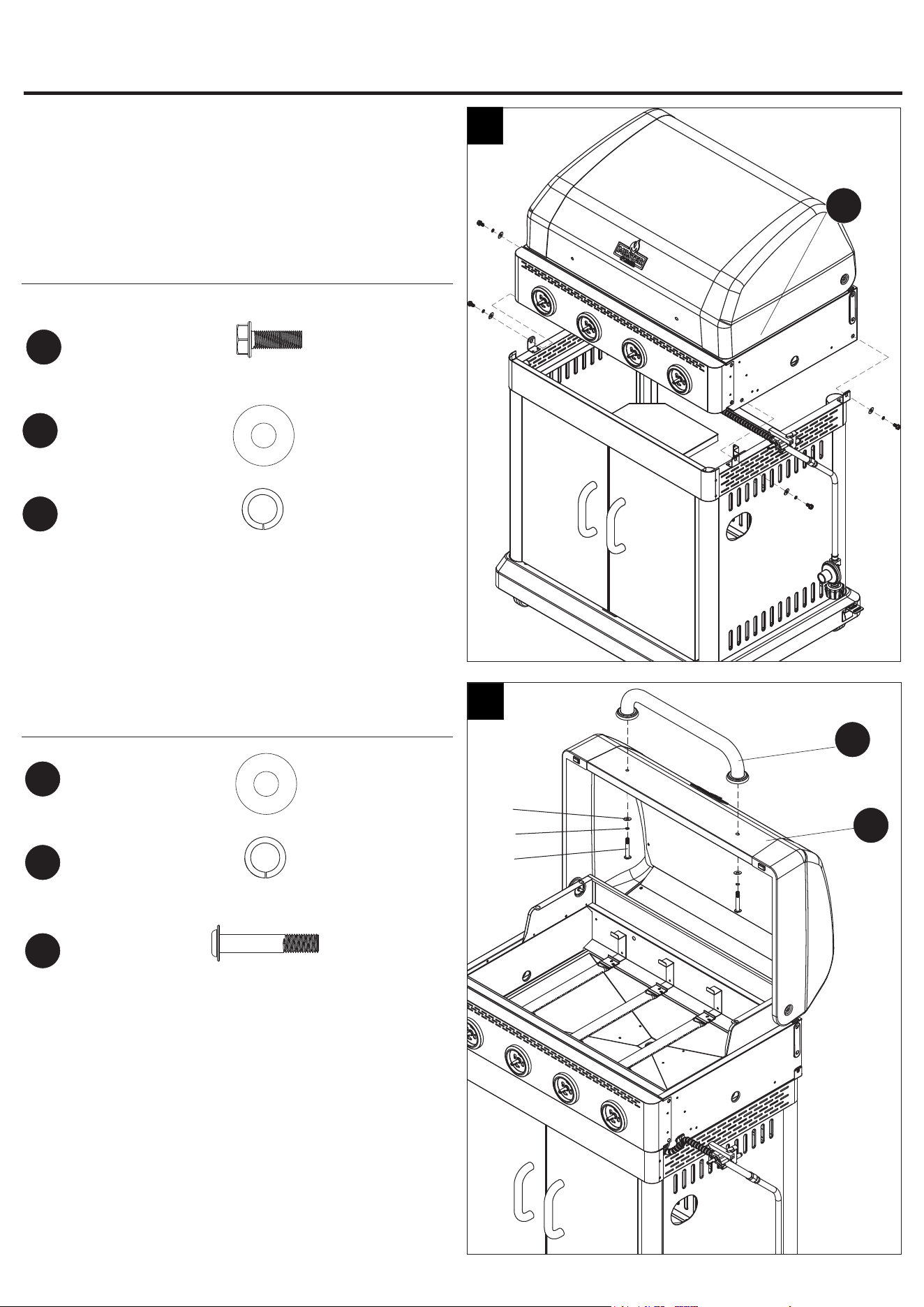
Step 13: Attach Grill Body Assembly
Attach the grill body assembly (G) with four M6x16 screws (DD),
Ø16 washer (FF) and Ø6 lock washer (GG).
NOTE: Two people are needed to perform this step.
Hardware Used
13
G
M6x16
Screw
DD
x 4
Step 14: Attach Lid Handle
Attach the lid handle (D) to the lid (E) with four M6x35 screws (II),
Ø16 washer (FF) and Ø6 lock washer (GG).
Hardware Used
Ø16
Washer
FF
x 4
Ø6
Lock Washer
GG
x 4
ASSEMBLY INSTRUCTIONS
Ø16
Washer
FF
x 2
Ø6
Lock Washer
GG
x 2
M6x35
Screw
II
x 2
D
E
14
14
5 mm
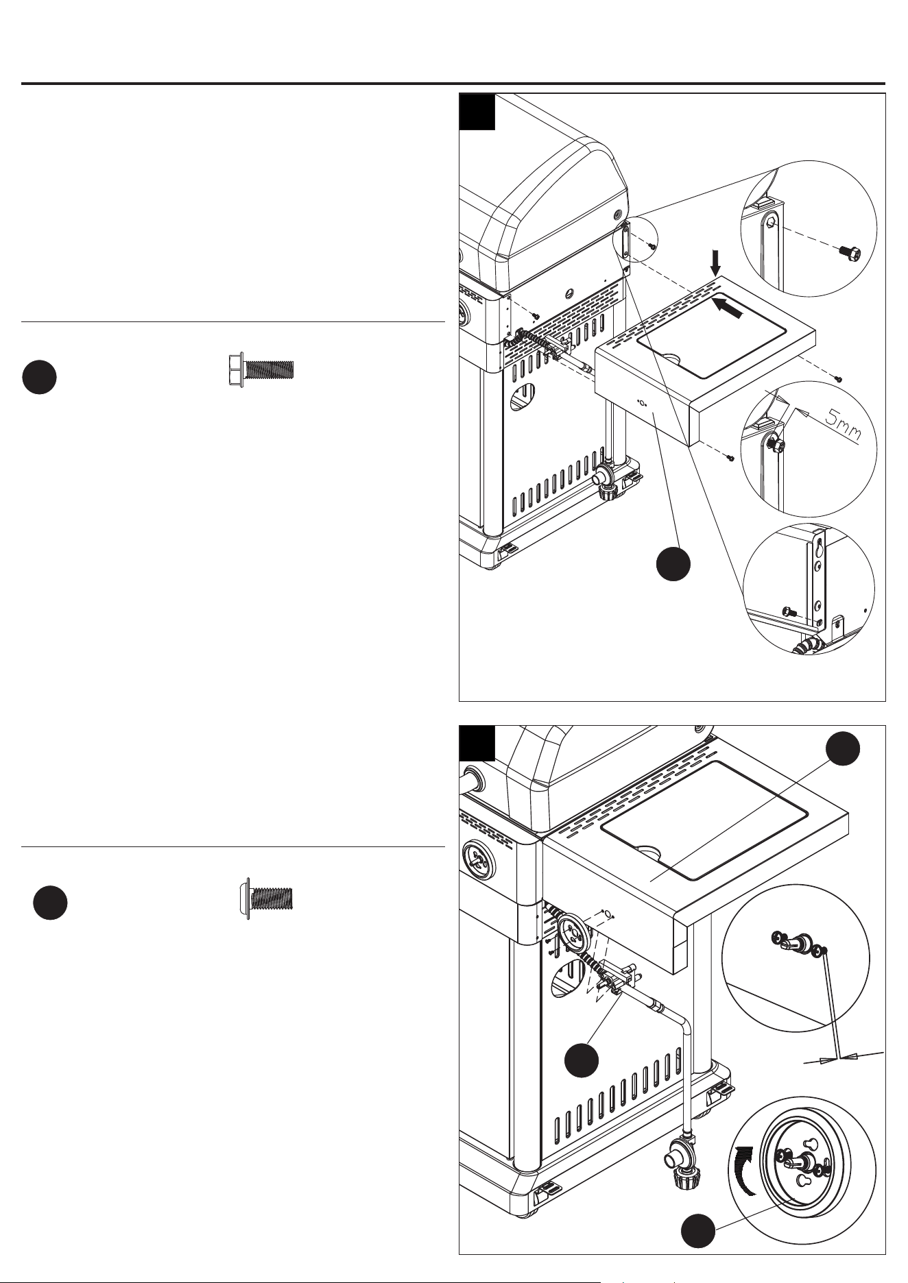
Step 16: Attach Left Side Shelf
Attach the left side shelf(J) with four M6x16 screws (DD)
NOTE: Open the front door of the digital display temperature
controller. Insert two screws into the upper holes with leaving
5 mm threads exposed. Then slide the left side shelf onto
the bolts and insert the other two screws into the lower holes
shown in Fig.16. Tighten all screws completely.
Hardware Used
First
M6x16
Screw
DD
x 4
J
Second
Third Fourth
16
ASSEMBLY INSTRUCTIONS
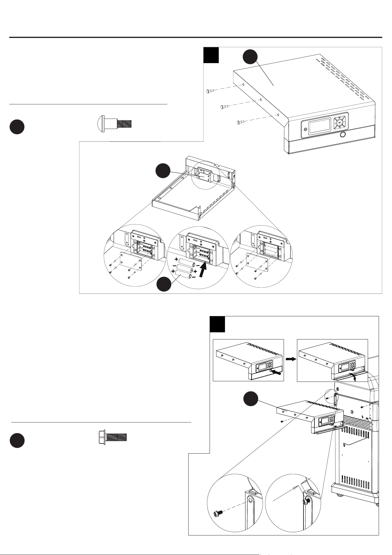
Step 15: Attach Screws and Batteries
Attach the three screws (EE) to the left side shelf (J).
Attach the three AA batteries (AK) into the digital controller (K).
Hardware Used
15
J
M6x22
Screw
EE
x 3
K
First
Second Third
AK
15
Step 17: Attach Right Side Shelf
Attach the right side shelf(Q) with four M6x16 screws (DD)
NOTE: Insert two screws into the upper holes with leaving
5 mm threads exposed. Then slide the right side shelf onto
the bolts and insert the other two screws into the lower holes
shown in Fig.17. Tighten all screws completely.
Hardware Used
Q
17
ASSEMBLY INSTRUCTIONS
M6x16
Screw
DD
x 4
First
Second
Third
Step 18: Install Side Burner Valve and Control Knob Bezel
on Right Side Shelf.
Install the regulator and hose assembly (P) and control knob
bezel (N) with two M4x10 screws (AA)
.
Hardware Used
5mm
18
Q
N
M4x10
Screw
AA
x 2
First
Second
P
16
Step 19: Attach Side Burner
Attach the side burner (S) to the right side shelf (Q) by using
two M4x10 screw (AA).
Hardware Used
19
AA
ASSEMBLY INSTRUCTIONS
First
Third
Second
S
Q
M4x10
Screw
AA
x 2
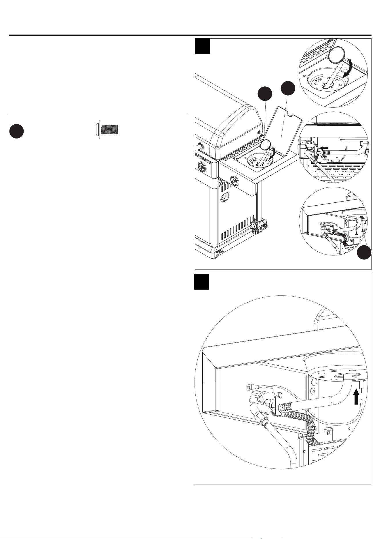
Step 20: Connect Side Burner Ignition Wire
Connect the side burner ignition wire as Fig. (20).
NOTE: Failure to plug the wire to the ignitor electrode will
result in no ignition.
20
17
R
Step 21: Attach Side burner Grid
Put the side burner grid (R) onto the right side shelf (Q) by
aligning the legs with the slots.
21
ASSEMBLY INSTRUCTIONS
Q
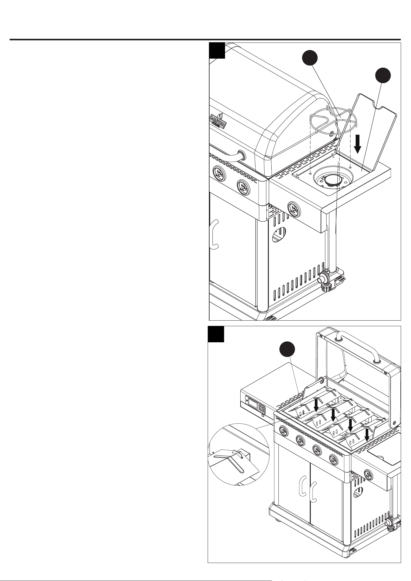
Step 22: Attach Heat Plates
Put the heat plates (C) into place
.
22
C
18
1
2
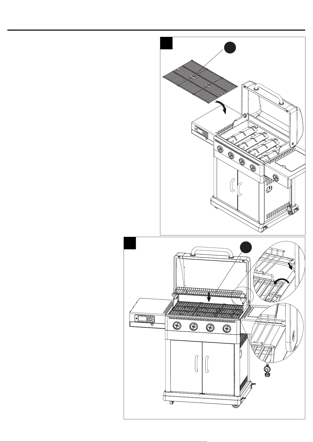
Step 23: Attach Cooking Grid
Put the cooking grids (B) into place.
23
A
B
Step 24: Attach Warming Rack
Put the warming rack (A) into place.
ASSEMBLY INSTRUCTIONS
24
19
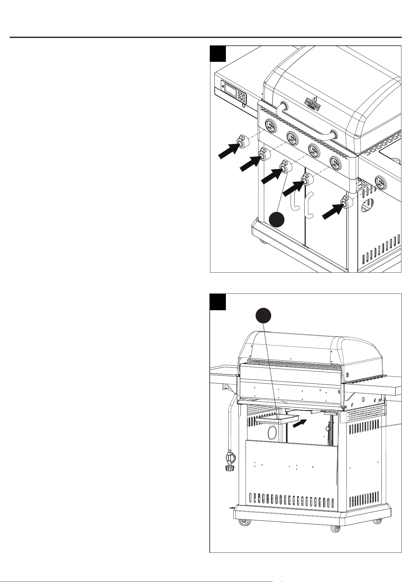
Step 25: Attach Control Knobs
Push ve control knobs (O) onto the stem of the valve.
25
T
Step 26: Attach Grease Cup
Insert the grease cup (T) into the grill body.
26
O
ASSEMBLY INSTRUCTIONS
20
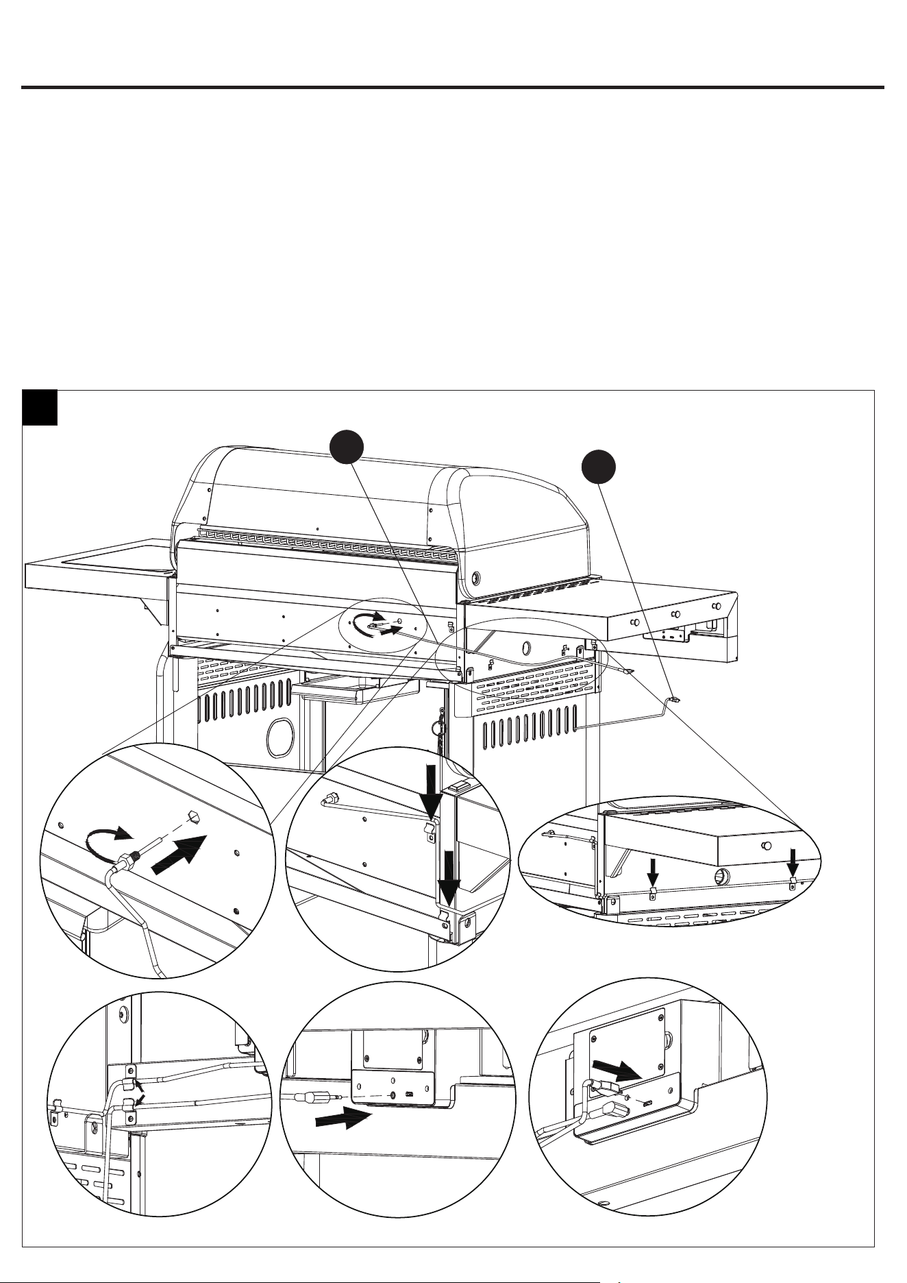
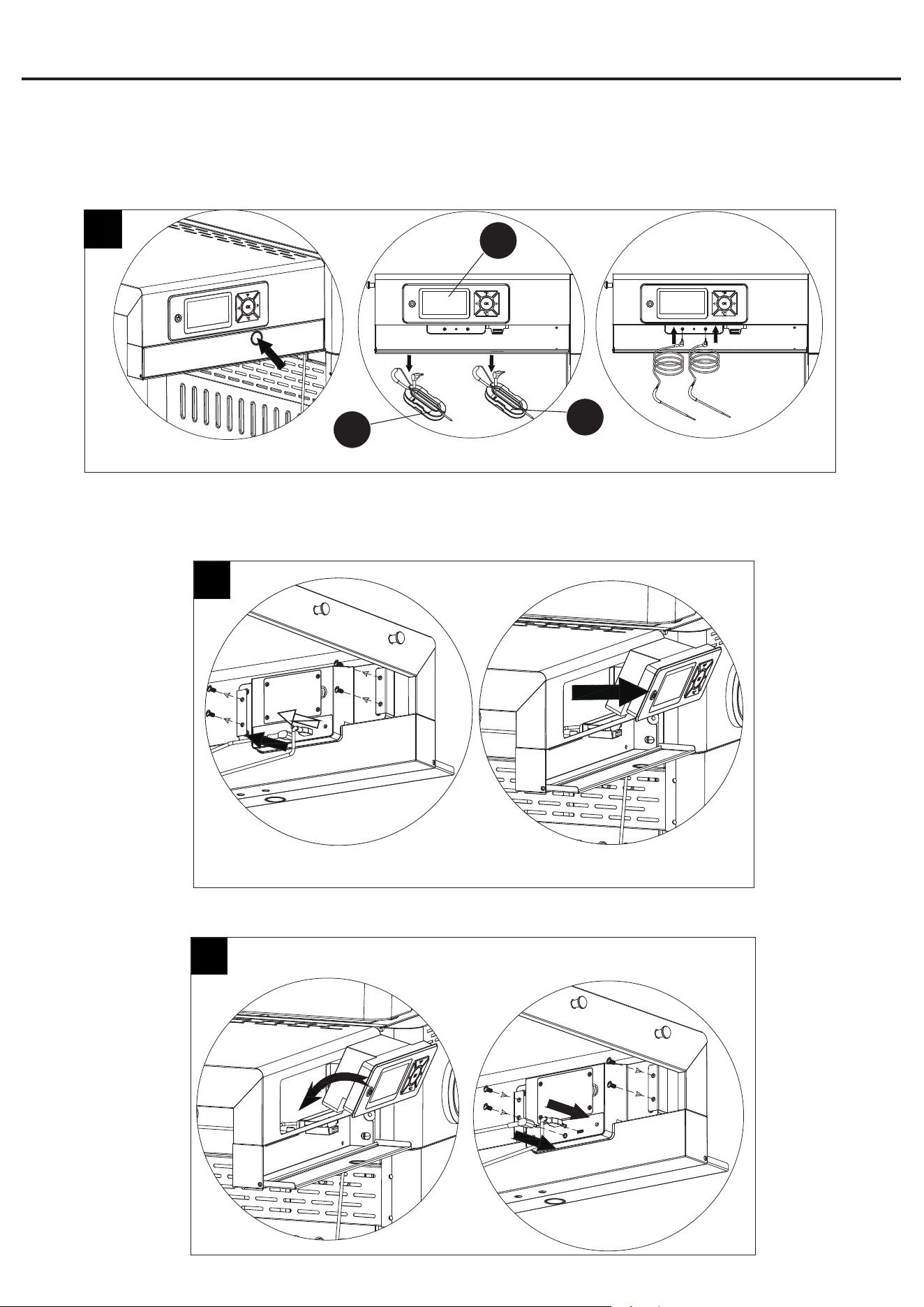
Step 27: Connect Back Ambient Probe and USB
Connector of Propane Tank Scale
Insert the end of back ambient probe into the hole in
the back of grill body. Then insert the front of back
ambient probe and usb connector of propane tank
scale into the digital controller
.
NOTE: Fasten those wires to the buckles shown in
Fig.(27).
27
F
ASSEMBLY INSTRUCTIONS
1
654
32
AC
21
Step 28: Connect Food Probe A and Food Probe B
Press the button on the front box of the digital controller (K) in rst and take out the food probe A (L) and food probe B (M). Then
attach the probes onto the digital controller shown in Fig.28.
P1
P2
P1 P2
28
K
L
M
Step 29: How to Remove Digital Controller Shown in Fig.29
(Note: Remove three probes and USB connector rst.)
30
Step 30: How to Attach Digital Controller Shown in Fig.30
29
ASSEMBLY INSTRUCTIONS
22
INSTALLATION INSTRUCTIONS
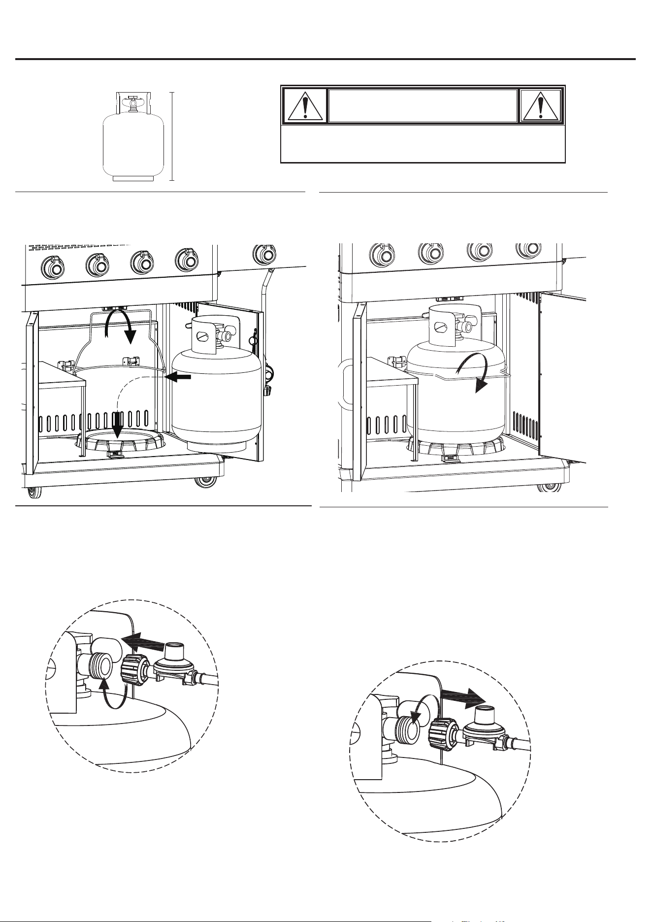
To operate, you will need one precision-filled standard grill LP gas tank with external valve threads.
20 lb
9 Kg
17.9 in. / 45.5 cm
12.2 in. / 31 cm
W LP gas tank must be properly disconnected and
removed prior to moving this grill.
CAUTION
Securing LP Gas Tank
Secure tank by sliding the tank retainer wire over shoulder of LP gas
tank.
Inserting LP Gas Tank
Place precision-filled LP gas tank upright into the notches in the right
cart frame so the tank valve is facing the gas line connection.
Connecting LP Gas Tank
1. Before connecting, be sure there is no debris caught in the head
of the LP gas tank, head of the regulator valve or in the head of
the burner or burner ports.
2. Connect regulator/hose assembly to tank by turning knob
clockwise until it stops.
Disconnecting LP Gas Tank
1. Before disconnecting, make sure the LP gas tank valve is
“CLOSED.”
2. Disconnect regulator/hose assembly from LP gas tank by
turning knob counterclockwise until it is loose.
W CAUTION: LP gas tank must be properly
disconnected and removed prior to moving this
grill.
3. Place the protective cap cover on the LP tank and store the tank
outdoors in a well ventilated area out of direct sunlight.
23
OPERATING INSTRUCTIONS
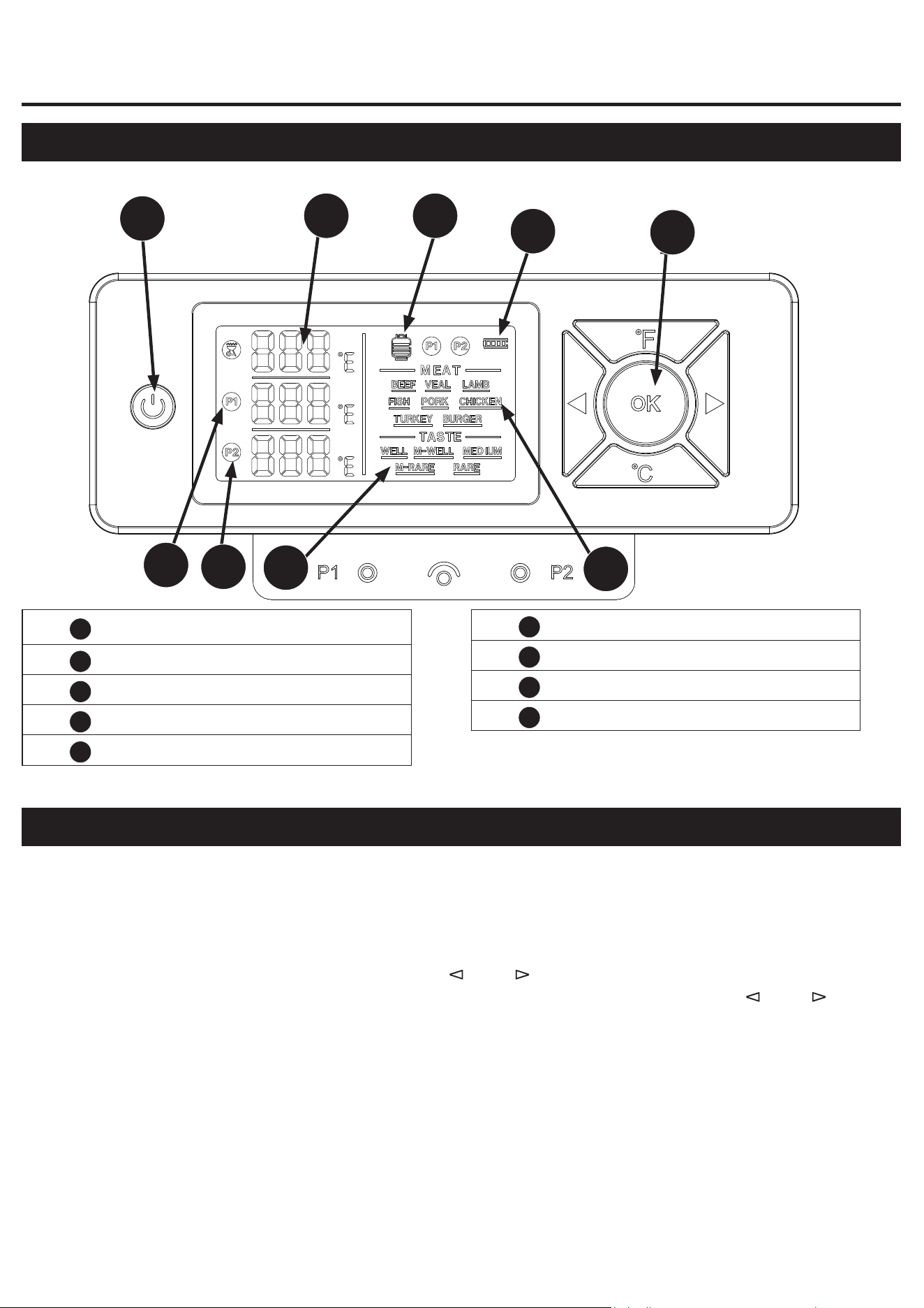
1
Power On /Off
2
Grill Temperature
3
LP Gas Display
4
Battery Level Display
5
Control Dial
6
Type of Food
7
Taste
8
Meat Probe 1 Temperature (P1)
9
Meat Probe 2 Temperature (P2)
Control Board Instruction
1
9
8
7
2 3
4
6
5
Button Instruction
1. Press power button and hold 2 seconds to turn on.
2. Press “˚F/ ˚C ” button once to switch the temperature units between Celsius (ºC) and Fahrenheit (ºF).
3. Press “OK” button once to switch between P1/P2 meat temperature probes.
4. Press “OK” button and hold for 2 seconds to enter the type of food setting. The selected food will blink
and can be adjusted by using the control dial (“ left”/ “ right”/ ”), press “OK” button to enter the taste
setting. The selected taste will blink and can be adjusted by using the control dial (“ left”/ “ right”/ ).
Press “OK” button again to finish the whole setting.
5. Press “OK” button and hold for 2 seconds to restart the setting. Repeat point 3 to point 4 to reset.
Note: P1 and P2 can be used separately. When push the “OK” button it will make a sound with 0.2s.
24
OPERATING INSTRUCTIONS (CONTINUED)
LP gas capacity display for Electronic scale
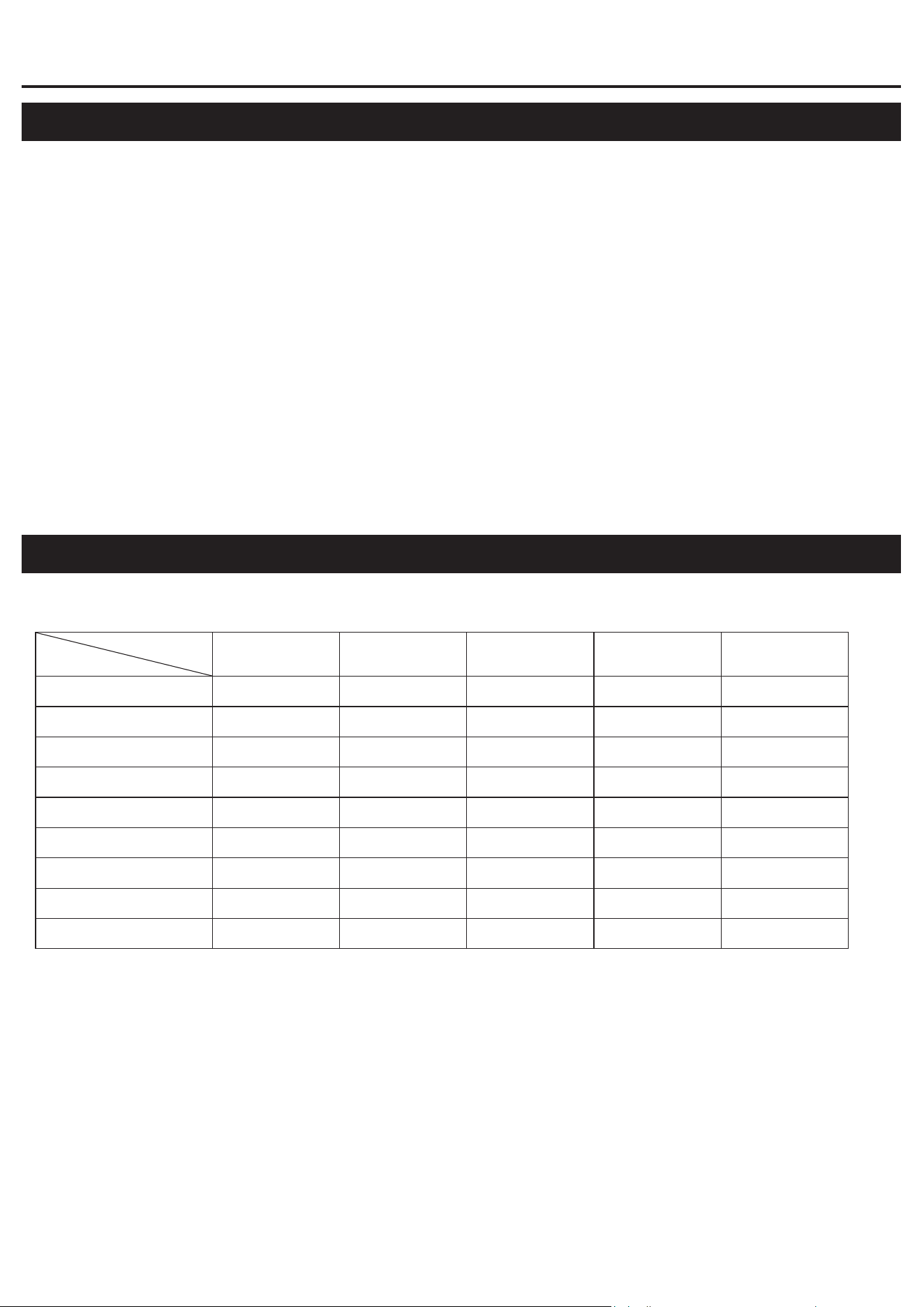
Meat temperature setting
Taste
Meat
RARE M-RARE MEDIUM M-WELL WELL
Temperature Unit °F
Beef 145 °F 151 °F 160 °F 165 °F 171 °F
Veal 151 °F 160 °F 165 °F 171 °F
Lamb 145 °F 151 °F 160 °F 165 °F 171 °F
Fish 145 °F
Pork 160 °F 165 °F 171 °F
Chicken 165 °F
Turkey 165 °F
Burger 165 °F
1. The tank icon with four bars and the tank is full.
2. The tank icon with three bars and the tank is 3/4 full.
3. The tank icon with two bars and the tank is 1/2 full.
4. The tank icon with one bars and the tank is 1/4 full.
We recommend refilling before it gets to 1/4 full or have a full tank near by. Once it gets to 1/4 full, the
tank icon will blink and alarm will sound.
5. Electronic scale will reset when:
• First Use
• The Battery is Replaced
6. If you believe the scale to be inaccurate:
First, remove the tank. Press the up and right button at the same time and hold for 3 seconds. This will
enter the scale reset mode, the icon will blink once the reset is completed. Place the tank back in the grill
and the icon will remain lit with the current reading.
•WARNING: Don’t put any part exceeding 55lb on the tank support, it may cause irreversible damage
to the base sensor, resulting in inaccurate weight and will void the warranty.
Internal meat temperature for different foods and tastes.
1. Once the desired set temperature of your selected meat probe is reached, alarm will sound,
temperature readout will blink and backlight will be activated.
2. Press any control dial to stop the alarm. If the temperature of your selected meat probe continues
to rise at this time, the alarm will no longer sound. Only after the temperature of your selected meat
probe drops below the desired setting, and then the temperature rises to the setting again, the alarm
will sound.
Note: The temperature alarm is different from the LP gas capacity alarm and battery alarm.

25
OPERATING INSTRUCTIONS (CONTINUED)
Battery Capacity
1. When the battery capacity is 76-100% the readout will display four bars.
2. When battery capacity is 51-75%, the readout will display three bars.
3. When battery capacity is 26-50%, the readout will display two bars.
4. When battery capacity is 1-25%, the readout will display one bar.
Note: Once capacity is reached to one bar, the battery icon will blink and alarm will sound.
The backlight introduction
1. The backlight will turn off after 20 seconds. Press any button turn on the backlight again.
2. The backlight will continue to be bright for 20 seconds, and will turn off after 20 seconds.
Protective function
1. When the two probes are not in use, the power will turn off after one minute.
NOTE: Keep the ambient probe plugged in even when not in use.
2. If any of the food probes are plugged in but does not detect any temperature change within 15
minutes, the controller power will turn off.
3. If the ambient probe in the grill body does not detect any temperature change in 3 minutes, it will shut
down automatically.
4. If any probe is not plugged into the hole or open-circuit fault, the readout will display ---. No alarm and
backlight blink.
5. If any probe is in short-circuit fault, the readout will display E0. No alarm and backlight blink.
6. If the USB of the propane tank scale is not plugged or fault, the tank icon and four bars will blink
alternatively.
7. No any action in 1 minute after press power button, it will shut down automatically. No alarm and
backlight blink.
8. No any action in 2 minutes after press power button while fail to confirm the food or taste setting, it
will shut down automatically.
Accessories
1. Requires three AA batteries (included). Checking the batteries periodically and replacing the batteries
before they are fully used to avoid damage to the controller.
2. 3 probes included. One ambient probe and two food probes.
•WARNING: USE ONLY THE PROBES ENCLOSED WITH THIS GRILL. DO NOT USE OTHER
PROBES AS THAT WILL RESULT IN WRONG TEMPERATURE READING AND AVOID WARRANTY.
CALL OUR CUSTOMER SERVICE DEPARTMENT AT 1.800.963.0211 WITH QUESTIONS.
26
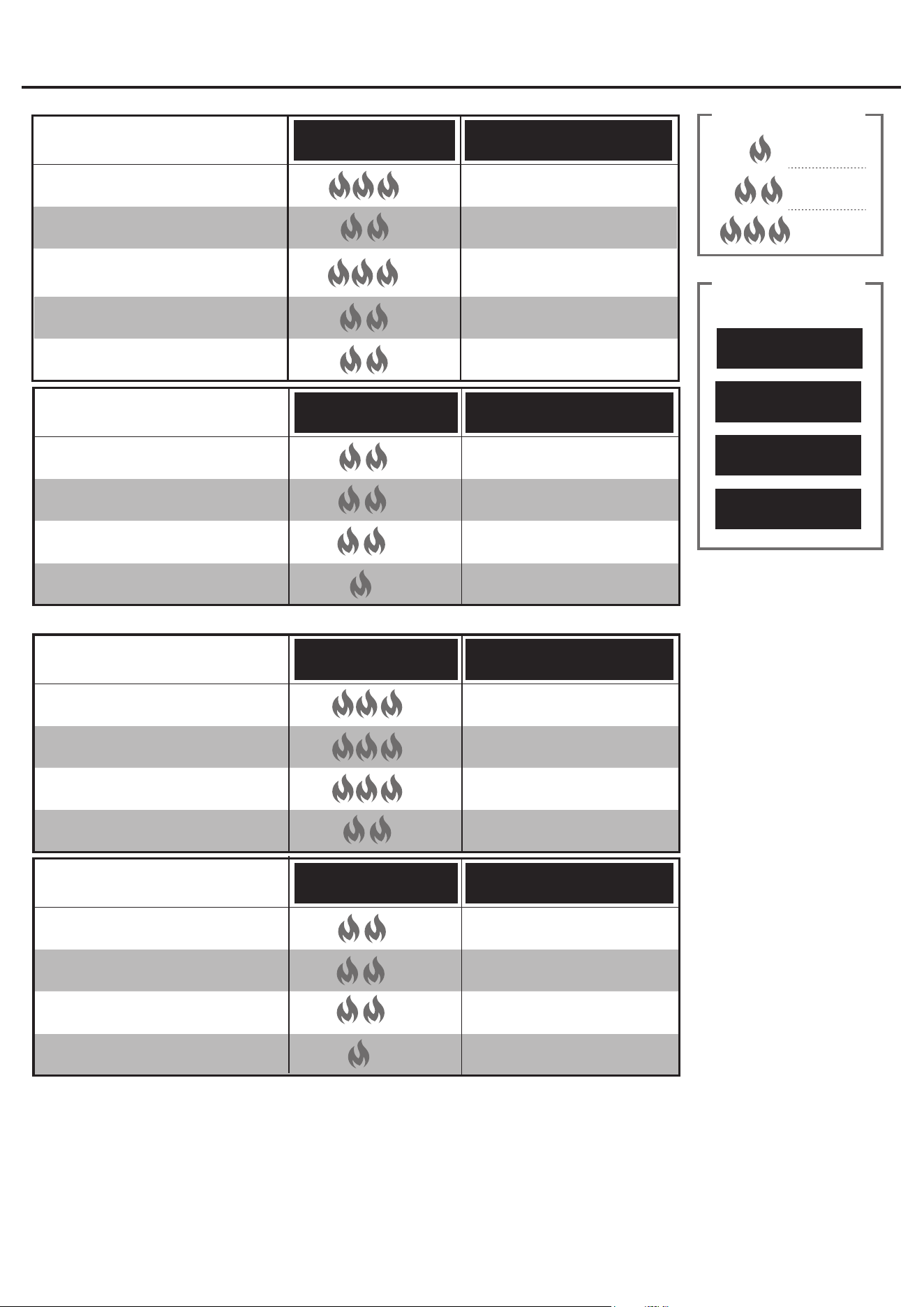
OPERATING INSTRUCTIONS (CONTINUED)
AVG. COOKING TIMEHEAT LEVEL
SEAFOOD
LARGE
SHRIMP
4-6 MIN.
1 1/2 OUNCES
SCALLOP
4-6 MIN.
1-INCH THICK
FISH, FILET
5-10 MIN.
1 POUND
FISH, WHOLE
15-20 MIN.
AVG. COOKING TIMEHEAT LEVEL
CHICKEN
4 OUNCES - BONELESS, SKINLESS
CHICKEN BREAST OR THIGH
8-12 MIN.
3-6 OUNCES - BONE-IN*
CHICKEN THIGH OR LEG
35-45 MIN.
10-12 OUNCES - BONE-IN*
CHICKEN BREAST
35-45 MIN.
8 POUNDS
WHOLE CHICKEN*
3-5 HOURS
AVG. COOKING TIMEHEAT LEVEL
BEEF
1-INCH THICK - FILET MIGNON, RIBEYE,
NEW YORK STRIP & PORTERHOUSE
STEAK, MEDIUM
6-8 MIN.
1-INCH THICK
SKIRT STEAK, MEDIUM
4-6 MIN.
3/4 - INCH THICK
BURGER
8-10 MIN.
4 OUNCES
HOT DOG
5-7 MIN.
1-INCH THICK
HANGER STEAK, MEDIUM
8-10 MIN.
*BONE-IN CHICKEN SHOULD INITIALLY BE COOKED OR “BROWNED” OVER DIRECT HEAT FOR SEVERAL MINUTES BEFORE BEING TRANSFERRED TO INDIRECT HEAT.
USDA SAFE MINIMAL
INTERNAL TEMPS
145°F
FISH & SHELLFISH:
160°F
GROUND BEEF OR PORK:
165°F
CHICKEN:
BEEF OR PORK STEAKS
OR CHOPS:
145°F
LOW HEAT
150°-250°F
MEDIUM HEAT
300°-450°F
HIGH HEAT
450°-550°F+
HEAT KEY
AVG. COOKING TIMEHEAT LEVEL
PORK
1-INCH THICK
PORK CHOP, MEDIUM
8-10 MIN.
8 POUNDS
PORK SHOULDER/BUTT
12 HOURS
3-OUNCE LINK
SAUSAGE
10-13 MIN.
1 POUND
PORK TENDERLOIN
15-20 MIN.
APPROX. 90 MIN / LB.
27
Checking for Leaks
Burner Connections
1. Make sure the regulator hose and valve connections are securely fastened to the burner
and the tank.
2. Visually check the connection between the burner/venturi tube and orifice.
3. Make sure the burner/venturi tube fits over the orifice.
W WARNING: Failure to inspect this connection or follow these
instructions could cause a fire or an explosion which can cause death,
serious bodily injury or damage to property.
4. Please refer to diagram for proper installation (Figures 1 and 3).
5. If the burner/venturi tube does not rest flush to the orifice, as shown.
Tank/Gas Line Connection
1. Make 2-3 oz. of leak detection solution by mixing one part liquid dishwashing soap with
three parts water.
2. Make sure control knobs are in the “ OFF” position (Figure 3).
3. Connect LP gas tank per “Installing LP Gas Tank” section.
4. Turn LP gas tank valve to “OPEN.”
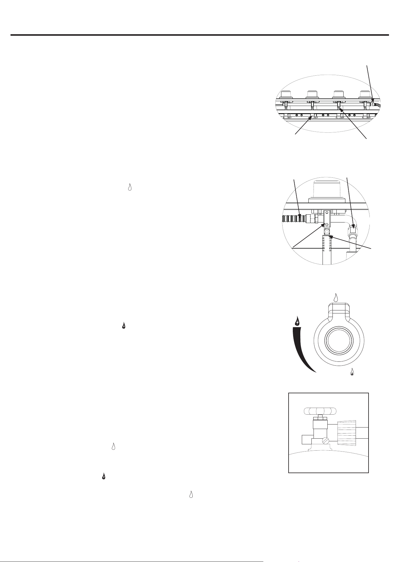
5. Spoon several drops of solution, or use a squirt bottle, at all “X” locations (Figures 1, 2 and
4).
a. If any bubbles appear, turn LP gas tank valve to “CLOSED,” reconnect and re-test.
b. If you continue to see bubbles after several attempts, turn LP gas tank valve to
“CLOSED” and disconnect LP gas tank, per “Disconnecting LP Gas Tank” section.
c. If no bubbles appear after one minute, turn LP gas tank valve to “CLOSED,” wipe away
solution and proceed.
Operating Main Burners
First Use
1. Make sure all labels, packaging and protective films have been removed from the grill.
2. Remove manufacturing oils before cooking on this grill for the first time by operating
the grill for at least 15 minutes on
(HIGH) with the lid closed. This will “heat clean” the
internal parts and dissipate odors.
Lighting
W CAUTION: Keep outdoor gas cooking appliance area clear and free from
combustible materials, gasoline and other flammable vapors and liquids.
W CAUTION: Do NOT obstruct the flow of combustion and ventilation air.
W CAUTION: Check and clean burner/venturi tubes for insects and insect
nests. A clogged tube can lead to a fire.
W CAUTION: Attempting to light the burner with the lid closed may cause an
explosion.
1. Open lid.
2. Check for obstructions of airflow to the burners. Spiders, insects and webs can clog the burner/
venturi tube. A clogged burner tube can lead to a fire.
3. All control knobs must be in the “ OFF” position (Figure 3).
4. Connect LP gas tank per “Connecting LP Gas Tank” section.
5. Turn LP gas tank valve to “OPEN.”
6. Push and turn control knob to
(HIGH). the burner should light. If it does not, repeat up to three
times.
7. If ignition does not occur in 5 seconds, turn burner control knob “ OFF,” wait 5 minutes, and repeat lighting procedure.
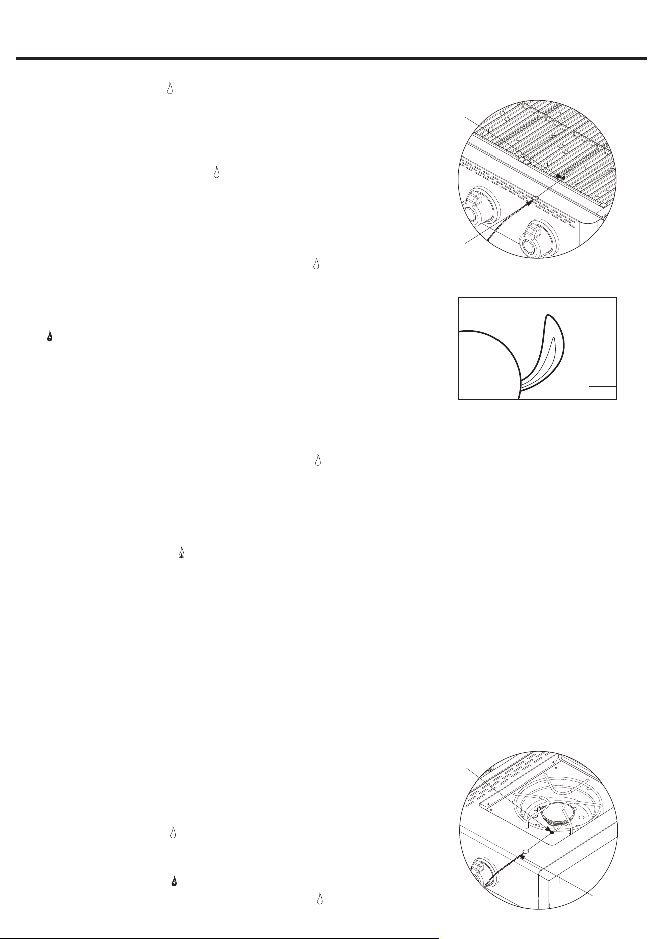
8. If igniter does not light burner, use a lit match secured with the lighting rod (included with grill) to light burners. Access the burners
through the cooking grid and heat plates. Position lit match near side of burner (Figure 5).
Important: Always use the lighting rod (included) when lighting burners with a match.
9. After lighting, observe the burner flame. Make sure all burner ports are lit and flame height matches illustration (Figure 6).
Note: Each burner lights independently - repeat steps 5-9 for the other burners.
OPERATING INSTRUCTIONS (CONTINUED)
Figure 1 Main Burners
X
Burner/
Venturi Tube
LP Gas Valve
with Orifice
LP Gas
Connection
Figure 2 Side Burner
X
X
LP Gas
Connection
Valve Soft Pipe
Connection
LP Gas Valve
with Orifice
Burner/
Venturi
Tube
Figure 3
OFF
Figure 4
X
X
X
X
X
28
Operating Side Burner
NOTE: Side burner can be used while main burners are operating.
Never use side burner as a grill.
W CAUTION: Maximum weight for side burner and side shelf is 33 lbs.
W CAUTION: Using pots larger than 6 quarts in capacity could exceed weight limit of the side burner shelf,
resulting in failure of grill cart components.
W CAUTION: Do NOT lean on the side burner shelf.
W CAUTION: Attempting to light the burner with the lid closed may cause an
explosion.
Lighting
1. Open lid.
2. Check for obstructions of airflow to the burners. Spiders, insects and webs can clog the burner/
venturi tube. A clogged burner tube can lead to a fire.
3. Control knob must be in the “ OFF” position (Figure 3).
4. Connect LP gas tank per “Installing LP Gas Tank” section.
5. Turn LP gas tank valve to “OPEN.”
6. Push and turn control knob to
(HIGH). The burner should light. If not, repeat up to three times.
7. If ignition does not occur in 5 seconds, turn burner control knob “ OFF,” wait 5 minutes and
repeat lighting procedure.
Figure 5
Lighting
hook
Match
Figure 6
Burner
Flame
Slight
Yellow
Slight
Blue
Dark
Blue
Figure 7
Lighting
Hook
Match
W CAUTION: If burner flame goes out during operation, immediately turn the
control knobs to the “ OFF” position, LP gas tank valve “CLOSED” and
open lid to let the gas clear for 5 minutes before re-lighting.
Turning Off
1. Turn LP gas tank valve to “CLOSED.”
2. Turn all control knobs clockwise to the “ OFF” position.
Note: A “poof” sound is normal as the last of the LP gas is burned.
3. Disconnect LP gas tank per “Disconnecting LP Gas Tank” section.
Controlling Flare-ups
W CAUTION: Putting out grease fires by only closing the lid is not possible.
1. If a grease fire develops, turn control knobs to the “ OFF” position and LP
gas tank valve “CLOSED.” Do NOT use water on a grease fire. This can
cause the grease to splatter and could result in serious burns, bodily harm
or other damage.
2. Do NOT leave grill unattended while preheating or burning off food residue on
(HIGH). If grill has not been cleaned, a grease fire can occur.
W WARNING: When cooking, fire extinguishing materials should be readily
accessible. In the event of an oil/grease fire, use type BC dry chemical fire
extinguisher or smother with dirt, sand or baking soda. Do NOT attempt to
extinguish with water.
Flare-ups are a part of cooking meats on a grill and add to the unique flavor of grilling.
Excessive flare-ups can over-cook your food and be dangerous.
Important: Excessive flare-ups result from the build-up of grease in the bottom of your grill.
If a grease fire occurs, close the lid AND turn the control knob(s) to “ OFF” until the grease burns out.
Be careful when opening the lid as sudden flare-ups may occur.
If excessive flare-ups occur, do NOT pour water onto the flames.
Minimize Flare-ups:
1. Trim excess fat from meats prior to cooking.
2. Cook high fat content meats on
(LOW) setting or indirectly.
3. Ensure that your grill is on a hard, level, non-combustible surface and the grease is allowed to
drain into grease receptacle.
OPERATING INSTRUCTIONS (CONTINUED)

29
W CAUTION: If burner flame goes out during operation, immediately turn the control knob to the “ OFF”
position and LP gas tank valve “CLOSED” and open lid to let the gas clear for 5 minutes before re-lighting.
Turning Off
1. Turn LP gas tank valve to “CLOSED.”
2. Turn control knob clockwise to the “ OFF” position.
Note: A “poof” sound is normal as the last of the LP gas is burned.
3. Disconnect LP gas tank per “Disconnecting LP Gas Tank” section.
Cooking
1. Open lid and ignite the side burner per “Lighting” instructions.
2. Adjust control knob to desired flame height.
3. Place pan on center of grid.
4. Cook and adjust temperature as needed.
5. Turn grill off per “Turning Off” instructions.
W CAUTION:
1. All cleaning and maintenance should be done when grill is cool and with the fuel supply disconnected.
2. Do NOT clean any grill part in a self-cleaning oven. The extreme heat will damage the finish.
3. Do NOT enlarge valve orifices or burner ports when cleaning the valves or burners.
Notices
1. This grill should be thoroughly cleaned and inspected on a regular basis.
2. Abrasive cleaners will damage this product.
3. Never use oven cleaner to clean any part of grill.
Before Each Use:
1. Keep the grill area clean and free from any combustible materials, gasoline, and other flammable vapors and liquids.
2. Do NOT obstruct the flow of the combustion of LP gas and the ventilation of air.
3. Keep the ventilation opening(s) of the LP gas tank area free and clear from debris.
4. Visually check the burner flames to make sure your grill is working properly (Figure 8).
5. See sections below for proper cleaning instructions.
6. Check for obstructions of airflow to the burners. Spiders, insects and webs can clog the burner/venturi tube. A clogged burner tube can
lead to a fire.
Cleaning Surfaces
1. Wipe surfaces clean with mild dishwashing detergent or baking soda mixed with water.
2. For stubborn surfaces, use a citrus-based degreaser and a nylon scrubbing brush.
3. Rinse clean with water.
4. Allow to air dry.
Cleaning Main Burners
1. Turn LP gas tank valve to “CLOSED.”
2. Turn all control knobs clockwise to the “ OFF” position.
Note: A “poof” sound is normal as the last of the gas is burned.
3. Disconnect LP gas tank per “Disconnecting LP Gas Tank” section.
4. Remove cooking grids and heat plates.
1. If igniter does not light burner, use a lit match secured with the lighting rod (included with grill) to light burners. Position the lit match near
side of the burner (Figure 7).
2. Important: Always use the lighting rod (included) when lighting burner with a match. After lighting, observe the burner flame. Make sure all
burner ports are lit and flame height matches illustration (Figure 6).
OPERATING INSTRUCTIONS (CONTINUED)
CARE AND MAINTENANCE
30
1. Remove burners by removing the fasteners, which secure the burners to the grill bottom.
2. Lift burners up and away from gas valve orifice.
3. Disconnect wire from spark electrode.
4. Clean venturi of each burner with small bottle brush or compressed air.
5. Remove all food residue and dirt from burner surface.
6. Clean any clogged ports with a stiff wire (such as an opened paper clip).
7. Inspect burners for any damage (cracks or holes). If damage is found, replace with new
burner(s) from manufacturer.
8. Re-install burner(s). Checking to insure that gas valve orifice is correctly positioned inside
each burner/venturi tube. Also, check position of spark electrode.
9. Replace heat plate(s) and cooking grid(s).
10. Connect LP gas tank per “Installing LP Gas Tank” section.
11. Perform leak test per “Checking for Leaks” section.
Cleaning Side Burner
1. Turn LP gas tank valve to “CLOSED.”
2. Turn all control knobs clockwise to the “ OFF” position.
Note: A “poof” sound is normal as the last of the gas is burned.
3. Disconnect LP gas tank per “Disconnecting LP Gas Tank” section.
4. Remove side burner grid.
5. Remove burner by removing the screws that secure the burner to the side shelf.
6. Lift burner up and away from gas valve orifice.
7. Clean venturi of burner with small bottle brush or compressed air.
8. Remove all food residue and dirt from burner surface.
9. Clean any clogged ports with a stiff wire (such as an opened paper clip).
10. Inspect burner for any damage (cracks or holes). If damage is found, replace with new
burner from manufacturer.
11. Re-install burner(s). Checking to insure that gas valve orifice is correctly positioned
inside each burner/venturi tube. Also, check position of spark electrode.
12. Replace cooking grid(s).
13. Connect LP gas tank per “Installing LP Gas Tank” section.
14. Perform leak test per “Checking for Leaks” section.
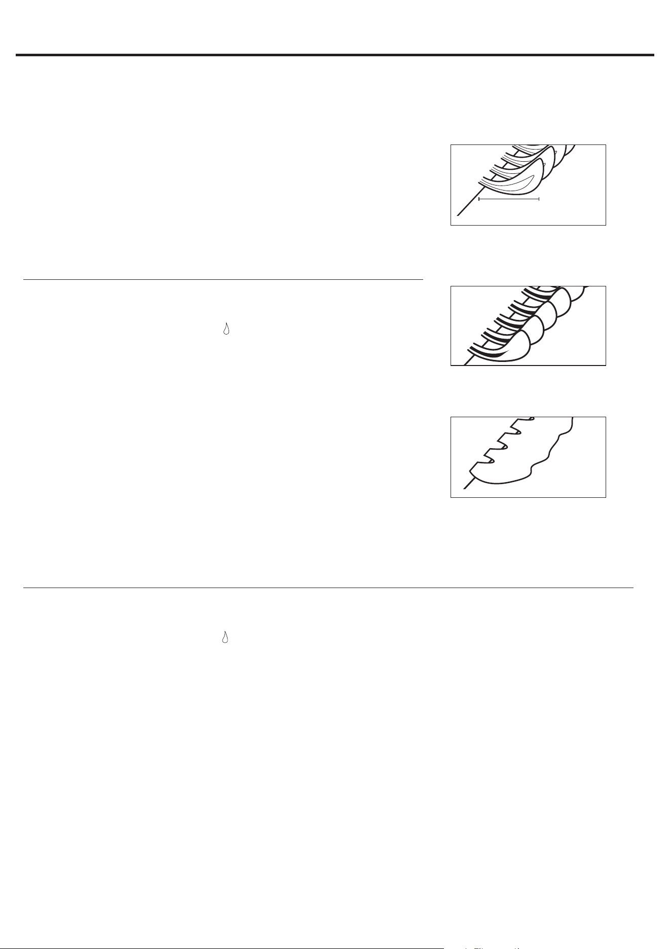
Figure 8
Burner Flame Conditions
Use this chart to see if your burners need to be
cleaned.
1-2 in. /
25.4 - 50.8 mm
Normal: Soft blue flames with yellow
tips between 1 in. - 2 in. height.
Needs cleaning: Noisy with hard
blue flames.
Has to be replaced: Wavy with
yellow flames.
Before Storing
1. Turn LP gas tank valve to “CLOSED.”
2. Turn all control knobs clockwise to the “ OFF” position.
Note: A “poof” sound is normal as the last of the gas is burned.
3. Disconnect LP gas tank per “Disconnecting LP Gas Tank” section.
4. Clean all surfaces.
5. Lightly coat the burner(s) and cooking grid(s) with cooking oil to prevent excess rusting.
6. If storing the grill indoors, disconnect the LP tank per “Disconnecting LP Gas Tank” section.
7. Place the protective cap cover on the LP tank and store the tank outdoors in a well-ventilated area out of direct sunlight.
8. If storing the grill indoors, cover the grill and store in a cool dry place.
9. If storing the grill outdoors, cover the grill with a grill cover for protection from the weather.
CARE AND MAINTENANCE (CONTINUED)

31
LIMITED WARRANTY
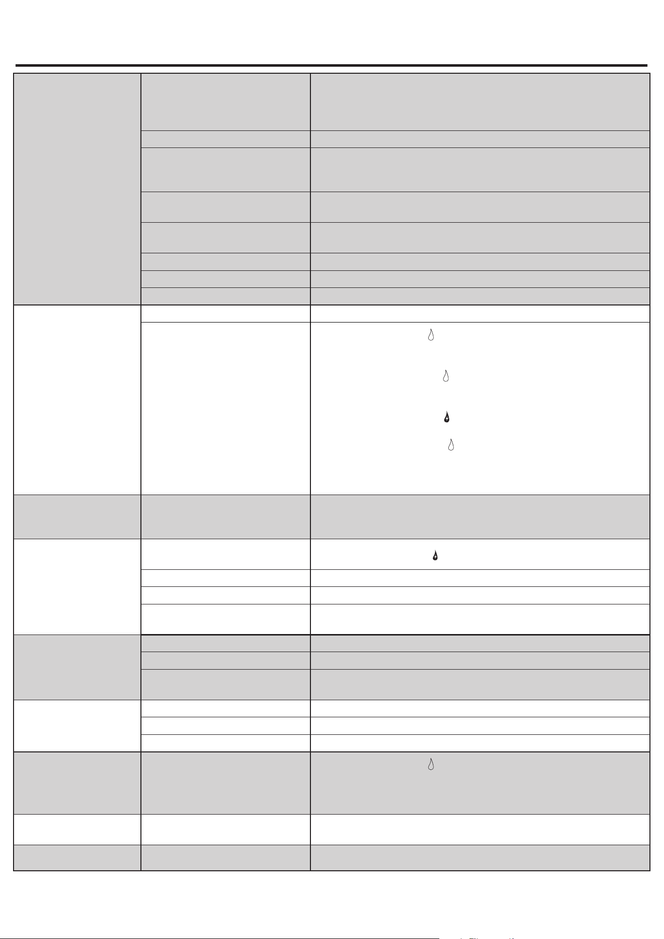
TROUBLESHOOTING
Problem Possible Cause Prevention/Cure
Burner will not light using
igniter
LP gas tank valve is closed
Make sure regulator is securely attached to the LP gas tank per “Installing LP
Gas Tank,” then turn LP gas tank valve to “OPEN”
LP gas tank is low or empty Exchange, refill or replace LP gas tank
LP gas
1. Turn LP gas tank valve to “CLOSED”
2. Wait 5 minutes for gas to clear
3. Follow “Checking for Leaks” section
Wires or electrode covered with
cooking residue
Clean wire and/or electrode with rubbing alcohol
Electrode and burners are wet Wipe dry with cloth
Electrode cracked/broken - sparks at
crack
Replacement part(s) may be needed - contact Customer Care at
1.800.963.0211
Wire loose or disconnected
Reconnect wire or replacement part(s) may be needed - contact Customer Care
at 1.800.963.0211
Wire is shorting (sparking) between
ignitor and electrode
Replacement part(s) may be needed - contact Customer Care at
1.800.963.0211
Bad igniter
Replacement part(s) may be needed - contact Customer Care at
1.800.963.0211
Proof of purchase is required to access this warranty program, which is in effect from the date of purchase. Customers will
be subject to parts, shipping, and handling fees if unable to provide proof of the purchase or after the warranty has expired.
If you have any questions or problems, you can call our customer service department at 1-800-963-0211, 8 a.m. - 8 p.m.,
EST, Monday - Sunday. You could also contact us at partsplus@lowes.com.
Limited Warranty
1-Year Warranty on all parts affecting the operation of the gas grill due to damage.
Warranty Provisions:
This warranty is non-transferable and does not cover failures due to misuse or improper installation or maintenance.
This Warranty is for replacement of defective parts only. We are not responsible for incidental or consequential damages or
labor costs.
This warranty does not cover corrosion or discoloration after the grill is used, or due to lack of maintenance, hostile
environment, accidents, alterations, abuse or neglect.
This warranty does not cover damage caused by heat, abrasive and chemical cleaners, or any damage to other components
used in the installation or operation of the gas grill.
Some states do not allow the limitation or exclusion of incidental or consequential damages, so the above limitations or
exclusions may not apply to you. This warranty gives you specific legal rights, and you may also have other rights that
vary from state to state.
32
TROUBLESHOOTING
Burner will not light with
match
No gas flow
Check if LP gas tank is empty
A. If empty, exchange, refill or replace LP gas tank
B. If LP gas tank is not empty, refer to “Sudden drop in gas flow or reduced
flame height” (see below)
LP gas tank is low or empty Exchange, refill or replace LP gas tank
LP gas
1. Turn LP gas tank valve to “CLOSED”
2. Wait 5 minutes for gas to clear
3. Follow “Checking for Leaks” section
Coupling nut and regulator not fully
connected
Turn the coupling nut about one-half to three-quarters additional turn until solid
stop. Tighten by hand only - do NOT use tools
Obstruction of gas flow
1. Clear burner/venturi tube
2. Check for bent or kinked hose
Disengagement of burner to valve Reengage burner and valve
Spider webs or insect nest in venturi Clean burner/venturi tube
Burner ports clogged or blocked Clean burner ports
Sudden drop in gas flow or
reduced flame height
Out of gas Exchange, refill or replace LP gas tank
Overfilling prevention device may have
been activated
1. Turn control knobs to “
OFF”
2. Wait 30 seconds and light grill
3. If flames are still too low, reset the overfilling prevention device:
a. Turn control knob(s) “
OFF”
b. Turn LP gas tank valve to “CLOSED”
c. Disconnect regulator
d. Turn control knobs to
(HIGH)
e. Wait 1 minute
f. Turn control knobs to “
OFF”
g. Reconnect regulator and leak check connections, being careful not to
fully open valve
h. Light grill per “Lighting” section
Irregular flame pattern,
flame does not run the full
length of burner
Burner ports are clogged or blocked Clean burner ports
Flame is yellow or orange
New burner may have residual
manufacturing oils
Burn grill for 15 minutes on
(HIGH) with the lid closed
Spider webs or insect nest in venturi Clean venturi
Food residue, grease, etc. on burners Clean burner
Poor alignment of valve to burner/
venturi tube
Ensure burner/venturi tube is properly engaged with valve
Flame goes out
High or gusting winds Do not use grill in high winds
Low on LP Gas Exchange, refill or replace LP gas tank
Overfilling prevention device may have
been activated
Refer to “Sudden drop in gas flow or reduced flame height” (see above)
Flare-up
Grease buildup Remove and clean all grill parts per “Cleaning and Care” section
Excess fat in meat Trim fat from meat before grilling
Excessive cooking temperature Adjust to lower cooking temperature
Persistent grease fire
Grease trapped by food buildup around
burner system
1. Turn control knobs to “
OFF”
2. Turn LP gas tank valve to “CLOSED”
3. Leave lid in closed position and let fire burn out
4. After grill cools, remove and clean all parts per “Cleaning and Care” section
Flashback (fire in burner
tube(s))
Burner and/or burner/venturi tube are
blocked
Clean burners and/or burner/venturi tube
Inside of lid is peeling (like
paint peeling)
Baked on grease buildup has turned to
carbon and is flaking off.
Clean all grill parts per “Cleaning and Care” section.
33
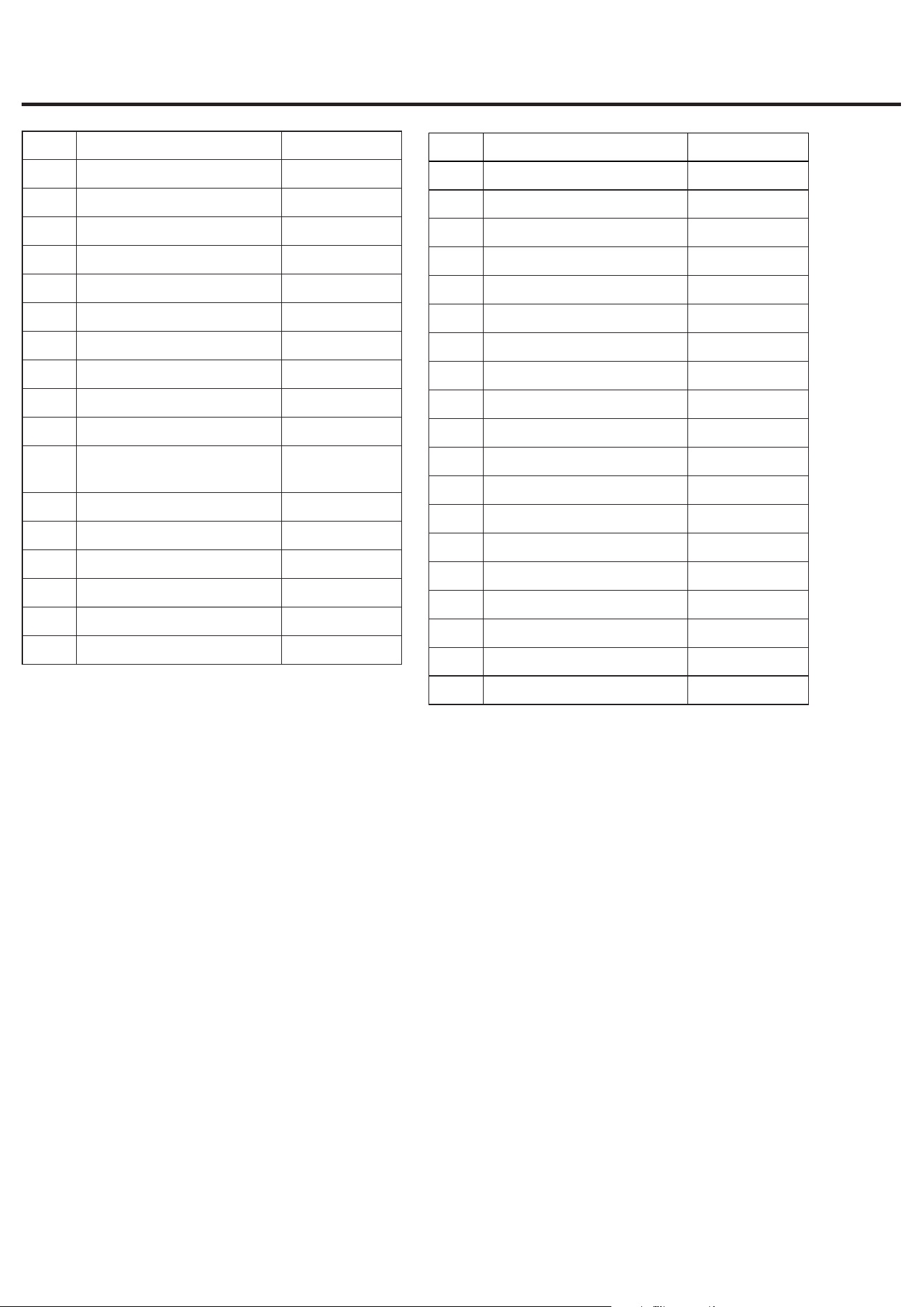
REPLACEMENT PARTS LIST
Part Description Part No.
1 Warming Rack G22483-010
2 Cooking Grid G22483-020
3 Heat Plate G22483-030
4 Lid Handle G22483-040
5 Lid* G22483-050
6 Back Ambient Probe G22483-060
7 Grill Body Assembly* G22483-070
8 Main Burner* G22483-080
9 Grease Tray* G22483-090
10 Left Side Shelf G22483-100
11 Digital Controller* G22483-110
12 Ambient Probe A G22483-120
13 Ambient Probe B G22483-130
14 Control Knob Bezel G1143-090
15 Control Knob G22483-140
16 Regulator & Hose Assembly* B0308-A24
17 Right Side Shelf G22483-150
* Pre-assembled
Part Description Part No.
18 Side Burner Grid B0404-C03
19 Side Burner G22483-160
20 Grease Cup B0219-HA0
21 Left Cart Frame G22483-170
22 Upper Front Panel G22483-180
23 LP Gas Tank Retainer Wire G1461-010
24 Right Cart Frame G22483-190
25 Center Table G22483-200
26 Back Cart Frame G22483-210
27 Door Handle G22483-220
28 Left Door G22483-230
29 Propane Tank Scale G22483-240
30 Right Door G22483-250
31 Lighing Rod* B0223-D04
32 Lower Magnet G22483-260
33 Bottom Panel G22483-270
34 Caster G22483-280
35 Locking Caster G22483-290
36 Upper Magnet G22483-300
Printed in China