
PLANNING GUIDE
WINE CABINET & BEVERAGE CENTER
RS2435V2RT1 I RS2435V2R1 I RS2435SBLT1 I RS2435SBL1
PAGE 290003302B PLANNING GUIDE REFRIGERATION VERSION B - APRIL 2024 © FISHER & PAYKEL LIMITED 2024
PLANNING GUIDE | REFRIGERATION RS2435V2RT1 | RS2435V2R1 | RS2435SBLT1 | RS2435SBL1
This comprehensive Planning Guide provides you with the framework and tools to achieve your desired design outcome with Fisher & Paykel appliances. In this guide, you will
find a range of conceptual, detailed, and dimensional product information to bring your ideas to life and create spaces that truly reflect your vision.
CONCEPT DESIGN PAGE DEVELOPED AND DETAILED DESIGN PAGE DEVELOPED AND DETAILED DESIGN PAGE
Design Choices
Design Choices 4
Specification Guide
Integrated Wine Cabinet 6
Integrated Beverage Center 8
Multiple Installation 10
CONTENTS
Data Sheets
Wine Cabinet + Stainless Steel Door 12
Wine Cabinet + Custom Door Panel 13
Beverage Center + Stainless Steel Door 14
Beverage Center + Custom Door Panel 15
Design Information Planning
Hinge Articulation 17
Door Opening Clearance 18
Custom Panel Preparation - Solid 20
Custom Panel Preparation - Window 21
Custom Panel Door Panel Options 22
Services
Services 24
Handle Data Sheets
Professional Handle 26
Fine Aluminium Handle 27
Fine Round Handle 28
Classic Handle 29
i
High-level product information
for the initial stages of
conceptualising and refining
your design.
i
Detailed information, including
product specs and dimensions,
to support you in the advanced
design stages.

© FISHER & PAYKEL LIMITED 2024 PAGE 390003302B PLANNING GUIDE REFRIGERATION - VERSION B - APRIL 2024
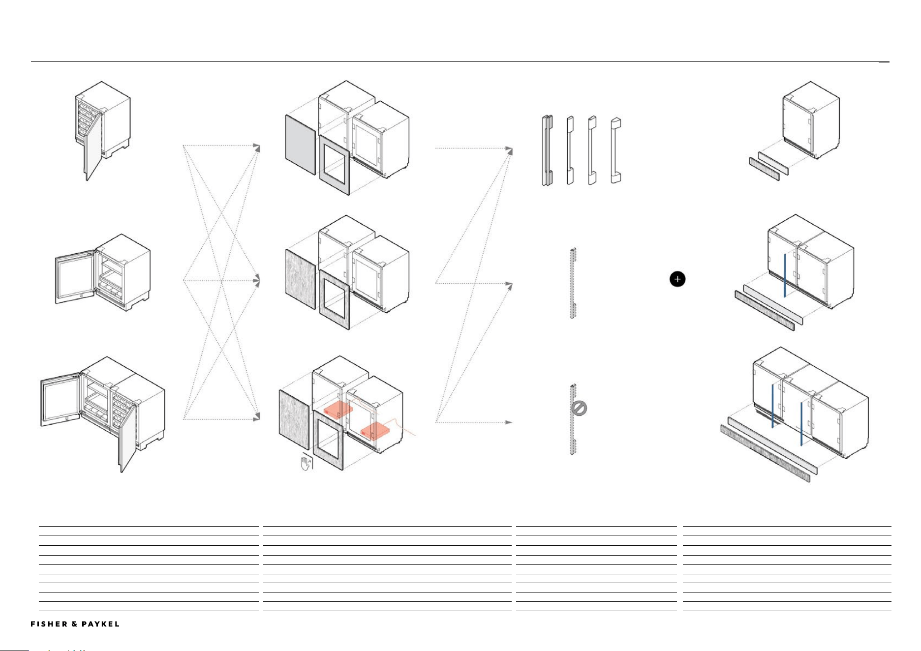
DESIGN CHOICES
PAGE 490003302B PLANNING GUIDE REFRIGERATION VERSION B - APRIL 2024 © FISHER & PAYKEL LIMITED 2024
MODELS
DOOR PANELS
HANDLES
STAINLESS STEEL TOE KICK AND JOINER KIT
Left Hinge Right Hinge
Left Hinge
Right Hinge
1
Fine Aluminium Handle AHD5RD35
Toe Kick Joiner Kit
Integrated Wine Cabinet - Glass door RS2435V2RT1 Solid Stainless Steel Door Panel RD2435L RD2435R
2
Fine Black Aluminium Handle AHD5RD35B Single Installation AKRS2304 Not required
Integrated Wine Cabinet - Solid door RS2435V2R1 Glass Stainless Steel Door Panel RD2435VL RD2435VR
3
Fine Round Handle AHSRD35 Dual Installation AKRS4704 AJRS35LR (1x)
Integrated Beverage Center - Glass door RS2435SBLT1
4
Classic Handle AHCLRD35 Triple Installation AKRS7104 AJRS35LR (2x)
Integrated Beverage Center - Solid door RS2435SBL1 Assisted Opening Accessory OPIN1
5
Professional Handle AHP3RD35
Note: All models can achieve opposite hinge location using the supplied parts Note: Custom Door Panels to be manufactured and fitted by cabinet maker Note: Custom handles to be fitted by cabinet maker Note: Custom Toe Kick to be manufactured and fitted by cabinet maker
DESIGN CHOICES | WINE CABINET & BEVERAGE CENTER
Accessory Handle
Custom Handle
No handle
Stainless Steel Panels
Custom Door Panels
Custom Door Panels and
Assisted Opening Accessory
Integrated Wine Cabinet
Integrated Beverage Centre
Dual Installation
Single Installation
Dual Installation
Triple Installation
1 2 3 4 5
<< CONTENTS

© FISHER & PAYKEL LIMITED 2024 PAGE 590003302B PLANNING GUIDE REFRIGERATION - VERSION B - APRIL 2024
SPECIFICATION GUIDE
The models shown in this Planning Guide may not be available in all markets and are subject to change at any time. Product specifications may vary from those shown. This Planning Guide should not be used as installation guidance for any
product. Further information is required to safely and correctly install the products featured here. Specific installation guidance will be available soon on our website fisherpaykel.com
PAGE 6PLANNING GUIDE REFRIGERATION - VERSION B - APRIL 202490003302B © FISHER & PAYKEL LIMITED 2024
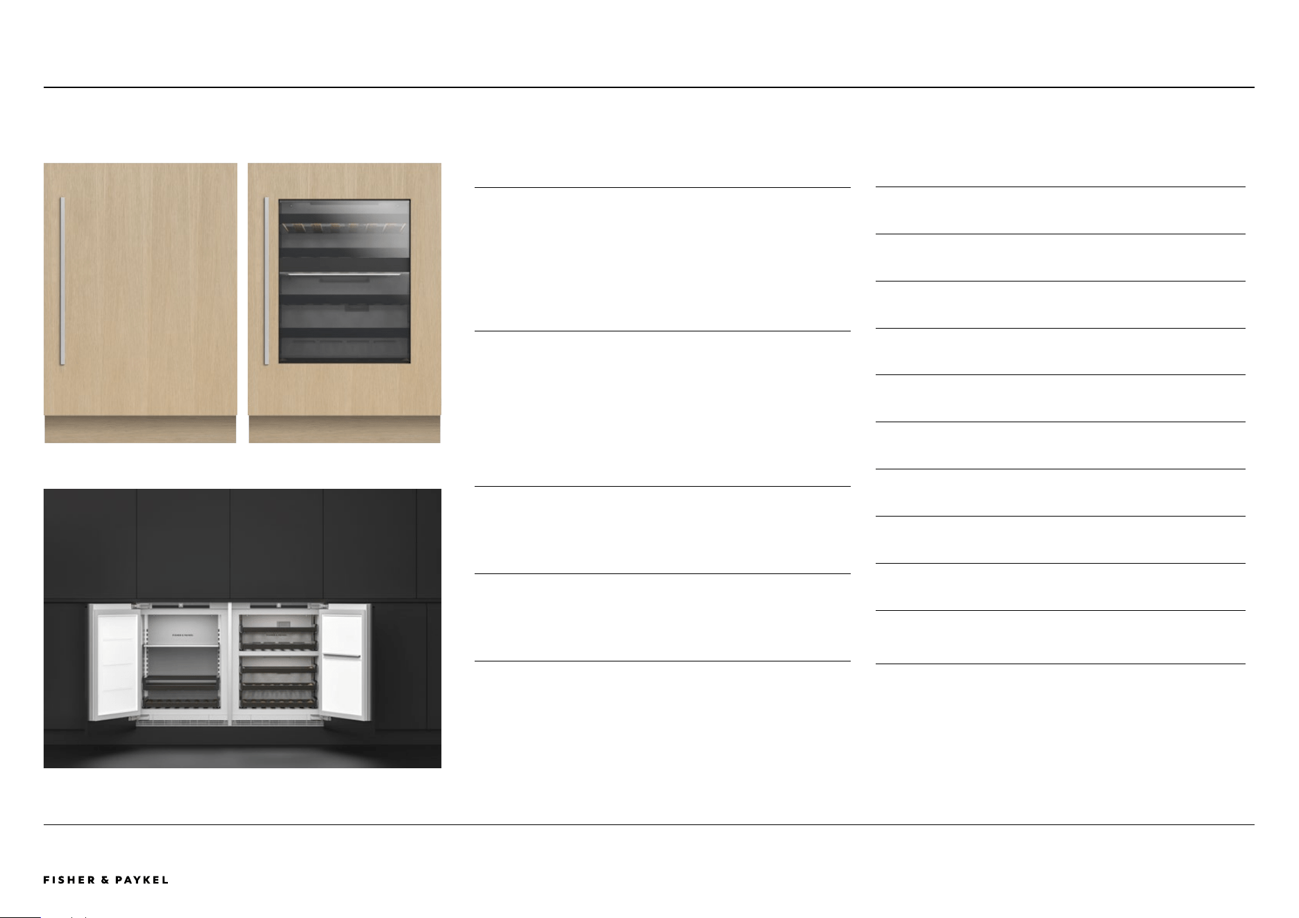
OVERVIEW
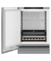
Designed for wine lovers, this under-counter wine cabinet
seamlessly fits in any space of the evolving home. Boasting
premium oak slide-out shelves and a UV-tempered glass
door, it elegantly showcases up to 35 bottles. Featuring dual
temperature zones and specialised modes for Red, White,
Sparkling, and Cellar wines, this versatile cabinet provides
the perfect environment for all wine varieties.
PRODUCTS
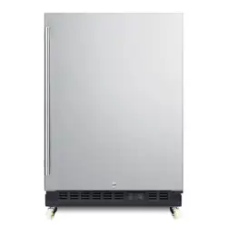
RS2435V2RT1 Integrated Wine Cabinet
Glass Door, Panel Ready or Stainless Steel Panel, Right Hinge
(All models can achieve opposite hinge location using the
supplied parts)
RS2435V2R1 Integrated Wine Cabinet
Solid Door, Panel Ready or Stainless Steel Panel, Right Hinge
(All models can achieve opposite hinge location using the
supplied parts)
FEATURES
1 Integrates into any setting within the home, from the bar
to the master suite – the choices are endless
2 Four specialised wine modes for Red, White, Sparkling,
and Cellar wines
3 Designed to fit flush, with 3/16" gaps and no visible hinges
or grilles
4 Premium oak slide-out shelves for convenient access and
storage
5 Accommodates up to 35 bottles, providing ample space
for a diverse collection
6 Features two independent temperature zones to cater for
different wine varieties
7 UV-tempered glass door elegantly displays and protects
wine
8 Intuitive interface for easy temperature control and mode
selection
9 Internal LED lighting provides beautiful illumination,
showcasing the collection
!0 Wi-Fi enabled for remote temperature control from the
SmartHQ™ app
SPECIFICATION GUIDE | INTEGRATED WINE CABINET, 60CM
RS2435V2RT1 - Glass door with Custom PanelRS2435V2LR1 - Solid door with Custom Panel
RS2435SBL1 & RS2435V2LR1 Side by Side
RS2435V2RT1, RS2435V2R1
<< CONTENTS
The models shown in this Planning Guide may not be available in all markets and are subject to change at any time. Product specifications may vary from those shown. This Planning Guide should not be used as installation guidance for any
product. Further information is required to safely and correctly install the products featured here. Specific installation guidance will be available soon on our website fisherpaykel.com
PAGE 7PLANNING GUIDE REFRIGERATION - VERSION B - APRIL 202490003302B © FISHER & PAYKEL LIMITED 2024
SPECIFICATIONS
Model No.
RS2435V2RT1, RS2435V2R1
Product
Dimensions
H 34 - 35 7/16" W 23 5/16" D 22 13/16
Electrical
Supply 115 V, 60 Hz
Service 10 A
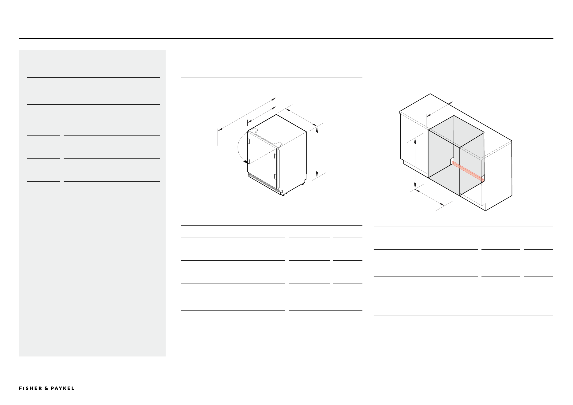
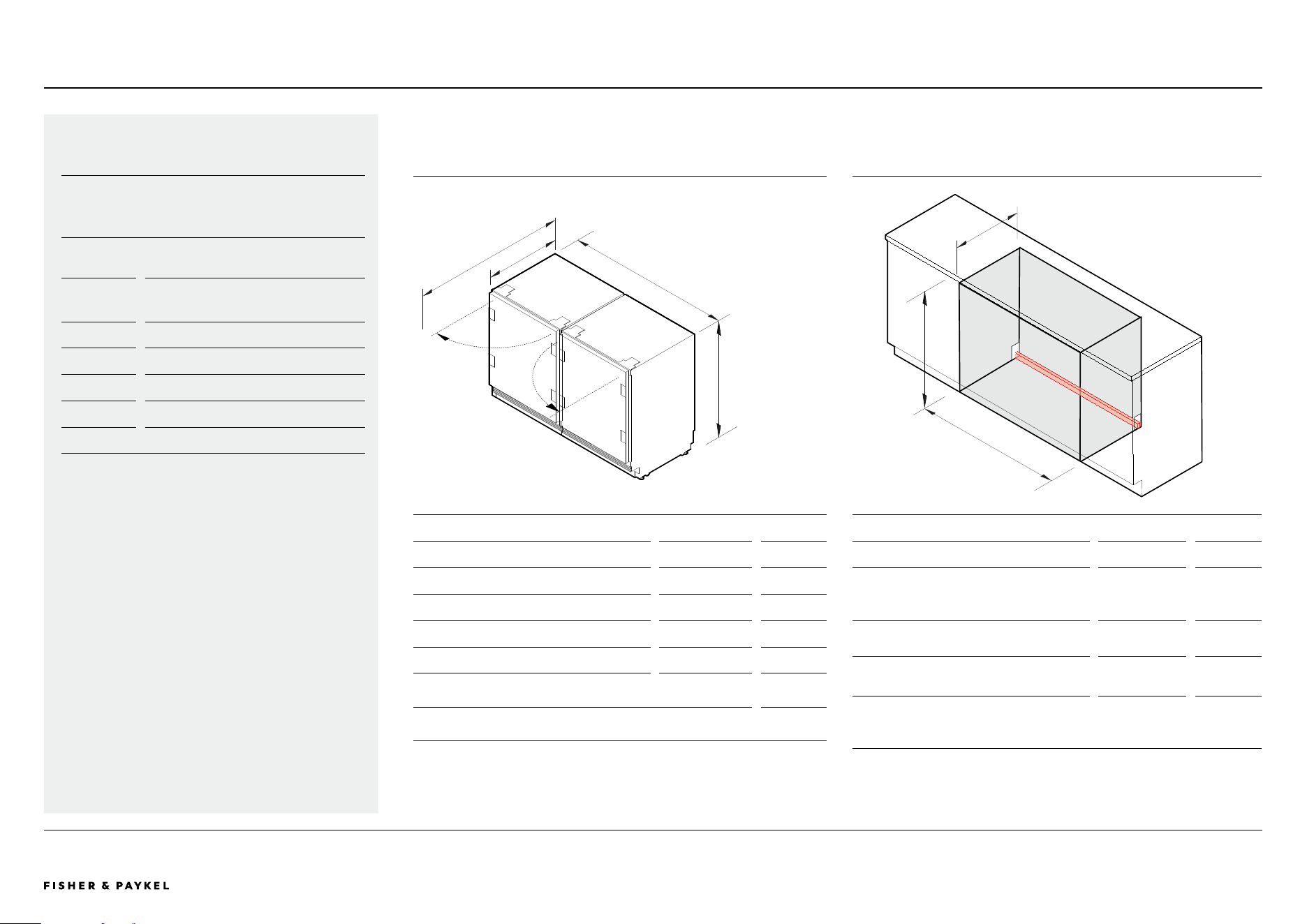
PRODUCT DIMENSIONS
inch mm
A Overall height 34 - 35 7/16 864 - 900
B Overall width 23 5/16 592
C Overall depth*
22 13/16 579
D Overall depth with the door open*
47 1/4 1200
Height from floor to bottom of door panel** 9/16 – 5 15/16 15 - 150
Depth of toe kick (excl. front door and toe
kick panels)**
2 - 4
50 - 100
Splitline heights achievable (height from
floor to top of door panel)
33 7/8 - 35 5/16 861 - 897
Maximum custom door panel thickness of 3/4” (19mm)
*Excluding door panel and handle
**Applies to custom door panels
*** The grille becomes visible at heights over 100mm
Cd
A
B
CAVITY DIMENSIONS: STANDARD INSTALLATION
inch mm
A Height
34 - 35 7/16 864 - 900
B Minimum width
23 5/8 600
C Minimum overall cavity depth with
service to the side
23 5/8 600
c Minimum overall cavity depth
with service behind
25 9/16 650
Service area
H 1 7/16" x W 23 5/8" x D 13/16"
A
B
C
RS2435V2RT1, RS2435V2R1SPECIFICATION GUIDE | INTEGRATED WINE CABINET, 60CM
<< CONTENTS
The models shown in this Planning Guide may not be available in all markets and are subject to change at any time. Product specifications may vary from those shown. This Planning Guide should not be used as installation guidance for any
product. Further information is required to safely and correctly install the products featured here. Specific installation guidance will be available soon on our website fisherpaykel.com
PAGE 8PLANNING GUIDE REFRIGERATION - VERSION B - APRIL 202490003302B © FISHER & PAYKEL LIMITED 2024
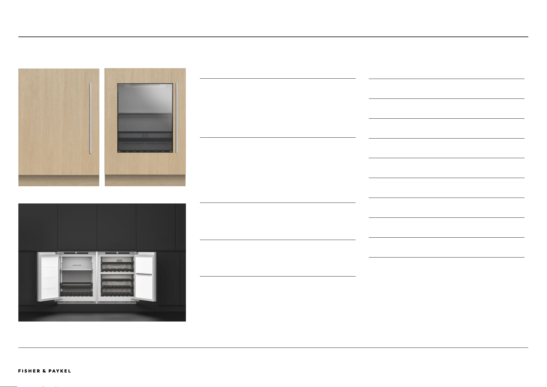
OVERVIEW
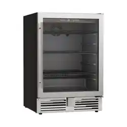
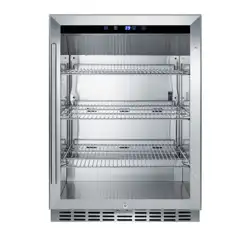
Experience the luxury of the Integrated Beverage Center.
Seamlessly blending into any home setting, its adjustable
shelves and full-depth wine shelf elegantly house your
favourite beverages. With a UV-resistant glass door and soft
LED lighting, this Beverage Center is a blend of style and
functionality, oering optimal conditions for all drinks.
PRODUCTS
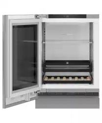
RS2435SBLT 1 Integrated Beverage Center
Glass Door, Panel Ready or Stainless Steel Panel, Left Hinge
(All models can achieve opposite hinge location using the
supplied parts)
RS2435SBL1 Integrated Beverage Center
Solid Door, Panel Ready or Stainless Steel Panel, Left Hinge
(All models can achieve opposite hinge location using the
supplied parts)
FEATURES
1 Integrates into any setting within the home, from the bar
to the master suite – the choices are endless
2 Designed to fit flush, with 3/16" gaps and no visible hinges
or grilles
3 Adjustable temperature control helps to keep drinks at the
ideal temperature
4 Customisable beverage shelf with adjustable gates ensures
contents remain upright and neatly organised
5 Spacious 4.6 cu ft capacity, with full-depth wine shelf that
can accommodate up to seven bottles
6 Wi-Fi enabled for remote temperature control from the
SmartHQ™ app
7 Internal LED lighting provides beautiful illumination,
showcasing the collection
8 UV-tempered glass door elegantly displays and protects
beverages
9 Intuitive interface for easy temperature control and mode
selection
SPECIFICATION GUIDE | INTEGRATED BEVERAGE CENTER, 60CM
RS2435SBLT1 - Glass door with Custom PanelRS2435SBL1 - Solid door with Custom Panel
RS2435SBL1 & RS2435V2LR1 Side by Side
RS2435S BLT 1 , RS2435SBL1
<< CONTENTS
The models shown in this Planning Guide may not be available in all markets and are subject to change at any time. Product specifications may vary from those shown. This Planning Guide should not be used as installation guidance for any
product. Further information is required to safely and correctly install the products featured here. Specific installation guidance will be available soon on our website fisherpaykel.com
PAGE 9PLANNING GUIDE REFRIGERATION - VERSION B - APRIL 202490003302B © FISHER & PAYKEL LIMITED 2024
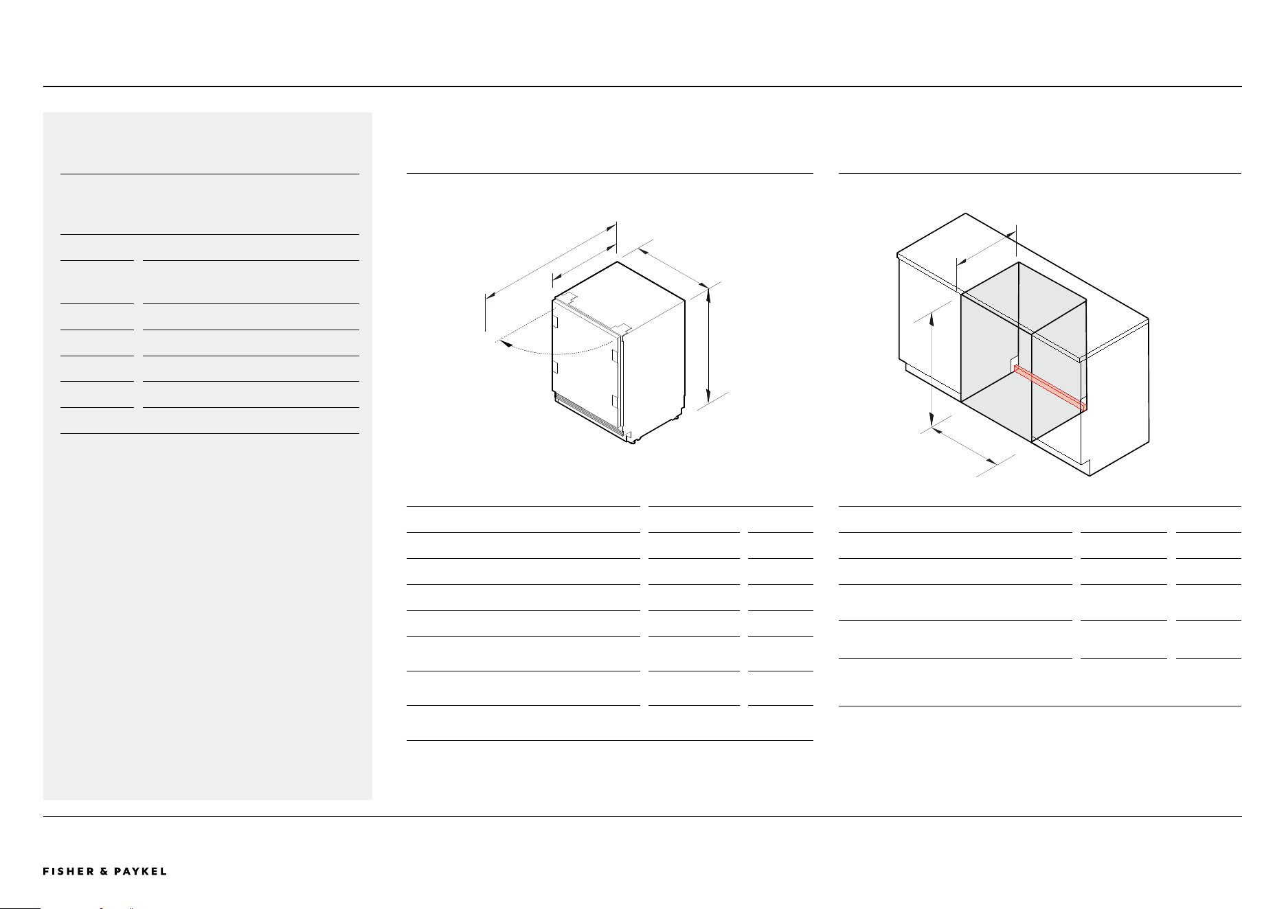
C
A
B
d
C
A
B
RS2435S BLT 1 , RS2435SBL1SPECIFICATION GUIDE | INTEGRATED BEVERAGE CENTER, 60CM
PRODUCT DIMENSIONS
inch mm
A Overall height 34 - 35 7/16 864 - 900
B Overall width 23 5/16 592
C Overall depth*
22 13/16 579
D Overall depth with the door open*
47 1/4 1200
Height from floor to bottom of door
panel** ***
9/16 – 5 15/16
15 - 150
Depth of toe kick (excl. front door and toe
kick panels)**
2 - 4
50 - 100
Splitline heights achievable (height from
floor to top of door panel)
33 7/8 - 35 5/16 861 - 897
Maximum custom door panel thickness of 3/4” (19mm)
*Excluding door panel and handle
**Applies to custom door panels
*** The grille becomes visible at heights over 100mm
CAVITY DIMENSIONS: STANDARD INSTALLATION
inch mm
A Height
34 - 35 7/16 864 - 900
B Minimum width
23 5/8 600
C Minimum overall cavity depth with
service to the side
23 5/8 600
c Minimum overall cavity depth
with service behind
25 9/16 650
Service area
H 1 7/16" x W 23 5/8" x D 13/16"
SPECIFICATIONS
Model No.
RS2435SBLT1, RS2435SBL1
Product
Dimensions
H 34 - 35 7/16" W 23 5/16" D 22 13/16
Electrical
Supply 115 V, 60 Hz
Service 10 A
<< CONTENTS
The models shown in this Planning Guide may not be available in all markets and are subject to change at any time. Product specifications may vary from those shown. This Planning Guide should not be used as installation guidance for any
product. Further information is required to safely and correctly install the products featured here. Specific installation guidance will be available soon on our website fisherpaykel.com
PAGE 10PLANNING GUIDE REFRIGERATION - VERSION B - APRIL 202490003302B © FISHER & PAYKEL LIMITED 2024
C
A
B
C
d
b
A
RS2435V2RT1, RS2435V2R1, RS2435SBLT1, RS2435SBL1
PRODUCT DIMENSIONS
inch mm
A Overall height 34 - 35 7/16 864 - 900
B Overall width - dual installation 46 7/8 1190
C Overall depth*
22 13/16 579
D Overall depth with the door open*
47 1/4 1200
Height from floor to bottom of door panel** 9/16 –5 15/16 15-150
Depth of toe kick (excl. front door and toe
kick panels)**
2 - 4
50 - 100
Splitline heights achievable (height from
floor to top of door panel)
33 7/8 - 35 5/16 861 - 897
Maximum custom door panel thickness of 3/4” (19mm)
*Excluding door panel and handle
**Applies to custom door panels
*** The grille becomes visible at heights over 100mm
CAVITY DIMENSIONS: STANDARD INSTALLATION
inch mm
A Height
34 - 35 7/16 864 - 900
B Minimum width dual installation
Minimum width triple installation
47 1/4
70 7/ 8
1200
1800
C Minimum overall cavity depth with
service to the side*
24 610
c Minimum overall cavity depth
with service behind
25 9/16 650
Service area dual installation H 1 7/16" x W 47 1/4" x D 13/16"
Service area triple installation H 1 7/16" x W 70 7/8" x D 13/16"
*Cavity depth allows space for the joiner kit bracket
SPECIFICATIONS
Model No.
RS2435V2RT1, RS2435V2R1,
RS2435SBLT1, RS2435SBL1
Product
Dimensions
H 34 - 35 7/16" W 23 5/16" D 22 13/16
Electrical
Supply 115 V, 60 Hz
Service 10 A
SPECIFICATION GUIDE | DUAL INSTALLATION, 60CM
<< CONTENTS

© FISHER & PAYKEL LIMITED 2024 PAGE 1190003302B PLANNING GUIDE REFRIGERATION - VERSION B - APRIL 2024
DATA SHEETS
IMPORTANT NOTE: Throughout this guide, dimensions may vary by ±2mm
(1/16''). Please read the Installation Guide for detailed information on
installing the product. For full installation instructions visit fisherpaykel.com
PAGE 1290003302B PLANNING GUIDE REFRIGERATION - VERSION B - APRIL 2024 © FISHER & PAYKEL LIMITED 2024
Model No:
RS2435V2RT1 - Right hinge, Glass window
RS2435V2R1 - Right hinge, Solid door
Shown with
Stainless Steel Panel with Glass RD2435VR - RS2435V2RT1
Stainless Steel Panel Solid RD2435R - RS2435V2R1
Handle Kit AHD5RD35(B)
Stainless Steel Toe Kick Panel AKRS2304
Note:
All models can achieve opposite hinge location using the supplied parts
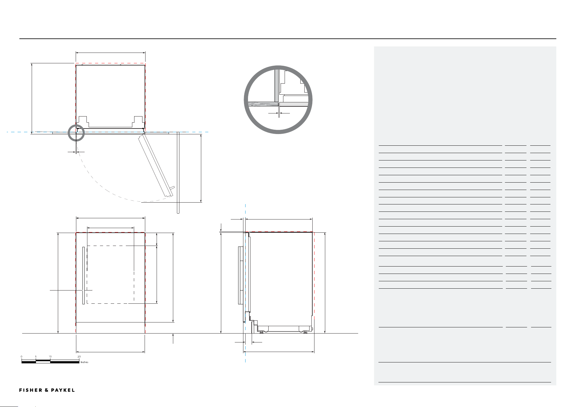
Product Dimensions
Inch
mm
a Overall height of product
34 4/16
870
B Overall width of product
23 5/16
592
C Overall depth of product (excl. front door panels)
22 13/16
579
D Height from top of door panel to floor
34 2/16
867
e Minimum cabinetry clearance from side of door panel
3/16
4
f Minimum cabinetry clearance from top of door panel
1/8
3
g Height of door panel
30 3/16
767
h Depth of door panel
12/16
19
i Height from floor to bottom door panel
3 15/16
100
j Depth of toe kick (excl. front door and toe kick panels)
2-4
50 – 100
k Width glass window
15 15/16
404
l Height glass window
19 9/16
496
m Top of door panel to top of cut-out/window
4 7/16
113
n Depth of door (90° open, measured from front of cabinetry)
23 10/16
600
Cavity Dimensions
inch
mm
o Overall height of cavity
34 4/16
870
p Overall width of cavity
23 10/16
600
q Minimum overall depth of cavity:
When services are located outside of cavity (shallow)*
When services are located in the neighbouring cavities
When services are located at rear of cavity (deep)
*Multiple product installation cavity depth is 24" (610mm), this to
allow space for the joiner kit bracket
23 10/16
24
25 10/16
600
610
650
Notes:
Product shown installed on the floor. Slide into cabinetry position.
Alternatively can be installed on a plinth. Adjust your cavity height accordingly.
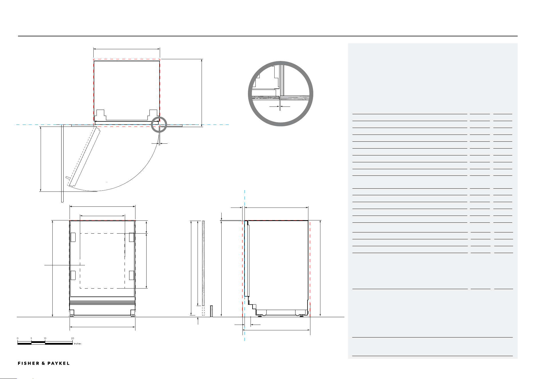
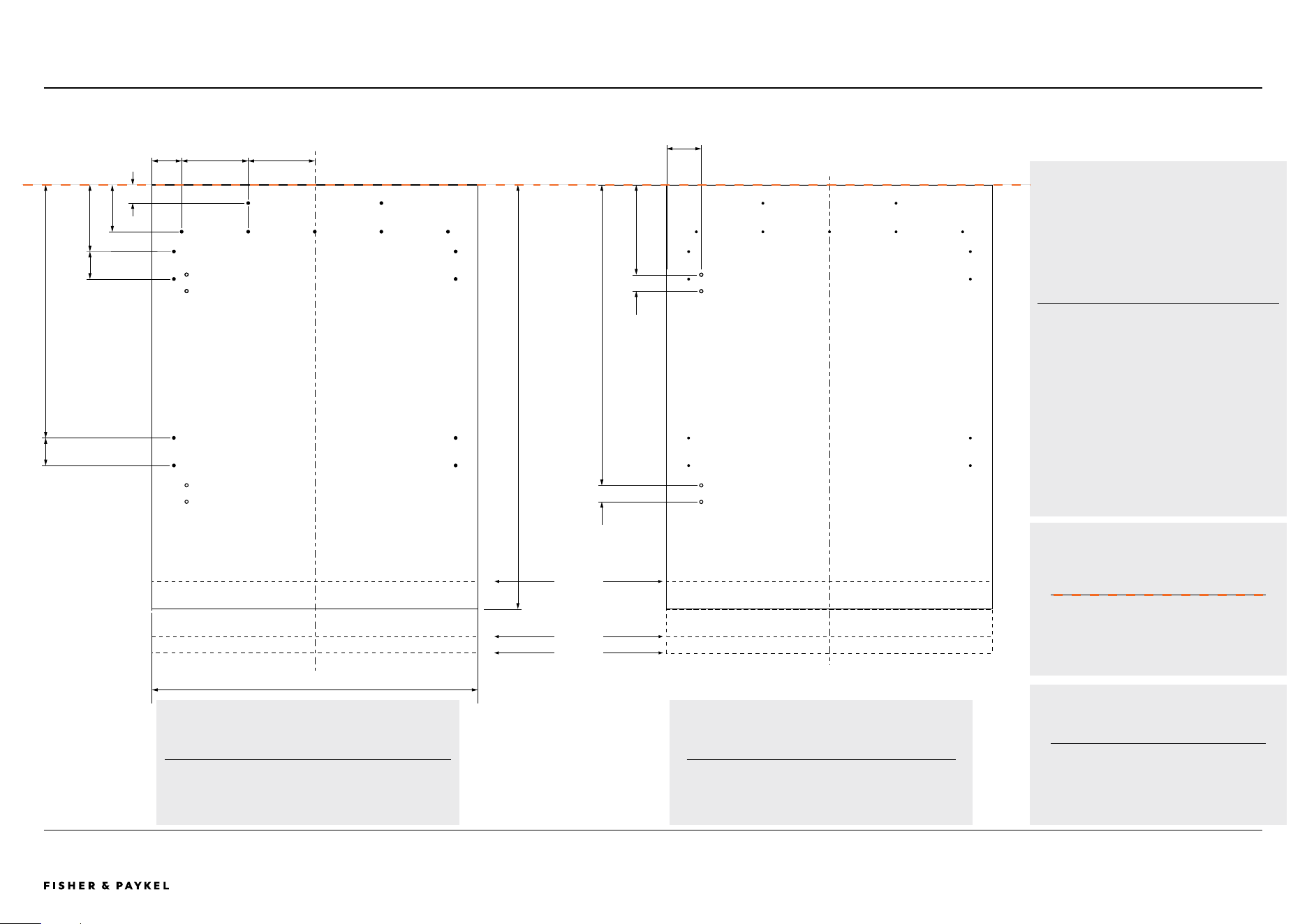
PRODUCT & CAVITY DIMENSIONS
Integrated Wine Cabinets with Stainless Steel Door Panels
p
q
B
f
C
A
p
o
PLAN VIEW
DATUM: FRONT OF CHASSIS
DATUM:
FRONT OF CHASSIS
n
D
h
j
22 13/16
34 4/16
23 5/16
VERTICAL GAP
CLEARANCE FROM SIDE
OF DOOR PANEL
Glass window model
RS2435V2RT1 and
door panel RD2435VR
g
l
m
k
i
e
RS2435V2RT1, RS2435V2R1DATA SHEET | INTEGRATED + STAINLESS STEEL DOOR
INDICATES CABINETRY / PRODUCT DATUM -------------------------
INDICATES CABINETRY CLEARANCES --------------------------------
3/16
Q
FLOOR
FRONT VIEW PROFILE VIEW
<< CONTENTS
IMPORTANT NOTE: Throughout this guide, dimensions may vary by ±2mm
(1/16''). Please read the Installation Guide for detailed information on
installing the product. For full installation instructions visit fisherpaykel.com
PAGE 1390003302B PLANNING GUIDE REFRIGERATION - VERSION B - APRIL 2024 © FISHER & PAYKEL LIMITED 2024
Model No:
RS2435V2RT1 - Right hinge
RS2435V2R1 - Right hinge
Note:
All models can achieve opposite hinge location using the supplied parts
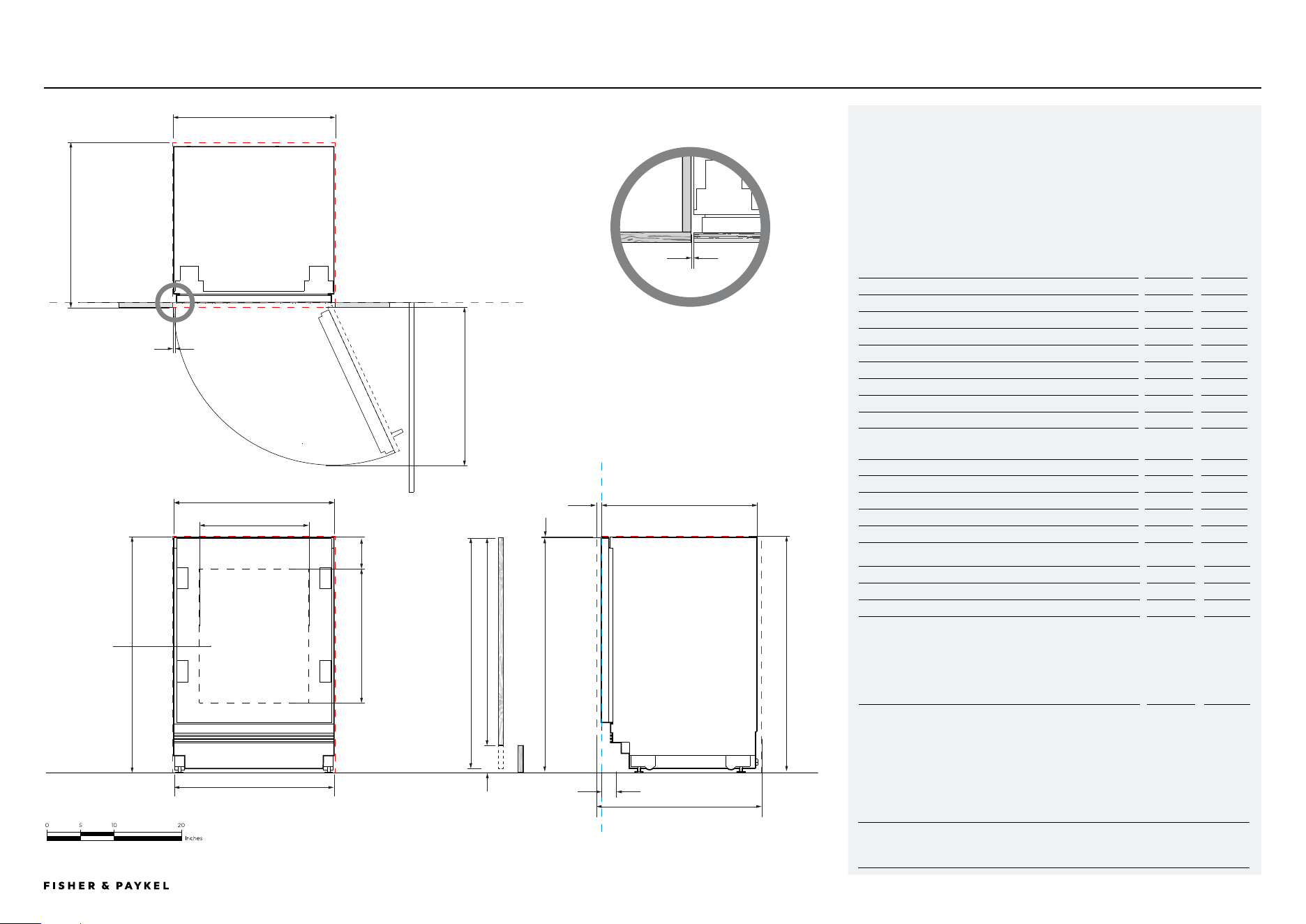
Product Dimensions
inch
mm
a Overall height of product
34-35 7/16
864 - 900
B Overall width of product
23 5/16
592
C Overall depth of product (excl. front door panels)
22 13/16
579
d Minimum cabinetry clearance from side of door panel
3/16
4
e Minimum cabinetry clearance from top of door panel
1/8
3
f Maximum height of custom door panel
34 12/16
882
g Minimum height of custom door panel
30
761
h Depth of custom door panel
5/8-3/4
16 - 19
i Height from floor to bottom of door panel
9/16 –
5 15/16
15 - 150
j Depth of toe kick (excl. front door and toe kick panels)
2-4
50 – 100
k Width glass window
15 15/16
404
l Height glass window
19 9/16
496
m Top edge of glass to top of custom door panel
4 7/16
113
n Depth of door (90° open, measured from front of cabinetry)
23 10/16
600
Cavity Dimensions
inch
mm
o Overall height of cavity
34-35 7/16
864 - 900
p Overall width of cavity
23 10/16
600
q Minimum overall depth of cavity:
When services are located outside of cavity (shallow)*
When services are located in the cabinet above the cavity
When services are located at rear of cavity (deep)
*Multiple product installation cavity depth is 24" (610mm), this to
allow space for the joiner kit bracket
23 10/16
24
25 10/16
600
610
650
PRODUCT & CAVITY DIMENSIONS
Integrated Wine Cabinets with Custom Door Panels
RS2435V2RT1, RS2435V2R1DATA SHEETS | INTEGRATED + CUSTOM DOOR PANEL
INDICATES CABINETRY / PRODUCT DATUM -------------------------
INDICATES CABINETRY CLEARANCES --------------------------------
3/16
P
q
B
e
C
A
P
o
PLAN VIEW
q
DATUM: FRONT OF CHASSIS
DATUM:
FRONT OF CHASSIS
n
D
h
j
22 13/16
34 - 35 7/16
23 5/16
VERTICAL GAP
CLEARANCE FROM SIDE
OF DOOR PANEL
Glass window model
RS2435SBLT1
F
l
m
k
G
D
i
FRONT VIEW PROFILE VIEW
FLOOR
<< CONTENTS
IMPORTANT NOTE: Throughout this guide, dimensions may vary by ±2mm
(1/16''). Please read the Installation Guide for detailed information on
installing the product. For full installation instructions visit fisherpaykel.com
PAGE 1490003302B PLANNING GUIDE REFRIGERATION - VERSION B - APRIL 2024 © FISHER & PAYKEL LIMITED 2024
INDICATES CABINETRY / PRODUCT DATUM -------------------------
INDICATES CABINETRY CLEARANCES --------------------------------
RS2435BLT1, RS2435BL1DATA SHEET | INTEGRATED + STAINLESS STEEL DOOR PANEL
Model No:
RS2435BLT1 - Right hinge, Glass window
RS2435BL1 - Right hinge, Solid door
Shown with
Stainless Steel Panel with Glass RD2435VR - RS2435B2LT1
Stainless Steel Panel Solid RD2435R - RS2435B2L1
Handle Kit AHD5RD35(B)
Stainless Steel Toe Kick Panel AKRS2304
Note:
All models can achieve opposite hinge location using the supplied parts
Product Dimensions
Inch
mm
a Overall height of product
34 4/16
870
B Overall width of product
23 5/16
592
C Overall depth of product (excl. front door panels)
22 13/16
579
D Height from top of door panel to floor
34 2/16
867
e Minimum cabinetry clearance from side of door panel
3/16
4
f Minimum cabinetry clearance from top of door panel
1/8
3
g Height of door panel
30 3/16
767
h Depth of door panel
12/16
19
i Height from floor to bottom door panel
3 15/16
100
j Depth of toe kick (excl. front door and toe kick panels)
2-4
50 – 100
k Width glass window
15 15/16
404
l Height glass window
19 9/16
496
m Top of door panel to top of cut-out/window
4 7/16
113
n Depth of door (90° open, measured from front of cabinetry)
23 10/16
600
Cavity Dimensions
inch
mm
o Overall height of cavity
34 4/16
870
p Overall width of cavity
23 10/16
600
q Minimum overall depth of cavity:
When services are located outside of cavity (shallow)*
When services are located in the neighbouring cavities
When services are located at rear of cavity (deep)
*Multiple product installation cavity depth is 24" (610mm), this to
allow space for the joiner kit bracket
23 10/16
24
25 10/16
600
610
650
Notes:
Product shown installed on the floor. Slide into cabinetry position.
Alternatively can be installed on a plinth. Adjust your cavity height accordingly.
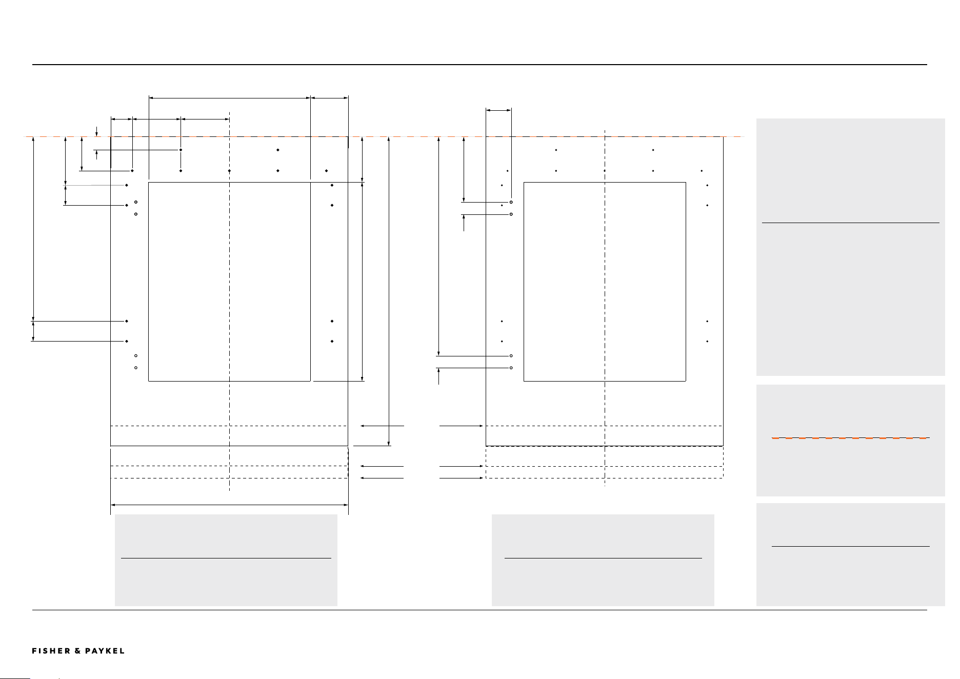
PRODUCT & CAVITY DIMENSIONS
Integrated Beverage Centers with Stainless Steel Door Panels
q
B
f
C
A
p
o
PLAN VIEW
DATUM: FRONT OF CHASSIS
DATUM:
FRONT OF CHASSIS
n
D
h
j
22 13/16
34 4/16
23 5/16
VERTICAL GAP
CLEARANCE FROM SIDE
OF DOOR PANEL
Glass window model
RS2435V2RT1 and
door panel RD2435VR
g
l
m
k
i
e
3/16
Q
P
FLOOR
PROFILE VIEWFRONT VIEW
<< CONTENTS
IMPORTANT NOTE: Throughout this guide, dimensions may vary by ±2mm
(1/16''). Please read the Installation Guide for detailed information on
installing the product. For full installation instructions visit fisherpaykel.com
PAGE 1590003302B PLANNING GUIDE REFRIGERATION - VERSION B - APRIL 2024 © FISHER & PAYKEL LIMITED 2024
INDICATES CABINETRY / PRODUCT DATUM -------------------------
INDICATES CABINETRY CLEARANCES --------------------------------
P
q
B
e
C
A
P
o
PLAN VIEW
q
DATUM: FRONT
OF CHASSIS
DATUM:
FRONT OF CHASSIS
n
D
h
j
FLOOR
22 13/16
34 - 35 7/16
23 5/16
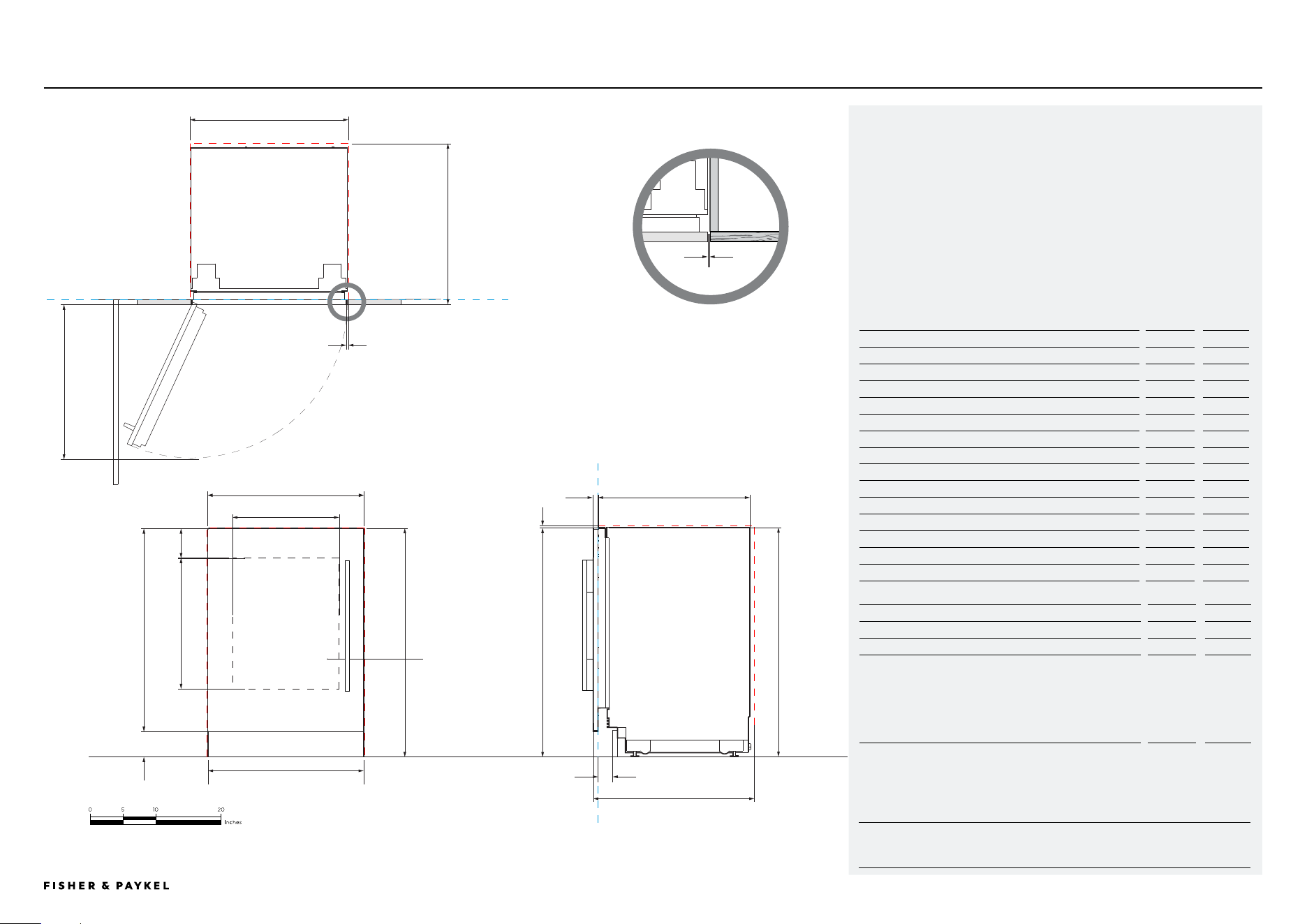
VERTICAL GAP
CLEARANCE FROM SIDE
OF DOOR PANEL
Glass window model
RS2435SBLT1
Fl
m
k
G
D
i
DATA SHEET | INTEGRATED + CUSTOM DOOR PANEL RS2435BLT1, RS2435BL1
3/16
PRODUCT & CAVITY DIMENSIONS
Integrated Beverage Centers with Custom Door Panels
Model No:
RS2435BLT1 - Right hinge
RS2435BL1 - Right hinge
Note:
All models can achieve opposite hinge location using the supplied parts
Product Dimensions
inch
mm
a Overall height of product
34-35 7/16
864 - 900
B Overall width of product
23 5/16
592
C Overall depth of product (excl. front door panels)
22 13/16
579
d Minimum cabinetry clearance from side of door panel
3/16
4
e Minimum cabinetry clearance from top of door panel
1/8
3
f Maximum height of custom door panel
34 12/16
882
g Minimum height of custom door panel
30
761
h Depth of custom door panel
5/8-3/4"
16 - 19
i Height from floor to bottom of door panel
9/16 –
5 15/16
15 - 150
j Depth of toe kick (excl. front door and toe kick panels)
2-4
50 – 100
k Width glass window
15 15/16
404
l Height glass window
19 9/16
496
m Top edge of glass to top of custom door panel
4 7/16
113
n Depth of door (90° open, measured from front of cabinetry)
23 10/16
600
Cavity Dimensions
inch
mm
o Overall height of cavity
34-35 7/16
864 - 900
p Overall width of cavity
23 10/16
600
q Minimum overall depth of cavity:
When services are located outside of cavity (shallow)*
When services are located in the cabinet above the cavity
When services are located at rear of cavity (deep)
*Multiple product installation cavity depth is 24" (610mm), this to
allow space for the joiner kit bracket
23 10/16
24
25 10/16
600
610
650
FRONT VIEW PROFILE VIEW
<< CONTENTS

© FISHER & PAYKEL LIMITED 2024 PAGE 1690003302B PLANNING GUIDE REFRIGERATION - VERSION B - APRIL 2024
DESIGN INFORMATION PLANNING
The models shown in this Planning Guide may not be available in all markets and are subject to change at any time. Product specifications may vary from those shown. This Planning Guide should not be used as installation guidance for any
product. Further information is required to safely and correctly install the products featured here. Specific installation guidance will be available soon on our website fisherpaykel.com
PAGE 17PLANNING GUIDE REFRIGERATION - VERSION B - APRIL 202490003302B © FISHER & PAYKEL LIMITED 2024
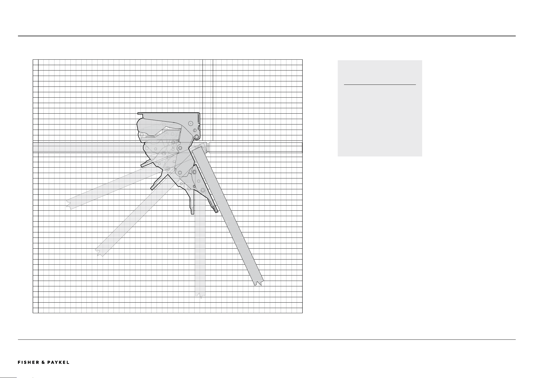
DOOR HINGE
HETTICH K08
Left hand hinge models are
a mirrored version of image
shown
1 Square = 3/8" (10mm)
RS2435V2RT1, RS2435V2R1, RS2435SBLT1, RS2435SBL1PLANNING GUIDE | HINGE ARTICULATION
<< CONTENTS
The models shown in this Planning Guide may not be available in all markets and are subject to change at any time. Product specifications may vary from those shown. This Planning Guide should not be used as installation guidance for any
product. Further information is required to safely and correctly install the products featured here. Specific installation guidance will be available soon on our website fisherpaykel.com
PAGE 18PLANNING GUIDE REFRIGERATION - VERSION B - APRIL 202490003302B © FISHER & PAYKEL LIMITED 2024
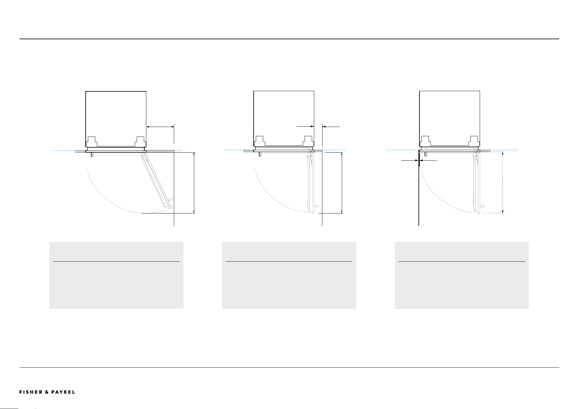
RS2435V2RT1, RS2435V2R1, RS2435SBLT1, RS2435SBL1PLANNING GUIDE | DOOR OPENING CLEARANCE
3 3/16 (80mm)
10 12/16 (273mm)
23 10/16 (600mm)
3/16 (4mm)
FULL INTERNAL ACCESS
115° door opening - full internal access
Minimum dimensions shown are for the contemporary
handle kit AHD5RD35(B). Custom door panel and
handle details need to be taken into account
REDUCED INTERNAL ACCESS
Use hinge limiting pin to restrict door opening to 90° where
necessary
Minimum dimensions shown are for the contemporary handle kit
AHD5RD35(B). Custom door panel and handle details need to
be taken into account
REDUCED INTERNAL ACCESS
Use hinge limiting pin to restrict door opening to 90° where
necessary
Minimum dimensions shown are for the contemporary handle kit
AHD5RD35(B). Custom door panel and handle details need to
be taken into account
23 10/16 (600mm)23 10/16 (600mm)
<< CONTENTS
The models shown in this Planning Guide may not be available in all markets and are subject to change at any time. Product specifications may vary from those shown. This Planning Guide should not be used as installation guidance for any
product. Further information is required to safely and correctly install the products featured here. Specific installation guidance will be available soon on our website fisherpaykel.com
PAGE 19PLANNING GUIDE REFRIGERATION - VERSION B - APRIL 202490003302B © FISHER & PAYKEL LIMITED 2024
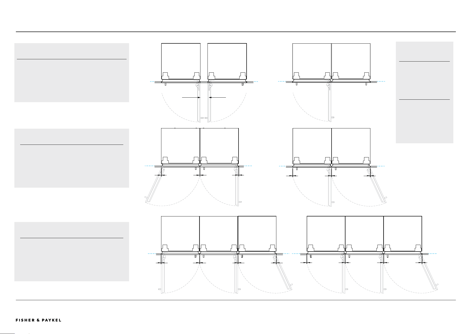
cc c
cc c
dd d dd dd d
HINGE TO HINGE
A Both doors open at the same time - requires space between
models
B Only allows a single door open at a time
Minimum dimensions shown are for the contemporary handle kit
AHD5RD35(B). Custom door panel and handle details need to be
taken into account
Min. 3 15/16 (100mm)
A B
DUAL INSTALLATION
c Stainless steel door panels (gaps equalized during
installation) - 3/16" (5mm)
c Custom door panels (width of custom door panel increased
to maintain 4mm gap across multiple products) - 5/32" (4mm)
TRIPLE INSTALLATION
d Stainless steel door panels (gaps equalized during
installation) - (6mm)
d Custom door panels (width of custom door panel increased
to maintain 4mm gap across multiple products) - 5/32" (4mm)
ADDITIONAL NOTES
Use hinge limiting pin to
restrict door opening to 90°
where necessary.
Minimum dimensions shown
are for the contemporary
handle kit AHD5RD35(B).
Custom door panel and
handle details need to be
taken into account.
RS2435V2RT1, RS2435V2R1, RS2435SBLT1, RS2435SBL1PLANNING GUIDE | DOOR OPENING CLEARANCE
<< CONTENTS
The models shown in this Planning Guide may not be available in all markets and are subject to change at any time. Product specifications may vary from those shown. This Planning Guide should not be used as installation guidance for any
product. Further information is required to safely and correctly install the products featured here. Specific installation guidance will be available soon on our website fisherpaykel.com
PAGE 20PLANNING GUIDE REFRIGERATION - VERSION B - APRIL 202490003302B © FISHER & PAYKEL LIMITED 2024
RS2435V2R1, RS2435SBL1PLANNING GUIDE | CUSTOM PANEL PREPARATION - SOLID
2 8/16
6 7/161 3/16
21 8/161 3/16
2 2/16
4 12/16
4 12/16
3 6/16
1 5/16
2
18 2/16
2
1
2
3
23 5/16
30 6/16 (with bench height 34 4/16
and visual toe toe kick 3 15/16)
BACK OF CUSTOM DOOR PANEL
BRACKET HOLE LOCATIONS
Ø 1/16" (2.5mm) pilot holes,
all holes 5/8" (15mm) deep
Do not penetrate front face
FRONT OF CUSTOM DOOR PANEL
HANDLE HOLE LOCATIONS
All handle holes Ø 4/16" (6mm)
Model No:
RS2435V2R1
RS2435B2L1
VISUAL TOE KICK HEIGHT FROM
FLOOR TO BOTTOM OF DOOR PANEL
1 Visual toe kick height 5 15/16"
(150mm) custom door panel
2" (50mm) shorter
2 Visual toe kick height 2" (50mm)
custom door panel 2" (50mm)
longer
3 Visual toe kick height 5/8" (15mm)
custom door panel 3 6/16 (85mm)
mmlonger
DATUM TOP OF CUSTOM
DOOR PANEL
Allow 1/8" (3 mm) gap between
the top of the custom door
panel and the bench top
CUSTOM PANEL WEIGHT
Maximum custom solid door
panel weight is
12.4lbs (5.6kg)
4 12/16
Custom Panel Preparation - Solid
<< CONTENTS
The models shown in this Planning Guide may not be available in all markets and are subject to change at any time. Product specifications may vary from those shown. This Planning Guide should not be used as installation guidance for any
product. Further information is required to safely and correctly install the products featured here. Specific installation guidance will be available soon on our website fisherpaykel.com
PAGE 21PLANNING GUIDE REFRIGERATION - VERSION B - APRIL 202490003302B © FISHER & PAYKEL LIMITED 2024
RS2435V2RT1, RS2435SB LT 1PLANNING GUIDE | CUSTOM PANEL PREPARATION - WINDOW
2 8/16
6 7/161 3/16
21 8/161 3/16
2 2/16
4 12/16
4 12/16
3 6/16
1 5/16
2
18 2/162
1
2
3
23 5/16
19 9/16
15 15/16
4 7/16
3 11/16
BACK OF CUSTOM DOOR PANEL
BRACKET HOLE LOCATIONS
Ø 1/16" (2.5mm) pilot holes,
all holes 5/8" (15mm) deep
Do not penetrate front face
FRONT OF CUSTOM DOOR PANEL
HANDLE HOLE LOCATIONS
All handle holes Ø 4/16" (6mm)
Model No:
RS2435V2RT1
RS2435B2LT1
VISUAL TOE KICK HEIGHT FROM
FLOOR TO BOTTOM OF DOOR PANEL
1 Visual toe kick height 5 15/16"
(150mm) custom door panel
2" (50mm) shorter
2 Visual toe kick height 2" (50mm)
custom door panel 2" (50mm)
longer
3 Visual toe kick height 5/8" (15mm)
custom door panel 3 6/16 (85mm)
DATUM TOP OF CUSTOM
DOOR PANEL
Allow 5/8" (3 mm) gap between
the top of the custom door
panel and the bench top
CUSTOM PANEL WEIGHT
Maximum custom window door
panel weight is
8.2lbs (3.7kg)
30 6/16 (with bench height 34 4/16
and visual toe toe kick 3 15/16)
4 12/16
<< CONTENTS
The models shown in this Planning Guide may not be available in all markets and are subject to change at any time. Product specifications may vary from those shown. This Planning Guide should not be used as installation guidance for any
product. Further information is required to safely and correctly install the products featured here. Specific installation guidance will be available soon on our website fisherpaykel.com
PAGE 22PLANNING GUIDE REFRIGERATION - VERSION B - APRIL 202490003302B © FISHER & PAYKEL LIMITED 2024
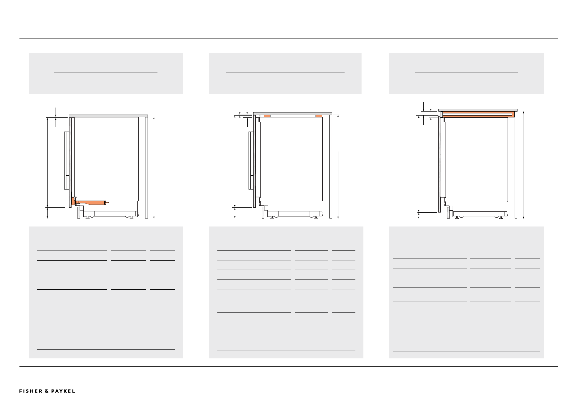
RS2435V2RT1, RS2435V2R1, RS2435SBLT1, RS2435SBL1PLANNING GUIDE | CUSTOM DOOR PANEL OPTIONS
CUSTOM DOOR PANEL
Assisted Opening Accessories
CUSTOM DOOR PANEL
Sub-structure
Multiple installation - ensuring benchtop support
CUSTOM DOOR PANEL
Recessed handle
c
b
d
c
B
d
c
b
d
e
e
Product Dimensions inch mm
A
Cavity height 34 - 35 7/16 864 - 900
B
Maximum door panel height 34 12/16 882
Minimum door panel height 30 761
c
Visual toe kick height 10/16 - 5 15/16 15 - 150
d
Gap between door panel and
bench top
2/16 3
Assisted Opening Accessories Planning Guide
available soon
Product Dimensions inch mm
A
Cavity height* 35 - 36 2/16 888 - 918
b
Maximum door panel height* 35 7/16 900
Minimum door panel height*
30 15/16
785
c
Visual toe kick height 10/16 - 5 15/16 15 - 150
d
Common sub-structure height
12/16
18
e
Gap between door panel and
bench top
2/16 3
*With a 12/16" (18mm) sub-structure
**Adjust door panel template accordingly
Refer to pages 20 & 21 for Panel Templates
Product Dimensions inch
mm
A
Cavity height* 35 13/16 - 37 3/16 909- 945
b
Maximum door panel height* ** 36 8/16 927
Minimum door panel height* ** 32 812
c
Visual toe kick height 10/16 - 5 15/16 15 - 150
d
Clearance between top door
and benchtop
1 6/16 35
e
Sub-structure 1 13/16 45
*With a 1 13/16" (45mm) sub-structure
**Adjust door panel template accordingly
Bench top overhang not recommended for recessed handle
A A
A
<< CONTENTS

© FISHER & PAYKEL LIMITED 2024 PAGE 2390003302B PLANNING GUIDE REFRIGERATION - VERSION B - APRIL 2024
SERVICES
IMPORTANT NOTE: Throughout this guide, dimensions may vary by ±2mm
(1/16''). Please read the Installation Guide for detailed information on
installing the product. For full installation instructions visit fisherpaykel.com
PAGE 2490003302B PLANNING GUIDE REFRIGERATION - VERSION B - APRIL 2024 © FISHER & PAYKEL LIMITED 2024
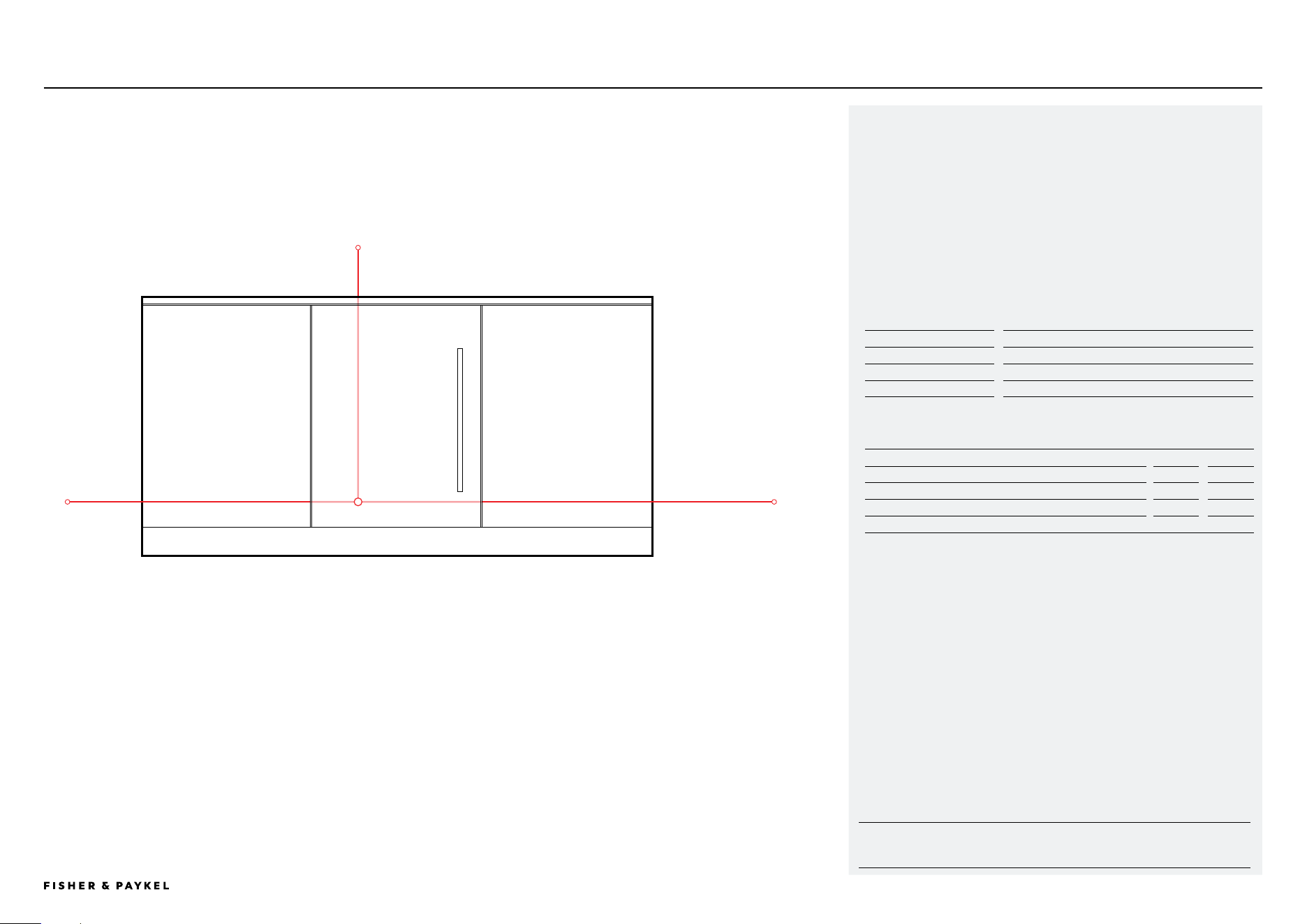
RS2435V2RT1, RS2435V2R1, RS2435SBLT1, RS2435SBL1PLANNING GUIDE | SERVICES
POWER AND WATER CONNECTIONS
Integrated Wine Cabinets &
Integrated Beverage Centres
Model No:
RS2435V2RT1, RS2435V2R1
Integrated Wine Cabinets
RS2435B2LT1, RS2435BL1
Integrated Beverage Centres
Opposite hinge can be achieved using supplied parts.
Please refer to Installation Guide for details.
Electrical Specifications
Supply
115 V, 60 Hz
Service
10 A
NOTE: Recommended that services are routed to the adjacent cabinet.
Cord Lengths Electrical
inch
mm
a Power cord length (from the left edge of the product)*
70 14/16
1800
B Power cord length (from the right edge of the product)*
78 12/16
2000
B Power cord length (from the right edge of the product)*
55 2/16
1400
* Excluding plug.
Recommended that services are located in neighbouring cabinets
<< CONTENTS

© FISHER & PAYKEL LIMITED 2024 PAGE 2590003302B PLANNING GUIDE REFRIGERATION - VERSION B - APRIL 2024
HANDLE DATA SHEETS
IMPORTANT NOTE: Throughout this guide, dimensions may vary by ±2mm
(1/16''). Please read the Installation Guide for detailed information on
installing the product. For full installation instructions visit fisherpaykel.com
PAGE 2690003302B PLANNING GUIDE REFRIGERATION - VERSION B - APRIL 2024 © FISHER & PAYKEL LIMITED 2024
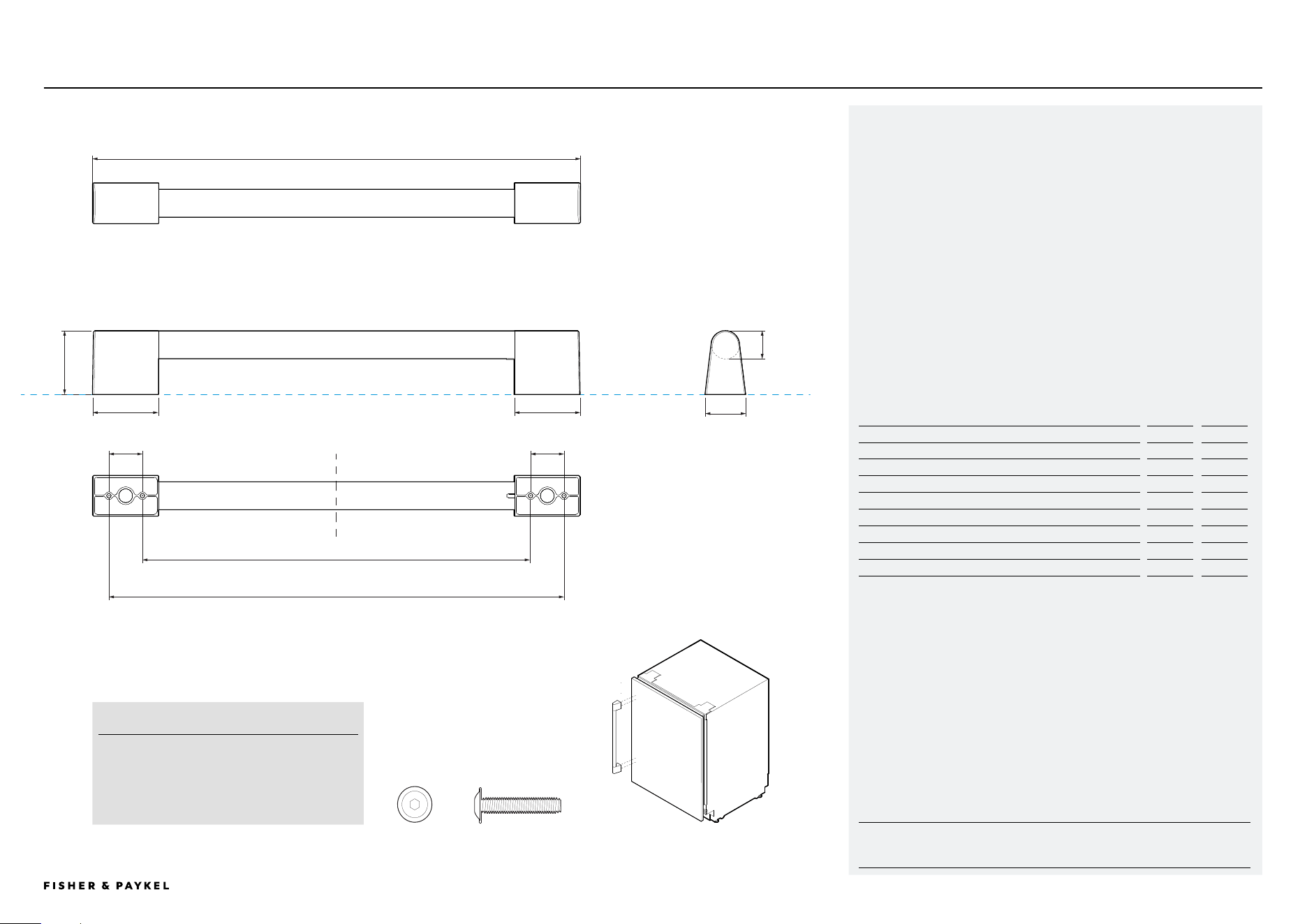
HANDLE DATA SHEET
For all Integrated Wine Cabinet &
Integrated Beverage Center models
Model no:
Professional Handle AHP3RD35
For Models:
RS2435V2RT1, RS2435V2R1
Integrated Wine Cabinets
RS2435SBLT1, RS2435SBL1
Integrated Beverage Centers
Handle Dimensions
inch
mm
a Overall length of handle
17 7/16
442
B Overall height of handle
2 5/16
58
c Overall width of handle
1 7/16
37
D Length of off-stand
2 6/16
60
e Distance between attachment holes
1 3/16
30
f Distance between inner attachment holes
13 15/16
353
g Distance between outer attachment holes
16 4/16
413
h Thickness of handle rail
1
25
RS2435V2RT1, RS2435V2R1, RS2435SBLT1, RS2435SBL1DATA SHEET | PROFESSIONAL HANDLE
SCREWS
M5 X 12" Pan Head Socket Screw (4 per handle)
Suits standard 3/4inch panel. Thicker panels
may require counterboring or longer screws
a
b
d c
g
f
e
d
e
h
<< CONTENTS
IMPORTANT NOTE: Throughout this guide, dimensions may vary by ±2mm
(1/16''). Please read the Installation Guide for detailed information on
installing the product. For full installation instructions visit fisherpaykel.com
PAGE 2790003302B PLANNING GUIDE REFRIGERATION - VERSION B - APRIL 2024 © FISHER & PAYKEL LIMITED 2024
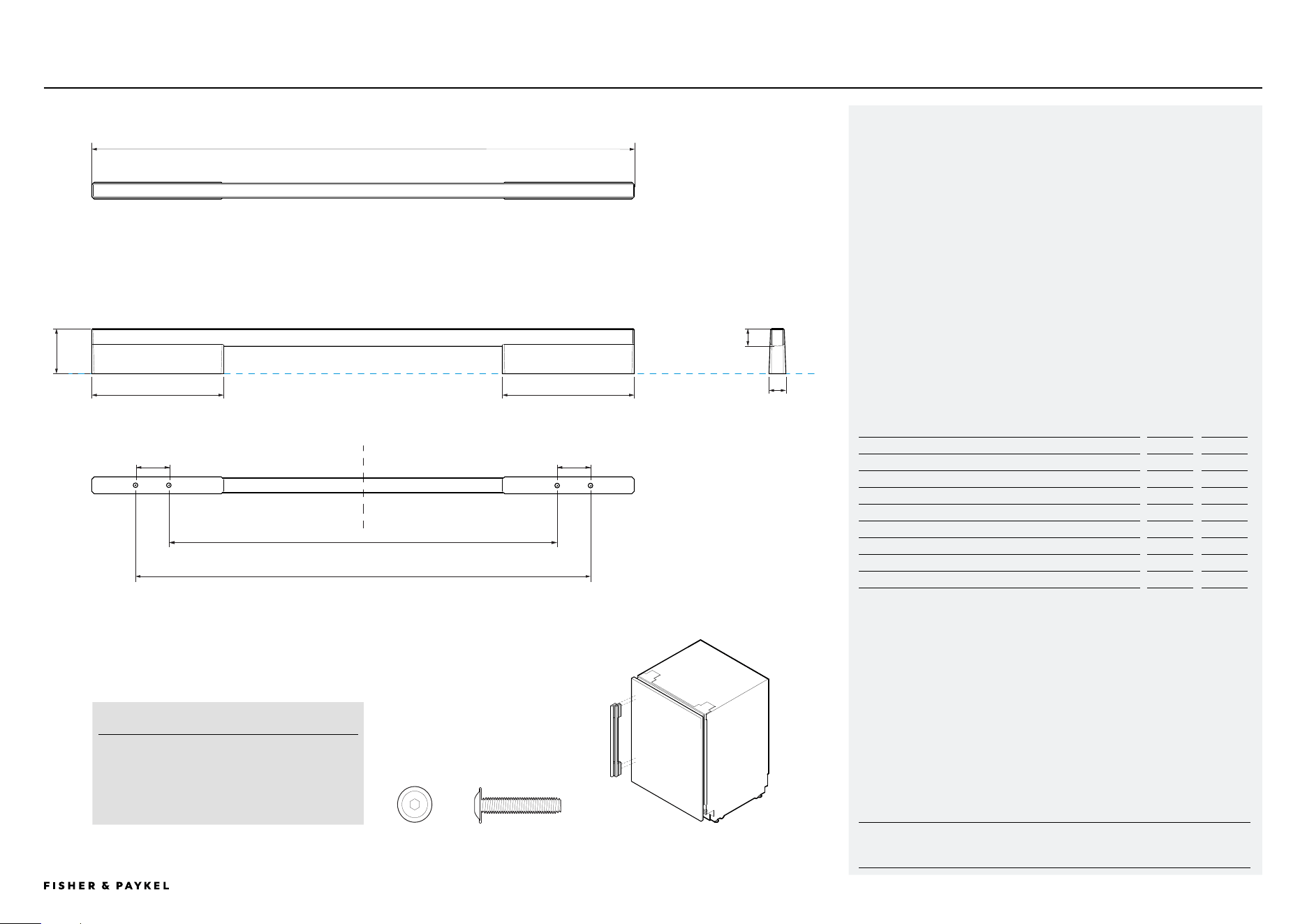
HANDLE DATA SHEET
For all Integrated Wine Cabinet &
Integrated Beverage Center models
Model no:
Fine Aluminium Handle AHD5RD35
Fine Black Aluminium Handle AHD5RD35B
For Models:
RS2435V2RT1, RS2435V2R1
Integrated Wine Cabinets
RS2435SBLT1, RS2435SBL1
Integrated Beverage Centers
Handle Dimensions
inch
mm
a Overall length of handle
19 7/16
493
B Overall height of handle
1 10/16
41
c Overall width of handle
10/16
15
D Length of off-stand
4 12/16
120
e Distance between attachment holes
1 3/16
30
f Distance between inner attachment holes
13 15/16
353
g Distance between outer attachment holes
16 4/16
413
h Thickness of handle rail
10/16
16
RS2435V2RT1, RS2435V2R1, RS2435SBLT1, RS2435SBL1DATA SHEET | FINE ALUMINIUM HANDLE
SCREWS
M5 X 12" Pan Head Socket Screw (4 per handle)
Suits standard 3/4inch panel. Thicker panels
may require counterboring or longer screws
a
b
d c
g
f
e
d
e
h
<< CONTENTS
IMPORTANT NOTE: Throughout this guide, dimensions may vary by ±2mm
(1/16''). Please read the Installation Guide for detailed information on
installing the product. For full installation instructions visit fisherpaykel.com
PAGE 2890003302B PLANNING GUIDE REFRIGERATION - VERSION B - APRIL 2024 © FISHER & PAYKEL LIMITED 2024
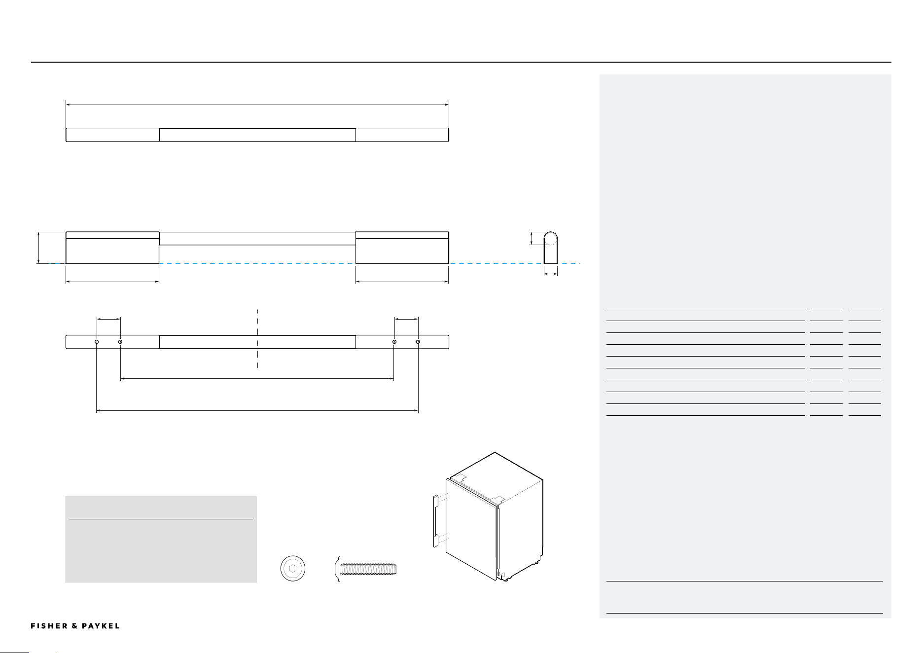
HANDLE DATA SHEET
For all Integrated Wine Cabinet &
Integrated Beverage Center models
Model no:
Fine Round Handle AHSRD35
For Models:
RS2435V2RT1, RS2435V2R1
Integrated Wine Cabinets
RS2435SBLT1, RS2435SBL1
Integrated Beverage Centers
Handle Dimensions
inch
mm
a Overall length of handle
19 7/16
493
B Overall height of handle
1 10/16
41
c Overall width of handle
11/16
17
D Length of off-stand
4 12/16
120
e Distance between attachment holes
1 3/16
30
f Distance between inner attachment holes
13 15/16
353
g Distance between outer attachment holes
16 4/16
413
h Thickness of handle rail
11/16
17
RS2435V2RT1, RS2435V2R1, RS2435SBLT1, RS2435SBL1DATA SHEET | FINE ROUND HANDLE
SCREWS
M5 X 12" Pan Head Socket Screw (4 per handle)
Suits standard 3/4inch panel. Thicker panels
may require counterboring or longer screws
a
b
d
c
g
f
e
d
e
h
<< CONTENTS
IMPORTANT NOTE: Throughout this guide, dimensions may vary by ±2mm
(1/16''). Please read the Installation Guide for detailed information on
installing the product. For full installation instructions visit fisherpaykel.com
PAGE 2990003302B PLANNING GUIDE REFRIGERATION - VERSION B - APRIL 2024 © FISHER & PAYKEL LIMITED 2024
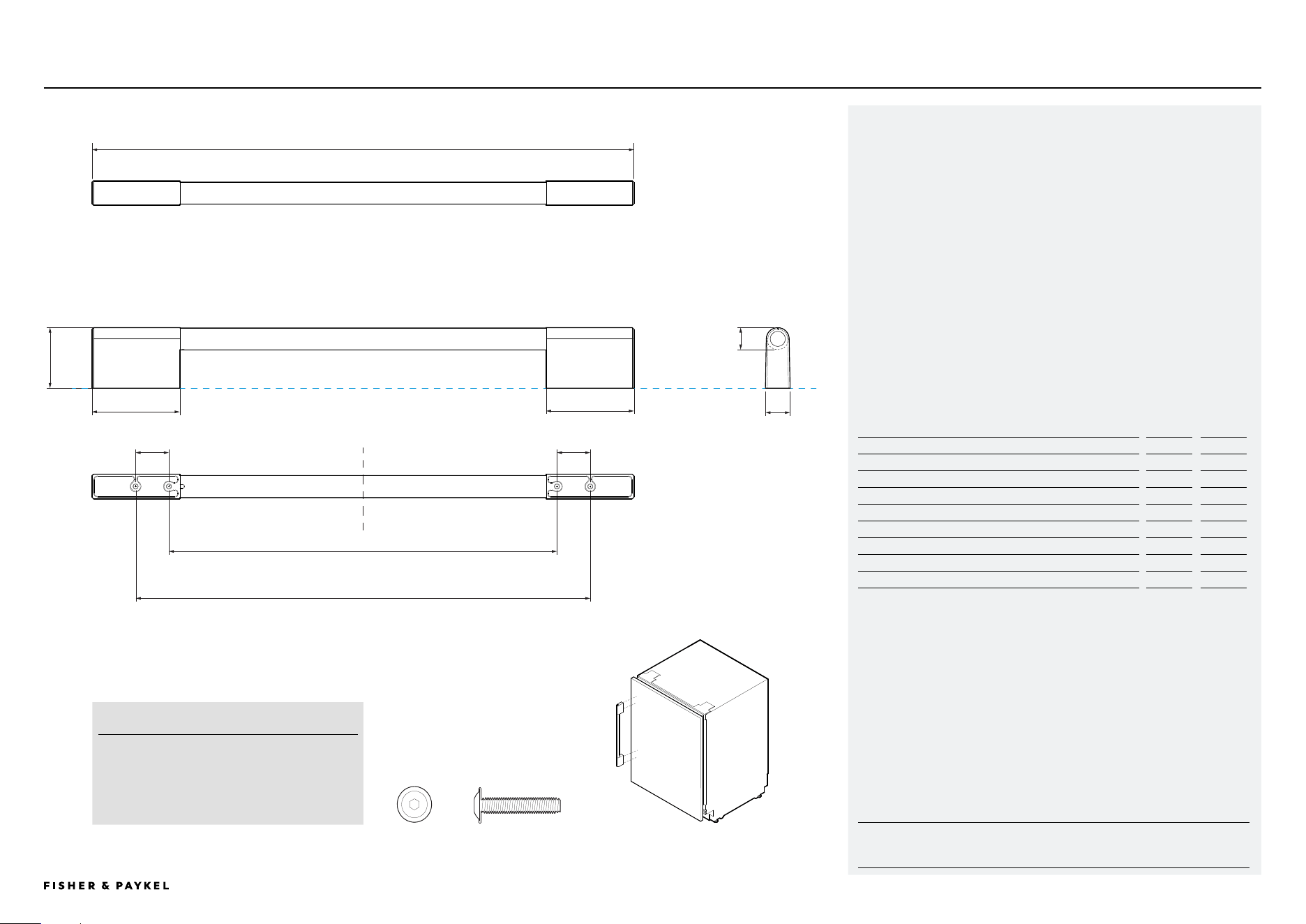
HANDLE DATA SHEET
For all Integrated Wine Cabinet &
Integrated Beverage Center models
Model no:
Classic Handle AHCLRD35
For Models:
RS2435V2RT1, RS2435V2R1
Integrated Wine Cabinets
RS2435SBLT1, RS2435SBL1
Integrated Beverage Centers
Handle Dimensions
inch
mm
a Overall length of handle
16 5/16
414
B Overall height of handle
2 3/16
55
c Overall width of handle
14/16
22
D Length of off-stand
3 3/16
80
e Distance between attachment holes
1 3/16
30
f Distance between inner attachment holes
13 15/16
353
g Distance between outer attachment holes
16 4/16
413
h Thickness of handle rail
13/16
20
RS2435V2RT1, RS2435V2R1, RS2435SBLT1, RS2435SBL1DATA SHEET | CLASSIC HANDLE
SCREWS
M5 X 12" Pan Head Socket Screw (4 per handle)
Suits standard 3/4inch panel. Thicker panels
may require counterboring or longer screws
a
b
d
c
g
f
e
d
e
h
<< CONTENTS

© FISHER & PAYKEL LIMITED 2024 PAGE 3090003302B PLANNING GUIDE REFRIGERATION - VERSION B - APRIL 2024