1
av0823-0/1
PGQP3723ZA
• Before attempting to connect or install this product, please read these instructions carefully
and save this manual for future use.
• The external appearance and other parts shown in this manual may differ from the actual
product within the scope that will not interfere with normal use due to improvement of the
product.
i-PRO Co., Ltd. assumes no responsibility for injuries or property damage
resulting from failures arising out of improper installation or operation
inconsistent with this documentation or through use of parts other than this
product, such as locally procured parts.
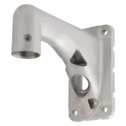
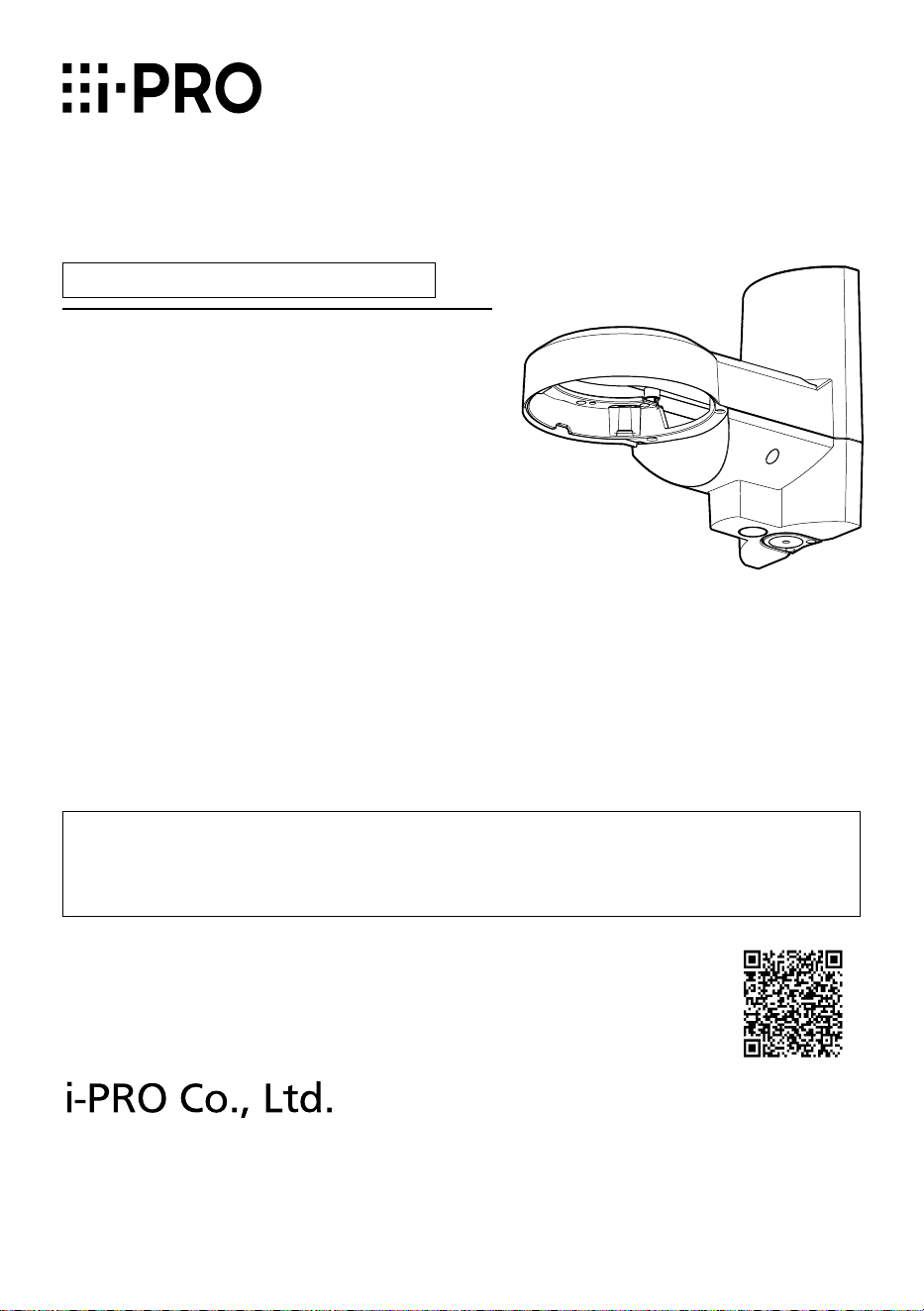
Wall Mount Bracket
Model No. WV-QWL502-W
Installation Guide
© i-PRO Co., Ltd. 2023
https://www.i-pro.com/
Included Installation Instructions
“<Control No.: C****>” used in these documents should be used to search for
information on our technical information website (https://i-pro.com/products_
and_solutions/en/surveillance/learning-and-support/knowledge-base/technical-
information) and will guide you to the right information.

2
Caution:
• Before attempting to connect or operate
this product, please read these instruc-
tions carefully.
Notice:
• This product is not suitable for use in loca-
tions where children are likely to be pres-
ent.
• Do not install this product in locations
where ordinary persons can easily reach.
• For information about screws and other
parts required for installation, refer to the
corresponding section of this document.
Do not hang down from this product or use this product as a pedestal.
Failure to observe this may cause injury or accidents.
Do not use this bracket except with suitable cameras.
Failure to observe this may cause a drop resulting in injury or accidents.
Refer installation work to the dealer.
Installation work requires technique and experience.
Failure to observe this may cause fire, electric shock, injury, or damage to the product.
Be sure to consult the dealer.
The mount bracket that comes with this product shall be used. (Pole mount only)
Failure to observe this may cause a drop resulting in injury or accidents.
Use only the mount bracket that comes with this product for installation.
The screws and bolts must be tightened to the specied torque.
Failure to observe this may cause a drop resulting in injury or accidents.
Install the product accurately and securely on the installation surface or pole in
accordance with the installation instructions.
Failure to observe this may cause injury or accidents.
Do not rub the edges of metal parts with your hand.
Failure to observe this may cause injury.
When using this product, also read the “Precautions” described in the operating
instructions for the camera to be attached.
Precautions
3
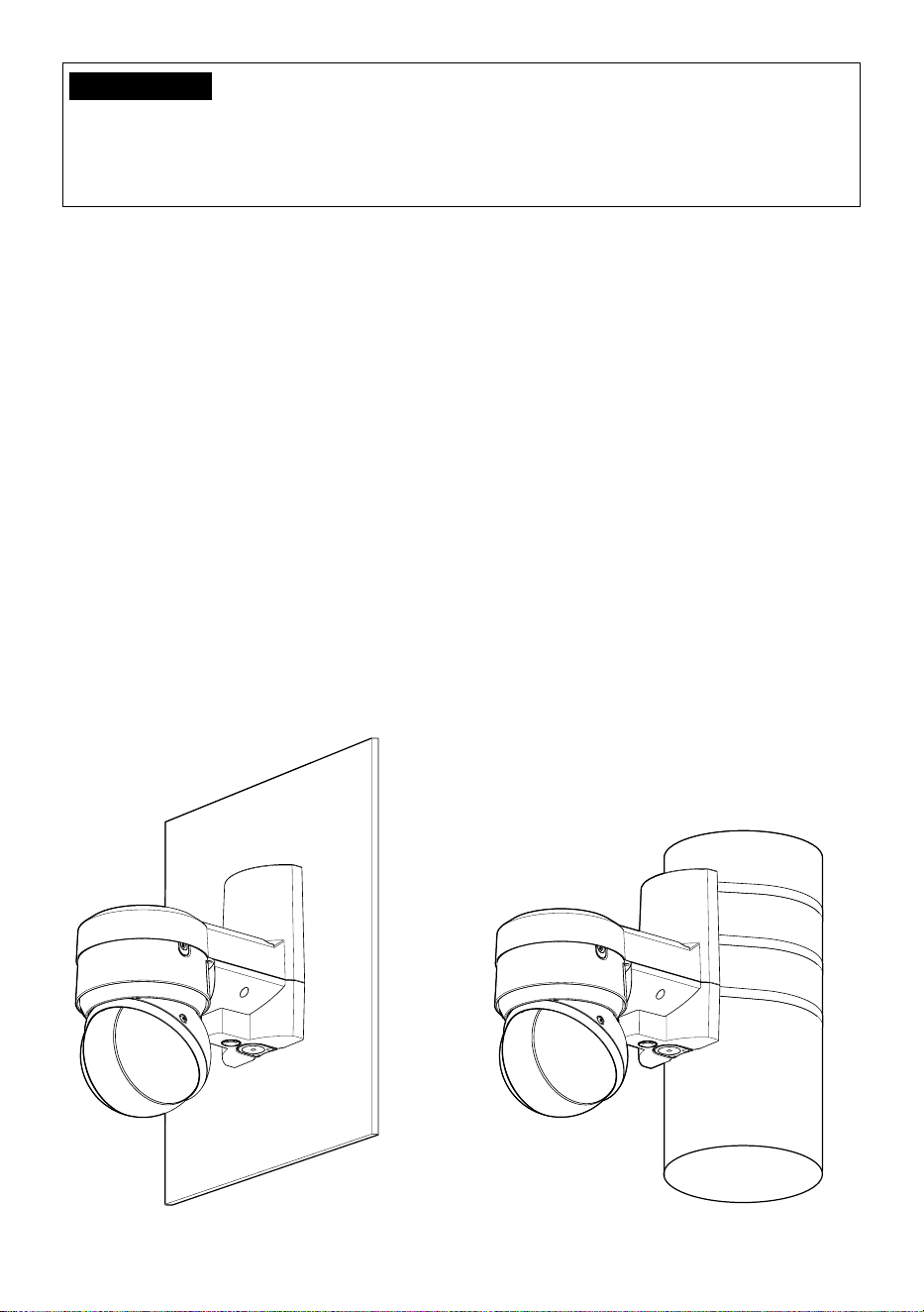
Preface
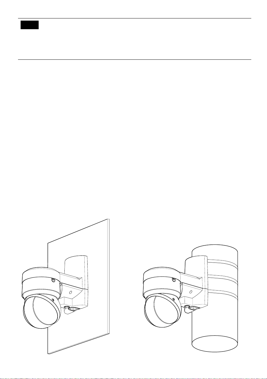
This product is a Wall Mount Bracket that is designed to mount the network camera on a wall
or a vertical round pole.
The latest information about the supported cameras <Control No.: C0501>
Ambient operating temperature:
–50 °C to +60 °C {–58 °F to +140 °F}
Dimensions: 166 mm (W) x 230 mm (H) x 287 mm (D)
{6-17/32 inches (W) x 9-1/16 inches (H) x 11-5/16 inches (D)}
Mass: Approx. 2.1 kg {4.64 lbs}
(including fixing bands 170 g {0.38 lbs})
Finish: Aluminum die cast / PC resin i-PRO white
Specifications
In order to prevent injury, this product must be securely mounted to the installation
surface or pole according to Installation Guide.
About installable pole
• Please consider the influence of vibration and wind at the installation site and mount the
bracket onto the poles with appropriate strength.
Installable pole: round (ø80 mm to ø200 mm {ø3-5/32 inches to ø7-7/8 inches})
• Please do not mount it onto a pole made of wood or resin with low endurance or quality hav-
ing changed after experiencing years' time.
• After the bracket is mounted, please verify the following content once a year. In the event of
abnormality, please inform the dealer or the constructor.
・Do not allow any slanting, distortion or offset in installation.
・Bracket and fixing band should not have any serious rust or damage.
About the installation methods
• The bracket is specifically designed for installation onto a round pole.
• Fix the bracket to a pole by tightening the screws of three fixing bands. Please make sure to
fix firmly with the following tightening torque.
(Recommended tightening torque: 5 N·m {3.69 lbf·ft})
Precautions for installation
4
• For the pole, install the fixing band vertically. A slanted installation of the fixing band will result
in excessive slack which could lead to a fall.
• When installing, please pay attention to not damage any part that influences the strength of
the fixing band.
• When the pole mount bracket is installed to a pole with easy gliding painting or coating,
please pay attention to rotating and sliding down.
• After the installation is finished, please check if there are deviations related to slackness, fit-
ting and rotation of the fixing band. In the event of abnormality, please tighten again.
Check before the installation.
Once the bracket is installed with a deformed mount bracket and/or damaged part, it could
potentially fall. Before the installation, please make sure to check the appearance of the bracket
and the fixing band.
Screw tightening
• Make sure to tighten the screws that fix camera onto this product.
• Do not use an impact driver. Use of an impact driver may damage the screws or cause tight-
ening excessively.
• When a screw is tightened, make the screw at a right angle to the surface. After tightening
the screws or bolts, perform checks to ensure that the tightening is sufficient enough so that
there is no movement or looseness.
Make sure to remove this product if it will no longer be used.
<Wall>
<Vertical round pole>
IMPORTANT
Please do not exceed the torque limit when tightening the screw. Excessive tightening
may damage the screw of the fixing band. Please do not use a fixing band with dam-
aged tightening screw.
Limited tightening torque: 7.5 N·m {5.53 lbf·ft}
5
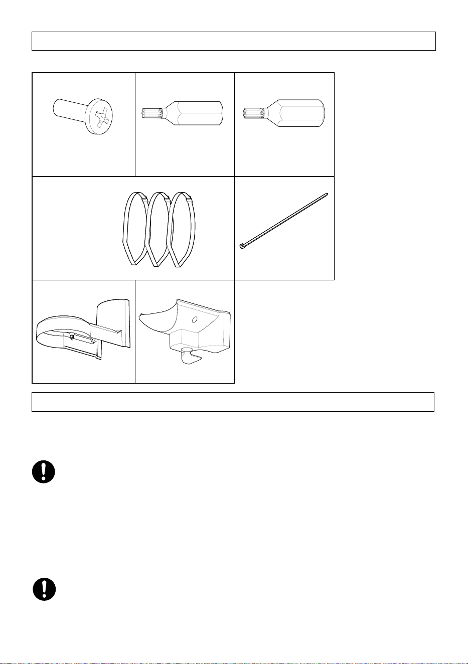
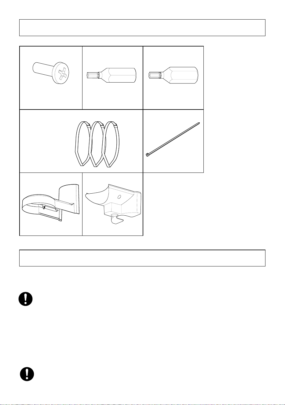
Standard Accessories
Fixing screw
for microphone unit 3x
(of them, 1 for spare)
Bit 1x (Hex wrench,
screw size 6.35 mm
{1/4 inches} T20)
Bit 1x (Hex wrench,
screw size 6.35 mm
{1/4 inches} T10)
Fixing bands 3x
Support band 1x
Top cover 1x
Bottom cover 1x
Other items that are needed (not included)
When installing the wall
・Fixing screw (M10) or anchor...............................4 pcs.
When installing the pole
・Torque wrench....................................................1 pc.
・Gloves................................................................1 pair
• Minimum pullout strength: 823 N {185 lbf} (per 1 pc.)
• Refer to our support website <Control No.: C0120>) for information on the minimum
pull-out strength.
• Select screws according to the material of the location that the camera will be mounted to.
In this case, wood screws and nails should not be used.
• In order to tighten the fixing bands during installation, it's necessary to use torque
wrench (locally procured).
• Please wear gloves during installation. Cutting off fixing bands may cut your fingers.

6
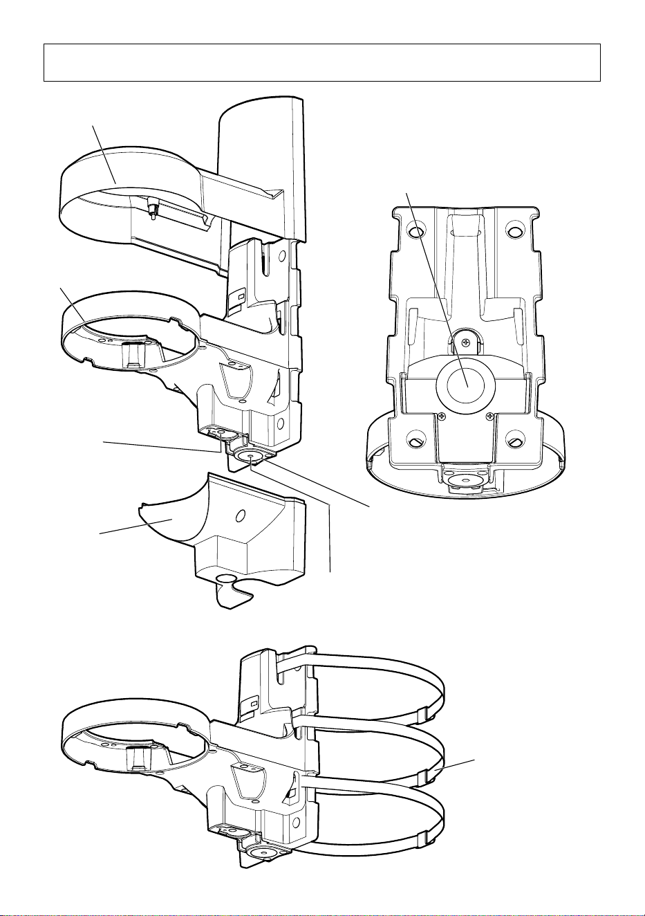
Parts and functions
Top cover
(accessory)
Wall mount bracket
Microphone Unit
mounting position
(WV-PM500 : optional
accessory)
Bottom cover
(accessory)
Cable cap
Cable access hole (rear)
The female thread for conduit is
compliant with ANSI NPSM (parallel
pipe threads) 3/4 or ISO 228-1
(parallel pipe threads) G3/4.
Cap for the female thread for
the conduit
Fixing band
(accessory)
7
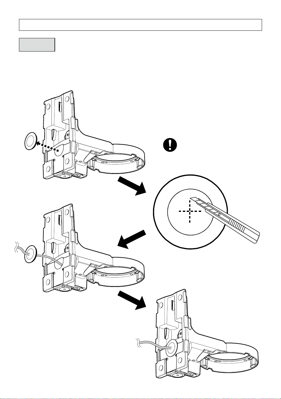
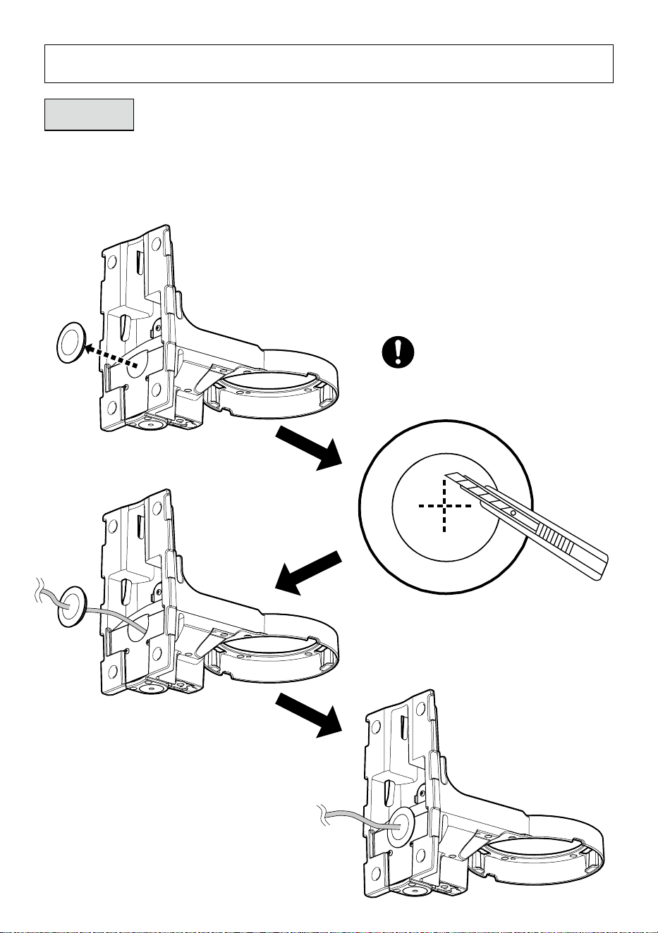
Installation
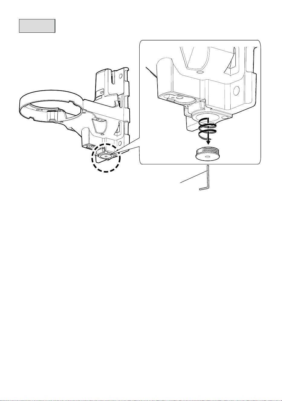
Step 1
Preparations
■
When wiring backwards
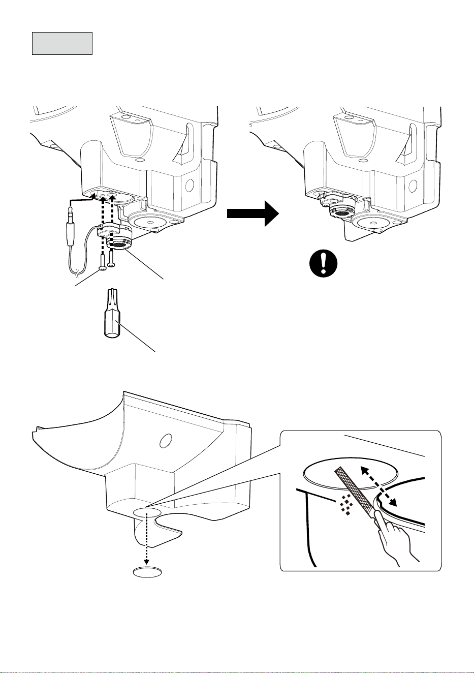
Note:
When wiring downward using a conduit, leave the cable
cap attached to this product.
Make a slit in the center of the cable cap
with a cutter.
8
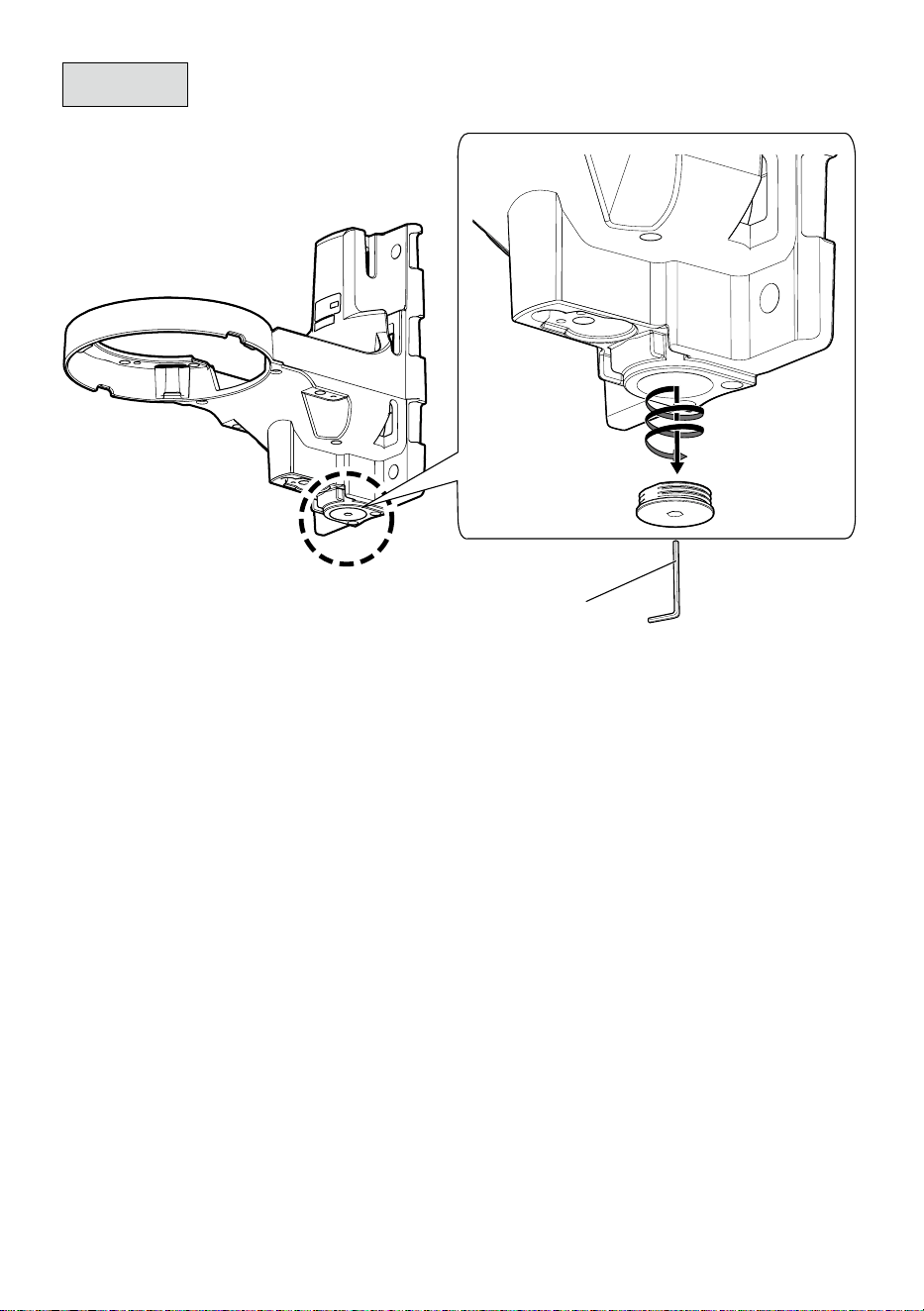
Step 1
Preparations (Continued)
■
When wiring downward
5 mm {3/16 inches}
hexagon wrench
(locally procured)
9
Step 1
Preparations (Continued)
■
When using a Microphone Unit
①
②
Bit T10
(accessory)
Microphone Unit
(WV-PM500 : optional
accessory)
Recommended tightening torque:
0.78 N·m {0.58 lbf·ft}
Fixing screw
for microphone
unit (2 pcs.)
(M3 : accessory)
10
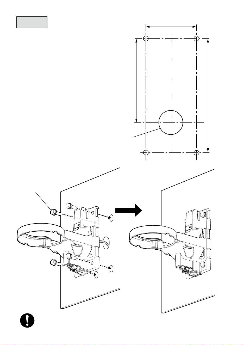
80 mm
Hole for cable
installation: ø38 mm
{ø1-1/2 inches}
{3-5/32 inches}
133 mm
180 mm
{7-3/32 inches}
{5-1/4 inches}
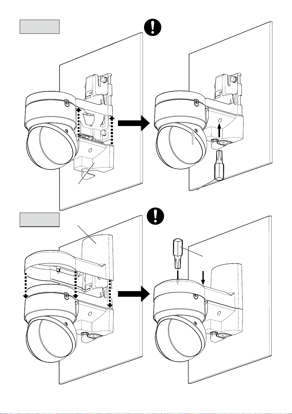
Step 2
■
When installing on the wall
Fixing screw (4 pcs.)
(M10 : locally procured)
Minimum pull-out strength:
823 N {185 lbf} /per 1 pc.
Note:
For wall installation, do not use the attached
fixing bands.

11
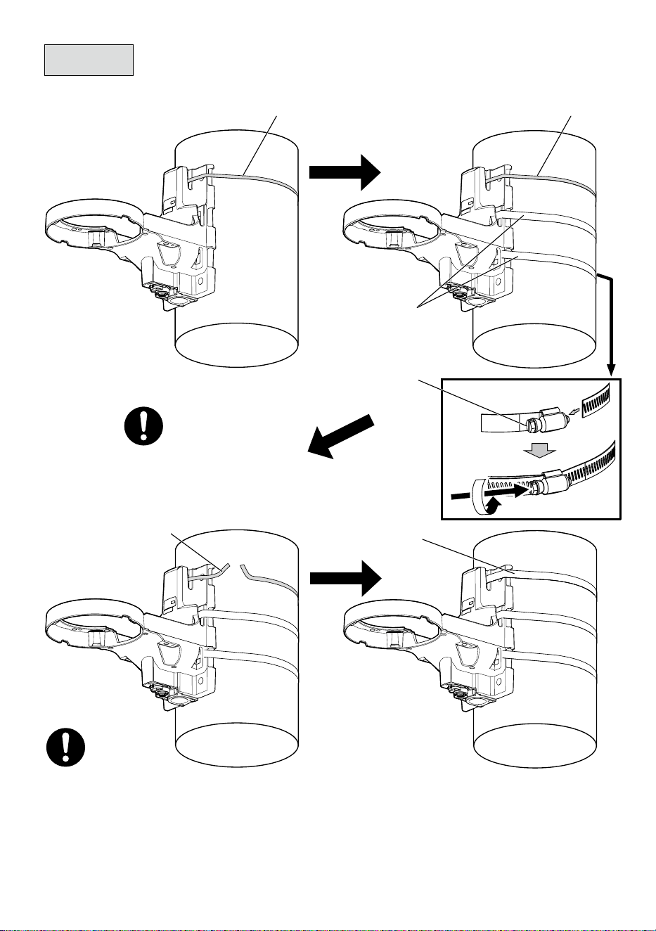
Step 2
(Continued)
■
When installing on a pole
Support band
(accessory)
Support band
(accessory)
Support band
(accessory)
Fixing band (2 pcs.)
(accessory)
Fixing band (1 pcs.)
(accessory)
Fixing band lock
screw
Fixing band lock screw
Recommended tightening torque:
(5 N·m {3.69 lbf·ft})
• During installation, please rotate fixing band to adjust its position and make sure the fixing
band lock screw is located on the surface of the pole.
• During installation, please note that the cable is not placed between the fixing bands and
the pole.
• For the remaining part of fixing bands, leave approximate 30 mm to 70 mm {1-3/16 inches
to 2-3/4 inches} in the part of fixing band lock screw and use a tool (locally procured) to cut
off the remaining part. Please treat the cut-off part to prevent injury.
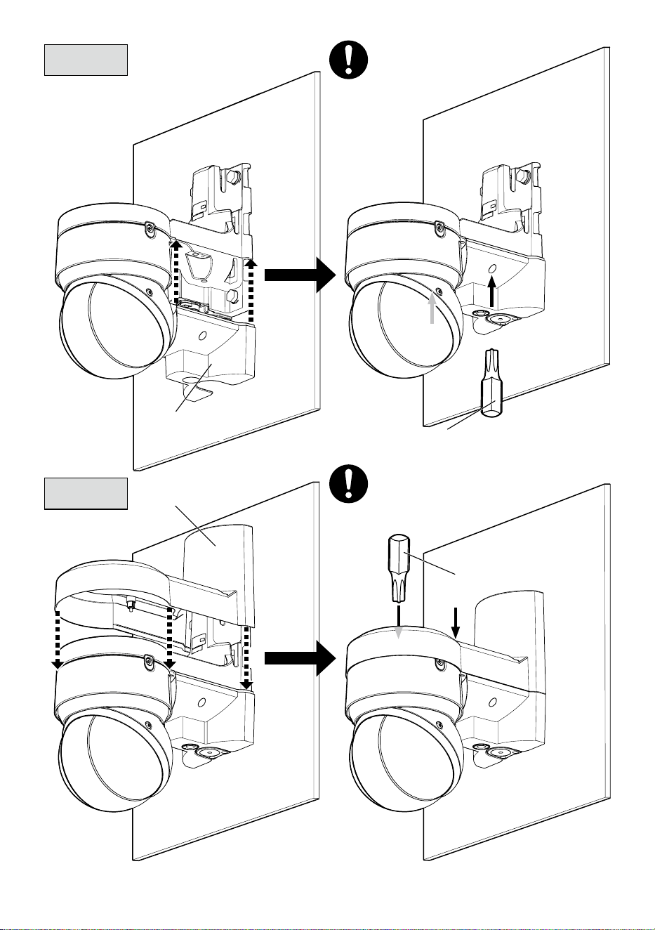
12
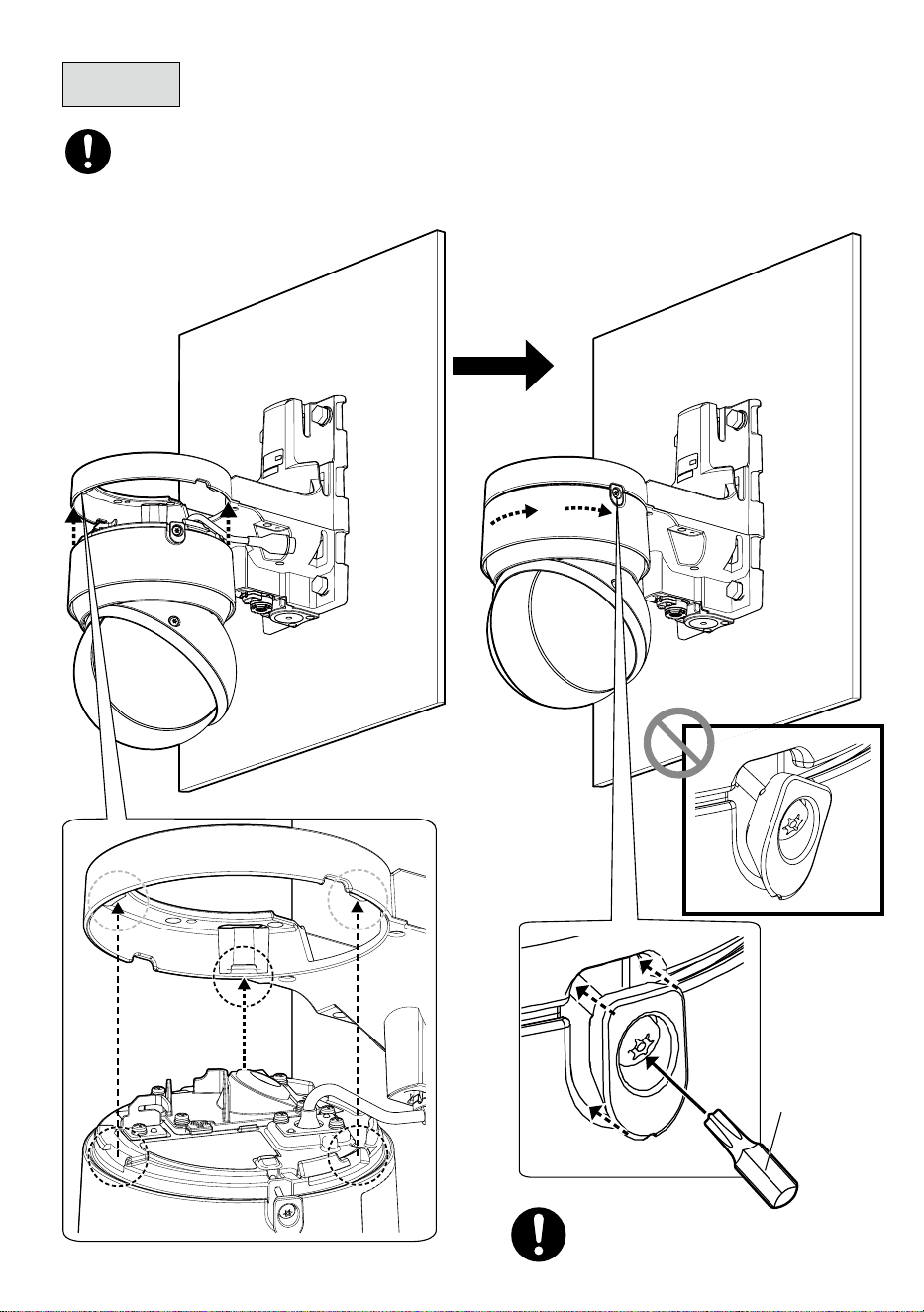
Step 3
Bit T20
(accessory)
Recommended tightening torque:
0.78 N·m {0.58 lbf·ft}
• Before temporarily securing the camera to the bracket, remove the tape securing the
left and right wedge sections and ensure that the threads are not caught.
13
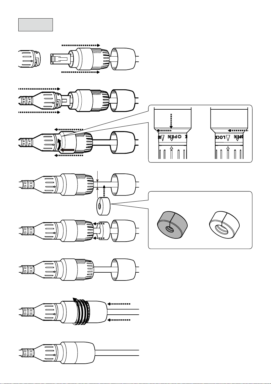
Step 4
➡➡
➡➡➡➡
➡
➡
Waterproof rubber A
D : ø5 mm to ø7 mm
{ø3/16 to ø9/32 inches}
D : ø7 mm to ø8.5 mm
{ø9/32 to ø11/32 inches}
Waterproof rubber B
D
■
RJ45 waterproof connector
* If necessary, reinforce waterproofing with
waterproof tape (camera accessory). Please note that
using waterproof tape may make wiring difficult.
14
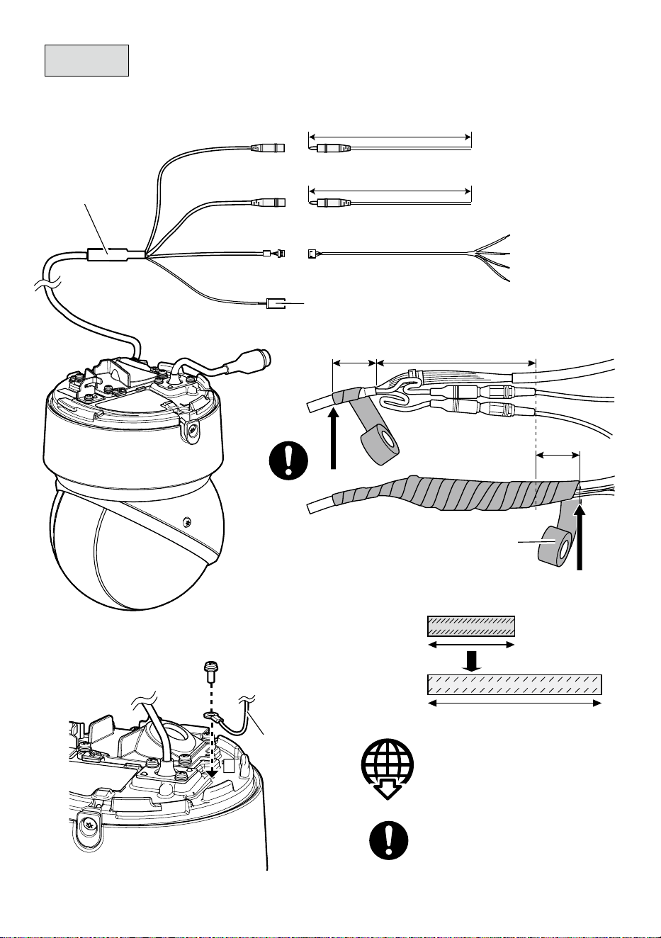
Approx. 20 mm
{25/32 inches}
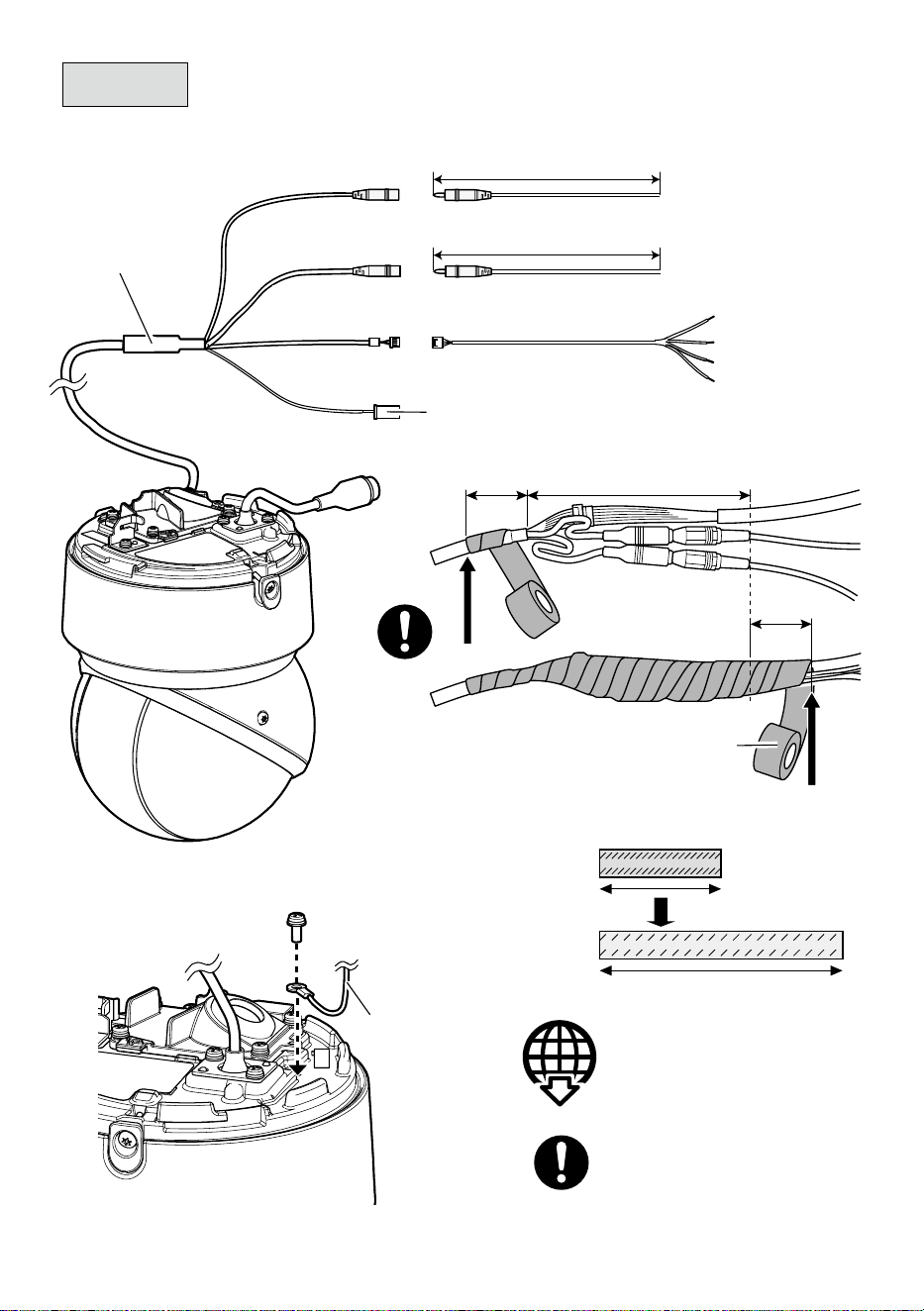
Step 5
■
When using an I/O cable
I/O cable
WV-QCA501A
(optional accessory)
■
Ground wire
Audio in (White)
Audio out (Black)
EXT I/O
< 1 m {3.28 feet} (Mic)
< 10 m {32.8 feet} (Line)
< 10 m {32.8 feet}
4P alarm cable
(WV-QCA501A accessory)
GND (Black)
ALARM IN3 (Gray)
ALARM IN2 (Red)
ALARM IN1 (Green)
• This cable is not to be used. Apply
waterproofing also to this cable as
well as other cables.
Technical information website
“Countermeasure for Lightning Surge”
<Control No.:C0121>
Ground wire
(locally procured)
Recommended tightening torque:
0.78 N·m {0.58 lbf·ft}
Approx. 20 mm
{25/32 inches}
Waterproof tape
(WV-QCA501A accessory)
Stretch the waterproof tape by
about twice the length to use.
110 mm {4-11/32 inches} or less
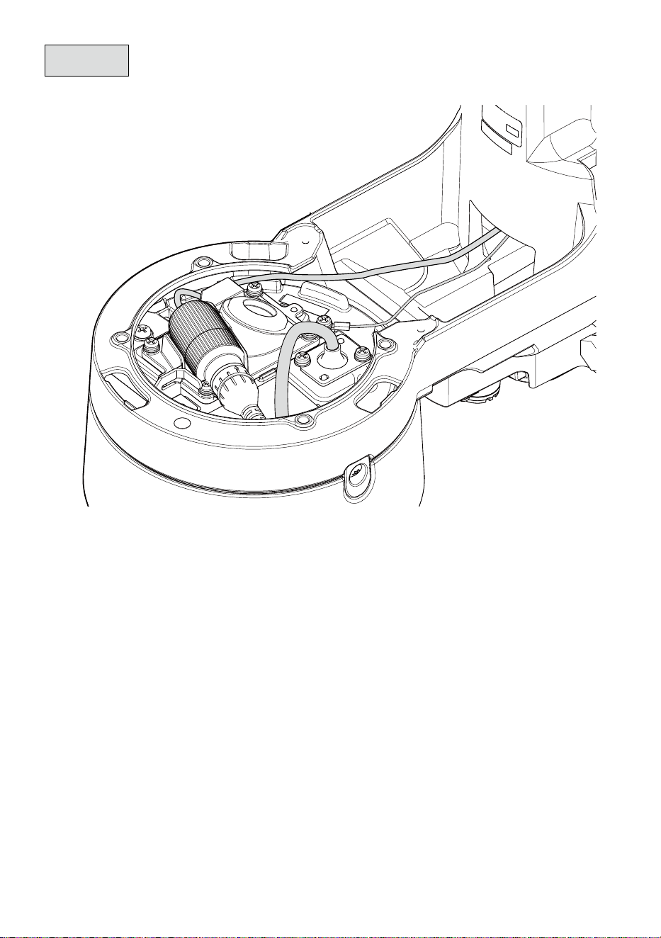
15
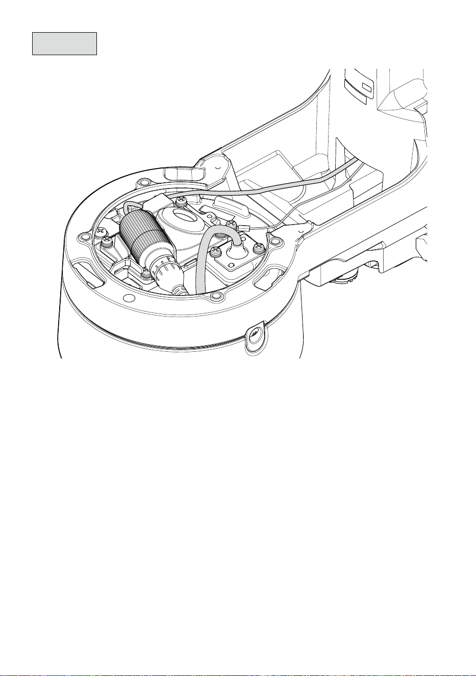
Step 6
Wiring example when connecting only RJ45 network cable
16
Recommended tightening torque:
0.78 N·m {0.58 lbf·ft}
Step 7
Step 8
Bottom cover
(accessory)
Top cover
(accessory)
Bit T20
(accessory)
Bit T20
(accessory)
Recommended tightening torque:
0.78 N·m {0.58 lbf·ft}
17
取扱説明書
工事説明付き
カメラ壁取付金具
品番
WV-QWL502-W
このたびは、弊社製品をお買い上げいただき、まことにありがとうございます。
取扱説明書をよくお読みのうえ、正しく安全にお使いください。
ご使用前に「安全上のご注意」を必ずお読みください。
この取扱説明書は大切に保存してください。
製品の改良などにより、ご使用上影響のない範囲で、記載されている外観などが実際の
製品と異なる場合があります。
設置ガイド
取扱説明書に記載されていない方法や、指定の部品を使用しない方法で施工されたこ
と、および現地調達の部品など本機以外の要因により事故や損害が生じたときには、
当社では責任を負えません。また、その施工が原因で故障が生じた場合は、製品保証
の対象外となります。
i-PRO製品の「お問い合わせ」については、以下の弊社サポートウェブ
サイトを参照してください。
https://i-pro.com/products_and_solutions/ja/surveillance/contact-us
※「日本エリア」でお使いの場合に限ります。日本以外でお使いの場合の
サービスはいたしかねます。
取扱説明書に記載されている「<管理番号:Cxxxx>」は、以下の弊社技
術情報ウェブサイト内で該当する情報を検索する際に使用する番号です。
https://i-pro.com/products_and_solutions/ja/surveillance/learning-and-
support/knowledge-base/technical-information
https://www.i-pro.com/
18
警告
■ぶら下がらない。足場代わりにしない
(けがや事故の原因となります。)
■専用のカメラ以外は取り付けない
(落下によるけがや事故の原因となります)
■工事は販売店に依頼する
(工事には技術と経験が必要です。火災、感電、けが、器物損壊の原因となります。)
⇒ 必ず販売店に依頼してください。
■付属の取付金具を使用する(ポール設置時のみ)
(落下によるけがや事故の原因となります。)
⇒ 設置の際は、付属の取付金具を使用してください。
■ねじやボルトは指定されたトルクで締め付ける
(落下によるけがや事故の原因となります。)
■設置の説明にしたがって設置面またはポールにしっかり取り付ける
(けがや事故の原因となります。)
注意
■金属のエッジで手をこすらない
(強くこするとけがの原因となります。)
本金具をご使用の際は、取り付けるカメラの取扱説明書に記載された「安全上のご
注意」とあわせてお読みください。
安全上のご注意
必ずお守りください
■お守りいただく内容を次の図記号で説明しています。(次は図記号の例です)
人への危害、財産の損害を防止するため、必ずお守りいただくことを説明しています。
■誤った使い方をしたときに生じる危害や損害の程度を区分して、説明しています。
してはいけない内容です。
実行しなければならない内容
です。
注意:
取扱説明書をよくお読みのうえ、正しく安全にお使いください。
注記:
本金具は子供がいる可能性のある場所での使用には適していません。
一般の人が容易に触れることができる場所への設置はしないでください。
設置に必要なねじやそのほかの部材などの情報については本書の該当部分を参照してください。
「死亡や重傷を負うおそ
れがある内容」です。
警告
注意
「
軽傷を負うことや、財産の損害が
発生するおそれがある内容」です。
19
商品概要
本金具はカメラ壁取付金具です。カメラを壁面に取り付けたり、ポールに固定して使用す
る際に使用します。
取り付け可能なカメラの最新情報 <管理番号:C0501>
仕様
使用温度範囲−50 ℃〜+60 ℃
寸法幅:166 mm/高さ:230 mm/奥行き:287 mm
質量約 2.1 kg (固定用バンド170 gを含む)
仕上げアルミダイカスト/PC樹脂 i-PROホワイト
設置上のお願い
■設置工事は電気設備技術基準に従って実施してください。
本金具の設置・接続を始める前に必要な周辺機器やケーブルを確認し、準備してください。
接続する前に、カメラ、PCなど接続する機器の電源を切ってください。
■傷害防止のため、本金具は、設置の説明に従って設置面またはポールにしっか
りと取り付ける必要があります。
■取り付け可能なポールについて
本金具は、設置場所の振動・風などの影響を考慮し、必要な強度を有するポールに取り
付けてください。
取り付け可能なポール:丸形状 ポール(ø80 mm〜ø200 mm)
強度不足や経年変化のある木材や樹脂ポールなどには取り付けないでください。
本金具を設置後は1年に1回をめやすに、以下の内容についてご確認ください。異常が発
見された場合は販売店または施工業者にご連絡ください。
・取り付け状態が傾いたり、ゆがんだり、ずれたりしていないこと。
・本金具および固定用バンドの破損や、著しい錆びなどが発生していないこと。
■ポールへの取り付け方法について
本金具は丸いポールへの取り付け専用金具です。
本金具はポールへ3本の固定用バンドの締付ねじを締め付けて固定します。必ず下記の
締め付けトルクを確保し、確実に固定してください。
推奨締付トルク:5 N・m{51.0 kgf・cm}
20
ねじを限界トルク以上で締めないで下さい。絞め過ぎの場合は固定用バンドの締付ねじ
が破損する場合があります。締付ねじが破損した固定用バンドは使用しないでください。
限界締付トルク:7.5 N・m{76.5 kgf・cm}
固定用バンドはポールに対して垂直に取り付けてください。固定用バンドを傾けて取り
付けると、緩みが発生し落下の原因となります。
設置時に固定用バンドの強度に影響がある部分には傷が入らないようにご注意くださ
い。
滑りやすい塗装やコーティングされたポールに取付ける場合は、回転ずれに注意して取
り付けて下さい。
取付完了後、固定用バンドの緩み・ガタつき・回転ずれなどがないことを確認してくだ
さい。異常がある場合は増し締めを行ってください。
■設置前にご確認ください
変形した取付金具・損傷した部品を使って本金具を設置すると、落下の危険性があります。
設置開始前に本金具および固定用バンドの外観を必ずご確認ください。
■取付ねじの締め付けについて
カメラを本金具に固定するねじは、しっかりと締め付けてください。
インパクトドライバーは使用しないでください。ねじの破損の原因となります。
ねじはまっすぐ締めてください。締めたあとは、目視にて、ガタつきがなく、しっかり
と締められていることを確認してください。
■本金具を使用しなくなった場合は放置せず、必ず撤去してください。
重要
<壁面>
<ポール>
21
付属品をご確認ください
マイクユニット用
固定ねじ x3
(うち1本は予備)
ビット(六角対辺
6.35mm T20) x1
ビット(六角対辺
6.35mm T10) x1
固定用バンド x3補助バンド x1
上カバーx1下カバー x1
付属品以外に必要なもの
■壁面に設置する場合
・固定ねじ(M10)またはアンカー .......................4本
■ポールに設置する場合
・トルクレンチ .........................................................1本
・手袋などの防護具 .................................................1組
最低引抜強度・・・823 N{84 kgf}/1本あたり
最低引抜強度の考え方については弊社技術情報ウェブサイト<管理番号:
C0120>を参照してください。
ねじの種類は取付場所の材質に合わせて選択してください。木ねじおよびくぎは
使用しないでください。
トルクレンチは、固定用バンドを締め付けるために必要です。
設置作業時は、手袋などの防護具をして作業してください。バンド切断部などで
手指を切る原因となります。
22
各部の名前
上カバー
(付属品)
壁取付金具
マイクユニット取付
位置
(WV-PM500:別売り)
下カバー
(付属品)
接続管ケーブル通し穴
JIS C 8305(電線管ねじ)のCTG22
または
JIS B 0202(管用平行ねじ)のG3/4
接続管用めねじキャップ
ケーブルキャップ
ケーブル通し穴 (後)
固定用バンド
(付属品)
23
設置する
Step1
前準備
■後面へ配線する場合
メモ:
接続管を使って下方向へ配線する場合は、ケーブルキャップは、
本金具に付けたままでご使用ください。
ケーブルキャップの中央部に
カッターで切り込みを入れます。
24
Step1
前準備(つづき)
■下方向へ配線する場合
対辺5 mmの六角レンチ
(現地調達)

25
Step1
前準備(つづき)
■外部マイクを使用する場合
ビットT10
(付属品)
推奨締付トルク
0.78 N・m{8.0 kgf・cm}
①
②
マイクユニット
(WV-PM500:別売り)
マイクユニット用
固定ねじ(2本)
(M3:付属品)

26
80 mm
ケーブル通し穴
(
ø38 mm
)
133 mm
180 mm
Step2
■壁面に設置する場合
固定ねじ(4本)
(M10:現地調達)
最低引抜強度:
823 N{84 kgf}(1本あたり)
メモ:
壁面設置の場合は、付属の固定用バンド
は使用しません。
27
■ポールに設置する場合
Step2
(つづき)
固定用バンド締付ねじ
推奨締付トルク:
(5 N・m{51.0 kgf・cm})
取り付け時、固定用バンド締付ねじ部分がポールに接する位置になるように固定用バンド
を回して位置を調整してください。
本金具の固定用バンド通し穴に固定用バンドを通した時、ケーブルが固定用バンドとポー
ルの間に挟まれないように注意してください。
固定用バンドのあまり部分は、工具(現地調達)を使って固定用バンド締付ねじ頭の部分
から約30 mm〜70 mm残して切断し、怪我をしないように切断部を処理してください。
補助バンド
(付属品)
補助バンド
(付属品)
固定用バンド
(2本)(付属品)
補助バンド
(付属品)
固定用バンド
(1本)(付属品)
固定用バンド
締付ねじ

28
Step3
ビット
T20
(付属品)
推奨締付トルク
0.78 N・m{8.0 kgf・cm}
カメラを金具に仮固定する前に、左右のウェッジ部分を固定しているテープを剥
がし、ねじ山がかかっていないことを確認してください。

29
■RJ45防水コネクター
➡➡
➡➡➡➡
➡
➡
防水ラバーA
D: ø5 mm〜
ø7 mm
D: ø7 mm〜
ø8.5 mm
防水ラバーB
D
Step4
※必要ならば防水テープ(カメラ付属品)を
使って防水を補強してください。防水テープを
使用すると配線処理がしにくくなることが
ありますのでご注意ください。
30
Step5
■マルチケーブルを使用する場合
Audio in(白)
Audio OUT(黒)
EXT I/O
< 1 m(Mic)
< 10 m(Line)
< 10 m
4Pアラームケーブル
(WV-QCA501UX付属品)
GND(黒)
ALARM IN3(灰)
ALARM IN2(赤)
ALARM IN1(緑)
このケーブルは使用しません。
ほかのケーブルと一緒に防水処理してください。
マルチケーブル
WV-QCA501UX
(別売り)
約20 mm
約20 mm
防水テープ(WV-QCA501UX付属品)
■アース線接続
防水テープは約2倍に
伸ばして使用する
技術情報ウェブサイト
「雷サージ対策について」
<管理番号:C0121>
推奨締付トルク
0.78 N・m{8.0 kgf・cm}
アース線
(現地調達)
110 mm以下
31
Step6
RJ45ネットワークケーブルのみを接続する場合の配線例
32
推奨締付トルク
0.78 N・m{8.0 kgf・cm}
推奨締付トルク
0.78 N・m{8.0 kgf・cm}
Step7
Step8
ビットT20
(付属品)
ビットT20
(付属品)
上カバー(付属品)
下カバー(付属品)