* Seagate Rescue Data Recovery Services plan is only offered in
selected regions only. Please check with reseller on availability.
201370100, Rev. G
February 2023
Standard models
ST8000VX009
ST6000VX008
ST4000VX015
ST3000VX014
ST2000VX016
ST1000VX012
ST1000VX013
+Rescue Models
*
ST8000VX010
ST6000VX009
ST4000VX016
ST3000VX015
ST2000VX017
SATA Product Manual

© 2023 Seagate Technology LLC. All rights reserved.
Publication number: 201370100, Rev. G February 2023
Seagate, Seagate Technology and the Spiral logo are registered trademarks of Seagate Technology LLC in the United States and/or other countries. SkyHawk and SeaTools are either trade-
marks or registered trademarks of Seagate Technology LLC or one of its affiliated companies in the United States and/or other countries. All other trademarks or registered trademarks are
the property of their respective owners.
No part of this publication may be reproduced in any form without written permission of Seagate Technology LLC.
Call 877-PUB-TEK1(877-782-8351) to request permission.
When referring to drive capacity, one gigabyte, or GB, equals one billion bytes and one terabyte, or TB, equals one trillion bytes. Your computer’s operating system may use a different
standard of measurement and report a lower capacity. In addition, some of the listed capacity is used for formatting and other functions, and thus will not be available for data storage.
Actual quantities will vary based on various factors, including file size, file format, features and application software. Actual data rates may vary depending on operating environment and
other factors. The export or re-export of hardware or software containing encryption may be regulated by the U.S. Department of Commerce, Bureau of Industry and Security (for more
information, visit www.bis.doc.gov), and controlled for import and use outside of the U.S. Seagate reserves the right to change, without notice, product offerings or specifications.

Seagate SkyHawk Product Manual, Rev. G 2
Contents
Seagate® Technology Support Services . . . . . . . . . . . . . . . . . . . . . . . . . . . . . . . . . . . . . . . . . . . . . . . . . . . . . . . . . . . . . . . 5
1.0 Introduction . . . . . . . . . . . . . . . . . . . . . . . . . . . . . . . . . . . . . . . . . . . . . . . . . . . . . . . . . . . . . . . . . . . . . . . . . . . . . . . . . 6
1.1 About the SATA interface . . . . . . . . . . . . . . . . . . . . . . . . . . . . . . . . . . . . . . . . . . . . . . . . . . . . . . . . . . . . . . . . . . . . . 7
2.0 Drive Specifications . . . . . . . . . . . . . . . . . . . . . . . . . . . . . . . . . . . . . . . . . . . . . . . . . . . . . . . . . . . . . . . . . . . . . . . . . . 8
2.1 Specification summary tables . . . . . . . . . . . . . . . . . . . . . . . . . . . . . . . . . . . . . . . . . . . . . . . . . . . . . . . . . . . . . . . . . 8
2.2 Formatted capacity . . . . . . . . . . . . . . . . . . . . . . . . . . . . . . . . . . . . . . . . . . . . . . . . . . . . . . . . . . . . . . . . . . . . . . . . . . 10
2.2.1 LBA mode. . . . . . . . . . . . . . . . . . . . . . . . . . . . . . . . . . . . . . . . . . . . . . . . . . . . . . . . . . . . . . . . . . . . . . . . . 10
2.3 Default logical geometry. . . . . . . . . . . . . . . . . . . . . . . . . . . . . . . . . . . . . . . . . . . . . . . . . . . . . . . . . . . . . . . . . . . . . 10
2.4 Recording and interface technology. . . . . . . . . . . . . . . . . . . . . . . . . . . . . . . . . . . . . . . . . . . . . . . . . . . . . . . . . . 10
2.5 Physical characteristics . . . . . . . . . . . . . . . . . . . . . . . . . . . . . . . . . . . . . . . . . . . . . . . . . . . . . . . . . . . . . . . . . . . . . . 11
2.6 Start/stop times . . . . . . . . . . . . . . . . . . . . . . . . . . . . . . . . . . . . . . . . . . . . . . . . . . . . . . . . . . . . . . . . . . . . . . . . . . . . . 11
2.7 Power specifications . . . . . . . . . . . . . . . . . . . . . . . . . . . . . . . . . . . . . . . . . . . . . . . . . . . . . . . . . . . . . . . . . . . . . . . . . 12
2.7.1 Power consumption. . . . . . . . . . . . . . . . . . . . . . . . . . . . . . . . . . . . . . . . . . . . . . . . . . . . . . . . . . . . . . . 12
2.7.2 Conducted noise . . . . . . . . . . . . . . . . . . . . . . . . . . . . . . . . . . . . . . . . . . . . . . . . . . . . . . . . . . . . . . . . . . 14
2.7.3 Voltage tolerance . . . . . . . . . . . . . . . . . . . . . . . . . . . . . . . . . . . . . . . . . . . . . . . . . . . . . . . . . . . . . . . . . 14
2.7.4 Power-management modes . . . . . . . . . . . . . . . . . . . . . . . . . . . . . . . . . . . . . . . . . . . . . . . . . . . . . . . 14
2.8 Environmental specifications. . . . . . . . . . . . . . . . . . . . . . . . . . . . . . . . . . . . . . . . . . . . . . . . . . . . . . . . . . . . . . . . . 15
2.8.1 Ambient Temperature. . . . . . . . . . . . . . . . . . . . . . . . . . . . . . . . . . . . . . . . . . . . . . . . . . . . . . . . . . . . . 15
2.8.2 Temperature gradient . . . . . . . . . . . . . . . . . . . . . . . . . . . . . . . . . . . . . . . . . . . . . . . . . . . . . . . . . . . . . 15
2.8.3 Humidity. . . . . . . . . . . . . . . . . . . . . . . . . . . . . . . . . . . . . . . . . . . . . . . . . . . . . . . . . . . . . . . . . . . . . . . . . . 15
2.8.4 Altitude . . . . . . . . . . . . . . . . . . . . . . . . . . . . . . . . . . . . . . . . . . . . . . . . . . . . . . . . . . . . . . . . . . . . . . . . . . . 15
2.8.5 Shock . . . . . . . . . . . . . . . . . . . . . . . . . . . . . . . . . . . . . . . . . . . . . . . . . . . . . . . . . . . . . . . . . . . . . . . . . . . . . 16
2.8.6 Vibration. . . . . . . . . . . . . . . . . . . . . . . . . . . . . . . . . . . . . . . . . . . . . . . . . . . . . . . . . . . . . . . . . . . . . . . . . . 16
2.9 Acoustics . . . . . . . . . . . . . . . . . . . . . . . . . . . . . . . . . . . . . . . . . . . . . . . . . . . . . . . . . . . . . . . . . . . . . . . . . . . . . . . . . . . . 17
2.9.1 Test for Prominent Discrete Tones (PDTs) . . . . . . . . . . . . . . . . . . . . . . . . . . . . . . . . . . . . . . . . . . 17
2.10 Electromagnetic immunity. . . . . . . . . . . . . . . . . . . . . . . . . . . . . . . . . . . . . . . . . . . . . . . . . . . . . . . . . . . . . . . . . . . 17
2.11 Reference documents . . . . . . . . . . . . . . . . . . . . . . . . . . . . . . . . . . . . . . . . . . . . . . . . . . . . . . . . . . . . . . . . . . . . . . . 18
2.12 Warranty . . . . . . . . . . . . . . . . . . . . . . . . . . . . . . . . . . . . . . . . . . . . . . . . . . . . . . . . . . . . . . . . . . . . . . . . . . . . . . . . . . . . 18
2.12.1 Data loss under power interruption with write cache enabled . . . . . . . . . . . . . . . . . . . . . . 18
2.12.2 Storage . . . . . . . . . . . . . . . . . . . . . . . . . . . . . . . . . . . . . . . . . . . . . . . . . . . . . . . . . . . . . . . . . . . . . . . . . . . 18
2.13 Reliability . . . . . . . . . . . . . . . . . . . . . . . . . . . . . . . . . . . . . . . . . . . . . . . . . . . . . . . . . . . . . . . . . . . . . . . . . . . . . . . . . . . 19
2.13.1 Annualized Failure Rate (AFR) and Mean Time Between Failures (MTBF) . . . . . . . . . . . . . 19
2.13.2 HDD and SSD Regulatory Compliance and Safety. . . . . . . . . . . . . . . . . . . . . . . . . . . . . . . . . . . 19
2.13.3 Safety certification . . . . . . . . . . . . . . . . . . . . . . . . . . . . . . . . . . . . . . . . . . . . . . . . . . . . . . . . . . . . . . . . 19
2.14 Corrosive environment . . . . . . . . . . . . . . . . . . . . . . . . . . . . . . . . . . . . . . . . . . . . . . . . . . . . . . . . . . . . . . . . . . . . . . 19
2.15 Seagate® Rescue™ Data Recovery Service. . . . . . . . . . . . . . . . . . . . . . . . . . . . . . . . . . . . . . . . . . . . . . . . . . . . . 20

Seagate SkyHawk Product Manual, Rev. G 3
Contents
3.0 Configuring and Mounting the Drive . . . . . . . . . . . . . . . . . . . . . . . . . . . . . . . . . . . . . . . . . . . . . . . . . . . . . . . . . 22
3.1 Handling and static-discharge precautions . . . . . . . . . . . . . . . . . . . . . . . . . . . . . . . . . . . . . . . . . . . . . . . . . . . 22
3.2 Configuring the drive . . . . . . . . . . . . . . . . . . . . . . . . . . . . . . . . . . . . . . . . . . . . . . . . . . . . . . . . . . . . . . . . . . . . . . . . 22
3.3 SATA cables and connectors . . . . . . . . . . . . . . . . . . . . . . . . . . . . . . . . . . . . . . . . . . . . . . . . . . . . . . . . . . . . . . . . . 22
3.4 Drive mounting . . . . . . . . . . . . . . . . . . . . . . . . . . . . . . . . . . . . . . . . . . . . . . . . . . . . . . . . . . . . . . . . . . . . . . . . . . . . . 23
4.0 SATA Interface . . . . . . . . . . . . . . . . . . . . . . . . . . . . . . . . . . . . . . . . . . . . . . . . . . . . . . . . . . . . . . . . . . . . . . . . . . . . . . 25
4.1 Hot-Plug compatibility. . . . . . . . . . . . . . . . . . . . . . . . . . . . . . . . . . . . . . . . . . . . . . . . . . . . . . . . . . . . . . . . . . . . . . . 25
4.2 SATA device plug connector pin definitions . . . . . . . . . . . . . . . . . . . . . . . . . . . . . . . . . . . . . . . . . . . . . . . . . . 25
4.3 Supported ATA commands . . . . . . . . . . . . . . . . . . . . . . . . . . . . . . . . . . . . . . . . . . . . . . . . . . . . . . . . . . . . . . . . . . 26
4.3.1 Identify Device command . . . . . . . . . . . . . . . . . . . . . . . . . . . . . . . . . . . . . . . . . . . . . . . . . . . . . . . . . 28
4.3.2 Set Features command . . . . . . . . . . . . . . . . . . . . . . . . . . . . . . . . . . . . . . . . . . . . . . . . . . . . . . . . . . . . 33
4.3.3 S.M.A.R.T. commands. . . . . . . . . . . . . . . . . . . . . . . . . . . . . . . . . . . . . . . . . . . . . . . . . . . . . . . . . . . . . . 34

Seagate SkyHawk Product Manual, Rev. G 4
Figures
Figure 1 Typical 12V startup and operation current profile (4-disk models) . . . . . . . . . . . . . . . . . . . . . . . . . . . . . . . 13
Figure 2 Typical 12V startup and operation current profile (1 and 2-disk models) . . . . . . . . . . . . . . . . . . . . . . . . . 13
Figure 3 Attaching SATA cabling. . . . . . . . . . . . . . . . . . . . . . . . . . . . . . . . . . . . . . . . . . . . . . . . . . . . . . . . . . . . . . . . . . . . . . . . 22
Figure 4 Mounting dimensions (4TB, 3TB, 2TB & 1TB models) . . . . . . . . . . . . . . . . . . . . . . . . . . . . . . . . . . . . . . . . . . . . 23
Figure 5 Mounting dimensions (8TB & 6TB models). . . . . . . . . . . . . . . . . . . . . . . . . . . . . . . . . . . . . . . . . . . . . . . . . . . . . . 24

Seagate SkyHawk Product Manual, Rev. G 5
For Seagate Product Support, visit: www.seagate.com/support
For Seagate Compliance, Safety, and Disposal, visit: www.seagate.com/support
For Firmware Download and Tools Download for Secure Erase, visit: www.seagate.com/support/downloads/
For information regarding online support and services, visit: www.seagate.com/contacts/
For information regarding Warranty Support, visit: www.seagate.com/support/warranty-and-replacements/
For information regarding data recovery services, visit: www.seagate.com/services-software/recover/resources/
For Seagate OEM and Distribution partner and Seagate reseller portal, visit: www.seagate.com/partners
Seagate® Technology Support Services

Seagate SkyHawk Product Manual, Rev. G 6
1.0 Introduction
This manual describes the functional, mechanical and interface specifications for the following
Seagate® Skyhawk and model drives:
These drives provide the following key features:
• 1M hour MTBF - designed for high write duty cycle across SkyHawk
• ATA AV Command support - streaming video command support across SkyHawk
• Best-in-class acoustic performance means virtually silent operation
• Built-in error recovery for non-stop video streaming
• Compliant with RoHS requirements in China and Europe
• Full-track multiple-sector transfer capability without local processor intervention
• Idle3 power mode support
• Low activity power
• Low-RPM spindle speed
• Native Command Queuing with command ordering to increase performance in demanding applications
• Performance-tuned for seamless video applications
• Reliability for 24×7 video surveillance applications
• Rotational Vibration - mitigation of system level rotational vibration inside SkyHawk
• SeaTools diagnostic software performs a drive self-test that eliminates unnecessary drive returns.
• State-of-the-art cache and on-the-fly error-correction algorithms
• Streaming video optimization - consistent command completion times & ERC support across SkyHawk
• Support for S.M.A.R.T. drive monitoring and reporting
•Supports "8+" drive bays
• Supports ATA8 streaming commands
• Supports latching SATA cables and connectors
• Supports up to 64 HD cameras for recording and playback
• Thermal monitoring and reporting for 24×7 operations
• Transient power on management - <=1.8A spin-up current
• Workload ratings of 180TB/year
• Worldwide Name (WWN) capability uniquely identifies the drive
Standard models +Rescue models
ST8000VX009 ST8000VX010
ST6000VX008 ST6000VX009
ST4000VX015 ST4000VX016
ST3000VX014 ST3000VX015
ST2000VX016 ST2000VX017
ST1000VX012
ST1000VX013
Seagate SkyHawk Product Manual, Rev. G 7
www.seagate.com Introduction
1.1 About the SATA interface
The Serial ATA (SATA) interface provides several advantages over the traditional (parallel) ATA interface. The primary
advantages include:
• Easy installation and configuration with true plug-and-play connectivity. It is not necessary to set any jumpers or other
configuration options.
• Thinner and more flexible cabling for improved enclosure airflow and ease of installation.
• Scalability to higher performance levels.
In addition, SATA makes the transition from parallel ATA easy by providing legacy software support. SATA was designed to
allow users to install a SATA host adapter and SATA disk drive in the current system and expect all of the existing
applications to work as normal.
The SATA interface connects each disk drive in a point-to-point configuration with the SATA host adapter. There is no
master/slave relationship with SATA devices like there is with parallel ATA. If two drives are attached on one SATA host
adapter, the host operating system views the two devices as if they were both “masters” on two separate ports. This
essentially means both drives behave as if they are Device 0 (master) devices.
The SATA host adapter and drive share the function of emulating parallel ATA device behavior to provide backward
compatibility with existing host systems and software. The Command and Control Block registers, PIO and DMA data
transfers, resets, and interrupts are all emulated.
The SATA host adapter contains a set of registers that shadow the contents of the traditional device registers, referred to as
the Shadow Register Block. All SATA devices behave like Device 0 devices. For additional information about how SATA
emulates parallel ATA, refer to the “Serial ATA International Organization: Serial ATA Revision 3.0”. The specification can be
downloaded from www.sata-io.or
g.
Note
The host adapter may, optionally, emulate a master/slave environment to host software where two
devices on separate SATA ports are represented to host software as a Device 0 (master) and Device 1
(slave) accessed at the same set of host bus addresses. A host adapter that emulates a master/slave
environment manages two sets of shadow registers. This is not a typical SATA environment.
Seagate SkyHawk Product Manual, Rev. G 8
2.0 Drive Specifications
Unless otherwise noted, all specifications are measured under ambient conditions, at 25°C, and nominal power. For
convenience, the phrases the drive and this drive are used throughout this manual to indicate the following drive models:
2.1 Specification summary tables
The specifications listed in Table 1 are for quick reference.
For details on specification measurement or definition, refer to the appropriate section of this manual.
Standard models +Rescue models
ST8000VX009 ST8000VX010
ST6000VX008 ST6000VX009
ST4000VX015 ST4000VX016
ST3000VX014 ST3000VX015
ST2000VX016 ST2000VX017
ST1000VX012
ST1000VX013
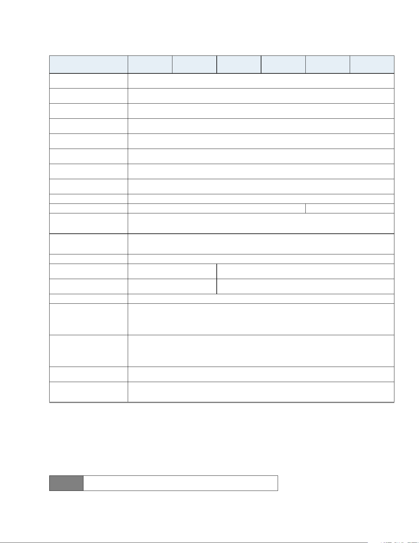
Table 1 Drive specifications summary
Drive Specification*
ST8000VX009,
ST8000VX010
ST6000VX008,
ST6000VX009
ST4000VX015,
ST4000VX016
ST3000VX014,
ST3000VX015
ST2000VX016,
ST2000VX017
ST1000VX012,
ST1000VX013
Formatted capacity
(512 bytes/sector)**
8000GB (8TB) 6000GB (6TB) 4000GB (4TB) 3000GB (3TB) 2000GB (2TB) 1000GB (1TB)
Guaranteed sectors 15,628,053,168 11,721,045,168 7,814,037,168 5,860,533,168 3,907,029,168 1,953,525,168;
Heads 8 4 2
Disks 4 2 1
Bytes per sector
(emulated at 512-byte sectors)
4096 (physical)
Default sectors per track 63
Default read/write heads 16
Default cylinders 16,383
Recording density 2448 kB/in
Track density (avg) 480 ktracks/in
Areal density (avg) 1175 Gb/in
2
SATA interface transfer rate 600 MB/s
Maximum data transfer rate 180 MB/s
ATA data-transfer modes
supported
PIO modes: 0 to 4
Multiword DMA modes: 0 to 2
Ultra DMA modes 0 to 6
Cache buffer 256MB
Height 26.1mm / 1.028 in (max) 20.20mm / 0.795 in (max)
Width 101.6mm (± 0.25) / 4.0 in (± 0.010)
Length 146.99mm / 5.787 in (max)
Weight (typical) 630g / 1.389 lb 490g / 1.08 lb 415g / 0.915 lb
Average latency 6.0 ms
Power-on to ready (typ) 15.0s 10.0 8.0
Standby to ready (typ) 15.0s 10.0 8.0
Startup current (typical) 12V 1.8A
Voltage tolerance
(including noise)
5V ±5%
12V ±10%
Non-Operating (Ambient °C) –40° to 70°
Seagate SkyHawk Product Manual, Rev. G 9
www.seagate.com Drive Specifications
* All specifications above are based on native configurations.
** One GB equals one billion bytes and 1TB equals one trillion bytes when referring to hard drive capacity.
Accessible capacity may vary depending on operating environment and formatting.
*** During periods of drive idle, some offline activity may occur according to the S.M.A.R.T.
specification, which may increase acoustic and power to operational levels.
† Seagate does not recommend operating at sustained case temperatures above 60°C.
Operating at higher temperatures will reduce useful life of the product.
# The operating temperature is 0 to 65°C (32 to 149°F).
Operating ambient
temperature (min °C)
#
0°
Operating temperature
(drive reported max °C)
65
†
Temperature gradient
20°C per hour max (operating)
30°C per hour max (non-operating)
Relative humidity
5% to 90% (operating)
5% to 95% (non-operating)
Relative humidity gradient
(max)
30% per hour
Wet bulb temperature (max)
30°C max (operating)
40°C max (non-operating)
Altitude, operating
–304m to 3048m
(–1000 ft to 10,000 ft)
Altitude, non-operating
(below mean sea level, max)
–304m to12,192m
(–1000 ft to 40,000+ ft)
Operational shock (max) 80 Gs (read) / 70 Gs (write) at 2ms
Non-operational shock (max) 300 Gs at 2ms 350 Gs at 2ms
Vibration, operating
10Hz to 22Hz: 0.25 Gs, Limited displacement
22Hz to 350Hz: 0.50 Gs
350Hz to 500Hz: 0.25 Gs
Vibration, non-operating
5Hz to 22Hz: 3.0 Gs
22Hz to 350Hz: 3.0 Gs
350Hz to 500Hz: 3.0 Gs
Drive acoustics, sound power
Idle***
2.6 bels (typical)
2.7 bels (max)
2.3 bels (typical)
2.4 bels (max)
Seek
2.8 bels (typical)
2.9 bels (max)
2.7 bels (typical)
2.8 bels (max)
Non-recoverable read errors 1 per 10
14
bits read
Rated workload
Average annualized workload rating: <180TB/year.
The specifications for the product assumes the I/O workload does not exceed the average annualized workload
rate limit of 180TB/year. Workloads exceeding the annualized rate may degrade and impact reliability as
experienced by the particular application. The average annualized workload rate limit is in units of TB per calendar
year.
Warranty
To determine the warranty for a specific drive, use a web browser to access the following web page:
www.seagate.com/support/warranty-and-replacements/
From this page, click on “Is my Drive under Warranty”. Users will be asked to provide the drive serial number,
model number (or part number) and country of purchase. The system will display the warranty information for the
drive.
Load/unload cycles
(at 25°C, 50% rel. humidity)
600,000
Supports hotplug operation
per the Serial ATA Revision 3.3
specification
Yes
Note
If the drive is powered-off before issuing flush cache command, in some instances,
the end user data in the DRAM cache might not be committed to the disk.
Table 1 Drive specifications summary (continued)
Drive Specification*
ST8000VX009,
ST8000VX010
ST6000VX008,
ST6000VX009
ST4000VX015,
ST4000VX016
ST3000VX014,
ST3000VX015
ST2000VX016,
ST2000VX017
ST1000VX012,
ST1000VX013
Seagate SkyHawk Product Manual, Rev. G 10
www.seagate.com Drive Specifications
2.2 Formatted capacity
*One GB equals one billion bytes and 1TB equals one trillion bytes when referring to hard drive capacity. Accessible capacity may vary
depending on operating environment and formatting.
2.2.1 LBA mode
When addressing these drives in LBA mode, all blocks (sectors) are consecutively numbered from 0 to n–1, where n is the
number of guaranteed sectors as defined above.
See Section 4.3.1, "Identify Device command" (words 60-61 and 100-103) for additional information about 48-bit
addressing support of drives with capacities over 137GB.
2.3 Default logical geometry
• Cylinders: 16,383
• Read/write heads: 16
• Sectors per track: 63
LBA mode
When addressing these drives in LBA mode, all blocks (sectors) are consecutively numbered from 0 to n–1, where n is the
number of guaranteed sectors as defined above.
2.4 Recording and interface technology
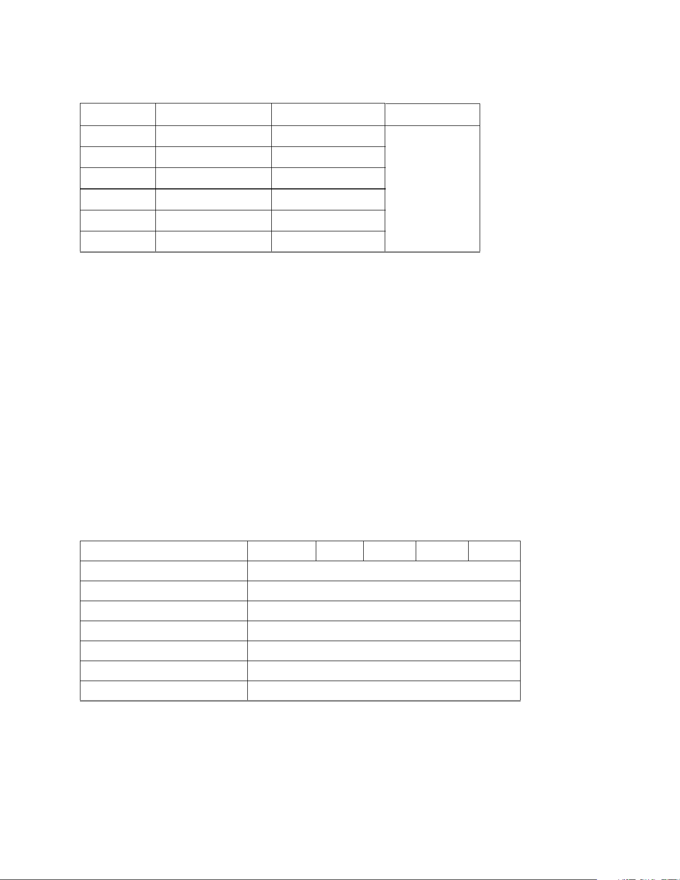
Model Formatted capacity* Guaranteed sectors Bytes per sector
8TB 8000GB 15,628,053,168
4096
6TB 6000GB 11,721,045,168
4TB 4000GB 7,814,037,168
3TB 3000GB 5,860,533,168
2TB 2000GB 3,907,029,168
1TB 1000GB 1,953,525,168;
Models 8TB & 6TB 4TB 3TB 2TB 1TB
Interface SATA
Recording method CMR
Recording density (kBPI) 2448
Track density (ktracks/inch avg) 480
Areal density (Gb/in
2
)1175
Interface transfer rate (MB/s) 600
Data transfer rate (MB/s) up to 180
Seagate SkyHawk Product Manual, Rev. G 11
www.seagate.com Drive Specifications
2.5 Physical characteristics
2.6 Start/stop times
The start/stop times are listed below.
Time-to-ready may be longer than normal if the drive power is removed without going through normal OS powerdown
procedures.
Height
8TB & 6TB 26.1mm / 1.028 in (max)
4TB, 3TB, 2TB & 1TB 20.20mm / 0.795 in (max)
Width 101.6mm (± 0.25) / 4.0 in (± 0.010 in)
Length 146.99mm / 5.787 in (max)
Typical weight
8TB & 6TB 630g / 1.389 lb
4TB & 3TB 490g / 1.08 lb
2TB & 1TB 415g / 0.915 lb
Cache buffer 256MB
8TB & 6TB models 4TB & 3TB models 2TB & 1TB models
Power-on to ready
(in seconds)
15 (typical) 10 (typical) 8 (typical)
Standby to ready
(in seconds)
15 (typical) 10 (typical) 8 (typical)
Ready to spindle stop
(in seconds)
18 (typical) 12 (typical) 10 (typical)
Seagate SkyHawk Product Manual, Rev. G 12
www.seagate.com Drive Specifications
2.7 Power specifications
The drive receives DC power (+5V or +12V) through a native SATA power connector. Refer to Figure 3 on page 22.
2.7.1 Power consumption
Power requirements for the drives are listed in Table 2. Typical power measurements are based on an average of drives
tested, under nominal conditions, using 5.0V and 12.0V input voltage at 25°C ambient temperature. These power
measurements are done with DIPM enabled.
• Spinup current is measured from the time of power-on to the time that the drive spindle reaches operating
speed.
• Operating Power is measured following IDEMA 3 streams standard, assuming CE operating condition
• The drive supports three idle modes: Performance Idle mode, Active Idle mode and Low Power Idle mode.
Refer to Section 2.7.4 for power-management mode.
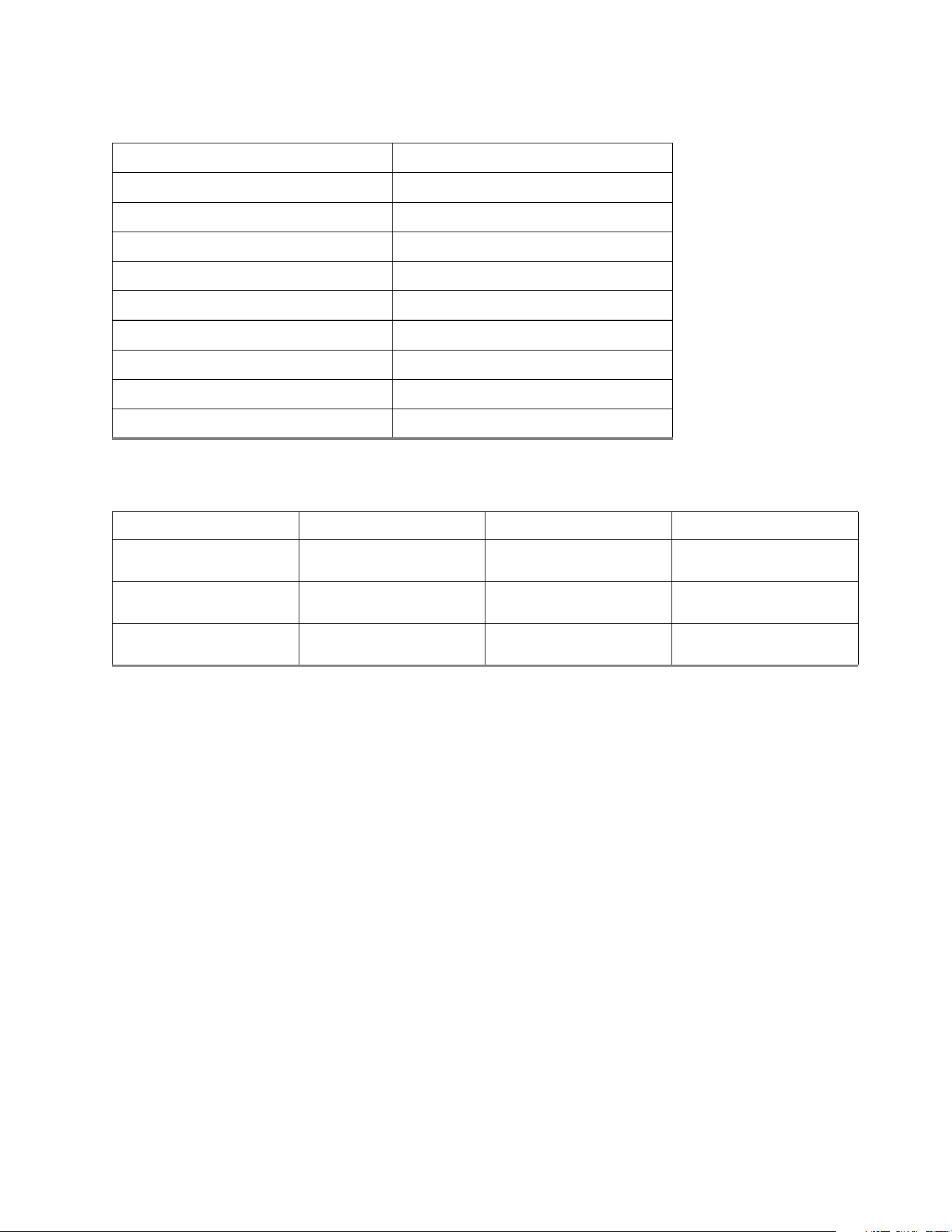
Table 2 DC power requirements (8TB & 6TB)
Power dissipation Avg (watts 25° C) Avg 5V typ amps Avg 12V typ amps
Spinup — — 1.8
Idle, Low Power 3.4 0.10 0.242
Operating Power 5.3 0.28 0.325
Standby 0.25 0.04 0.004
Sleep 0.25 0.04 0.004
Table 3 DC power requirements (4TB, 3TB, 2TB & 1TB)
Power dissipation Avg (watts 25° C) Avg 5V typ amps Avg 12V typ amps
Spinup — — 1.8
Idle, Low Power 2.5 0.12 0.15
Operating Power 3.7 0.28 0.191
Standby 0.25 0.04 0.004
Sleep 0.25 0.04 0.004
Seagate SkyHawk Product Manual, Rev. G 14
www.seagate.com Drive Specifications
2.7.2 Conducted noise
Input noise ripple is measured at the host system power supply across an equivalent 80-ohm resistive load on the +12 volt
line or an equivalent 15-ohm resistive load on the +5 volt line.
• Using 12-volt power, the drive is expected to operate with a maximum of 120 mV peak-to-peak sine-wave injected noise
at up to 10MHz.
• Using 5-volt power, the drive is expected to operate with a maximum of 100 mV peak-to-peak sine-wave injected noise
at up to 10MHz.
2.7.3 Voltage tolerance
Voltage tolerance (including noise):
•5VDC ±5%
• 12VDC ±10%
2.7.4 Power-management modes
The drive provides programmable power management to provide greater energy efficiency. In most systems, users can
control power management through the system setup program. The drive features the following power-management
modes:
•Active mode
The drive is in Active mode during the read/write and seek operations.
• Idle mode
The electronics remain powered, and the drive accepts all commands and returns to Active mode when disk access
is necessary.
•Standby mode
The drive enters Standby mode immediately when the host sends a Standby Immediate command. If the host has
set the standby timer, the drive enters Standby mode automatically after the drive has been inactive for a specifi-
able length of time. The standby timer delay is established using a Standby or Idle command. In Standby mode, the
electronics are in low power mode, the heads are parked and the spindle is at rest. The drive accepts all commands
and returns to Active mode when disk access is necessary.
• Sleep mode
The drive enters Sleep mode after receiving a Sleep command from the host. In Sleep mode, the electronics are in
low power mode, the heads are parked and the spindle is at rest. The drive leaves Sleep mode after it receives a Hard
Reset or Soft Reset from the host. After receiving a reset, the drive exits Sleep mode and enters Standby mode.
• Idle and Standby timers
Each time the drive performs an Active function (read, write or seek), the standby timer is reinitialized and begins
counting down from its specified delay times to zero. If the standby timer reaches zero before any drive activity is
required, the drive makes a transition to Standby mode. In both Idle and Standby mode, the drive accepts all com-
mands and returns to Active mode when disk access is necessary.
Note
Equivalent resistance is calculated by dividing the nominal voltage by the typical RMS read/write current.
Power modes Heads Spindle Electronics
Active Tracking Rotating Full Power
Idle, Performance Tracking Rotating Full Power
Idle, Active Floating Rotating Partial Power
Idle, Low Power Parked Rotating Partial Power
Standby Parked Stopped Low Power
Sleep Parked Stopped Low Power
Seagate SkyHawk Product Manual, Rev. G 15
www.seagate.com Drive Specifications
2.8 Environmental specifications
This section provides the temperature, humidity, shock, and vibration specifications for SkyHawk drives. Ambient
temperature is defined as the temperature of the environment immediately surrounding the drive. Above 1000ft. (305
meters), the maximum temperature is derated linearly by 1°C every 1000 ft. Refer to
Section 3.4 on page 23 for base plate
measurement location.
2.8.1 Ambient Temperature
† Seagate does not recommend operating at sustained case temperatures above 60°C.
Operating at higher temperatures will reduce useful life of the product.
2.8.2 Temperature gradient
2.8.3 Humidity
2.8.3.1 Relative humidity
2.8.3.2 Wet bulb temperature
2.8.4 Altitude
Non-operating (Ambient) –40° to 70°C (–40° to 158°F)
Operating ambient (min °C) 0° (32°F)
Operating (Drive reported max °C) 65° (149°F)
†
Operating 20°C per hour (36°F per hour max), without condensation
Non-operating 30°C per hour (54°F per hour max)
Operating 5% to 90% non-condensing (30% per hour max)
non-operating 5% to 95% non-condensing (30% per hour max)
Operating 30°C / 86°F (rated)
Non-operating 40°C / 104°F (rated)
Operating –304m to 3048m (–1000 ft. to 10,000 ft.)
Non-operating –304m to 12,192m (–1000 ft. to 40,000+ ft.)
Seagate SkyHawk Product Manual, Rev. G 16
www.seagate.com Drive Specifications
2.8.5 Shock
All shock specifications assume that the drive is mounted securely with the input shock applied at the drive mounting
screws. Shock may be applied in the X, Y or Z axis.
2.8.5.1 Operating shock
These drives comply with the performance levels specified in this document when subjected to a maximum operating
shock of 80 Gs (read) / 70 Gs (write) based on half-sine shock pulses of 2ms during read operations. Shocks should not be
repeated more than two times per second.
2.8.5.2 Non-operating shock
8TB, 6TB, 4TB and 3TB models
The non-operating shock level that the drive can experience without incurring physical damage or degradation in
performance when subsequently put into operation is 300 Gs based on a non-repetitive half-sine shock pulse of
2ms duration.
2TB and 1TB models
The non-operating shock level that the drive can experience without incurring physical damage or degradation in
performance when subsequently put into operation is 350 Gs based on a non-repetitive half-sine shock pulse of
2ms duration.
2.8.6 Vibration
All vibration specifications assume that the drive is mounted securely with the input vibration applied at the drive
mounting screws. Vibration may be applied in the X, Y or Z axis. Throughput may vary if improperly mounted.
2.8.6.1 Operating vibration
The maximum vibration levels that the drive may experience while meeting the performance standards specified in this
document are specified below.
2.8.6.2 Non-operating vibration
The maximum non-operating vibration levels that the drive may experience without incurring physical damage or
degradation in performance when subsequently put into operation are specified below.
10Hz to 22Hz 0.25 Gs (Limited displacement)
22Hz to 350Hz 0.50 Gs
350Hz to 500Hz 0.25 Gs
5Hz to 22Hz 3.0 Gs (Limited displacement)
22Hz to 350Hz 3.0 Gs
350Hz to 500Hz 3.0 Gs
Seagate SkyHawk Product Manual, Rev. G 17
www.seagate.com Drive Specifications
2.9 Acoustics
Drive acoustics are measured as overall A-weighted acoustic sound power levels (no pure tones). All measurements are
consistent with ISO document 7779. Sound power measurements are taken under essentially free-field conditions over a
reflecting plane. For all tests, the drive is oriented with the cover facing upward.
*During periods of drive idle, some offline activity may occur according to the S.M.A.R.T. specification, which may increase acoustic and
power to operational levels.
2.9.1 Test for Prominent Discrete Tones (PDTs)
Seagate follows the ECMA-74 standards for measurement and identification of PDTs. An exception to this process is the
use of the absolute threshold of hearing. Seagate uses this threshold curve (originated in ISO 389-7) to discern tone
audibility and to compensate for the inaudible components of sound prior to computation of tone ratios according to
Annex D of the ECMA-74 standards.
2.10 Electromagnetic immunity
When properly installed in a representative host system, the drive operates without errors or degradation in performance
when subjected to the radio frequency (RF) environments defined in
Table 5.
Note
For seek mode tests, the drive is placed in seek mode only.
The number of seeks per second is defined by the following equation:
(Number of seeks per second = 0.4 / (average latency + average access time
Table 4 Fluid Dynamic Bearing (FDB) motor acoustics
Idle* Seek
8TB & 6TB models
2.6 bels (typical)
2.7 bels (max)
2.8 bels (typical)
2.9 bels (max)
4TB, 3TB, 2TB & 1TB models
2.3 bels (typical)
2.4 bels (max)
2.7 bels (typical)
2.8 bels (max)
Table 5 Radio frequency environments
Tes t Des cripti on
Performance
level
Reference
standard
Electrostatic discharge Contact, HCP, VCP: ± 4 kV; Air: ± 8 kV B EN61000-4-2: 95
Radiated RF immunity 80MHz to 1,000MHz, 3 V/m,
80% AM with 1kHz sine
A EN61000-4-3: 96
Electrical fast transient ± 1 kV on AC mains, ± 0.5 kV on external I/O B EN61000-4-4: 95
Surge immunity ± 1 kV differential, ± 2 kV common,
AC mains
B EN61000-4-5: 95
Conducted RF immunity 150kHz to 80MHz, 3 Vrms, 80% AM with 1kHz sine A EN61000-4-6: 97
Voltage dips, interrupts 0% open, 5 seconds
0% short, 5 seconds
40%, 0.10 seconds
70%, 0.01 seconds
C
C
C
B
EN61000-4-11: 94

Seagate SkyHawk Product Manual, Rev. G 18
www.seagate.com Drive Specifications
2.11 Reference documents
Supported standards
Serial ATA Revision 3.3 specification
ANSI Documents
SFF-8301 3.5” Drive Form Factor with Serial Connector
INCITS 522-2014 SCSI Protocol Layer-4 (SPL-4) Rev. 08
Specification for Acoustic Test Requirement and Procedures
Seagate part number: 30553-001
In case of conflict between this document and any referenced document, this document takes precedence.
2.12 Warranty
To determine the warranty for a specific drive, use a web browser to access the following web page:
www.sea
gate.com/support/warranty-and-replacements/
From this page, click on “Is my Drive under Warranty”. Users will be asked to provide the drive serial number, model
number (or part number) and country of purchase. The system will display the warranty information for the drive.
2.12.1 Data loss under power interruption with write cache enabled
Drive preserves its data during all operations except in cases where power to the drive is interrupted during write
operations. This could result in either an uncorrected data error being reported, or the entire sector/track becoming
unreadable. This can be permanently recovered by rewriting to the same location on the drive. Additionally any data
present in the DRAM buffer will not be written to the disk media, additionally, the drive will not be able to return the
original data.
In order to prevent this data loss, the host should issue a standby immediate or flush cache command before a controlled
power off operation to the drive.
2.12.2 Storage
Maximum storage periods are 180 days within original unopened Seagate shipping package or 60 days unpackaged
within the defined non-operating limits (refer to environmental section in this manual). Storage can be extended to 1 year
packaged or unpackaged under optimal environmental conditions (25°C, <40% relative humidity non-condensing, and
non-corrosive environment). During any storage period the drive non-operational temperature, humidity, wet bulb,
atmospheric conditions, shock, vibration, magnetic and electrical field specifications should be followed.
Seagate SkyHawk Product Manual, Rev. G 19
www.seagate.com Drive Specifications
2.13 Reliability
2.13.1 Annualized Failure Rate (AFR) and Mean Time Between Failures (MTBF)
The production disk drive shall achieve an annualized failure-rate of 0.87% (MTBF of 1,000,000 hours) over a 3 year service
life when used in Surveillance Storage field conditions as limited by the following:
• 8760 power-on hours per year.
• Ambient wet bulb temp <= 25°C
• Typical surveillance workload
• The AFR (MTBF) is a population statistic not relevant to individual units
• ANSI/ISA S71.04-2013 G2 classification levels and dust contamination to ISO 14644-1 Class 8 standards (as measured at
the device)
The MTBF specification for the drive assumes the operating environment is designed to maintain nominal drive
temperature and humidity. Occasional excursions in operating conditions between the rated MTBF conditions and the
maximum drive operating conditions may occur without significant impact to the rated MTBF. However continual or
sustained operation beyond the rated MTBF conditions will degrade the drive MTBF and reduce product reliability.
2.13.2 HDD and SSD Regulatory Compliance and Safety
For the latest regulatory and compliance information see: www.seagate.com/support/ scroll down the page
and click the Compliance, Safety and Disposal Guide link.
2.13.3 Safety certification
The following regulatory model number represent all features and configurations within the series:
SKR007: 3/4D (8TB & 6TB Models)
SKR006: 1/2D (4TB, 3TB, 2TB & 1TB Models)
2.14 Corrosive environment
Seagate electronic drive components pass accelerated corrosion testing equivalent to 10 years exposure to light industrial
environments containing sulfurous gases, chlorine and nitric oxide, classes G and H per ASTM B845. However, this
accelerated testing cannot duplicate every potential application environment. Users should use caution exposing any
electronic components to uncontrolled chemical pollutants and corrosive chemicals as electronic drive component
reliability can be affected by the installation environment. The silver, copper, nickel and gold films used in Seagate
products are especially sensitive to the presence of sulfide, chloride, and nitrate contaminants. Sulfur is found to be the
most damaging. In addition, electronic components should never be exposed to condensing water on the surface of the
printed circuit board assembly (PCBA) or exposed to an ambient relative humidity greater than 95%. Materials used in
cabinet fabrication, such as vulcanized rubber, that can outgas corrosive compounds should be minimized or eliminated.
The useful life of any electronic equipment may be extended by replacing materials near circuitry with sulfide-free
alternatives.
Nonrecoverable read errors 1 per 10
14
bits read, max
Load unload cycles
(command controlled)
600,000 cycles
Maximum Rated Workload
Maximum rate of <180TB/year
Workloads exceeding the annualized rate may degrade the drive MTBF and impact product
reliability. The Annualized Workload Rate is in units of TB per year, or TB per 8760 power on
hours. Workload Rate = TB transferred * (8760 / recorded power on hours).
Warranty
To determine the warranty for a specific drive, use a web browser to access the following web
page: www.sea
gate.com/support/warranty-and-replacements/.
From this page, click on the “Is my Drive under Warranty” link. The following are required to be
provided: the drive serial number, model number (or part number) and country of purchase.
The system will display the warranty information for the drive.
Preventive maintenance None required.

Seagate SkyHawk Product Manual, Rev. G 20
2.15 Seagate® Rescue
™
Data Recovery Service
If you suffer a data loss event within the Seagate Rescue Data Recovery warranty period, and you are eligible to participate in
and submit a case under the Rescue program, contact SRS at (1-800-723-1183) in the US, or if you are calling from outside the
US please visit our website for numbers in your local and language: www.seagate.com/contacts/contact-numbers/.
In addition, you may visit rescueandreplace.seagate.com/contact.jsp to obtain information regarding how to contact a
recovery expert online or by telephone from your location. An SRS representative will review your case to confirm your
eligibility, and to assess whether your data may be recoverable by remote recovery services or whether you will need to send
your device to SRS for in-lab servicing.
Rescue™ General Terms
These Rescue™ General Terms together with the Rescue™ FAQ’s make up the Rescue™ Program Terms. By submitting a case
under the Rescue
™ program (“Program”) you agree to be bound by the Program Terms, including these General Terms and
the FAQ. You must be a legal resident of the US to participate in the Program.
Communications. All communications relating to your request will be available on our web site in your account and sent via
e-mail to the address you provide to us unless you request, in writing, to receive such communications via regular mail.
Personal Data. You must provide true, accurate and complete information about yourself as prompted by the request form,
including, without limitation, your name, address, e-mail address, and telephone number, as applicable (collectively,
“Personal Data”). You must maintain and promptly update your Personal Data. You acknowledge that we may send you
important information and notices regarding your requests by e-mail and that we shall have no liability associated with or
arising from your failure to maintain accurate Personal Data.
Capacity; Legal Rights; Indemnity. You represent to SRS that you are of the legal age of majority in your state or country of
residence, with the full capacity to agree to these Program Terms. You warrant that you are the legal owner or the authorized
representative of the legal owner of the device you submit to SRS (the “Device”) and data. You warrant that the data on the
Device is legal and that you have the unrestricted legal right to (a) give us remote access to the data, (b) have the data
recovered and reproduced on a backup medium, (c) receive the recovered data, and (d) agree to these Program Terms. You
will defend and indemnify us (including our directors, officers, employees, agents, delegates, and contractors) from any claims
or actions relating to the Device or data, or your rights or lack of rights thereto.
Confidentiality. We will protect the confidentiality of your data against unauthorized disclosure using the same degree of
care as we use to protect our own confidential information.
Disclaimer of Warranties, Representations and Guarantees. WE PROVIDE THE PROGRAM AND ANY SERVICES
PROVIDED OR ATTEMPTED HEREUNDER “AS IS,” WITH ALL FAULTS, AT YOUR SOLE RISK. WE DO NOT EXTEND ANY
EXPRESS WARRANTIES, REPRESENTATIONS, CONDITIONS OR GUARANTEES REGARDING OUR RESCUE SERVICES OR
ANY RESULTS THEREOF. TO THE MAXIMUM EXTENT PERMITTED BY APPLICABLE LAW AND SUBJECT TO ANY
STATUTORY WARRANTIES THAT CANNOT BE EXCLUDED, WE EXPRESSLY DISCLAIM ALL IMPLIED WARRANTIES,
INCLUDING ANY IMPLIED WARRANTY OR CONDITION OF MERCHANTABILITY, WARRANTY OF FITNESS FOR A
PARTICULAR PURPOSE, OR WARRANTY OF ACCURACY OR COMPLETENESS WITH RESPECT TO THIS PROGRAM AND
SERVICES. This Program and Disclaimer is unrelated to, and does not affect any warranties relating to your Device that we or
the seller may have extended to you.
Limitation of Liability. WE WILL NOT BE LIABLE FOR ANY HARM CAUSED, UNLESS YOU PROVE THAT WE CAUSED SUCH
HARM INTENTIONALLY. WITHOUT LIMITING THE GENERALITY OF THE FOREGOING, WE WILL NOT BE LIABLE FOR THE
CONDITION, EXISTENCE, OR LOSS OF THE DATA YOU SEND US OR THE DATA WE RECOVER (IF ANY), ANY LOSS OF
REVENUE OR LOSS OF PROFITS, OR ANY INDIRECT, SPECIAL, INCIDENTAL, OR CONSEQUENTIAL DAMAGES HOWEVER
CAUSED. TO THE MAXIMUM EXTENT PERMITTED BY APPLICABLE LAW, THIS LIMITATION SHALL APPLY TO ANY AND
ALL DAMAGES, REGARDLESS OF THE LEGAL THEORY ON WHICH THEY ARE ASSERTED (INCLUDING, WITHOUT
LIMITATION, CONTRACT, BREACH OF CONTRACT, AND TORT), AND REGARDLESS OF WHETHER WE HAVE BEEN
ADVISED OF THE POSSIBILITY OF LOSS OR DAMAGES - UNLESS YOU PROVE THAT SRS CAUSED DAMAGES TO YOU
INTENTIONALLY. TO THE MAXIMUM EXTENT PERMITTED BY APPLICABLE LAW, THE AMOUNT OF OUR LIABILITY WILL
NOT EXCEED THE TOTAL PRICE YOU ACTUALLY PAY FOR THE DEVICE, THE ESSENTIAL PURPOSE OF WHICH IS TO LIMIT
OUR LIABILITY ARISING FROM OR RELATED TO THE PROGRAM AND ANY DATA RECOVERY SERVICES. THIS
ALLOCATION OF RISK IS REFLECTED IN THE PRICE CHARGED FOR THIS PROGRAM OR SERVICES, IF ANY. YOU
ACKNOWLEDGE THAT THE PRICE OF THIS PROGRAM WOULD BE MUCH GREATER IF WE UNDERTOOK MORE EXTENSIVE
LIABILITY. THIS PARAGRAPH WILL APPLY NOTWITHSTANDING ANY OTHER PROVISIONS IN THESE TERMS, OR THE
FAILURE OF ANY REMEDY.

Seagate SkyHawk Product Manual, Rev. G 21
www.seagate.com Drive Specifications
Compliance with Laws. You agree to comply with all such laws and regulations and all other applicable laws, statutes,
ordinances and regulations relating to the Program. You acknowledge that violations of these Program Terms could subject
you to criminal or civil penalties. The goods licensed or provided, or services provided, through the Program, which may
include technology and software, are subject to the customs and export control laws and regulations of the U.S. and may also
be subject to the customs and export laws and regulations of the country in which the products are manufactured or
received. Further, under U.S. law, such goods may not be sold, leased or otherwise transferred to restricted countries, or used
by a restricted end-user or an end-user engaged in activities related to weapons of mass destruction including, without
limitation, activities related to designing, developing, producing or using nuclear weapons, materials, or facilities, missiles or
supporting missile projects, or chemical or biological weapons. You acknowledge you are not a restricted end-user or
involved in any of the restricted activities above, and that you will comply with and abide by these laws and regulations.
Seagate reserves the right to refuse service to or the return of any storage devices that have been determined to violate these
regulations.
Cancellation. You may cancel the Program at any time by contacting SRS at 1-800-SEAGATE (1-800-475-0143) in the US, or at
such other number available at services.sea
gate.com/contact.aspx, or you simply may refrain from submitting a request for
Rescue services. These Program Terms remain applicable to your and SRS’s rights and obligations with respect to any services
requested by you under this Program.
Assignment. You may not assign your rights or obligations under these Program Terms without SRS’ express written consent.
Dispute Resolution. The parties will attempt to resolve any dispute arising out of or related to these Program Terms or any
data recovery services requested or attempted hereunder through good faith negotiation. To the extent permitted by
applicable law, if the parties are unable to resolve the dispute through good faith negotiation, then the dispute will be
submitted to final and binding arbitration with the Judicial Arbitration and Mediation Services. Each party will bear its own
costs in arbitration, provided that Seagate reserves the right, in its discretion, to pre-pay certain fees you may incur in
connection with the arbitration subject to refund if you do not prevail. Both parties waive their rights to a jury trial. All
proceedings will take place in Santa Clara County, California, USA. The laws of the State of California will exclusively govern
these Program Terms and our provision of any data recovery services, without regard to California's conflicts of laws rules. You
consent to the exclusive jurisdiction of the courts located in Santa Clara County, California, USA.
Severability. If any provision of these Program Terms is held invalid, illegal or unenforceable, such provision shall be enforced
to the fullest extent permitted by applicable law and the validity, legality and enforceability of the remaining provisions shall
not be affected thereby.
Legal Effect. These Program Terms describe certain legal rights. You may have other rights under applicable law. These
Program Terms do not change your rights under applicable law if such laws do not permit these Program Terms to do so. Also,
the Program and these Program Terms are in addition and unrelated to any rights you may have under a Seagate warranty
statement.
SRS Companies. The following SRS companies may provide the services described in these Program Terms: (a) Seagate
Technology LLC, with offices at 3101 Jay Street, Suite 110, Santa Clara, California 95054; (b) Seagate Technology Canada Inc.,
with offices at 2421 Bristol Circle, Suite A100, Oakville, Ontario, Canada L6H 5S9; and/or (c) Seagate Technology (Netherlands)
B.V., with offices at Koolhovenlaan 1, 1119 PA, Schiphol-Rijk, The Netherlands.
Seagate SkyHawk Product Manual, Rev. G 22
3.0 Configuring and Mounting the Drive
This section contains the specifications and instructions for configuring and mounting the drive.
3.1 Handling and static-discharge precautions
After unpacking, and before installation, the drive may be exposed to potential handling and electrostatic discharge (ESD)
hazards. Observe the following standard handling and static-discharge precautions:
Caution
• Before handling the drive, put on a grounded wrist strap, or ground oneself frequently by touching the metal chassis of
a computer that is plugged into a grounded outlet. Wear a grounded wrist strap throughout the entire installation
procedure.
• Handle the drive by its edges or frame only.
• The drive is extremely fragile—handle it with care. Do not press down on the drive top cover.
• Always rest the drive on a padded, antistatic surface until users mount it in the computer.
• Do not touch the connector pins or the printed circuit board.
• Do not remove the factory-installed labels from the drive or cover them with additional labels. Removal voids the warranty.
Some factory-installed labels contain information needed to service the drive. Other labels are used to seal out dirt and
contamination.
3.2 Configuring the drive
Each drive on the SATA interface connects point-to-point with the SATA host adapter. There is no master/slave relationship
because each drive is considered a master in a point-to-point relationship. If two drives are attached on one SATA host
adapter, the host operating system views the two devices as if they were both “masters” on two separate ports. Both drives
behave as if they are Device 0 (master) devices.
SATA drives are designed for easy installation. It is usually not necessary to set any jumpers on the drive for proper
operation; however, if users connect the drive and receive a “drive not detected” error, the SATA-equipped motherboard or
host adapter may use a chipset that does not support SATA speed autonegotiation.
3.3 SATA cables and connectors
The SATA interface cable consists of four conductors in two differential pairs, plus three ground connections. The cable size
may be 30 to 26 AWG with a maximum length of one meter (39.37 inches). See
Table 6 for connector pin definitions. Either
end of the SATA signal cable can be attached to the drive or host.
For direct backplane connection, the drive connectors are inserted directly into the host receptacle. The drive and the host
receptacle incorporate features that enable the direct connection to be hot pluggable and blind mateable.
For installations which require cables, users can connect the drive as illustrated in
Figure 3.
Figure 3 Attaching SATA cabling
Each cable is keyed to ensure correct orientation. SkyHawk drives support latching SATA connectors.
Seagate SkyHawk Product Manual, Rev. G 23
www.seagate.com Configuring and Mounting the Drive
3.4 Drive mounting
Users can mount the drive in any orientation using four screws in the side-mounting holes or four screws in the bottom-
mounting holes. Refer to
Figure 4 for drive mounting dimensions. Follow these important mounting precautions when
mounting the drive:
• Allow a minimum clearance of 0.030 inches (0.76mm) around the entire perimeter of the drive for cooling.
• Use only 6-32 UNC mounting screws.
• The screws should be inserted no more than 0.140 inch (3.56mm) into the bottom or side mounting holes.
• Do not overtighten the mounting screws (maximum torque: 8 inch-lb).
Figure 4 Mounting dimensions (4TB, 3TB, 2TB & 1TB models)
Seagate SkyHawk Product Manual, Rev. G 25
www.seagate.com SATA Interface
4.0 SATA Interface
These drives use the industry-standard Serial ATA (SATA) interface that supports FIS data transfers. It supports ATA
programmed input/output (PIO) modes 0 to 4; multiword DMA modes 0 to 2, and Ultra DMA modes 0 to 6.
For detailed information about the SATA interface, refer to the “Serial ATA: High Speed Serialized AT Attachment”
specification.
4.1 Hot-Plug compatibility
SkyHawk drives incorporate connectors which enable users to hot plug these drives in accordance with the SATA Revision
3.3 specification. This specification can be downloaded from www.serialata.or
g.
4.2 SATA device plug connector pin definitions
Table 6 summarizes the signals on the SATA interface and power connectors.
Notes
1. All pins are in a single row, with a 1.27 mm (0.050 in) pitch.
2. The comments on the mating sequence apply to the case of backplane blindmate connector only. In this case, the mating
sequences are:
• the ground pins P4 and P12.
• the pre-charge power pins and the other ground pins.
• the signal pins and the rest of the power pins.
3. There are three power pins for each voltage. One pin from each voltage is used for pre-charge when installed in a blind-mate back-
plane configuration.
• All used voltage pins (V
x
) must be terminated.
Table 6 SATA connector pin definitions
Segment Pin Function Definition
Signal S1 Ground 2nd mate
S2 A+
Differential signal pair A from Phy
S3 A-
S4 Ground 2nd mate
S5 B-
Differential signal pair B from Phy
S6 B+
S7 Ground 2nd mate
Key and spacing separate signal and power segments
Power
P1
V
33
3.3V power
P2
V
33
3.3V power
P3
V33
3.3V power, pre-charge, 2nd mate
P4 Ground 1st mate
P5 Ground 2nd mate
P6 Ground 2nd mate
P7
V
5
5V power, pre-charge, 2nd mate
P8
V
5
5V power
P9
V5
5V power
P10 Ground 2nd mate
P11 Ground or LED signal If grounded, drive does not use deferred spin
P12 Ground 1st mate.
P13
V
12
12V power, pre-charge, 2nd mate
P14
V
12
12V power
P15
V
12
12V power

Seagate SkyHawk Product Manual, Rev. G 26
www.seagate.com SATA Interface
4.3 Supported ATA commands
The following table lists SATA standard commands that the drive supports.
For a detailed description of the ATA commands, refer to the Serial ATA International Organization:
Serial ATA Revision 3.0 (www.sata-io.or
g).
See “S.M.A.R.T. commands” on page 34 for details and subcommands used in the S.M.A.R.T. implementation.
Table 7 SATA standard commands
Command name Command code (in hex)
Check Power Mode E5
H
Device Configuration Freeze Lock B1
H
/ C1
H
Device Configuration Identify B1
H
/ C2
H
Device Configuration Restore B1
H
/ C0
H
Device Configuration Set B1
H
/ C3
H
Download Microcode 92
H
Execute Device Diagnostics 90
H
Flush Cache E7
H
Flush Cache Extended EA
H
Identify Device EC
H
Idle E3
H
Idle Immediate E1
H
Initialize Device Parameters 91
H
Read Buffer E4
H
Read DMA C8
H
Read DMA Extended 25
H
Read Log Ext 2F
H
Read Multiple C4
H
Read Multiple Extended 29
H
Read Native Max Address F8
H
Read Native Max Address Extended 27
H
Read Sectors 20
H
Read Sectors Extended 24
H
Read Verify Sectors 40
H
Read Verify Sectors Extended 42
H
Recalibrate 10
H
Security Disable Password F6
H
Security Erase Prepare F3
H
Security Erase Unit F4
H
Security Freeze F5
H
Security Set Password F1
H
Security Unlock F2
H
Seek 70
H
Set Features EF
H
Set Max Address F9
H
Seagate SkyHawk Product Manual, Rev. G 27
www.seagate.com SATA Interface
Note: Individual Set Max Address
commands are identified by the value
placed in the Set Max Features register as
defined to the right.
Address:
Password:
Lock:
Unlock:
Freeze Lock:
00H
01H
02H
03H
04H
Set Max Address Extended 37
H
Set Multiple Mode C6
H
Sleep E6
H
S.M.A.R.T. Disable Operations B0
H
/ D9
H
S.M.A.R.T. Enable/Disable Autosave B0
H
/ D2
H
S.M.A.R.T. Enable Operations B0
H
/ D8
H
S.M.A.R.T. Execute Offline B0
H
/ D4
H
S.M.A.R.T. Read Attribute Thresholds B0
H
/ D1
H
S.M.A.R.T. Read Data B0
H
/ D0
H
S.M.A.R.T. Read Log Sector B0
H
/ D5
H
S.M.A.R.T. Return Status B0
H
/ DA
H
S.M.A.R.T. Save Attribute Values B0
H
/ D3
H
S.M.A.R.T. Write Log Sector B0
H
/ D6
H
Standby E2
H
Standby Immediate E0
H
Write Buffer E8
H
Write DMA CA
H
Write DMA Extended 35
H
Write Log Extended 3F
H
Write Multiple C5
H
Write Multiple Extended 39
H
Write Sectors 30
H
Write Sectors Extended 34
H
Write Uncorrectable 45
H
Table 7 SATA standard commands (continued)
Command name Command code (in hex)
Seagate SkyHawk Product Manual, Rev. G 28
www.seagate.com SATA Interface
4.3.1 Identify Device command
The Identify Device command (command code EC
H
) transfers information about the drive to the host following power up.
The data is organized as a single 512-byte block of data, whose contents are shown in Table 7 on page 26. All reserved
bits or words should be set to zero. Parameters listed with an “x” are drive-specific or vary with the state of the drive.
The following commands contain drive-specific features that may not be included in the SATA specification.
Table 8 Identify Device commands
Word Description Value
0
Configuration information:
• Bit 15: 0 = ATA; 1 = ATAPI
• Bit 7: removable media
• Bit 6: removable controller
• Bit 0: reserved
0C5A
H
1 Number of logical cylinders 16,383
2
Specific configuration:
37C8h Device requires SET FEATURES subcommand to spin-up after power-up
and IDENTIFY DEVICE data is incomplete.
738Ch Device requires SET FEATURES subcommand to spin-up after power-up
and IDENTIFY DEVICE data is complete.
8C73h Device does not require SET FEATURES subcommand to spin-up after
power-up and IDENTIFY DEVICE data is incomplete.
C837h Device does not require SET FEATURES subcommand to spin-up after
power-up and IDENTIFY DEVICE data is complete.
C837
H
3 Number of logical heads 16
4 Retired 0000
H
5 Retired 0000
H
6 Number of logical sectors per logical track: 63 003F
H
7–9 Retired 0000
H
10–19 Serial number: (20 ASCII characters, 0000
H
= none) ASCII
20 Retired 0000
H
21 Retired 0000
H
22 Obsolete 0000
H
23–26 Firmware revision (8 ASCII character string, padded with blanks to end of string) x.xx
27–46 Drive model number: (40 ASCII characters, padded with blanks to end of string)
47 (Bits 7–0) Maximum sectors per interrupt on Read multiple and Write multiple (16) 8010
H
48
Trusted Computing feature set options:
15 Shall be cleared to zero
14 Shall be set to one
13:1 Reserved for the Trusted Computing Group
0 Trusted Computing feature set is supported
4000
H
49 Standard Standby timer, IORDY supported and may be disabled 2F00
H
50
Capabilities: (see 7.17.7.17)
15 Shall be cleared to zero
14 Shall be set to one
13:2 Reserved
1 Obsolete
0 Shall be set to one to indicate a vendor specific Standby timer value minimum
4000
H
Seagate SkyHawk Product Manual, Rev. G 29
www.seagate.com SATA Interface
51 PIO data-transfer cycle timing mode 0200
H
52 Retired (Obsolete) 0200
H
53
15:8 Free-fall Control Sensitivity
7:3 Reserved
2 the fields reported in word 88 are valid
1 the fields reported in words (70:64) are valid
0 Obsolete
0007
H
54 Number of current logical cylinders (Obsolete) xxxx
H
55 Number of current logical heads (Obsolete) xxxx
H
56 Number of current logical sectors per logical track (Obsolete) xxxx
H
57–58 Current capacity in sectors (Obsolete) xxxx
H
59
15 The BLOCK ERASE EXT command is supported
14 The OVERWRITE EXT command is supported
13 The CRYPTO SCRAMBLE EXT command is supported
12 The Sanitize feature set is supported
11:9 Reserved
8 Multiple logical sector setting is valid
7:0 Current setting for number of logical sectors that shall be transferred per DRQ
data block on READ/WRITE Multiple commands
0110
H
60–61
Total number of user-addressable LBA sectors available
(see Section 2.2 for related information)
*Note: The maximum value allowed in this field is: 0FFFFFFFh (268,435,455
sectors, 137GB). Drives with capacities over 137GB will have 0FFFFFFFh in this field
and the actual number of user-addressable LBAs specified in words 100-103. This
is required for drives that support the 48-bit addressing feature.
0FFFFFFFh*
62 Obsolete 0000
H
63
Multiword DMA active and modes supported
(see note following this table)
xx07
H
64 Advanced PIO modes supported (modes 3 and 4 supported) 0003
H
65 Minimum multiword DMA transfer cycle time per word (120 nsec) 0078
H
66 Recommended multiword DMA transfer cycle time per word (120 nsec) 0078
H
67 Minimum PIO cycle time without IORDY flow control (240 nsec) 0078
H
68 Minimum PIO cycle time with IORDY flow control (120 nsec) 0078
H
69
Additional Supported
15 CFast Specification Support
14 Deterministic data in trimmed LBA range(s) is supported
13 Long Physical Sector Alignment Error Reporting Control is supported
12 Obsolete
11 READ BUFFER DMA is supported
10 WRITE BUFFER DMA is supported
9 Obsolete
8 DOWNLOAD MICROCODE DMA is supported
7 Reserved for IEEE 1667
6 0 = Optional ATA device 28-bit commands supported
5 Trimmed LBA range(s) returning zeroed data is supported
4 Device Encrypts All User Data
3 Extended Number of User Addressable Sectors is supported
2 All write cache is non-volatile
1:0 Reserved
0000
H
Table 8 Identify Device commands (continued)
Word Description Value

Seagate SkyHawk Product Manual, Rev. G 30
www.seagate.com SATA Interface
70–74 ATA-reserved 0000
H
75 Queue depth 001F
H
76 SATA capabilities xxxx
H
77 Reserved for future SATA definition xxxx
H
78 SATA features supported xxxx
H
79 SATA features enabled xxxx
H
80 Major version number 07E0
H
81 Minor version number 006D
H
82 Command sets supported 364B
H
83 Command sets supported 7D61
H
84 Command sets support extension (see note following this table) 4133
H
85 Command sets enabled 34xx
H
86 Command sets enabled BC41
H
87 Command sets enable extension 4133
H
88 Ultra DMA support and current mode (see note following this table) xx7F
H
89 Security erase time xxxx
H
90 Enhanced security erase time xxxx
H
92 Master password revision code FFFE
H
93 Hardware reset value xxxx
H
94 Automatic acoustic management 8080
H
95–99 ATA-reserved xxxx
H
100–103
Total number of user-addressable LBA sectors available (see Section 2.2 for
related information). These words are required for drives that support the 48-bit
addressing feature. Maximum value: 0000FFFFFFFFFFFFh.
8TB models = 15,628,053,168
6TB models = 11,721,045,168
4TB models = 7,814,037,168
3TB models = 5,860,533,168
2TB models = 3,907,029,168
1TB models = 1,953,525,168;
104-105 ATA-reserved 0000
H
106 Physical sector size / logical sector size 6003
H
107 ATA-reserved 0000
H
108-111
The mandatory value of the world wide name (WWN) for the drive.
NOTE: This field is valid if word 84, bit 8 is set to 1 indicating 64-bit WWN support.
Each drive will have a unique
value.
112-118 ATA-reserved 0000
H
119 Commands and feature sets supported 40DC
H
120 Commands and feature sets supported or enabled 40DC
H
121-127 ATA-reserved 0000
H
128 Security status 0021
H
129–159 Seagate-reserved xxxx
H
160–167 ATA-reserved 0000
H
Table 8 Identify Device commands (continued)
Word Description Value
Seagate SkyHawk Product Manual, Rev. G 31
www.seagate.com SATA Interface
168 Device Nominal Form Factor 0002
H
169-205 ATA-reserved 0000
H
206 SCT Command Transport 70BD
H
207-208 ATA-reserved 0000
H
209 Alignment of logical blocks within a physical block 4000
H
210-216 ATA-reserved 0000
H
217 Nominal media rotation rate 1518
H
218-221 ATA-reserved 0000
H
222 Transport major version number 107F
H
223-229 ATA-reserved 0000
H
230-233 Extended Number of User Addressable Sectors
8TB models = 15,628,053,168
6TB models = 11,721,045,168
4TB models = 7,814,037,168
3TB models = 5,860,533,168
2TB models = 3,907,029,168
1TB models = 1,953,525,168;
234–254 ATA-reserved 0000
H
255 Integrity word xxA5
H
Note
Advanced Power Management (APM) and Automatic Acoustic Management (AAM) features are not supported.
Note
See the bit descriptions below for words 63, 84, and 88 of the Identify Drive data.
Table 8 Identify Device commands (continued)
Word Description Value

Seagate SkyHawk Product Manual, Rev. G 32
www.seagate.com SATA Interface
Description (if bit is set to 1)
Bit Word 63
0 Multiword DMA mode 0 is supported.
1 Multiword DMA mode 1 is supported.
2 Multiword DMA mode 2 is supported.
8 Multiword DMA mode 0 is currently active.
9 Multiword DMA mode 1 is currently active.
10 Multiword DMA mode 2 is currently active.
Bit Word 84
0 SMART error login is supported.
1 SMART self-test is supported.
2 Media serial number is supported.
3 Media Card Pass Through Command feature set is supported.
4 Streaming feature set is supported.
5 GPL feature set is supported.
6-7 Reserved.
8 64-bit World Wide Name is supported.
9-10 Obsolete.
11-12 Reserved for TLC.
13 IDLE IMMEDIATE command with IUNLOAD feature is supported.
14 Shall be set to 1.
15 Shall be cleared to 0.
Bit Word 88
0 Ultra DMA mode 0 is supported.
1 Ultra DMA mode 1 is supported.
2 Ultra DMA mode 2 is supported.
3 Ultra DMA mode 3 is supported.
4 Ultra DMA mode 4 is supported.
5 Ultra DMA mode 5 is supported.
6 Ultra DMA mode 6 is supported.
8 Ultra DMA mode 0 is currently active.
9 Ultra DMA mode 1 is currently active.
10 Ultra DMA mode 2 is currently active.
11 Ultra DMA mode 3 is currently active.
12 Ultra DMA mode 4 is currently active.
13 Ultra DMA mode 5 is currently active.
14 Ultra DMA mode 6 is currently active.
Seagate SkyHawk Product Manual, Rev. G 33
www.seagate.com SATA Interface
4.3.2 Set Features command
This command controls the implementation of various features that the drive supports. When the drive receives this
command, it sets BSY, checks the contents of the Features register, clears BSY and generates an interrupt. If the value in the
register does not represent a feature that the drive supports, the command is aborted. Power-on default has the read look-
ahead and write caching features enabled. The acceptable values for the Features register are defined as follows:
Table 9 Set Features command
02
H
Enable write cache (default)
03
H
Set transfer mode (based on value in Sector Count register)
Sector Count register values:
00
H
Set PIO mode to default (PIO mode 2)
01
H
Set PIO mode to default and disable IORDY (PIO mode 2)
08
H
PIO mode 0
09
H
PIO mode 1
0A
H
PIO mode 2
0B
H
PIO mode 3
0C
H
PIO mode 4 (default)
20
H
Multiword DMA mode 0
21
H
Multiword DMA mode 1
22
H
Multiword DMA mode 2
40
H
Ultra DMA mode 0
41
H
Ultra DMA mode 1
42
H
Ultra DMA mode 2
43
H
Ultra DMA mode 3
44
H
Ultra DMA mode 4
45
H
Ultra DMA mode 5
46
H
Ultra DMA mode 6
06
H
Enable the PUIS feature set
07
H
PUIS feature set device spin-up
10
H
Enable use of SATA features
55
H
Disable read look-ahead (read cache) feature
82
H
Disable write cache
86
H
Disable the PUIS feature set
90
H
Disable use of SATA features
AA
H
Enable read look-ahead (read cache) feature (default)
F1
H
Report full capacity available
Note
At power-on, or after a hardware or software reset, the
default values of the features are as indicated above.
Seagate SkyHawk Product Manual, Rev. G 34
www.seagate.com SATA Interface
4.3.3 S.M.A.R.T. commands
S.M.A.R.T. provides near-term failure prediction for disk drives. When S.M.A.R.T. is enabled, the drive monitors
predetermined drive attributes that are susceptible to degradation over time. If self-monitoring determines that a failure is
likely, S.M.A.R.T. makes a status report available to the host. Not all failures are predictable. S.M.A.R.T. predictability is
limited to the attributes the drive can monitor. For more information on S.M.A.R.T. commands and implementation, see the
Draft ATA-5 Standard.
SeaTools diagnostic software activates a built-in drive self-test (DST S.M.A.R.T. command for D4
H
) that eliminates
unnecessary drive returns. The diagnostic software ships with all new drives and is also available at:
seatools.sea
gate.com.
This drive is shipped with S.M.A.R.T. features disabled. Users must have a recent BIOS or software package that supports
S.M.A.R.T. to enable this feature. The table below shows the S.M.A.R.T. command codes that the drive uses.
Table 10 S.M.A.R.T. commands
Code in features register S.M.A.R.T. command
D0
H
S.M.A.R.T. Read Data
D2
H
S.M.A.R.T. Enable/Disable Attribute Autosave
D3
H
S.M.A.R.T. Save Attribute Values
D4
H
S.M.A.R.T. Execute Off-line Immediate (runs DST)
D5
H
S.M.A.R.T. Read Log Sector
D6
H
S.M.A.R.T. Write Log Sector
D8
H
S.M.A.R.T. Enable Operations
D9
H
S.M.A.R.T. Disable Operations
DA
H
S.M.A.R.T. Return Status
Note
If an appropriate code is not written to the Features Register, the
command is aborted and 0x04 (abort) is written to the Error register.

Seagate Technology LLC
AMERICAS Seagate Technology LLC 47488 Kato Road, Fremont, California 94538, United States, 510-661-1000
Publication Number: 201370100, Rev. G
February 2023