Loading ...
Loading ...
Loading ...
11
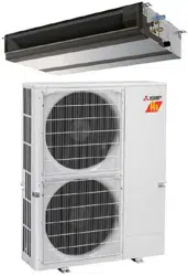
A Circuit diagram example
(Demand function)
B On-site arrangement
X, Y: Relay
8.2. Demand function (on-site modication) (Fig. 8-2)
By performing the following modication, energy consumption can be reduced to
0–100% of the normal consumption.
The demand function will be activated when a commercially available timer or the
contact input of an ON/OFF switch is added to the CNDM connector (option) on the
control board of the outdoor unit.
1 Complete the circuit as shown when using the external input adapter
(PAC-SC36NA-E). (Option)
2 By setting SW7-1 on the control board of the outdoor unit, the energy consumption
(compared to the normal consumption) can be limited as shown below.
SW7-1 SW2 SW3 Energy consumption
Demand
function
ON
OFF OFF 100%
ON OFF 75%
ON ON 50%
OFF ON 0% (Stop)
Fig. 8-2
C External input adapter
(PAC-SC36NA-E)
D Outdoor unit control board
E Max. 10 m, 33 ft
F Power supply for relay
A
SW2
SW3
Orange
1
3
Brown
Red
CNDM
Y
X
X
Y
F
B
E
C D
8.3. Refrigerant collecting (pump down)
Perform the following procedures to collect the refrigerant when moving the indoor
unit or the outdoor unit.
1 Supply power (circuit breaker).
* When power is supplied, make sure that “CENTRALLY CONTROLLED” is not
displayed on the remote controller. If “CENTRALLY CONTROLLED” is dis-
played, the refrigerant collecting (pump down) cannot be completed normally.
* Start-up of the indoor-outdoor communication takes about 3 minutes after the
power (circuit breaker) is turned on. Start the pump-down operation 3 to 4
minutes after the power (circuit breaker) is turned ON.
2 After the liquid stop valve is closed, set the SWP switch on the control board of
the outdoor unit to ON. The compressor (outdoor unit) and ventilators (indoor
and outdoor units) start operating and refrigerant collecting operation begins.
LED1 and LED2 on the control board of the outdoor unit are lit.
* Only set the SWP switch (push-button type) to ON if the unit is stopped.
However, even if the unit is stopped and the SWP switch is set to ON less
than 3 minutes after the compressor stops, the refrigerant collecting operation
cannot be performed. Wait until compressor has been stopped for 3 minutes
and then set the SWP switch to ON again.
3 Because the unit automatically stops in about 2 to 3 minutes when the refriger-
ant collecting operation is completed (LED1 off, LED2 lit), be sure to quickly
close the gas stop valve. If LED1 is lit and LED2 is off and the outdoor unit is
stopped, refrigerant collection is not properly performed. Open the liquid stop
valve completely, and then repeat step 2 after 3 minutes have passed.
* If the refrigerant collecting operation has been completed normally (LED1 off,
LED2 lit), the unit will remain stopped until the power supply is turned off.
4 Turn off the power supply (circuit breaker).
* Note that when the extension piping is very long with large refrigerant amount,
it may not be possible to perform a pump-down operation. When performing
the pump-down operation, make sure that the low pressure is lowered to near
0 MPa (gauge).
Warning:
When pumping down the refrigerant, stop the compressor before disconnect-
ing the refrigerant pipes. The compressor may burst if air etc. get into it.
1 23456
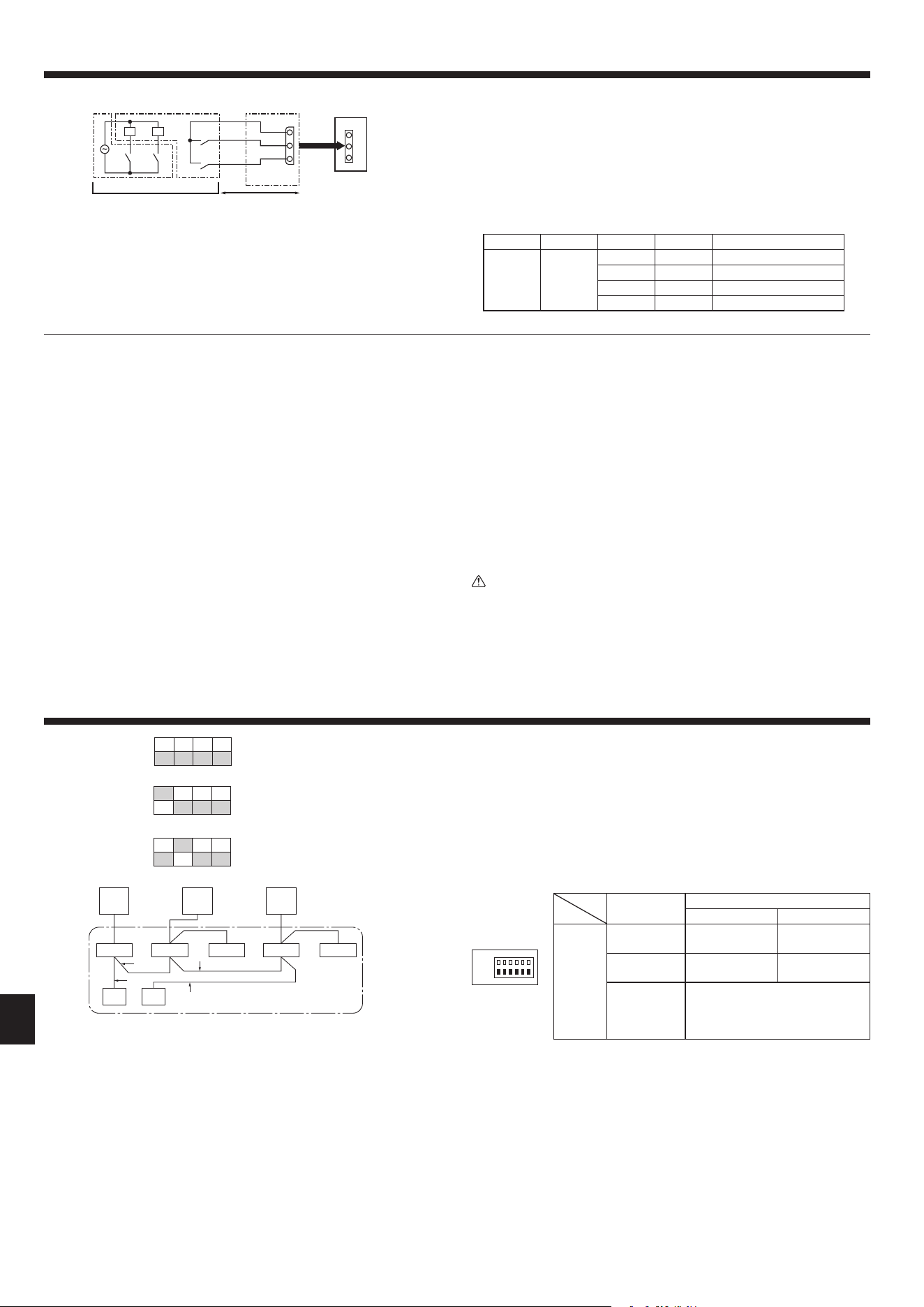
* Set the refrigerant address using the DIP switch of the outdoor unit.
1 Wiring from the Remote Control
This wire is connected to TB5 (terminal board for remote controller) of the indoor
unit (non-polar).
2 When a Different Refrigerant System Grouping is Used.
Up to 16 refrigerant systems can be controlled as one group using the slim MA
remote controller.
Note:
In single refrigerant system (twin), there is no need of wiring
2
.
A Outdoor unit
B Indoor unit
C Master remote controller
D Subordinate remote controller
E Standard 1:1 (Refrigerant address = 00)
F
Simultaneous twin (Refrigerant address = 01)
G
Simultaneous twin (Refrigerant address = 02)
E
SW 1-3 to 1-6
F
SW 1-3 to 1-6
G
SW 1-3 to 1-6
9. System control (Fig. 9-1)
Fig. 9-1
SW1
Function table
<SW1>
Function
Operation according to switch setting
ON OFF
SW1
function
settings
1 Compulsory
defrosting
Start Normal
2 Error history
clear
Clear Normal
3
4
5
6
Refrigerant
system ad-
dress setting
Settings for outdoor unit addresses
0 to 15
TB1
A GFAA E
B B B B B
D
C
TB1 TB1
TB4
TB5
TB4
TB5
TB4 TB4
TB5
TB4
1
1
2
ON
OFF
ON
OFF
ON
OFF
3 4 5 6
3 4 5 6
3 4 5 6
ON
OFF
2
8. Special Functions
en
012
Loading ...
Loading ...
Loading ...