Loading ...
Loading ...

4
5
SYMBOLOGY
Volts
Direct Current
No Load Revolutions per Minute
Wear eye protection
Read operator's manual
Do not use toothed blades
Hands Free Zone
C
US
UL Listing for Canada and U.S.
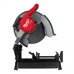
FUNCTIONAL DESCRIPTION
1. Carrying handle
2. Upper guard
3. Trigger
4. Trigger lock
5. Handle
6. Spindle lock button
7. Lower guard
8. Abrasive cut-o wheel
9. Adjustment fence
3
7
1
2
8
9
11
6
10
12
13
14
4
5
15
10. Lock lever
11. Vise clamp
12. Vise handle
13. Base
14. Hex wrench
15. Head lock down pin
16. Depth adjustment
bolt
16
ASSEMBLY
WARNING
Recharge only with the charger
specied for the battery. For spe-
cic charging instructions, read the operator’s
manual supplied with your charger and battery.
Removing/Inserting the Battery
To remove the battery, push in the release buttons
and pull the battery pack away from the tool.
WARNING
Always remove battery pack before
changing or removing accessories.
To insert the battery, slide the pack into the body
of the tool. Make sure it latches securely into place.
WARNING
Only use accessories specically
recommended for this tool. Others
may be hazardous.
To reduce the risk of injury, use only the proper
wheel for this machine. DO NOT USE ANY TYPE
OF SAW BLADE.
Removing and Installing Cut-O Wheels
Use only MILWAUKEE 14" Abrasive Cut-O Wheels,
3/32" thick with this tool. Before operating the
tool, make sure the wheel is in good condition as
described in the “Specic Safety Rules”.
To change wheels:
1. Remove the battery pack.
2. Raise the head.
3. Push up the lower guard to expose the output
spindle and clamping ange. Press in the spindle
lock button and loosen the toolless clamp (coun-
terclockwise).
4. Check the inner and outer anges to be sure they
are in good condition. Remove any nicks, burrs,
and debris from the mounting hardware, which
could cause uneven cutting pressure and result
in wheel damage.
5. Install the cut-o wheel, outer ange, and toolless
clamp onto the spindle, as shown below.
Inner ange
Abrasive cut-o wheel
Outer ange
Retaining
ring
Spindle
Toolless
clamp
6. Press in the spindle lock button and tighten the
toolless clamp back onto the spindle (clockwise).
7. Release the lower guard.
8. Before starting a cut, step back from the tool and
make a trial run to conrm that the wheel is in good
condition. Before using a new cut-o wheel, run
the tool for at least 3 minutes. Before starting work,
run the tool for at least 1 minute.
Raising and Lowering the Head
The head must be locked down for transporting and
storing the tool.
To unlock, press head down and pull out the lock
down pin.
To lock, press head down and push in the lock
down pin.
is in motion otherwise kickback may occur.
Investigate and take corrective action to eliminate
the cause of wheel binding.
•Do not restart the cutting operation in the
workpiece. Let the wheel reach full speed and
carefully re-enter the cut. The wheel may bind,
walk up or kickback if the power tool is restarted in
the workpiece.
•Support any oversized workpiece to minimize
the risk of wheel pinching and kickback. Large
workpieces tend to sag under their own weight.
Supports must be placed under the workpiece near
the line of cut and near the edge of the workpiece
on both sides of the wheel.
•
WARNING
To reduce the risk of injury, when
working in dusty situations, wear
appropriate respiratory protection or use an
OSHA compliant dust extraction solution.
• Always use common sense and be cautious when
using tools. It is not possible to anticipate every
situation that could result in a dangerous outcome.
Do not use this tool if you do not understand these
operating instructions or you feel the work is beyond
your capability; contact Milwaukee Tool or a trained
professional for additional information or training.
• Maintain labels and nameplates. These carry
important information. If unreadable or missing,
contact a MILWAUKEE service facility for a free
replacement.
•
WARNING
Some dust created by power sanding,
sawing, grinding, drilling, and other
construction activities contains chemicals known to
cause cancer, birth defects or other reproductive
harm. Some examples of these chemicals are:
• lead from lead-based paint
• crystalline silica from bricks and cement and other
masonry products, and
• arsenic and chromium from chemically-treated
lumber.
Your risk from these exposures varies, depending on
how often you do this type of work. To reduce your
exposure to these chemicals: work in a well ventilated
area, and work with approved safety equipment, such
as those dust masks that are specially designed to
lter out microscopic particles.
SPECIFICATIONS
Cat. No. ..................................................... 2990-20
Volts.............................................................. 18 DC
Battery Type .................................................M18™
Charger Type................................................M18™
No Load RPM ..................................................4000
Wheel Size ........................................................ 14"
Min. Wheel RPM Rating ..................................4300
Wheel Thickness ............................................ 3/32"
Arbor Hole Size ................................................... 1"
Max. Capacities at 90
°
Rectangular Stock .........................4-1/2" x 5-1/8"
Square Tubing ....................... 4-11/16" x 4-11/16"
O.D. Pipe .......................................................... 5"
Max. Capacities at 45
°
Rectangular Stock .............................4" x 4-1/16"
Sqaure Tubing ........................................... 4" x 4"
O.D. Pipe ....................................................... 4.5"
Recommended Ambient
Operating Temperature ......................0°F to 125°F
Adjusting the Depth of the Cut
The depth adjustment bolt can be adjusted to change
the depth of cut. When adjusted properly, the depth
adjustment bolt prevents the cut-off wheel from
contacting the surface under the base during cutting.
Cut-o wheels wear down as they are used and the
depth of cut may need to be increased.
To adjust the depth of cut:
1. Remove the battery pack.
2. Use a suitable wrench to loosen the hex nut.
3. Adjust the depth adjustment bolt to the desired
height.
4. Tighten the hex nut.
Supporting the Workpiece and Adjusting
the Vise and Fence System
The adjustable vise and fence
Center
line
Cutting
area
Typical
materials
system holds the workpiece in
the desired position. The vise
plate and fence can be moved
backward or forward and can be
adjusted to any angle between
90° and 45°.
When adjusting the system, the
vise and fence should be posi-
tioned so the centerline of the
wheel hub is in line with or behind
the centerline of the workpiece,
toward the rear of the tool. The
workpiece should be resting
ush with the base of the cut-o
machine.
Vise
handle
Lock
lever
Vise
plate
Fence
Adjustable
handle
Thumb
screw
To adjust the fence position:
1. Turn the adjustable handle counterclockwise to
loosen.
2. Unscrew and remove the fence thumbscrew
completely.
3. Reposition the fence to the desired position.
4. Reinstall the fence thumbscrew into one of the four
threaded holes located on the base.
NOTE: Ensure the adjustable handle and thumb-
screw are tightly in place before cutting.
To adjust the fence angle:
1. Turn the adjustable handle counterclockwise to
loosen.
2. Unscrew the thumb screw to loosen.
3. Rotate the fence to the desired angle, aligning
with the measurements inscribed on the fence.
4. Turn the adjustable handle clockwise to tighten.
5. Screw the thumbscrew tightly in place.
NOTE: Ensure the adjustable handle and thumb-
screw are tightly in place before cutting.
Loading ...
Loading ...
Loading ...