
Backup Camera
User Manual
UD04678B-B


User Manual
COPYRIGHT ©2018 Hangzhou Hikvision Digital Technology Co., Ltd.
ALL RIGHTS RESERVED.
Any and all information, including, among others, wordings, pictures, graphs are the
properties of Hangzhou Hikvision Digital Technology Co., Ltd. or its subsidiaries (hereinafter
referred to be “Hikvision”). This user manual (hereinafter referred to be “the Manual”) cannot
be reproduced, changed, translated, or distributed, partially or wholly, by any means, without the
prior written permission of Hikvision. Unless otherwise stipulated, Hikvision does not make any
warranties, guarantees or representations, express or implied, regarding to the Manual.
About this Manual
This Manual is applicable to Backup Camera.
The Manual includes instructions for using and managing the product. Pictures, charts, images
and all other information hereinafter are for description and explanation only. The information
contained in the Manual is subject to change, without notice, due to firmware updates or other
reasons. Please find the latest version in the company website (http:// overseas.hikvision.com/
en/).
Please use this user manual under the guidance of professionals.
Trademarks Acknowledgement
and other Hikvision’s trademarks and logos are the properties of Hikvision in
various jurisdictions. Other trademarks and logos mentioned below are the properties of
their respective owners.
Legal Disclaimer
TO THE MAXIMUM EXTENT PERMITTED BY APPLICABLE LAW, THE PRODUCT DESCRIBED, WITH
ITS HARDWARE, SOFTWARE AND FIRMWARE, IS PROVIDED “AS IS”, WITH ALL FAULTS AND
ERRORS, AND HIKVISION MAKES NO WARRANTIES, EXPRESS OR IMPLIED, INCLUDING WITHOUT
LIMITATION, MERCHANTABILITY, SATISFACTORY QUALITY, FITNESS FOR A PARTICULAR
PURPOSE, AND NON-INFRINGEMENT OF THIRD PARTY. IN NO EVENT WILL HIKVISION, ITS
DIRECTORS, OFFICERS, EMPLOYEES, OR AGENTS BE LIABLE TO YOU FOR ANY SPECIAL,
CONSEQUENTIAL, INCIDENTAL, OR INDIRECT DAMAGES, INCLUDING, AMONG OTHERS,
DAMAGES FOR LOSS OF BUSINESS PROFITS, BUSINESS INTERRUPTION, OR LOSS OF DATA OR
DOCUMENTATION, IN CONNECTION WITH THE USE OF THIS PRODUCT, EVEN IF HIKVISION HAS
BEEN ADVISED OF THE POSSIBILITY OF SUCH DAMAGES.
REGARDING TO THE PRODUCT WITH INTERNET ACCESS, THE USE OF PRODUCT SHALL BE
WHOLLY AT YOUR OWN RISKS. HIKVISION SHALL NOT TAKE ANY RESPONSIBILITES FOR
ABNORMAL OPERATION, PRIVACY LEAKAGE OR OTHER DAMAGES RESULTING FROM CYBER
ATTACK, HACKER ATTACK, VIRUS INSPECTION, OR OTHER INTERNET SECURITY RISKS;
HOWEVER, HIKVISION WILL PROVIDE TIMELY TECHNICAL SUPPORT IF REQUIRED.
SURVEILLANCE LAWS VARY BY JURISDICTION. PLEASE CHECK ALL RELEVANT LAWS IN YOUR
JURISDICTION BEFORE USING THIS PRODUCT IN ORDER TO ENSURE THAT YOUR USE CONFORMS
THE APPLICABLE LAW. HIKVISION SHALL NOT BE LIABLE IN THE EVENT THAT THIS PRODUCT IS
USED WITH ILLEGITIMATE PURPOSES.
IN THE EVENT OF ANY CONFLICTS BETWEEN THIS MANUAL AND THE APPLICABLE LAW, THE LATER
PREVAILS.
1

Regulatory Information FCC Information
Please take attention that changes or modification not expressly approved by the party
responsible for compliance could void the user’s authority to operate the equipment. FCC
compliance: This equipment has been tested and found to comply with the limits for a Class
B digital device, pursuant to part 15 of the FCC Rules. These limits are designed to provide
reasonable protection against harmful interference in a residential installation.
This equipment generates, uses and can radiate radio frequency energy and, ifnot
installed and used in accordance with the instructions, may cause harmful interference to
radio communications. However, there is no guarantee that interference will not occur in a
particular installation. If this equipment does cause harmful interference to radio or
television reception, which can be determined by turning the equipment off and on, the
user is encouraged to try to correct the interference by one or more of the following
measures:
—Reorient or relocate the receiving antenna.
—Increase the separation between the equipment and receiver.
—Connect the equipment into an outlet on a circuit different from that to which the
receiver is connected.
—Consult the dealer or an experienced radio/TV technician for help.
FCC Conditions
This device complies with part 15 of the FCC Rules. Operation is subject to the following two
conditions:
1. This device may not cause harmful interference.
2. This device must accept any interference received, including interference that may cause
undesired operation.
EU Conformity Statement
This product and - if applicable - the supplied accessories too are marked with "CE"
and comply therefore with the applicable harmonized European standards listed
under the EMC Directive 2014/30/EU, the RoHS Directive 2011/65/EU.
2012/19/EU (WEEE directive): Products marked with this symbol cannot be disposed of
as unsorted municipal waste in the European Union. For proper recycling, return this
product to your local supplier upon the purchase of equivalent new equipment,
or dispose of it at designated collection points. For more information see: www.recyclethis. info
2006/66/EC and its amendment¬2013/56/EU (battery directive): This product
contains a battery that cannot be disposed of as unsorted municipal waste in the
European Union. See the product documentation for specific battery information.
The battery is marked with this symbol, which may include lettering to indicate
cadmium (Cd), lead (Pb), or mercury (Hg). For proper recycling, return the battery to your
supplier or to a designated collection point. For more information see: www.recyclethis.info
2
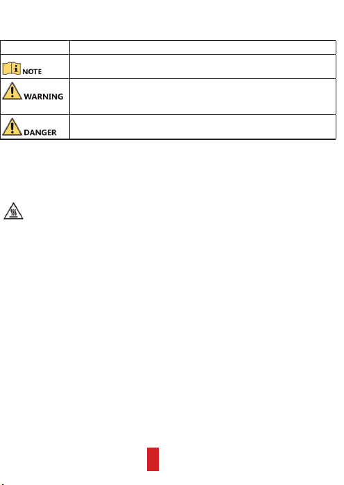
Symbol Conventions
The symbols that may be found in this document are defined as follows.
Symbol Description
Provides additional information to emphasize or supplement
important points of the main text.
Indicates a potentially hazardous situation, which if not avoided,
could result in equipment damage, data loss, performance
degradation, or unexpected results.
Indicates a hazard with a high level of risk, which if not avoided, will
result in death or serious injury.
Preventive and Cautionary Tips
Before connecting and operating your device, please be advised of the following tips:
Avoid touching the device with your bare hands when it is working. When the
temperature of working environment is higher than 50
℃
, you may scald
yourself by touching the shell of the device.
• Proper configuration of all passwords and other security settings are the
responsibility of the installer and/or end-user.
• In the use of the product, you must be in strict compliance with the electrical safety
regulations of the nation and region. Please refer to technical specifications for
detailed information.
• Input voltage should meet both the SELV (Safety Extra Low Voltage) and the
Limited Power Source with 100 to 240 VAC, 12 VDC, or 6 to 16 VDC according to the
IEC60950-1 standard. Please refer to technical specifications for detailed
information.
• Do not connect several devices to one power adapter as adapter overload may
cause over-heating or a fire hazard.
• Please make sure that the plug is firmly connected to the power socket.
• If smoke, odor or noise rise from the device, turn off the power at once and
unplug the power cable, and then please contact the service center.
• Ensure environmental conditions meet factory specifications.
• Ensure unit is properly secured to a rack or shelf. Major shocks or jolts to the unit as
a result of dropping it may cause damage to the sensitive electronics within the unit.
• Power down the device before connecting and disconnecting accessories and
peripherals.
• Improper use or replacement of the battery may result in hazard of explosion.
Replace with the same or equivalent type only. Dispose of used batteries according to
the instructions provided by the battery manufacturer.
3
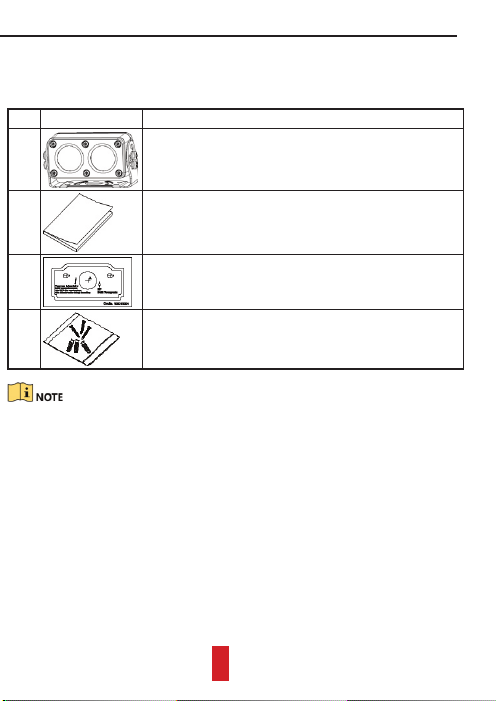
Chapter 1 Checking Package
Ensure the backup camera in package is in good condition and all assembly parts are
included.
Table 1 Package List
No. Figure Description
1 • I-type backup camera: a main body and a bracket.
• II-type backup camera: a main body, a bracket, and
an enclosure.
2
One user manual.
3
A piece of drill template.
4
One screw package.
The package list varies with the backup camera model.
4
Chapter 2 Product Introduction
2.1 Key Features
• Day-to-night feature for 24-hour monitoring.
• Wide-angle lens.
• Electronic shutter.
• Electronic gain.
• IP68.
• Aviation plug and image stabilization.
• Adopts metal material.
2.2 Structure and Components
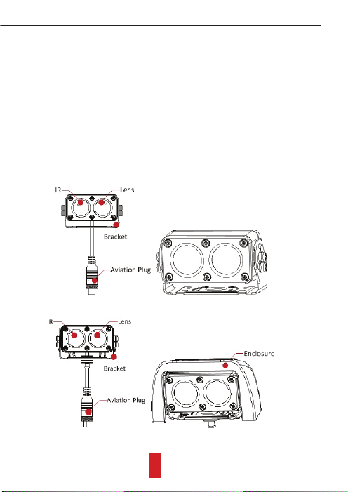
2.2.1 Overall View
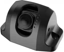
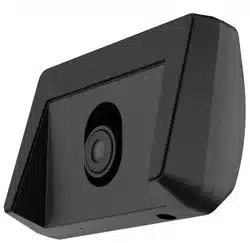
The overall view of I-type and II-type cameras are shown in Figure 1 and Figure 2.
Figure 1 I-Type Backup Camera
Figure 2 II-Type Backup Camera
5

2.2.2 Aviation Plug
The aviation plug design increases the image stabilization. It offers two types of pin
sequence as show in Figure 3. Connect the aviation plug with a suitable cable.
Corresponded with mobile environment, backup camera power supply adopts wide
voltage range (6 to 16 VDC).
Figure 3 Aviation Plug Pin Sequences
6
Chapter 3 Installation
Ensure the installation position strong enough to support four times the weight of
backup camera.
3.1 Installing I-Type Backup Camera
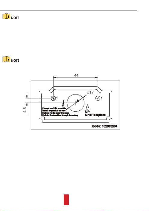
Step 1 Paste the drill template to the desired plate on vehicle rear.
Step 2 The two Hole 1 are used to fix the bracket. Drill them with a 5.5 mm drill and
insert a metal anchor in each Hole 1.
If you want to route cable inside the vehicle, you have to drill a cable hole according
to Hole A.
Figure 1 Drill Template
Step 3 Aim the holes in bracket with the two Hole 1.
7
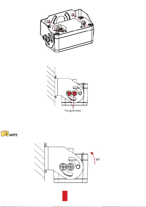
Step 4 To fix bracket on the vehicle, thread one PA4*25 screw into each metal
anchor through the bracket.
Figure 2 Thread Screws
Step 5 Loosen the two fixing screws.
Figure 3 Loosen Fixing Screws
Step 6 Rotate the main body to a desired view and fasten the fixing screws to finish
installation.
The rotatable angle is up to 90 degree, as shown in Figure 4.
Figure 4 Rotate Main Body
8
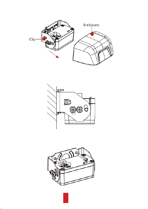
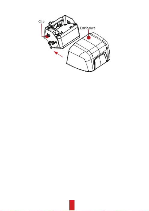
3.2 Installing II-Type Backup Camera
Step 1 Press the clips at the sides of enclosure and separate the enclosure from the
main body along the direction shown in Figure 1.
Figure 1 Separate Enclosure and Main Body
Step 2 Drill in vehicle rear and aim the holes in bracket with drill template, for
detailed steps, refer to step 1 to 3 of section 3.1.
Figure 2 Drill Holes
Step 3 To fix bracket on vehicle, thread one PA4*25 screw into each metal anchor
through bracket.
Figure 3 Thread Screws
9
Step 4 Assemble enclosure to main body along direction shown in Figure 4 to finish
installation.
Figure 4 Assemble Enclosure
10