
TA10050 / TA10051
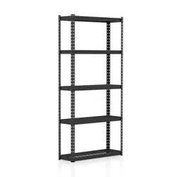
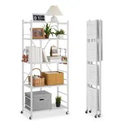
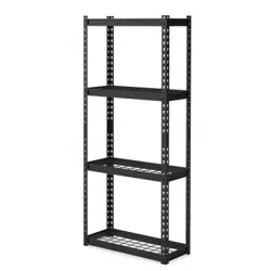
4-Tier Wire Shelf
Étagères Métalliques à 4 Niveaux
THIS INSTRUCTION BOOKLET CONTAINS IMPORTANT SAFETY INFORMATION. PLEASE READ AND KEEP FOR FUTURE REFERENCE.
If you're having difficulty, our friendly
customer team is always here to help.
USA office: Fontana AUS office: Truganina
GBR office: Ipswich FRA office: Saint Vigor d'Ymonville
AUS:cs.au@costway.com
GBR:cs.uk@costway.com
FRA:cs.fr@costway.com
Before You Start
Please read all instructions carefully.
Retain instructions for future reference.
Separate and count all parts and hardware.
Read through each step carefully and follow the proper order.
We recommend that, where possible, all items are assembled near to the area in
which they will be placed in use, to avoid moving the product unnecessarily once
assembled.
Always place the product on a flat, steady and stable surface.
Keep all small parts and packaging materials for this product away from babies
and children as they potentially pose a serious choking hazard.
FR
Veuillez lire attentivement toutes les instructions.
Conservez les instructions pour vous y référer ultérieurement.
Vérifiez toutes les pièces et les accessoires.
Lisez attentivement chaque étape et suivez l'ordre correct.
Nous recommandons que, dans la mesure du possible, tous les produits
soient assemblés à proximité de la zone où ils seront utilisés, afin d'éviter tout
déplacement inutile du produit une fois assemblé.
Placez toujours le produit sur une surface plane et stable.
Conservez toutes les petites pièces de ce produit et les matériaux d'emballage
hors de portée des bébés et des enfants, car ils pourraient présenter un risque
d'étouffement.
Avant de Commencer
ASSEMBLY INSTRUCTIONS
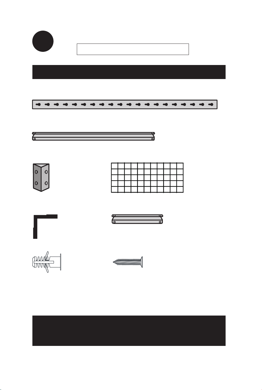
LIST OF PARTS
WARNING
EN
The only tool you require is a MALLET
8x Keyhole Uprights
8x Long Shelf Supports
4x Leg Joiners
4 x Wire Shelf
8x Plastic Feet
Anchors Screws
8x Short Shelf Supports
Handle cut metal edges carefully.
EN
02 03
Before You Start
Please read all instructions carefully.
Retain instructions for future reference.
Separate and count all parts and hardware.
Read through each step carefully and follow the proper order.
We recommend that, where possible, all items are assembled near to the area in
which they will be placed in use, to avoid moving the product unnecessarily once
assembled.
Always place the product on a flat, steady and stable surface.
Keep all small parts and packaging materials for this product away from babies
and children as they potentially pose a serious choking hazard.
FR
Veuillez lire attentivement toutes les instructions.
Conservez les instructions pour vous y référer ultérieurement.
Vérifiez toutes les pièces et les accessoires.
Lisez attentivement chaque étape et suivez l'ordre correct.
Nous recommandons que, dans la mesure du possible, tous les produits
soient assemblés à proximité de la zone où ils seront utilisés, afin d'éviter tout
déplacement inutile du produit une fois assemblé.
Placez toujours le produit sur une surface plane et stable.
Conservez toutes les petites pièces de ce produit et les matériaux d'emballage
hors de portée des bébés et des enfants, car ils pourraient présenter un risque
d'étouffement.
Avant de Commencer
ASSEMBLY INSTRUCTIONS
LIST OF PARTS
WARNING
EN
The only tool you require is a MALLET
8x Keyhole Uprights
8x Long Shelf Supports
4x Leg Joiners
4 x Wire Shelf
8x Plastic Feet
Anchors Screws
8x Short Shelf Supports
Handle cut metal edges carefully.
EN
02 03
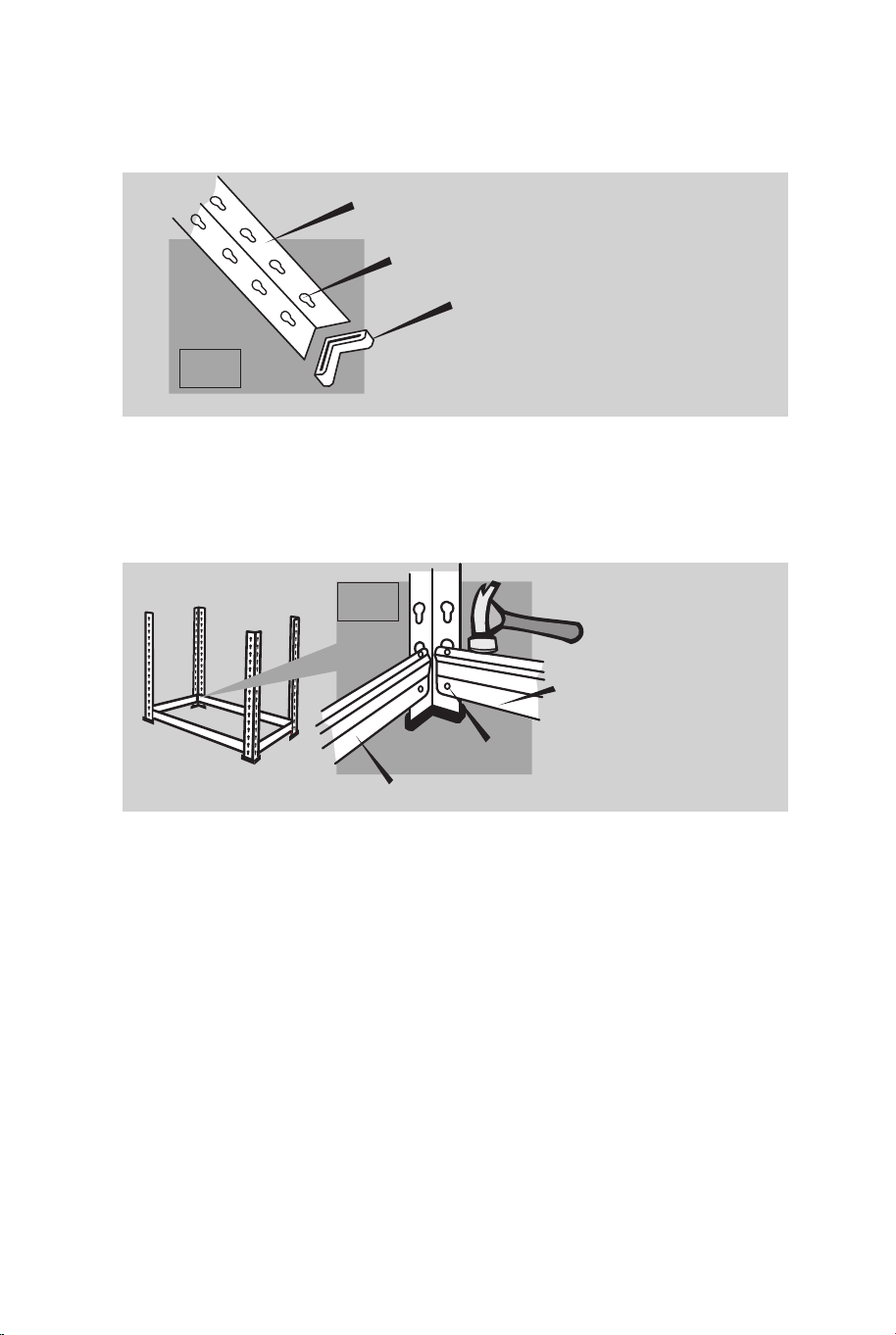
1. Attach a Plastic Foot to one end of 4 of the Keyhole Uprights.
NOTE: Ensure keyholes are the correct way up.(Pic 1)
2. Fit 2 Short Shelf Supports and 2 Long Shelf Supports to the
bottom boles (for maximum strength) of 4 Keyhole Uprights by
slotting the Keylock Pins in the Supports into the Uprights and
tapping firmly with a hammer to seat in place (Pic 2).
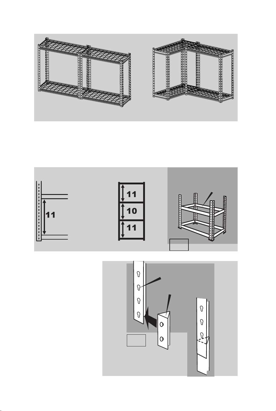
4. Fit Long and Short Shelf Supports where you want the 2nd Shelf
to be positioned. These Supports must not be in the top 2 holes of
the Keyhole Upright. (Pic 3)
(We have shelf position recommendations listed below).
5. Fit 4 Leg Joiners
to the bottom holes
in each of the 4
remaining Keyhole
Uprights. Leg Joiner
MUST be this way
up.(Pic 4 )
NUMBER OF HOLES
ON KEYHOLE
UPRIGHT BETWEEN
SHELF SUPPORTS
3. (GO TO 4 IF YOU ARE NOT ASSEMBLING AS A WORKBENCH)
a) Fit 2 Short Shelf Supports and 2 Long Shelf Supports for the to
the top of the Workbench into the holes at the top of the Keyhole
Uprights.
b) Assemble the remaining Keyhole Uprights and Long and Short
Shelf Supports to maker either a Straight Workbench or a Corner
Workbench, using the same method as above.
c) Install Wire Shelf.
d) Bolt the 2 halves of the Workbench together if needed (nuts and
bolts not supplied).
KEYHOLE UPRIGHT
LONG SHELF
SUPPORT
KEYHOLES TO BE THIS WAY UP
PLASTIC FOOT
STRAIGHT WORKBENCH CORNER WORKBENCH
SHELF POSITION RECOMMENDATIONS
FIT TO BOTTOM HOLES
SHORT SHELF SUPPORT
Pic 1
Pic 2
SHELE SUPPORTSFOR
2ND SHELF
Pic 3
Pic 4
KEYHOLES TO BE
THIS WAY UP
LEG JOINER MUST
BE THIS WAY UP
04 05
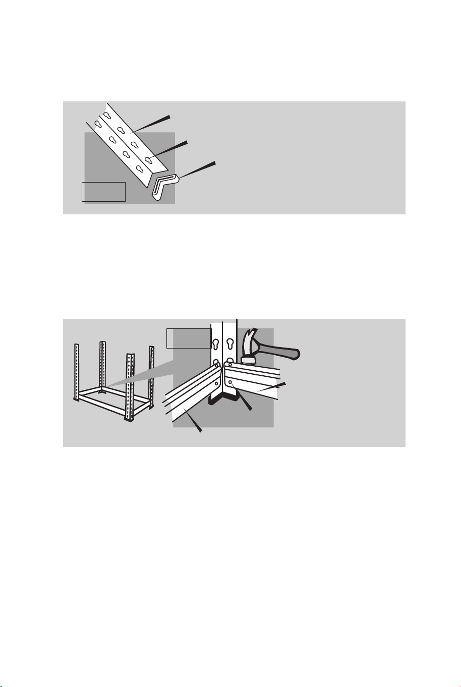
1. Attach a Plastic Foot to one end of 4 of the Keyhole Uprights.
NOTE: Ensure keyholes are the correct way up.(Pic 1)
2. Fit 2 Short Shelf Supports and 2 Long Shelf Supports to the
bottom boles (for maximum strength) of 4 Keyhole Uprights by
slotting the Keylock Pins in the Supports into the Uprights and
tapping firmly with a hammer to seat in place (Pic 2).
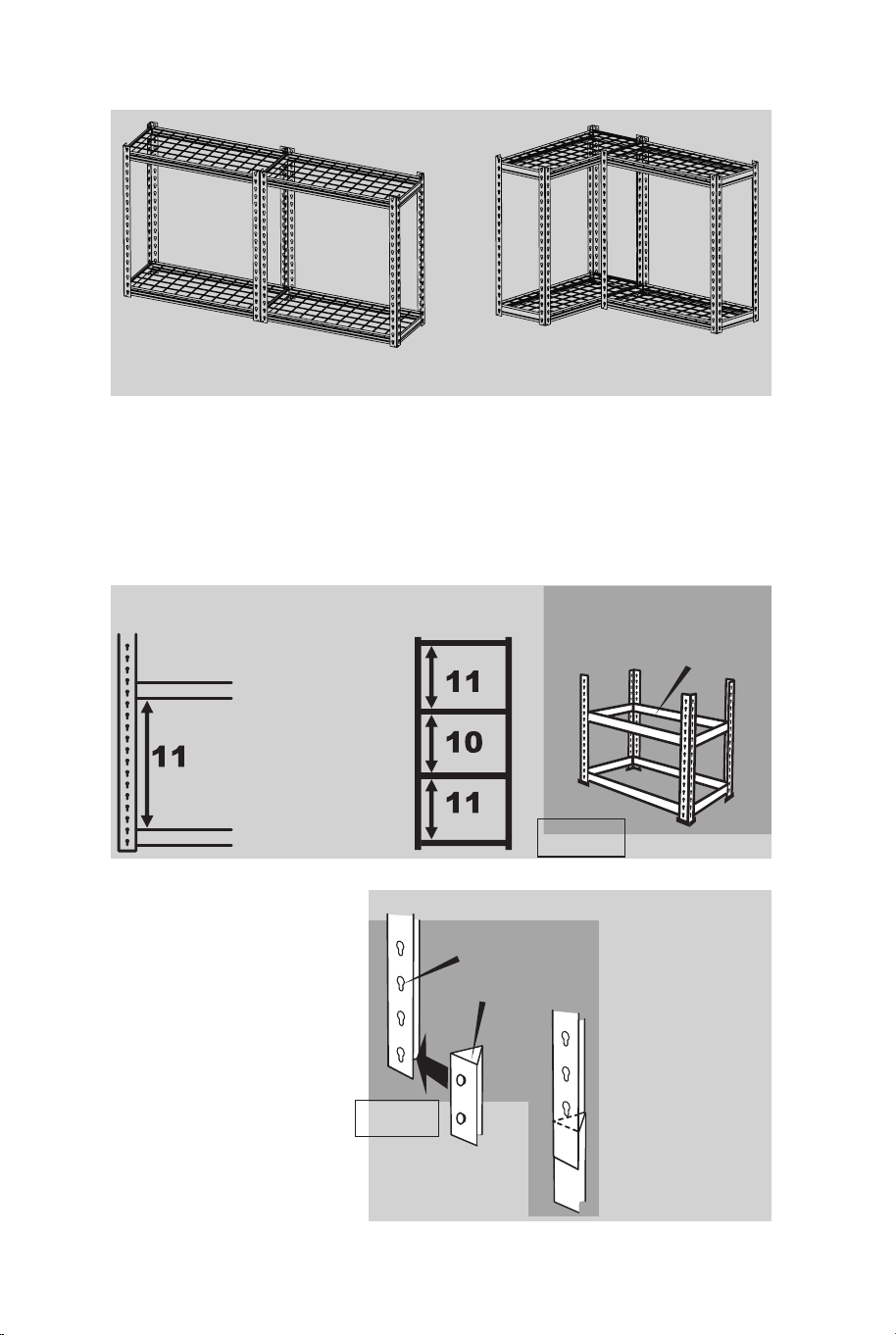
4. Fit Long and Short Shelf Supports where you want the 2nd Shelf
to be positioned. These Supports must not be in the top 2 holes of
the Keyhole Upright. (Pic 3)
(We have shelf position recommendations listed below).
5. Fit 4 Leg Joiners
to the bottom holes
in each of the 4
remaining Keyhole
Uprights. Leg Joiner
MUST be this way
up.(Pic 4 )
NUMBER OF HOLES
ON KEYHOLE
UPRIGHT BETWEEN
SHELF SUPPORTS
3. (GO TO 4 IF YOU ARE NOT ASSEMBLING AS A WORKBENCH)
a) Fit 2 Short Shelf Supports and 2 Long Shelf Supports for the to
the top of the Workbench into the holes at the top of the Keyhole
Uprights.
b) Assemble the remaining Keyhole Uprights and Long and Short
Shelf Supports to maker either a Straight Workbench or a Corner
Workbench, using the same method as above.
c) Install Wire Shelf.
d) Bolt the 2 halves of the Workbench together if needed (nuts and
bolts not supplied).
KEYHOLE UPRIGHT
LONG SHELF
SUPPORT
KEYHOLES TO BE THIS WAY UP
PLASTIC FOOT
STRAIGHT WORKBENCH CORNER WORKBENCH
SHELF POSITION RECOMMENDATIONS
FIT TO BOTTOM HOLES
SHORT SHELF SUPPORT
Pic 1
Pic 2
SHELE SUPPORTSFOR
2ND SHELF
Pic 3
Pic 4
KEYHOLES TO BE
THIS WAY UP
LEG JOINER MUST
BE THIS WAY UP
04 05

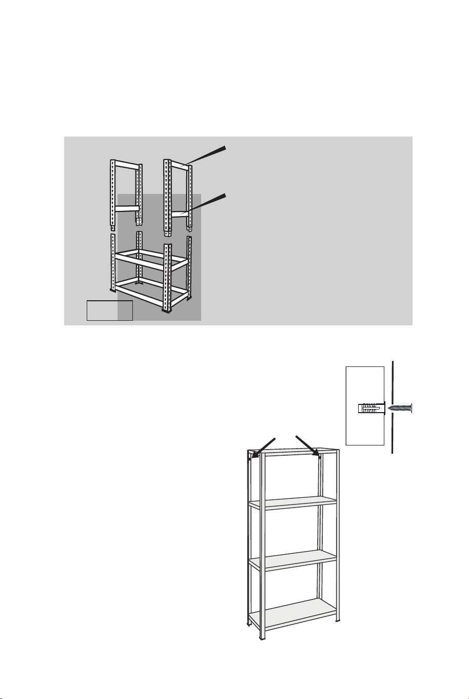
6.To make one side of the top half of the Storage Unit: Fit 2 Short
Shelf Supports to 2 Keyhole Uprights. Fit the top Support first. It
must be located in the 2 holes of the Upright. Then fit the 3rd
Support in your chosen position.(Pic 5)
Repeat this procedure to make the second side.
8.Fit the 2 Long Shelf Supports at the 3rd shelf
position and then fit the last 2 Long Shelf
Supports at the top shelf position.
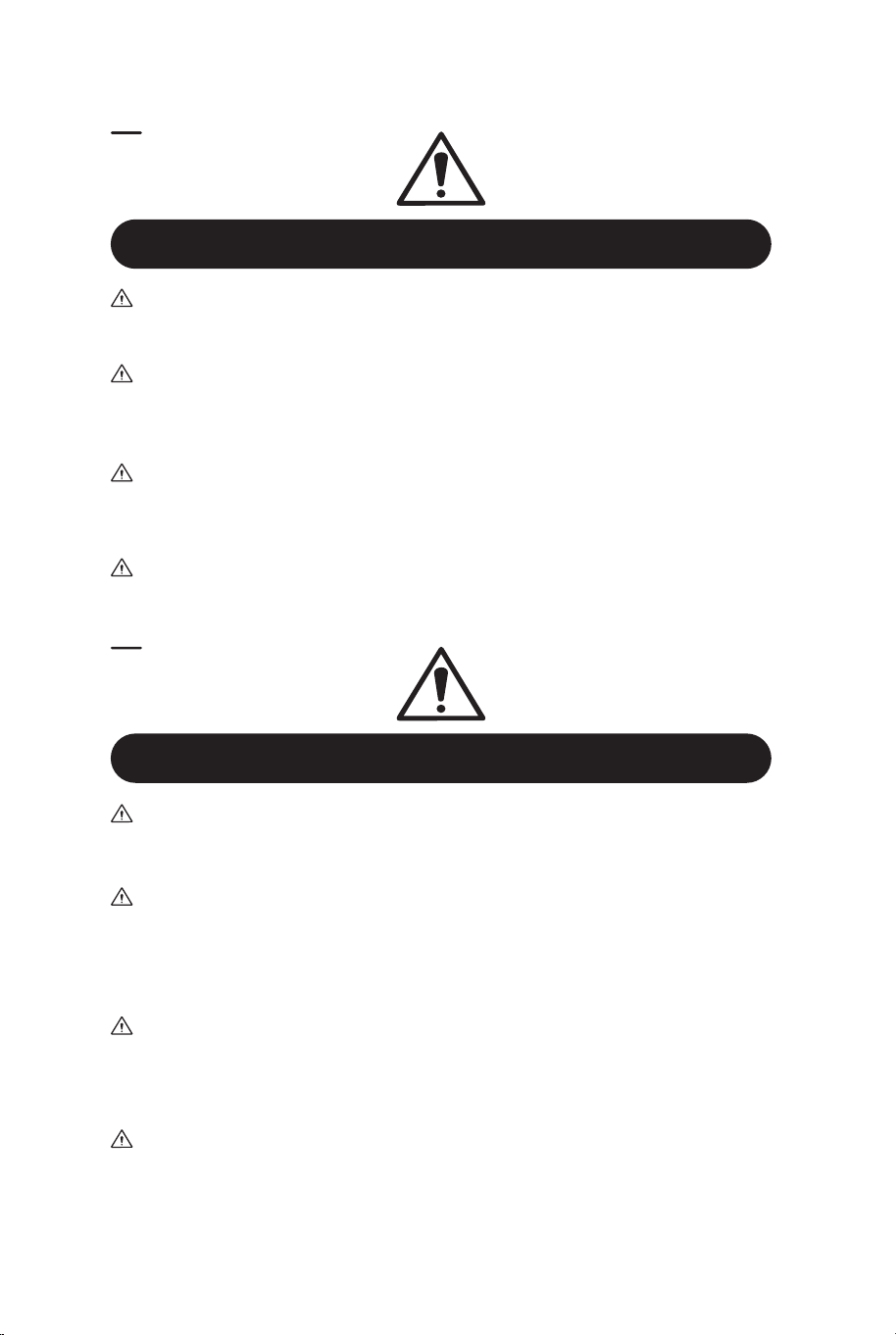
9.Place the 4 Wire Shelf onto
the 4 Shelf supports and fit the
last 4 Plastic Feet to the tops of
the Uprights.
10.Expansion tubes and screws
hold the shelves to the wall.
7.Fit these 2 top halves to
the bottom half using the
Leg Joiners.(Pic 5)
TOP SHELF SUPPORT
3RD SHELF SUPPORT
Pic 5
INSTRUCTIONS DE MONTAGE
LISTE DES PIÈCES
AVERTISSEMENT
Le seul outil dont vous avez besoin est un MALLET
8x Poteaux en trou de serrure
8x Supports d'étagères longues
4 x Jonctions
de pieds
4 x Étagères en fil métallique
8x Pieds en
Plastique
Ancrages Vis
8x Supports d'étagères courtes
Manipulez les bords métalliques coupés avec précaution.
FR
06 07

6.To make one side of the top half of the Storage Unit: Fit 2 Short
Shelf Supports to 2 Keyhole Uprights. Fit the top Support first. It
must be located in the 2 holes of the Upright. Then fit the 3rd
Support in your chosen position.(Pic 5)
Repeat this procedure to make the second side.
8.Fit the 2 Long Shelf Supports at the 3rd shelf
position and then fit the last 2 Long Shelf
Supports at the top shelf position.
9.Place the 4 Wire Shelf onto
the 4 Shelf supports and fit the
last 4 Plastic Feet to the tops of
the Uprights.
10.Expansion tubes and screws
hold the shelves to the wall.
7.Fit these 2 top halves to
the bottom half using the
Leg Joiners.(Pic 5)
TOP SHELF SUPPORT
3RD SHELF SUPPORT
Pic 5
INSTRUCTIONS DE MONTAGE
LISTE DES PIÈCES
AVERTISSEMENT
Le seul outil dont vous avez besoin est un MALLET
8x Poteaux en trou de serrure
8x Supports d'étagères longues
4 x Jonctions
de pieds
4 x Étagères en fil métallique
8x Pieds en
Plastique
Ancrages Vis
8x Supports d'étagères courtes
Manipulez les bords métalliques coupés avec précaution.
FR
06 07
1. Fixez un pied en plastique à l'une des extrémités de 4 des poteaux
en forme de trou de serrure. REMARQUE: Veiller à ce que les trous
de serrure soient orientés correctement vers le haut (photo 1).
2. Fixez 2 supports d'étagère courts et 2 supports d'étagère longs
aux trous inférieurs (pour une résistance maximale) de 4 poteaux en
trou de serrure en insérant les goupilles de verrouillage des supports
dans les poteaux et en tapant fermement à l'aide d'un marteau pour
les mettre en place (photo 2).
4. Installez les supports d'étagère longs et courts à l'endroit où vous
souhaitez placer la deuxième étagère. Ces supports ne doivent pas
se trouver dans les deux trous supérieurs du montant en trou de
serrure. (Photo 3)
(Vous trouverez ci-dessous des recommandations concernant la
position des étagères).
5. Fixez 4 joints de
pied aux trous
inférieurs de chacun
des 4 montants en
forme de trou de
serrure restants. Le
joint de pied DOIT
être orienté vers le
haut (photo 4).
NOMBRE DE TROUS
SUR LE MONTANT EN
TROU DE SERRURE
ENTRE LES SUPPORTS
D'ÉTAGÈRE
3. (PASSEZ AU POINT 4 SI VOUS N'ASSEMBLEZ PAS L'ÉTABLI)
a) Insérez 2 supports d'étagère courts et 2 supports d'étagère longs
pour le haut de l'établi dans les trous situés en haut des montants en
forme de trou de serrure.
b) Assemblez les montants en trou de serrure restants et les
supports d'étagère longs et courts pour fabriquer un établi droit ou
un établi d'angle, en utilisant la même méthode que ci-dessus.
c) Installez l'étagère en fil métallique.
d) Vissez les deux moitiés de l'établi ensemble si nécessaire (les
écrous et les boulons ne sont pas fournis).
POTEAUX EN TROU DE SERRURE
SUPPORT
D'ÉTAGÈRE LONG
LES TROUS DE SERRURE DOIVENT
ÊTRE ORIENTÉS VERS LE HAUT
PIED EN PLASTIQUE
ÉTABLI DROIT ÉTABLI D'ANGLE
RECOMMANDATIONS CONCERNANT
LA POSITION DES ÉTAGÈRES
S'ADAPTE AUX TROUS
DU BAS
SUPPORT D'ÉTAGÈRE COURT
Photo
1
Photo 2
SUPPORTS DE TÔLE
POUR LA DEUXIÈME
ÉTAGÈRE
Photo 3
LES TROUS DE SERRURE
DOIVENT ÊTRE ORIENTÉS
VERS LE HAUT
LE JOINT DE PIED DOIT ÊTRE
ORIENTÉ VERS LE HAUT
Photo 4
08 09
Instructions De Retour / Réclamation De Dommages
Dans le cas où un retour est requis, l'article doit être retourné dans sa boîte
d'origine. Sans cela, votre retour ne sera pas accepté.
NE PAS jeter la boîte/l'emballage d'origine.
Prenez une photo des marquages de la boîte.
Prenez une photo des dommages (le cas échéant).
Envoyez-nous un e-mail avec les images demandées.
Une photo des marquages (texte) sur le côté de la boîte est requise au cas où
une pièce serait nécessaire pour le remplacement. Cela aide notre personnel à
identifier votre numéro de produit pour s'assurer que vous recevez les bonnes
pièces.
Une photo des dommages est toujours requise pour déposer une réclamation et
obtenir rapidement votre remplacement ou votre remboursement. Assurez-vous
d'avoir la boîte même si elle est endommagée.
Envoyez-nous un e-mail directement depuis le marché où votre article a été
acheté avec les images ci-jointes et une description de votre réclamation.
FR
In case a return is required, the item must be returned in original box. Without this
your return will not be accepted.
DO NOT discard the box / original packaging.
Take a photo of the box markings.
Take a photo of the damaged part (if applicable).
Send us an email with the images requested.
A photo of the markings (text) on the side of the box is required in case a part is
needed for replacement. This helps our staff identify your product number to
ensure you receive the correct parts.
A photo of the damage is always required to file a claim and get your replacement
or refund processed quickly. Please make sure you have the box even if it is
damaged.
Email us directly from marketplace where your item was purchased with the
attached images and a description of your claim.
EN
Return / Damage Claim Instructions
Instructions De Retour / Réclamation De Dommages
6. Pour réaliser un côté de la moitié supérieure de l'unité de
rangement : Fixez 2 supports d'étagère courts à 2 montants en trou
de serrure. Montez d'abord le support supérieur. Il doit être placé
dans les deux trous du montant. Montez ensuite le troisième support
à l'endroit que vous avez choisi (photo 5).
Répétez cette procédure pour le deuxième côté.
8. Placez les 2 supports d'étagère longs à la
troisième position de l'étagère, puis placez les 2
derniers supports d'étagère longs à la position
de l'étagère supérieure.
9. Placez les 4 étagères en fil
métallique sur les 4 supports
d'étagère et fixez les 4 derniers
pieds en plastique au sommet
des montants.
10. Des tubes d'expansion et
des vis maintiennent les
étagères au mur.
7.Fixez ces deux moitiés
supérieures à la moitié
inférieure à l'aide des
joints de pied.(Photo 5)
SUPPORT DE L'ÉTAGÈRE
SUPÉRIEURE
3ÈME SUPPORT D'ÉTAGÈRE
Photo 5
10 11
Instructions De Retour / Réclamation De Dommages
Dans le cas où un retour est requis, l'article doit être retourné dans sa boîte
d'origine. Sans cela, votre retour ne sera pas accepté.
NE PAS jeter la boîte/l'emballage d'origine.
Prenez une photo des marquages de la boîte.
Prenez une photo des dommages (le cas échéant).
Envoyez-nous un e-mail avec les images demandées.
Une photo des marquages (texte) sur le côté de la boîte est requise au cas où
une pièce serait nécessaire pour le remplacement. Cela aide notre personnel à
identifier votre numéro de produit pour s'assurer que vous recevez les bonnes
pièces.
Une photo des dommages est toujours requise pour déposer une réclamation et
obtenir rapidement votre remplacement ou votre remboursement. Assurez-vous
d'avoir la boîte même si elle est endommagée.
Envoyez-nous un e-mail directement depuis le marché où votre article a été
acheté avec les images ci-jointes et une description de votre réclamation.
FR
In case a return is required, the item must be returned in original box. Without this
your return will not be accepted.
DO NOT discard the box / original packaging.
Take a photo of the box markings.
Take a photo of the damaged part (if applicable).
Send us an email with the images requested.
A photo of the markings (text) on the side of the box is required in case a part is
needed for replacement. This helps our staff identify your product number to
ensure you receive the correct parts.
A photo of the damage is always required to file a claim and get your replacement
or refund processed quickly. Please make sure you have the box even if it is
damaged.
Email us directly from marketplace where your item was purchased with the
attached images and a description of your claim.
EN
Return / Damage Claim Instructions
Instructions De Retour / Réclamation De Dommages
6. Pour réaliser un côté de la moitié supérieure de l'unité de
rangement : Fixez 2 supports d'étagère courts à 2 montants en trou
de serrure. Montez d'abord le support supérieur. Il doit être placé
dans les deux trous du montant. Montez ensuite le troisième support
à l'endroit que vous avez choisi (photo 5).
Répétez cette procédure pour le deuxième côté.
8. Placez les 2 supports d'étagère longs à la
troisième position de l'étagère, puis placez les 2
derniers supports d'étagère longs à la position
de l'étagère supérieure.
9. Placez les 4 étagères en fil
métallique sur les 4 supports
d'étagère et fixez les 4 derniers
pieds en plastique au sommet
des montants.
10. Des tubes d'expansion et
des vis maintiennent les
étagères au mur.
7.Fixez ces deux moitiés
supérieures à la moitié
inférieure à l'aide des
joints de pied.(Photo 5)
SUPPORT DE L'ÉTAGÈRE
SUPÉRIEURE
3ÈME SUPPORT D'ÉTAGÈRE
Photo 5
10 11

TA10050 / TA10051
4-Tier Wire Shelf
Étagères Métalliques à 4 Niveaux
THIS INSTRUCTION BOOKLET CONTAINS IMPORTANT SAFETY INFORMATION. PLEASE READ AND KEEP FOR FUTURE REFERENCE.
If you're having difficulty, our friendly
customer team is always here to help.
USA office: Fontana AUS office: Truganina
GBR office: Ipswich FRA office: Saint Vigor d'Ymonville
AUS:cs.au@costway.com
GBR:cs.uk@costway.com
FRA:cs.fr@costway.com