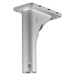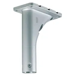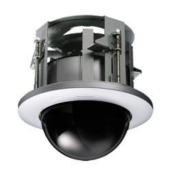
Preface
Mount the camera onto the ceiling or wall using this bracket.
Use this bracket when conduits are used for wiring, or when there is no space
available for wiring in the ceiling or wall.
For the latest information about the supported cameras, refer to our support website
(
https://i-pro.com/global/en/surveillance/training_support/support/technical_information
<Control No.:C0501>
).
Specifications
Ambient operating temperature: –50 °C to +60 °C {–58 °F to +140 °F}
Dimensions: ø127 mm × 56.5 mm (H) {ø5 inches × 2-7/32 inches(H)}
Mass: Approx. 470 g {1.04 lbs}
Finish: Aluminum die cast
i-PRO white <WV-QJB502-W>
Light gray <WV-QJB502-G>
Precautions for installation
■ In order to prevent injury, the product must be securely mounted to the wall or ceiling
according to the Installation Guide of the camera.
■ Make sure to remove this product if it will no longer be used.
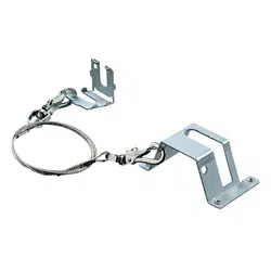
Standard accessories
Operating Instructions (this manual) .......... 1 pc.
The following parts are used during installation procedures.
Other items that are needed (not included)
• Fixing screw Recommended screw M4/4 or 2 pcs.
Minimum pull-out strength 196 N {44 lbf} (per 1 pc.)
Note:
• Select screws according to the material of the location that the camera will be mounted to.
In this case, wood screws and nails should not be used.
• For information about the minimum pull-out strength, refer to our support website
(https://i-pro.com/global/en/surveillance/training_support/support/technical_information
<Control No.: C0120>)
Attachment plate ......................................1 pc.
Fixing screw for camera
(M4×10 mm {13/32inches}) .................... 4 pcs.
(of them, 1 for spare)
Fixing screw for attachment plate
(M3×10 mm {13/32 inches}) ................... 5 pcs.
(of them, 1 for spare)
Cover ....................................................... 1 pc.
Ns1020-2042
© i-PRO Co., Ltd. 2022 Printed in China
Precautions
■ Do not use this bracket except with suitable cameras.
Failure to observe this may cause a drop resulting in injury or accidents.
■ Do not install this product on a place that is greatly infl uenced by wind.
Installation on a place where the wind speed is 60 m/s {approx. 134 mph} or more may cause
a fall of the product resulting in injury or accidents.
■ Refer installation work to the dealer.
Installation work requires technique and experience. Failure to observe this may cause fire,
electric shock, injury, or damage to the product. Be sure to consult the dealer.
■ Do not rub the edges of metal parts with your hand.
Failure to observe this may cause injury.
When using this product, also read the “Precautions” described in the operating instruc-
tions for the camera to be attached.
Operating Instructions
Included Installation Instructions
Base Bracket
Model No.
WV-QJB502-W
WV-QJB502-G
• Before attempting to connect or install this product, please read these instructions carefully and
save this manual for future use.
•T
he external appearance and other parts shown in this manual may differ from the actual
product within the scope that will not interfere with normal use due to improvement of the
product.
i-PRO Co., Ltd. assumes no responsibility for injuries or property damage resulting
from failures arising out of improper installation or operation inconsistent with this
documentation.
Preparations
[1] Remove the enclosure from the camera.
Refer to the Installation Guide of the corresponding camera for how to remove the enclosure
from the camera.
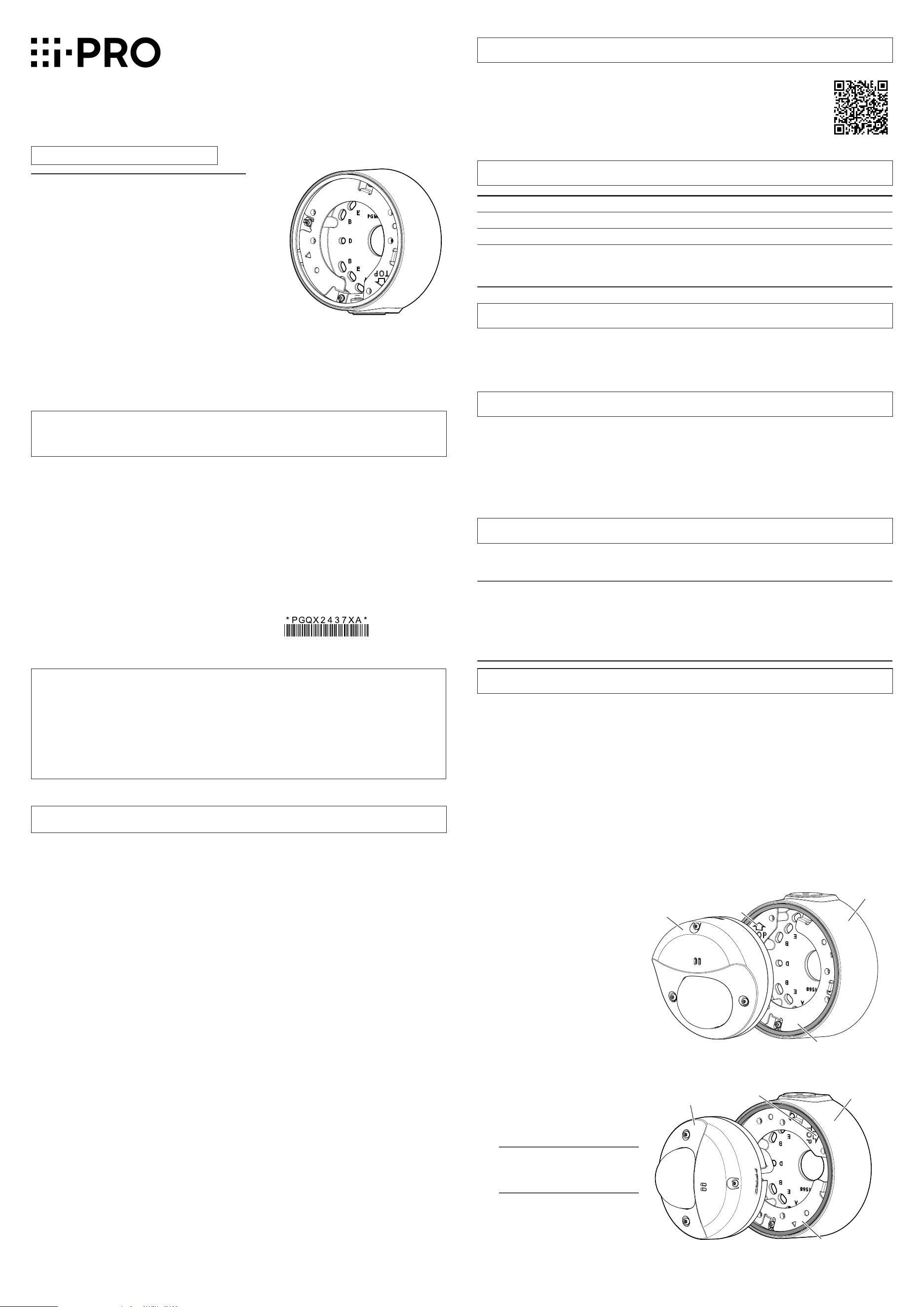
[2] Check the installation direction of the conduit and the image
capturing direction of the camera
Check the connection direction of the conduit (direction of the cable access hole for conduit
on this bracket) and the image capturing direction of the camera and then determine the
fixing position of the attachment plate. The fixing position of the attachment plate can be
changed with steps of 90°. The following is an example of the camera direction and the
fixing position of the attachment plate when connecting the conduit from the upper side.
<When the image capturing direction is downward>
Caution:
• Before attempting to connect or operate
this product, please read these instructions
carefully.
Notice:
• This product is not suitable for use in loca-
tions where children are likely to be present.
• Do not install this product in locations
where ordinary persons can easily reach.
• For information about screws and other
parts required for installation, refer to the
corresponding section of this document.
<When the image capturing direction is left side>
Camera
Base bracket
⇧TOP mark
Attachment plate
• Align the direction of the attach-
ment plate so that the “⇧TOP”
mark of the attachment plate
comes to the upper side.
• Align the direction of the attach-
ment plate so that the “⇧TOP”
mark of the attachment plate
comes to the right side.
Note:
• The connection cable is
omitted in the illustration.
Camera
⇧TOP mark
Attachment plate
Base bracket
For U.S. and Canada:
i-PRO Americas Inc.
For Europe and other countries:
i-PRO EMEA B.V.
https://www.i-pro.com/
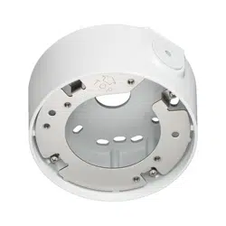
Parts and functions
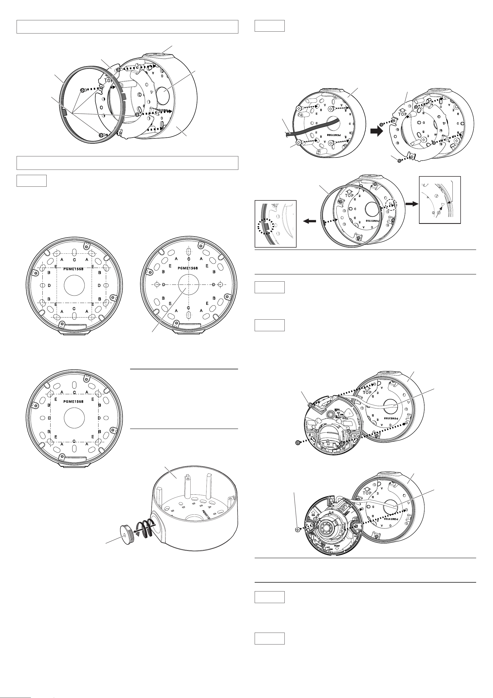
Installations
Step1
Make a hole on the installation surface.
[1] Make screw holes or anchor holes in the ceiling or wall, and also cable access hole if
necessary.
No cable access hole is needed when using conduit.
Attachment plate
(accessory)
Fixing screw for
attachment plate
(4pcs.)
(M3×10 mm {13/32
inches}: accessory)
Conduit wiring connector
Cable access hole
Base bracket
Note:
• When mounting to a single-gang junction
box, fix it with screws (2 pcs.) (M4: locally
procured).
• The direction of the attachment plate
(installation direction of the camera) can
be changed with steps of 90° even after
the base bracket is fixed.
83.5 mm × 46 mm
{3-9/32 inches × 1-13/16 inches}/
82.5 mm × 47.6 mm
{3-1/4 inches × 1-7/8 inches}
83.5 mm {3-9/32 inches}/
83.3 mm {3-9/32 inches}
63 mm {2-15/32 inches}/
63 mm {2-15/32 inches}
Cable access hole
ø25.4 mm {ø1 inch}
[2] Remove the cap for the female thread for the
conduit using a 5 mm {3/16 inches} hexagon
wrench and attach the conduit.
The female thread for conduit is compliant
with ANSI NPSM (parallel pipe threads) 3/4 or
ISO 228-1 (parallel pipe threads) G3/4.
Step2
Fix the base bracket and install the attachment plate and cover in
the direction described in [2] of “Preparations”.
[1] Install the base bracket on the installation surface.
Fixing screws (4 pcs.) (M4: locally procured)
Minimum pull-out strength: 196 N {44 lbf} (per 1 pc.)
[2] Install the attachment plate onto the base bracket and then attach the cover to the
attachment plate. The following is an example when this bracket is installed on the wall.
(Recommended tightening torque: 0.69 N·m {0.51 lbf·ft})
Base bracket
Cap for the female thread for
the conduit
Note:
• When installing this bracket outdoors, be sure to apply waterproofing to the cable access
hole and fixing screw holes.
A
Cable
Fixing screw (4 pcs.)
(M4: locally procured)
Fixing screw for
attachment plate
(4 pcs.)
(M3×10 mm {13/32
inches}: accessory)
Attachment plate
Base bracket
Step3
Connect the cables to the camera.
Connect an Ethernet cable to the RJ45 network cable from the camera.
Refer to the Installation Guide of the camera for how to install the waterproof connector.
Step4
Fix the camera body to this bracket.
(Recommended tightening torque: 1.37 N·m {1.01 lbf·ft})
<When the camera is a model to be fixed with three fixing screws for camera>
Cable
Fixing screw for camera (3 pcs.)
(M4×10 mm {13/32 inches}: accessory)
Cable
Base bracket
Base bracket
Fixing screw for camera (2 pcs.)
(M4×10 mm {13/32 inches}: accessory)
Note:
• When fixing the camera on this bracket, be careful not to pinch the cable with this bracket
and damage the cable sheath.
Step5
Adjust the angle of view of the camera.
Turn on the power of the camera and adjust the angular field of view of the camera.
Refer to the Installation Guide of the corresponding camera for how to connect to a network and
for how to adjust the angle of view of the camera.
Step6
Attach the enclosure.
After finishing the adjustment, attach the enclosure by following the instructions in the Installation
Guide of the corresponding camera.
Refer to the Installation Guide of the corresponding camera for the recommended tightening
torque to be applied when fixing the enclosure of the camera.
<When the camera is a model to be fixed with two fixing screws for camera>
Cover
(accessory)
Cover
(accessory)
△
Flat portion
Mark