VIVOTEK - A Leading Provider of Multimedia Communication Solutions
User's Manual - 1
Rev. 1.6.1.11
Rev. 1.0
User’s Manual
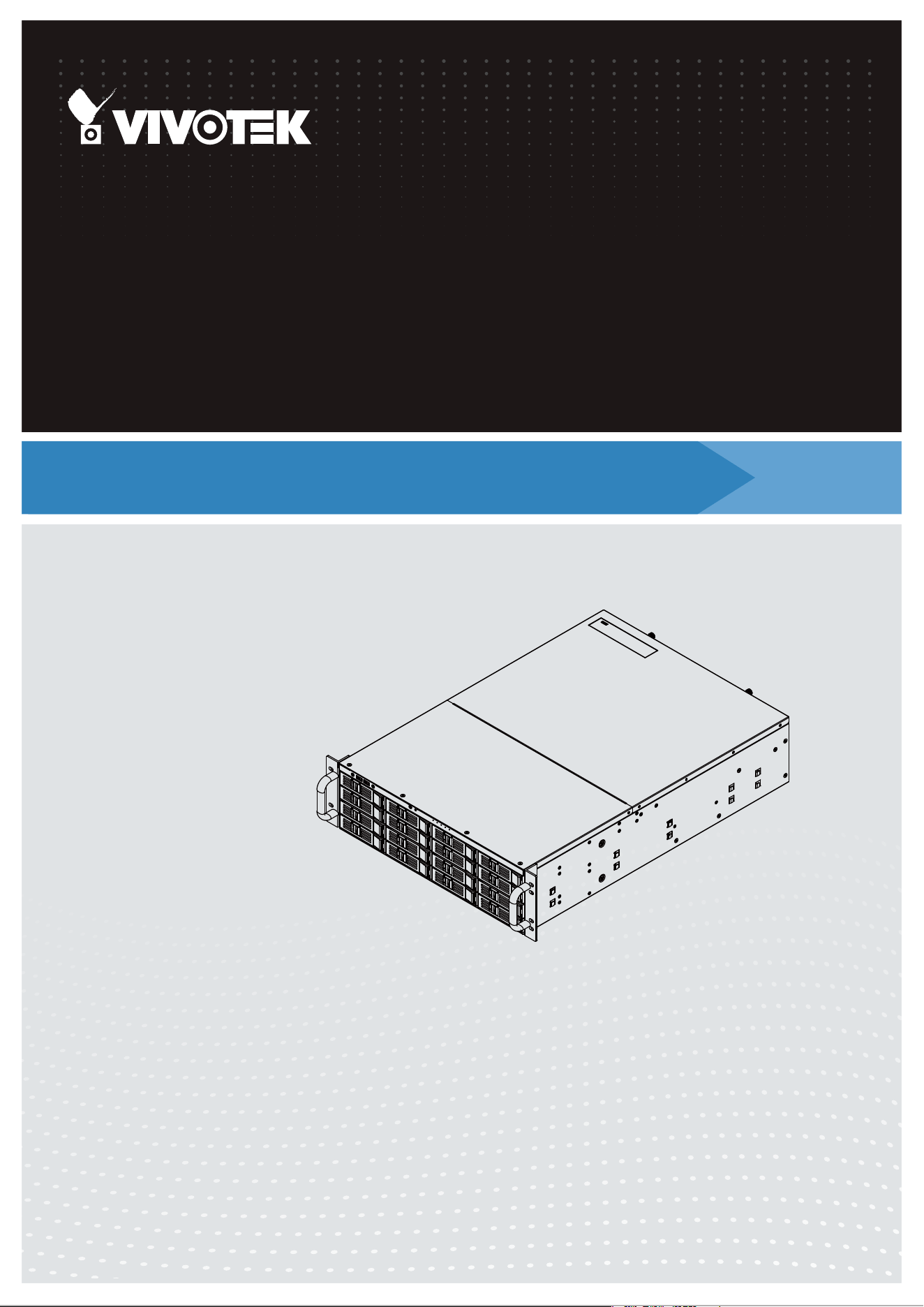
NR9782
Network Video Recorder
Rack-mount Enclosure • 64-/128-channel Recording • 96TB Max. Capacity
RAID storage • Full Integration with VIVOTEK Cameras
NR9682
Rev. 1.0
for VAST rev. 1.13

VIVOTEK - A Leading Provider of Multimedia Communication Solutions
2 - User's Manual
Table of Contents
Revision History ..................................................................................................................................................... 9
Chapter One Hardware Installation and Initial Conguration .................................................................................... 11
Introducing the NR9782 Network Video Recorder ............................................................................................... 11
Special Features ........................................................................................................................................... 11
Safety ............................................................................................................................................................ 12
Installation Instructions ........................................................................................................................................ 13
Power Supply ................................................................................................................................................ 14
Environmental Specications ........................................................................................................................ 14
Physical Description ........................................................................................................................................... 15
Drive Bay Numbering Sequence .......................................................................................................................... 15
Front View ............................................................................................................................................................ 15
Rear View ............................................................................................................................................................. 17
Display .......................................................................................................................................................... 18
Chassis Dimensions ...................................................................................................................................... 19
Rack-mounting ..................................................................................................................................................... 20
Installing Hard Disk Drives ................................................................................................................................... 24
Connecting Interfaces .......................................................................................................................................... 26
Initial Conguration ............................................................................................................................................... 26
RAID Basics ......................................................................................................................................................... 45
Technical Specications ....................................................................................................................................... 62
VAST Server and Client Components .................................................................................................................. 63
Usage Scenario .................................................................................................................................................... 63
Technical Specications ....................................................................................................................................... 64
VAST Server Functionality .................................................................................................................................... 66
VAST LiveClient Functionality .............................................................................................................................. 67
VAST Playback Functionality ................................................................................................................................ 68
Minimum System Requirements .......................................................................................................................... 69
VAST Software License ........................................................................................................................................ 71
Reminders for VAST Software License ................................................................................................................ 72
VAST Installation ....................................................................................................................................................... 74
Installing the VAST Software (This is in case you need to re-install the software) .............................................. 74
VAST Server .............................................................................................................................................................. 78
Activating the VAST Server .................................................................................................................................. 78
How to Congure the Server ................................................................................................................................ 78
How to Stop/Reboot the Server ............................................................................................................................ 78
VAST LiveClient Conguration .................................................................................................................................. 79
Activating the VAST LiveClient and Logging in to a VAST Server ........................................................................ 79
VAST LiveClient User Interface ............................................................................................................................ 81
Menu Bar ....................................................................................................................................................... 81
Status Panel .................................................................................................................................................. 82
Help Panel ............................................................................................................................................................ 83
Quick Access Bar .......................................................................................................................................... 84

VIVOTEK - A Leading Provider of Multimedia Communication Solutions
User's Manual - 3
Live Video Monitoring Window ...................................................................................................................... 84
Hierarchical Management Tree ..................................................................................................................... 85
Camera Control Panel ................................................................................................................................... 86
Pan/Tilt/Zoom (PTZ) Control Panel ........................................................................................................ 86
Two Way Audio Control Panel ................................................................................................................ 88
Language Selection ............................................................................................................................... 88
Alarm Window ............................................................................................................................................... 89
Alarm Filter ............................................................................................................................................. 90
Alarm State ............................................................................................................................................ 91
Instant Playback ............................................................................................................................................ 92
Instant Replay ............................................................................................................................................... 93
Audio Control ................................................................................................................................................ 94
How to Manage Devices ...................................................................................................................................... 95
Insert Cameras .............................................................................................................................................. 95
Seamless Recording ..................................................................................................................................... 99
Enable SVC ................................................................................................................................................ 102
Streaming URL ............................................................................................................................................ 105
Insert NVR (Network Video Recorder) ........................................................................................................ 106
Insert a Video Server ................................................................................................................................... 109
Update Devices ............................................................................................................................................111
Delete Devices from the VAST Server ........................................................................................................ 112
Batch Insert Devices ................................................................................................................................... 113
Camera Conguration ................................................................................................................................. 11 8
View Live Videos ......................................................................................................................................... 123
Dual / Multiple Streams ........................................................................................................................ 123
Fisheye Display Modes ........................................................................................................................ 123
Refresh ................................................................................................................................................. 128
Streaming Server ................................................................................................................................. 128
Output Camera List ............................................................................................................................. 128
Get Public IP ........................................................................................................................................ 128
Camera Settings .................................................................................................................................. 129
Remove Live Video from the Video Monitoring Window ............................................................................. 130
How to Change the VAST LiveClient Layout ...................................................................................................... 131
Changing the Layout of the Live Video Monitoring Window ........................................................................ 131
Switch Video Channels ........................................................................................................................ 131
Congure Layout Mode ........................................................................................................................ 132
Congure Layout Mode ........................................................................................................................ 132
Rotating Video Pages .......................................................................................................................... 134
Edit Layout ........................................................................................................................................... 134
Scheduled Layout Rotation .................................................................................................................. 136
Maximize/Minimize the Live Video Monitoring Window ............................................................................... 140
View Live Video on Dual Monitors ............................................................................................................... 141
Simultaneously Viewing up to 128 Channels ....................................................................................... 142
Using different layouts on each monitor ............................................................................................... 142
View Live Video with Multiple Monitors ....................................................................................................... 143
How to Manage Stations .................................................................................................................................... 144
Relay Settings ............................................................................................................................................. 144

VIVOTEK - A Leading Provider of Multimedia Communication Solutions
4 - User's Manual
Insert Sub-stations ...................................................................................................................................... 145
Delete Sub-stations ..................................................................................................................................... 148
Update Stations ........................................................................................................................................... 149
How to Manage User Accounts .......................................................................................................................... 150
The Default User Roles and Permissions of User Accounts ....................................................................... 150
Manage a User Account .............................................................................................................................. 152
Add a New User Account - Basic Account ........................................................................................... 152
Add a New User Account - Windows AD Account ................................................................................ 153
Permission of the User Account .................................................................................................................. 156
Delete the User Account ............................................................................................................................. 157
How to Set up Association Management ............................................................................................................ 159
Association Management ............................................................................................................................ 159
How to Set up Alarm Management ..................................................................................................................... 161
Alarm Management ..................................................................................................................................... 161
How to Manage the Virtual Matrix ...................................................................................................................... 172
The architecture of VAST Matrix ................................................................................................................. 172
Installing VAST Matrix Program .................................................................................................................. 173
Launching VAST Matrix ............................................................................................................................... 174
Conguration ........................................................................................................................................ 175
View Settings ....................................................................................................................................... 175
About .................................................................................................................................................... 175
Exit ....................................................................................................................................................... 175
VAST Matrix Management .......................................................................................................................... 176
Matrix Management Settings ............................................................................................................... 176
Manage VAST Matrix through VAST LiveClient ................................................................................... 178
Matrix View Settings .................................................................................................................................... 179
Search VIVOCam Switches ............................................................................................................................... 182
How to Congure the Station General Settings .................................................................................................. 183
Server Settings ............................................................................................................................................ 183
Log Settings ................................................................................................................................................ 183
How to Congure Station Network Settings ....................................................................................................... 184
Port Settings ................................................................................................................................................ 184
UPnP Settings ............................................................................................................................................. 184
Proxy Settings ............................................................................................................................................. 184
Web Access Settings ................................................................................................................................... 184
How to Edit Recording Groups ........................................................................................................................... 185
Recording Storage Settings ........................................................................................................................ 185
Default Storage Group Settings ........................................................................................................... 186
Add New Recording Group(s) .............................................................................................................. 188
Multiple Stream Recording ................................................................................................................... 189
How to Edit Recording Schedules ...................................................................................................................... 191
Edit Schedule List ....................................................................................................................................... 192
Add Schedules ..................................................................................................................................... 192
Rename Schedules .............................................................................................................................. 192
Delete Schedules ................................................................................................................................. 192
Load/Save Schedule Templates ........................................................................................................... 193
Edit Camera List .......................................................................................................................................... 194
Edit Time Frame List ................................................................................................................................... 195

VIVOTEK - A Leading Provider of Multimedia Communication Solutions
User's Manual - 5
Add New Time Frames ......................................................................................................................... 196
Recording Settings ............................................................................................................................... 197
The Concept of Repeat Frequency ............................................................................................................. 199
Repeat Frequency: Daily Setting ......................................................................................................... 200
Repeat Frequency: Weekly Setting (Day-based) ................................................................................. 203
Repeat Frequency: Monthly Setting (Day-based) ................................................................................ 206
Repeat Frequency: Yearly Setting (Day-based) ................................................................................... 208
How to Manually Begin /Stop Recording ............................................................................................................ 210
How to Edit Scheduled Backup Settings ............................................................................................................ 211
Select Backup Source ................................................................................................................................. 211
Setup Backup Schedule .............................................................................................................................. 212
Select Backup Target .................................................................................................................................. 212
How to Congure Station Server Settings .......................................................................................................... 213
DDNS Settings ............................................................................................................................................ 213
Network Storage Server Settings ................................................................................................................ 214
SMTP Settings ............................................................................................................................................ 215
How to Use the Talk Panel ................................................................................................................................. 216
Add a Camera to the Talk Panel .................................................................................................................. 216
Remove a Camera from the Talk Panel ...................................................................................................... 218
How to Congure E-map Settings ...................................................................................................................... 219
Upload an E-map ........................................................................................................................................ 219
User Interface of E-map Settings Page (View Mode) .................................................................................. 220
Quick Access Bar ................................................................................................................................. 221
Status Panel ......................................................................................................................................... 221
User Interface of E-map Settings Page (Edit Mode) ................................................................................... 222
Device Management ................................................................................................................................... 223
Live View Dialog Settings ............................................................................................................................ 224
Open Live View Dialog ......................................................................................................................... 224
Send to Single View ............................................................................................................................. 224
E-map Link .................................................................................................................................................. 225
How to Congure Client Settings ....................................................................................................................... 229
Snapshot Settings ....................................................................................................................................... 229
Take a Snapshot .................................................................................................................................. 230
Recording Settings ...................................................................................................................................... 231
Type 1: Record to EXE ........................................................................................................................ 231
Type 2: Record to 3GP ......................................................................................................................... 231
Type 3: Record to AVI .......................................................................................................................... 232
Built-in Media Player--EXE ................................................................................................................... 235
View Settings ............................................................................................................................................... 237
Display Location ................................................................................................................................... 237
Date and Time Format ......................................................................................................................... 238
Video Display Mode ............................................................................................................................. 238
Font Settings ........................................................................................................................................ 239
General Settings ......................................................................................................................................... 240
System Settings ................................................................................................................................... 240
Alarm Settings ...................................................................................................................................... 241
Rotation Settings .................................................................................................................................. 242
Display Settings ................................................................................................................................... 243

VIVOTEK - A Leading Provider of Multimedia Communication Solutions
6 - User's Manual
Joystick Settings ......................................................................................................................................... 245
Enable Joystick .................................................................................................................................... 245
Joystick Settings - Using VIVOTEK's AJ-001 & AJ-002 .............................................................................. 251
Proxy Settings ............................................................................................................................................. 255
How to Use PiP (Picture-in-Picture) ................................................................................................................... 256
Enable PiP ................................................................................................................................................... 256
Global View .......................................................................................................................................... 256
ROI (Region of Interest) ....................................................................................................................... 257
Digital Zoom In ..................................................................................................................................... 257
Snapshot & Print Zoomed In Image ..................................................................................................... 257
PiP Settings .......................................................................................................................................... 257
Multi-touch Mode .................................................................................................................................. 258
How to Congure Video Enhancement .............................................................................................................. 259
Basic Image Adjustment .............................................................................................................................. 259
Defog ........................................................................................................................................................... 261
Apply a Preset Defog Prole ................................................................................................................ 261
Create a New Defog Prole ................................................................................................................. 262
How to Search for a Device on the Hierarchical Management Tree .................................................................. 264
How to Print a Video Image ................................................................................................................................ 265
How to Lock LiveClient for Security Concerns ................................................................................................... 265
How to Log out from the VAST Server ............................................................................................................... 266
How to Exit VAST LiveClient .............................................................................................................................. 266
How to Congure a Logical Tree ........................................................................................................................ 267
VAST Playback Conguration ................................................................................................................................. 274
Activating VAST Playback and Logging in to a Server ....................................................................................... 274
VAST Playback User Interface ........................................................................................................................... 275
Menu Bar ..................................................................................................................................................... 275
Status Panel ................................................................................................................................................ 275
Quick Access Bar ........................................................................................................................................ 276
Recorded Video Playback Window ............................................................................................................. 276
Language Selection .................................................................................................................................... 277
Query Panel-- Browsing Page ..................................................................................................................... 277
Query Panel--Time Search Page ................................................................................................................ 279
Query Panel--Event Search Page ............................................................................................................... 280
Query Panel--Bookmark Search Page ........................................................................................................ 281
Query Panel--Alarm Search Page ............................................................................................................... 282
Query Panel--Log Viewer Page ................................................................................................................... 283
Video Clips List Window .............................................................................................................................. 284
Playback Control Panel ............................................................................................................................... 285
Rewind ........................................................................................................................................................ 286
How to Playback Recorded Video ...................................................................................................................... 287
Select a Recorded Video Clip ..................................................................................................................... 287
Remove Recorded Video Clips from Video Cells ........................................................................................ 290
Timeline Slider Bar and Histogram .............................................................................................................. 290
Zoom in / out of the Histogram .................................................................................................................... 291
Synchronous Playback ................................................................................................................................ 292
Audio Control .............................................................................................................................................. 294
How to Change the Playback Layout ................................................................................................................. 295

VIVOTEK - A Leading Provider of Multimedia Communication Solutions
User's Manual - 7
Changing the Layout of the Recorded Video Playback Window ................................................................. 295
Switch Video Channels ........................................................................................................................ 295
Congure Layout Mode ........................................................................................................................ 295
Maximize/Minimize the Recorded Video Playback Window ........................................................................ 296
View Recorded Video with Multiple Monitors .............................................................................................. 297
How to Backup Recorded Video ........................................................................................................................ 298
How to Search for a Video Clip in a Specic Period of time ............................................................................... 304
How to Add a Bookmark ..................................................................................................................................... 305
How to Search for Events ................................................................................................................................... 306
Select Event Category ................................................................................................................................ 307
Event Category- All Events .................................................................................................................. 307
Event Category- All Motion Events....................................................................................................... 307
Event Category- All IVA events ............................................................................................................ 308
Event Category- All DI Events .............................................................................................................. 308
Event Category- Named DI Events ...................................................................................................... 309
Start Event Search ...................................................................................................................................... 310
Backup the Event Videos ............................................................................................................................ 3 11
How to Search for a Bookmark .......................................................................................................................... 312
How to Search Logs ........................................................................................................................................... 313
Select Log Category/Log Type/Log Level ................................................................................................... 314
Search All Local Logs........................................................................................................................... 315
Search Login History ............................................................................................................................ 315
Search Login Activities ......................................................................................................................... 316
How to Congure Client Settings ....................................................................................................................... 318
Snapshot Settings ....................................................................................................................................... 318
Export Settings ............................................................................................................................................ 318
View Settings ............................................................................................................................................... 320
Proxy Settings ............................................................................................................................................. 320
General Settings ......................................................................................................................................... 320
System Settings ................................................................................................................................... 320
Display Settings ................................................................................................................................... 320
How to Congure Video Enhancement .............................................................................................................. 320
How to Search for a Device on the Hierarchical Management Tree .................................................................. 320
How to Print a Video Image ................................................................................................................................ 320
How to Lock VAST Playback for Security Concerns .......................................................................................... 321
How to Log out from the VAST Server ............................................................................................................... 321
How to Exit VAST Playback ................................................................................................................................ 321
Import and Export Utility .......................................................................................................................................... 322
Export Utility ....................................................................................................................................................... 322
Import Utility ....................................................................................................................................................... 322
VAST Service Control Tool ...................................................................................................................................... 324
Appendix A Failover Server Conguration ............................................................................................................... 325
Failover Conguration Process .......................................................................................................................... 333
Appendix B Panoramic PTZ (P-PTZ) Conguration ................................................................................................ 338
Enable Panoramic PTZ on VAST ...................................................................................................................... 338
Panoramic PTZ - Event Trigger ......................................................................................................................... 341

VIVOTEK - A Leading Provider of Multimedia Communication Solutions
8 - User's Manual
Enable or Disable the Panoramic PTZ Functions ............................................................................................. 343
Appendix C ONVIF Support .................................................................................................................................... 344
Appendix D VCA Report .......................................................................................................................................... 346
Appendix E Support for Digital I/O Modbus TCP Modules ...................................................................................... 357
Appendix F Database Merge Function .................................................................................................................... 362
Appendix G Other Parameters ................................................................................................................................ 368
VIVOTEK - A Leading Provider of Multimedia Communication Solutions
User's Manual - 9
Revision History
Rev. 1.0: Initial release. The description for the software functionality is based on VAST rev.
1.13.1.10.
1. No storage system is completely fail-safe. Damage to data might occur due to le system
corruption, operating system malfunction, virus infection, HDD component failures, and so on.
Therefore, it is highly recommended to regularly back up your data, and VIVOTEK disclaims
responsibilities of data loss or recovery.
2. Always power off the system using the power down button on system desktop. Do not
disconnect the power cord while the system is still operating. Doing so will result in data
inconsistencies. The normal power-off procedure allows cached data to be written to disks.
WARNING:
Technology License Notice
Notices from HEVC Advance:
THIS PRODUCT IS SOLD WITH A LIMITED LICENSE AND IS AUTHORIZED TO BE USED ONLY
IN CONNECTION WITH HEVC CONTENT THAT MEETS EACH OF THE THREE FOLLOWING
QUALIFICATIONS: (1) HEVC CONTENT ONLY FOR PERSONAL USE; (2) HEVC CONTENT THAT
IS NOT OFFERED FOR SALE; AND (3) HEVC CONTENT THAT IS CREATED BY THE OWNER OF
THE PRODUCT. THIS PRODUCT MAY NOT BE USED IN CONNECTION WITH HEVC ENCODED
CONTENT CREATED BY A THIRD PARTY, WHICH THE USER HAS ORDERED OR PURCHASED
FROM A THIRD PARTY, UNLESS THE USER IS SEPARATELY GRANTED RIGHTS TO USE THE
PRODUCT WITH SUCH CONTENT BY A LICENSED SELLER OF THE CONTENT. YOUR USE OF
THIS PRODUCT IN CONNECTION WITH HEVC ENCODED CONTENT IS DEEMED ACCEPTANCE
OF THE LIMITED AUTHORITY TO USE AS NOTED ABOVE.
VIVOTEK - A Leading Provider of Multimedia Communication Solutions
10 - User's Manual
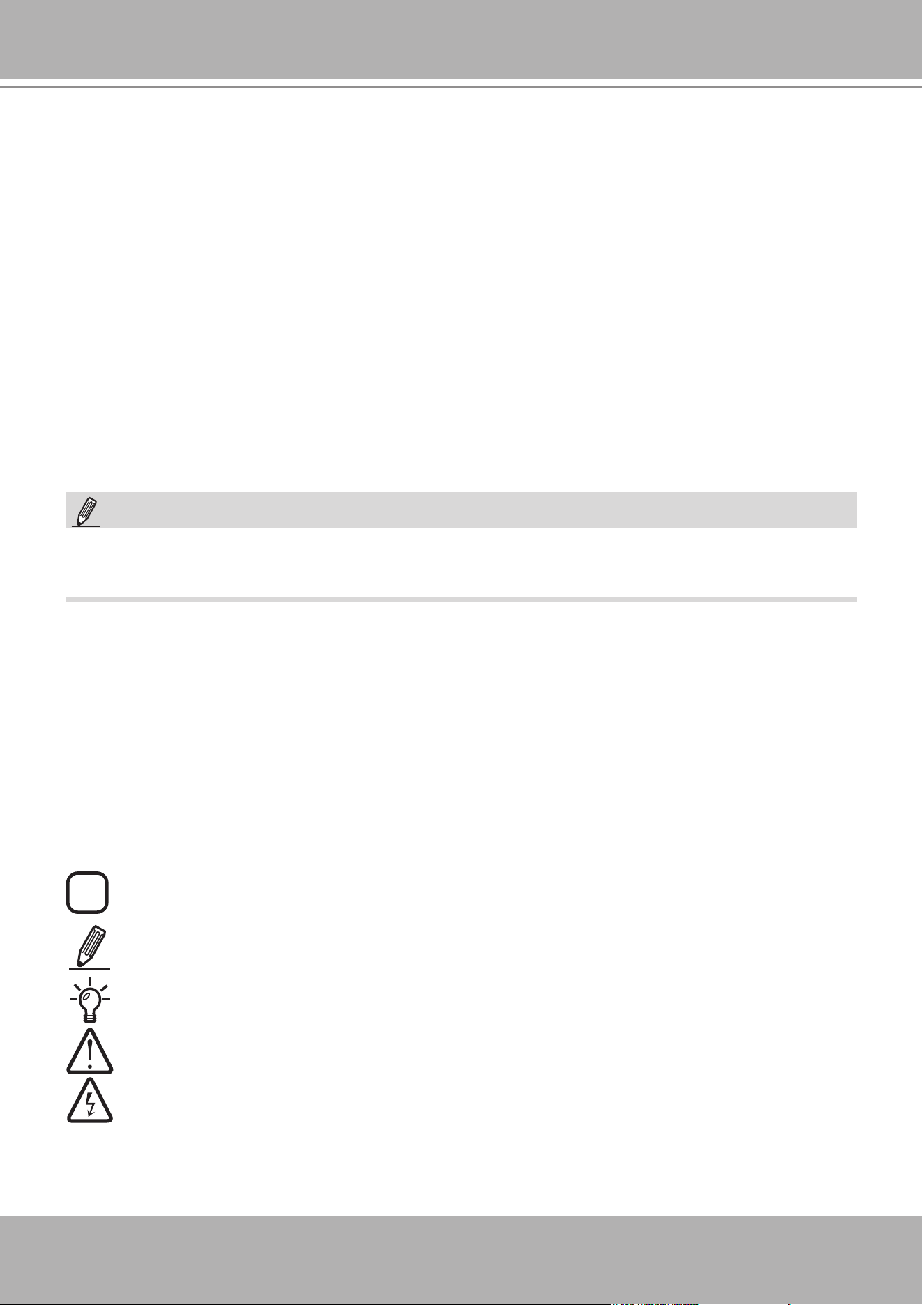
Symbols and Statements in this Document
i
INFORMATION:
provides important messages or advices that might help prevent inconvenient
or problem situations.
NOTE
: Notices provide guidance or advices that are related to the functional integrity of the
machine.
Tips
: Tips are useful information that helps enhance or facilitae an installation, function, or
process.
WARNING!
or
IMPORTANT
: These statements indicate situations that can be dangerous or
hazardous to the machine or you.
Electrical Hazard
: This statement appears when high voltage electrical hazards might occur
to an operator.
Read Before Use
The use of surveillance devices may be prohibited by law in your country. The Network Camera
is not only a high-performance web-ready camera but can also be part of a exible surveillance
system. It is the user’s responsibility to ensure that the operation of such devices is legal before
installing this unit for its intended use.
It is important to first verify that all contents received are complete according to the Package
Contents listed below. Take note of the warnings in the Quick Installation Guide before the
Network Camera is installed; then carefully read and follow the instructions in the Installation
chapter to avoid damage due to faulty assembly and installation. This also ensures the product is
used properly as intended.
The Network Camera is a network device and its use should be straightforward for those who
have basic networking knowledge. It is designed for various applications including video sharing,
general security/surveillance, etc. The Configuration chapter suggests ways to best utilize the
Network Camera and ensure proper operations. For creative and professional developers, the
URL Commands of the Network Camera section serves as a helpful reference to customizing
existing homepages or integrating with the current web server.
Package Contents
■ NR9682 or NR9782
■ Power cords
■ Software CD
■ Warranty Card
■ Mouse
■ Quick Installation Guide
■ Screws and slide rails
The operating system and management software are installed on a ash memory mounted on
the main board. Except for the plug-ins for onscreen display, there is no need to install software.
NOTE:

VIVOTEK - A Leading Provider of Multimedia Communication Solutions
User's Manual - 11
Chapter One Hardware Installation and Initial
Conguration
Introduction
NR9682/NR9782 is the latest 64-/128-channel H.265, RAID-protected NVR from VIVOTEK,
bringing stable and efficient system operation under a wide range of recording/network man-
agement/system settings. The unit supports all VIVOTEK camera models, including the latest
5-Megapixel and fisheye cameras. The support for RAID 1/5/6/10 provides data security in the
event of disk drive failure.
The unit is equipped with two gigabit Ethernet RJ45 ports which provide network failover func-
tionality to avoid the risk of recording loss. When one network line is disconnected, the system
will shift to the other network automatically, providing continuous access for video data. Up to
16 HDDs can be installed in the NR9782 for a total storage capacity of up to 96TB (6TB max.
each). The hot-swappable HDD trays are available in the front of the unit, with hot-swap func-
tionality for easy replacement.
A VAST CMS server runs on the machine that manages surveillance recording and playback.
The compatibility with the iViewer application allows for remote access to the NR9682/NR9782
on handheld devices. By integrating all of the components together using VIVOTEK’s NR9682/
NR9782, network cameras, VAST, and iViewer software, users can realize a fully-featured and
robust next-generation surveillance system. This ingenious NVR also features the remote man-
agement capability with a full range of server/client structures and thus is capable for robust and
diverse applications.
Special Features
● Runs on embedded Windows
● 3U Rack Mount Design
● RAID 0, 1, 5, 6, 10, 50, 60 in virtual drive storage configurations
● 16 x HDD Tray, for a max. capacity of 96TB
● 2 x Gigabit RJ45 Ethernet ports
● 8 (QG2,WG2: 6 x USB 3.0, 2 x USB 2.0; L: 4 x USB3.0, 4 x USB2.0)
● Size: (W x H x D) 435 x 132 x 540 mm (17.13” x 5.2” x 21.26”)
● 128-CH Live View & 16-CH Synchronous Playback
● H.265/H.264/ MPEG-4
● PTZ Support
● Snapshot / Export Media
● PiP Video Control
● Bookmark Design
● Fast Configuration Backup / Restore
● Pre-installed VIVOTEK VAST Central Management Software*
● Full Integration with VIVOTEK Network Cameras
● VIVOTEK iViewer Support (iOS/Android)

VIVOTEK - A Leading Provider of Multimedia Communication Solutions
12 - User's Manual
Safety
1. Read these safety instructions carefully.
2. Keep this User Manual for later reference.
3. Disconnect this equipment from any AC outlet before cleaning. Use a damp cloth. Do not use
liquid or spray detergents for cleaning.
4. For plug-in equipment, the power outlet socket must be located near the equip-ment and
must be easily accessible.
5. Keep this equipment away from humidity.
6. Put this equipment on a reliable surface during installation. Dropping it or letting it fall may
cause damage.
7. For rack-mount equipment, please firmly install the device with pallets or sliding rails in the
rack.
8. Do not leave this equipment in an environment unconditioned where the storage temperature
under 0° C (32° F) or above 40° C (104° F), it may damage the equipment.
9. The openings on the enclosure are for air convection. Protect the equipment from overheat-
ing. DO NOT COVER THE OPENINGS.
10. Make sure the voltage of the power source is correct before connecting the equipment to the
power outlet.
11. Position the power cord so that people cannot step on it. Do not place anything over the
power cord.
12. All cautions and warnings on the equipment should be noted.
13. If the equipment is not used for a long time, disconnect it from the power source to avoid
damage by transient overvoltage.
14. Never pour any liquid into an opening. This may cause fire or electrical shock.
15. Never open the equipment. For safety reasons, the equipment should be opened only by
qualified service personnel.
16. If one of the following situations arises, get the equipment checked by service personnel:
The power cord or plug is damaged.
Liquid has penetrated into the equipment.
The equipment has been exposed to moisture.
The equipment does not work well, or you cannot get it to work according to the user's
manual.
The equipment has been dropped and damaged.
The equipment has obvious signs of breakage.
17.
CAUTION
: The computer is provided with a battery-powered real-time clock cir-cuit. There is
a danger of explosion if battery is incorrectly replaced. Replace only with same or equivalent
type recommended by the manufacture. Discard used batteries according to the manufac-
turer’s instructions.
18. This device complies with Part 15 of the FCC rules. Operation is subject to the following
two conditions: (1) this device may not cause harmful interference, and (2) this device must
accept any interference received, including interferencethat may cause undesired operation.
VIVOTEK - A Leading Provider of Multimedia Communication Solutions
User's Manual - 13
Installation Instructions
Warning:
Read the installation instructions before connecting the system to the power source.
Warning:
This product relies on the building’s installation for short-circuit (overcurrent) protection.
Ensure that the protective device is rated not greater than: 250V, 20 A.
Warning:
The system must be disconnected from all sources of power and the power cord.re-
moved from the power supply module(s) before accessing the chassis interior to install or
remove system components.
Warning:
Only trained and qualifiedpersonnel should be allowed to install, replace, or service this
equipment.
Warning:
This unit is intended for installation in restricted access areas. A restricted access area
can be accessed only through the use of a special tool, lock and key, or other means of
security. (This warning does not apply to workstations).
Warning:
There is the danger of explosion if the battery is replaced incorrectly. Replace the bat-
tery only with the same or equivalent type recommended by the manufacturer. Dispose of
used batteries according to the manufacturer’s instructions.
Warning:
This unit might have more than one power supply connection. All connections must be re-
moved to de-energize the unit.
19.
CAUTION
: Always completely disconnect the power cord from your chassis whenever you
work with the hardware. Do not make connections while the power is on. Sensitive electronic
components can be damaged by sudden power surges.
20.
CAUTION
: Always ground yourself to remove any static charge before touching the
motherboard, backplane, or add-on cards. Modern electronic devices are very sensitive to
static electric charges. As a safety precaution, use a grounding wrist strap at all times. Place
all electronic components on a static-dissipative surface or in a static-shielded bag when
they are not in the chassis.
21.
CAUTION
: Any unveried component could cause unexpected damage. To ensure the
correct installation, please always use the components (e.g., screws) provided with the
accessory box.
VIVOTEK - A Leading Provider of Multimedia Communication Solutions
14 - User's Manual
Warning:
Hazardous voltage or energy is present on the backplane when the system is operating.
Use caution when servicing.
Warning:
Installation of the equipment must comply with local and national electrical codes.
Warning:
Ultimate disposal of this product should be handled according to all national laws and
regulations.
Warning:
The fans might still be turning when you remove the fan assembly from the chassis. Keep
fingers,screwdrivers, and other objects away from the openings in the fan assembly’s
housing.
Warning:
When installing the product, use the provided or designated connection cables, power
cables and AC adaptors. Using any other cables and adaptors could cause a malfunction
or a fire.Electrical Appliance and Material Safety Law prohibits the use of UL or CSA -cer-
tified cables (that have UL/CSA shown on the code) for any other electrical devices than
products designated by the manufacturer only.
Power Supply
Watt 550W max. (80+ Gold, PFC) (1+1 Redundant 2U)
Input rating 100 ~ 240 Vac ~6.9A-2.8A, 50-60Hz
Output voltage +5 VSB @ 2.5 A, +12 V @ 45A
Minimum load +12V @ 0.5 A
Safety UL/TUV/CCC
Environmental Specications
Environment Operating Non-operating
Temperature
0 ~ 40°C (32 ~ 104°F) --40 ~ 70°C (-40 ~ 158°F)
Humidity 10 ~ 95% @ 40°C, non-condensing 10 ~ 95% @ 60°C, non-condensing
Vibration 0.5 G rms 2 G
Shock 10 G with 11 ms duration, half sine wave
Safety CE compliant
VIVOTEK - A Leading Provider of Multimedia Communication Solutions
User's Manual - 15
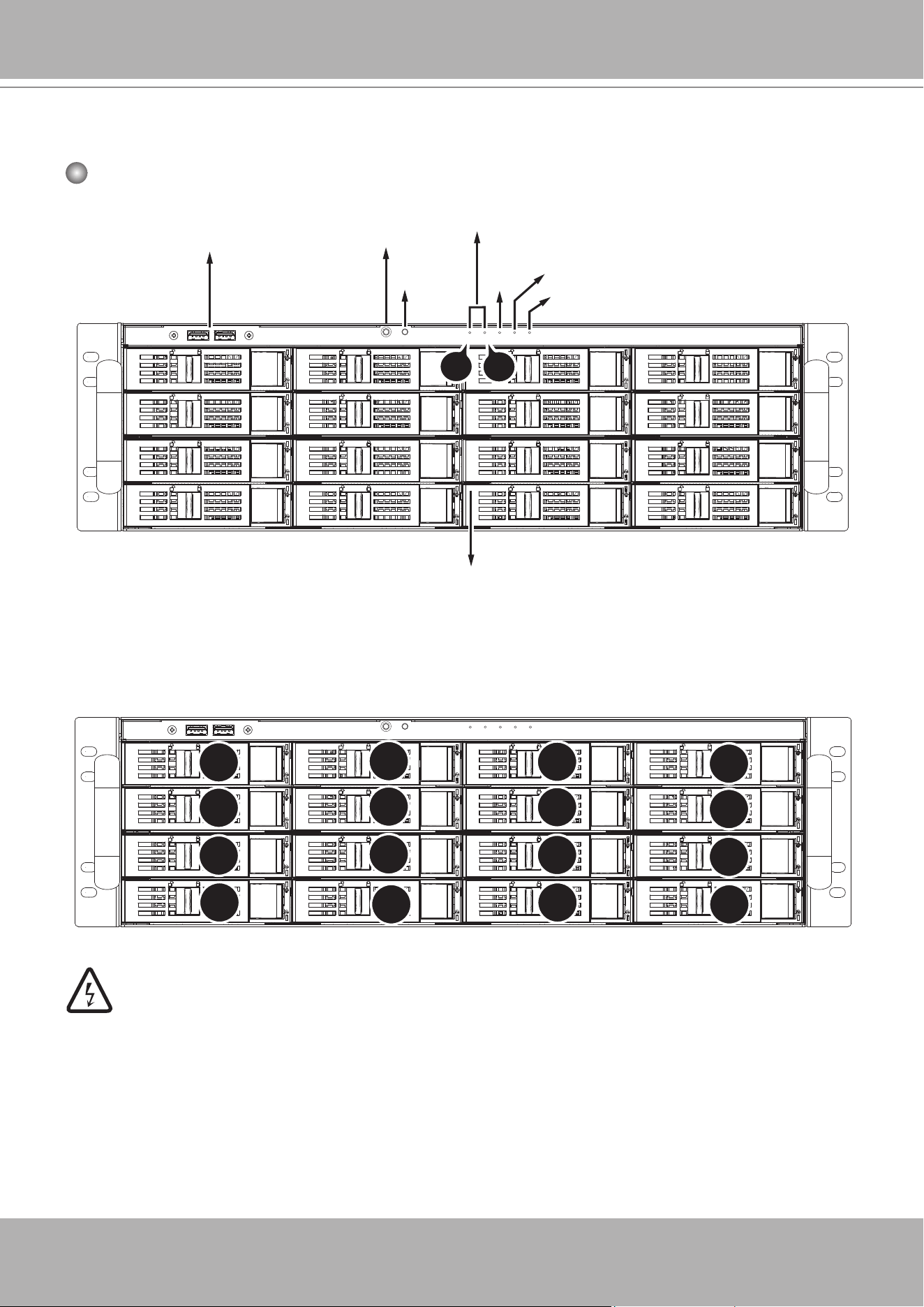
Physical Description
Front View
Power switch
Reset
button
USB 3.0
LAN LED
Power LED
HDD
LED
Information LED
Hot-swappable 2.5”/3.5” HDD trays
2
1
0
1
2
3
4
5
6
7
8
9
10
11
12
13
14
15
Drive Bay Numbering Sequence
Warning:
Knowing the correction positions of hard drives is very important. For example, if a hard
drive fails in a RAID5 Virtual Drive, you can initialize a rebuild by locating and replacing
the failed drive. If you replace the wrong drive, it means that you have 1 failed drive and
another mistakenly failed drive. Having 2 failed drives in a RAID5 configuration renders
all data inaccessible. All data in the RAID5 Virtual Drive will be lost.
VIVOTEK - A Leading Provider of Multimedia Communication Solutions
16 - User's Manual
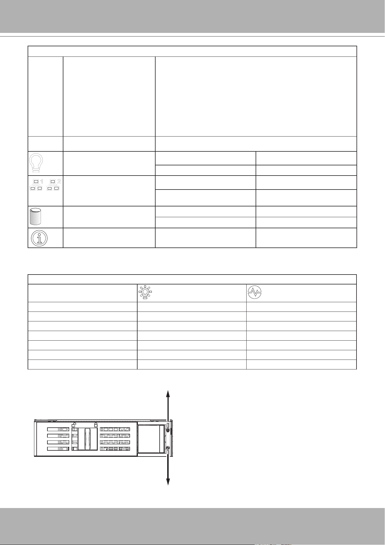
Control Panel buttons and LEDs
Power switch Press this switch to turn the system power on or off. Please use
system shutdown or press this switch for few seconds to turn
off the system ATX power.
The main power switch is used to apply or remove power from
the power supplies to the server. Turning off system power
using this button removes the main power but keeps standby
power supplied to the system. You must unplug the system
before servicing components inside the chassis.
Reset button Press this button to reboot the system.
Power LED Blue Red
ON: Normal N/A
LAN status LED ON: Normal N/A
Blinking: transmitting data. N/A
HDD LED* Blinking: data access. N/A
OFF: idle N/A
Information: PEF occurred
by motherboard's BMC
N/A ON: System abnormal.
* The HDD LED here only displays the status for those attached to the motherboard.
Activity
Status
Front Hot-swappable Drive Tray LEDs
Activity LED: Green
Status LED: Amber
Drive not present OFF OFF
Drive present, no activity
ON OFF
Drive present, activity 4Hz
blinking OFF
Locate (Identify) OFF 4Hz
blinking
Fail OFF ON
Rebuild OFFF 1Hz blinking
VIVOTEK - A Leading Provider of Multimedia Communication Solutions
User's Manual - 17
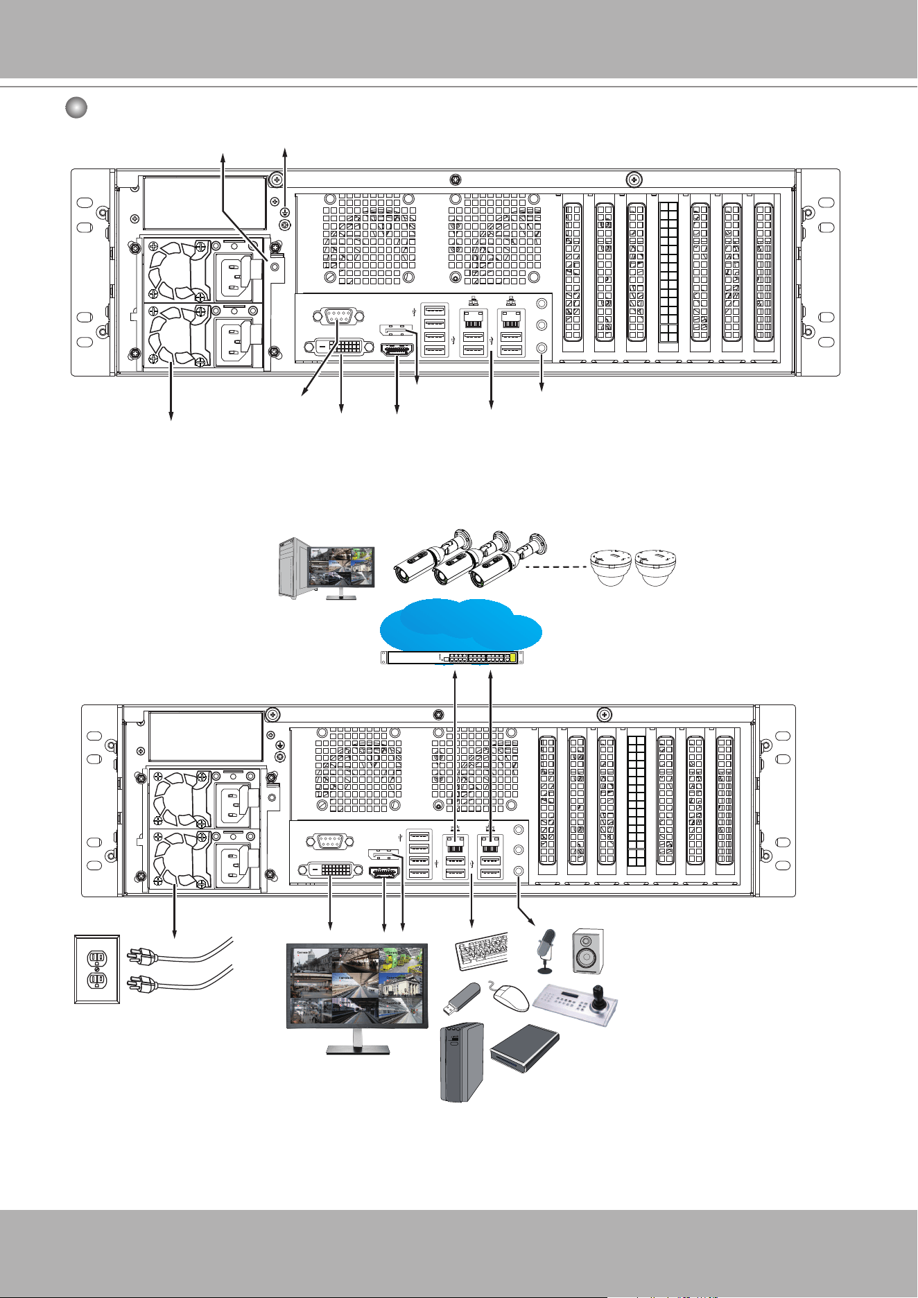
Rear View
DVI-D
LAN & USB
ports
RS232
HDMI
Display
port
Audio In/Out
Redundant power
supplies
Ground screw
Mute button
AC100~240V
~6.9A-2.8A, 50/60Hz,
+5VSB/2.5A; +12V/45A
LAN/WAN
Camera 01
Camera 02
Camera 03
Camera 04
Camera 06
Camera 05
Camera 07
Camera 08
Camera 09
Camera 01
Camera 02
Camera 03
Camera 04
Camera 06
Camera 05
Camera 07
Camera 08
Camera 09
VIVOTEK - A Leading Provider of Multimedia Communication Solutions
18 - User's Manual
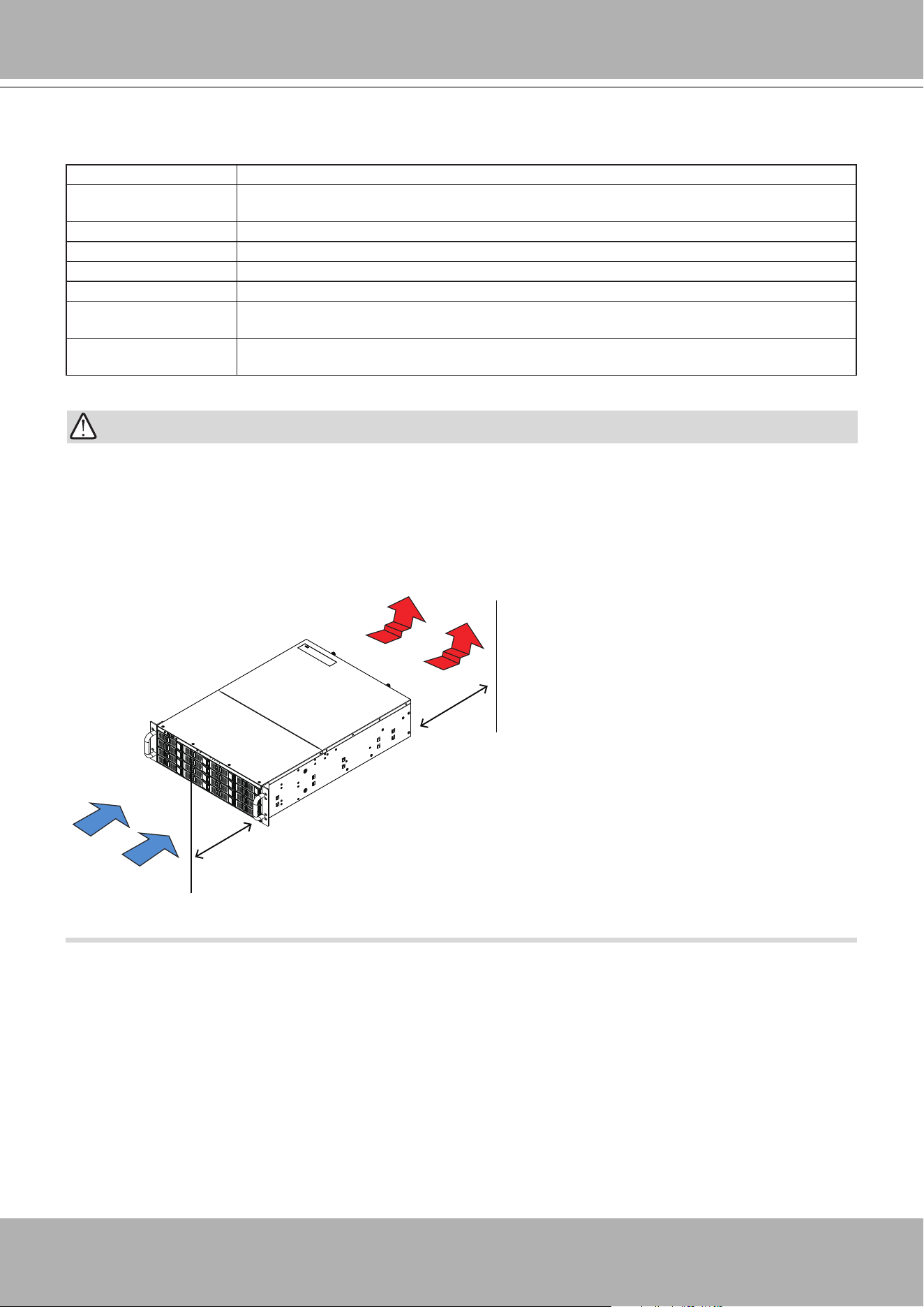
IMPORTANT:
It is important to leave a clearance of 76cm to the rear side of the chassis. The clearance is re-
quired to ensure an adequate airow through the chassis to ventilate heat. A 64cm clearance is
also required on the front of the chassis.
To ensure normal operation, maintain ambient airow. Do not block the airow around chassis
such as placing the system in a closed cabinet.
30”
76cm
25”
64cm
Display
Interface Resolution
HDMI
Supports max resolution HDMI 1.2 1920 x 1200 @ 60 Hz (Colay HDMI 2.0,4096 x 2160 @
60 Hz, optional)
DVI-D Supports max. resolution 1920 x 1200 @ 60 Hz
Display port Supports max resolution 4096 x 2304 @ 60 Hz
eDP Internal pin header, supports max. resolution 3840 x 2160 @ 60 Hz (on board)
VGA Max resolution 1920 x 1200 @ 60 Hz (on board) (optional)
Triple display eDP/ VGA + DP++ + HDMI, eDP/ VGA + HDMI + DVI-D, DP++ + eDP/ VGA + DVI-D,
DVI-D + DP++ + HDMI
Dual display DP++ + HDMI, DP++ + DVI-D, DP++ + eDP/ VGA, HDMI + DVI-D, HDMI + eDP/ VGA,
eDP, VGA + DVI-D
VIVOTEK - A Leading Provider of Multimedia Communication Solutions
User's Manual - 19
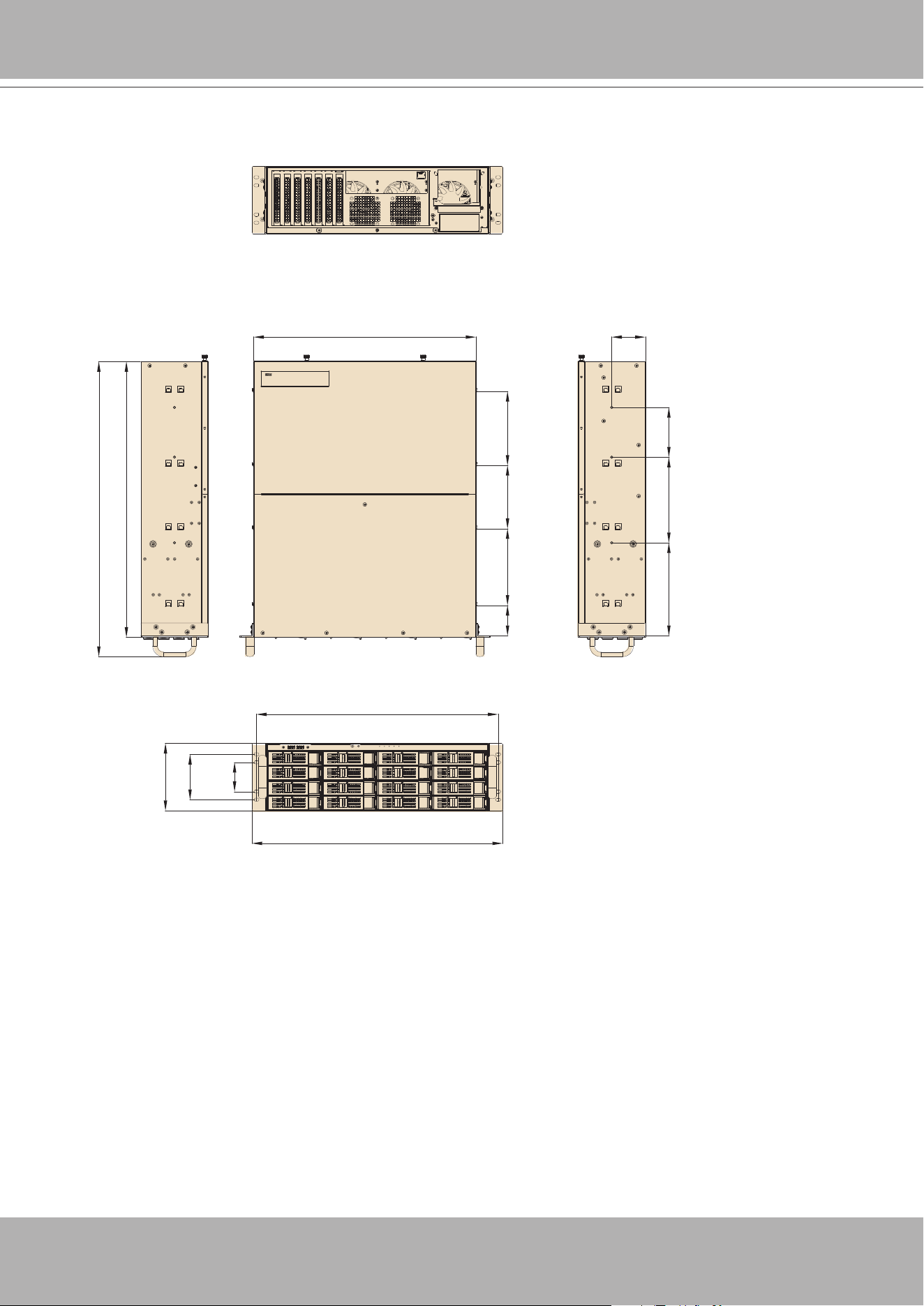
Chassis Dimensions
Unit: mm [inch]
59.5
[2.34]
150
[5.91]
124
[4.88]
145
[5.71]
473.1 [18.63]
490.6 [19.31]
57.2
[2.25]
89 [3.50]
132 [5.20]
435 [17.13] 66 [2.60]
182
[7.17]
167.7
[6.60]
97.3
[3.83]
540 [21.26]
578 [22.76]
VIVOTEK - A Leading Provider of Multimedia Communication Solutions
20 - User's Manual
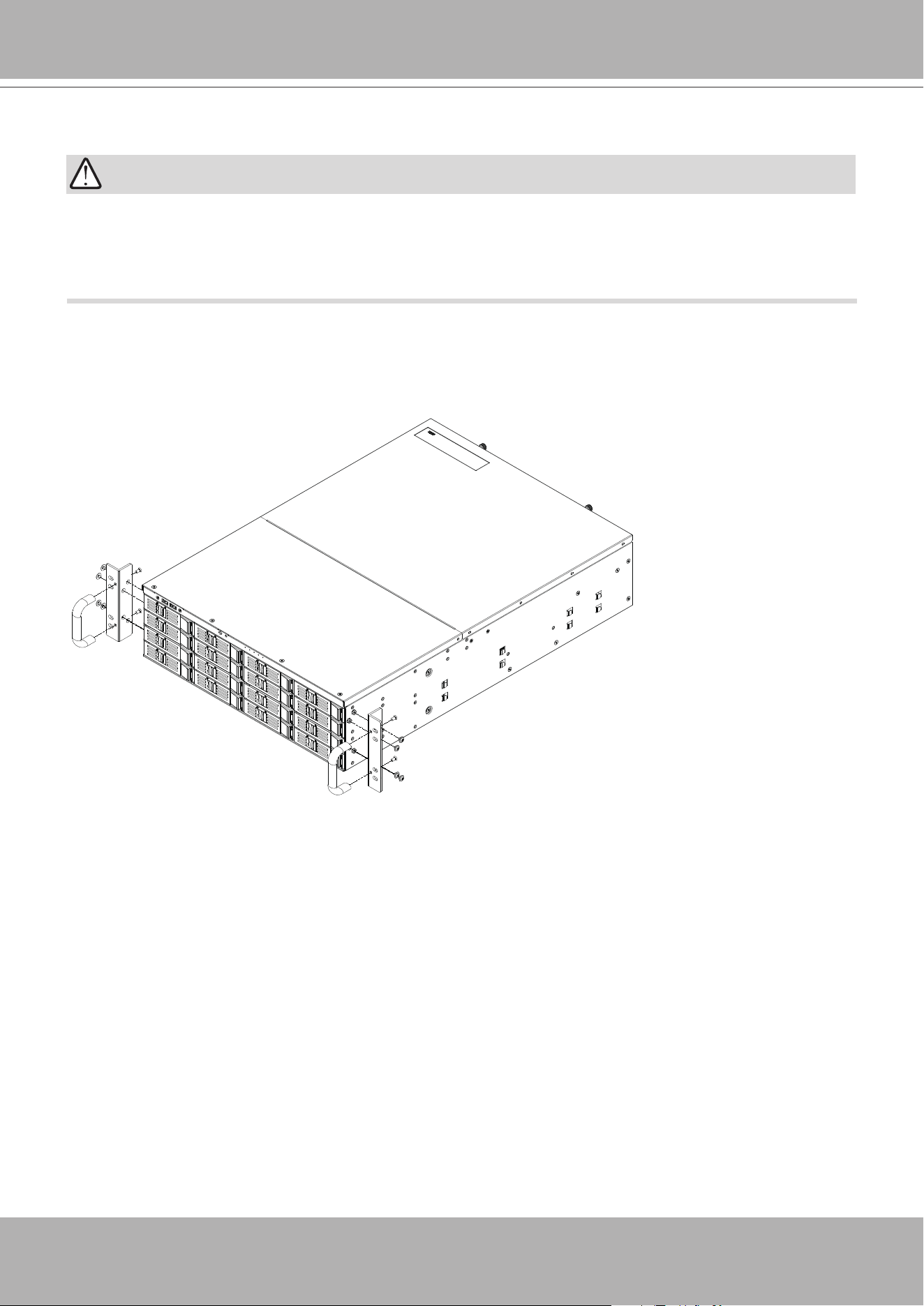
Rack-mounting
If you have either a round-holed or square-holed rack, install cage nuts or clip nuts to the
desired positions on the rack posts.
The instructions below are based on the installation to a 4-post equipment rack.
IMPORTANT:
1. There is a pair of ears and handles in the accessory box. If you need to install them, please
refer to the drawing below to fasten them to the front-right and front-left mounting ears using
the provided screws.
VIVOTEK - A Leading Provider of Multimedia Communication Solutions
User's Manual - 21
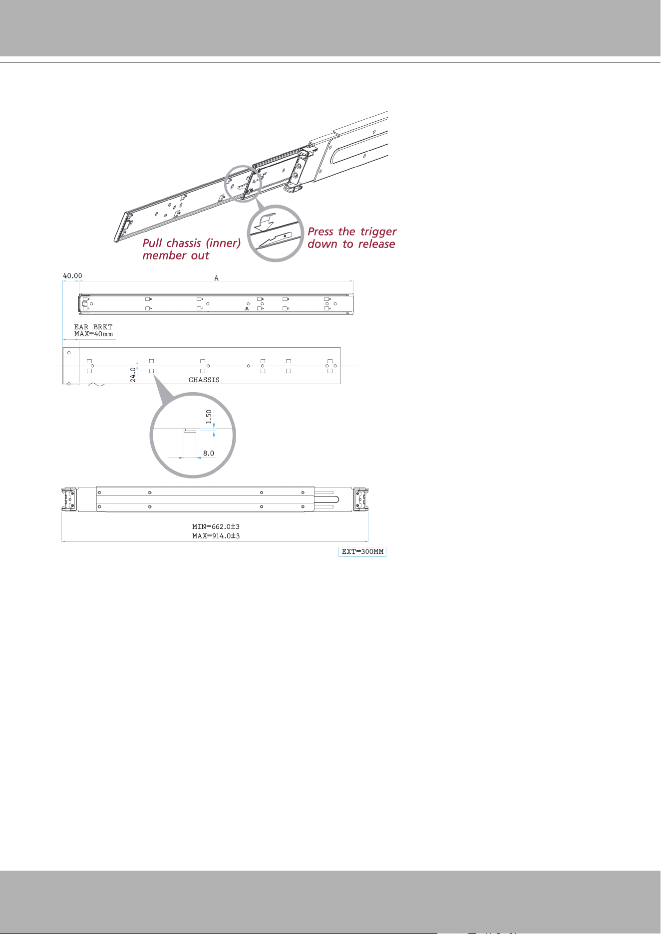
2. Remove the inner rail from the slide rail assembly.
VIVOTEK - A Leading Provider of Multimedia Communication Solutions
22 - User's Manual
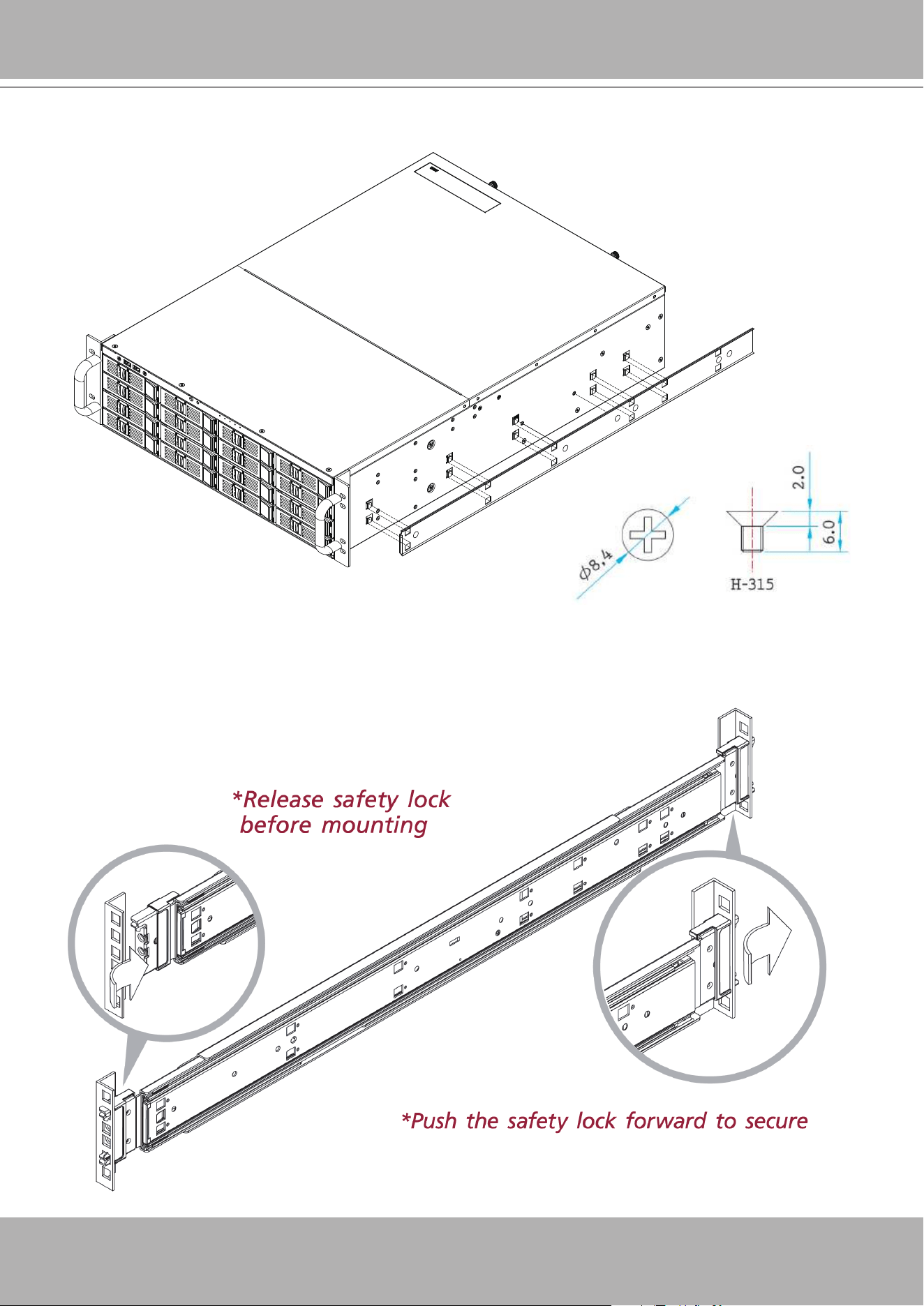
3. Secure the inner rails to the sides of the chassis using the included screws.
4. Insert the stag into the upper and lower square holes on the EIA rail from the back of the rail.
Push the safety lock forward to secure the bracket. .
VIVOTEK - A Leading Provider of Multimedia Communication Solutions
User's Manual - 23
It is important to check if the safety lock is in the unlocked position before mounting the brackets.
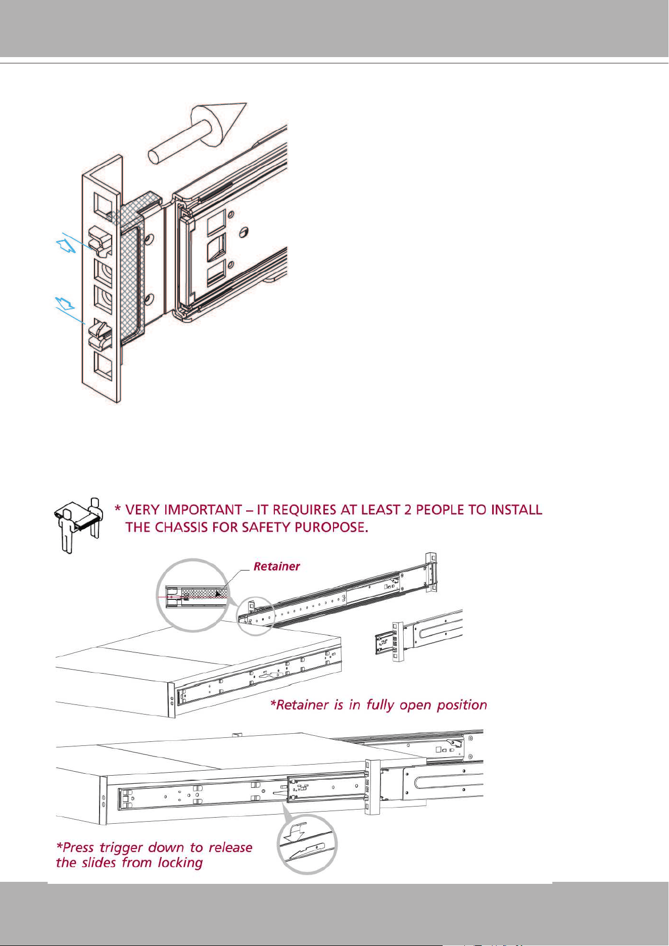
5. Lift and insert the chassis into the rack cabinet as shown below. It is important to check if the
ball bearing retainer is in the fully open position before installing the chassis or it might cause
catastrophic damage to the chassis if the ball bearing retainer is not in the fully open position
while mounting the chassis. While you are pushing the chassis into the cabinet, you will need
to release the slide from the locking position by pressing the trigger down.
VIVOTEK - A Leading Provider of Multimedia Communication Solutions
24 - User's Manual
• Refer to VIVOTEK's website for the hard disk compatibility information.
• Avoid touching the hard drive's circuit board or connector pins. Doing so can damage the
hard drive by electro-static discharge.
IMPORTANT:
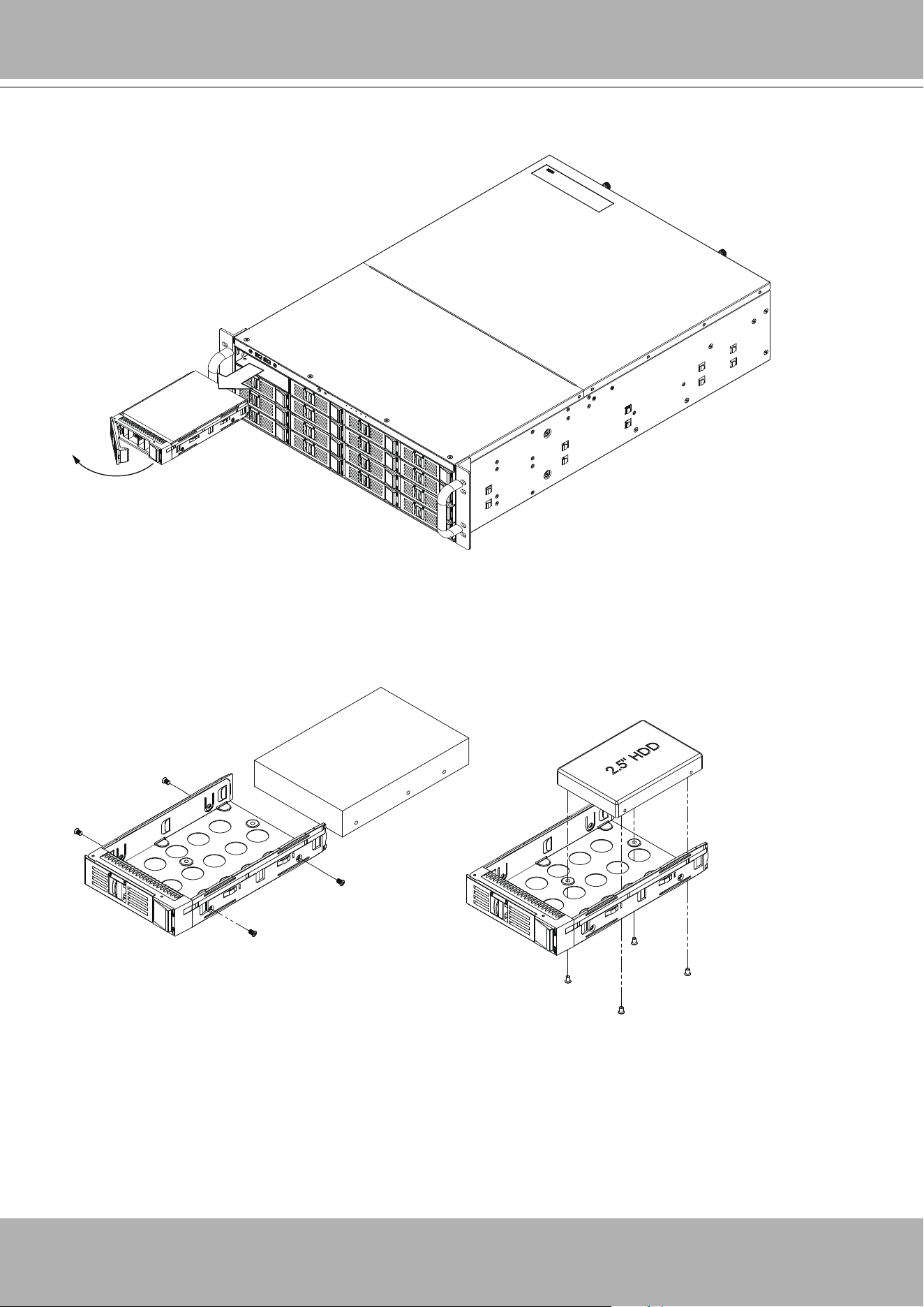
Installing Hard Disk Drives
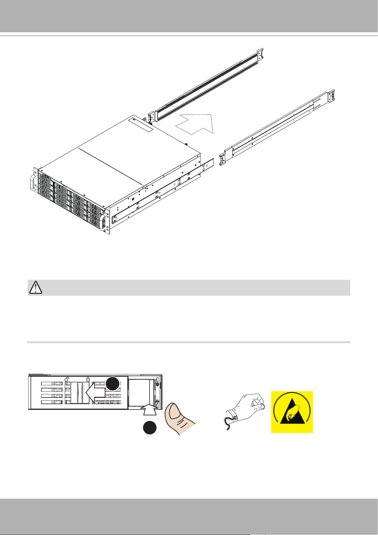
1. Remove drive trays from the chassis. Push the bezel lock to the left, and then press the
release tab. The tray lever will pop out.
ESD
It is recommended to wear an anti-static
wrist strap when handling hard drives.
1
2
VIVOTEK - A Leading Provider of Multimedia Communication Solutions
User's Manual - 25
2. Pull the lever to remove drive trays.
3. Install hard drives by driving screws from the sides. When done, gently install the drive trays
into the chassis.
VIVOTEK - A Leading Provider of Multimedia Communication Solutions
26 - User's Manual
Connecting Interfaces
Refer to page 15 for the interface connections.
1. Make sure all cameras have been properly installed, either they are powered by 12V
power lines or using one or several PoE switches or mid-spans. Refer to the cameras'
documentation for details.
2. Connect all other interfaces to USB mouse/keyboard, one or two monitors, and audio input/
output devices.
3. Make sure you connect both power supplies to power mains.
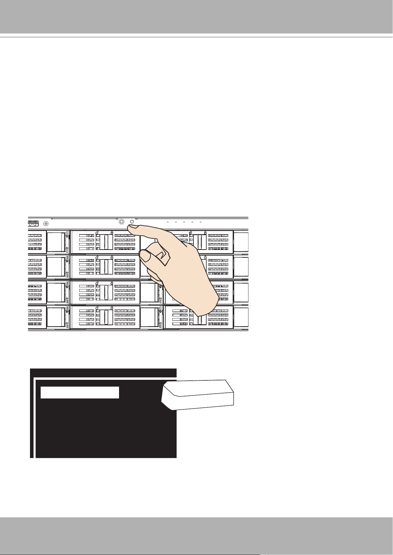
Initial Conguration
1. Power up the system by pressing the power on button.
2. Skip the BIOS screens and select
Enter NVR
at the selection screen. The system will start.
Wait for the start-up process to complete.
0 Enter NVR
1 Restore to default
2 Reboot
3 Shutdown
Enter
VIVOTEK - A Leading Provider of Multimedia Communication Solutions
User's Manual - 27
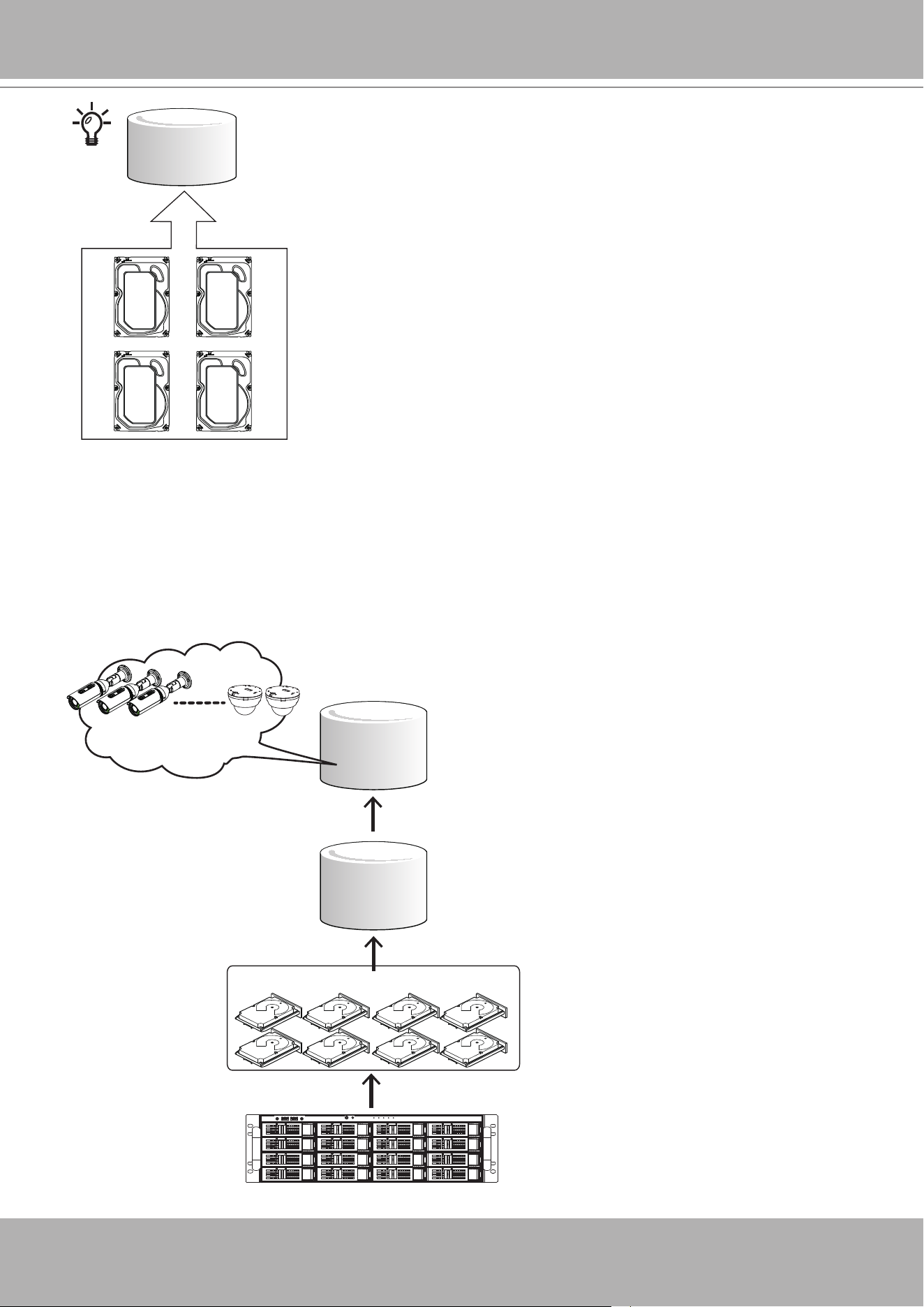
RAID5/6/10
Drive Group
Virtual Drive
Our default recommendation is to combine 4 hard drives into 1 drive group. The capacities of
these drives will be utilized to form 1 Virtual Drive. If all 16 drive bays are populated, you can
create 4 Virtual Drives. A 4-member Virtual Drive can receive the video feeds from 32 cameras.
You can also create two 8-member Virtual Drives to receive the video feeds from 64 cameras (CH,
or channels.)
Recording will not take place unless you create a Virtual Drive rst. Select RAID5 as the RAID
level during the conguration process.
Virtual Drive
Drive Group
LUN - Volume
x2
8 members (RAID5)
64 CH,
each LUN
VIVOTEK - A Leading Provider of Multimedia Communication Solutions
28 - User's Manual
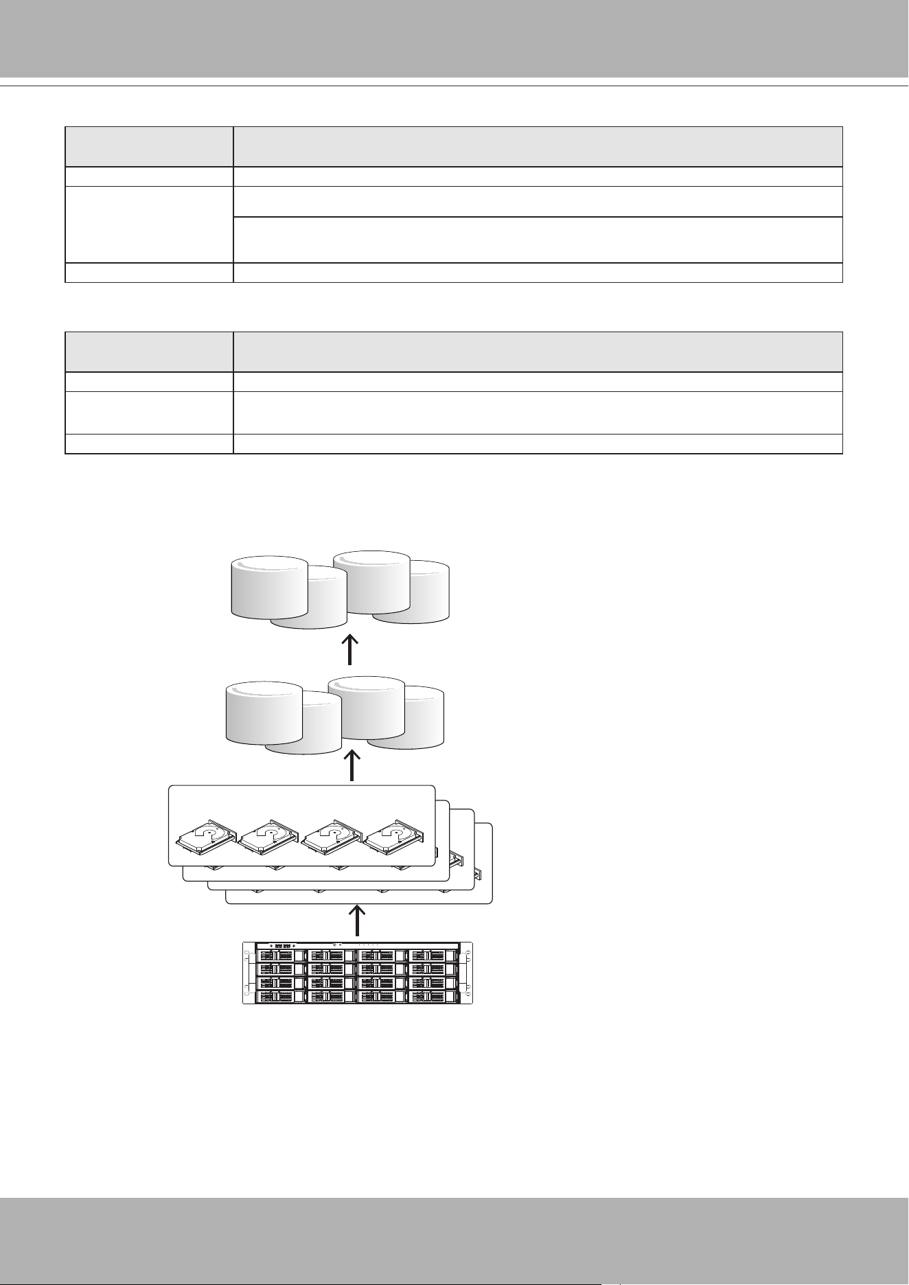
The default conguration for a conguration of 128 cameras should look like the following:
Physical & Logical
components
Conguration
Hard drive 16
Virtual Drive 4, each has 4 members. Congured in RAID5.
If using 6TB drives, the available capacity in each Virtual Drive will be,
4 x 6TB-1 x 6TB(parity drive)= 18TB.
Volume 4, each created from 1 Virtual Drive.
The camera conguration should look like this,
Physical & Logical
components
Conguration
Cameras 128
Recording Group 4, each responds to 32 cameras, and each Recording Group is associated with 1 Virtual
Drive volume.
Volume 4, each created from 1 Virtual Drive, and associated with 1 Recording Group. .
Virtual Drive
Drive Group
LUN - Volume
x4
4 members
4 members
4 members
x4
x4
4 members (RAID5)
A Virtual Drive appears to the host system (Windows) as a logical disk partition. The logical
parition, when formatted, becomes a disk volume.
VIVOTEK - A Leading Provider of Multimedia Communication Solutions
User's Manual - 29
X2
X2
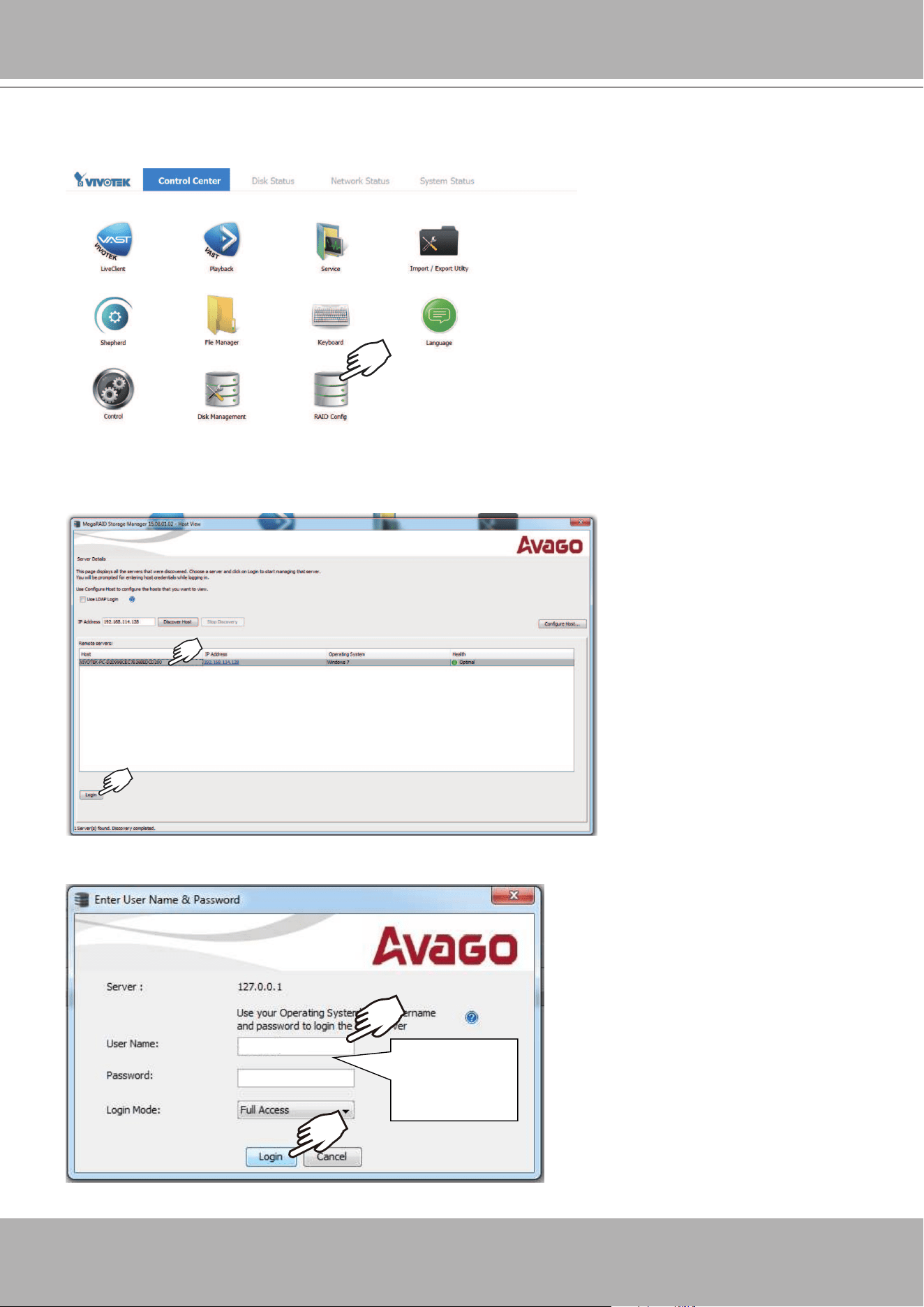
1. The system will boot up to the system main screen. Double-click on the
RAID Cong
shortcut
to start the MegaRAID storage conguration utility.
2. Select the default server, namely, the Windows 7 server running on this machine. Click Login
to begin your conguration.
3. Enter
vivotek/vivotek
as the User Name and Password. Click Login to proceed.
vivotek
vivotek
Default:
vivotek
vivotek
VIVOTEK - A Leading Provider of Multimedia Communication Solutions
30 - User's Manual
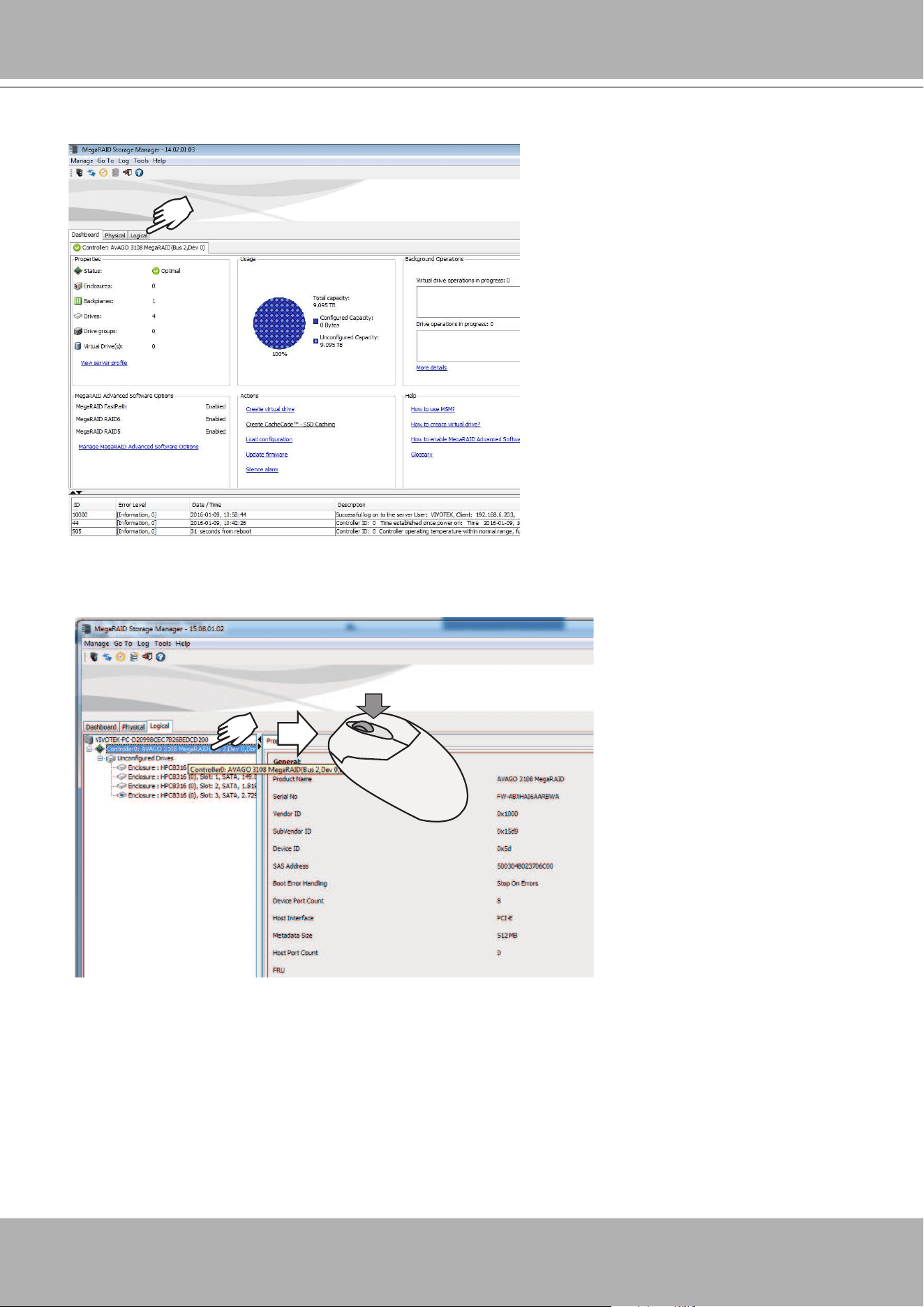
4. A Dashboard view will appear. Click the
Logical
tab.
5. Left-click to select the AVAGO MegaRAID controller, and then right-click to display a
command menu.
VIVOTEK - A Leading Provider of Multimedia Communication Solutions
User's Manual - 31
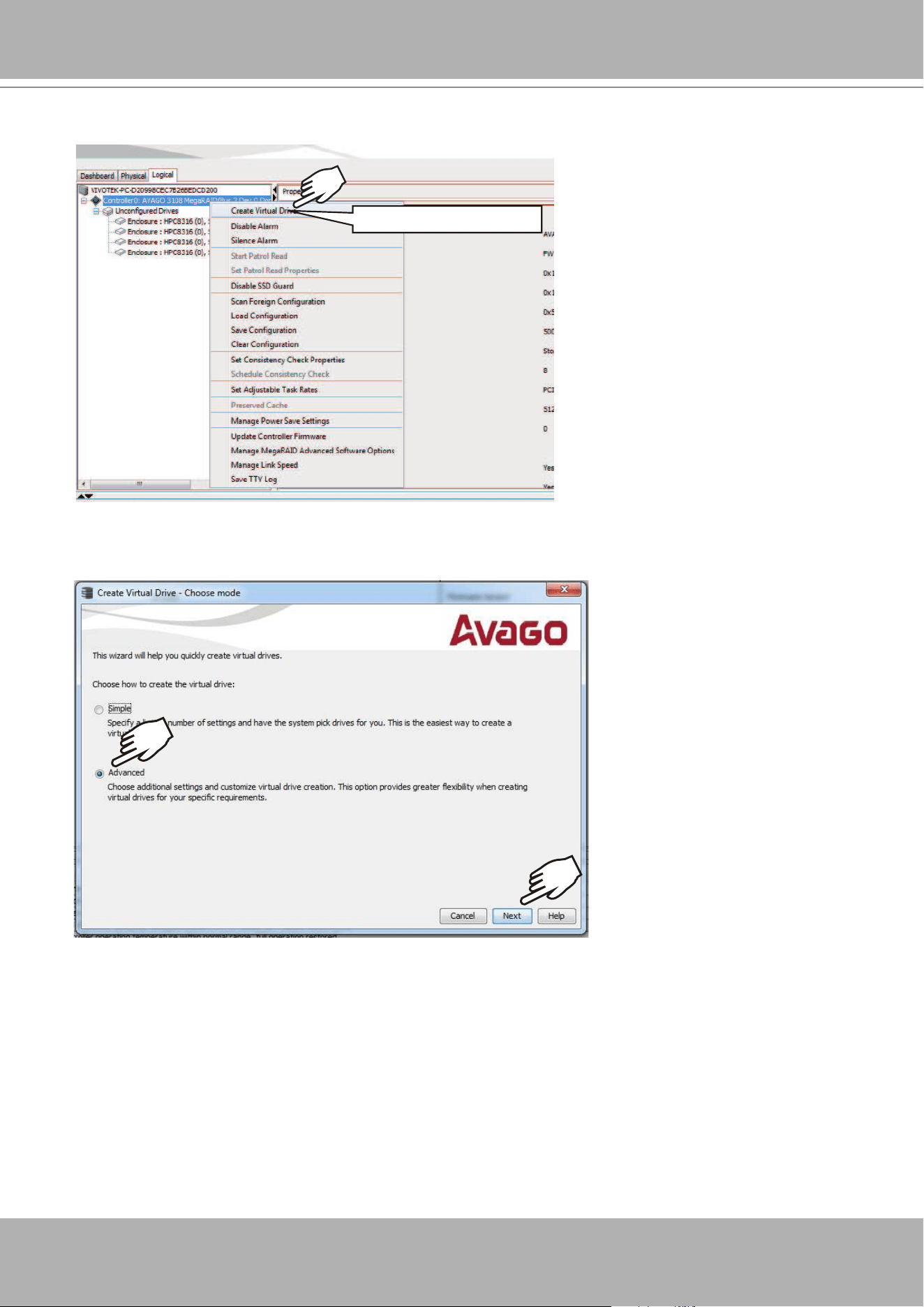
6. Click on
Create Virtual Drive
.
Create Virtual Drive
7. The
Create Virtual Drive
wizard will start. Click to select the
Advanced
mode. Then click the
Next button to proceed.
VIVOTEK - A Leading Provider of Multimedia Communication Solutions
32 - User's Manual
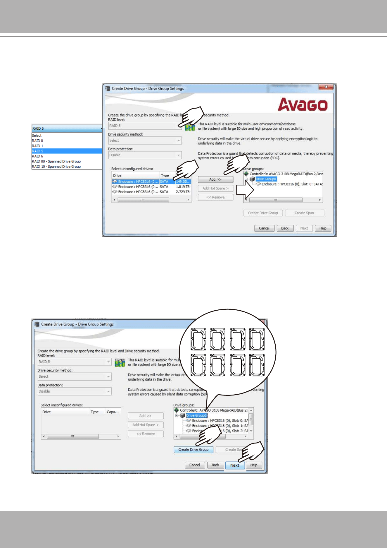
8. Select a
RAID level
, and then select multiple disk drives as the members of your drive group.
Left-click to select a disk drive, and click
Add
to add it to group. You do not need to select the
Data protection option.
9. Click on the Drive Group 0 entry you have just congured. The
Create Drive Group
button
will become available. Click Next to proceed.
Refer to the next section:
RAID Basics
on page 45, for details about RAID levels.
VIVOTEK - A Leading Provider of Multimedia Communication Solutions
User's Manual - 33
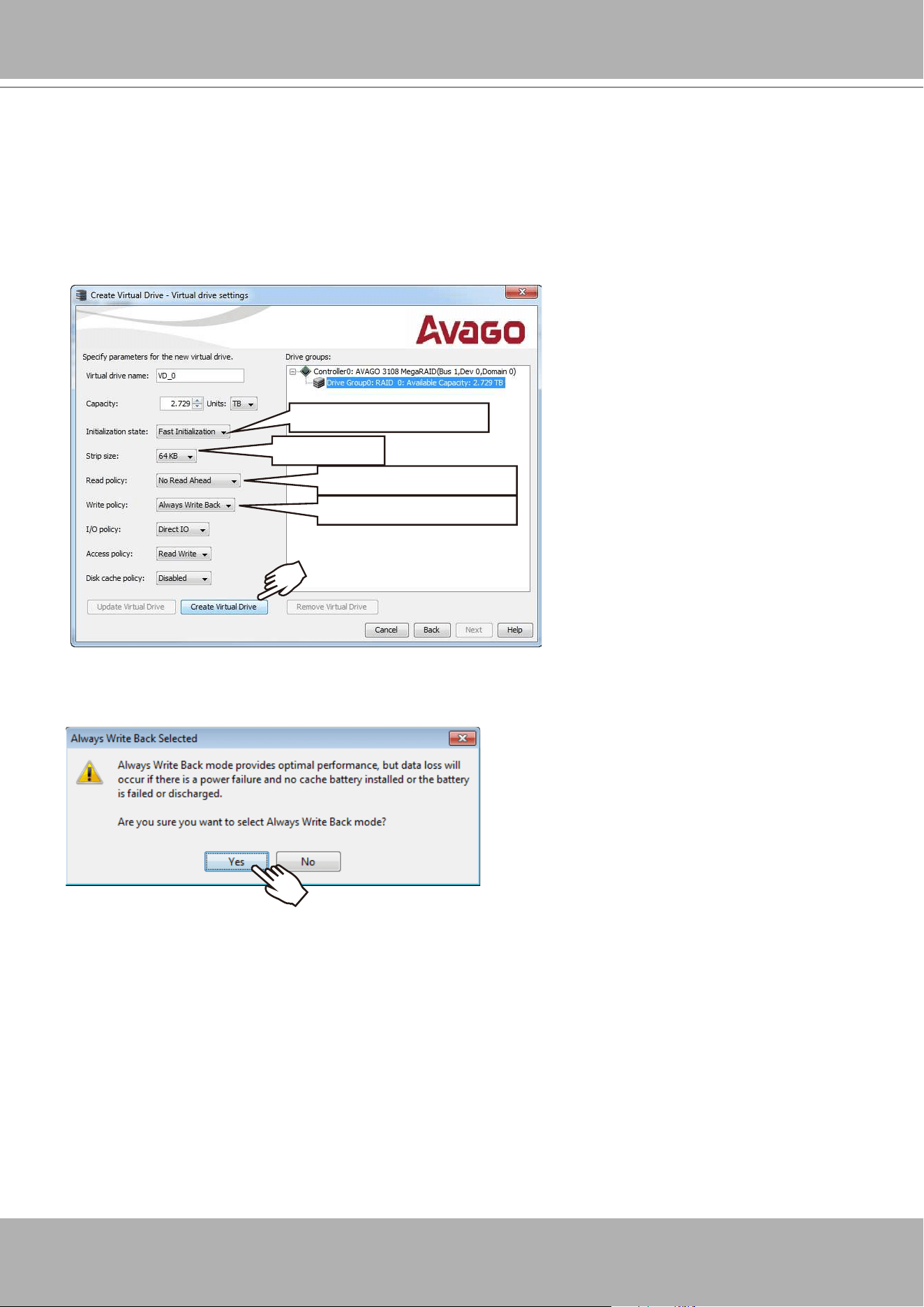
9. Select the following key parameters:
Initialization State:
Fast Initialization
, Strip size:
64KB
, RAID policy:
No Read Ahead
,
Write policy:
Always Write Back
.
These are important parameters to the disk array performance, and have to be correctly
congured. Click
Create Virtual Drive
.
10. Click
Yes
to leave the Write Back concern message.
64 KB
No Read Ahead
Always Write Back
Fast Initialization
VIVOTEK - A Leading Provider of Multimedia Communication Solutions
34 - User's Manual
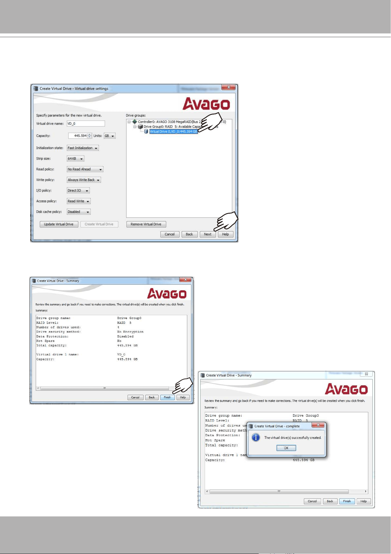
11. The wizard may prompt for another virtual drive. Multiple virtual drives can be created from
a physical drive group. Repeat the process to create more 4-member Virtual Drives. When
done, click to select the
Virtual Drive 0,VD_0
, and then click Next to proceed.
12. The Virtual Drive is instantly created. Click
OK
, and then click
Finish
to close the wizard.
You can then terminate the MegaRAID utility.
VIVOTEK - A Leading Provider of Multimedia Communication Solutions
User's Manual - 35
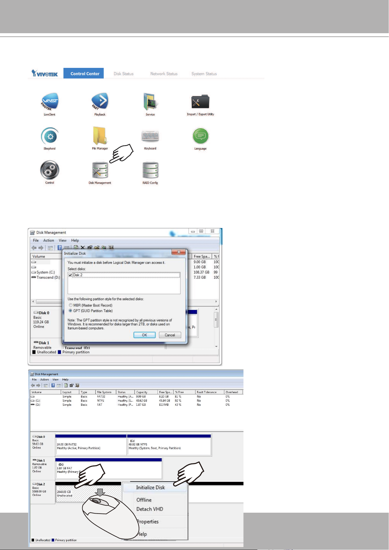
13. Double-click on the
Disk Management
shortcut on the desktop to open the utility.
X2
14. The virtual drive you created should appear as a new disk partition. You need to initialize
and format the partition before using the disk capacity. Left-click to select and then right-click
to display the command menu. Click
Initialize Disk
to proceed.
VIVOTEK - A Leading Provider of Multimedia Communication Solutions
36 - User's Manual
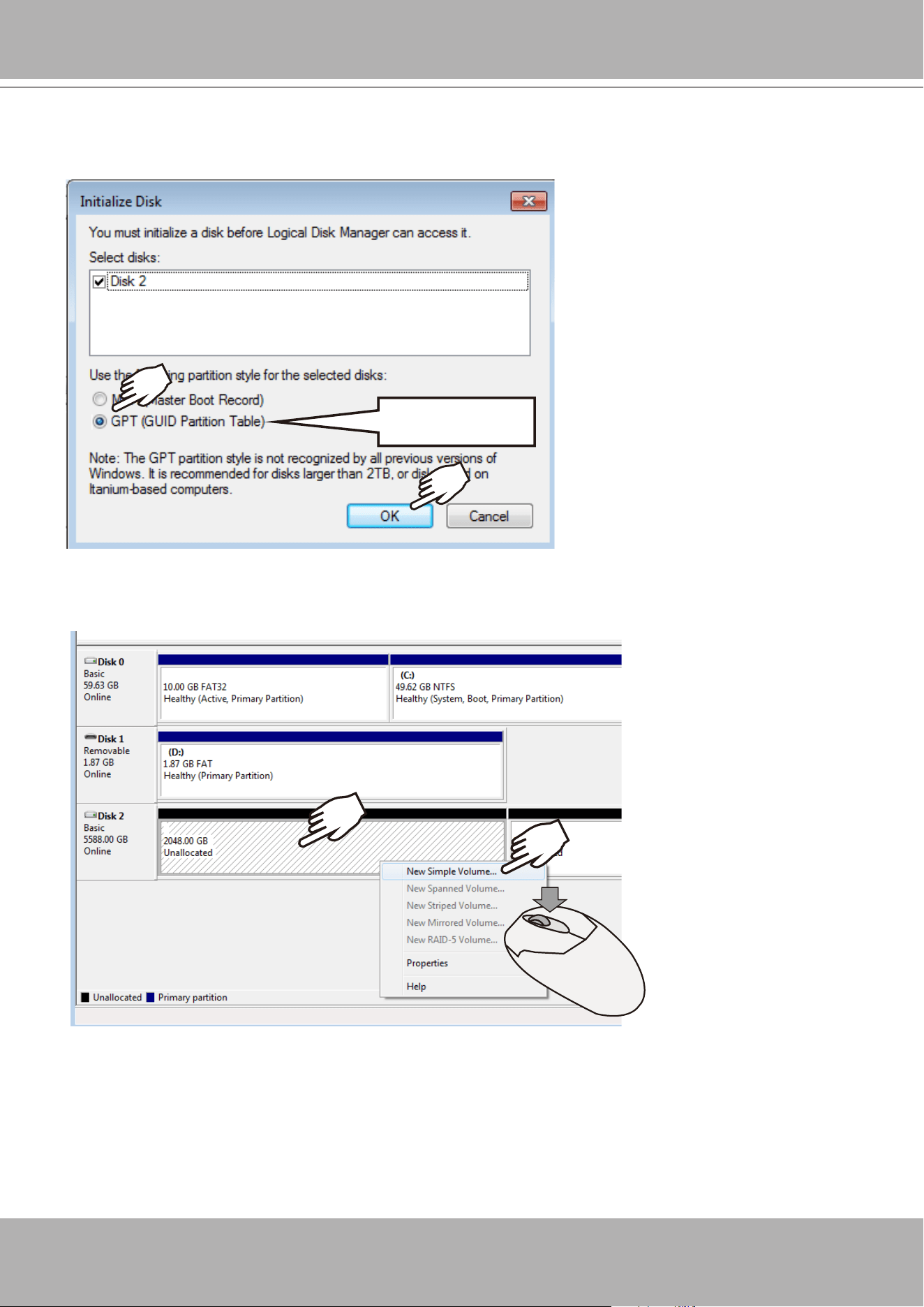
15. Select
GPT
(GUID Partition Table), and then click
OK
to proceed. This window may
automatically pop up when Disk Management is started.
GPT
16. Once initialized, you can create a new volume
.
Right-click to display the
New Simple
Volume
command. Click to proceed.
VIVOTEK - A Leading Provider of Multimedia Communication Solutions
User's Manual - 37
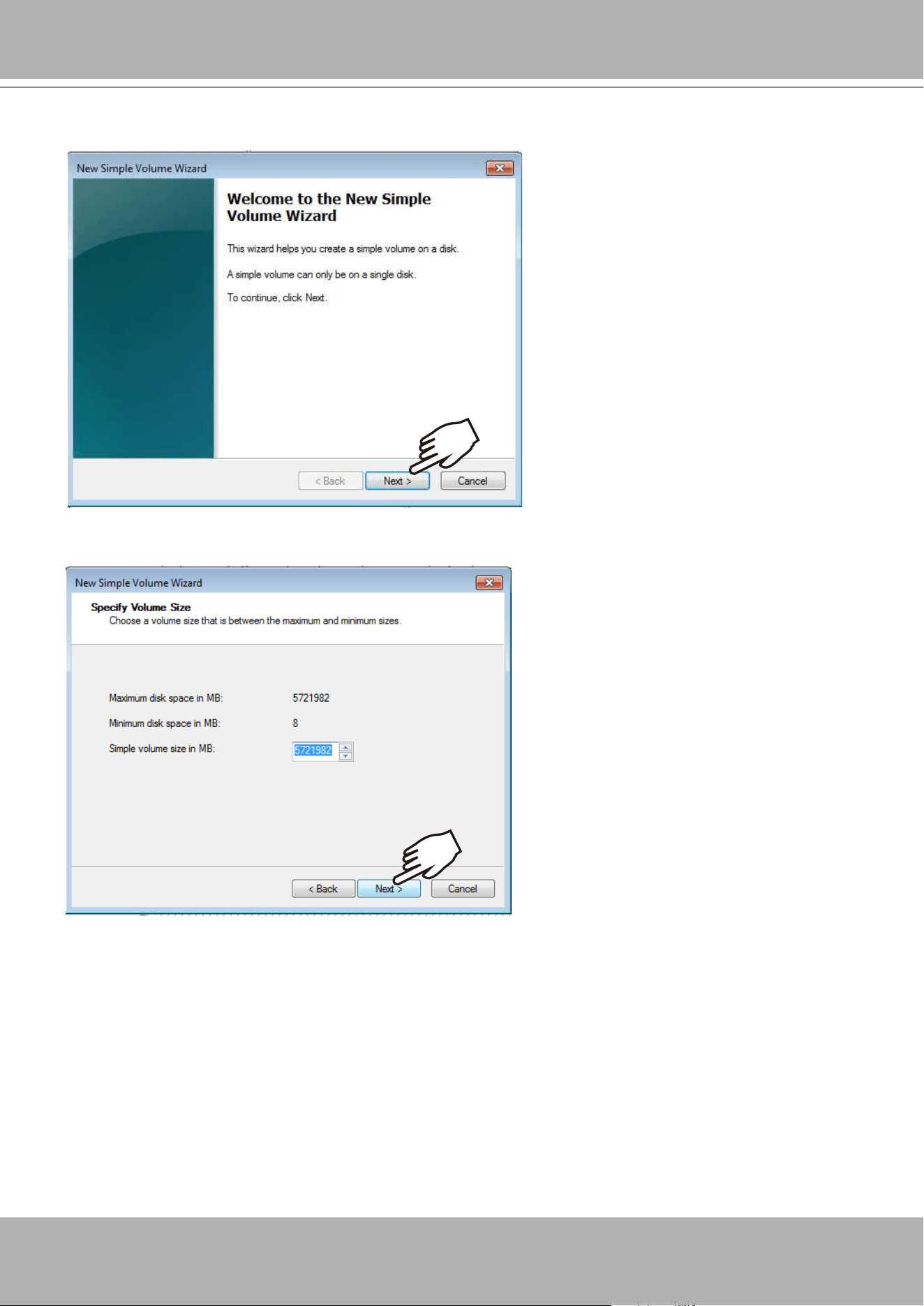
17. The
New Simple Volume
Wizard will prompt
.
Click Next to proceed.
18. Leave the volume size unchanged. Click Next to proceed.
VIVOTEK - A Leading Provider of Multimedia Communication Solutions
38 - User's Manual
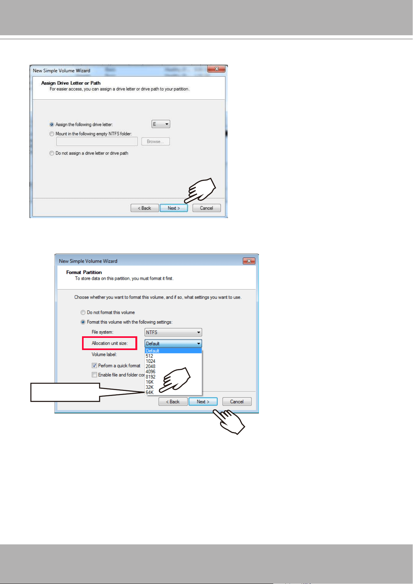
20. On the
Format Partition
page, select the
Allocation unit size
as
64KB
. When done, click
Next to proceed.
64 KB
19. When prompted to assign a drive letter, click Next to proceed.
VIVOTEK - A Leading Provider of Multimedia Communication Solutions
User's Manual - 39
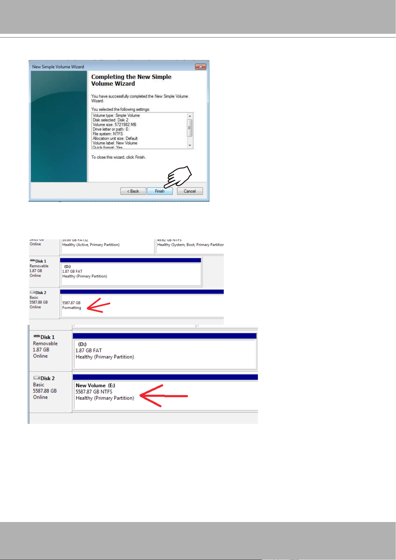
21. Click Finish to end the wizard.
22. The formatting process will run in the background. When done, the new volume shall be
indicated as a healthy new volume. Close the Disk Management window.
VIVOTEK - A Leading Provider of Multimedia Communication Solutions
40 - User's Manual
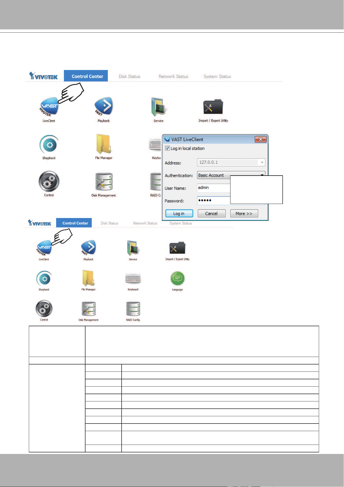
23. Start VIVOTEK
LiveClient
utility by double-clicking its shortbut. Enter
admin
and
admin
as
the User Name and default Password. You can change the password later in the utility. Click
Log in to proceed.
X2
X2
Top row Control Center: the default desktop.
Disk Status: Displays the current storage volume status (system drive and RAID volumes).
Network Status: Displays the information for the current network connections.
System Status: Displays the current system status, license information, and VAST service.
Desktop Shortcuts
LiveClient
Starts the VAST LiveClient utility.
Playback Starts the VAST Playback utility.
Service Enables you to start, stop, or restart the VAST server instance.
Import/Export Allows you to import or export VAST congurations.
Shepherd Use the Shepherd utility to locate cameras within your network.
File Manager Provides access to the les in system disk drive volumes.
Keyboard Toggles the virtual keyboard in case you do not have a physical keyboard.
Language Changes the UI language. .
Control Opens the operating system's control panel.
Disk
Managment
Starts the Disk Management utility in Windows.
RAID Cong. Starts the RAID card storage conguration utility.
admin
admin
VIVOTEK - A Leading Provider of Multimedia Communication Solutions
User's Manual - 41
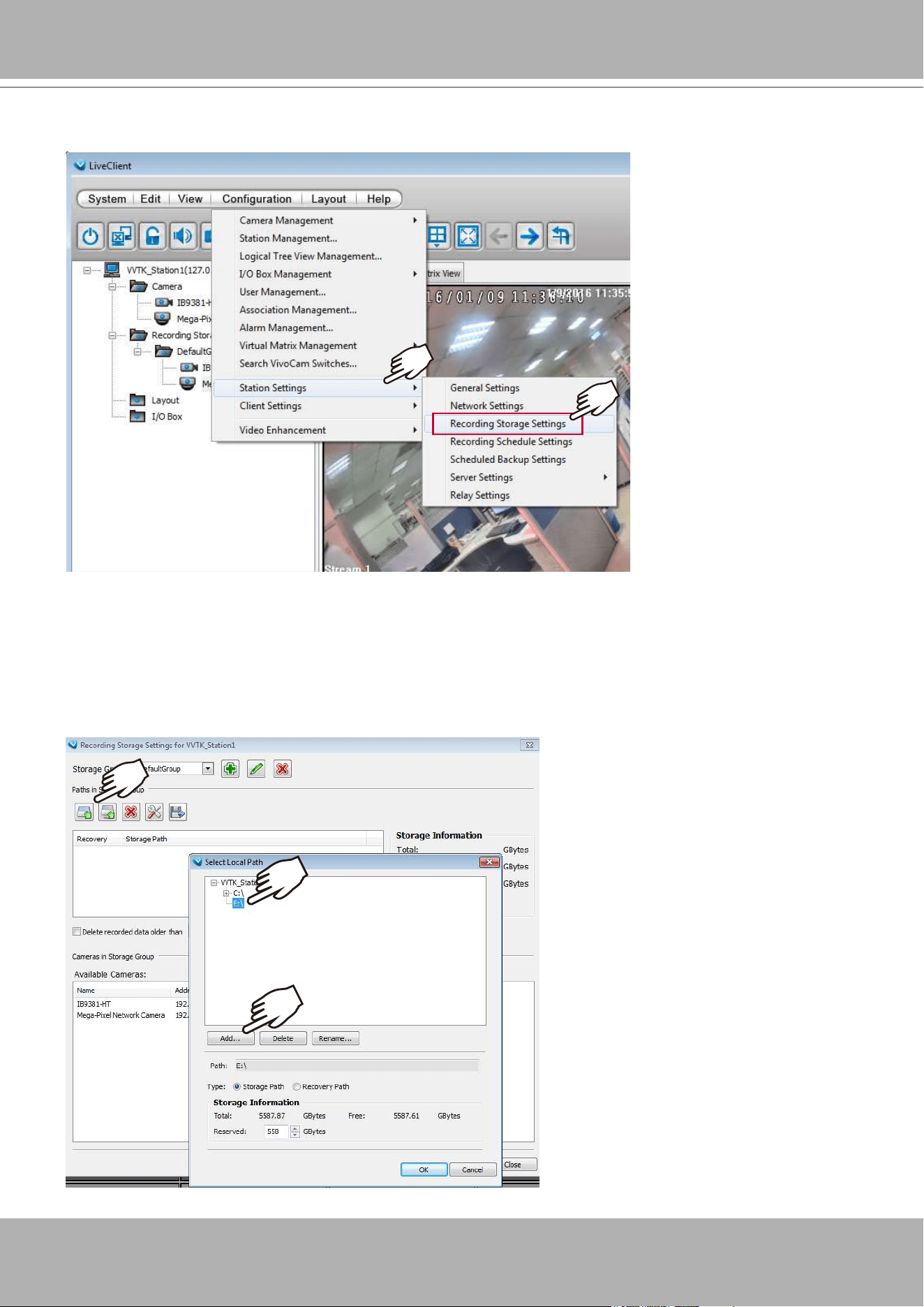
24. Click
Conguration
>
Station Settings
>
Recording Storage Settings
.
25. Click on the
Add Local Path
button
.
Select the new local path displayed as D:/ or E:/ drive
(your new volume). Click OK to proceed.
Since you cannot record video to the root directory, click
Add
to create a new folder, e.g., D:\
Recording.

VIVOTEK - A Leading Provider of Multimedia Communication Solutions
42 - User's Manual
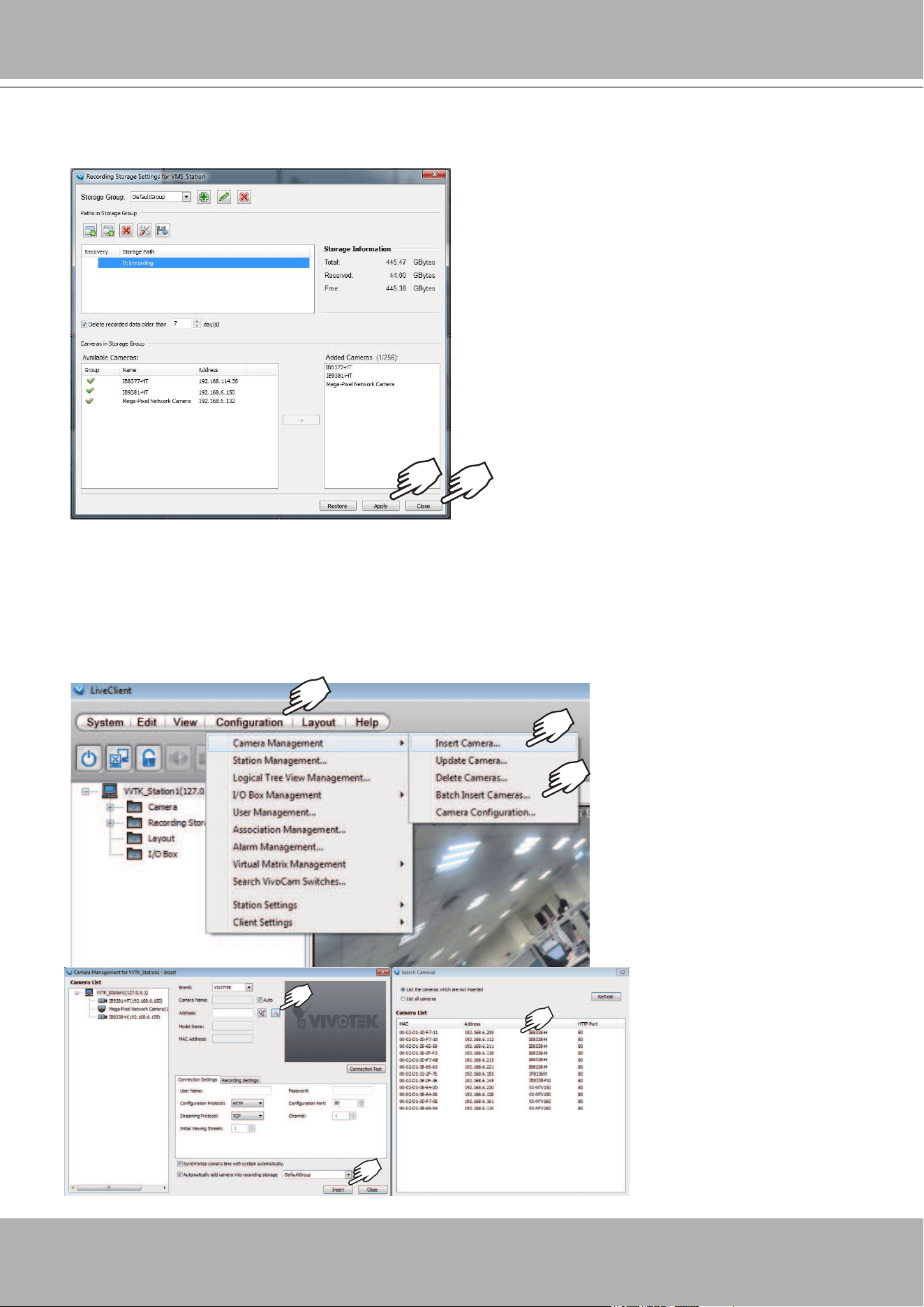
26. Enter a name for the new folder, e.g., Recording.
27. Select the new folder you just created and click
OK
button
.
VIVOTEK - A Leading Provider of Multimedia Communication Solutions
User's Manual - 43
28. The selected
Storage path
will appear on the list along with its total, reserved, and Free
storage spaces information. Click Apply.
29. Open the
Camera Management > Insert Camera
or
Batch Insert Cameras
window.
Use the
Search
button to locate cameras in your local area network. Select and click
Insert
.
Select and insert all cameras of your choice in your deployment, and then close the Camera
Management window.
VIVOTEK - A Leading Provider of Multimedia Communication Solutions
44 - User's Manual
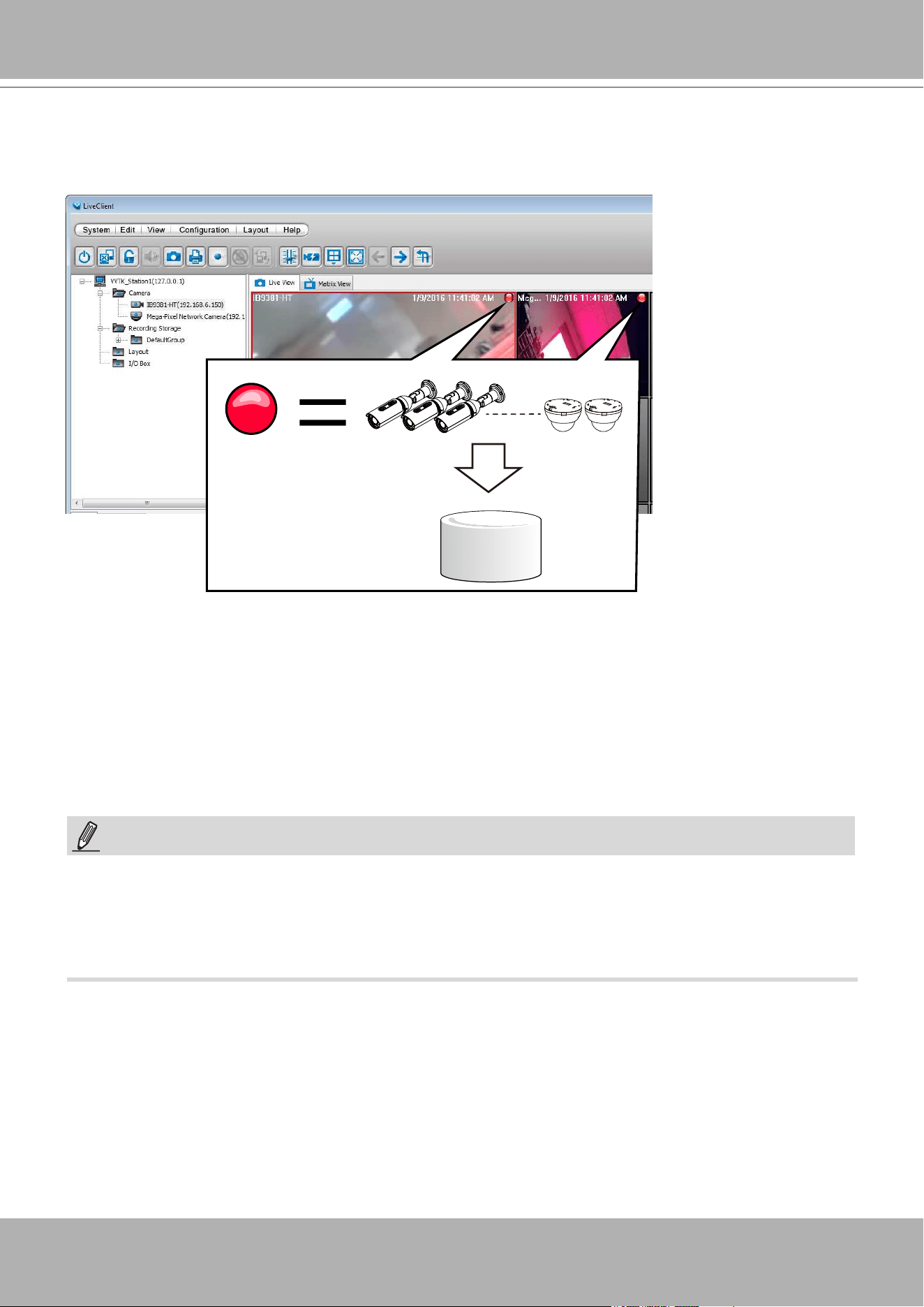
30. You will return to the
Live View
window. By default, once cameras have been inserted and
the storage path is ready, the NVR starts recording the video streams. Note the red light icons
on the view cells. If red icons appear on the view cells, recording is taking place.
Virtual Drive
31. You are done with the initial conguration. Refer to the rest of the manual for the congurable
options in the VAST management software.
1. Cameras and the NVR must reside in the same subnet. Otherwise, the NVR will not be able
to recruit them into a recording conguration.
2. It is recommended all network cameras use static IPs. If you let a DHCP server assign IPs to
these cameras, IPs may be changed later and the NVR may not recognize them.
NOTE:

VIVOTEK - A Leading Provider of Multimedia Communication Solutions
User's Manual - 45
RAID Basics
A Redundant Array of Independent Disks is an array, or group, of multiple independent physical
drives that provide high performance and fault tolerance. A RAID drive group improves I/O
performance and reliability. The RAID drive group appears to the host computer as a single
storage volume or as multiple virtual units. An I/O transaction is expedited because several
drives can be accessed simultaneously.
A RAID drive group improves data storage reliability and fault tolerance compared to single drive
storage. Data loss resulting from a drive failure can be prevented by reconstructing missing data
from the remaining drives. The benets of RAID come from the improvement of I/O performance
and the increased reliability.
What are the Virtual drives?
Virtual drives are drive groups that are available to the operating systems. The storage space in
a virrtual drive comes from all the members in the drive group.
The RAID functions available for virtual drives include:
Hot spare drives.
Drive group and virtual drive congurations.
Initializing one or more virtual drives.
Individual access to controllers, virtual drives, and disk drives.
Failed drive rebuild.
Verication of redundancy data in virtual drives using RAID levels 1, 5, 6, 10, 50, and 60.
Reconstructing virtual drives after the RAID levels or adding a drive to a drive group.
Indepently selecting a host controller to work for.
RAID conguration components
Drive group: a group of physical drives. These drives will be managed in partitions known as
virtual drives.
Virtual drive: a partition in a drive group made of continguous data segments from the
individual disk drives. A virtual drive can consist of the following components:
An entire drive group.
More than one entire drive group.
A part of drive group.
Parts of more than one drive group.
A combination of any two of the conditions above.
For a RAID volume conguration, it is recommended you use hard drives of the same model
featuring the same capacity and rotation speed. It is also preferred that these drives are running
the same version of rmware.
IMPORTANT:
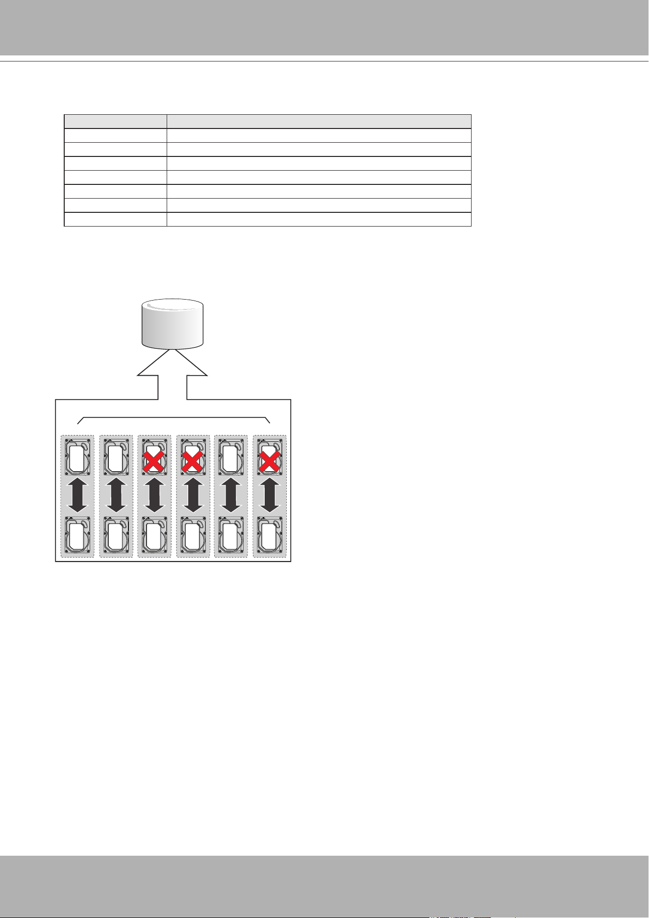
VIVOTEK - A Leading Provider of Multimedia Communication Solutions
46 - User's Manual
RAID Fault Tolerance
RAID Level Number of Tolerable Drive Failures
0 No fault tolerance
1 1, each drive group
5 1
6 2
10 multiple, as long as each failure is in a separate drive group
50 1 in each drive group
60 2 in each drive group
RAID10
Mirror
Mirror
Mirror
Mirror
Mirror
Mirror
RAID0
RAID1 RAID1 RAID1 RAID1 RAID1 RAID1
For example, if disk failure occurs in different drive groups, a RAID10 conguration can
tolerate multiple drive failures. In each RAID1 drive group, data is mirrored to a counterpart
disk drive. Data remains intact if one disk drive should fail in each drive group.
Consistency Check
The consistency check operation veries the correctness of the data in virtual drives that use
RAID levels 1, 5, 6, 10, 50, and 60. RAID0 does not provide data redundancy. In a system with
parity, check consistency means calculating the data on one drive and comparing the results to
the contents of the parity drive.
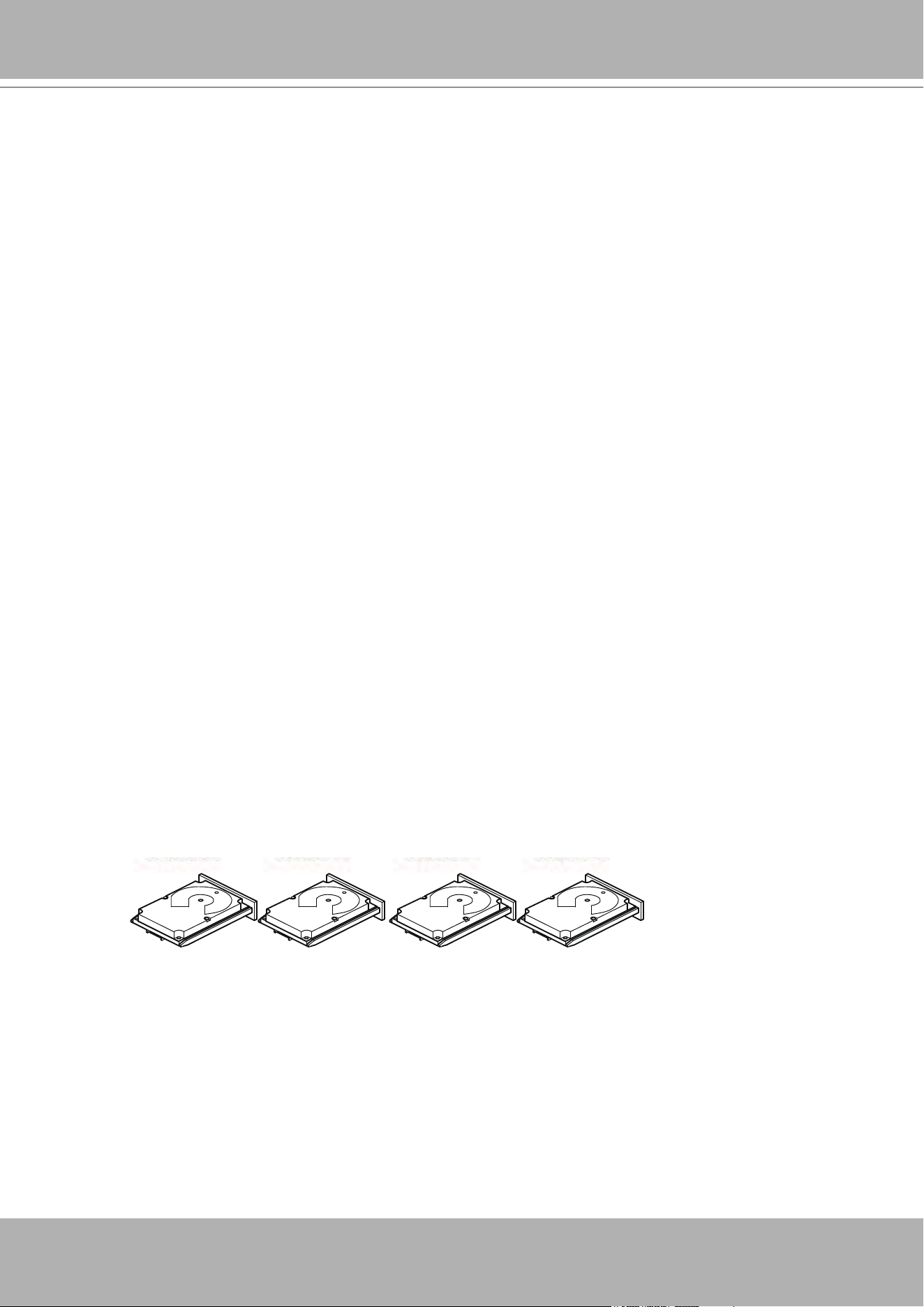
VIVOTEK - A Leading Provider of Multimedia Communication Solutions
User's Manual - 47
Background Initialization
Background initialization is a check for media errors on the drives when you create a virtual
drive. It is an automatic operation that starts ve minutes after you create a virtual drive. This
check ensures that striped data segments are the same on all of the drives in the drive group.
Background initialization is similar to a consistency check. The difference between the two is
that a background initialization is forced on new virtual drives and a consistency check is not.
New RAID 5 virtual drives and new RAID 6 virtual drives require a minimum number of drives
for a background initialization to start. If fewer drives exist, the background initialization does not
start. The background initialization needs to be started manually. The following number of drives
are required:
New RAID 5 virtual drives must have at least ve drives for background initialization to start.
New RAID 6 virtual drives must have at least seven drives for background initialization to
start.
The default and recommended background initialization rate is 30 percent. Before you change
the rebuild rate, you must stop the background initialization or the rate change will not affect the
background initialization rate. After you stop background initialization and change the rebuild
rate, the rate change takes effect when you restart background initialization.2.1.7Patrol Read
Disk Striping
Disk striping lets you write data across multiple drives instead of just one drive. Disk striping
involves partitioning each drive storage space into stripes that can vary in size from a minimum
of 64 KB to 1 MB for MegaRAID controllers and 64 KB for Integrated MegaRAID controllers. The
LSISAS2108 controller allows stripe size from 8 KB to 1 MB. These stripes are interleaved in
a repeated sequential manner. The combined storage space is composed of stripes from each
drive. It is recommended that you keep stripe sizes the same across RAID drive groups.
For example, in a four-disk system using only disk striping (used in RAID level 0), segment 1 is
written to disk 1, segment 2 is written to disk 2, and so on. Disk striping enhances performance
because multiple drives are accessed simultaneously, but disk striping does not provide data
redundancy.
Segment 1
Segment 5
Segment 9
Segment 2
Segment 6
Segment 10
Segment 3
Segment 7
Segment 11
Segment 4
Segment 8
Segment 12
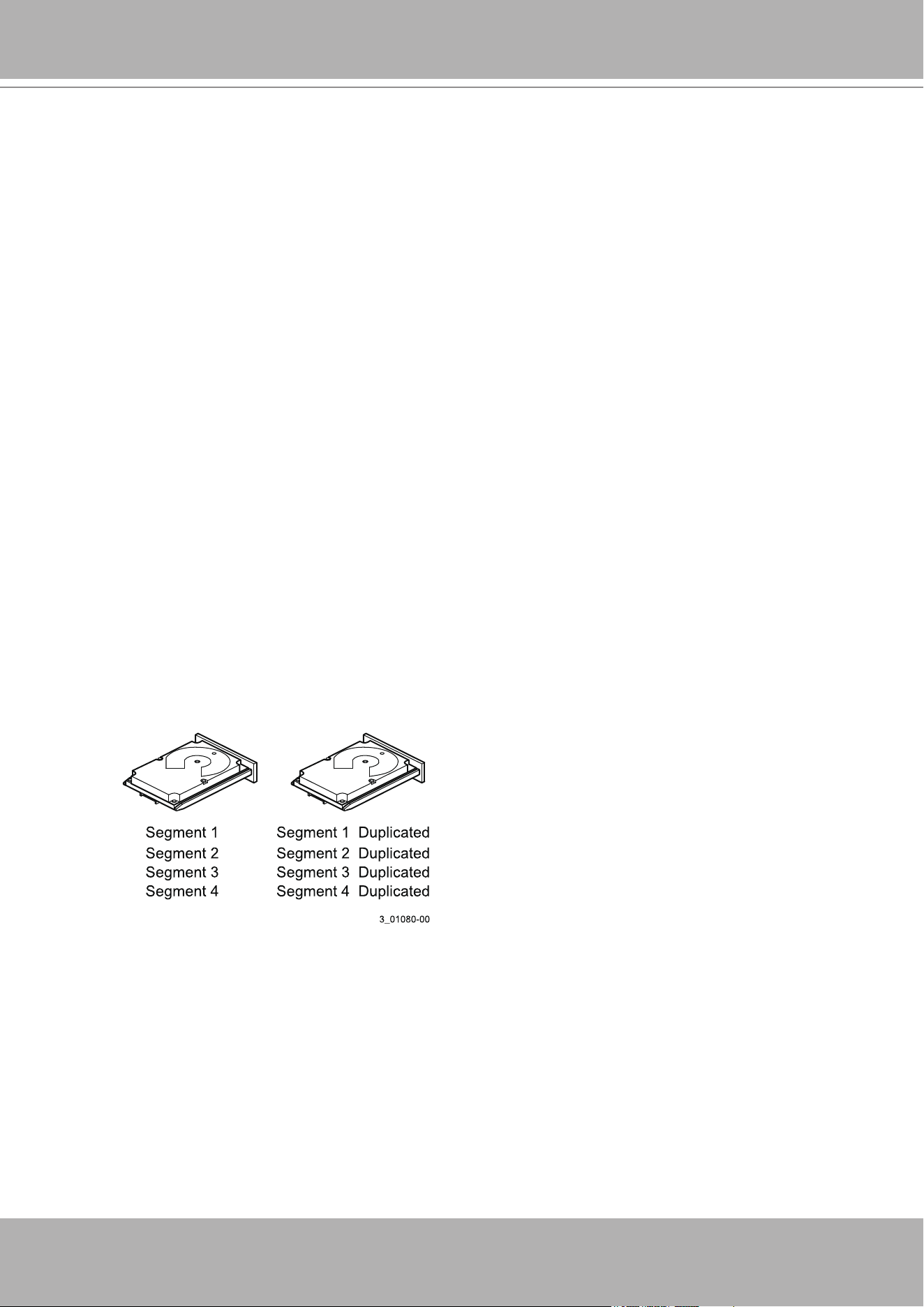
VIVOTEK - A Leading Provider of Multimedia Communication Solutions
48 - User's Manual
Disk Mirroring
With disk mirroring (used in RAID 1 and RAID 10), data written to one drive is simultaneously
written to another drive. The primary advantage of disk mirroring is that it provides 100 percent
data redundancy. Because the contents of the disk are completely written to a second disk, data
is not lost if one disk fails. In addition, both drives contain the same data at all times, so either
disk can act as the operational disk. If one disk fails, the contents of the other disk can run the
system and reconstruct the failed disk.
Disk mirroring provides 100 percent redundancy, but it is expensive because each drive in the
system must be duplicated. The following gure shows an example of disk mirroring.
Stripe Width
Stripe width is the number of drives involved in a drive group where striping is implemented. For
example, a four-disk drive group with disk striping has a stripe width of four.
Stripe Size
The stripe size is the length of the interleaved data segments that the RAID controller writes
across multiple drives, not including parity drives. For example, consider a stripe that contains
1 MB of drive space and has 64 KB of data residing on each drive in the stripe. In this case, the
stripe size is 1 MB and the strip size is 64 KB.
Strip Size
The strip size is the portion of a stripe that resides on a single drive.
Parity
Parity generates a set of redundancy data from two or more parent data sets. The redundancy
data can be used to reconstruct one of the parent data sets in the event of a drive failure. Parity
data does not fully duplicate the parent data sets, but parity generation can slow the write
process. In a RAID drive group, this method is applied to entire drives or stripes across all of the
drives in a drive group. The types of parity are described in the following table.
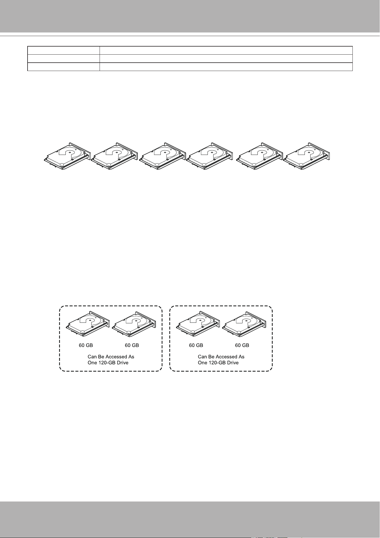
VIVOTEK - A Leading Provider of Multimedia Communication Solutions
User's Manual - 49
A RAID 5 drive group combines distributed parity with disk striping. If a single drive fails, it can
be rebuilt from the parity and the data on the remaining drives. An example of a RAID 5 drive
group is shown in the following gure. A RAID 5 drive group uses parity to provide redundancy
for one drive failure without duplicating the contents of entire drives. A RAID 6 drive group also
uses distributed parity and disk striping, but adds a second set of parity data so that it can
survive up to two drive failures.
Parity Type Description
Dedicated The parity data on two or more drives is stored on an additional disk.
Distributed The parity data is distributed across more than one drive in the system.
Segment 1
Segment 7
Segment 13
Segment 2
Segment 8
Segment 14
Segment 3
Segment 9
Segment 15
Segment 4
Segment 10
Parity (11 to 15)
Segment 5
Parity (6 to 10)
Segment 11
Parity (1 to 5)
Segment 6
Segment 12
Segment 19
Segment 25
Parity (26 to 30)
Segment 20
Parity (21 to 25)
Segment 26
Parity (16 to 20)
Segment 21
Segment 27
Segment 16
Segment 22
Segment 28
Segment 17
Segment 23
Segment 29
Segment 18
Segment 24
Segment 30
Disk Spanning
Disk spanning allows multiple drives to function like one big drive. Spanning overcomes lack
of disk space and simplies storage management by combining existing resources or adding
relatively inexpensive resources. For example, four 20-GB drives can be combined to appear
to the operating system as a single 80-GB drive.Spanning alone does not provide reliability or
performance enhancements. Spanned virtual drives must have the same stripe size and must
be contiguous. In the following gure, RAID 1 drive groups are turned into a RAID 10 drive
group.
Spanning two contiguous RAID 0 virtual drives does not produce a new RAID level or add
fault tolerance. It does increase the capacity of the virtual drive and improves performance by
doubling the number of spindles.
Spanning for RAID 00, RAID 10, RAID 50, and RAID 60 Drive Groups
The following table describes how to congure RAID 00, RAID 10, RAID 50, and RAID 60
drive groups by spanning. The virtual drives must have the same stripe size and the maximum
number of spans is 8. The full drive capacity is used when you span virtual drives; you cannot
specify a smaller drive capacity.

VIVOTEK - A Leading Provider of Multimedia Communication Solutions
50 - User's Manual
Level Description
00 Congure a RAID 00 by spanning two or more contiguous RAID 0 virtual drives, up to the
maximum number of supported devices for the controller.
10 Congure RAID 10 by spanning two or more contiguous RAID 1 virtual drives, up to
the maximum number of supported devices for the controller. A RAID 10 drive group
supports a maximum of 8 spans. You must use an even number of drives in each RAID
virtual drive in the span. The RAID 1 virtual drives must have the same stripe size.
50 Congure a RAID 50 drive group by spanning two or more contiguous RAID 5 virtual
drives. The RAID 5 virtual drives must have the same stripe size.
60 Congure a RAID 60 drive group by spanning two or more contiguous RAID 6 virtual
drives. The RAID 6 virtual drives must have the same stripe size.
Hot Spares
A hot spare is an extra, unused drive that is part of the disk subsystem. It is usually in Standby
mode, ready for service if a drive fails. Hot spares let you replace failed drives without system
shutdown or user intervention. The MegaRAID SAS RAID controllers can implement automatic
and transparent rebuilds of failed drives using hot spare drives, which provide a high degree of
fault tolerance and zero downtime.
The RAID management software lets you specify drives as hot spares. When a hot spare is
needed, the RAID controller assigns the hot spare that has a capacity closest to and at least as
great as that of the failed drive to take the place of the failed drive. The failed drive is removed
from the virtual drive and marked ready awaiting removal after the rebuild to a hot spare begins.
You can make hot spares of the drives that are not in a RAID virtual drive.
You can use the RAID management software to designate the hot spare to have enclosure
afnity, which means that if drive failures are present on a split backplane conguration, the hot
spare will be used rst on the backplane side in which it resides.If the hot spare is designated as
having enclosure afnity, it tries to rebuild any failed drives on the backplane in which it resides
before rebuilding any other drives on other backplanes.
The hot spare can be of two types:
• Global hot spare
• Dedicated hot spare
Global Hot Spare
Use a global hot spare drive to replace any failed drive in a redundant drive group as long as
its capacity is equal to or larger than the coerced capacity of the failed drive. A global hot spare
dened on any channel should be available to replace a failed drive on both channels.
Dedicated Hot Spare
Use a dedicated hot spare to replace a failed drive only in a selected drive group. One or more
drives can be designated as a member of a spare drive pool. The most suitable drive from the
pool is selected for failover. A dedicated hot spare is used before one from the global hot spare
pool.

VIVOTEK - A Leading Provider of Multimedia Communication Solutions
User's Manual - 51
Hot spare drives can be located on any RAID channel. Standby hot spares (not being used in
RAID drive group) are polled every 60 seconds at a minimum, and their status made available
in the drive group management software. RAID controllers offer the ability to rebuild with a disk
that is in a system but not initially set to be a hot spare.
Observe the following parameters when using hot spares:
• Hot spares are used only in drive groups with redundancy: RAID levels 1, 5, 6, 10, 50, and
60.
• A hot spare connected to a specic RAID controller can be used to rebuild a drive that is
connected only to the same controller.
• You must assign the hot spare to one or more drives through the controller BIOS or use drive
group management software to place it in the hot spare pool.
• A hot spare must have free space equal to or greater than the drive it replaces. For example,
to replace a 500-GB drive, the hot spare must be 500-GB or larger.
Disk Rebuilds
When a drive in a RAID drive group fails, you can rebuild the drive by re-creating the data that
was stored on the drive before it failed. The RAID controller re-creates the data using the data
stored on the other drives in the drive group. Rebuilding can be performed only in drive groups
with data redundancy, which includes RAID 1, 5, 6, 10, 50, and 60 drive groups.
The RAID controller uses hot spares to rebuild failed drives automatically and transparently,
at user-dened rebuild rates. If a hot spare is available, the Rebuild operation can start
automatically when a drive fails. If a hot spare is not available, the failed drive must be replaced
with a new drive so that the data on the failed drive can be rebuilt.
The failed drive is removed from the virtual drive and marked ready awaiting removal when the
Rebuild operation to a hot spare begins. If the system goes down during a Rebuild operation,
the RAID controller automatically resumes the rebuild after the system reboots.
NOTE
:
When the Rebuild operation to a hot spare begins, the failed drive is often removed from
the virtual drive before management applications detect the failed drive. When this removal
occurs, the event logs show the drive rebuilding to the hot spare without showing the failed
drive. The formerly failed drive will be marked as ready after a Rebuild operation begins to a
hot spare. If a source drive fails during a rebuild to a hot spare, the Rebuild operation fails,
and the failed source drive is marked as ofine. In addition, the rebuilding hot spare drive
is changed back to a hot spare. After a Rebuild operation fails because of a source drive
failure, the dedicated hot spare is still dedicated and assigned to the correct drive group, and
the global hot spare is still global.
An automatic drive Rebuild operation will not start if you replace a drive during a RAID-level
migration. The Rebuild operation must be started manually after the expansion or migration
procedure is complete. (RAID-level migration changes a virtual drive from one RAID level to
another.)
VIVOTEK - A Leading Provider of Multimedia Communication Solutions
52 - User's Manual
Hot Swap
A hot swap is the manual replacement of a defective drive unit while the computer is still
running. When a new drive has been installed, a Rebuild operation occurs automatically if these
situation occurs:
• The newly inserted drive is the same capacity as or larger than the failed drive.
• The newly inserted drive is placed in the same drive bay as the failed drive it is replacing.
The RAID controller can be congured to detect the new drives and rebuild the contents of the
drive automatically.
Parity Type Description
Online A drive that can be accessed by the RAID controller and is part of the virtual drive.
Uncongured Good A drive that is functioning normally but is not congured as a part of a virtual drive or as a
hot spare.
Hot Spare A drive that is powered up and ready for use as a spare in case an online drive fails.
Failed A drive that was originally congured as Online or Hot Spare, but on which the rmware
detects an unrecoverable error.
Rebuild A drive to which data is being written to restore full redundancy for a virtual drive.
Uncongured Bad A drive on which the rmware detects an unrecoverable error; the drive was Uncongured
Good or the drive could not be initialized.
Missing A drive that was Online but which has been removed from its location.
Ofine A drive that is part of a virtual drive but which has invalid data as far as the RAID
conguration is concerned.
Shield State An interim state of physical drive for diagnostic operations.
Copyback A drive that has replaced the failed drive in the RAID conguration.
Drive States
A drive state is a property indicating the status of the drive. The drive states are described in the
following table.
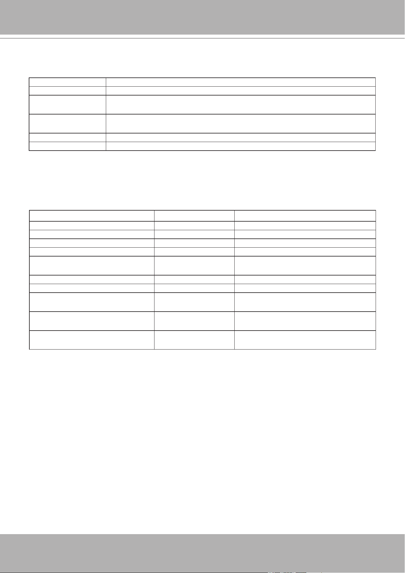
VIVOTEK - A Leading Provider of Multimedia Communication Solutions
User's Manual - 53
Parity Type Description
Online The virtual drive operating condition is good. All congured drives are online.
Degraded The virtual drive operating condition is not optimal. One of the congured drives has
failed or is ofine.
Partial Degraded The operating condition in a RAID 6 virtual drive is not optimal. One of the congured
drives has failed or is ofine. A RAID 6 drive group can tolerate up to two drive failures.
Failed The virtual drive has failed.
Ofine The virtual drive is not available to the RAID controller.
Virtual Drive States
The virtual drive states are described in the following table.
Parity Type Virtual Drive State Beep Code
RAID 0 virtual drive loses a virtual drive Ofine 3 seconds on and 1 second off
RAID 1 virtual drive loses a mirror drive Degraded 1 second on and 1 second off
RAID 1 virtual drive loses both drives Ofine 3 seconds on and 1 second off
RAID 5 virtual drive loses one drive Degraded 1 second on and 1 second off
RAID 5 virtual drive loses two or more
drives
Ofine 3 seconds on and 1 second off
RAID 6 virtual drive loses one drive Partially degraded 1 second on and 1 second off
RAID 6 virtual drive loses two drives Degraded 1 second on and 1 second off
RAID 6 virtual drive loses more than two
drives
Ofine 3 seconds on and 1 second off
A hot spare completes the Rebuild
process and is brought into a drive group
B/A 1 second on and 3 seconds off
A copy back occurs after a Rebuild
operation completes
Optimal 1 second on and 3 seconds off
Beep Codes
An alarm sounds on the MegaRAID controller when a virtual drive changes from an optimal
state to another state, when a hot spare rebuilds, and for test purposes.
RAID Levels
The RAID controller supports RAID levels 0, 00, 1, 5, 6, 10, 50, and 60. The supported RAID
levels are summarized in the following section.
In addition, the RAID controller supports independent drives (congured as RAID 0 and RAID 00
drive groups) The following sections describe the RAID levels in detail.
Summary of RAID Levels
A RAID 0 drive group uses striping to provide high data throughput, especially for large les in
an environment that does not require fault tolerance.
A RAID 1 drive group uses mirroring so that data written to one drive is simultaneously written
to another drive. The RAID 1 drive group is good for small databases or other applications that
require small capacity but complete data redundancy.

VIVOTEK - A Leading Provider of Multimedia Communication Solutions
54 - User's Manual
A RAID 5 drive group uses disk striping and parity data across all drives (distributed parity) to
provide high data throughput, especially for small random access.A RAID 6 drive group uses
distributed parity, with two independent parity blocks per stripe, and disk striping.
A RAID 6 virtual drive can survive the loss of any two drives without losing data. A RAID 6 drive
group, which requires a minimum of three drives, is similar to a RAID 5 drive group. Blocks of
data and parity information are written across all drives. The parity information is used to recover
the data if one or two drives fail in the drive group.
A RAID 00 drive group is a spanned drive group that creates a striped set from a series of
RAID 0 drive groups.A RAID 10 drive group, a combination of RAID 0 and RAID 1 drive groups,
consists of striped data across mirrored spans.
A RAID 10 drive group is a spanned drive group that creates a striped set from a series of
mirrored drives. A RAID 10 drive group allows a maximum of 8 spans. You must use an even
number of drives in each RAID virtual drive in the span. The RAID 1 virtual drives must have
the same stripe size. A RAID 10 drive group provides high data throughput and complete data
redundancy but uses a larger number of spans.
A RAID 50 drive group, a combination of RAID 0 and RAID 5 drive groups, uses distributed
parity and disk striping. A RAID 50 drive group is a spanned drive group in which data is striped
across multiple RAID 5 drive groups. A RAID 50 drive group works best with data that requires
high reliability, high request rates, high data transfers, and medium-to-large capacity.
NOTE
Having virtual drives of different RAID levels, such as RAID Level0 and RAID Level5, in the
same drive group is not allowed. For example, if an existing RAID5 virtual drive is created out
of partial space in an array, the next virtual drive in the array has to be RAID Level 5 only.
A RAID 60 drive group, a combination of RAID level 0 and RAID Level 6, uses distributed parity,
with two independent parity blocks per stripe in each RAID set, and disk striping. A RAID 60
virtual drive can survive the loss of two drives in each of the RAID 6 sets without losing data. A
RAID 60 drive group works best with data that requires high reliability, high request rates, high
data transfers, and medium-to-large capacity.
NOTE
The MegaSR controller supports the standard RAID levels – RAID0, RAID1, RAID5, and
RAID10. The MegaSR controller comes in two variants, SCU and AHCI, both supporting a
maximum of eight physical drives. A maximum of eight virtual drives can be created (using
RAID0, RAID 1, RAID5, and RAID10 only) and controlled by the MegaSR controller. One
virtual drive can be created on an array (a maximum of eight if no other virtual drives are
already created on the MegaSR controller), or you can create eight arrays with one virtual
drive each. However, on a RAID10 drive group, you can create only one virtual drive on a
particular array.
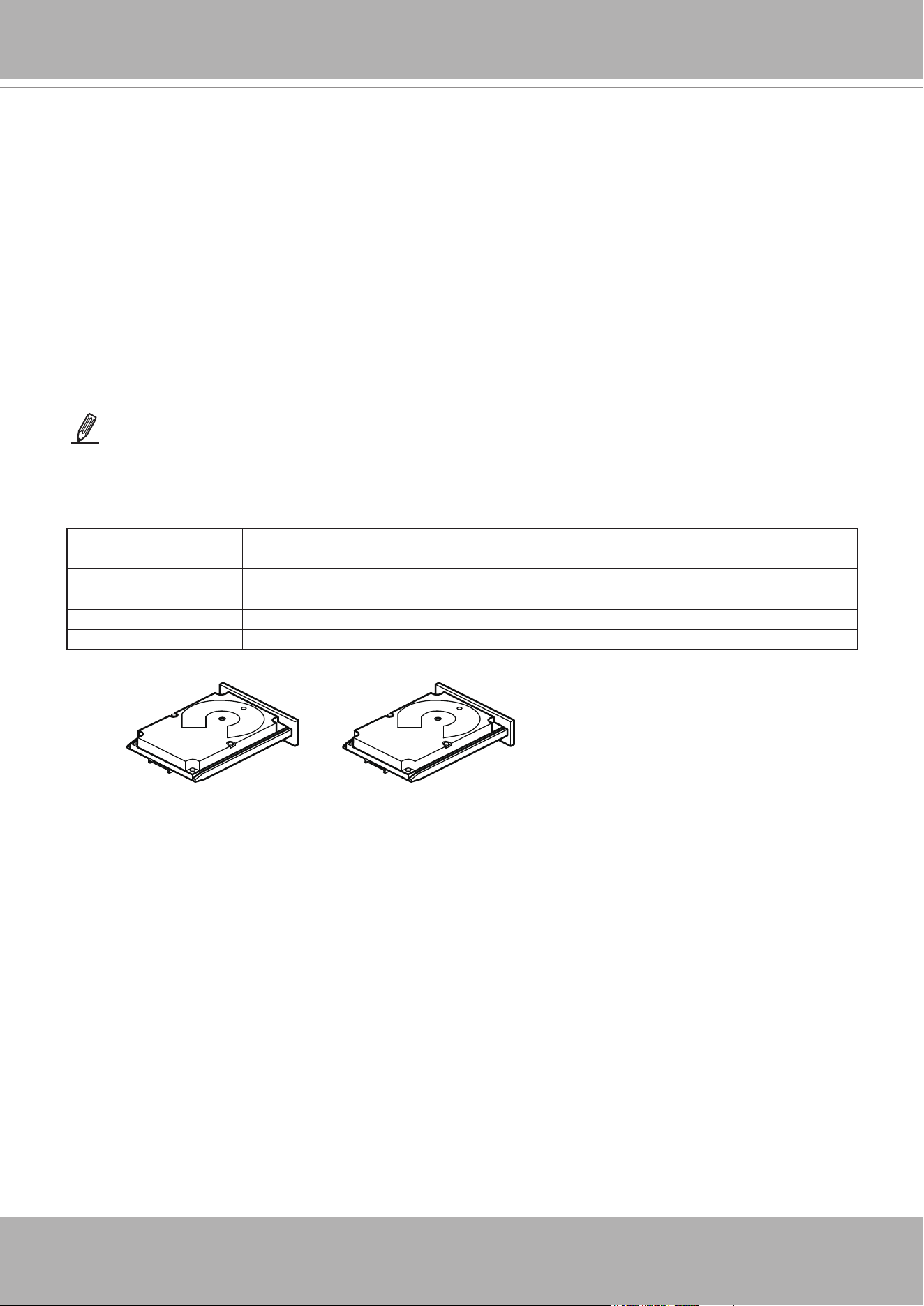
VIVOTEK - A Leading Provider of Multimedia Communication Solutions
User's Manual - 55
Uses Provides high data throughput, especially for large les.Any environment that does not
require fault tolerance.
Strong points Provides increased data throughput for large les.
No capacity loss penalty for parity.
Weak points Does not provide fault tolerance or high bandwidth.All data is lost if any drive fails.
Drives 1 to 32
RAID 0 Drive Groups
A RAID 0 drive group provides disk striping across all drives in the RAID drive group. A RAID0
drive group does not provide any data redundancy, but the RAID 0 drive group offers the best
performance of any RAID level. The RAID 0 drive group breaks up data into smaller segments,
and then stripes the data segments across each drive in the drive group. The size of each data
segment is determined by the stripe size. A RAID 0 drive group offers high bandwidth.
By breaking up a large le into smaller segments, the RAID controller can use both SAS
drives and SATA drives to read or write the le faster. A RAID 0 drive group involves no parity
calculations to complicate the write operation. This situation makes the RAID 0 drive group ideal
for applications that require high bandwidth but do not require fault tolerance. The following
table provides an overview of the RAID 0 drive group. The following gure provides a graphic
example of a RAID 0 drive group.
NOTE
RAID level 0 is not fault tolerant. If a drive in a RAID 0 drive group fails, the entire virtual drive (all drives
associated with the virtual drive) fails.
Segment 1
Segment 3
Segment 5
Segment 2
Segment 4
Segment 6
Segment 7 Segment 8
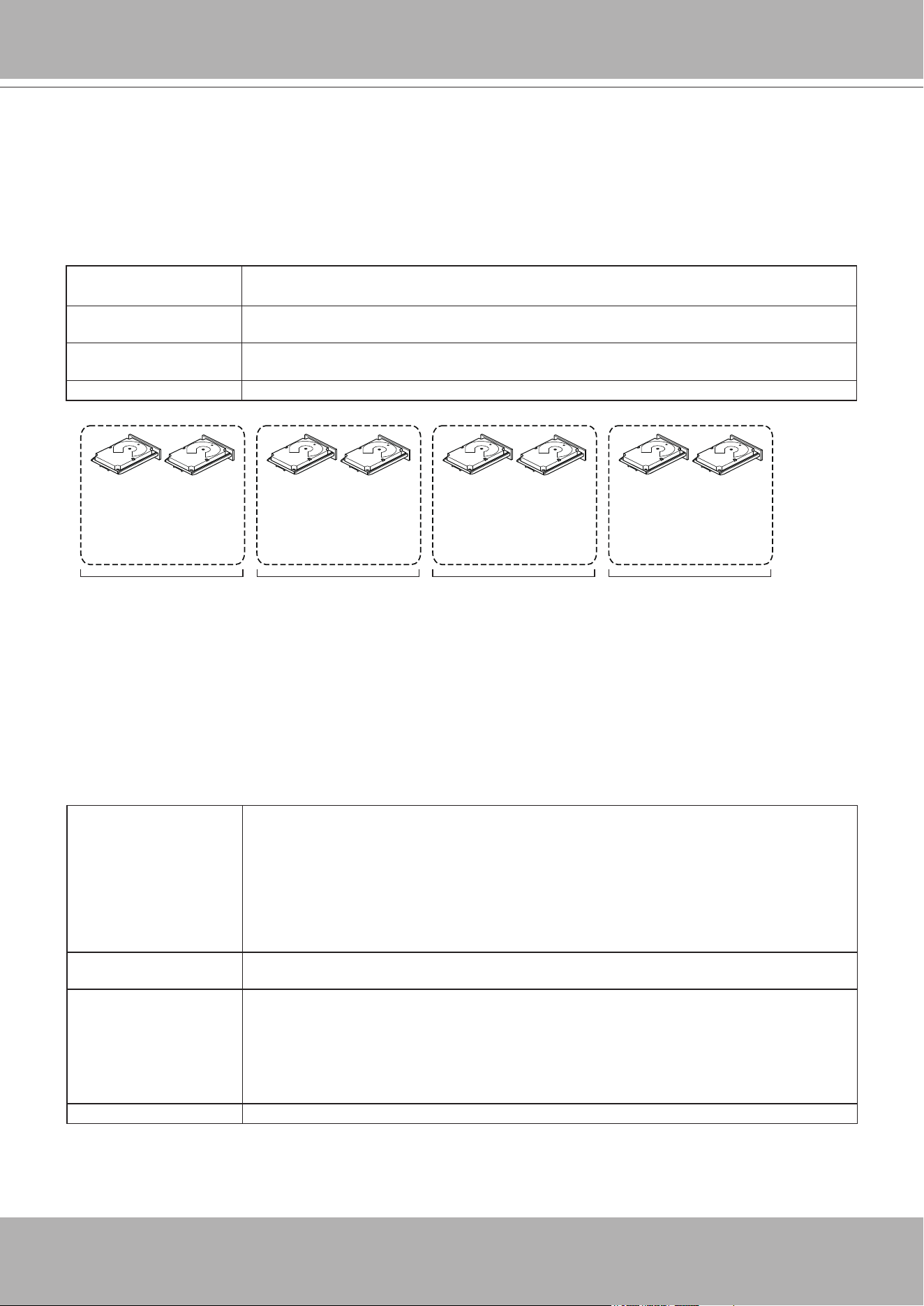
VIVOTEK - A Leading Provider of Multimedia Communication Solutions
56 - User's Manual
RAID 1 Drive Groups
In RAID 1 drive groups, the RAID controller duplicates all data from one drive to a second drive
in the drive group. A RAID 1 drive group supports an even number of drives from 2 through 32
in a single span. The RAID1 drive group provides complete data redundancy, but at the cost
of doubling the required data storage capacity. The following table provides an overview of a
RAID1 drive group. The following gure provides a graphic example of a RAID1 drive group.
Uses Use RAID 1 drive groups for small databases or any other environment that requires fault
tolerance but small capacity.
Strong points Provides complete data redundancy.A RAID 1 drive group is ideal for any application that
requires fault tolerance and minimal capacity.
Weak points Requires twice as many drives.
Performance is impaired during drive rebuilds.
Drives 2 through 32 (must be an even number of drives)
Segment 1
RAID 1
Segment 1
Duplicate
Segment 5 Segment 5
Duplicate
...
Segment 2 Segment 2
Duplicate
Segment 6 Segment 6
Duplicate
...
Segment 3
Segment 3
Duplicate
Segment 7 Segment 7
Duplicate
...
Segment 4 Segment 4
Duplicate
Segment 8 Segment 8
Duplicate
...
RAID 1 RAID 1 RAID 1
RAID 5 Drive Groups
A RAID 5 drive group includes disk striping at the block level and parity. Parity is the data’s
property of being odd or even, and parity checking is used to detect errors in the data. In RAID5
drive groups, the parity information is written to all drives. A RAID5 drive group is best suited for
networks that perform a lot of small input/output (I/O) transactions simultaneously.The following
table provides an overview of a RAID5 drive group. The following gure provides a graphic
example of a RAID5 drive group.
Uses Provides high data throughput, especially for large les.
Use RAID 5 drive groups for transaction processing applications because each drive can
read and write independently.
If a drive fails, the RAID controller uses the parity drive to re-create all missing
information.Use also for online customer service that requires fault tolerance.Use for any
application that has high read request rates but random write request rates.
Strong points Provides data redundancy, high read rates, and good performance in most environments.
Provides redundancy with lowest loss of capacity.
Weak points Not well suited to tasks requiring lots of small writes or small block write operations.
Suffers more impact if no cache is used.
Drive performance is reduced if a drive is being rebuilt.
Environments with few processes do not perform as well because the RAID drive group
overhead is not offset by the performance gains in handling simultaneous processes.
Drives 3 through 32
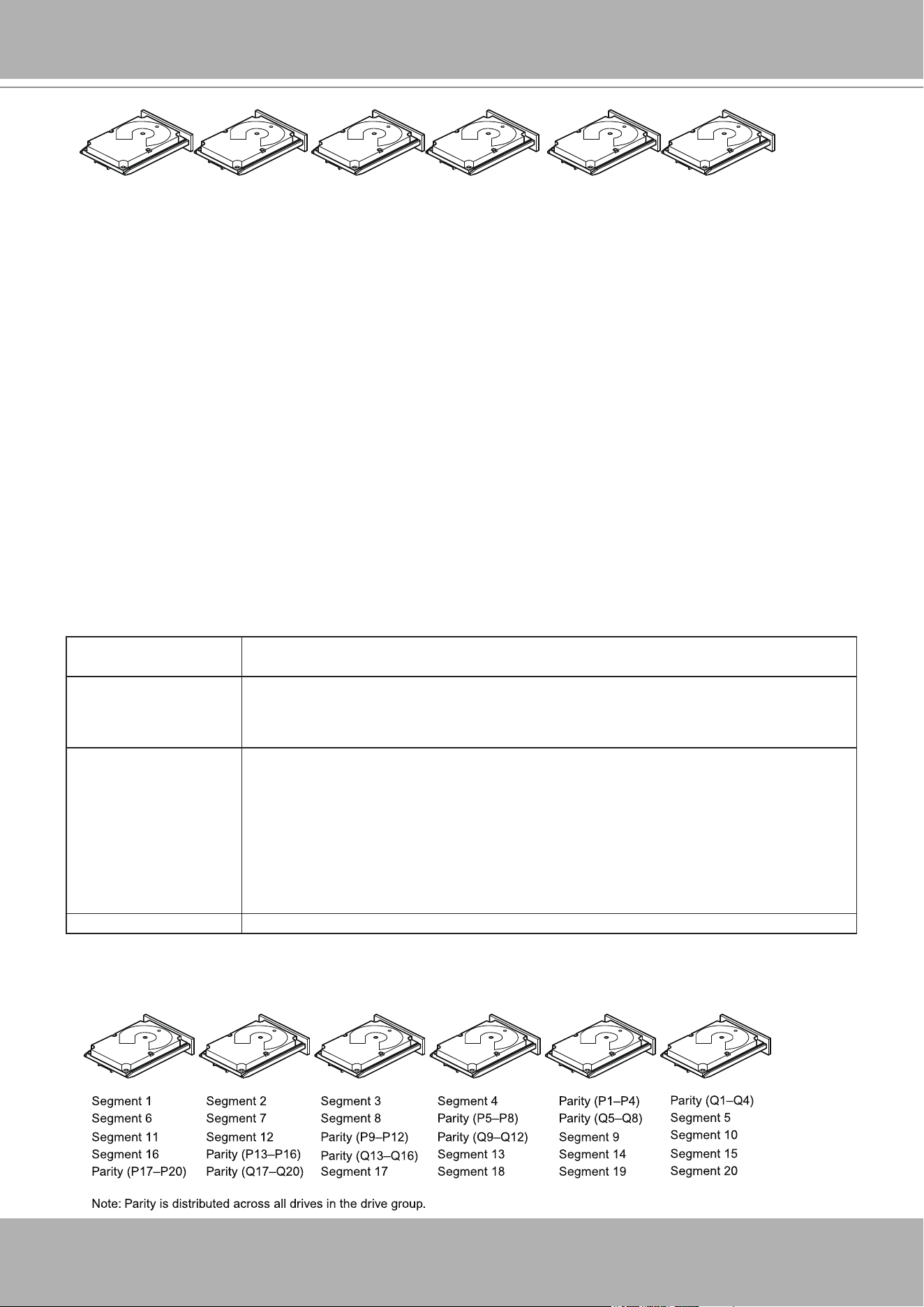
VIVOTEK - A Leading Provider of Multimedia Communication Solutions
User's Manual - 57
Segment 1
Segment 7
Segment 13
Segment 2
Segment 8
Segment 14
Segment 3
Segment 9
Segment 15
Segment 4
Segment 10
Parity (11 to 15)
Segment 5
Parity (6 to 10)
Segment 11
Parity (1 to 5)
Segment 6
Segment 12
Segment 19
Segment 25
Parity (26 to 30)
Segment 20
Parity (21 to 25)
Segment 26
Parity (16 to 20)
Segment 21
Segment 27
Segment 16
Segment 22
Segment 28
Segment 17
Segment 23
Segment 29
Segment 18
Segment 24
Segment 30
RAID 6 Drive Groups
A RAID6 drive group is similar to a RAID5 drive group (disk striping and parity), except that
instead of one parity block per stripe, there are two. With two independent parity blocks, A
RAID6 drive group can survive the loss of any two drives in a virtual drive without losing data.
A RAID6 drive group provides a high level of data protection through the use of a second
parity block in each stripe. Use a RAID6 drive group for data that requires a very high level of
protection from loss.
In the case of a failure of one drive or two drives in a virtual drive, the RAID controller uses the
parity blocks to re-create all of the missing information. If two drives in a RAID6 virtual drive fail,
two drive rebuilds are required, one for each drive. These rebuilds do not occur at the same
time. The controller rebuilds one failed drive, and then the other failed drive.The following table
provides an overview of a RAID6 drive group.
Uses Use for any application that has high read request rates but low random or small block
write rates.
Strong points Provides data redundancy, high read rates, and good performance in most environments.
Can survive the loss of two drives or the loss of a drive while another drive is being
rebuilt.Provides the highest level of protection against drive failures of all of the RAID
levels.Performance is similar to that of a RAID5 drive group.
Weak points Not well-suited to tasks requiring a lot of small and/or random write operations.A RAID 6
virtual drive must generate two sets of parity data for each write operation, which results
in a signicant decrease in performance during write operations.
Drive performance is reduced during a drive Rebuild operation.Environments with
few processes do not perform as well because the RAID overhead is not offset by the
performance gains in handling simultaneous processes.
A RAID6 drive group costs more because of the extra capacity required by using two
parity blocks per stripe.
Drives 3 through 32
The following gure shows a RAID6 drive group data layout. The second set of parity drives is
denoted by Q. The P drives follow the RAID5 drive group parity scheme.
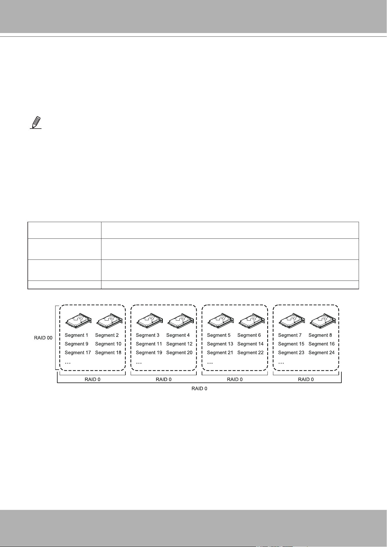
VIVOTEK - A Leading Provider of Multimedia Communication Solutions
58 - User's Manual
RAID 00 Drive Groups
A RAID 00 drive group is a spanned drive group that creates a striped set from a series of
RAID0 drive groups. A RAID00 drive group does not provide any data redundancy, but, along
with the RAID0 drive group, does offer the best performance of any RAID level. A RAID00 drive
group breaks up data into smaller segments and then stripes the data segments across each
drive in the drive groups. The size of each data segment is determined by the stripe size. A
RAID00 drive group offers high bandwidth.
Uses Provides high data throughput, especially for large les.Any environment that does not
require fault tolerance.
Strong points Provides increased data throughput for large les.
No capacity loss penalty for parity.
Weak points Does not provide fault tolerance or high bandwidth.
All data lost if any drive fails.
Drives 2 through 256
NOTE
RAID level 00 is not fault tolerant. If a drive in a RAID 0 drive group fails, the entire virtual drive (all drives
associated with the virtual drive) fails.
By breaking up a large le into smaller segments, the controller can use both SAS drives and
SATA drives to read or write the le faster. A RAID00 drive group involves no parity calculations
to complicate the write operation. This situation makes the RAID00 drive group ideal for
applications that require high bandwidth but do not require fault tolerance. The following table
provides an overview of the RAID00 drive group. The following gure provides a graphic
example of a RAID 00 drive group.
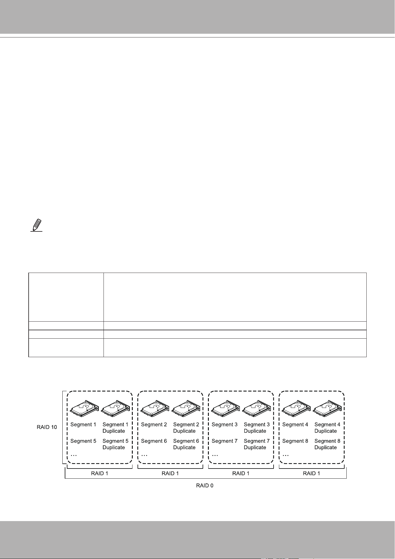
VIVOTEK - A Leading Provider of Multimedia Communication Solutions
User's Manual - 59
RAID 10
A RAID10 drive group is a combination of RAID level 0 and RAID level 1, and it consists of
stripes across mirrored drives. A RAID10 drive group breaks up data into smaller blocks and
then mirrors the blocks of data to each RAID1 drive group. The rst RAID1 drive in each drive
group then duplicates its data to the second drive. The size of each block is determined by the
stripe size parameter, which is set during the creation of the RAID set. The RAID 1 virtual drives
must have the same stripe size.
Spanning is used because one virtual drive is dened across more than one drive group. Virtual
drives dened across multiple RAIDlevel 1 drive groups are referred to as RAID level 10, (1+0).
Data is striped across drive groups to increase performance by enabling access to multiple drive
groups simultaneously.
Each spanned RAID 10 virtual drive can tolerate multiple drive failures, as long as each failure
is in a separate drive group. If drive failures occur, less than total drive capacity is available.
Congure RAID 10 drive groups by spanning two contiguous RAID1 virtual drives, up to the
maximum number of supported devices for the controller. A RAID10 drive group supports a
maximum of 8spans, with a maximum of 32drives per span. You must use an even number of
drives in each RAID10 virtual drive in the span.
Uses Appropriate when used with data storage that needs 100 percent redundancy of mirrored
drive groups and that also needs the enhanced I/O performance of RAID 0 (striped drive
groups.)
A RAID10 drive group works well for medium-sized databases or any environment that
requires a higher degree of fault tolerance and moderate-to-medium capacity.
Strong points Provides both high data transfer rates and complete data redundancy.
Weak points Requires twice as many drives as all other RAID levels except in RAID 1 drive groups.
Drives 4 to 32 in multiples of 4 — The maximum number of drives supported by the controller
(using an even number of drives in each RAID 10 virtual drive in the span).
NOTE
Other factors, such as the type of controller, can restrict the number of drives supported by RAID 10 virtual drives.
The following table provides an overview of a RAID10 drive group.
In the following gure, virtual drive 0 is created by distributing data across four drive groups (drive groups 0
through3).

VIVOTEK - A Leading Provider of Multimedia Communication Solutions
60 - User's Manual
RAID 50
A RAID50 drive group provides the features of both RAID0 and RAID5 drive groups. A RAID50
drive group includes both distributed parity and drive striping across multiple drive groups. A
RAID50 drive group is best implemented on two RAID5 drive groups with data striped across
both drive groups.
A RAID50 drive group breaks up data into smaller blocks and then stripes the blocks of data to
each RAID5 disk set. A RAID5 drive group breaks up data into smaller blocks, calculates parity
by performing an exclusive OR operation on the blocks, and then performs write operations
to the blocks of data and parity to each drive in the drive group. The size of each block is
determined by the stripe size parameter, which is set during the creation of the RAID set.
A RAID level 50 drive group can support up to eight spans and tolerate up to eight drive failures,
though less than total drive capacity is available. Though multiple drive failures can be tolerated,
only one drive failure can be tolerated in each RAID 5 level drive group.
The following table provides an overview of a RAID50 drive group.
Uses Appropriate when used with data that requires high reliability, high request rates, high
data transfer, and medium-to-large capacity.
Also used when a virtual drive of greater than 32 drives is needed.
Strong points Provides high data throughput, data redundancy, and very good performance.
Weak points Requires two times to eight times as many parity drives as a RAID 5 drive group.
Drives Eight spans of RAID 5 drive groups that contain 3 to 32 drives each (limited by the
maximum number of devices supported by the controller)
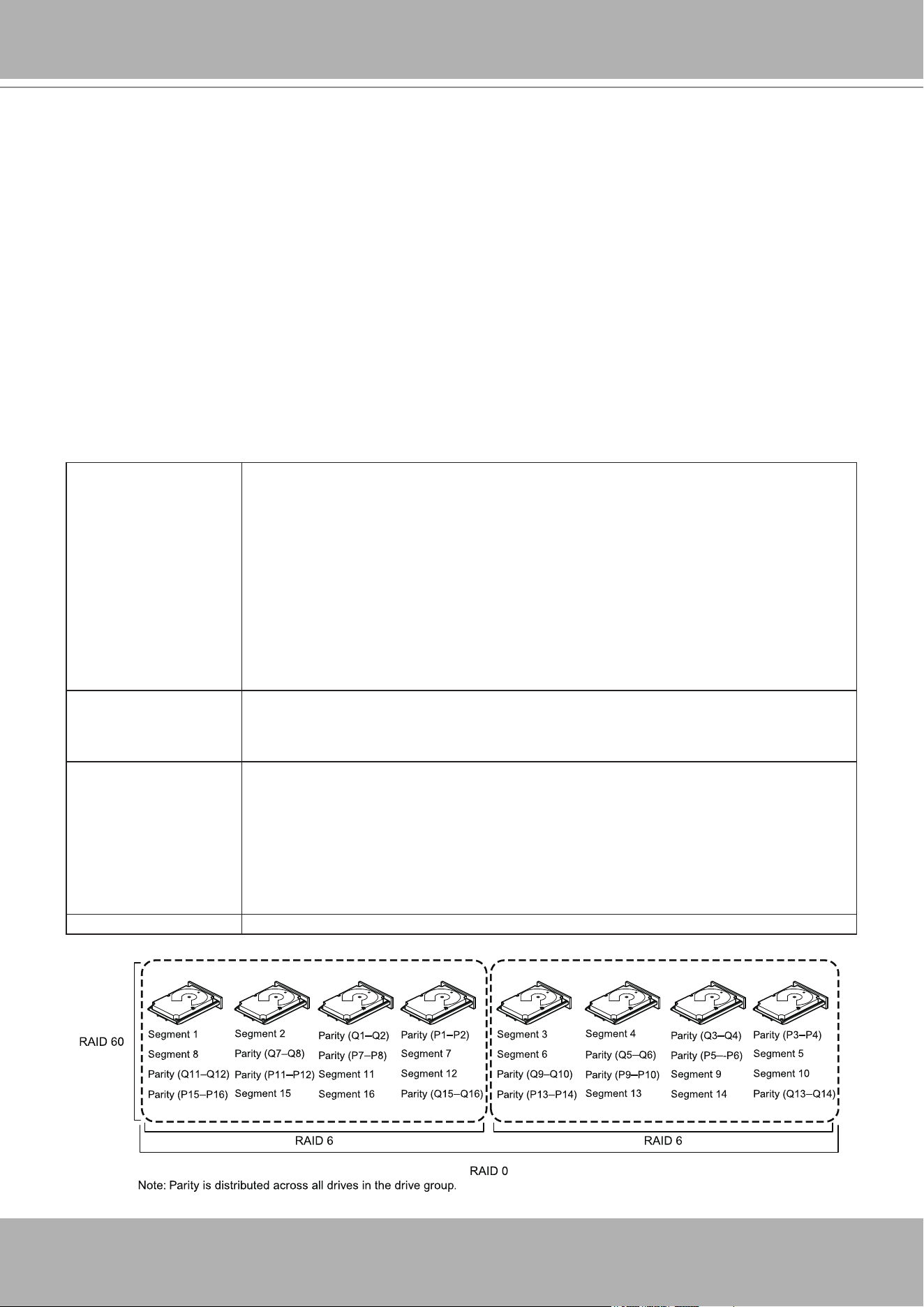
VIVOTEK - A Leading Provider of Multimedia Communication Solutions
User's Manual - 61
RAID 60
A RAID 60 drive group provides the features of both RAID 0 and RAID 6 drive groups, and
includes both parity and disk striping across multiple drive groups. A RAID6 drive group supports
two independent parity blocks per stripe. A RAID 60 virtual drive can survive the loss of two
drives in each of the RAID6 drive group sets without losing data. A RAID60 drive group is best
implemented on two RAID6 drive groups with data striped across both drive groups.
A RAID60 drive group breaks up data into smaller blocks and then stripes the blocks of data to
each RAID6 disk set. A RAID6 drive group breaks up data into smaller blocks, calculates parity
by performing an exclusive-OR operation on the blocks, and then performs write operations to
the blocks of data and writes the parity to each drive in the drive group. The size of each block is
determined by the stripe size parameter, which is set during the creation of the RAID set.
A RAID60 drive group can support up to 8spans and tolerate up to 16 drive failures, though less
than total drive capacity is available. Two drive failures can be tolerated in each RAID 6 level
drive group.
Uses Provides a high level of data protection through the use of a second parity block in each
stripe. Use a RAID60 drive group for data that requires a very high level of protection
from loss.
In the case of a failure of one drive or two drives in a RAID set in a virtual drive, the RAID
controller uses the parity blocks to re-create all of the missing information. If two drives in
a RAID 6 set in a RAID60 virtual drive fail, two drive Rebuild operations are required, one
for each drive. These Rebuild operations can occur at the same time.
Use for online customer service that requires fault tolerance. Use for any application that
has high read request rates but low write request rates. Also used when a virtual drive of
greater than 32 drives is needed.
Strong points Provides data redundancy, high read rates, and good performance in most environments.
Each RAID6 set can survive the loss of two drives or the loss of a drive while another
drive is being rebuilt.Provides the highest level of protection against drive failures of all of
the RAID levels.
Weak points Not well-suited for small block write or random write operations. A RAID 60 virtual
drive must generate two sets of parity data for each write operation, which results in
a signicant decrease in performance during write operations.Drive performance is
reduced during a drive Rebuild operation. Environments with few processes do not
perform as well because the RAID overhead is not offset by the performance gains in
handling simultaneous processes.
A RAID6 drive group costs more because of the extra capacity required by using two
parity blocks per stripe.
Drives A minimum of 6.
VIVOTEK - A Leading Provider of Multimedia Communication Solutions
62 - User's Manual
Technical Specications
Model NR9681
System
OS Embedded Windows
CPU Intel Core i5
Flash 64G SATA DOM
RAM 8GB
Watchdog Hardware + Software
Power Restoration System Restart Automatically after Power Recovery
Storage
HDD Devices Hot-Swappable Tray x8
HDD Max. Capacity 6TB x8
Disk Management
Create, Format and Remove Disk
RAID 0, 1, 5, 6, 10
Video & Audio
Video Output HDMI x1, Display Port x1, VGA x1, DVI x1
Resolution
HDMI: 4096x2304
DP: 3200x2000
VGA/DVI: 1920x1200
Graphics Decoder Hardware decoding
Decoding Capacity
H.265/H.264:
2560x1920 @ 30 fps (2-CH)
1920x1080 @ 120 fps (8-CH)
1280x720 @ 240 fps (16-CH)
1280x720 @ 480 fps (32-CH)
1280x720 @ 480 fps (64-CH)
Camera Position Change the viewcell position on the Live View screens
External Interface
USB Interface
USB 2.0 x4
USB 3.0 x2
Audio
Microphone audio jack Input x1
3.5 Line input audio jack x1
3.5 Line output audio jack x1
Network
Record
Maximum Channel 64
Record Throughput (MB) 512 Mbps
Network Throughput (MB) 400 Mbps
Audio Format G.711, G.726, AMR, AAC
Video Format MJPEG, MPEG4, H.264 AVC, H.264 SVC, H.265
Video Resolution VGA, 1MP, 2MP, 3MP, 5MP & 9MP Camera
Recording Time (sec.)
Pre-Record: 3 ~ 15
Post-Record: 10 ~ 60
Recording Stream Single
Recording Mode
Continuous, Schedule, Manual, Event, Activity Adaptive
Streaming
Recording Setting Recycle (unit: Size or Day)
Recording Path Local Path or Network Path
Record Video Format 3GP
LiveView (Local Display)
Stream Application Stream Selection & Auto Stream Size
LiveView Display
64-Channel (with Dual Monitors)
Multi Layout Display: 1x1, 2x2, 1+5, 3x3, 1+12, 4x4, 5x5, 1+31,
1P+2, 1P+6, 1P+8, 2V, 3V, 4V, 2V+3
Single Layout Display, Full Screen Display, Sequential Display
Monitor Enhancement
Drag & Drop, Remote I/O Control, PiP (Digital Zoom), Instant
Replay, De-interlace, Video Display Mode (Aspect Ratio, Hide
Borders, Keep Top/Down Borders), Fisheye Dewarp (Regular: 1O,
1P, 1R, 1O3R, 4R; Wall Mount: 1P2R, 1P3R; Ceiling/Floor Mount:
2P, 4R Pro, 1O8R), Video Enhancement (Basic Mode: Brightness,
Contrast, Saturation, Hue; Intelligent Mode: Defog, Rain, Snow,
Fire / Smoke)
PTZ Control Panel Control & Mouse Click Control
PTZ Operation
Direction Control, Home, Zoom, Focus, Iris, Preset, Patrol
(Group), Pan, Stop, Speed
Playback (Local Display)
Playback Display
16 Channels
Multi Layout Display: Multi Layout Display: 1x1, 2x2, 1+5, 3x3,
1+12, 4x4, 2V, 3V, 4V, 2V+3
Single Layout Display, Full Screen Display, Sequential Display
Playback Control
Play, Rewind, Pause, Stop, Next/Previous Video Start, Next/
Previous Frame, 1/8X ~ 64X Speed Control, Bookmark
Video Search
Browsing, Date & Time (Fast), Event, Bookmark, Alarm, Log,
Timeline, Timeline Scale
Monitor Enhancement
Drag & Drop, PiP (Digital Zoom), De-interlace, Video Display
Mode (Aspect Ratio, Hide Borders, Keep Top/Down Borders),
Fisheye Dewarp (Regular: 1O, 1P, 1R, 1O3R, 4R; Wall Mount:
1P2R, 1P3R; Ceiling/Floor Mount: 2P, 4R Pro, 1O8R), Video
Enhancement (Basic Mode: Brightness, Contrast, Saturation,
Hue; Intelligent Mode: Defog, Rain, Snow, Fire/Smoke)
Snapshot JPEG & BMP
Video Clip Export AVI, 3GP & EXE
LiveView (Remote)
LiveView Display
32 Channels
Multi Layout display: 1x1, 2x2, 3x3, 4x4, 5x5, 1+5, 1+12, 1+31
Monitor Enhancement
Drag & Drop, Image Freeze, Audio Control, Remote I/O Control,
Event Notification, Bookmark, Fisheye Dewarp (1O, 1P, 1R)
PTZ Control Panel Control
PTZ Operation Direction Control, Home, Zoom, Preset
Snapshot JPEG
Playback (Remote)
Playback Display
1 Channel
Multi Layout display: 1x1
Playback Control
Regular (Play, Pause, Stop), Speed Control, Timeline, Timeline
Scale
Monitor Enhancement
Drag & Drop, Audio Control, PiP Control, Fisheye Dewarp (1O,
1P, 1R)
Snapshot JPEG
Alarm Management
Schedule Type Continuous, Schedule, Manual
Hardware Information
Software Information
Network Interface 10/100/1000Mbps Ethernet (RJ-45) x2
Protocols
IPv4,TCP/IP, HTTP, HTTPS, UPnP, RTSP/RTP/RTCP, SMTP, FTP,
DHCP, NTP, DNS, DDNS, IP Filter
Power
Power Input Redundant Power 100~220V AC
Power Consumption Max. 740 W
LED Indicator
LED Indicator Power, HDD, Net1, Net2, Overheat, Power fail
Mechanic
Form Factor 2U Rackmount
Operation Buttons Power, Reset
Dimensions 89 (H) x 437 (W) x 648 (D) mm
Weight 27 kg (without HDD)
Operating Temperature 5°C ~ 35°C (41°F ~ 95°F)
Humidity 0 ~ 95%
General
Safety Certifications CE, LVD, FCC, VCCI, C-Tick, UL
Warranty 36 months
Client PC Requirements
Operating System
Microsoft Windows 8, 7, Vista, XP
Microsoft Windows Server 2012, 2008, 2003, 2000
CPU Intel Celeron or above
Memory 2 GB or above
Ethenet 10/100Mbps
Display Resolution 1024x768 pixels or above
Web Browser Internet Explorer 11/10/9 (32 bit)
Software AP Installation Wizard 2, Shepherd, VAST
Mobile/Tablet App iViewer (iOS/Android)
Accessories
Others
Power Cord, Quick Installation Guide, 8x H.D.D. Tray, 1x USB
Mouse
Camera Event
Motion, DI/O, Video Lost/Restore, PIR, Tampering, Temperature,
IR, Line Crossing Detection, Loitering Detection, Field Detection
Camera Status Connection Status, Recording Status, Recording Error
Substation Substation Connection Status
Storage Status Storage Connection Status, Storage Capacity Status
Station Status License Status, Network Status, Virtual Memory Status
Action
Email, Start Recording, Set DO, GSM Short Message, HTTP &
Client Notification
Recording Time (sec.) Max. 30
Backup
Manual
USB Dongle (FAT Format)
NAS (SMB & CIFS)
System
User Management
Authentication: Basic Account / Windows AD Account
User Account: 1024
User Account Time Limit: No limitation
User Level: Administrator / Power User / User / Operation /
Guest
Log Operation, System and Event Log
Date&Time Sync Server
Firmware Manual update
Restore Default Supported
Backup/Restore (Configuration) Supported
Language
Czech, English, French, German, Italian, Japanese, Persian,
Portuguese, Russian, Spanish, Simplified Chinese, Traditional
Chinese
Camera Intergration
Insert Camera Manual, Search
Video (Media) Setting Compression, Resolution, FPS, Video Quality
Audio Setting Codec, Bitrate
PTZ Control Panel Control & Mouse Click Control
PTZ Operation
Direction Control, Home, Zoom, Focus, Iris, Preset, Patrol
(Group), Pan, Stop, Speed
Motion Detection Supported
ONVIF Core Spec Version 2.2 or above (By Project)
ONVIF Stream Video (H.264, MPEG4 & MJPEG) & Audio (G.711, One Way)
ONVIF Recording Continuous, Schedule, Manual
ONVIF Control PTZ Control (Up, Down, Left, Right & Zoom In/Out)
ONVIF Discover
Discover the other brand camera through
"Insert Camera & Batch Insert"
Device Intergration
UPS Windows UPS Compatible
Joystick
VIVOTEK USB Joystick
All Windows® Compatible USB Joystick
I/O Box Advantech ADAM-6000
Switch VIVOTEK VivoCam PoE Switch (AW-GEV Series)
Dimensions
89 mm
437 mm
648 mm
All specifications are subject to change without notice. Copyright © VIVOTEK INC. All rights reserved. Ver. 6
6F, No.192, Lien-Cheng Rd., Chung-Ho, New Taipei City, 235, Taiwan, R.O.C. T: +886-2-82455282 F: +886-2-82455532 E: sales@vivotek.com W: www.vivotek.com
VIVOTEK INC.
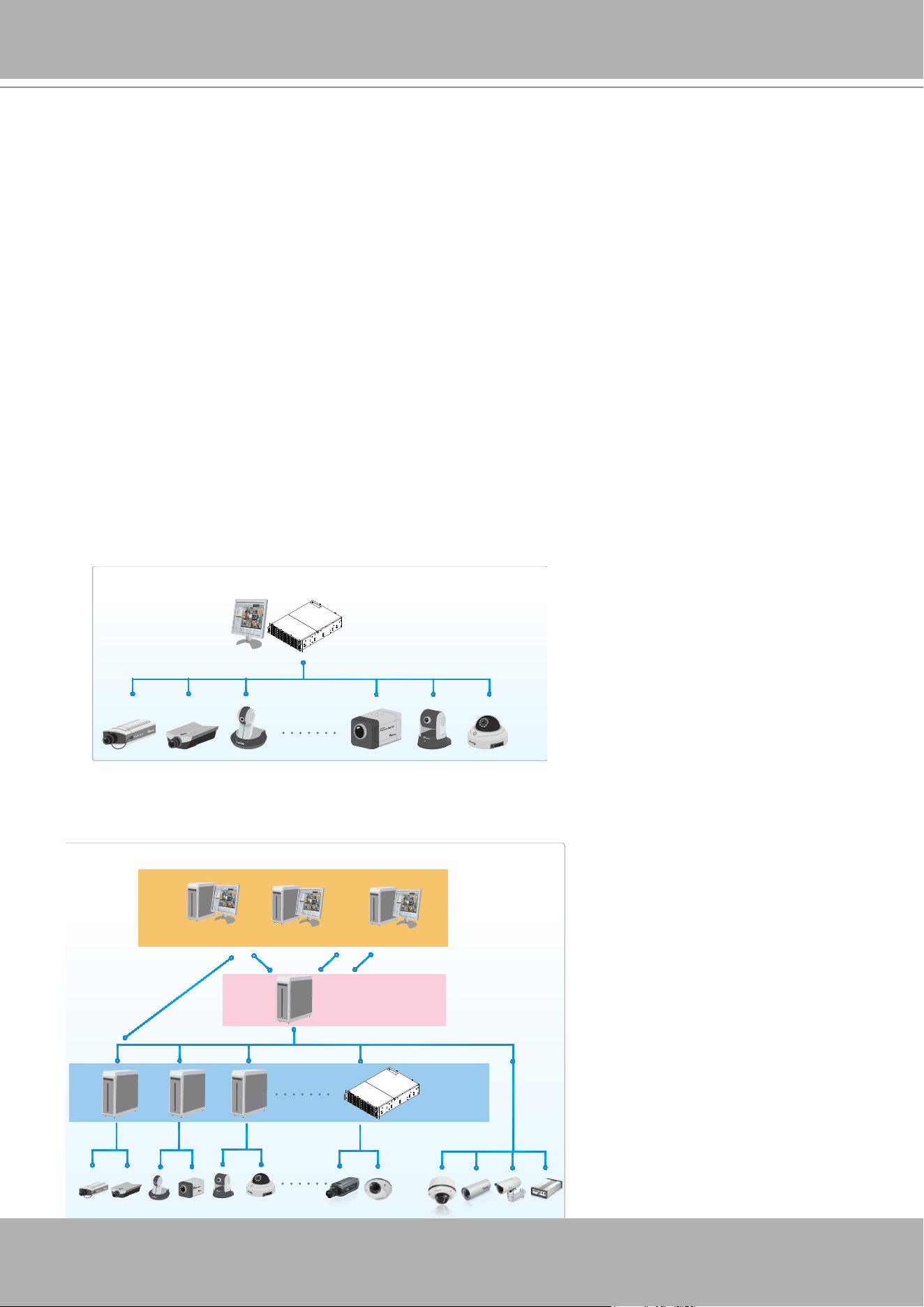
VIVOTEK - A Leading Provider of Multimedia Communication Solutions
User's Manual - 63
VAST Server and Client Components
There are four components in VAST: one server component--VAST Server, three client
components--
VAST LiveClient, VAST Playback
, and
VAST Matrix
.
VAST Server
provides a centralized management site for video recording.
VAST LiveClient
is a client program for the user to login and modify the server's conguration, edit the server's
recording storage, schedules and many other functions on the server;
VAST Playback
is
another client program for the user to log in and browse the recorded video database and video
clips related to specic events on the server.
Usage Scenario
The powerful management scalability of VAST makes it suitable for managing small- to large-
scale structures.
For users that manage only a few cameras, we recommend installing the client and server
components on the same computer. A host with all of the three components installed is recognized
as a stand-alone site. All the functions can be simultaneously performed on one single site.
For users who manage large-scale surveillance deployments, please plan the hierarchical
structure rst. Then you can start to add cameras to each station and connect these sub-stations
to the root station. The whole hierarchical management system is thus constructed.
Router
VAST LiveClient
VAST Server
Network Cameras
VAST Playback
Stand-alone site
Local Server Structure
Unlimited No. of Network Cameras , Video Servers...
Remote Server Structure
Router
Login
Login
VAST LiveClient
VAST Playback
Client
(Root station)
VAST CMS Server
NVR
Web Console
Please refer to page 267 for
Logical Tree configuration, which
allows for a flexible and use-
oriented privilege control.

VIVOTEK - A Leading Provider of Multimedia Communication Solutions
64 - User's Manual
Technical Specications
Technical Specifications
Version 1.13
General
Max. Number of
Cameras*
Unlimited
Max. Number of Servers* Unlimited
Max. Number of Clients Unlimited
Support OS
Windows 10, 8, 7, Vista, XP
Windows Server 2012, 2008, 2003, 2000
Support Web Browser Internet Explorer 11/10/9
Mobile Support iViewer (iOS/Android)
Virtual Matrix Support* VAST Matrix
Devices Pack .vdp File Update
*Please refer to System Requirements Page
(http://www.vivotek.com/vast/#system)
LiveView (Local Display)
Max. Channel 128-Channel (with Dual Monitors)
Layout
Multi Layout Display: 1x1, 2x2, 1+5, 3x3,
1+12, 4x4, 5x5, 1+31, 8x8, 1P+2, 1P+6,
1P+8, 2V, 3V, 4V, 2V+3
Single Layout Display, Full Screen Display,
Sequential Display, Layout Rotate
Stream Application Stream Selection & Auto Stream Size
View Application
Drag & Drop
Remote I/O Control
PiP (Digital Zoom)
Instant Replay
De-interlace
Video Display Mode (Aspect Ratio, Hide
Borders, Keep Top/Down Borders)
Fisheye Dewarp Mode
Fisheye Display Mode:
Regular: 1O, 1P, 1R, 1O3R, 4R
Wall Mount: 1P2R, 1P3R
Ceiling/Floor Mount: 2P, 4R Pro, 1O8R
Playback
Max. Channel 16 Channels
Layout
Multi Layout Display: 1x1, 2x2, 1+5, 3x3,
1+12, 4x4, 2V, 3V, 4V, 2V+3
Single Layout Display, Full Screen Display,
Sequential Display
Playback Mode Asynchronous & Synchronous
Playback Control
Play, Rewind, Pause, Stop, Next/Previous
Video Start, Next/Previous Frame, 1/8X ~
64X Speed Control, Bookmark
Search Mode
Browsing, Date & Time (Fast), Event,
Bookmark, Alarm, Log, Timeline, Timeline
Scale
Video
Video Format
MJPEG, MPEG4, H.264 AVC, H.264 SVC,
H.265
Video Resolution Up to 9 Megapixels
Video Enhancement
Basic Mode: Brightness, Contrast,
Saturation, Hue
Intelligent Mode: Defog, Rain, Snow, Fire/
Smoke
Audio
Audio Format G.711, G.726, AMR, AAC
Audio Capability Two-way Audio
Audio Control Mute, Broadcasting & Sound Play
Record
Recording Time (sec.) Pre-Record: 3-15, Post-Record: 10-60
Recording Stream Type Unicast
Recording Stream Single/Multiple
Recording Mode
Continuous, Schedule, Manual, Event,
Activity Adaptive Streaming
Recording Setting Recycle (Unit: Size or Day)
Recording File Format 3GP
External Storage
Recording
NAS (SMB & CIFS)
Alarm Management
Alarm Period (sec.) Max. 30
Alarm Filter Name, Time, Source, Event Type, State
Alarm Setting
LiveView Alarm Notification: Fixed &
Popup
Alert Sound
Schedule Type Continuous, Schedule, Manual
Camera Event
Motion, DI/O, Video Lost/Restore, PIR,
Tampering, Temperature, IR, PPTZ, Line
Crossing Detection, Loitering Detection,
Field Detection, Audio detection, SD
Card life Expectancy Detection, Shock
Detection, ONVIF Motion Event, ONVIF DI/
O, ONVIF Video Lost/Restore
Camera Status
Connection Status, Recording Status,
Recording Error
Substation
Substation Connection Status, Substation
DI/DO Trigger*
* Support for VIVOTEK's ND Series NVR
Storage Status
Storage Connection Status, Storage
Capacity Status
Station Status
License Status, Network Status, Virtual
Memory Status
External Devices Event DI/O (With I/O Box)
Action
Email, Start Recording, Move to preset
location, Set DO, GSM Short Message,
HTTP & Client notification
Alarm State for
Management
New, Assigned, In Progress, Resolved,
Closed, Later, Reject, Ignore
Alarm Result Export .csv File
eMap
Source Import Picture
Device
Camera, External DI/O, Substation
camera, Substation DI/DO*
* Support for VIVOTEK's ND Series NVR
Marked
Add, Remove, Direction Control, PTZ
Control & Indicator LiveView
Event Notification
Event Icon Light Flash, Show Live
Streaming on E-map
PTZ
PTZ/ePTZ Control Panel Control & Mouse Click Control
PTZ/ePTZ Operation
Direction Control, Home, Zoom, Focus,
Iris, Preset, Patrol (Group), Pan, Stop,
Speed

VIVOTEK - A Leading Provider of Multimedia Communication Solutions
User's Manual - 65
All specifications are subject to change without notice. Copyright © VIVOTEK INC. All rights reserved. Ver. 34
6F, No.192, Lien-Cheng Rd., Chung-Ho, New Taipei City, 235, Taiwan, R.O.C. | T: +886-2-82455282 | F: +886-2-82455532 | E: sales@vivotek.com | W: www.vivotek.com
Technical Specifications
PTZ Operation Mode Click to Move & Continuous Move
Export
Print Selection Windows & All Windows
Snapshot BMP & JPEG
Export File AVI, 3GP & EXE
Backup
Schedule NAS (SMB & CIFS)
User Management
Authentication Basic Account/Windows AD Account
User Level
Administrator, Power User, User, Operator
& Guest
User Control
Permission, Accessible Cameras &
Substations
User Login Time
Limitation
By Time & By Day
User Login Schedule Weekly Setting
System
Date & Time Sync PC
Network DDNS, SMTP, UPnP, Proxy, HTTPS
Multicast Matrix Only
Language
Czech, English, Finnish, French, German,
Italian, Japanese, Persian, Polish,
Portuguese, Russian, Spanish, Simplified
Chinese, Traditional Chinese
Device Integration
Joystick
VIVOTEK USB Joystick
All Windows® Compatible USB Joystick
Switch
VIVOTEK AW-GEV Series (VivoCam PoE
Switch)
I/O Box
Advantech ADAM-6000 Series
CHIYU CYT-133SC
Camera Integration
Camera Insert Manual & Search
Video Source
VIVOTEK Cameras, ONVIF Cameras, RTSP
URL
Basic Setting
User Name, Password & Camera Model
Detection
Connection Setting
Configuration Protocol: HTTP, HTTPS
Streaming Protocol: TCP, UDP, HTTP,
HTTPS
Video Setting
Video Stream, Compression, Resolution,
FPS, Video Quality
Audio Setting Compression & Bitrate
Remote Focus
Manual Focus Adjustment & Full Range
Scan
NTP Setting
IP Address (NTP Server or VAST Server) &
Updating Interval
ONVIF Core Spec Version 2.2 or above (by Project)
ONVIF Stream
Video (H.264, MPEG4 & MJPEG) & Audio
(G.711, One Way)
ONVIF Control
PTZ Control (Up, Down, Left, Right &
Zoom In/Out)
ONVIF Event Motion Event, DI/DO, Video Lost/Restore
ONVIF Discovery
Discover the other brand camera through
Insert Camera & Batch Insert
VCA Solution
VCA for Surveillance Motion Detection, Line Crossing
VCA for Business
Intelligence
People Counting
VCA Event
Line Crossing Detection, Loitering
Detection, Field Detection
*Only Support VIVOTEK Cameras.
Advanced Features
VIVOTEK Exclusives
Panoramic PTZ
Seamless Recording
Standard VCA Integration (Line Crossing &
Loitering & Field Detection)
VCA Counting Solution
Failover Redundancy
Support N x M Structure*
* Only Support VAST Server
Virtual Machine Support
VMware, Parallel, Virtual Box,
Hyper-V (by Project)

VIVOTEK - A Leading Provider of Multimedia Communication Solutions
66 - User's Manual
VAST Server Functionality
Centralized management site for all the logged in clients
Maintain the configuration of the hierarchical management list
Hundreds of video recording channels
Store recorded data onto multiple networked or local hard disks
Live video for the local/remote LiveClient users
Retrieval of recorded video for the local/remote Playback users
Zero latency database recovery
Multiple stream recording
LiveClient is the management interface to your VAST server. The server-related settings are
made via the VAST LiveClient utility. The convenient and intuitive user interface on VAST
LiveClient provides access to camera, live monitoring, and recording congurations.
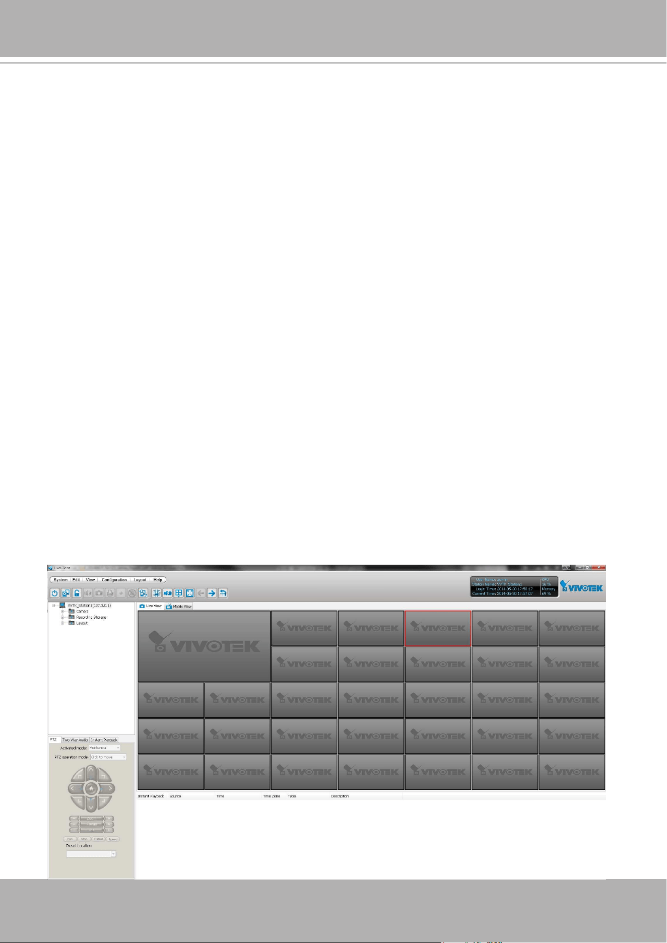
VIVOTEK - A Leading Provider of Multimedia Communication Solutions
User's Manual - 67
VAST LiveClient Functionality
Server function control
Hierarchical station management
User account management
Recording storage management
Recording schedule management
Recorded data backup
Event trigger management
Flexible video live view layout
Dual screens for a maximum of 64 or more channels for simultaneous monitoring
1x1, 2V, 1P+2, 3V, 2x2, 4V, 2V+3, 1+5, 1P+6, 3x3, 1P+8, 1+12, 4x4, 5x5, 8x8, 1+31 moni-
toring layouts (V stands for vertical layout)
1P+2, 1P+6, and 1P+8 Panoramic PTZ layouts
Multiple video viewing pages
Virtual Matrix for video wall display
Intelligent PiP function
E-map for overall management
Network storage for recorded video
Convenient switching among multiple monitors
PTZ / E-PTZ operation panel for camera control
Supports two way audio
Instant playback for event recording
Instant replay for immediate playback
Supports joystick control
Remote configuration for network cameras
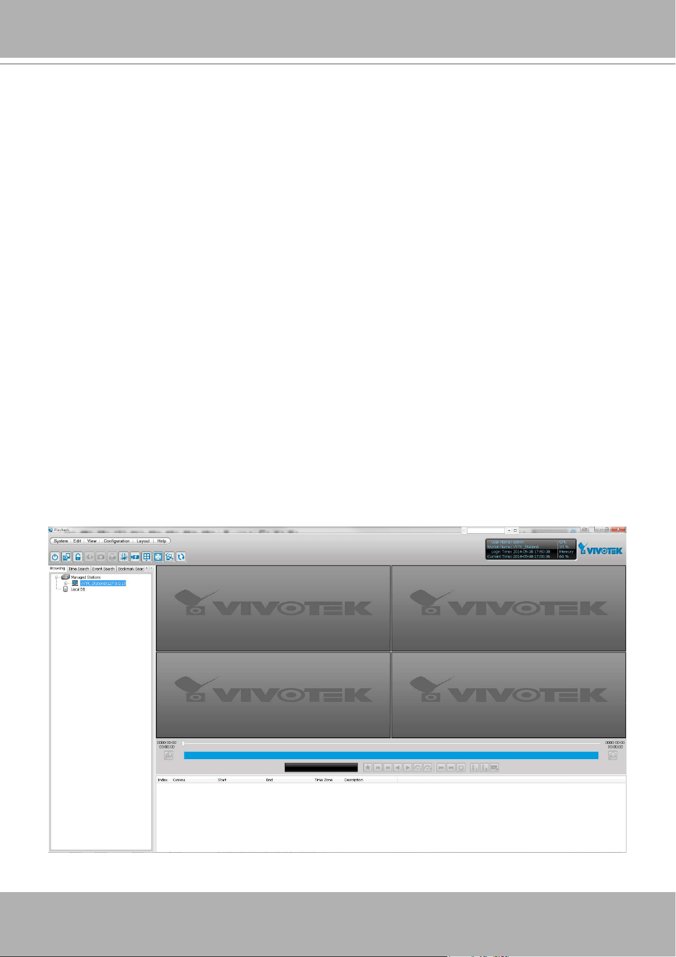
VIVOTEK - A Leading Provider of Multimedia Communication Solutions
68 - User's Manual
VAST Playback Functionality
Browse the database of recorded video from the server
Flexible video playback layout
Maximum 16 channels with simultaneous playback
1x1, 2V, 3V, 2x2, 4V, 2V+3, 1+5, 3x3, 1+12, 4x4 video playback layouts
Supports powerful playback functions
1/8x, 1/4x, 1/2x slow-down playback
2x, 4x, 8x, 16x, 32x, 64x video playback speed
Intelligent PiP function
Supports convenient evidence and data exporting
Export media files of recorded video
Supports snapshot and print out
Supports convenient switch among multiple monitors
Search engine:
Time search
Event search
Bookmark search
Alarm and Log search
Alarm search result export
Playback while recording
Support synchronous/ asynchronous playback
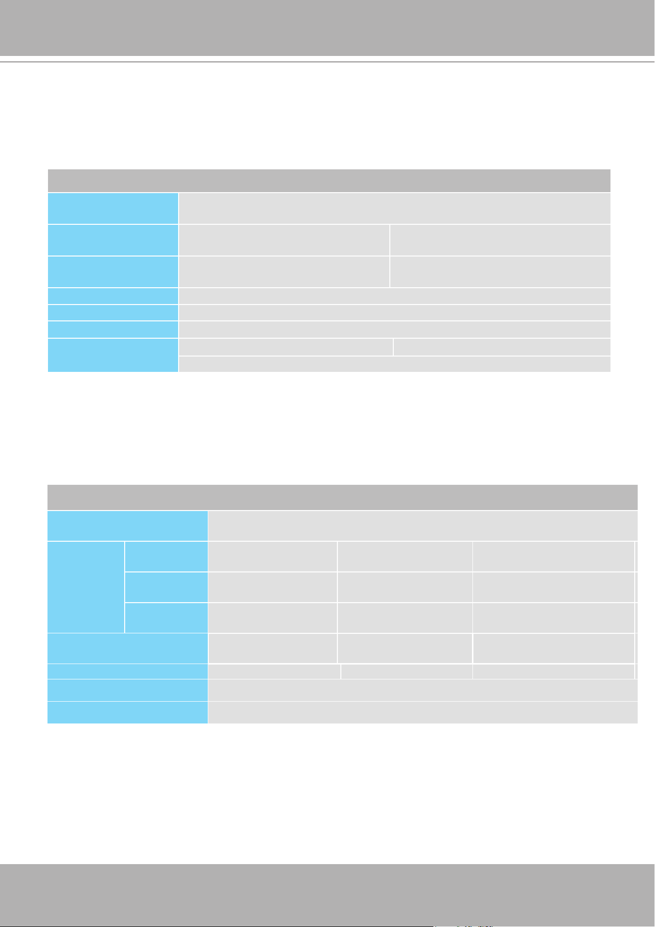
VIVOTEK - A Leading Provider of Multimedia Communication Solutions
User's Manual - 69
Minimum System Requirements
Before installing the VAST software, please make sure your system meets the following
recommended minimum system requirements.
If you would like to install ST7501 Server only, please follow the requirements as below:
Server
Operating System
Windows Server 2000, 2003, 2008, 2012 / Windows XP Professional, Windows
7, Windows 8
Recording Channels
(4Mbps per CH)
up to 64 CH (256Mbps throughput) Up to 128CH (512Mbps throughput)
CPU
3rd Generation Intel
®
Core™ i5
Processors or above
3rd Generation Intel
®
Core™ i7
Processors or above
RAM 4GB or above - 64CH; 8GB or above - 128CH
Network Interface Card Ethernet, 1 Gbit recommended
Graphics Adapter
DirectX 9 compatible 1GB graphics card
Hard Disk Type
Single recording group w/ one HDD Two recording group w/ two HDDs*
SATA, SCSI, SAS (7200 rpm or faster) in NTFS format
LiveClient and Playback
Operating System
Windows Server 2000, 2003, 2008, 2012 / Windows XP Professional, Windows
Vista, Windows 7, Windows 8
Clients
(Display
Channels)
720P,4Mbps,
H.264*
8CH 16CH 32CH
1080P,4Mbps,
H.264**
4CH 10CH 18 CH
1080P,4Mbps,
H.265
2CH 5CH 9CH
CPU
3rd Generation Intel
®
Core™ i3 Processors
3rd Generation Intel
®
Core™ i5 Processors
3rd Generation Intel
®
Core™
i7 Processors
RAM 2 GB or above 4GB or above 4GB or above
Network Interface Card Ethernet, 1Gbit recommended
Graphics Adapter
DirectX 9 compatible 1GB graphics card
* Each recording group can receive recordings for 60 channels.
If you would like to install both the server and client programs, please follow the requirements as
below:
* Display requirements of the 3MP sheye camera is equal to a 720P camera.
** Display requirements of the 5MP sheye camera is equal to a 1080P camera.
If installing Server and Client on the same PC, the overall loading on the PC is to be evaluated.

VIVOTEK - A Leading Provider of Multimedia Communication Solutions
70 - User's Manual
Only users with Administrator privileges can install or use VAST on a Windows Vista system.
The required hard disk space will depend on the video settings, the number of network cameras and recording
group settings. Please add more hard disks if you want to extend the system.
Below are approximate numbers for a week-long recording. The actual storage space required also depends on
imaging parameters, e.g., a complex retail environment that involves many moving objects requires more pixel
data to be transmitted over network than a simple environment such as a parking lot.
32-CH, VGA, about 1 week recording: 750 GB
64-CH, VGA, about 1 week recording: 1TB x 2
32-CH, 2-megapixel, about 1 week recording: 2TB x 2
64-CH, 2-megapixel, about 1 week recording: 2TB x 4
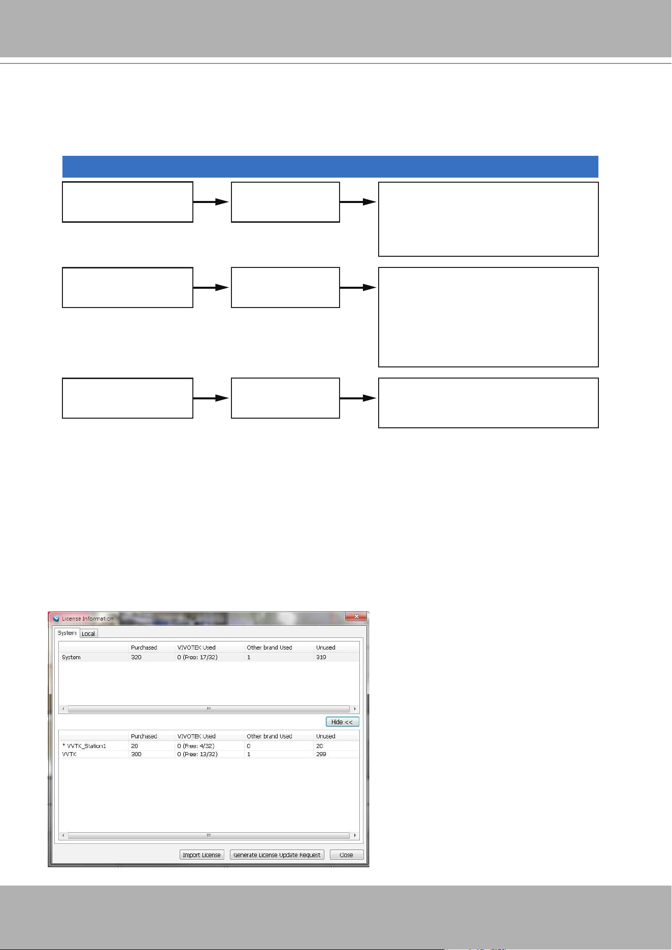
VIVOTEK - A Leading Provider of Multimedia Communication Solutions
User's Manual - 71
Dongle license users
Scenario Need Action
Need more CHs 1. Help > License > export license.
2. Send license file to VIVOTEK to
purchase more dongle license.
New users preferring
more than 32 CHs
Need more than
32 CHs.
1. Install the 256 CH trial VAST.
3. Send request file to VIVOTEK to
purchase software license.
2. Help > License > Generate license
update request.
New users fine with
32 CHs
Fine with less than
32 CHs.
1. Install the 32 CH free VAST.
VAST Software License
To activate the software, refer to the ow chart below:
The VAST software provides 32 free channels. Since revision 1.11, the VAST software is
activated using a software license instead of the original hardware dongle.
For users running the previous dongle version, there is no need to upgrade their original license.
If they need the license for more channels, They can export their license le, and purchase more
dongle licenses.
For users who require more than 32 channels, they can install the 256 channel trial version rst,
and go to
Help
>
License
page, and click on
Generate License Update Request.
Send the
request back to VIVOTEK to purchase more channel licenses.
When you purchased and received the
official software license, use the
Import
License
function to activate the official
license.
When importing purchased licenses, you
can manally select which station/license
le to update, or click the
Auto Dispatch
button and let system decide the
distribution of license updates especially
when there are substations under a
managing VAST server.
Before the Auto Dispatch function is
available, license has to be individually
updated on every substations.
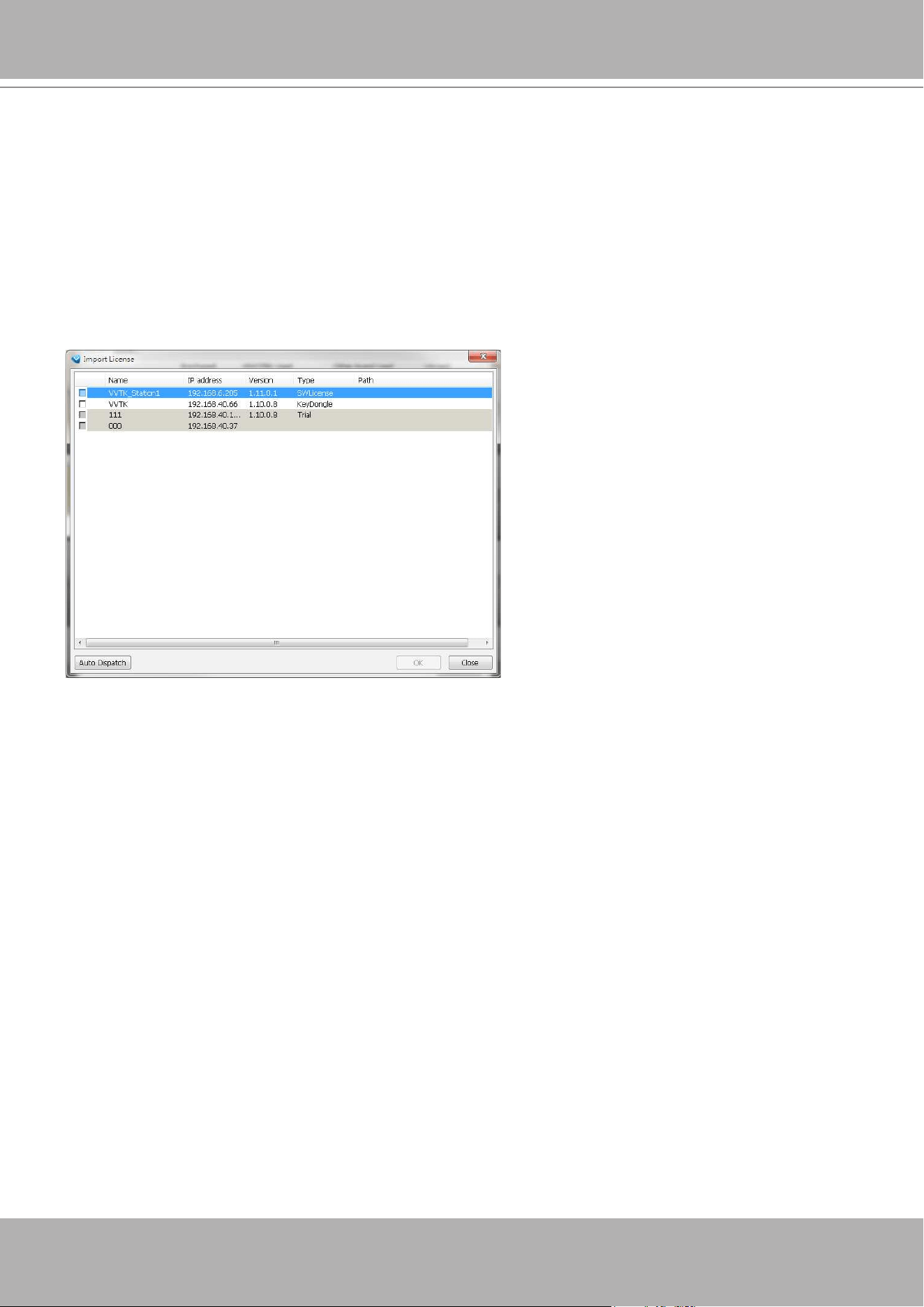
VIVOTEK - A Leading Provider of Multimedia Communication Solutions
72 - User's Manual
Limitations
:
1. The Batch import/export function applies when a managing VAST server needs to collect and
update the licensing information from subordinate VAST substations and itself. An enterprise
may have a central management server and several VAST instances running in branch offic-
es. In that case, the substations will be listed on the device list, and may not be displayed on a
hierarchical structure.
The Batch import/export function is accessed through the
Help
>
License
menu on LiveCli-
ent.
Reminders for VAST Software License
2. The batch download/import function only takes effect on a VAST instance running on server,
not on the Linux-based NVR.
3. The trial channels on VAST substations will not be available for use on a managing VAST
server (one that manages multiple substations).
4. If you access a VAST deployment via a web console, the license related information will not
be available.
5. In this revision, an identical software license applies to both VIVOTEK and other-brand cam-
eras (ONVIF). You do not need to activate two different kinds of software licenses.
6. The Batch export update of the current license profile is supported.
7. The licensing mechanism does not apply to machines running Virtualized OSes (
VMWare
,
VirtualBox
,
Hyper-V
,
Parallels
), either through an upgrade or generating software license on
a new installation.
8. If VAST is removed and then re-installed, the number of licensed channels remains intact.
9. If users plan to integrate the software licenses from previous dongle licenses, problems may
occur if users changed the exported license file name.

VIVOTEK - A Leading Provider of Multimedia Communication Solutions
User's Manual - 73
10. The VAST rev. 1.11 supports 32 free channels, and trial licenses for up to 256 channels.
Note that the unused trial licenses in a VAST substation will not be available for a managing
VAST server. The 32 free licenses will be available for a stand-alone VAST server only.
11. The software license verifies its availability on a machine by checking the computer’s main
components, e.g., GPU or memory. If a VAST server has several of its main components re-
placed, the software license may become invalid. Note that users can only change 2 compo-
nents on a substation (server components - CPU/Memory/Graphics card/Network card/Main
board).
12. For an older VAST installation containing a VAST substation licensed through the dongle, the
32 free channels will be automatically added to the total number of licensed channels. One
substation comes with 32 free channels. The added number of licensed channels will be-
come available for the managing VAST server.
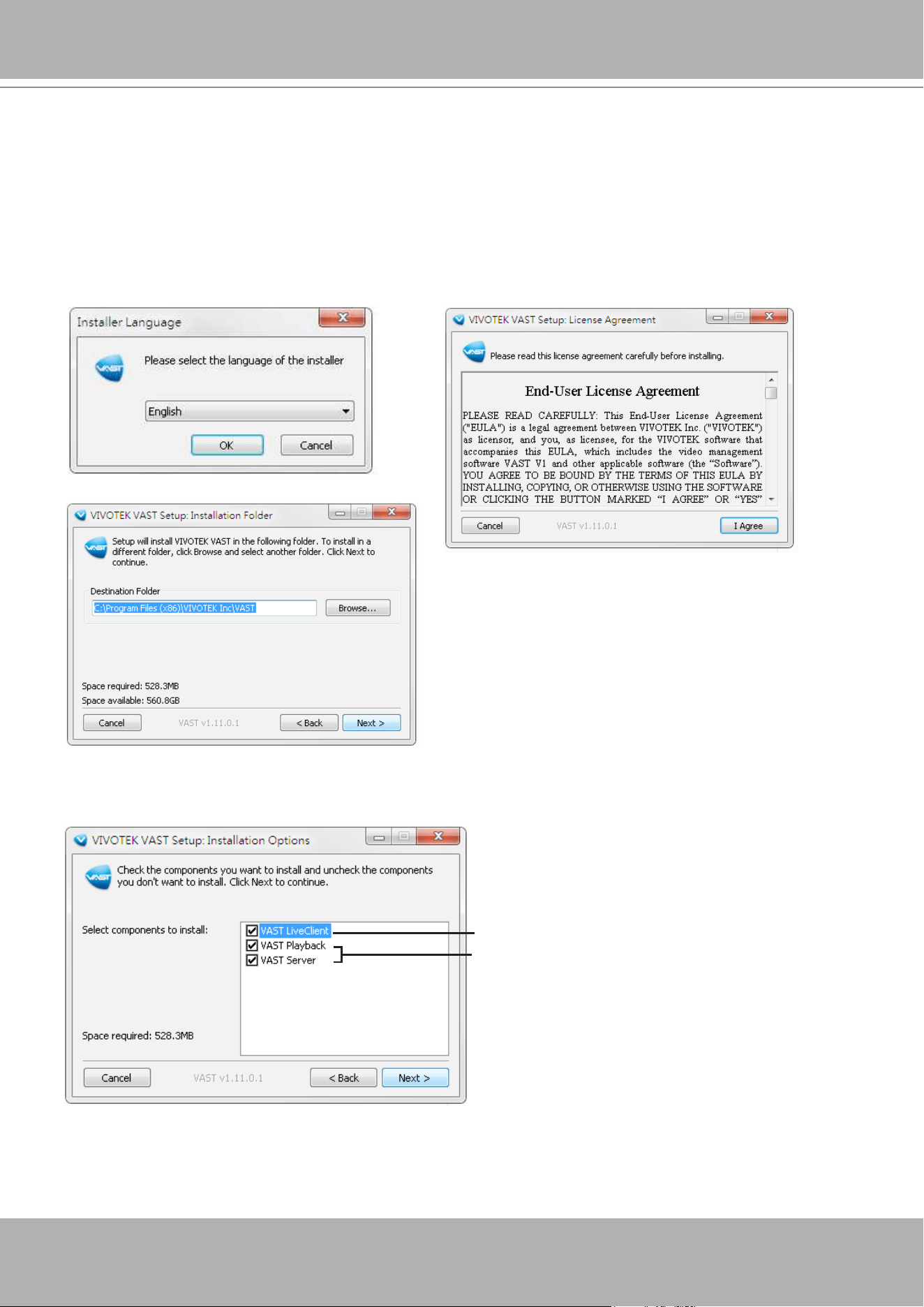
VIVOTEK - A Leading Provider of Multimedia Communication Solutions
74 - User's Manual
VAST Installation
Installing the VAST Software (This is in case you need to re-install
the software)
1. Run
VAST_Setup.exe
on your computer. Select the displayed language. Click
I ACCEPT
the License
Agreement and specify a location to install the program.
Server component
Client components
2. Select the items you want to install, then click
Next
to continue.
If you want to install both VAST Server component and Client components, please follow the steps
below to install the database.
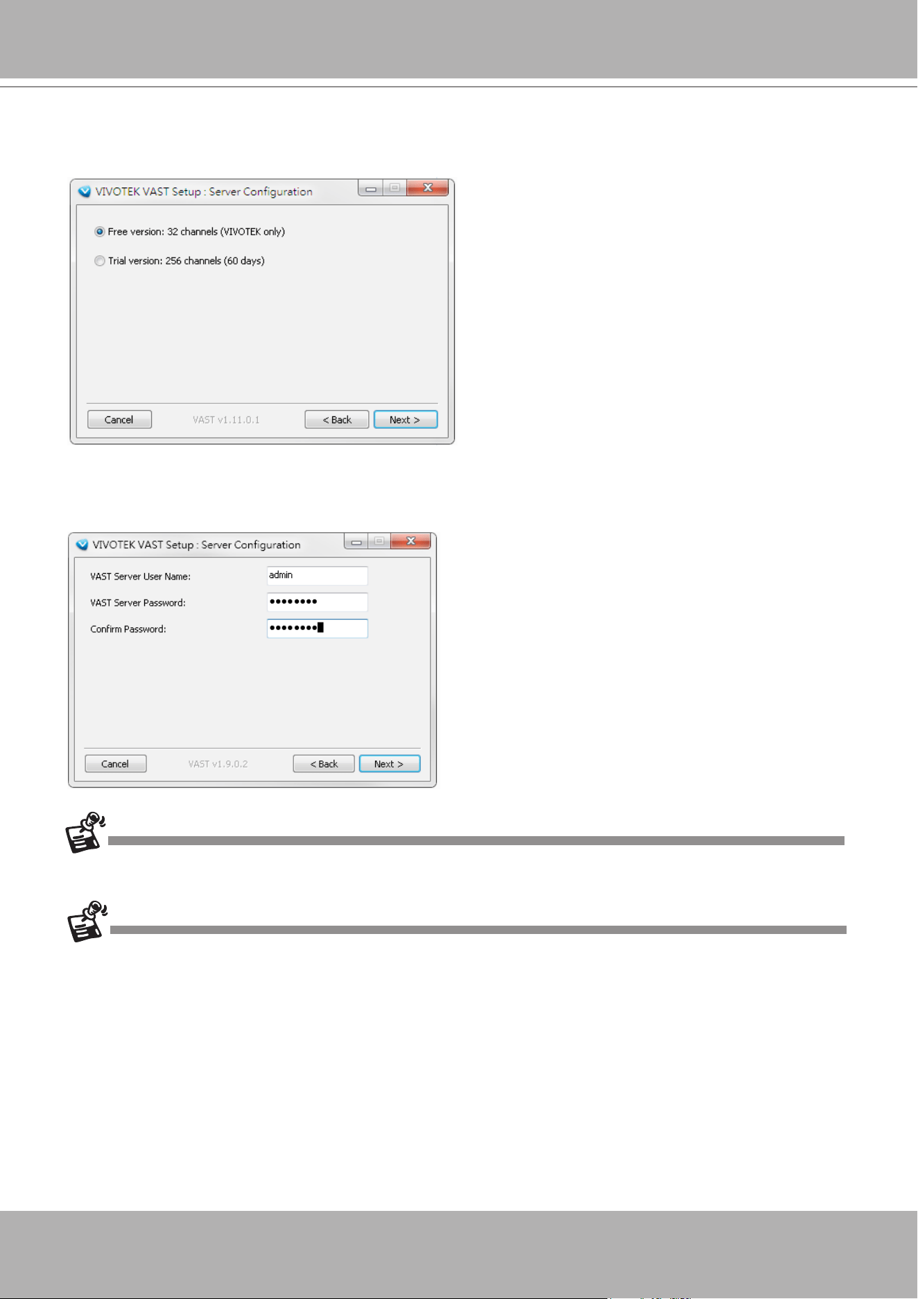
VIVOTEK - A Leading Provider of Multimedia Communication Solutions
User's Manual - 75
4. Assign a
username
and
password
for the VAST Server and click
Next
to continue. A strong password
is recommended using a minimum of 8 characters, in upper/lower case, and special characters.
Resetting passwords regularly is also recommended.
3. You can install the free 32 CH version, or, select the Trial 256 CH version, then click
Next
to continue.
The trial version will expire after 60 days. You can then contact VIVOTEK's sales representatives to
purchase the ofcial software license to continue using the software.
Please record the user name and password for login later.
In the LiveClient window, you can go to
Help
>
License
, and click on
Generate License
Update Request
. You can send the request le to
VIVOTEK's sales representatives to facilitate the
purchase process.
Once you have created a user account for a VAST station, you can login to VAST Server from any computer over
the network through the LiveClient and Playback utilities.
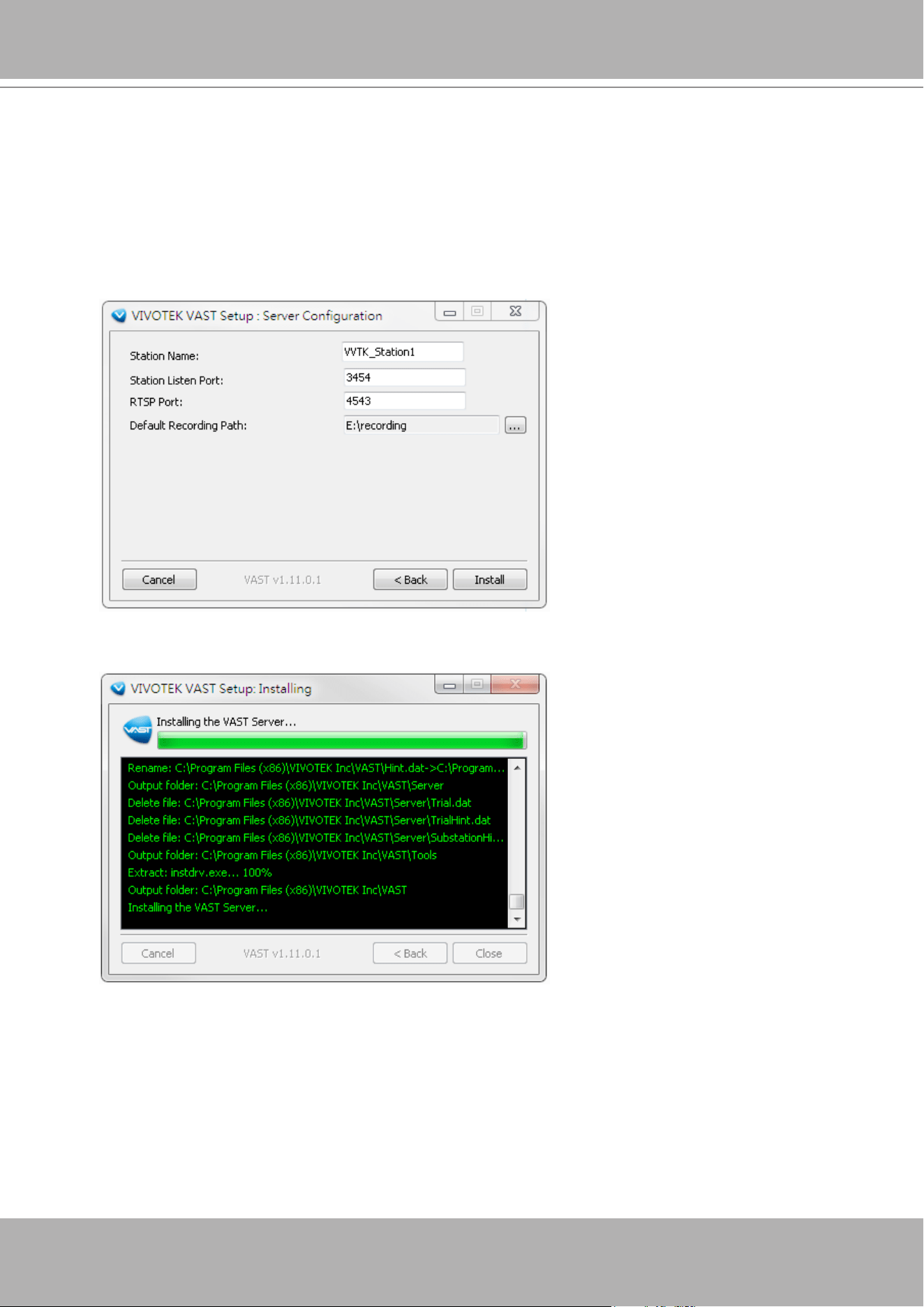
VIVOTEK - A Leading Provider of Multimedia Communication Solutions
76 - User's Manual
5. An SQL Lite database is automatically installed on your server. In order to avoid conflicts among
different databases, we suggest you remove the original database from your computer.
Usually, you do not need to change the Station Listen Port and RTSP port for streaming video. If
necessary, e.g., when the port has been occupied by other applications, change the port number.
Specify a le recording path on your server. Multiple recording groups can be created, and if you have
more than 32 channels, it is recommended to assign a recording path on a different hard drive or RAID
volume disk other than your system drive. Click
Install
to continue the process.
The installation process should be completed within several minutes. Shortcuts will be created on your
desktop. Double-click on the shortcut to start using the software.
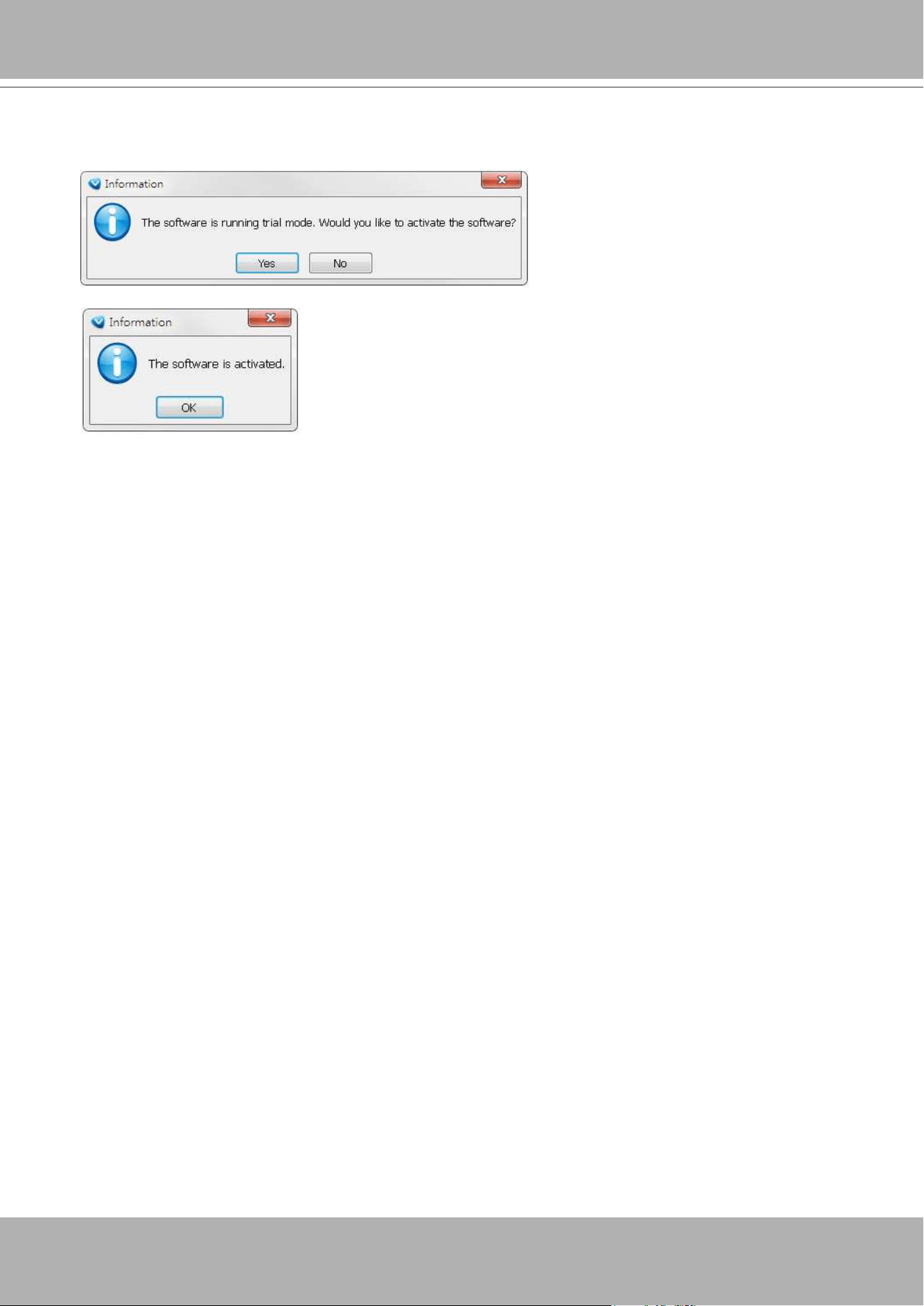
VIVOTEK - A Leading Provider of Multimedia Communication Solutions
User's Manual - 77
If you installed the trial version, you will be prompted to activate the trial license. Click
Yes
to start
using the trial version.
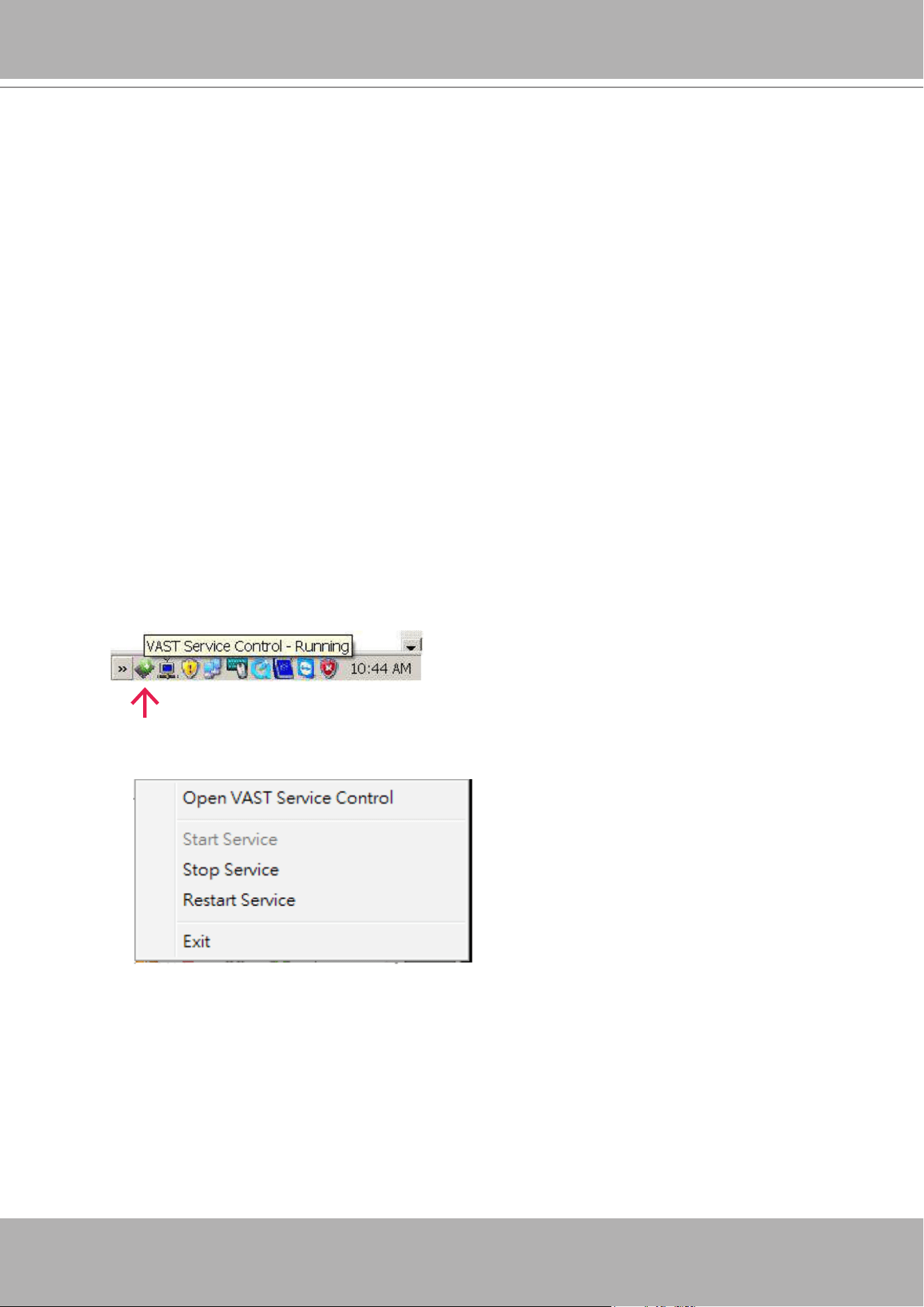
VIVOTEK - A Leading Provider of Multimedia Communication Solutions
78 - User's Manual
VAST Server
Activating the VAST Server
VAST Server is a service program that will run automatically when your VAST station starts.
Users can also deselect the Auto launch option at windows startup on the VAST Service Control
program tray. The program tray icon can be located on Windows tool bar.
How to Congure the Server
Please follow the steps below to congure the VAST Server:
1. Find a local/remote computer that has installed VAST LiveClient.
2. Activate VAST LiveClient and login to the target VAST Server.
3. Congure the server using the VAST LiveClient user interface.
How to Stop/Reboot the Server
Please follow the steps below to stop/reboot the server:
1. Click on the VAST Service Control program tray icon in the toolbar.
2. There are 3 options: Start Service, Stop Service, and Restart Service. It’s selectable by a right-click on
the Service Control program tray icon.
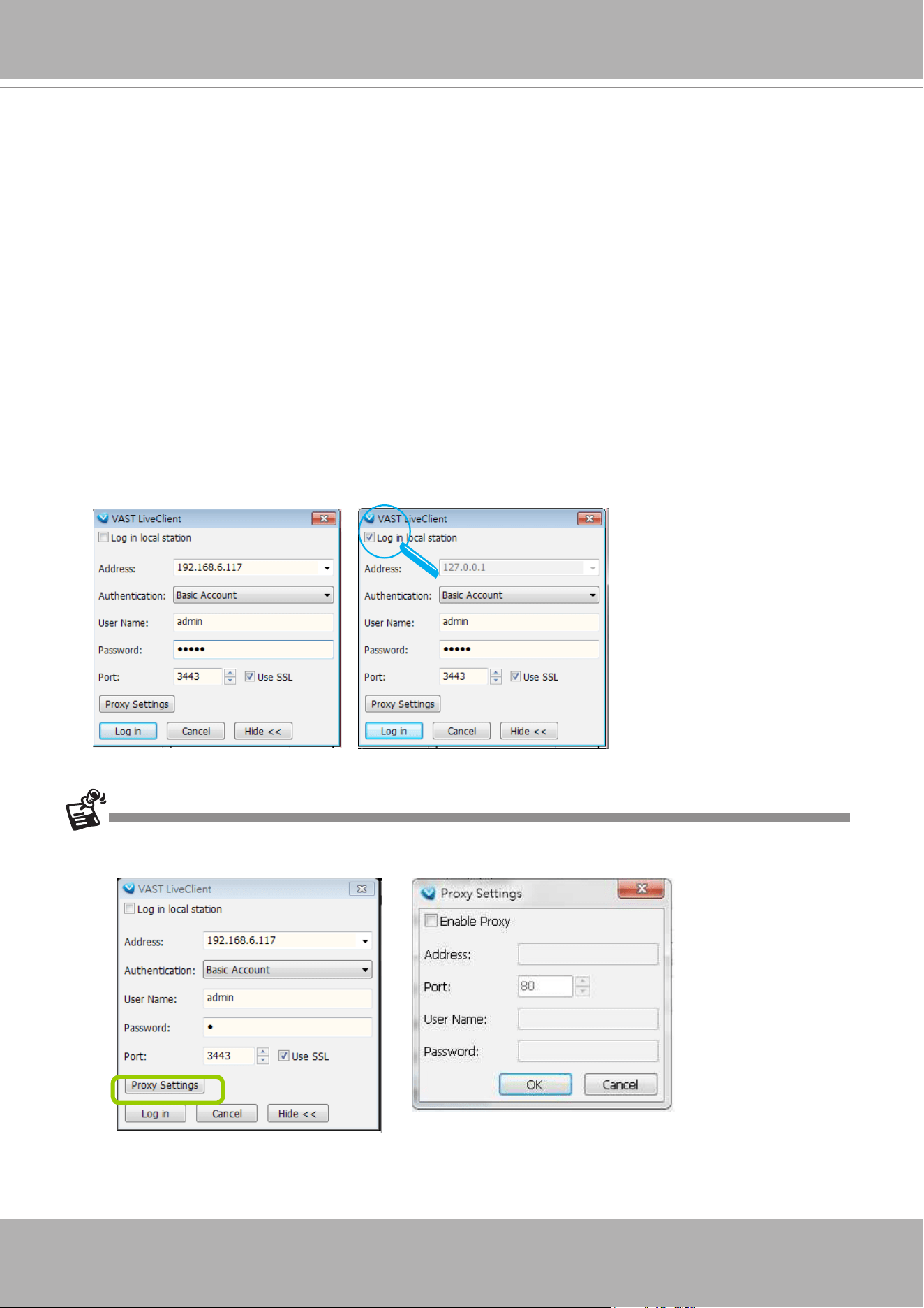
VIVOTEK - A Leading Provider of Multimedia Communication Solutions
User's Manual - 79
VAST LiveClient Conguration
Activating the VAST LiveClient and Logging in to a VAST Server
VAST LiveClient allows you to monitor live video from cameras managed by the VAST Server; it
is also the main user interface for server function control.
After installing the VAST LiveClient program, please follow the steps below to activate VAST
LiveClient:
1. Run the
VAST LiveClient
program.
2. A
Login
window will pop up. Enter the information as shown below:
If you want to login to a remote VAST Server, enter the
IP Address
,
User Name
,
Password
and the
Communication Port
of the target server correctly. Click
Login
to log in to the target server.
If you want to login to a local host that is running VAST Server, check the
Login local station
check-
box, then the local
IP Address
will be displayed automatically. Enter the
User Name
,
Password
,
and
Communication Port
of the local server for login. Click
Login
to login to the target server.
3. The VAST LiveClient monitoring window will prompt.
If your network environment needs to set up proxy, click
More >>
to extend the login window, then click
Proxy
Settings
to open the dialog. Then enter related information to link to your proxy server.
Available functions of the VAST LiveClient program will be enabled according to the role of your login account.
For more details about the privileges of the user account, please refer to
How to Manage User Accounts
on
page 150.
Please refer to page 153 for
how to enable and configure
Windows AD accounts
.
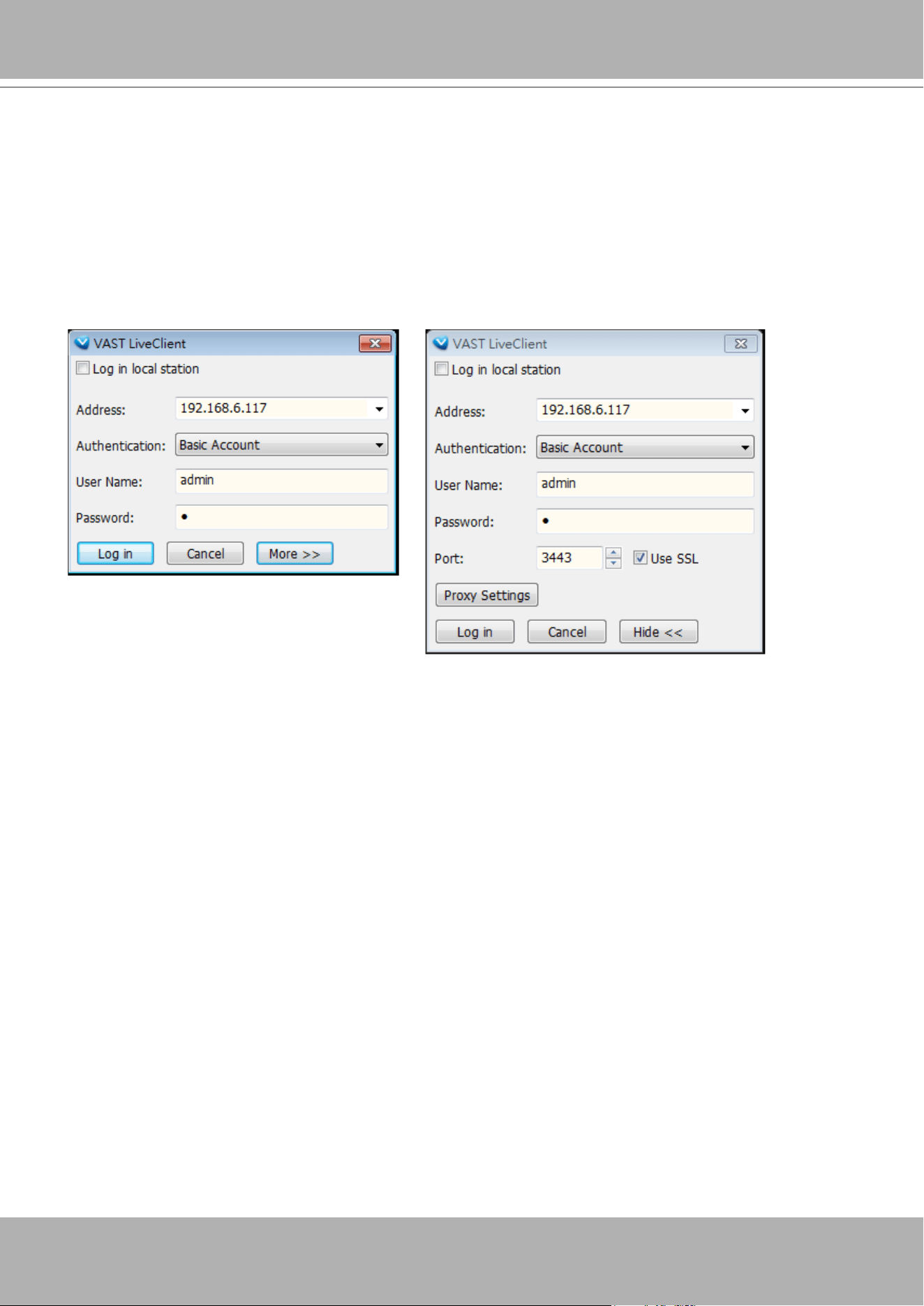
VIVOTEK - A Leading Provider of Multimedia Communication Solutions
80 - User's Manual
If you use LiveClient to access a remote VAST server, you can use the SSL login for secure
connection.
To prevent network layer attack, the management session between a VAST LiveClient and
server can be encrypted using the HTTPS connection. HTTPS (Hypertext Transfer Protocol over
Secure Socket Layer) encrypts the trafc between web browsers and servers.
When starting the LiveClient, click the More button, and select the
Use SSL
checkbox.
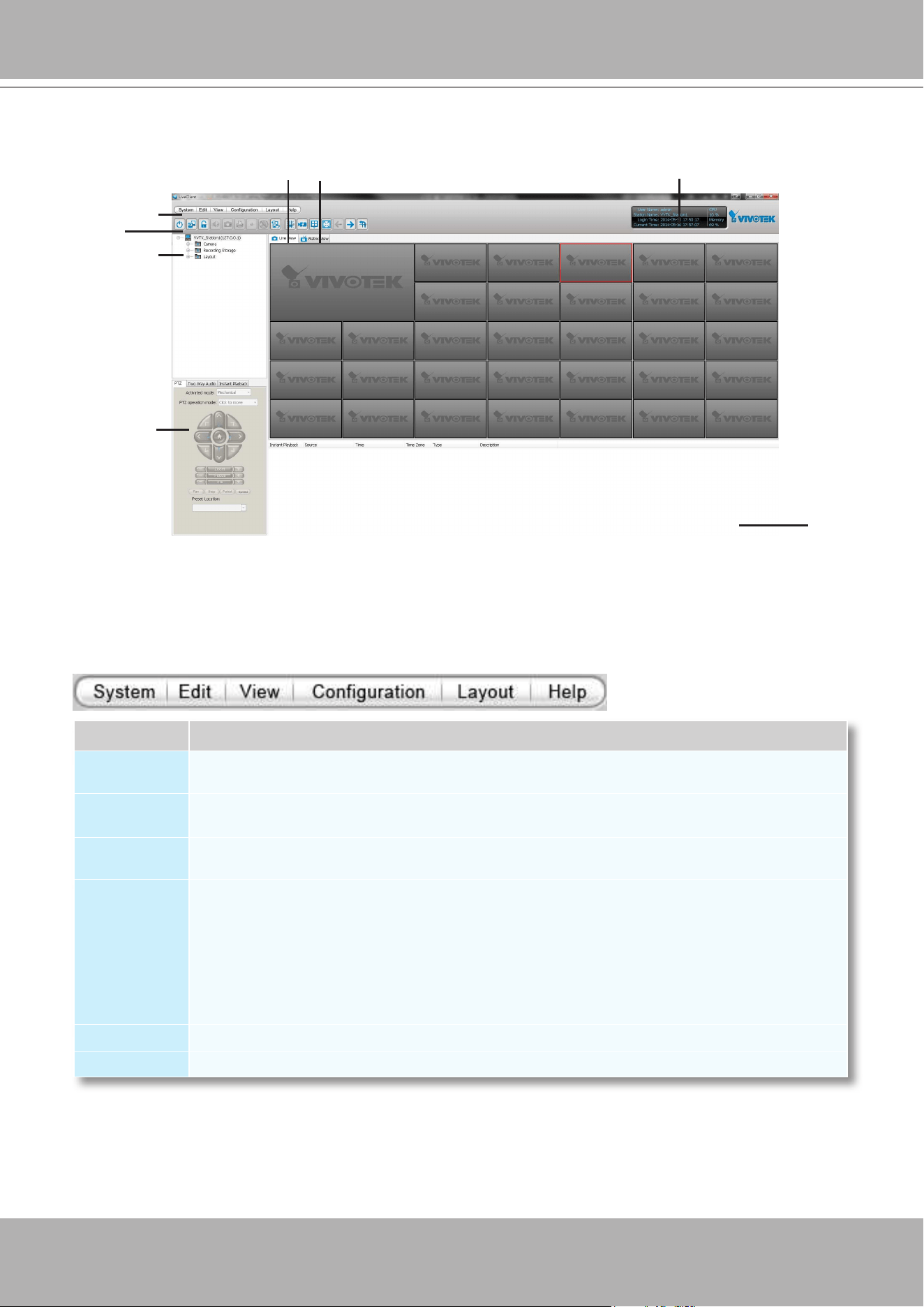
VIVOTEK - A Leading Provider of Multimedia Communication Solutions
User's Manual - 81
VAST LiveClient User Interface
Menu Bar
E
C
B
G
A
D
Menu Item Drop-down Options
System
Lock / Enable Click On Image (Disable Click On Image) / Language / Second View / E-map /
Launch Playback / Logout / Exit
Edit
Manually Begin Recording (Stop Manual Recording) / Snapshot / Print / Record to EXE (3GP,
AVI) / Snapshot Zoomed Image / Print Zoomed Image / Find
View
Logical Tree view/ Device Tree view/ PTZ Panel / Two Way Audio Panel / Instant Playback
Panel / Alarm Window / Full Screen / Minimize / Matrix View
Conguration
Camera Management (Insert Camera / Update Camera / Delete Cameras / Batch Insert
Cameras / Camera Configuration) / Station Management / Logical Tree View management
/ IO Box Management / User Management / Association Management / Alarm Management
/ Virtual Matrix Management (Matrix Management / Matrix View Settings) / Station Settings
(General Settings / Network Settings / Recording Storage Settings / Recording Schedule
Settings / Scheduled Backup Settings / Server Settings / Relay Settings) / Client Settings
(Snapshot Settings / Recording Settings / View Settings / General Settings / Joystick Settings /
Proxy Settings / PiP Settings) / Video Enhancement (Basic Image Adjustment / Defog)
Layout
Start Rotating (Stop Rotating) / Save to / Delete / Choose
Help
About / License
A. Menu bar B. Quick access bar C. Hierarchical management tree
D. Camera control panel (PTZ / Two way audio / Instant Playback control panel)
E. Live view window F. Matrix view window G. Status panel H. Alarm window
H
F
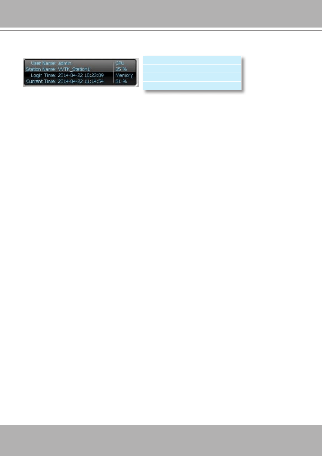
VIVOTEK - A Leading Provider of Multimedia Communication Solutions
82 - User's Manual
Status Panel
User Name
Station Name (IP Address)
Login Time (yyyy-mm-dd hh:mm:ss)
Current Time (yyyy-mm-dd hh:mm:ss)
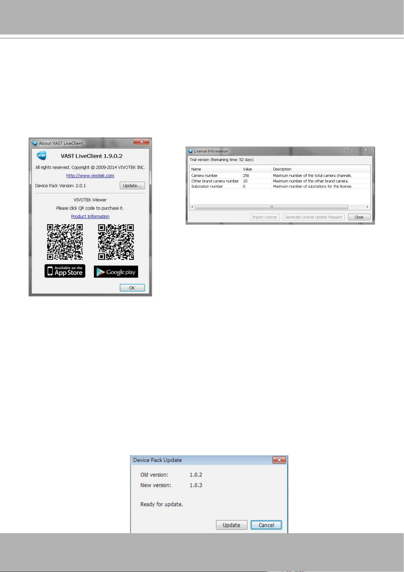
VIVOTEK - A Leading Provider of Multimedia Communication Solutions
User's Manual - 83
Help Panel
The Help panel provides software revision information and the access to the associated iViewer
software in either the iOS or Android version. You can also click on the License button to review
the number of cameras and manageable substations.
If necessary, you may also use the Import License button to activate the functionality you
separately purchased or generate a license request.
Device Pack Update
A Device Pack consists of information of new VIVOTEK cameras or the updated information
for previous models, such as various congurations including resolutions, FPS, DI/DO, etc. For
example, some panels, such as the PTZ panel, may not be available for a new PTZ camera.
Your VAST server might not recognize the features of the latest VIVOTEK cameras. With the
Device Pack, you can congure and implement the latest VIVOTEK models without the need
to upgrade the entire VAST software to acquire the associated information. Please visit:
http://
www.vivotek.com/web/product/productdetail.aspx?Model=VAST. For congurations not specied
in the device pack, you can still open a web console with individual cameras to change their
conguration.
You can consult VIVOTEK's technical support for the latest Device Pack [CSV files (*.csv)],
and use the Update... button in the Help window to replenish camera information. The update
information will be displayed, and the update process is completed almost immediately.
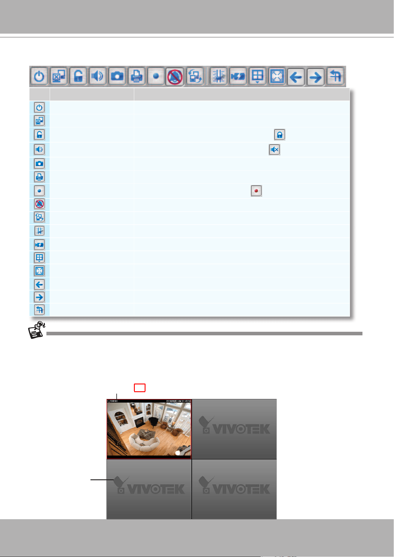
VIVOTEK - A Leading Provider of Multimedia Communication Solutions
84 - User's Manual
Quick Access Bar
Some buttons will be disabled if the selected devices do not support the corresponding functions.
Live Video Monitoring Window
The "VIVOTEK" logo is displayed where no camera has been assigned to a video cell.
Icon Function Description
Exit
Exit the system
Logout
Log out from the current station
Lock
Click to Lock the system for security concerns (
Unlock the system)
Volume
Adjust the audio volume of the current video (
Mute)
Snapshot
Capture pictures from the focus live video cell
Print
Print out the pictures of focus live view window or all live video cells
Record to Media
Record media in EXE/3GP/AVI format (
Recording Media)
Alert Sound
Play sound when an event triggers
Switch Screen
Switch the current window to another screen
Adjust SVC Level
Dynamically adjust the SVC control over frame rates
Remove All Connections
Remove all live videos from the live view window
Layout
Change the layout of the live view window
Full Screen
Maximize the live video cell
Page Up
Switch to the previous live view page
Page Down
Switch to the next live view page
Start / Stop Rotating
Start or stop live view layout rotating
The red frame ( ) represents the current selection.
Video Cell
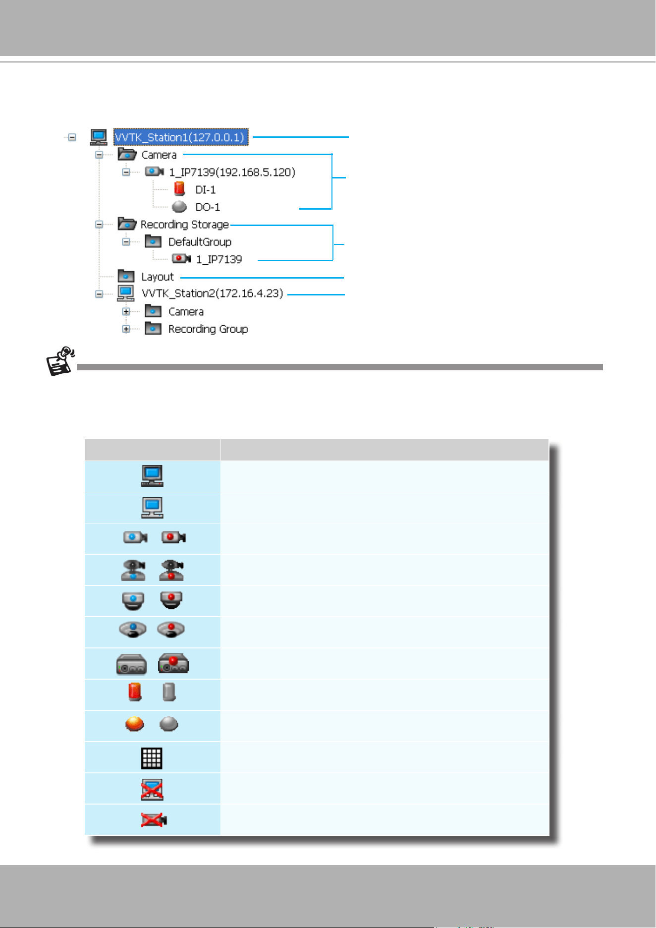
VIVOTEK - A Leading Provider of Multimedia Communication Solutions
User's Manual - 85
Hierarchical Management Tree
Root Station Name (IP address)
Connected devices listed under the root station
Camera name (IP Address)
Connected devices that have been assigned to
the default recording storage
Layout list
Icon Description
A station (The host that’s installed with VAST Server)
A station (The host that’s installed with ST7501 Server)
/
VIVOTEK xed network camera (or ONVIF cameras)
Red dot signies that the camera is recording.
/
VIVOTEK PTZ network camera
Red dot signies that the camera is recording.
/
VIVOTEK dome network camera
Red dot signies that the camera is recording.
/
VIVOTEK sheye network camera
Red dot indicates that the camera is recording.
/
VIVOTEK video server
Red dot signies that the video server is recording.
/
Digital input on / off
/
Digital output on / off
A layout of the live monitoring window
A station that’s not able to be connected currently.
A device that’s not able to be connected currently.
Sub-station Name (IP address)
By default, the I/O device connection status display is disabled. You can turn up the display by visiting
Conguration
>
Client settings
>
General settings
>
Keep detecting camera DI/DO status.
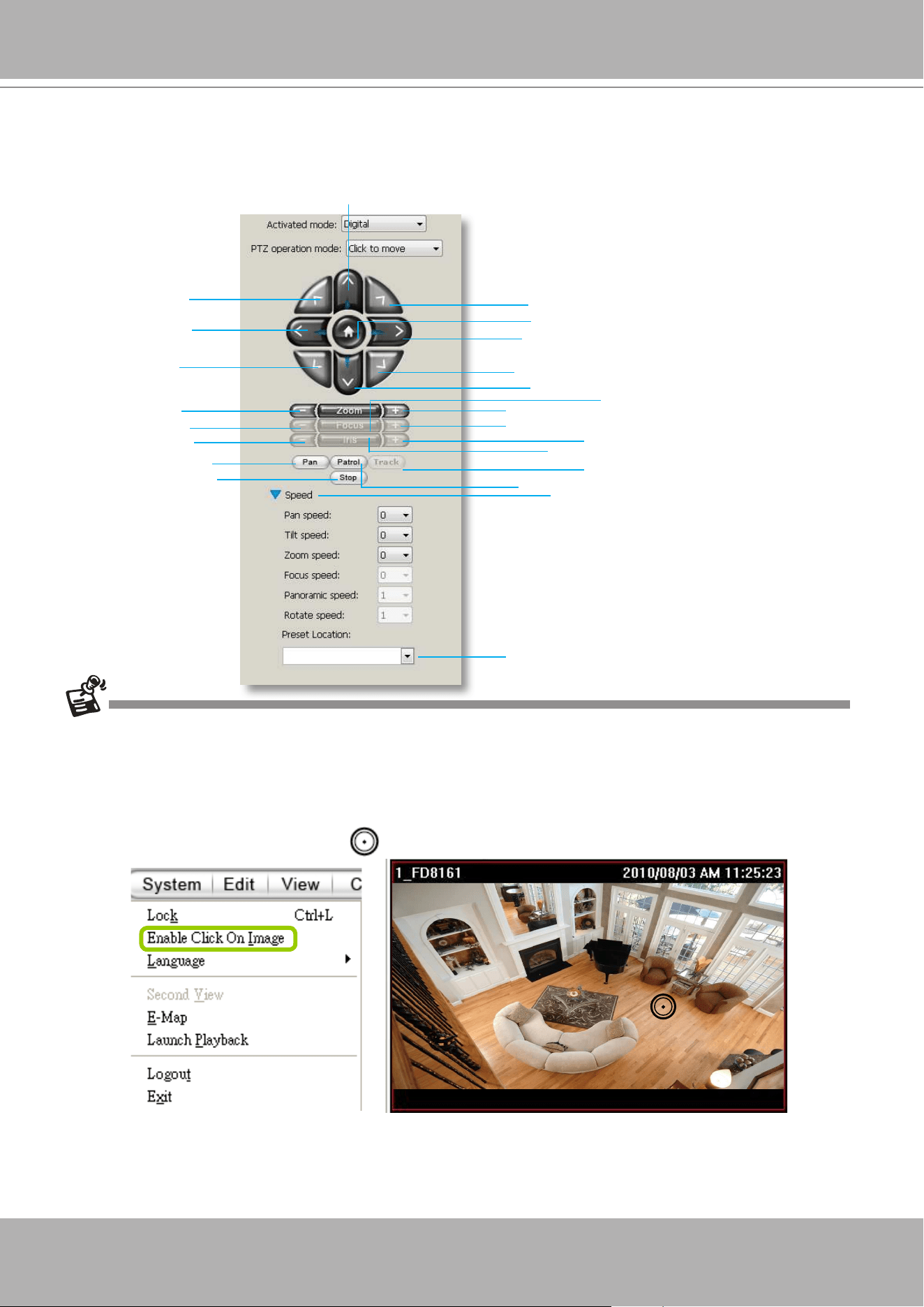
VIVOTEK - A Leading Provider of Multimedia Communication Solutions
86 - User's Manual
Camera Control Panel
Pan/Tilt/Zoom (PTZ) Control Panel
There are two types of PTZ control: Digital (E-PTZ for megapixel cameras) and Mechanical (PTZ cameras or
fixed cameras with camera control via RS-485). If the connected cameras support PTZ/E-PTZ function, the
PTZ option(s) will appear on the drop-down list. For detailed camera control settings, please refer to the user's
manual that came with VIVOTEK network camera .
Click
System > Enable Click On Image
to use the mouse for the control of the PTZ and E-PTZ functions in the
video cells for linked cameras. An icon
will appear in the video cell as shown below.
You can control the PTZ function through joystick as well. For more information regarding to the joystick
conguration, please refer to instructions on page 245.
T
op left
Left
Bottom left
Focus near
Close
Start to auto pan
Zoom out
Up
Return to home position
Bottom right
Right
Top right
Down
Focus far
Zoom in
Open
Start to auto patrol
Stop auto pan/
patrol
Drop-down list of preset positions
Auto focus
Auto iris
Speed control
Auto Tracking
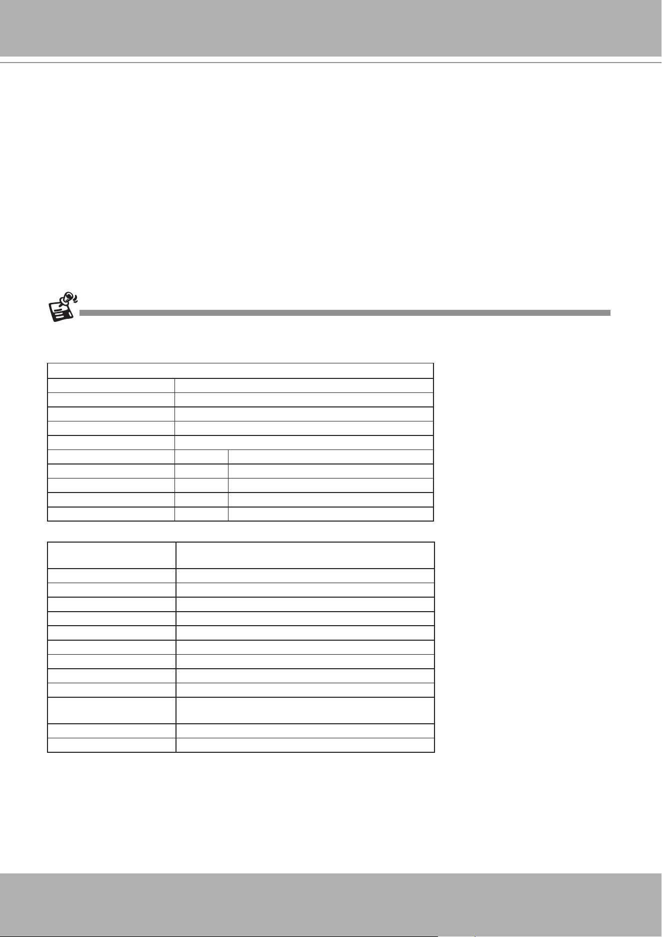
VIVOTEK - A Leading Provider of Multimedia Communication Solutions
User's Manual - 87
In addition to the PTZ panel, the following hot key combinations are also available:
Ctrl + NumPad (PTZ control)
Up Ctrl + 8
Left Ctrl + 4
Home Ctrl + 5
Right Ctrl + 6
Down Ctrl + 2
Focus (Far - Near) Ctrl + 1 Ctrl + 3
Zoom (Out - In) Ctrl + 7 Ctrl + 9
Pan Ctrl + /
Stop Ctrl + *
Patrol Ctrl + -
Preset locations (pre-
congured by users)
Ctrl + 0~9 (number keys above the alphabetic keys)
Full screen Ctrl + F
Single view Ctrl + V
Previous layout page Alt + PageUP
Next layout page Alt + PageDown
First layout page Alt + Home
Last layout page Alt + End
Snapshot Ctrl + S
Stop alarm Ctrl + A
Mute audio from current
stream
Ctrl + M
Start/ Stop rotation Ctrl + O
VIVOTEK's latest SD8xxx speed dome series supports the
Continuous Move
control. The
"
Click to move
" enables one movement by every mouse click on the PTZ buttons.
When Continuous Move is enabled from the PTZ panel, you can click and hold down the
mouse button on an arrow key to command the camera to continue moving to that direction.
The move will stop when you release the mouse button. Also, if the pan/tilt/zoom/focus speed
is congurable for a PTZ camera, you can use the
Speed
button to display the speed options:
pan, tilt, zoom, focus, panoramic, and rotate speeds.
For sheye cameras, two more options will be available: Panoramic speed and Rotate speed.
These two options apply to the onscreen control for the Panoramic and Regional views.
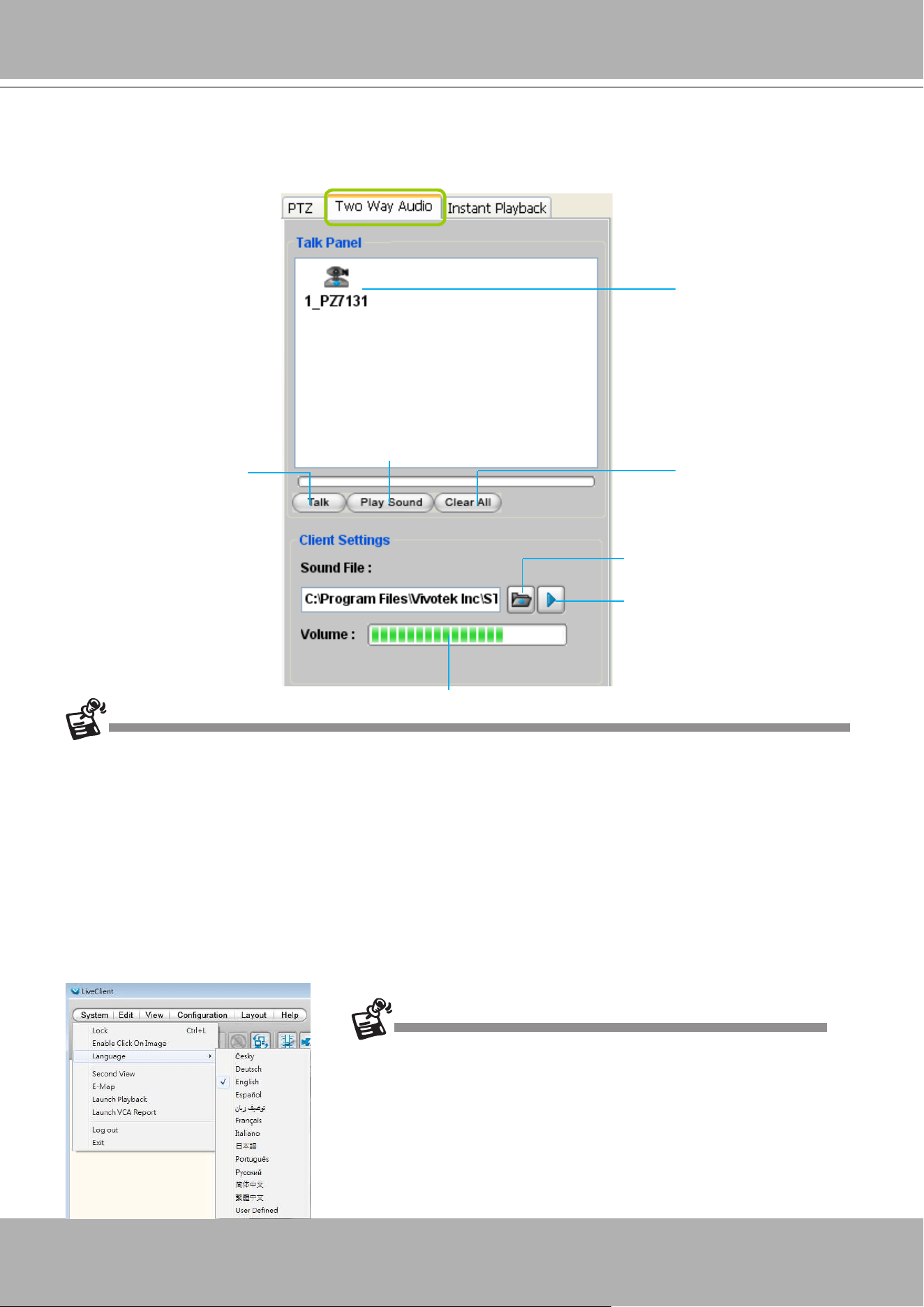
VIVOTEK - A Leading Provider of Multimedia Communication Solutions
88 - User's Manual
Two Way Audio Control Panel
The two way audio function allows the user to remotely communicate with people nearby the
network camera.
For detailed information about
How to Use the Talk Panel
, please refer to page 216.
Only cameras that come with the two way audio function can be added to the Talk Panel.
Language Selection
VAST currently supports multi-lingual user interfaces including:
English, Česky, Deutsch, Espa-
ñol, Farsi, Français, Italiano,
日本語
, Português, Русский,
簡体中文
,
繁體中文
. If you want to select
another language for the interface, please click
System > Language
on the menu bar to select
the desired language. Please note that if you want to change the language option, a message
will prompt to remind you to restart the system.
Remove all cameras
from the Talk Panel
Click to play sound from the camera
Click to talk
Click to adjust volume
Selected device that
can use the two way
audio function
Click to play the selected
sound on the client's side
If you want to use "User Dened" language, please prepare images and
language strings, and upload the les to the following folders:
...\VAST\Client\LiveClient\language\zz_UD (language string)
...\VAST\Client\LiveClient\image (images)
Select sound from the
le list
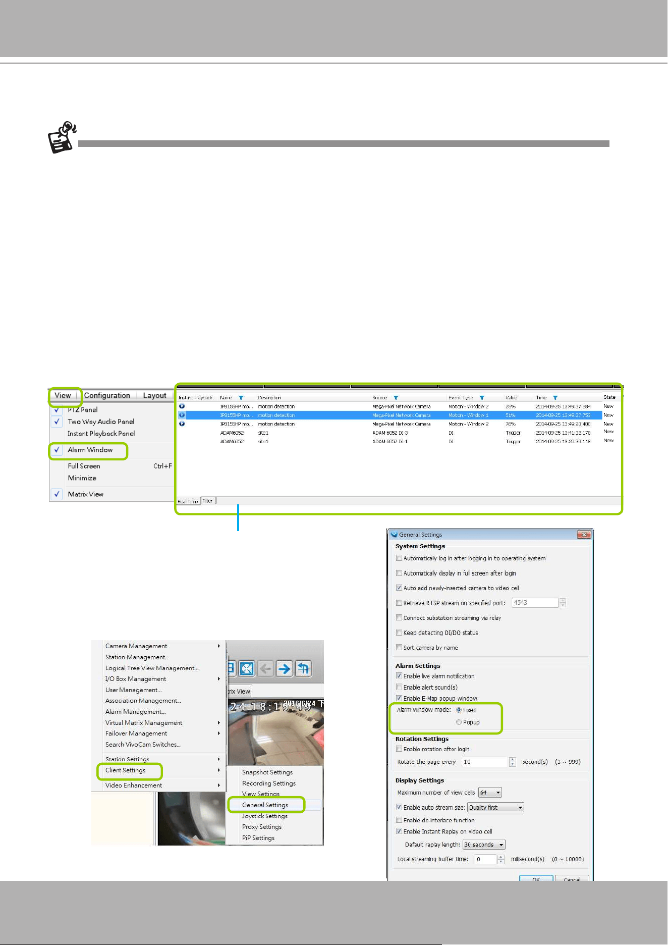
VIVOTEK - A Leading Provider of Multimedia Communication Solutions
User's Manual - 89
Click
View > Alarm Window
to open a window showing the real-time information for event
triggers. If you want to hide this window, deselect this option on the menu bar.
The default Alarm window is set to be fixed on the
bottom of the LiveClient. If you want to change
the Alarm window as a popup page, please open
the
Configuration > Client Settings > General
Settings
window to switch the display modes.
Event Window
Alarm Window
• Only the alarm-related messages will be displayed in this window. An Alarm is a conguration
consisting of triggers and reactions set to activate during a specific period of time. The
Alarm-related settings is congured in
Conguration
>
Alarm management
. See page 161
for more information.
• For the event messages of the overall system operation, please refer to the
Playback
>
Log
viewer
.
• If a VAST server is reset, the Alarms will disappear from the Alarm window. You can go to the
Playback utility and use the
Alarm search
function to retrieve the past events.
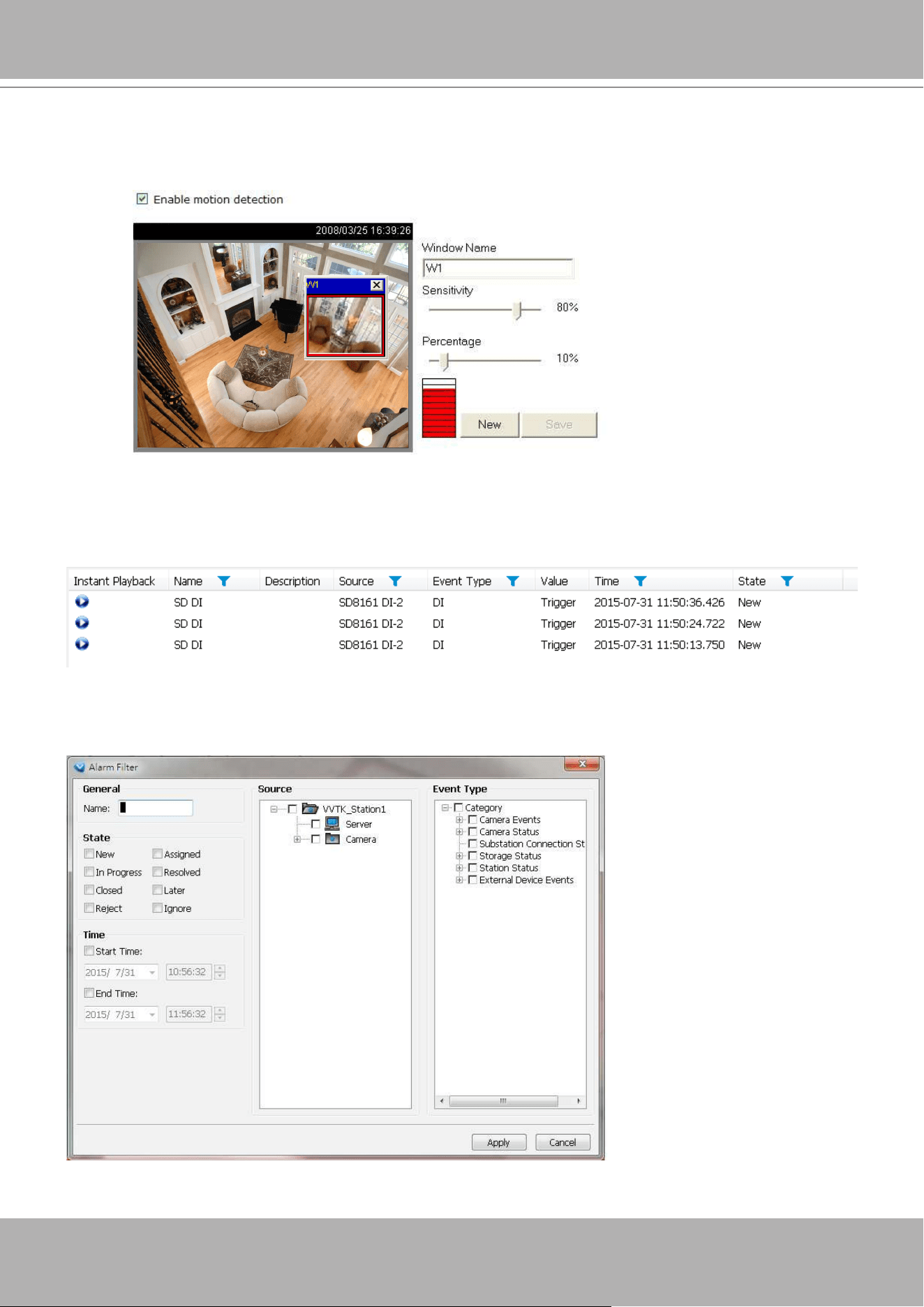
VIVOTEK - A Leading Provider of Multimedia Communication Solutions
90 - User's Manual
Video(TCP-AV)
Alarm Filter
On the Alarm panel, a list of alarms will be displayed. Click on the attributes with a funnel icon.
The Alarm Filter window will prompt. Use the Name, Time selector, and the State checkboxes in
the Source and Event Type panes to specify what kinds of alarms will be displayed.
The
Event Type
eld in the Alarm window shows the event category and another eld
Value
displays
the
percentage
of motion in the detection window. You can go to the Conguration setting page of the
connected device to set the percentage.
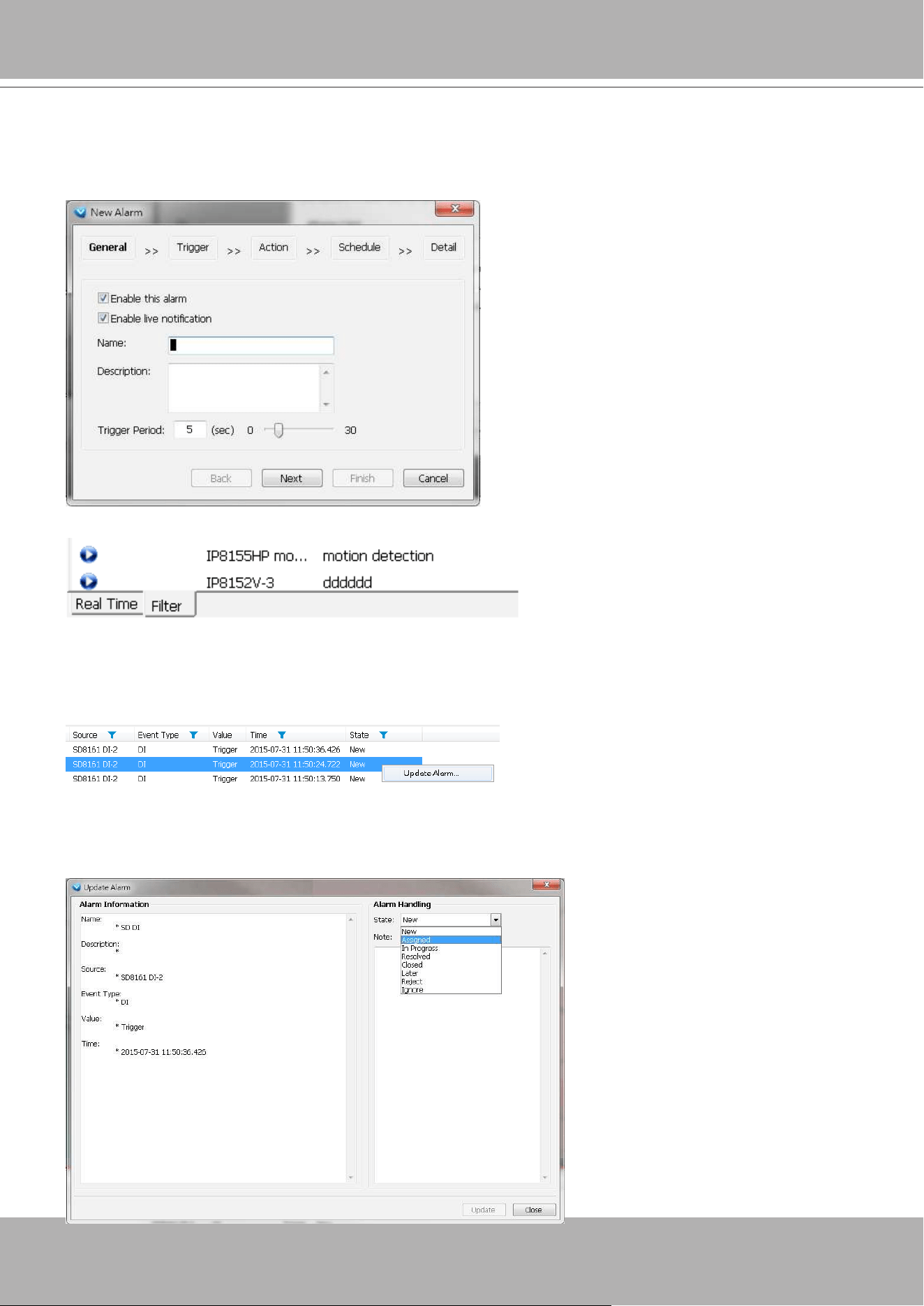
VIVOTEK - A Leading Provider of Multimedia Communication Solutions
User's Manual - 91
Use the Filter tab at the bottom of the Alarm window to display a different sorted result.
For example, you can set up a lter to display the alarms with a name associated with a specic
camera, such as "bullet on the corridor." The name of the alarm is congured in
Conguration
>
Alarm
management on page 161.
Alarm State
Left-click to select an alarm, and then right-click to display the
Update Alarm
button.
You can change the alarm state from the pull-down menu. For example, if someone has already
been sent to check out the situation, for example, an intruder broke in through a window, you
can select the Assigned status. A 1024 bytes decription can be added into the alarm Note for
future reference.
If an alarm is proved as a
false alarm, the alarm can
be designated as Ignore or
Resolved, and so on.
The different alarm states can
also be used as the filtering
conditions in the Alarm filter.
Single or multiple states can
be selected in the filter. For
example, to display the Resolved
alarms only, use the Resolved
state as the lter.
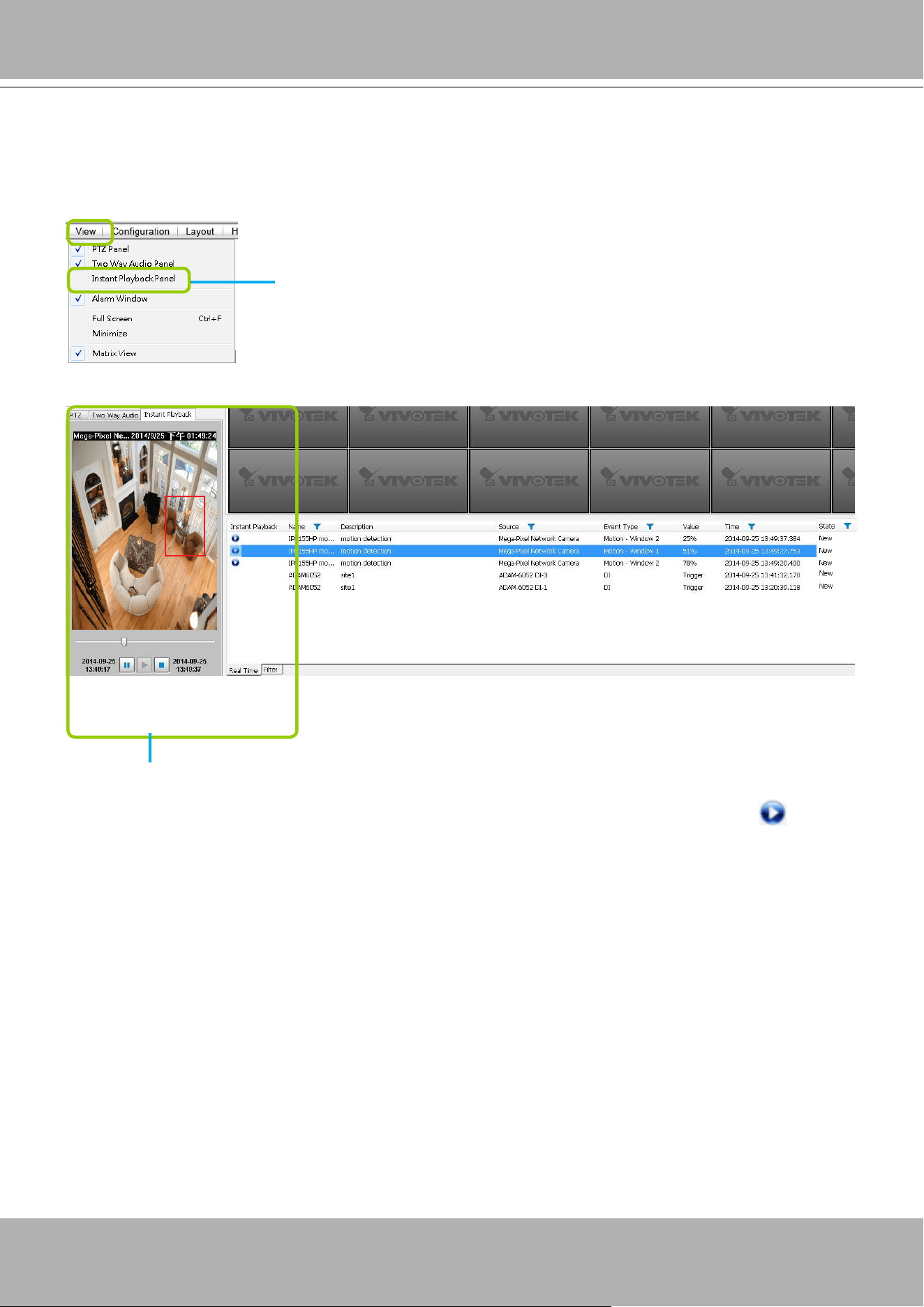
VIVOTEK - A Leading Provider of Multimedia Communication Solutions
92 - User's Manual
Instant Playback
Check
View > Instant Playback
to open the window on the panel. The entries listed in the
Event panel are the short recordings made from triggered events.
The recorded media that was triggered by an event will be indicated with a playable icon.
You can
double-click
an event on the list to playback the recorded video. Each event contains
a video clip of 20 seconds in length. (The default recording data of an event is 20 seconds. For
more information about event recording, please refer to page 187.)
Instant Playback Window with a slide bar, play, pause, and stop function
Deselect this item if you want to hide this window.
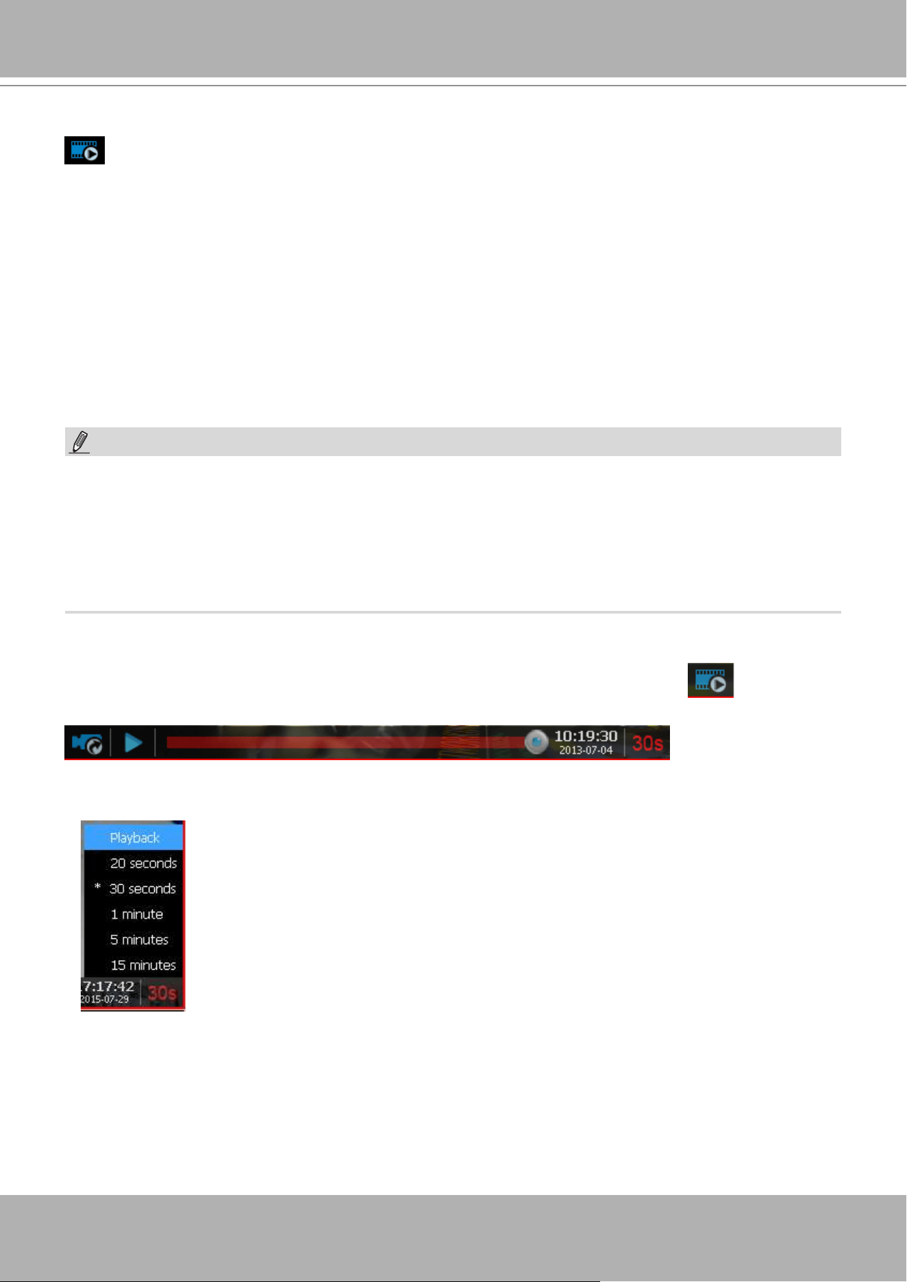
VIVOTEK - A Leading Provider of Multimedia Communication Solutions
User's Manual - 93
Instant Replay
If a camera is currently recording to the VAST server, then a Replay button will be
available at the lower left corner of its view cell. This allows you to immediately retrieve the video
recording in the past few seconds or minutes.
The Instant Replay function enables you to quickly retrieve videos of what has just happened (20
seconds to 15 minutes ago), without the need to open the Playback utility for the past videos.
Prerequisites for Instant Replay:
1. The function is enabled by default, only available on a LiveClient installed on a PC.
2. There must be recorded videos of the immediate past. If the video streams from a camera
were not recorded, you can not retrieve videos using the Instant Replay function.
NOTE:
1. When using the Instant Replay function and you change the stream number on a video cell,
the Instant Replay will be interrupted.
2. The Instant Replay will also be interrupted when the time comes for a rotation of Live View
pages. For example, if you have multiple Live View pages and you set up a rotation of these
pages by every 10 seconds, page swap (rotation) still has a higher priority even if you are
viewing the Instant Replay.
How to Use:
1. On a selected view cell, mouse over to the lower left corner. A Replay icon
will appear.
2. Click on it to display the Replay control bar. Click on the play button.
3. The default queue length is 30 seconds. You can click on the number on the right to change
the queue length.
The Playback option allows you to directly open the Playback utility. A
maximized single view window will open. In this single view, previous
recording will be played, but, unlike the smaller Instant playback pane, the
playback will continue until manually stopped.
This playback mode is not memorized as the norm the next time you use
the Instant Replay function.
The queue length conguration stays with the view cell, and it will not go unless you remove
and insert the camera again.
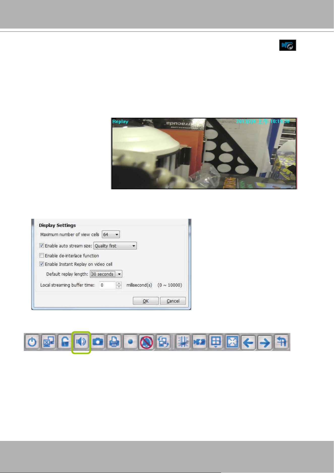
VIVOTEK - A Leading Provider of Multimedia Communication Solutions
94 - User's Manual
Audio Control
The audio function will be enabled if the device is equipped with an internal or external
microphone. For detailed audio control settings, please refer to page 138.
An active Replay view cell is indicated by the Replay text indicator and the time of occurrence
of the current playback.
To change the default Replay settings, open the Conguration > Client Settings > General
Settings menu.
4. To stop the Replay and return to the Live View, click on the
Return to Live
button.
5. On a Replay view cell, you can apply the same Snapshot, Print, Single view and Full screen
control as those on a normal view cell. You can also right-click to display the Display Mode
and Video Enhancement functions.
Click and drag the playhead to skip or move to a different point in time on the playback.
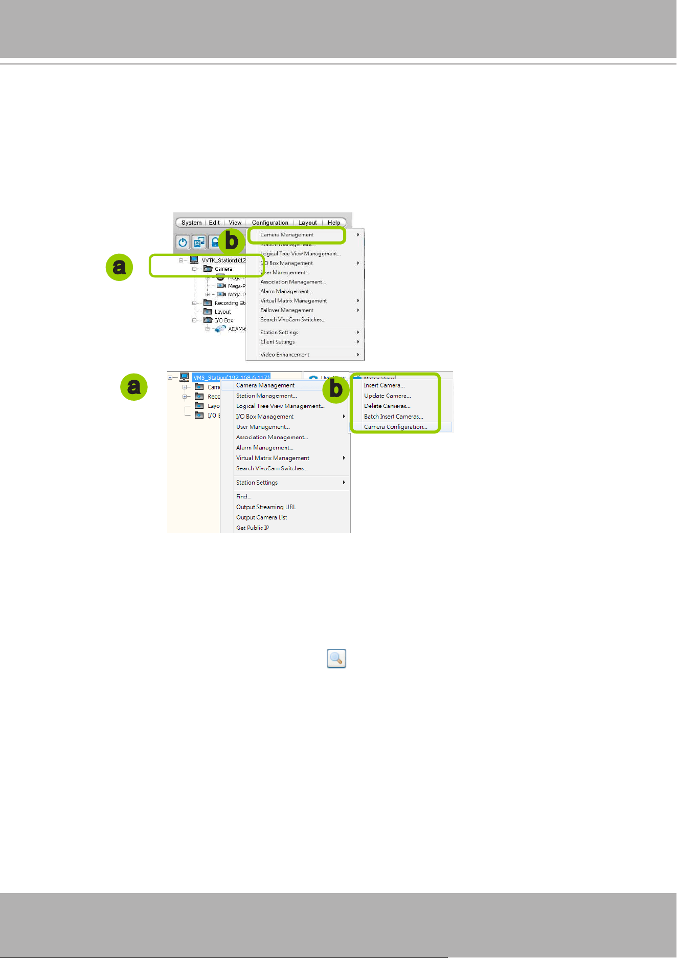
VIVOTEK - A Leading Provider of Multimedia Communication Solutions
User's Manual - 95
How to Manage Devices
Please follow the steps below to open the Camera Management window:
a. Select the station from the hierarchical management tree.
b. Click
Conguration > Camera Management
on the menu bar (or
right-click
the station, then select
Camera Management
).
c. Then you can choose to insert, update, delete, or batch insert cameras.
Insert Cameras
Please follow the steps below to add devices to a station:
a. Click
Conguration > Camera Management
> Insert Camera
on the menu bar (or
right-click
the
device/station, then select
Camera Management > Insert Camera
).
b. The
Camera Management - Insert
window will pop up. The device tree managed by the station will
be displayed in the left Camera List window.
c. Enter the
Camera Name
,
IP address
(or you can enter an
IP address
and check
Auto
to get a
camera name automatically) and congure the
Connection Settings
.
If the camera is on the LAN, you can click
Search Camera
to detect all VIVOTEK network
cameras on the LAN. A
Camera List
window will pop up and show a list of detected cameras on
the LAN. On the top of
Camera List
window, you can select "
List the cameras which are not
inserted
" or "
List all cameras
". The items listed below will then change accordingly. You can click
Mac, IP Address, Model, HTTP port
to sort the items. Then select a camera from the list to insert
to the station.
The streaming protocol determines how
the live video stream is sent from the camera to the local
computer. Please refer to the note on the next page for a detailed description of each transmission
protocol. Specify the recommended live monitoring stream for the device. If you want to change the
live viewing stream, please refer to the next page to update the camera settings. Or you can
right-
click
the desired cell, then select a desired stream. Please refer to Dual / Multiple Streams on page
123 for a detailed illustration.
Click
Detect Model
to detect the device. The Model Name and MAC Address of the device will
automatically be displayed in the respective elds if the connection is successful.
d. If you want to make sure you are connected to the target device, click
Connection Test
to preview the
live video from the device.
b
a
b
a
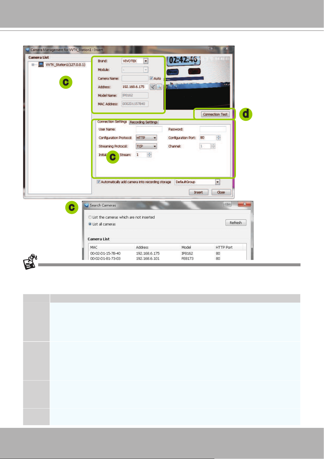
VIVOTEK - A Leading Provider of Multimedia Communication Solutions
96 - User's Manual
If you want to use "HTTPS Port", please enable the HTTPs settings on the conguration page of the Network
Camera rst.
The characteristics of each protocol are shown in the following table:
Protocol Description
UDP
UDP uses a simple transmission model without implicit hand-shaking dialogues for guaranteeing
reliability, ordering, or data integrity. Thus, UDP provides an unreliable service and data grams may
arrive out of order, appear duplicated, or go missing without notice. This protocol allows for almost
real-time audio and video streams. However, network packets may be lost due to network burst
trafc and images may be obscured. Activate UDP connection when occasions require time-sensitive
responses and video quality is less important.
TCP
TCP provides the service of exchanging data reliably directly between two network hosts, whereas IP
handles addressing and routing message across one or more networks. In particular, TCP provides
reliable, ordered delivery of a stream of bytes from a program on one computer to another program
on another computer. This protocol guarantees the delivery of streaming data and thus provides
better video quality. The downside with this protocol is that the real-time effect is worse than that with
UDP for a narrower bandwidth.
HTTP
HTTP is a networking protocol for distributed, collaborative, hypermedia information systems. It’s the
foundation of data communication for the World Wide Web. This protocol allows for the same quality
as TCP and the users need not open a specic port for streaming under some network environment.
Users inside a rewall can utilize this protocol to allow streaming data through.
HTTPS
This protocol enables authentication and encrypted communication over SSL (Secure Socket Layer),
which protects streaming data transmission over the Internet on higer security level.
d
c
c
c
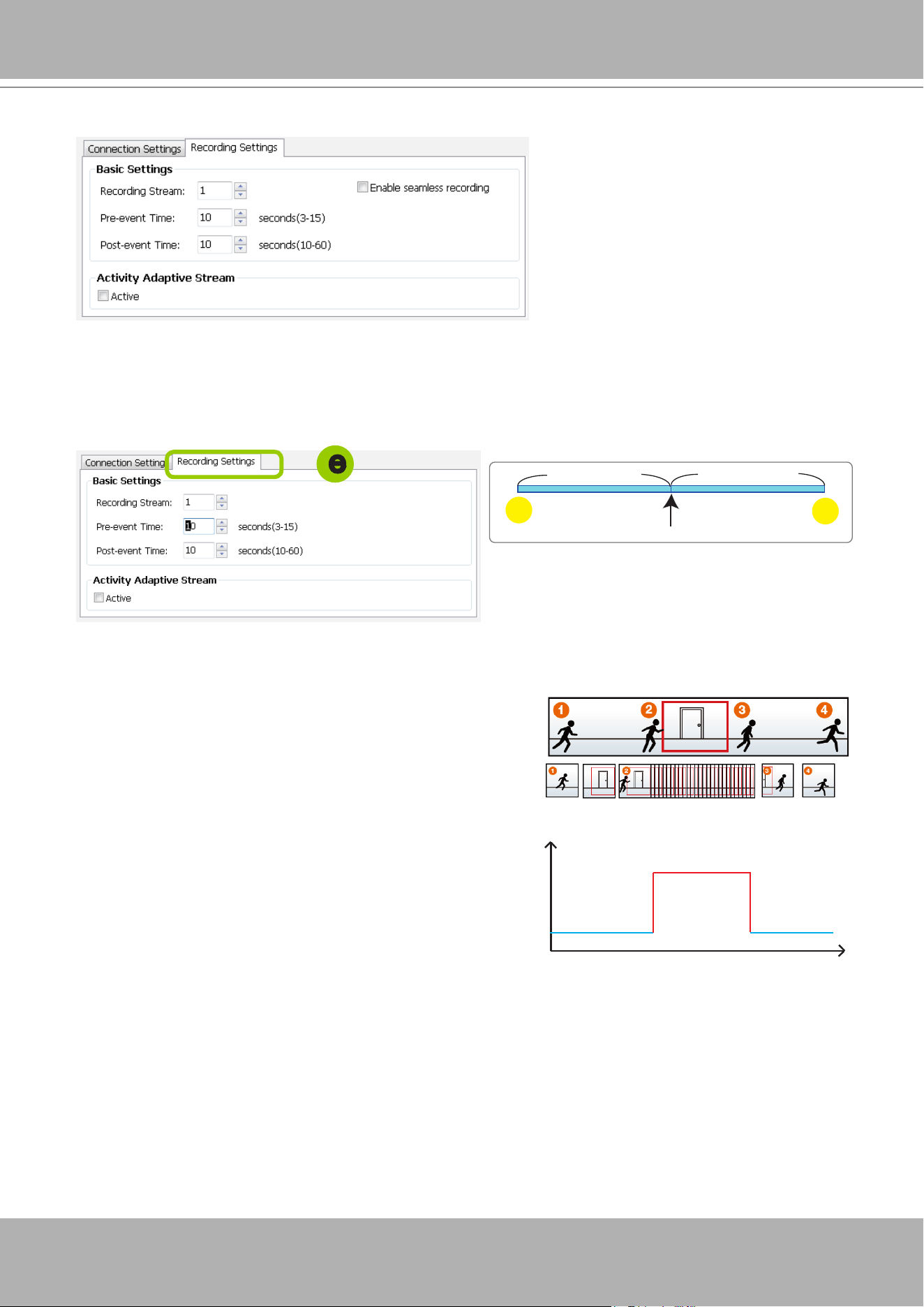
VIVOTEK - A Leading Provider of Multimedia Communication Solutions
User's Manual - 97
Recording Stream: By default, the stream source of the recording stream is stream 1, if you want to
change it later on, please refer to the previous page to update the camera settings (Update Camera).
Pre-event time: Enter a number to decide how much time to record before an event is triggered.
Post-event time: Enter a number to decide the duration of recording after an event is triggered.
For example: If both the Pre-event time and Post-event time are set to 10 seconds, a total of 20
seconds of video will be recorded if an event is triggered. This function is supported by the buffer area
on a VAST server.
Activity Adaptive Stream (active if possible): Check this
item to enable activity adaptive stream recording. For
cameras that come with multiple streams features, users
can make use of activity adaptive streaming for dynamic
frame control.
If you check Activate Activity Adaptive Stream, the VAST
server will record full-frame-rate video only when an
event is triggered on the camera; otherwise, it will only
request the I frame data during normal monitoring, thus
effectively save lots of bandwidths and storage.
Time
Bandwidth
Bandwidth
Activity Adaptive Streaming
for Dynamic Frame Rate Control
I frame ---> Full frame rate ---> I frame
Continuous recording
post-
10 sec.
pre-
10 sec.
Trigger Activation
Pre-event time
Post-event time
e
Note the following with the associated configuration:
The Pre-/Post-event time conguration only applies to
event recording.
The Activity Adaptive Stream (a.k.a., AAS) only applies to
the Continuous Recording.
e. Congure
Recording Settings
:
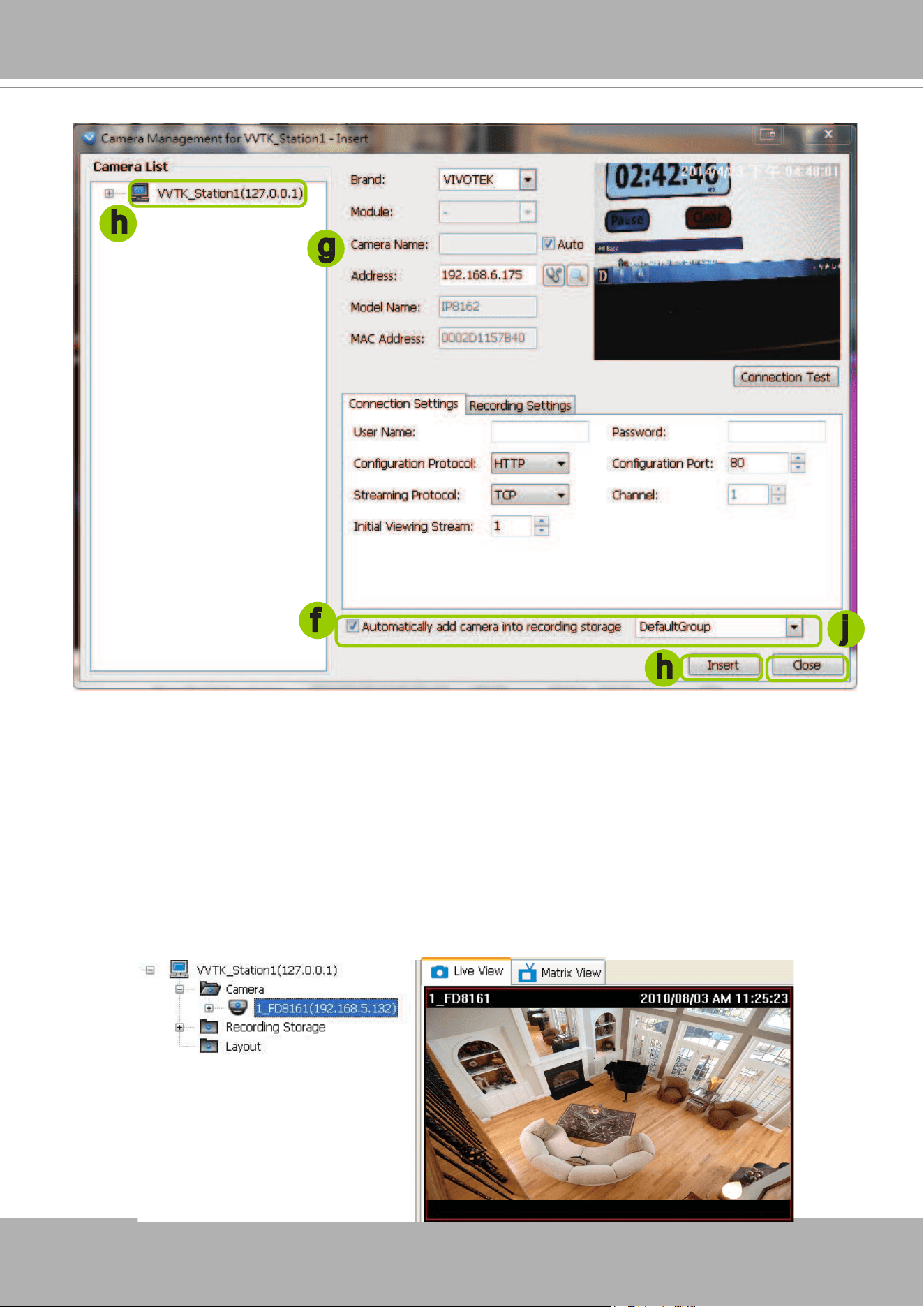
VIVOTEK - A Leading Provider of Multimedia Communication Solutions
98 - User's Manual
f. The device will automatically be assigned to the default recording group. Deselect the item if you want
to cancel this setting.
g. You can deselect the "Auto" checkbox behind the
Camera Name
entry, and manually enter a name
of your choice, such as "East alley bullet." This name will be used as the folder name for the recorded
video les. An index number will still be appended to the folder name. Note that if this name is changed
when the recording is taking place, the conguration change will not take effect until the next day.
h. When all settings are completed, click
Insert
to add the device to the station. The device will be
displayed under the Camera List on the left.
i. To insert additional devices to the station, repeat the above steps.
j. When completed, click
Close
to exit the camera management window.
k. Back to the main window, you will nd the newly-inserted devices displayed under the station and the
live video in the video cell.
f
h
j
h
g
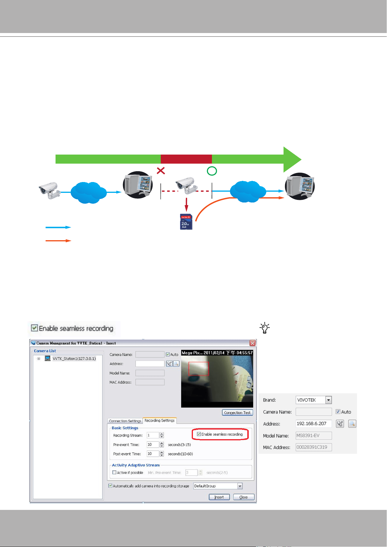
VIVOTEK - A Leading Provider of Multimedia Communication Solutions
User's Manual - 99
Seamless Recording
Seamless Recording safeguards critical videos in the occurences of network disconnection.
In the event of temporary disconnection, video is stored in individual cameras' SD/SDHC/
SDXC card; and once the connection is restored, a VAST server can automatically resumes the
recording. More remarkable is that, a VAST server can simultaneously retrieve the time-tagged
videos that were temporarily stored on SD/SDHC/SDXC cards. For information about the latest
rmware/software revisions that support this feature, please contact your sales representatives
or technical support.
The video data retrieved from SD/SDHC/SDXC card also include event-triggered recordings
such as pre- or post-event footages, if events were detected during the network outage.
VAST
Server Station
14:30 14:50
Disconnect Restored
Timeline
LAN/WAN
VAST
Server Station
LAN/WAN
1
4
:
3
0
~
1
4
:
5
0
Seamless Recording
SD/SDHC/SDXC
Normal recording
Retrieval
The Seamless Recording feature is enabled when inserting, updating, or batch inserting
cameras in the Camera Management window. The rmware/hadware compatibility of this
feature is automatically detected, i.e., this feature is not available when a non-compliant camera
is attached. If a compatible camera is attached, a checkbox will be available as shown below.
Tips
:
Try out the Detect model
button on the Insert Camera
page if the Seamless
Recording checkbox does not
appear.
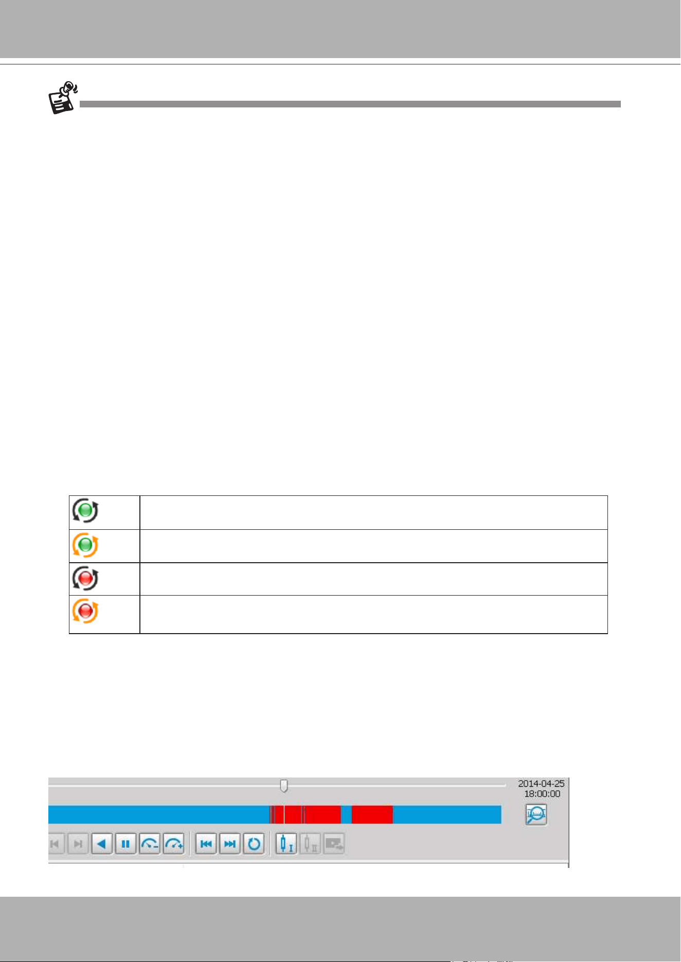
VIVOTEK - A Leading Provider of Multimedia Communication Solutions
100 - User's Manual
• When the SD/SDHC/SDXC card storage space is full, cameras will stop recording. When
the network conneciton between VAST server and cameras is restored, videos in the SD
card will be transmitted back to the VAST server. Note that the videos that were not recorded
during the time when the network was disconnected will not be transmitted.
• If the videos on the cameras belong to those that are about to be erased within 24 hours (e.g.,
for the lack of storage space on a VAST server), those videos will not be retrieved.
Limitations:
• Retrieving video fragments from a camera can momentarily double the throughput of normal
video streaming.
• Video streams recorded using the MJPEG codec is not supported by Seamless recording.
• Seamless recording can only take place from a camera with 1 video stream recorded to a
maximum of 3 VAST servers. .
Onscreen Elements for Seamless Recording:
• The associated icons will appear in the Liveview, popup window on e-Map, and the Matrix
view. The status icon appears on the upper right of the view cell.
• Below is the description of the Seamless recording statuses and the indicative icons.
Normally the video fragments will be retrieved rst, and then the event log:
Currently not recording video from camera, but is retrieving data from camera due to
previous disconnection.
Currently not recording video from camera, but is retrieving event log.
Currently recording video to system as well as retrieving data.
Currently recording video to system as well as retrieving event log.
After a period of time, the gaps of recording (those blue lines or blocks representing network
interruptions during the recording) should be gradually stitched up. It is, however, system
integrators' responsibility to build a reliable network. Additional bandwidth should also be
available for retrieving fragmented recordings from the camera side.
The VAST checks for the need for retrieving fragmented videos by every one minute. If the
retrieval failed due to some network faults, the server will re-try the retrieval tasks later on.
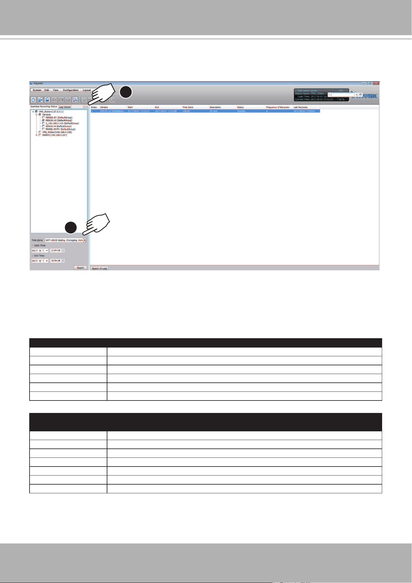
VIVOTEK - A Leading Provider of Multimedia Communication Solutions
User's Manual - 101
1
2
In the Playback utility, you can select the tabbed window on top of the device tree to select
"
Seamless Recording Status
." If, after a cable disconnection, you can select to check if the
Seamless recording has duly performed a recovery.
Note that when a cable is disconnected, the Seamless Recording Status may not immediately
display a disconnection event. The timeout for a disconnection is 1 minute, and the VAST server
and camera will take some time handling the disconnection and re-connection. Even you notice
the disconnection on live view, the Seamless Recording Status may take longer than 1 minute
to display the current status.
Status Description
Camera is Disconnected The connection between server and camera has not been restored.
Standby Standing by for recovery.
Recovering Recovering recording data from camera.
Revover failed Recovery errors occurred, and recovery failed.
Recover successfully Recovery success.
No Need to Recover No Need to Recover.
UI Elements
Item Description
Start time Beginning of a disconnection.
End time The end of a disconnection.
Time Zone Time zone of the disconnection event.
Description Length of the disconnection.
Status The handling status for the disconnection event.
Frequency of Recovery The attempts made to recover data.
Last Recovery The time the last attempt was made to recover.
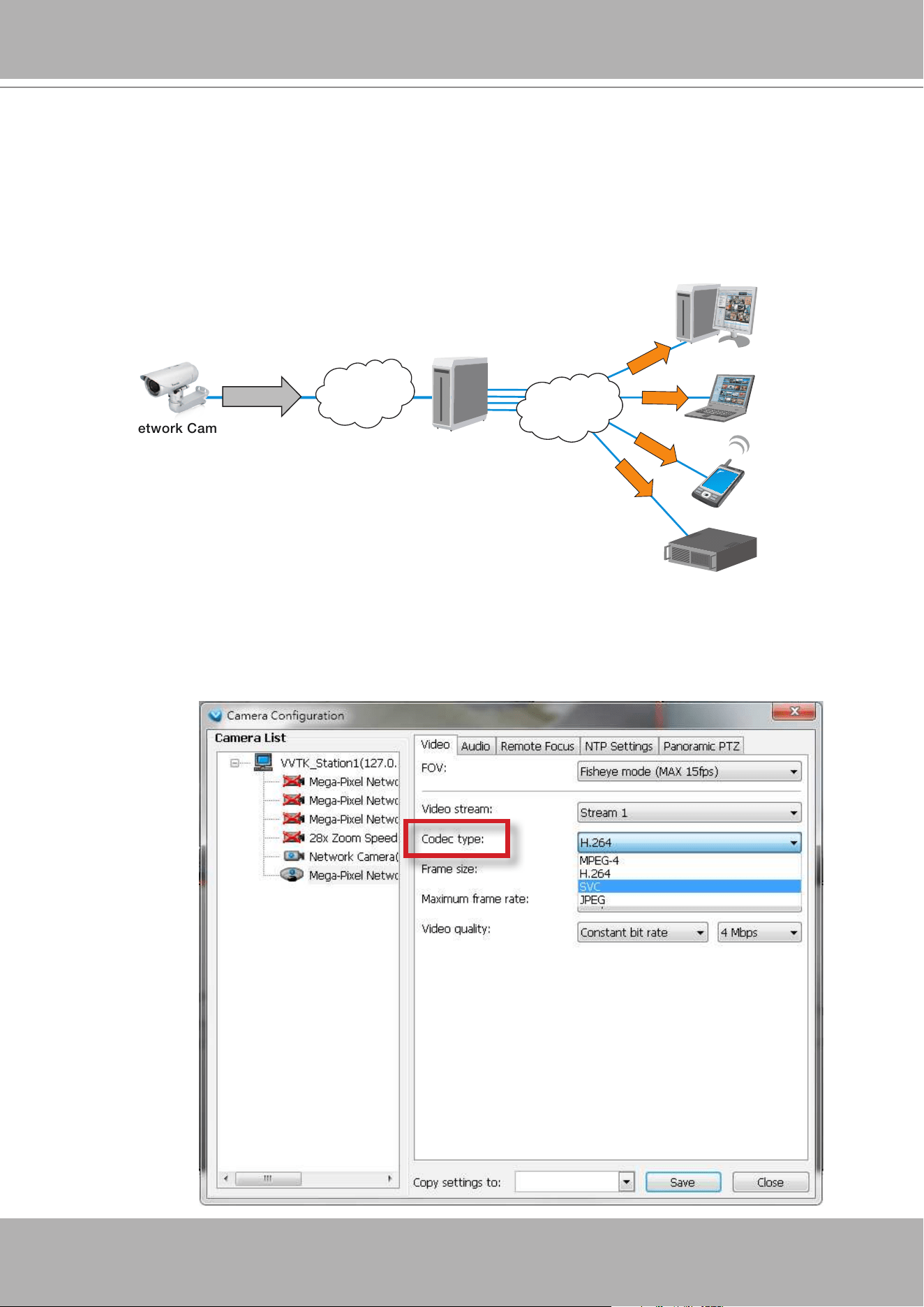
VIVOTEK - A Leading Provider of Multimedia Communication Solutions
102 - User's Manual
Enable SVC
If the camera to-be-added supports the latest SVC (Scalable Video Coding) feature, select the
SVC checkbox to enable the related control. The SVC feature enables streaming of videos for
multiple clients from one single set of layered IP packets. Designed for saving bandwidth and
CPU load on client stations, the frame rate of a video stream appearing through a view cell
can be individually adjusted. This feature applies when an administrator experiences unstable
video streaming due to the lack of network bandwidth, less-than-ideal hardware, or during an
occurence of network problems.
The VAST server (rev. 1.6.1 and later) automatically negotiates with a camera and determines
whether a network camera comes with the SVC feature.
To congure the SVC-related feature:
1. When inserting a new camera into your conguration, select the streaming option, usually the
stream #1.
VAST Server
Notebook
3G Cell Phone
Client PC
5fps
25fps
30fps
LAN
NVR Storage
60fps
LAN/WAN
SVC Packet
Stream
on Demand
Stream
on Demand
Stream
on Demand
Stream
on Demand
Network Camera
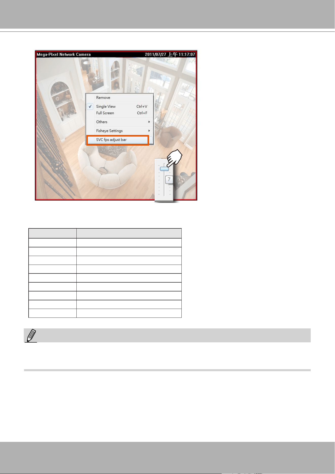
VIVOTEK - A Leading Provider of Multimedia Communication Solutions
User's Manual - 103
2.
Right-click on the view cell of an SVC-enabled camera. Select
SVC fps adjust bar
.
3. A slide bar will appear above the view cell. Click and drag the slide bar. A numeric indicator
will display the current selection. See below for the frame rates represented by the numeric
indicator.
Indicator Frames per second (fps)
Maximum 30
7 26
6 22
5 18
4 12
3 8
2 4
1 1
Minimum 1/4
NOTE:
The SVC feature only applies to H.264 and MJPEG streams. It is not applicable to MPEG-4 streams.
Please refer to Conguration -> Media -> Video for individaul stream settings.
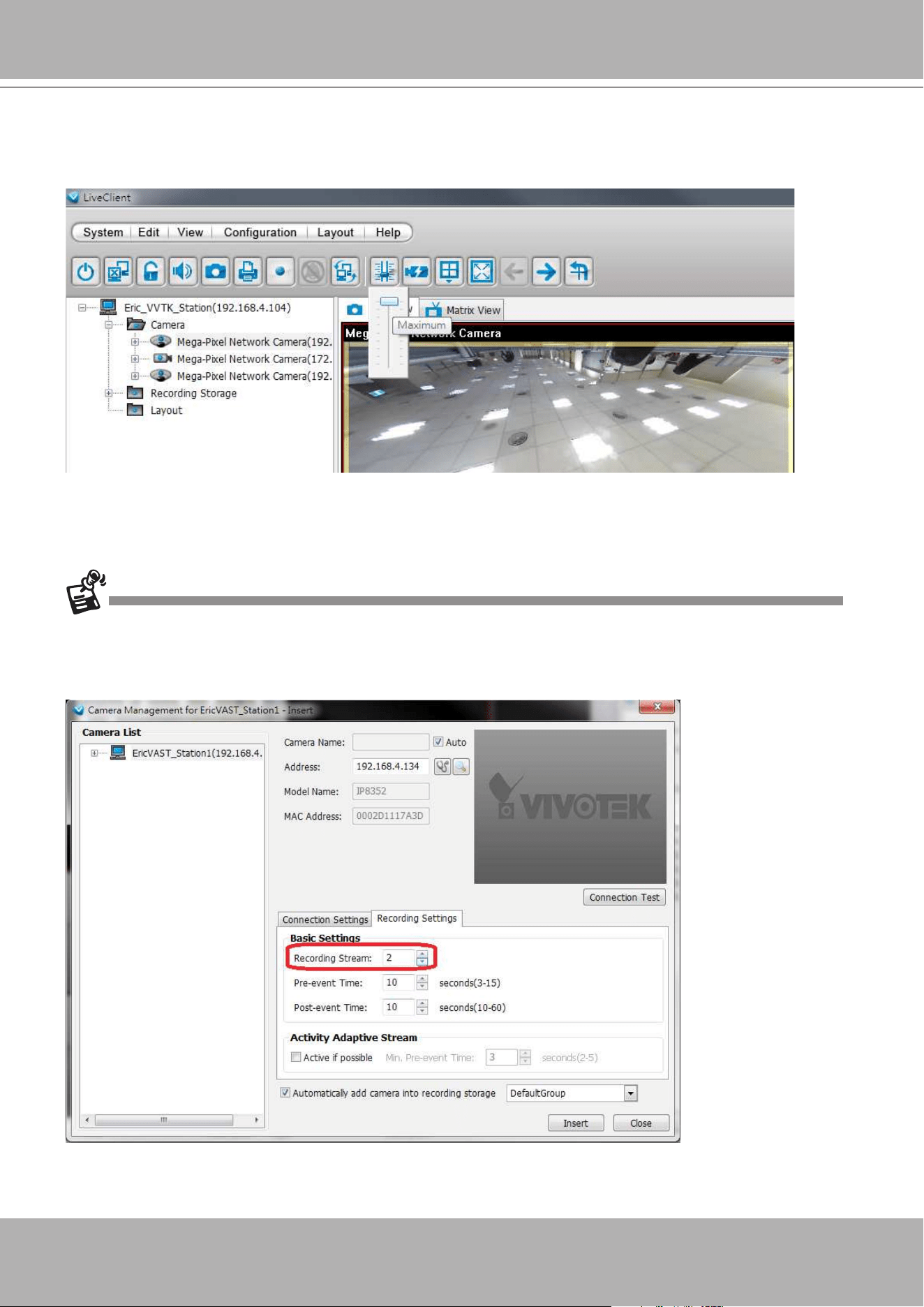
VIVOTEK - A Leading Provider of Multimedia Communication Solutions
104 - User's Manual
If you have multiple SVC-enabled cameras, you can enable a collective setting via the
Adjust
SVC level
button on the tool bar. The frame rate selected here will then apply to all view cells on
the VAST LiveClient console.
Please note that the SVC related setting can not take effect while the LiveClient station is
running the Layout Rotation. Stop the layout rotation before conguring the SVC function.
While you save your bandwidth for live viewing, you can still record full-frame-rate video by changing the
recording setting. For example, you can enable resource-saving SVC on stream #1 and congure stream
#2 to be recorded with full details, in terms of frame size, frame rate, and video quality.
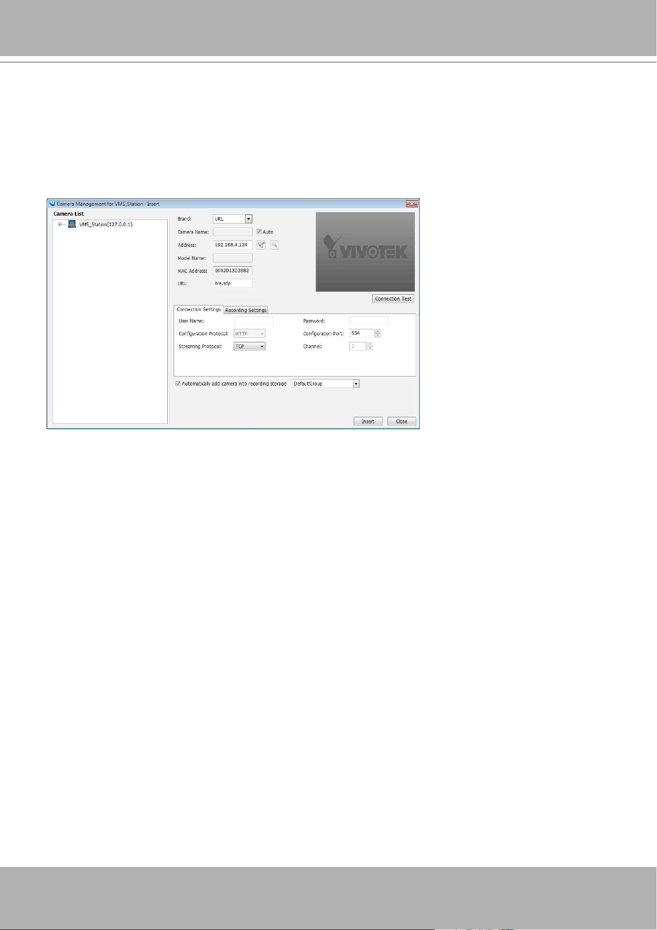
VIVOTEK - A Leading Provider of Multimedia Communication Solutions
User's Manual - 105
Streaming URL
You can enter a camera's IP address to add a camera's RTSP streaming for live view and
recording, and playback.
To insert a camera using the URL-like command,
1. Select the camera Brand as "URL."
2. Enter the camera's IP address.
3. Enter the camera's MAC address as printed on the camera label, or one found by the
Shepherd utility.
4. Enter "554" in the Conguration port.
5. Enter "live.sdp" in the URL field, as this is part of the original RTSP streaming command:
"rtsp://172.18.204.58:554/live.sdp". If streaming stream #2, enter live2.sdp.
Note that the free 32 channel licenses does not apply when inserting a camera using the
URL command. Only the live view, recording, and playback functions are supported if thus
connected. All other functions are not supported, such as auto streaming size or changing to
another video stream. Camera DI/DO is also not supported.
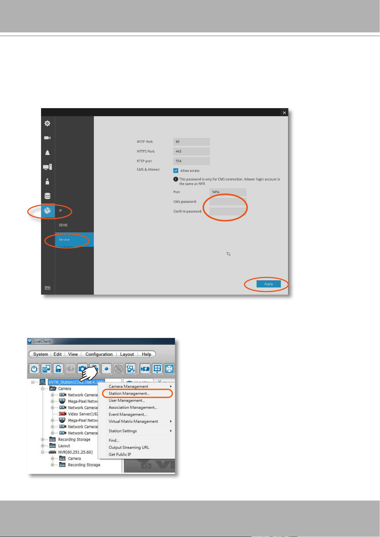
VIVOTEK - A Leading Provider of Multimedia Communication Solutions
106 - User's Manual
Insert NVR (Network Video Recorder)
1. Before you can include an NVR system into your current conguration, you should enable
the corresponding configuration on a web management console with the NVR system. In
Conguration > System > VAST
, click on the
Enabled
checkbox and enter a password for
authentication.
2. Return to your VAST management screen. Left-click to select your VAST station on the navigation
panel, and then right-click to display and select "Station Management..."
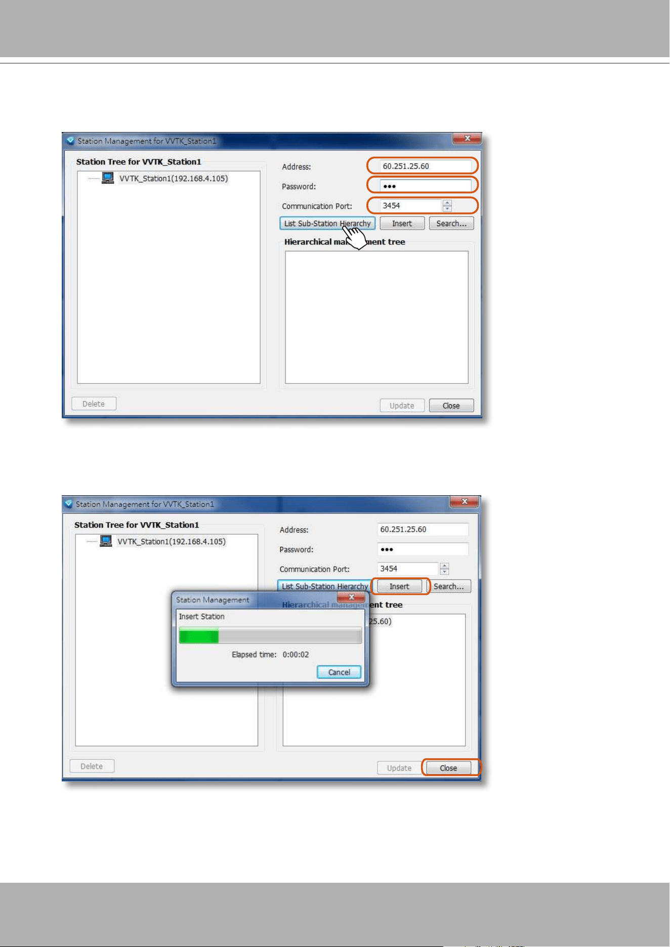
VIVOTEK - A Leading Provider of Multimedia Communication Solutions
User's Manual - 107
3. The Station Management window will prompt. Enter the
Address
,
Password
, and check if the
Communication Port
match that you set for the NVR. Click on the
List Sub-Station Hierarchy
button.
After a brief delay, the NVR server will be listed in the column. You may also use the
Search
button to locate similar devices if they are reacheable in your local area network.
4. You can then click the
Insert
button to add the NVR server to your configuration. When
done, click the
Close
button.
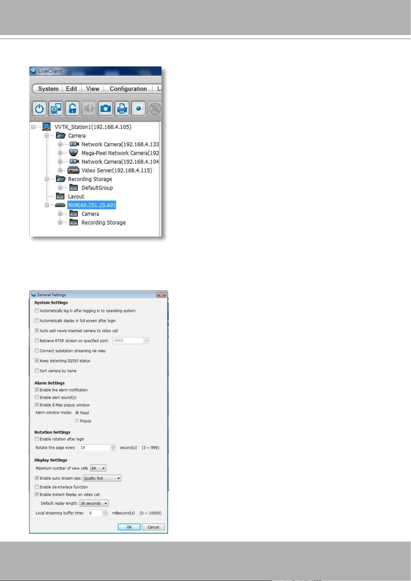
VIVOTEK - A Leading Provider of Multimedia Communication Solutions
108 - User's Manual
5. The NVR will appear in the navigation panel along with its subordinate cameras.
To enable the detection of NVR DI/DO signales,
1. Enter
Conguration
>
Client Settings
>
General Settings
. Select "
Keep detecting DI/DO status
."
Note that you should restart the VAST console for the conguration to take effect.
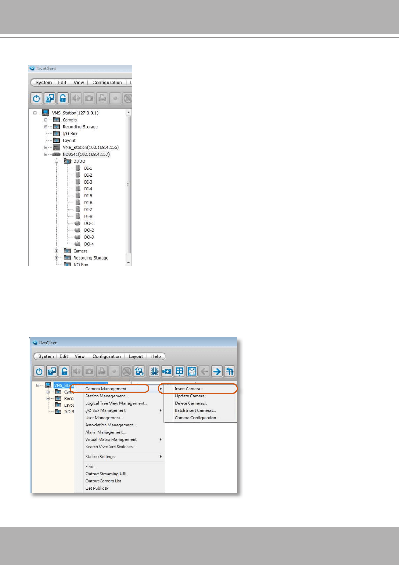
VIVOTEK - A Leading Provider of Multimedia Communication Solutions
User's Manual - 109
Insert a Video Server
1. Left-click on your VAST station, and then right-click to display the
Camera Management
command. Let your cursor stay on the command for a second and then move to the
Insert
Camera
command. Click on the command to open its conguration window.
The NVR's DIs and DOs will be listed on the device tree. Note that the DI/DO status is not supported by
NVRs running an embedded VAST software.
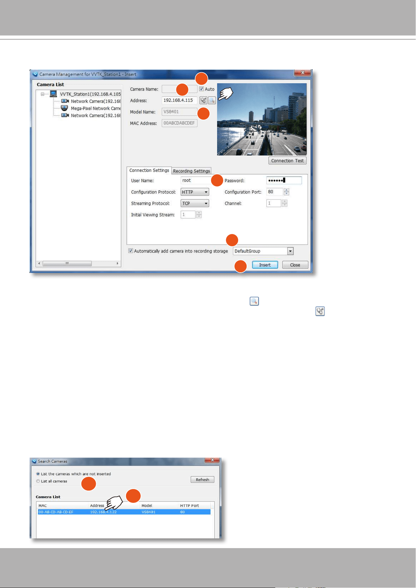
VIVOTEK - A Leading Provider of Multimedia Communication Solutions
110 - User's Manual
2. See below for the steps to insert a Video Server along with its subordinate cameras.
2-1. You can deselect the
Auto
checkbox to enter a name for the Video Server. If set to Auto and your
video server already has a name, that name will be displayed in your device list.
2-2. Enter the
Address
of the video server - or - use the
Search
button to open a Search window.
2-3. If you enter its address and it is found after you click on the
Detect Model
button, its
Model
Name
and
MAC Address
will be listed.
2-4. Before you click the Detect button, you should enter the
User Name
and
Password
for access
to the video server. You should also confirm the
Configuration Protocol
,
Configuration Port
,
Streaming Protocol
, and the rest of the networking parameters.
2-5. You may select or deselect the checkbox in front of the recording storage option - or - use the pull-
down menu to select the default group or a pre-congured storage group.
You might use the
Connection Test
button to verify if the stream comes from the device you prefer.
2-6. Click
Insert
to include the video server to your conguration.
The Video Server should now be listed on the Camera List.
You can also use the
Search
button to poll the local area network for VIVOTEK's devices. You can
select to list all cameras or list those that have not been included in your current conguration.
Click on a device, and its detailed information will immediately appear in the
Camera Managemen
t
window on the left. For recording settings, please refer to page 97 as previously described.
1
2
3
4
5
6
1
2
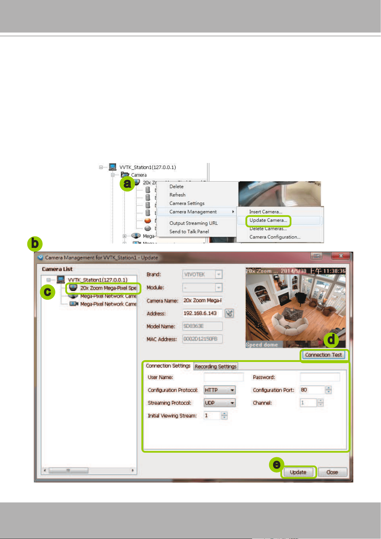
VIVOTEK - A Leading Provider of Multimedia Communication Solutions
User's Manual - 111
Update Devices
Please follow the steps below to update a device via Camera Management window:
a. Click
Conguration > Camera Management
> Update Camera
on the menu bar (or
right-click
the
device/station, then select
Camera Management > Update Camera
).
b. The
Camera Management - Update
window will pop up. The device tree managed by the station will
be displayed in the left Camera List window.
c. Select a device from the list you want to update. Its related information will automatically be displayed
in the corresponding fields in the Camera Management window. Then you can modify
Connection
Settings
and
Recording Settings
of the device.
d. After modifying the settings, you can click
Connection Test
to preview the live video from the device.
e. When all settings are completed, click
Update
to enable the settings.
b
c
e
d
a
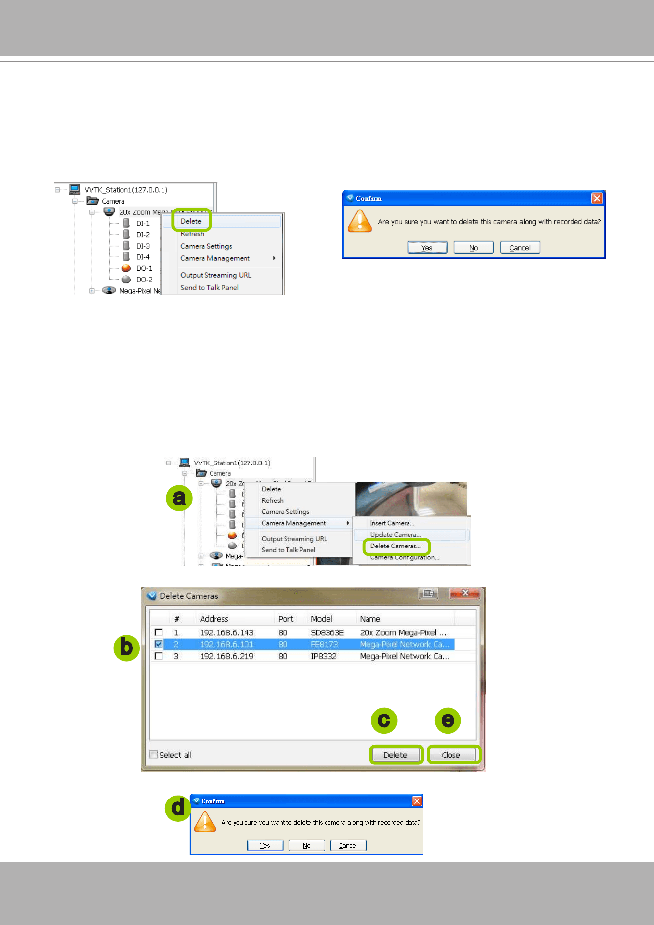
VIVOTEK - A Leading Provider of Multimedia Communication Solutions
112 - User's Manual
Delete Devices from the VAST Server
Delete a device:
Right-click
the device on the device tree, then select
Delete.
A dialog box will pop up. Click
Yes
to
delete the device along with the recorded data; click
No
to delete the device but retain the recorded
data; click
Cancel
to cancel the delete action.
Delete more than one device at a time:
a. Click
Conguration > Camera Management
> Delete Cameras
on the menu bar (or
right-click
the
device/station, then select
Camera Management > Delete Cameras
).
b. The
Delete Cameras
window will pop up.
c. Select the devices you want to delete from the list, then click
Delete
.
d. A dialog box will pop up. Click
Yes
to delete the device along with the recorded data; click
No
to delete
the device but retain the recorded data; click
Cancel
to cancel the delete action.
e. When completed, click
Close
to exit the
Delete Cameras
window and return to the main window. The
deleted device will disappear from the station.
b
a
c
d
e
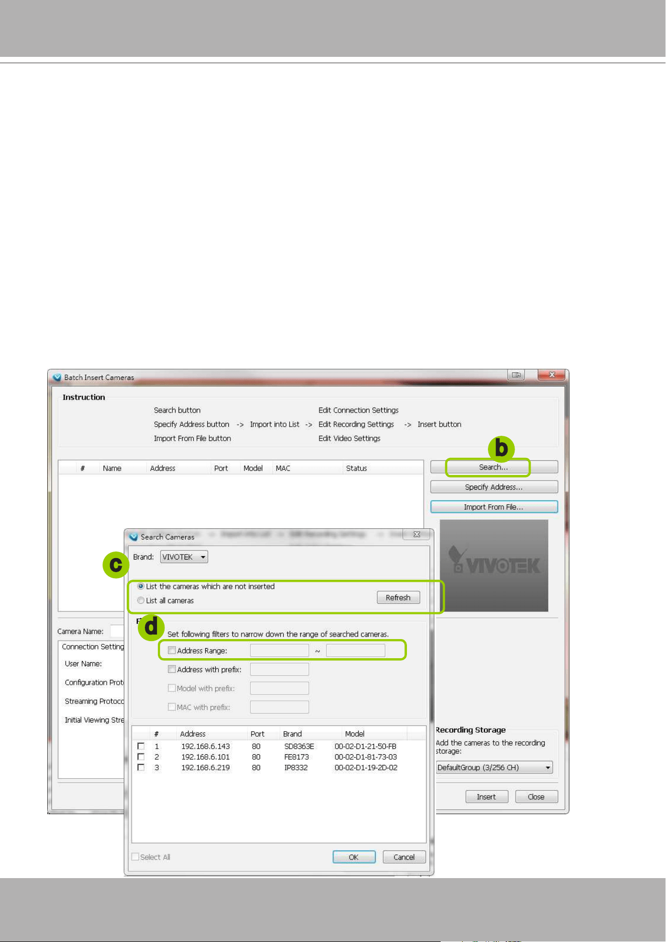
VIVOTEK - A Leading Provider of Multimedia Communication Solutions
User's Manual - 113
Batch Insert Devices
Batch insert is a very useful function that allows user to search, filter, and import a row of
devices that are in the same LAN to a VAST station. The basic settings can also be applied to
those inserted devices simultaneously, e.g., a common user name and password.
Please follow the steps below to batch insert devices to a station:
a. Click
Conguration > Camera Management
> Batch Insert Cameras
on the menu bar (or
right-
click
the station, then select
Camera Management > Batch Insert Camera
).
b. The
Batch Insert Cameras
window will pop up. Then click
Search
to open the Search Camera
window.
c. On top of the Camera List window, you can select "List the cameras which are not inserted" or "List
all cameras". The items listed below will then change accordingly. You may select ONVIF-compliant
cameras as well using the Brand selector.
d. Use the 4 Filters to narrow down the range of the wanted cameras from the list.
IP Range: Type in a range of IP address to narrow down the list; the lter automatically applies after
you ll in a correct IP range.
b
c
d
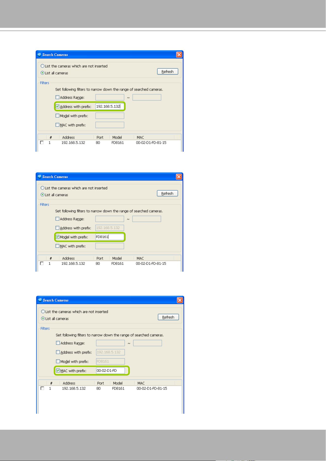
VIVOTEK - A Leading Provider of Multimedia Communication Solutions
114 - User's Manual
IP with prex: Type in the prex of the IP address to narrow down the list.
Model with prex: The user can type in the prex of the model name or the complete model name of
the cameras to narrow down the list.
MAC with prex: You can type in the prex of the MAC address of the cameras to narrow down the
list.
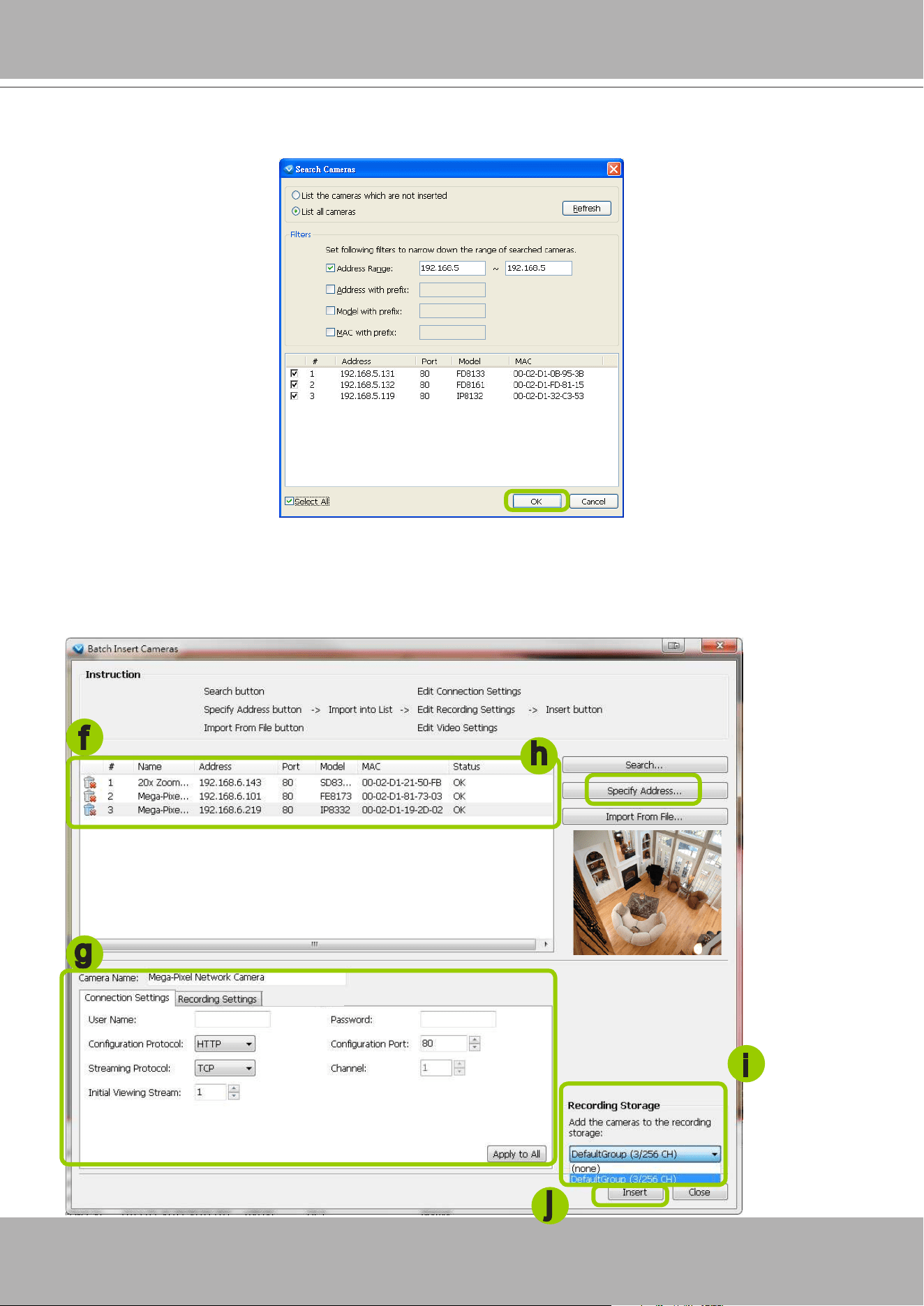
VIVOTEK - A Leading Provider of Multimedia Communication Solutions
User's Manual - 115
e. When the list is ltered, you can select the cameras one by one or check
Select All
to add them to the
batch insert list. Then click
OK
to nish searching.
f. The selected cameras will be shown on the batch insert camera list with the camera information and
the connection status. When you click on a camera, a live view will show up on the right side for you to
identify the cameras on the list. If you want to remove a camera from the list, click the trash can icon to
delete it.
g
f
h
j
i
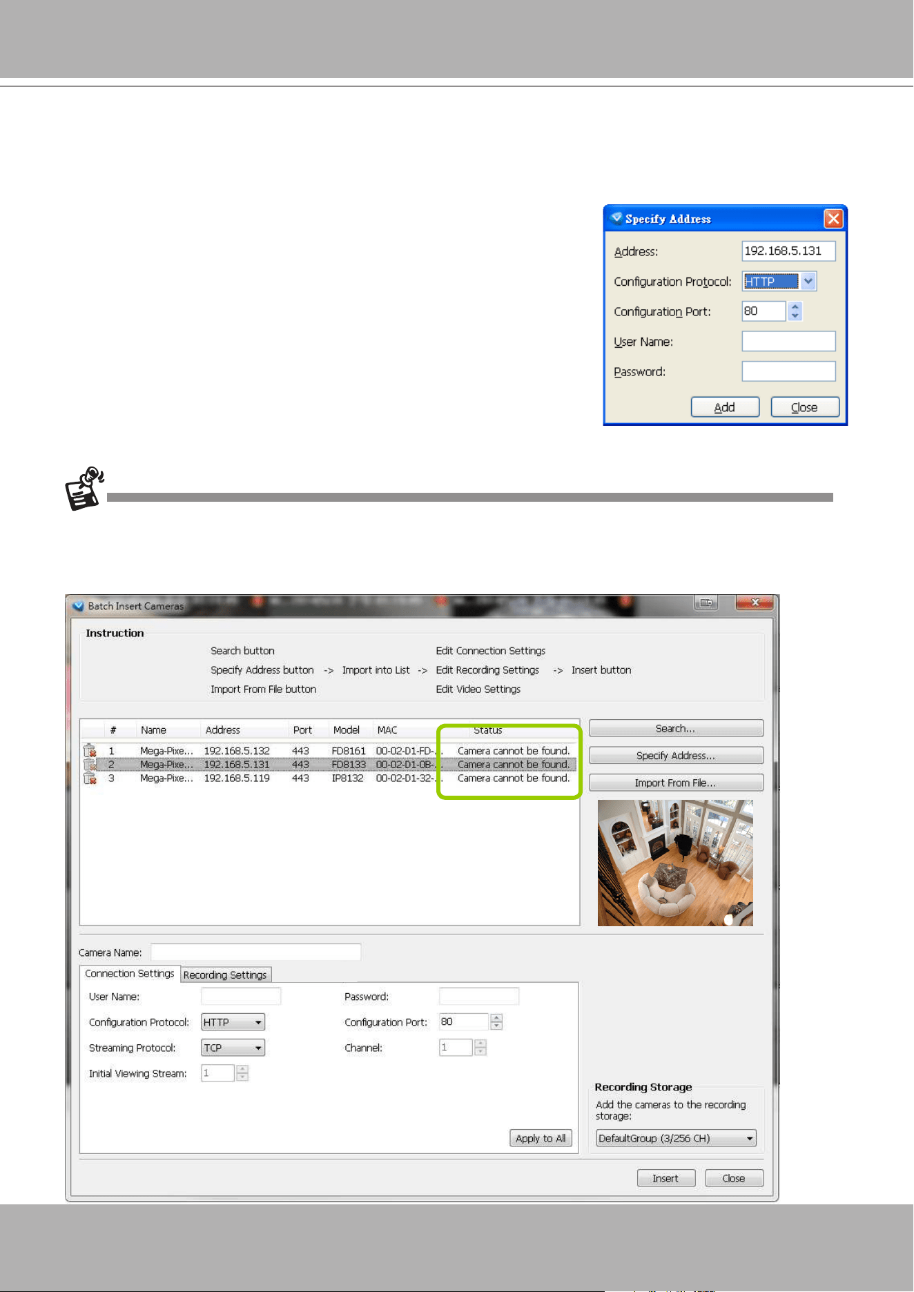
VIVOTEK - A Leading Provider of Multimedia Communication Solutions
116 - User's Manual
g. At the bottom of the window, there is a eld for you to alter the camera settings including Connection
Settings and Recording Settings. You can apply the new settings to each camera on the list, or
click
Apply to All
to apply the same congurations to all the cameras. For more information about
Connection Settings and Recording Settings, please refer to Insert Device on page 95 for detailed
information.
When you modify the camera settings, and when the connection information (User Name, Password, Conguration
Protocol, Conguration Port, and Streaming Protocol) does not match the current network environment, the camera
will be disconnected and the status of the camera will become “Camera cannot be found” as shown below.
h. Specify host: If you want to add a camera to the list, click
Specify
Address
to directly add a wanted camera. Click
Add
after lling in
the correct information. The camera will be added to the list of the
Batch Insert Camera window.
i. By default, all inserted devices will be applied to the default
recording group. Deselect the
Add
checkbox if you do not want to
assign the selected devices to the default recording group.
j. Click
Insert
when all the settings are done. Cameras will be added.

VIVOTEK - A Leading Provider of Multimedia Communication Solutions
User's Manual - 117
You can enter a User name and Password and use the Apply to All button to apply this combination
to all selected cameras. This way, you do not need to change the user name and password for every
individual cameras.
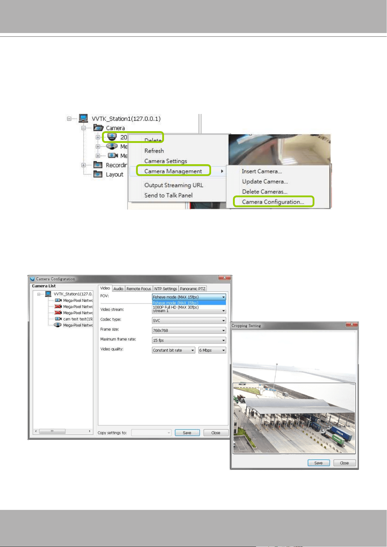
VIVOTEK - A Leading Provider of Multimedia Communication Solutions
118 - User's Manual
Camera Conguration
The
Camera Conguration
function group provides immediate access to the video streaming
and other settings without the need to open a web console. The function group is accessed by
selecting a camera on the device tree, and right-click to select
Camera Management
>
Camera
Configuration
. If you have new VIVOTEK cameras and the VAST server can not recognize
their features, see page 83 for how to update camera information using the Device Pack update.
FOV (Field of View)
The FOV configuration is available for 5 megapixel cameras (such as IP8372 and IP8172P),
which allows you to crop a portion of the image captured by the sensor. The FOV setting ap-
plies in the scenario where you do not need all of the video a camera can capture. For example,
when shooting a parking lot where the upper half of the image is the sky. Cropping a field of
view can help save bandwidth and reduce the requirements for storage space.
Video mode
For cameras having resource limitations such as hav-
ing a lower frame rate when supporting dual streams, or
lower frame rate when using the Rotation mode, its vid-
eo mode is automatically displayed in the Video window.
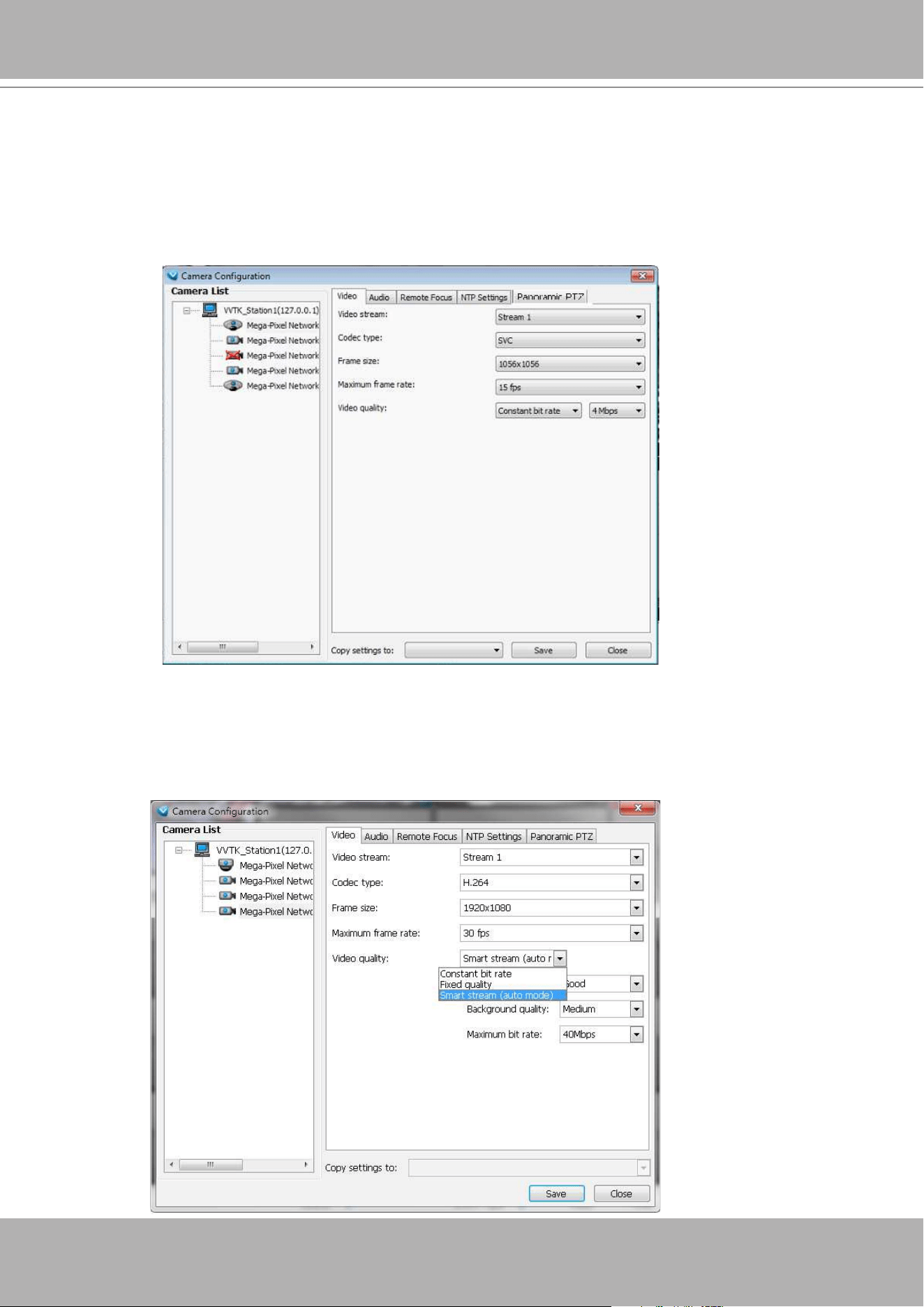
VIVOTEK - A Leading Provider of Multimedia Communication Solutions
User's Manual - 119
Video
This tabbed window privides access to the selection of the live view stream, its compression co-
dec, frame size, max. frame rate, and video quality. Note that the
Constant Bit Rate
methodol-
ogy can be used to ensure that the size of video stream does not exceed a preferred threshold,
regardless of the complexity or the changes of pixels in the image. You should use a maximum
of 1080P as
frame size
and 6Mbps as
constant bit rate
for video streams managed by this
system.
If your camera supports the
Smart Stream
function, the related options will be available with the
Video quality. Note that only the
Auto mode
option will be available.
Auto: When set to Auto, only the moving objects and the areas around them will be displayed
with the Foreground quality. The rest of the screen will be displayed with the Background (lower)
quality.
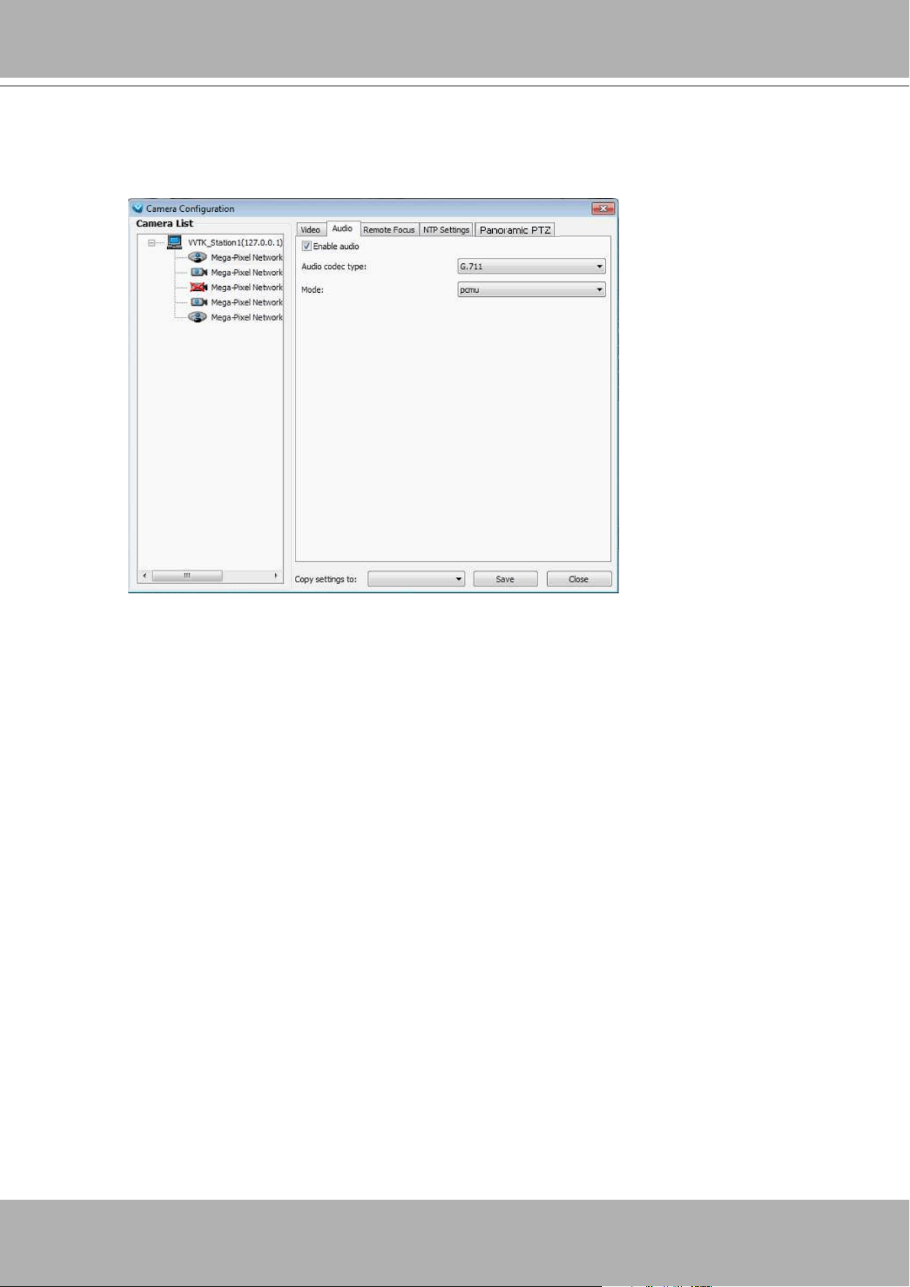
VIVOTEK - A Leading Provider of Multimedia Communication Solutions
120 - User's Manual
Audio
If audio feed is preferred, configure the audio codec type, sampling bit rate, and operating mode
in here.
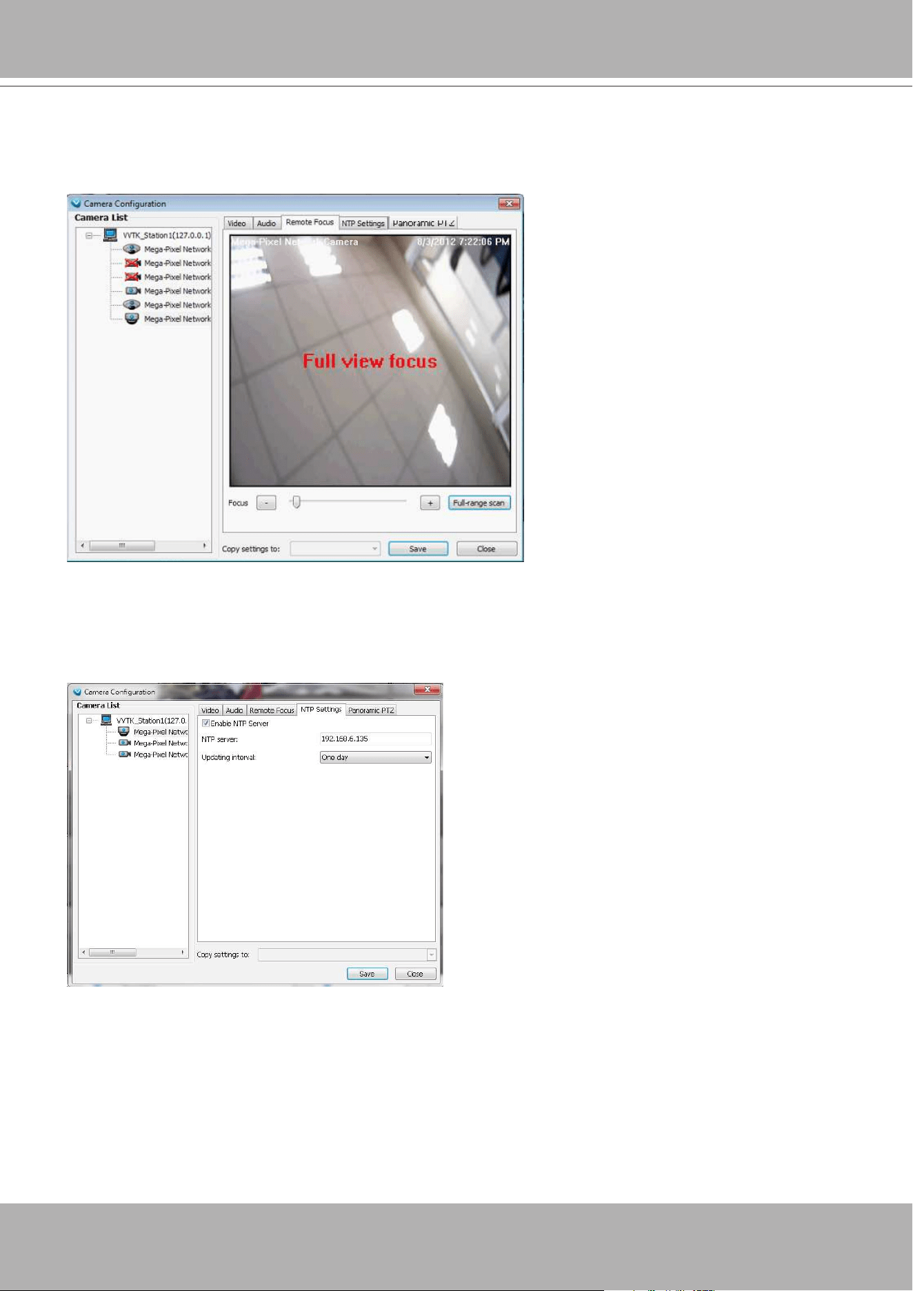
VIVOTEK - A Leading Provider of Multimedia Communication Solutions
User's Manual - 121
Remote Focus
For cameras supporting the remote focus feature, such as the FD8362E that comes with a motorized
lens, this window provides finetune buttons and full-range scan fucntion to help reach the best image fo-
cus.
Always remember to
Save
your configuration before leaving this window. You can also use the “
Copy
settings to”
button below to duplicate your current settings to adjacent cameras.
NTP Settings
If cameras’ real time clocks are set to be synchronized with a time server, enter the NTP server’s ad-
dress or domain name and specify an Updating interval. If you select the “Synchronize camera time with
system automatically” checkbox during the initial setup, the NTP server IP will be the VAST server’s IP.
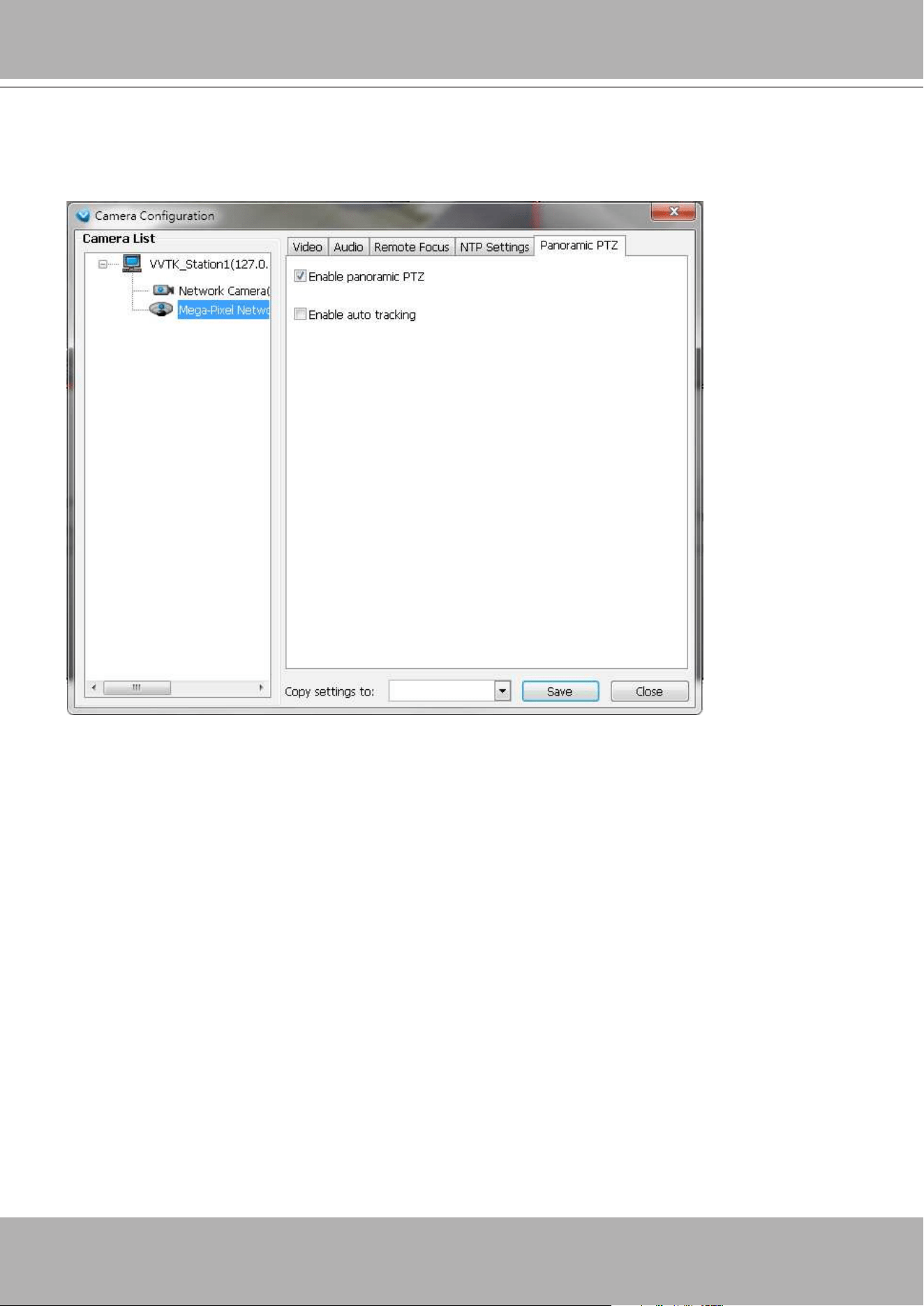
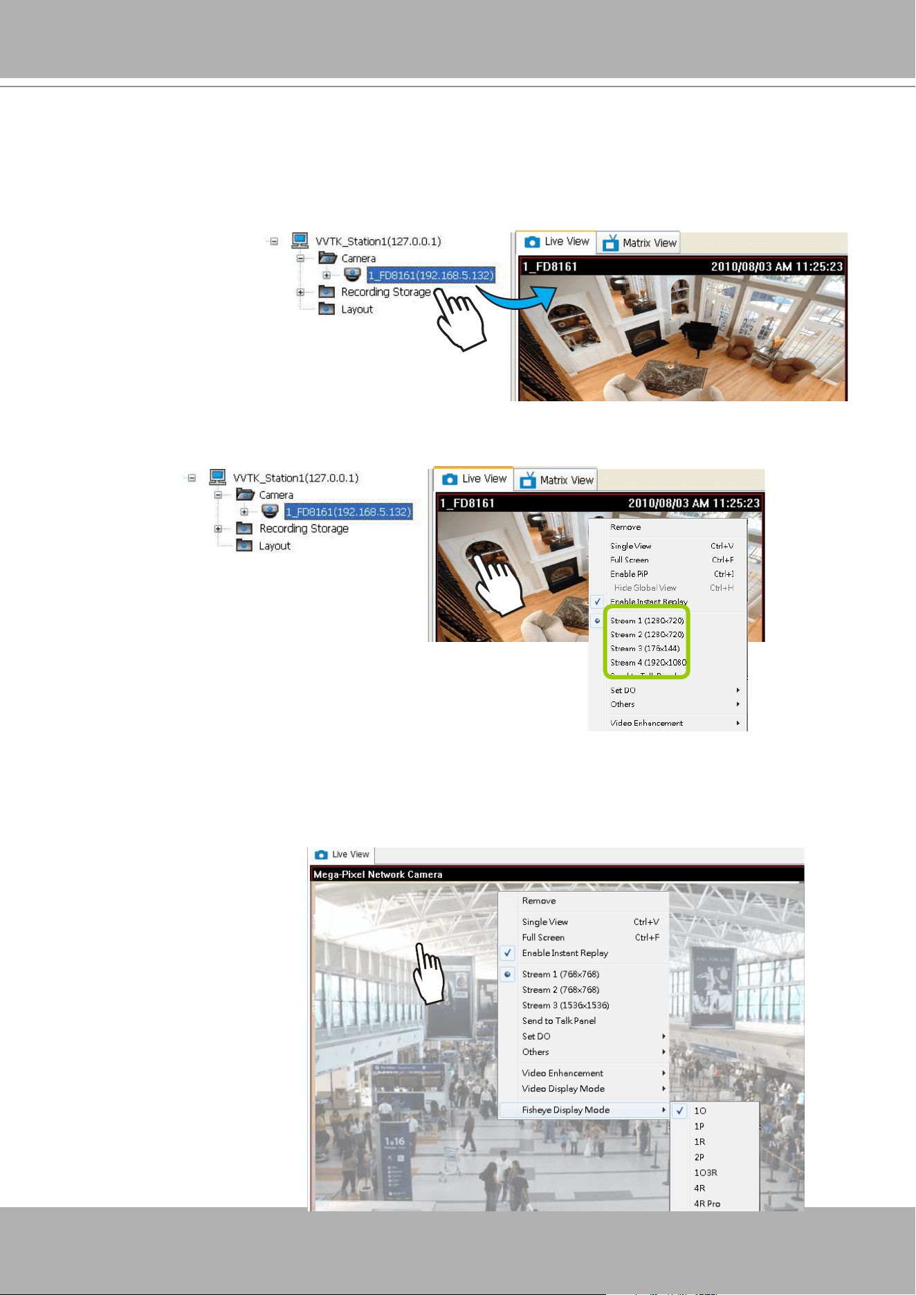
VIVOTEK - A Leading Provider of Multimedia Communication Solutions
User's Manual - 123
View Live Videos
The server will automatically add a newly-inserted device to the video cell for live viewing.
You also can
double-click
the target device or
drag-and-drop
the target device from the
hierarchical management tree to the video cell.
Dual / Multiple Streams
For dual-stream devices, you can
right-click
on the focused cell to select stream 1 or stream 2. For
multiple-stream devices, you can select from stream 1 ~ stream 4.
Fisheye Display Modes
By default, a circular view is displayed when a fisheye camera is successfully connected. To
display Regional, Panoramic, or the combination of different views,
right-click
on a fisheye
camera's live view to display the associated commands. The display modes available are: 1O
(Original), 1P (Panoramic), 1R (Regional), 2P (2 Panoramic), 1O3R (1 Original & 3 Regional),
4R (Quad Regional), 1O8R (1 Original & 8 Regional), and 4R Pro (4 Proactive) modes.
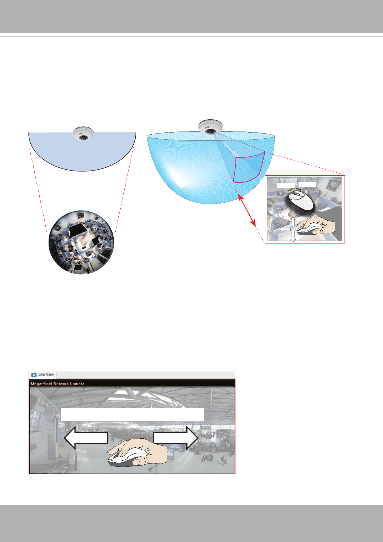
VIVOTEK - A Leading Provider of Multimedia Communication Solutions
124 - User's Manual
Fisheye Display Modes
: below are conceptual drawings for different display modes.
1O View (Original View)
180° Hemispheric
1R View (Single Regional View)
Zoom in/out
&
all-direction
navigation control
Zoom In
Zoom Out
An
Original
oval view covers the
hemisphere taken by the sheye lens.
A
Regional
view crops a portion of the hemisphere
as a region of interest. You can zoom in or out or
move the view area elsewhere from on the regional
view.
Swipe to scroll horizontally
1P
(Single
Panoramic
) Display mode:
With image correction algorithms in rmware, the hemispheric image is transformed into a
rectilinear stripe in the 1P display mode. Viewers can use the PTZ panel or simply use mouse
control to quickly move through the 360º panoramic view.
Note that the 1P view is apt for an overview, the Zoom in/out function does not apply in this
mode.
A Regional view is dewarped, by correcting images
from the distorted oval view to a rectangular and
visually proportional image.
1O
(Single Original) Display mode:
1R
(Single Regional) Display mode:
1P (Panoramic) Mode Screen Control
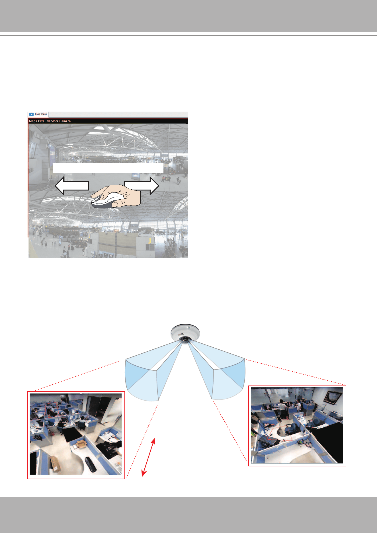
VIVOTEK - A Leading Provider of Multimedia Communication Solutions
User's Manual - 125
Swipe to scroll horizontally
2P
(2 Panoramic) Display mode:
Two dewarped rectangular views are placed one on top of another each showing 180 degree of
panoramic view. The 2P view looks like the upper view shows the front of hemisphere, and the
lower view the rear half of the hemisphere.
Zoom in/out
&
all-direction
navigation control
* Only two regional views are shown for simplicity reason
Fisheye cameras also support the display of multiple regional views taken from within the same
hemisphere, and they can be displayed with or without an Original view in its view cell.
3R View (Regional View)
1O3R
(One Original & 3 Regional) Display mode:
2P (Panoramic) Mode Screen Control
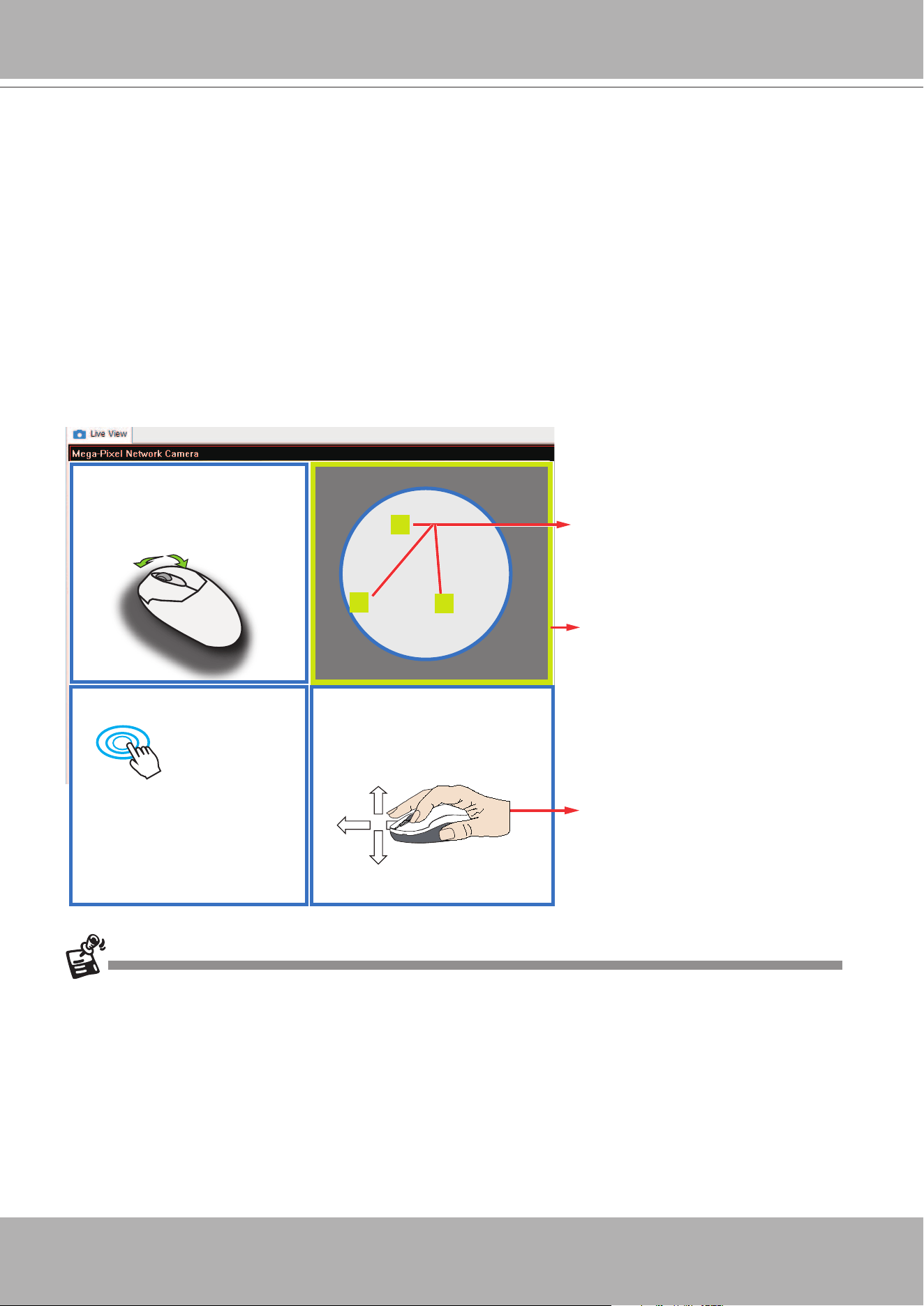
VIVOTEK - A Leading Provider of Multimedia Communication Solutions
126 - User's Manual
The various display modes require the support of D3D technologies by your display card on the
LiveClient or Playback station. Most off-the-shelf display cards today support this feature.
The onscreen mouse control is very agile. Therefore, use the PTZ panel for more delicate
moves in a field of view.
Pan
and
Patrol
moves are also supported if you have configured
preset PTZ positions in the camera's firmware. Note that the Pan move takes place in the
Panoramic and Regional views, while the Patrol function through preset positions applies only in
the Regional views.
PTZ Mouse Control
The "Mount type" setting also determines the display modes available to your display modes.
Please refer to sheye camera's User Manual for more information.
A highly versatile mouse control is implemented with sheye cameras. The same control takes
effect on a browser management session, on the LiveClient utility, and even on a video playback
screen. See the drawing below for how it works.
You can click and hold down the left mouse button to quickly swipe through the eld of view,
change the view angle, or use the mouse wheel to zoom in/out on a region of interest. However,
the PTZ mouse control is only available in the
"R" (Regional) mode
. In the
Panoramic mode
,
you can only scroll horizontally across the 180º or 360º panoramic view.
Current screen selection
Zoom In
Zoom Out
Click to bring into
center of view
Pan or tilt
1
2
3
Interactive
regional FOV indicators
Click and hold down
the button
1O3R (Original & Regional) Mode Screen Control
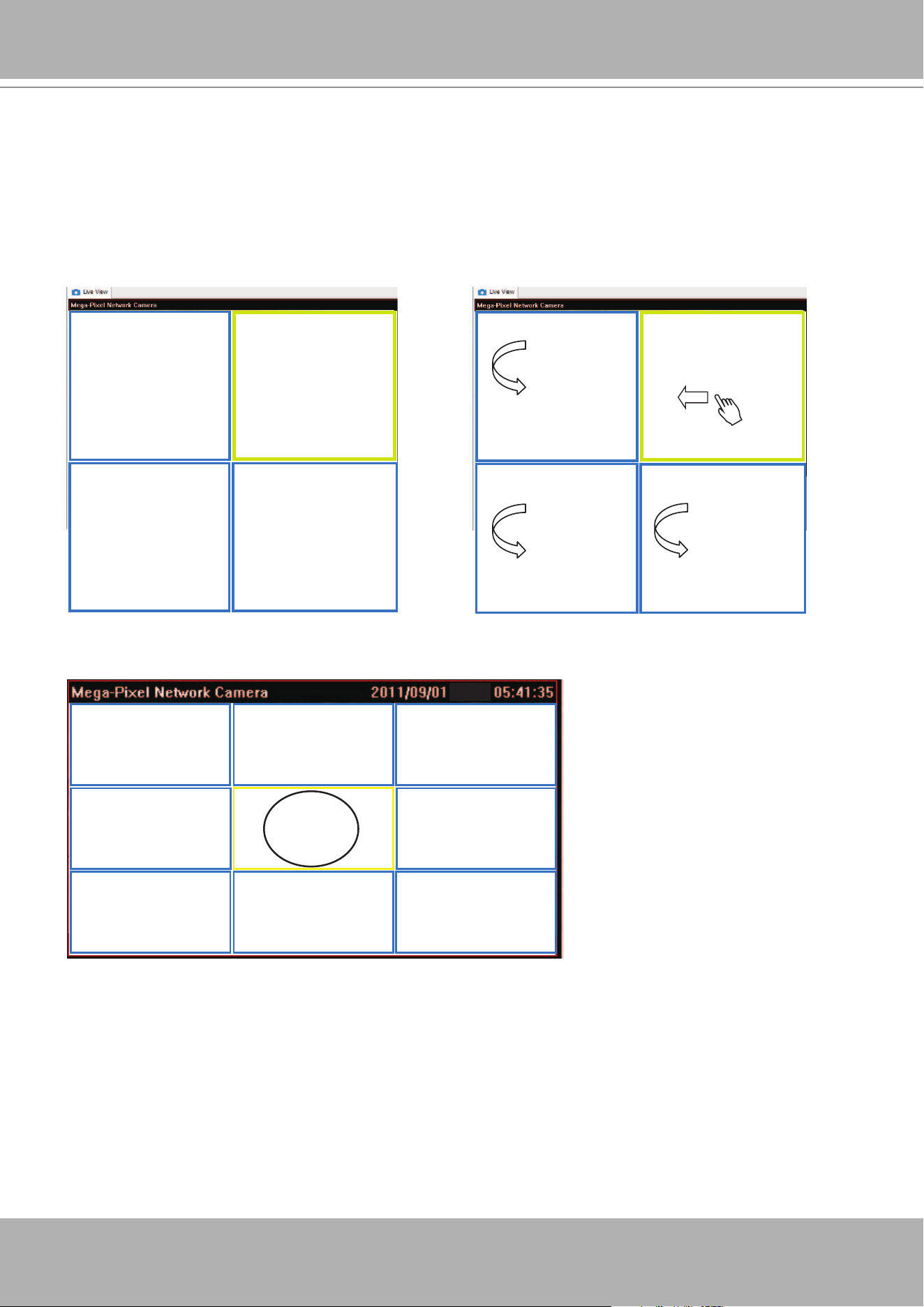
VIVOTEK - A Leading Provider of Multimedia Communication Solutions
User's Manual - 127
Regional View #1
Regional View #3
Regional View #2
Regional View #4
Regional View #1Regional View #2
Original View
Regional View #3
Regional View #6Regional View #5 Regional View #7
Regional View #4 Regional View #8
Regional View #1
Regional View #3
Regional View #2
Regional View #4
Below are the conceptual drawings for other display modes. The available display modes can
different with different mount types:
Regular: 1O, 1P, 1R, 1O3R, 4R.
Wall mount: 1P2R, 1P3R.
For more information, you can refer to sheye camera's user documents.
4R
(Quad Regional) Display mode:
1O8R
(One Original & 8 Regional) Display mode:
4RPro
(4 Regional Proactive) Display mode:
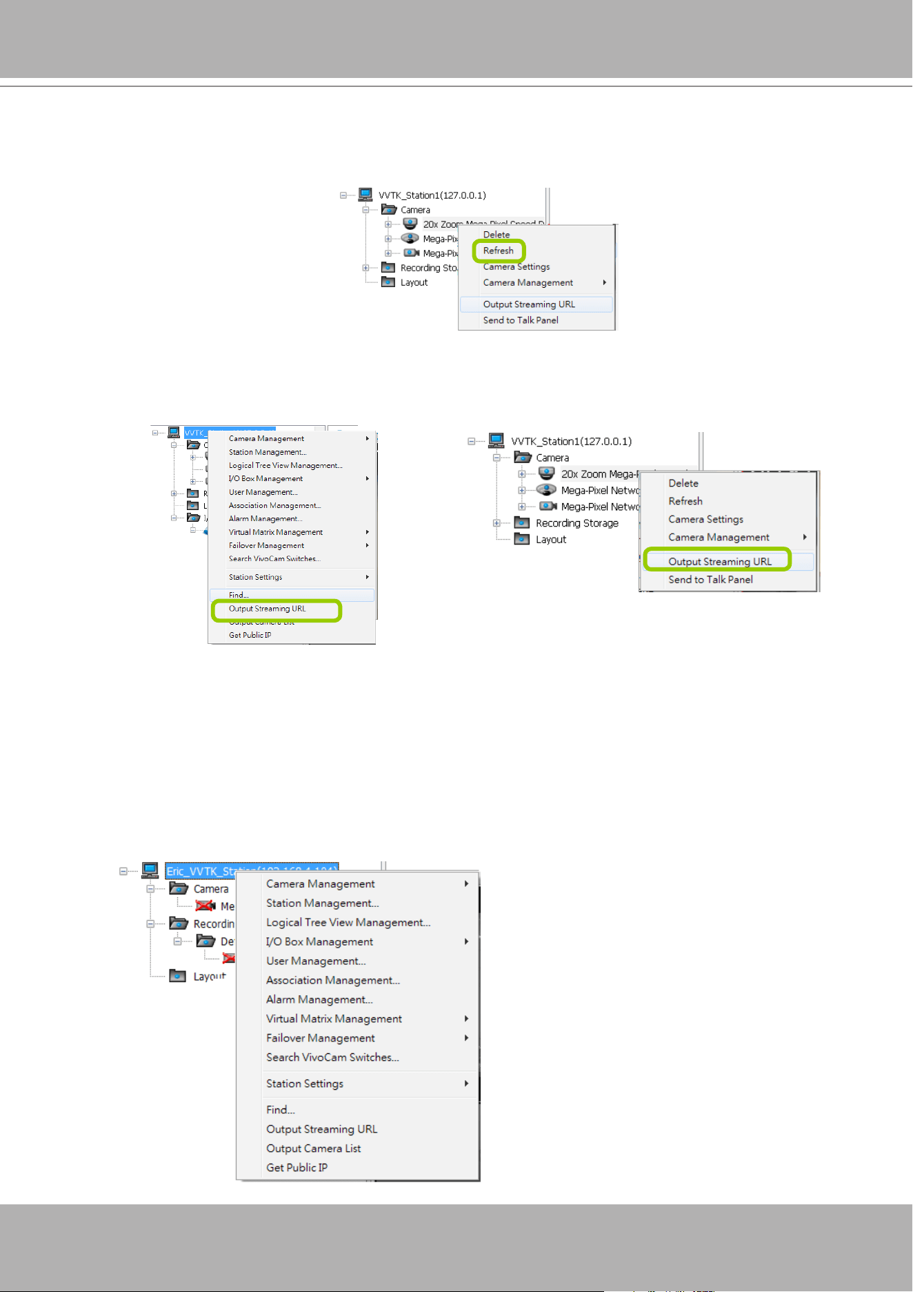
VIVOTEK - A Leading Provider of Multimedia Communication Solutions
128 - User's Manual
Refresh
Right-click
the device, then click
Refresh
, the camera information will be refreshed from the server.
Streaming Server
Right-click
the station or the device and click
Output Streaming URL
. A .txt le with streaming URL will
pop up. Then you can use this URL to link to the live streaming through QuickTime Player.
Get Public IP
If your access to Internet is via PPPoE, this function will display the public IP provided by your service
provider. If your access to Internet is via a router, please consult your network administrator or consult
your ISP for a valid public IP.
Output Camera List
This command produces a text file containing cameras' brand name, IP address, and HTTP port
information. The camera list le can later be used for Batch Insert function, Import from File.
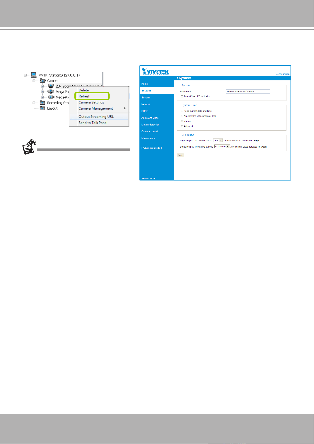
VIVOTEK - A Leading Provider of Multimedia Communication Solutions
User's Manual - 129
Camera Settings
Left-click
to select a camera,
Right-click,
and then click
Camera Settings
to open a brower's session
to the camera.
You must have an IE browser rev. 7.0
or above for opening a management
session.
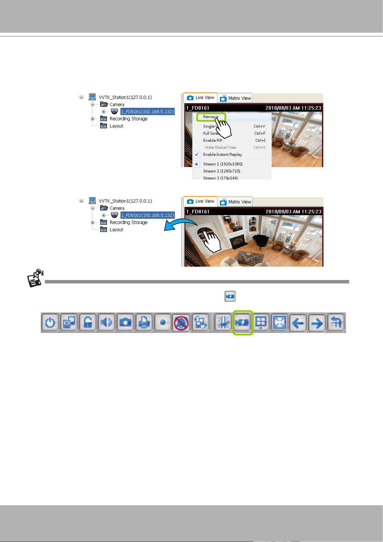
VIVOTEK - A Leading Provider of Multimedia Communication Solutions
130 - User's Manual
Remove Live Video from the Video Monitoring Window
There are two ways to remove a live video from the video cell:
Method 1.
Right-click
the video cell and select
Remove
.
Method 2.
Drag-and-drop
the live view from the video cell to the hierarchical management tree window.
If you want to remove all live videos from the video cells, please click on the menu bar.
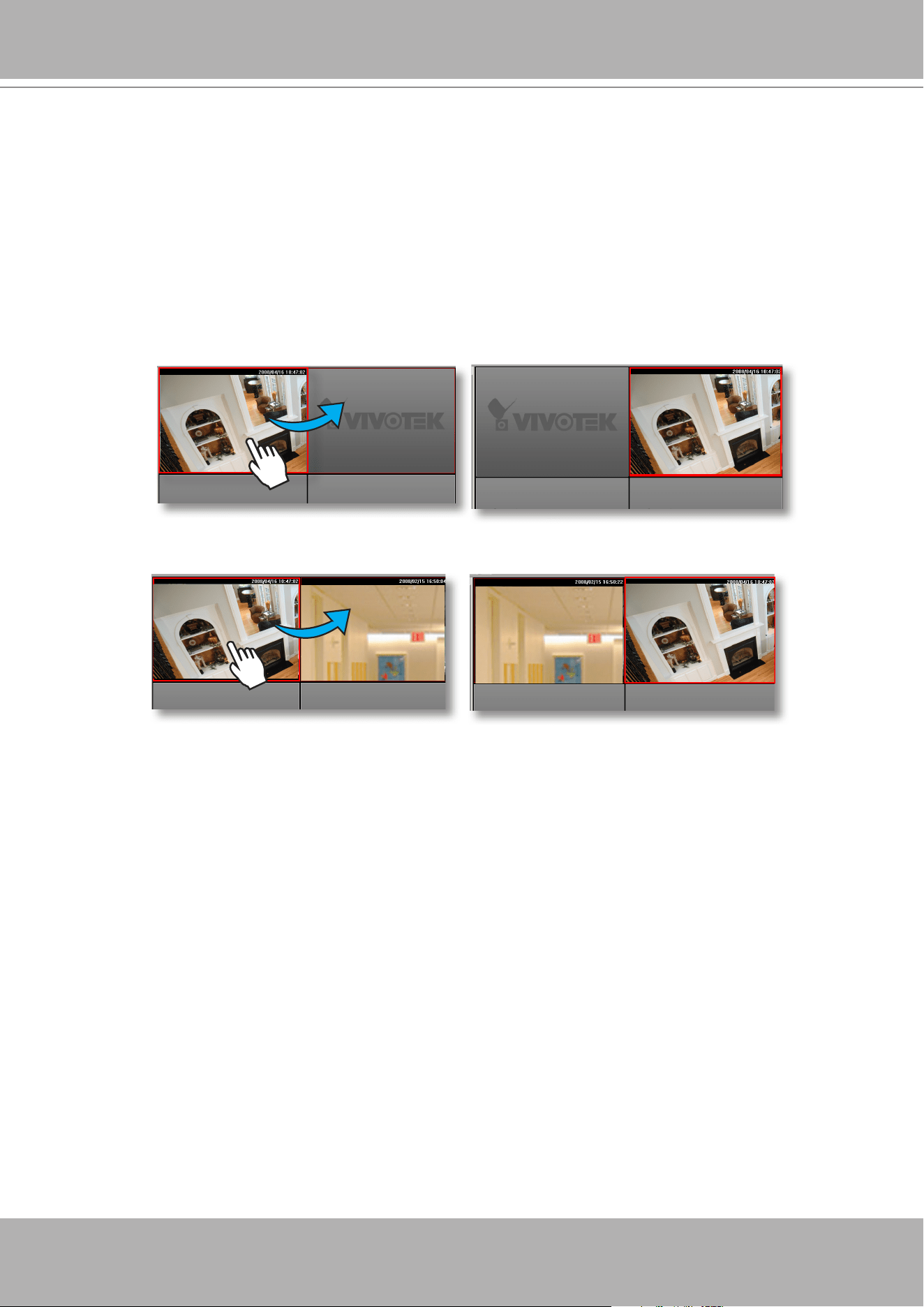
VIVOTEK - A Leading Provider of Multimedia Communication Solutions
User's Manual - 131
How to Change the VAST LiveClient Layout
Changing the Layout of the Live Video Monitoring Window
VIVOTEK VAST LiveClient supports up to 32-CH simultaneous video viewing on a single
monitor and allows you to change the layout of the live video monitoring window based on the
number of inserted devices.
Switch Video Channels
To move a video channel to another empty video cell,
drag-and-drop
the view to the target video cell.
To switch two different channels,
drag-and-drop
one view to the other, then the two different channels
will be switched to the opposite.
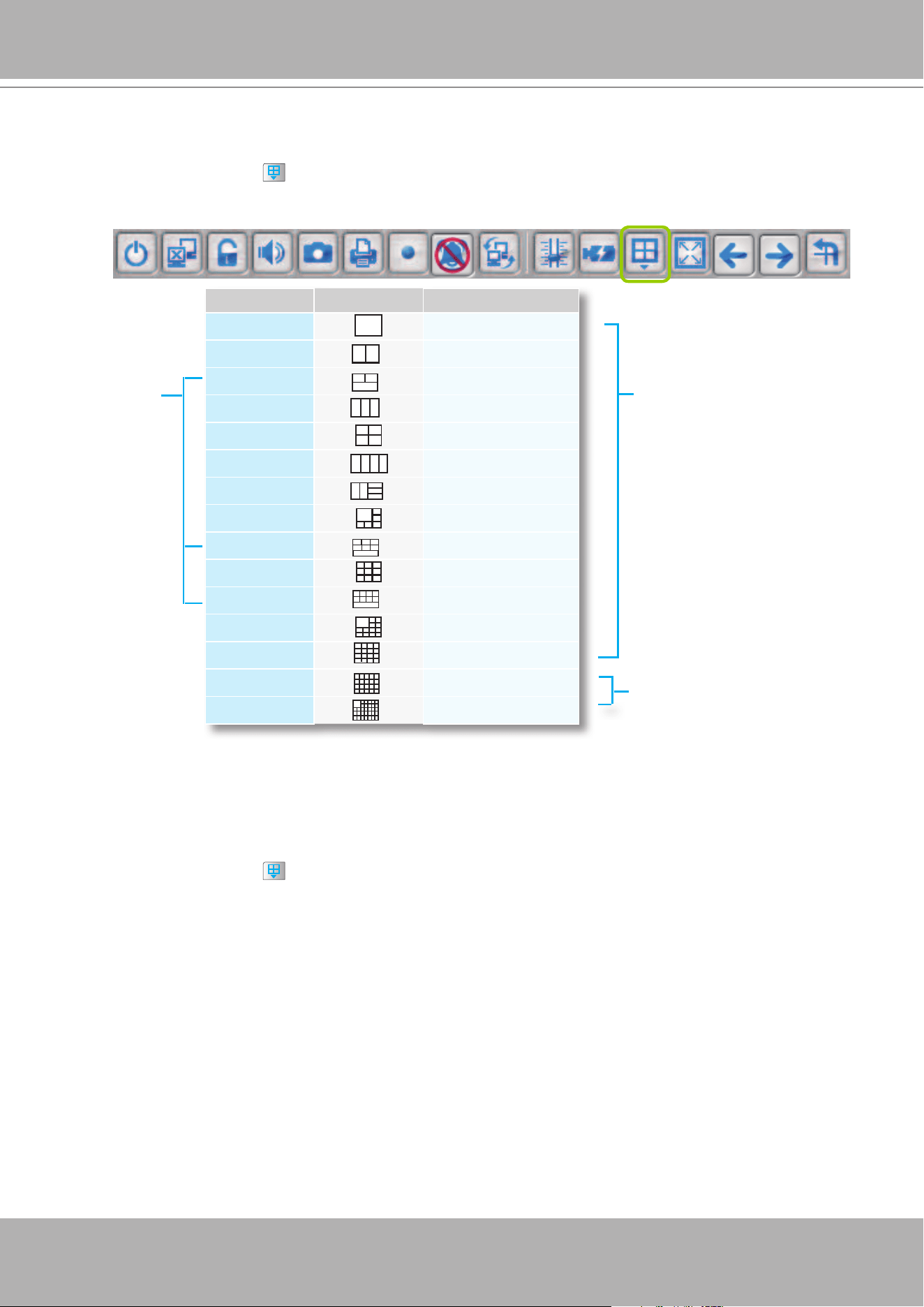
VIVOTEK - A Leading Provider of Multimedia Communication Solutions
132 - User's Manual
Congure Layout Mode
Click the
Layout
button on the quick access bar. Select a desired layout mode, and the layout
window will be changed accordingly. Below we illustrate 15 types of layout modes and the corresponding
page numbers:
Layout mode Description No. of Video page
1 x 1
32
2V
16
1P+2
20
3V
11
2 x 2
8
4V
8
2V+3
7
1 + 5
4
1P+6
8
3 x 3
3
1P+8
6
1 + 12
2
4 x 4
2
5 x 5
1
1 + 31
1
More than 1 video page;
rotation function is enabled
Only 1 video page;
rotation function is disabled
P-PTZ modes
Congure Layout Mode
Click the
Layout
button on the quick access bar. Select a desired layout mode, and the layout
window will be changed accordingly. Below we illustrate 11 types of layout modes and the corresponding
page numbers:
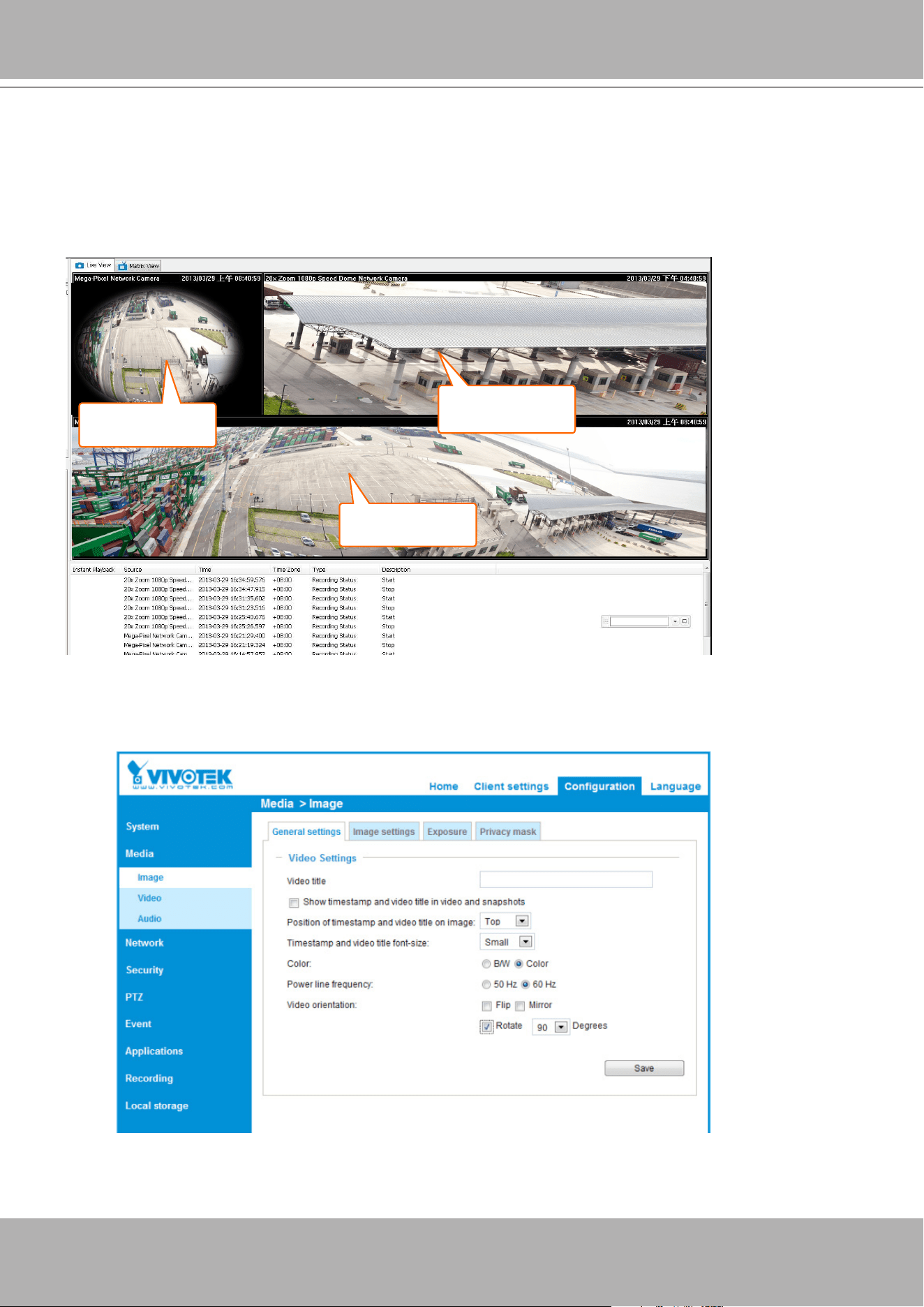
VIVOTEK - A Leading Provider of Multimedia Communication Solutions
User's Manual - 133
Some layout modes (1x1, 2V, 3V, 2x2, 4V, 2V+3, 1+5, 3x3, 1+12, 4x4) will spread all video channels
into several pages. Some cameras support the video Rotation function for scenarios such as a tall, long
corridor or the inside of a vehicle. The Rotation conguration is made through a web console with such
cameras.
The 1P+2, 1P+6, and 1P+8 layouts apply exclusively to the Panoramic PTZ congurations. Please refer
to page 324,
Appendix B Panoramic PTZ Conguration,
for details.
Normally, a Panoramic PTZ layout will consist of 1 sheye Original view, 1 speed dome eld of view, and
1 sheye Panoramic view as shown below. Note that the interactive click-on-image control only takes
place on the Original and the Panoramic views.
Fisheye
panoramic view
Fisheye Original
view
Speed dome
view window
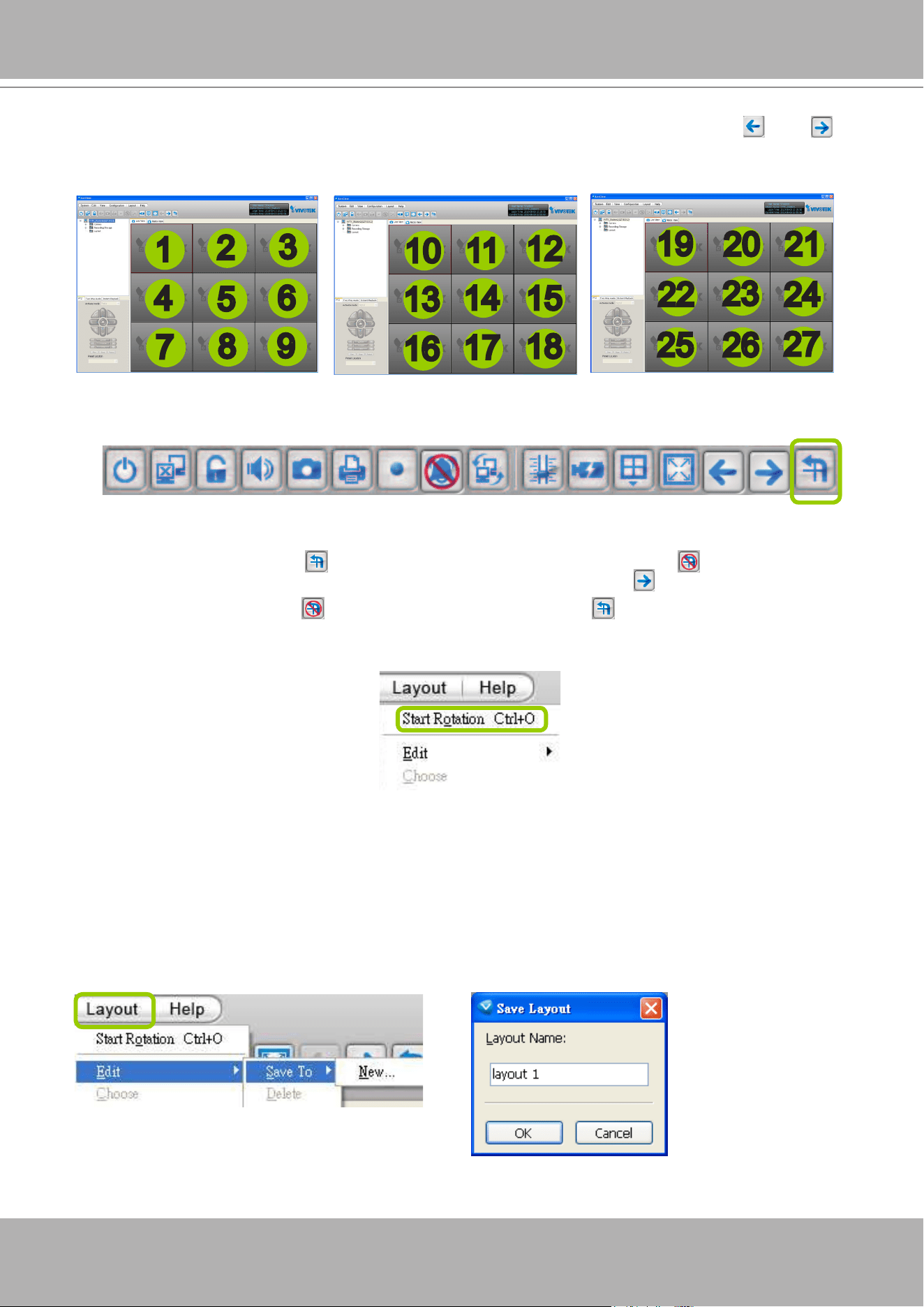
VIVOTEK - A Leading Provider of Multimedia Communication Solutions
134 - User's Manual
For example, under the 3x3 layout mode, you can switch among the pages by clicking and on
the quick access bar. To arrange the content of each page, manually
drag-and-drop
cameras from the
hierarchical management tree to the video cells on each page.
Rotating Video Pages
For layout modes that contain more than one page, the LiveClient provides the rotating function for
displaying all video pages in turn.
To enable this function, click
on the Quick Access Bar, which will become
Stop Rotating
, and
the video pages will start to rotate so that the user does not have to click to move to the next page.
To disable this function, click
Stop Rotating
, which will become
on the Quick Access Bar.
You can also click
Layout > Start to Rotate/Stop Rotating
to enable/disable this function.
The default rotating time interval is 6 seconds. If you want to edit rotation settings, please refer to
Rotation Settings
on page 240.
Edit Layout
Please follow the steps below to save a layout:
a. Arrange a layout mode and drag devices to their desired video cells.
b. Click
Layout > Edit > Save to > New
on the menu bar. A
Layout Name
dialog box will pop up.
c. Enter a name for the the layout, then click
OK
to enable the setting.
1
2
3
16
4
5
6
7
8
9
10
11
12
13
14
15
Page 1 Page 2
Page 3
17
18
19
22
2120
23
24
25 26
27
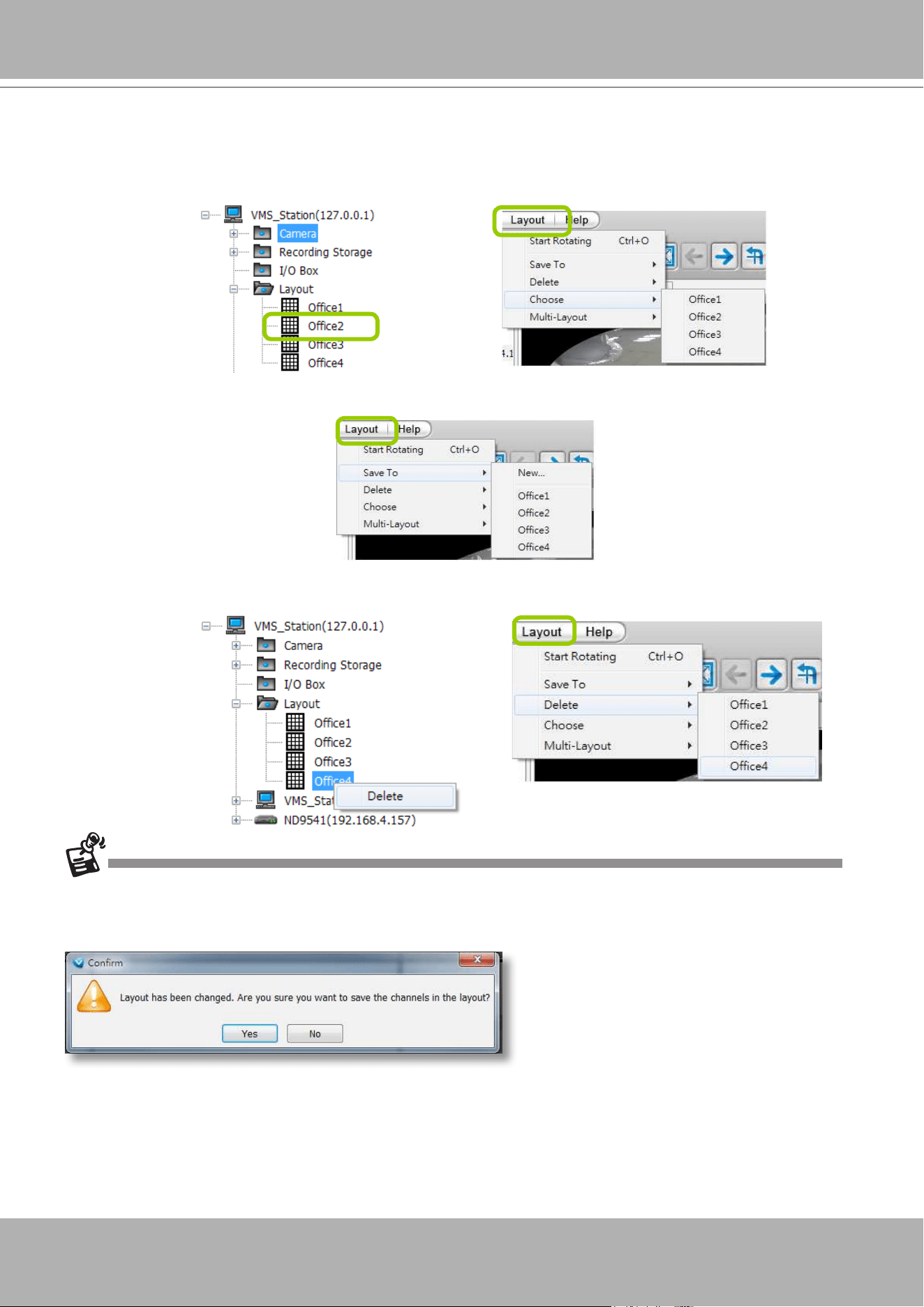
VIVOTEK - A Leading Provider of Multimedia Communication Solutions
User's Manual - 135
d. Back to the monitoring window, the new layout will be displayed under the hierarchical management
tree as shown below. You can save up to 10 layouts.
e. To change to another layout,
double-click
the layout options on the hierarchical management tree, or
click
Layout > Choose
on the menu bar
to select a desired layout.
If you want to edit an existing layout, arrange a layout mode and drag devices to the desired video
cells, then click
Layout > Edit > Save to > New
to save as a new layout
or an
existing layout
to
replace with the new one.
If you want to delete an existing layout,
right-click
the layout item on the hierarchical management
tree or click
Layout > Edit > Delete
on the menu bar to delete it.
Whenever you close the LiveClient or Playback programs and changes in screen layout have been
made, you will be prompted to save your current conguration.
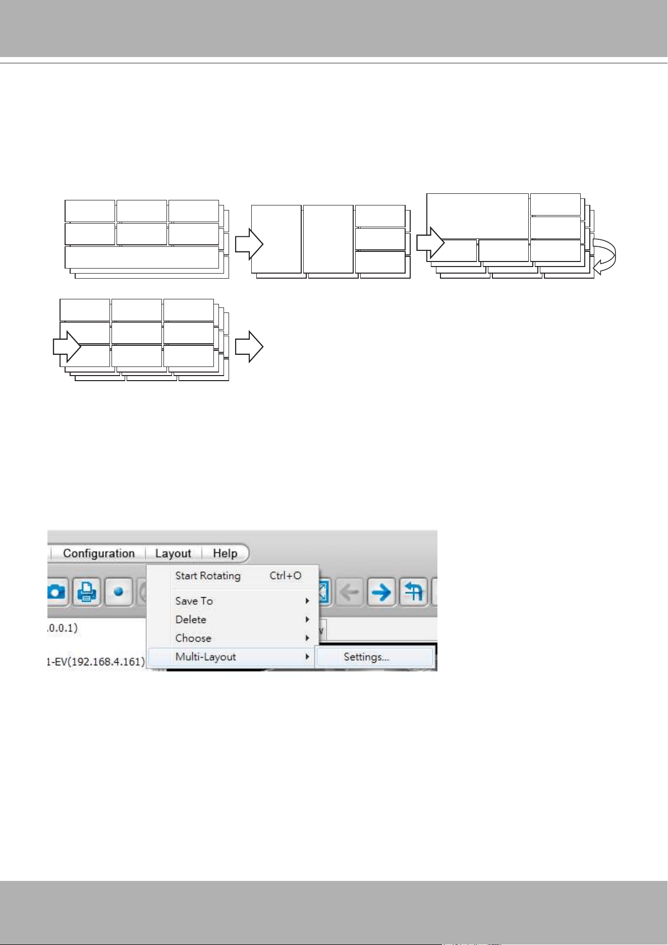
VIVOTEK - A Leading Provider of Multimedia Communication Solutions
136 - User's Manual
Scheduled Layout Rotation
In a conguration consisting of a large number of cameras, you can congure different layouts containing
view cells of different characteristics, e.g., a V view for a vertical, corridor scene, or a P view for
panoramic glimpse of the scene. With these layouts, you can congure an automated layout rotation.
Each layout will be displayed in turn, for a congurable dwell time.
10 sec 6 sec 6 sec
8 sec
3 pages 2 pages
4 pages
4 pages
....
A time frame can be congured for each layout rotation. For example, one rotation may take place during
the ofce hours, while another will take place during the off-ofce hours. Conguring a time frame for the
layout rotation is optional. If not preferred, you can select the "Always" time frame template.
To congure a Scheduled Layout Rotation,
1. The precondition is that you should have multiple layouts created for your application needs.
2. Click on
Layout
>
Multi-layout
>
Settings
.
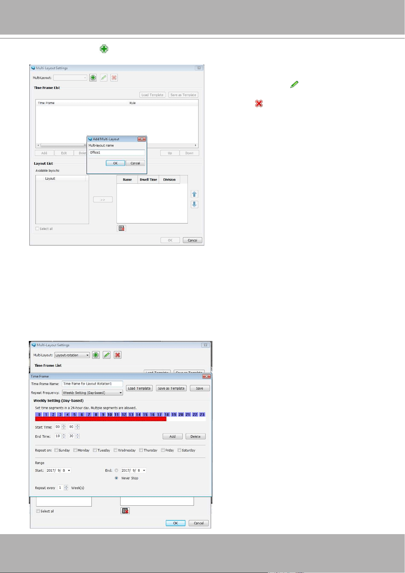
VIVOTEK - A Leading Provider of Multimedia Communication Solutions
User's Manual - 137
3. Click on the
Add
button to create a new scheduled layout rotation. Enter a name for the layout
rotation. Avoid using these non-alphanumeric characters: (<>&'"). -.
4. Click on the
Add
button on the Time Frame pane to create a time frame. You can manually enter the
Start and End time, or drag the time frame for the span of time you prefer. When done, click on the
Add
button to create the time frame.
You can use the
Load Template
button to select a pre-congured template, such as the Ofcehour,
OffOfcehourinWorkday, Weekend, or Workday template. Make adjustments to the span of time. You
can save your current time frame as a tempate for later use.
If necessary, select the days within a week, or the effective range for the time frame.
Click on the
Edit
button to change the
name of the configuration. Click on the
Delete
button to remove an existing
conguration.
The max. number of multi-layout
configurations is 128. Up to 256 individual
layouts can pair with a time frame.
Note that you can not edit a multi-layout
conguration while it is performing a rotation.
Click
Save
to complete the time frame
conguration.
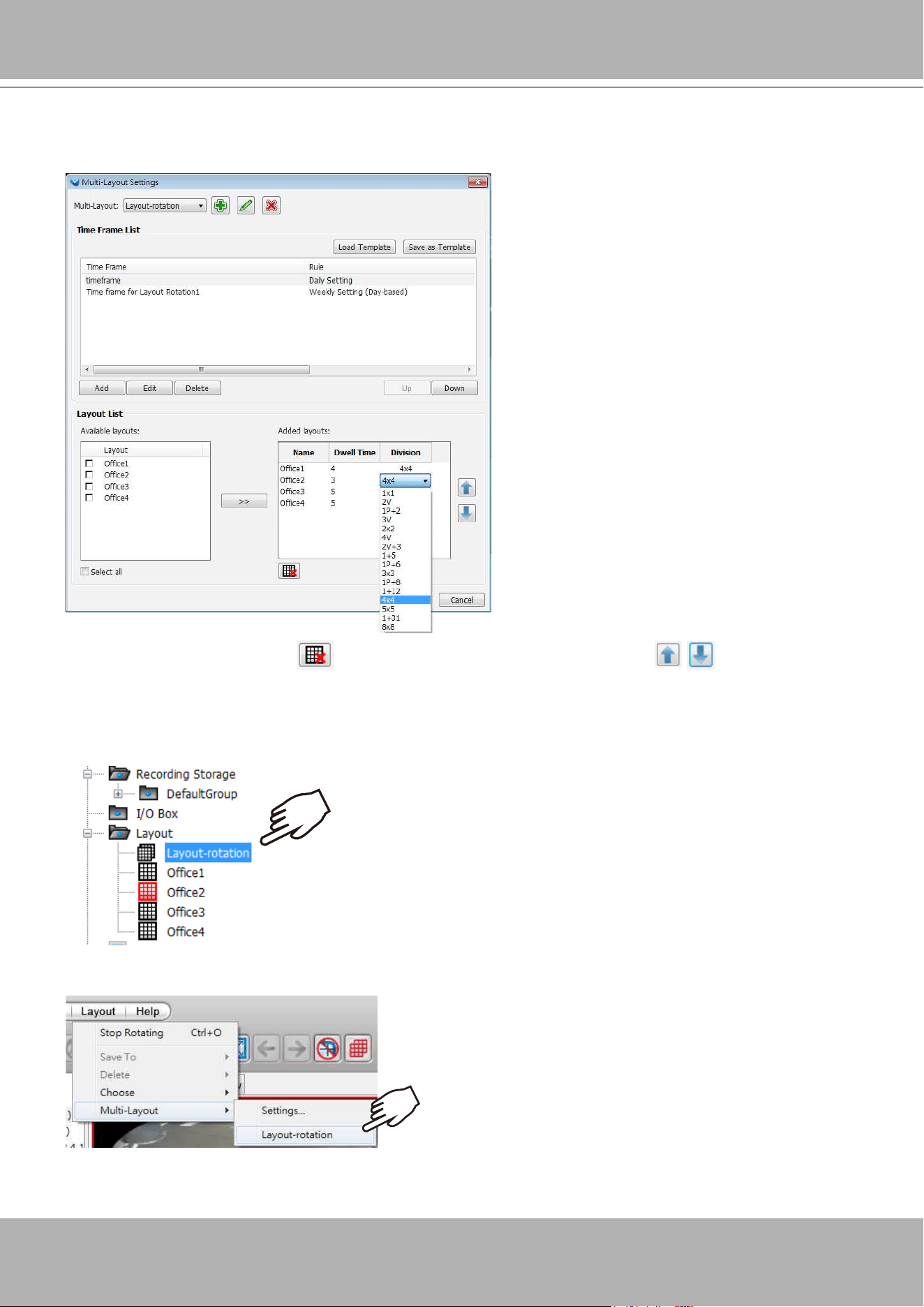
VIVOTEK - A Leading Provider of Multimedia Communication Solutions
138 - User's Manual
5. Select the layouts that will be included in the Layout Rotation.
When done, click on the
Dwell Time
and
Division
eld to edit their appearance and behavior on the
live view.
If necessary, use the Delte button to remove a layout. Use the move buttons to change
the display sequence of congured layouts.
6. You can start a Scheduled Rotation in many ways. Once congured, a Layout Rotation icon will appear
on the device list. You can double-click on it to start the rotation.
X2
You can start a Rotation from Layout > Multi-Layout > Layout-rotation.
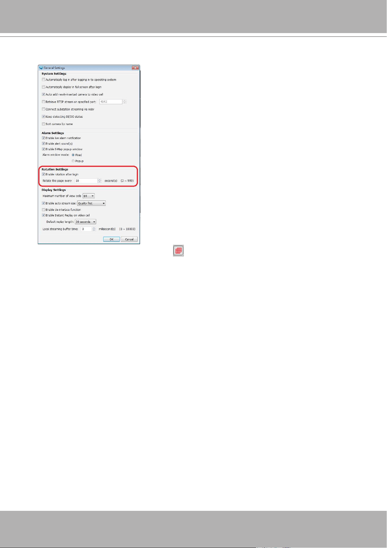
VIVOTEK - A Leading Provider of Multimedia Communication Solutions
User's Manual - 139
A rotation automatically starts with pre-congured layouts if you congure the option in
Conguration
>
Client Settings
>
General Settings
.
To stop a rotation, click on the Stop button
on the tool bar. This button turns red when a rotation is
taking place.
You can also double-click on an existing layout to stop the rotation.
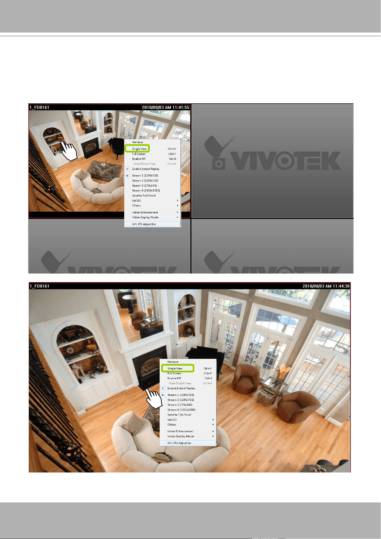
VIVOTEK - A Leading Provider of Multimedia Communication Solutions
140 - User's Manual
Maximize/Minimize the Live Video Monitoring Window
Single View: to maxmize a video cell to the entire live video window
Double-click
the video cell, or
right-click
the video cell and select
Single View
. The focused video will
occupy the entire playback window as shown below.
To restore to the original layout,
double-click
the video cell or
right-click
the video cell and uncheck
Single View.
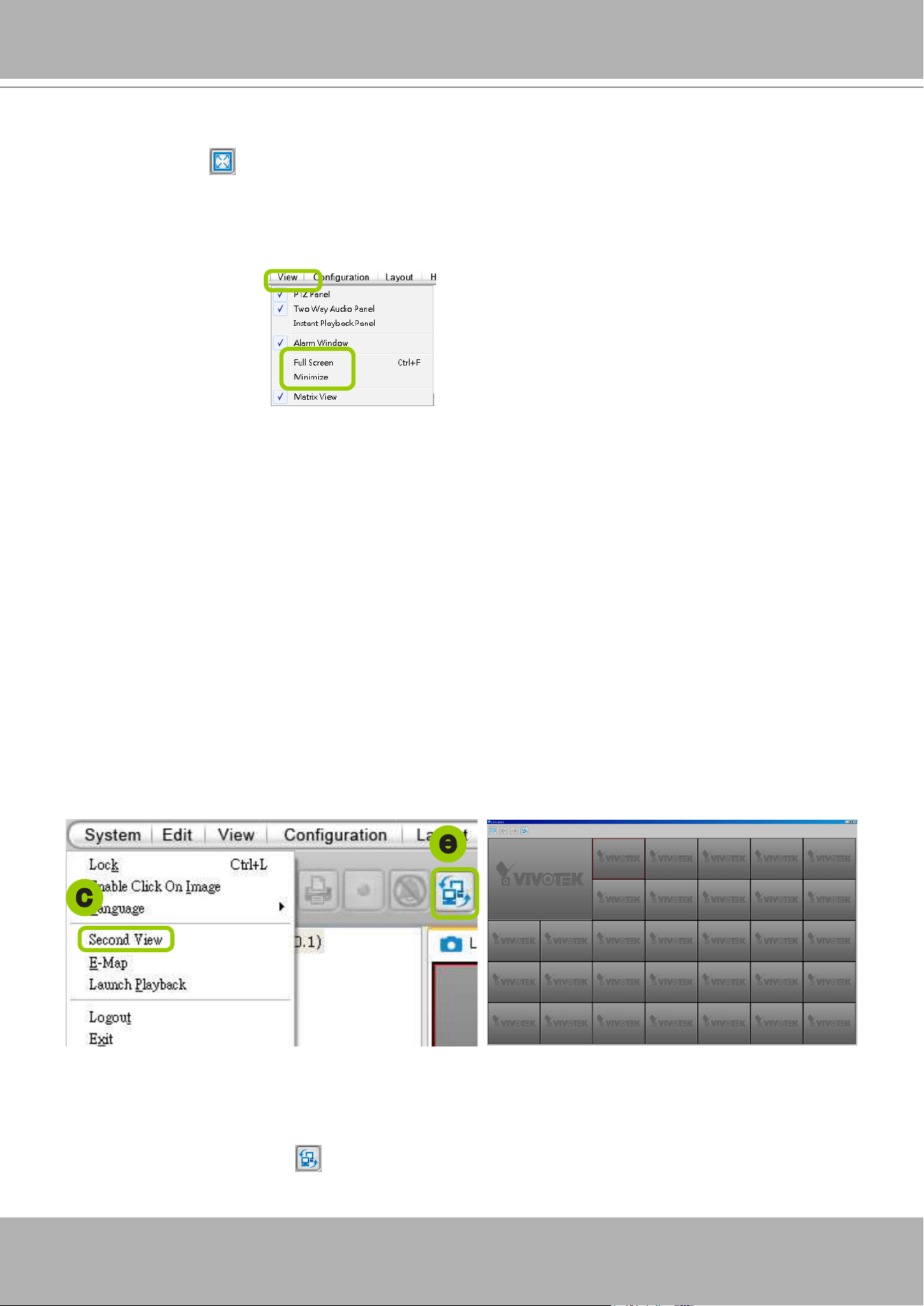
VIVOTEK - A Leading Provider of Multimedia Communication Solutions
User's Manual - 141
Full Screen: Maximize the live video monitoring window to the entire screen
Click
Full Screen
on the quick access bar or
right-click
the video cell and select
Full Screen
. In
addition, you can also click
View > Full Screen
on the menu bar to maximize the live video monitoring
window.
To restore to the original layout, you can
right-click
a video cell and uncheck
Full Screen
or click the
Esc
button on the keyboard to exit full screen mode.
Minimize: If you click
View > Minimize
on the menu bar, LiveClient will minimize to the Windows tool
bar.
View Live Video on Dual Monitors
VAST also supports live video viewing on dual monitors, allowing you to manage a maximum of
64 channels concurrently on two screens. Moreover, the layout of the video monitoring window
on different monitors can be set up individually.
Please follow the steps below to set up dual-screen mode:
a. Set up dual monitors for your local computer.
b. Launch VAST LiveClient on monitor 1.
c. Click
System > Second View
on monitor 1, then the live video monitoring window will be displayed in
monitor 2 as shown below.
d. There are two ways to view live videos. One is to
drag-and-drop
the target device from the
hierarchical management tree window to the video cells. The other is to click any video cell on monitor
1 or monitor 2, then
double-click
the target device; the live video will be displayed in monitor 1 or 2 in
accordance with your selection.
e. If you click
Switch Screen
on the quick access bar, the live monitoring window on monitor 1 and
monitor 2 will swap.
Monitor 1
Monitor 2
c
e
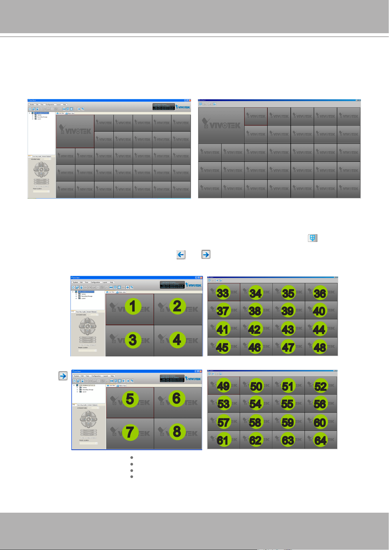
VIVOTEK - A Leading Provider of Multimedia Communication Solutions
142 - User's Manual
Simultaneously Viewing up to 128 Channels
If you select 1+31 layout on dual screens, you can view a maximum of 128 channels live video
simultaneously. In this case, each layout contains 32 channels on 1 video page.
Using different layouts on each monitor
You can also select different layout for two monitors, simply click the
Layout
button on the quick
access bar. Below is an example of the 2x2 layout with 8 video pages on monitor 1 and the 4x4 layout
with 2 video pages on monitor 2. You can click
and to switch among the video pages.
Monitor 2 - page 1
Monitor 1 - page 1
Monitor 1 - page 2
Click
1
2
3
4
5
6
7
8
34 35
36
37 38 39
40
41 42 43
44
45 46 47
48
33
Monitor 1 - page 8
50 51
52
53 54 55
56
57 58 59
60
61 62 63
64
49
Monitor 1 - 32 channel
Monitor 2 - 32 channel
Monitor 2 - page 2
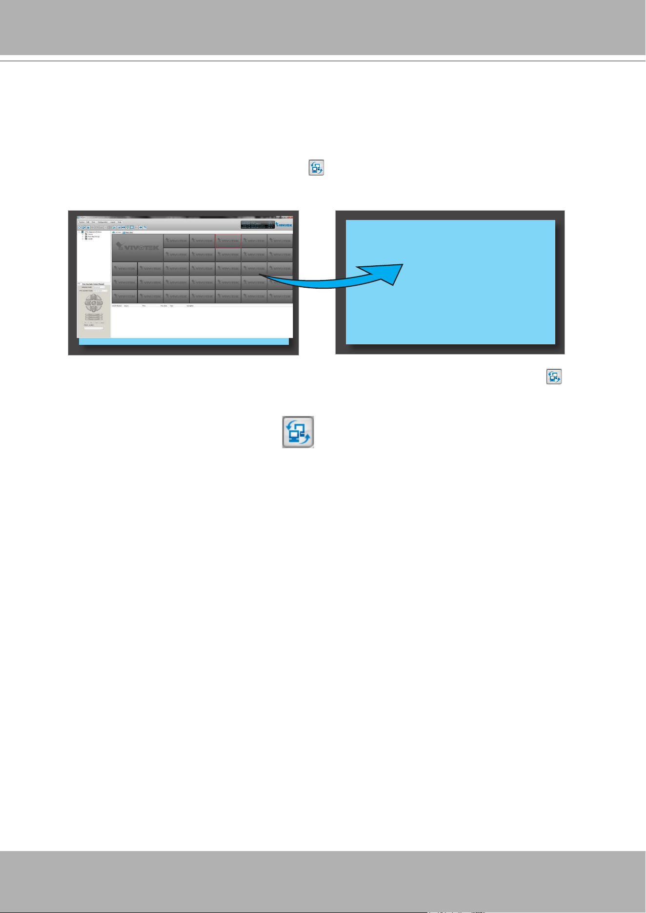
VIVOTEK - A Leading Provider of Multimedia Communication Solutions
User's Manual - 143
View Live Video with Multiple Monitors
If you have multiple screens in your monitoring center, you can switch the VAST LiveClient
Window among these screens.
If you have two monitors, click
Switch Screen
on the menu bar; the LiveClient window on monitor
1 will switch to monitor 2.
If you have two monitors, a drop-down list will be displayed when you click
Switch Screen
on the
menu bar. The number of items on this list depends on the number of your screens. Select a desired
screen on the drop-down list and the LiveClient Window will switch to the specied screen.
Monitor 1 Monitor 2
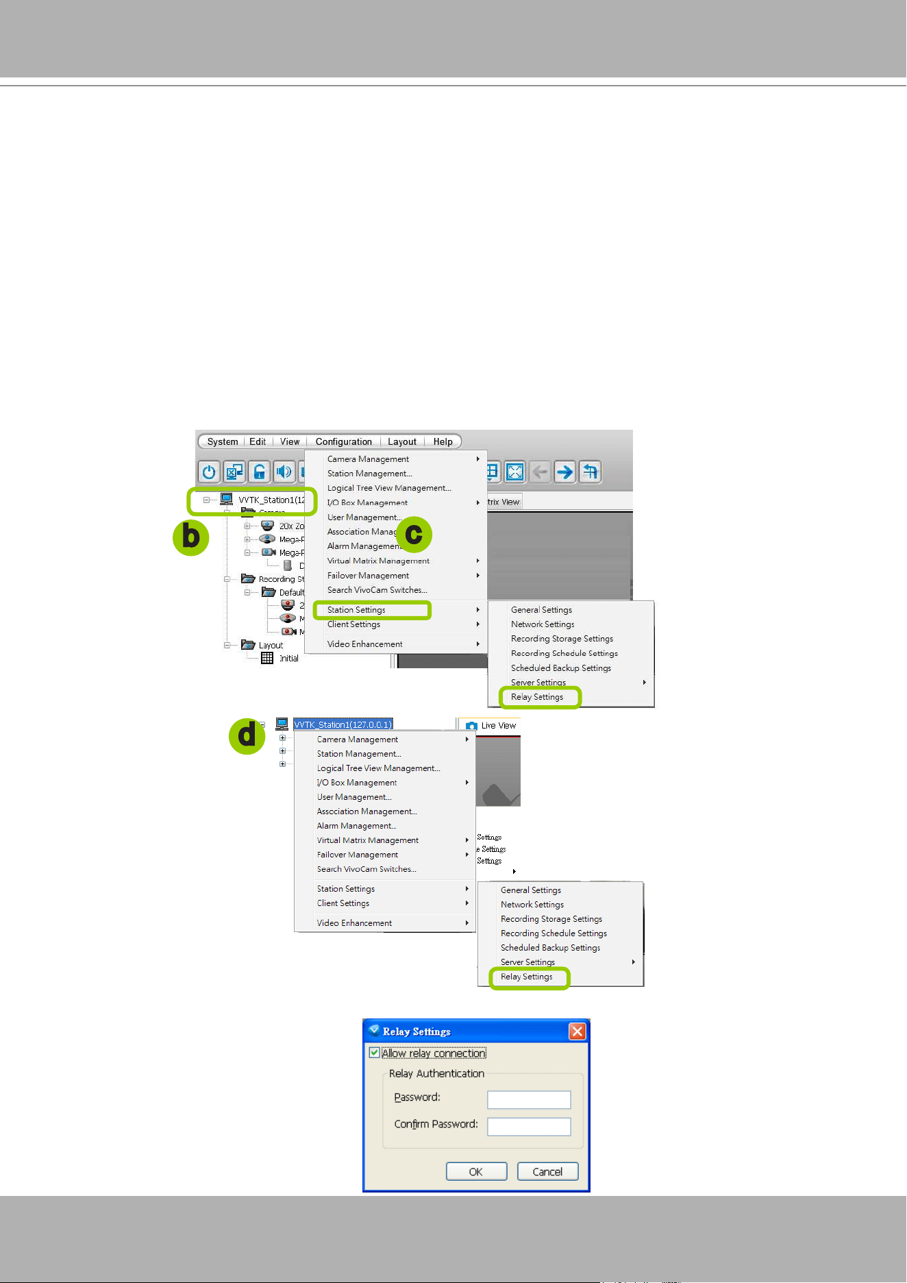
VIVOTEK - A Leading Provider of Multimedia Communication Solutions
144 - User's Manual
How to Manage Stations
The VAST Server allows you to construct a hierarchical management system by adding more
sub-stations to the root station. Under each sub-station, it can also insert sub-stations and
network cameras.
Relay Settings
Before adding a sub-station, please follow the instruction below to enable the sub-station's
Relay Settings rst.
a. Login to the sub-station.
b. Select the station from the hierarchical management tree.
c. Click
Conguration > Station Settings > Relay Settings
on the menu bar (or
right-click
the station
on the hierarchical management tree and select
Station Settings > Relay Settings
).
d. The
Relay Settings
window will pop up. Check
Allow Relay Connection
and enter a
Password
.
Then click
OK
to enable the settings.
b
c
d
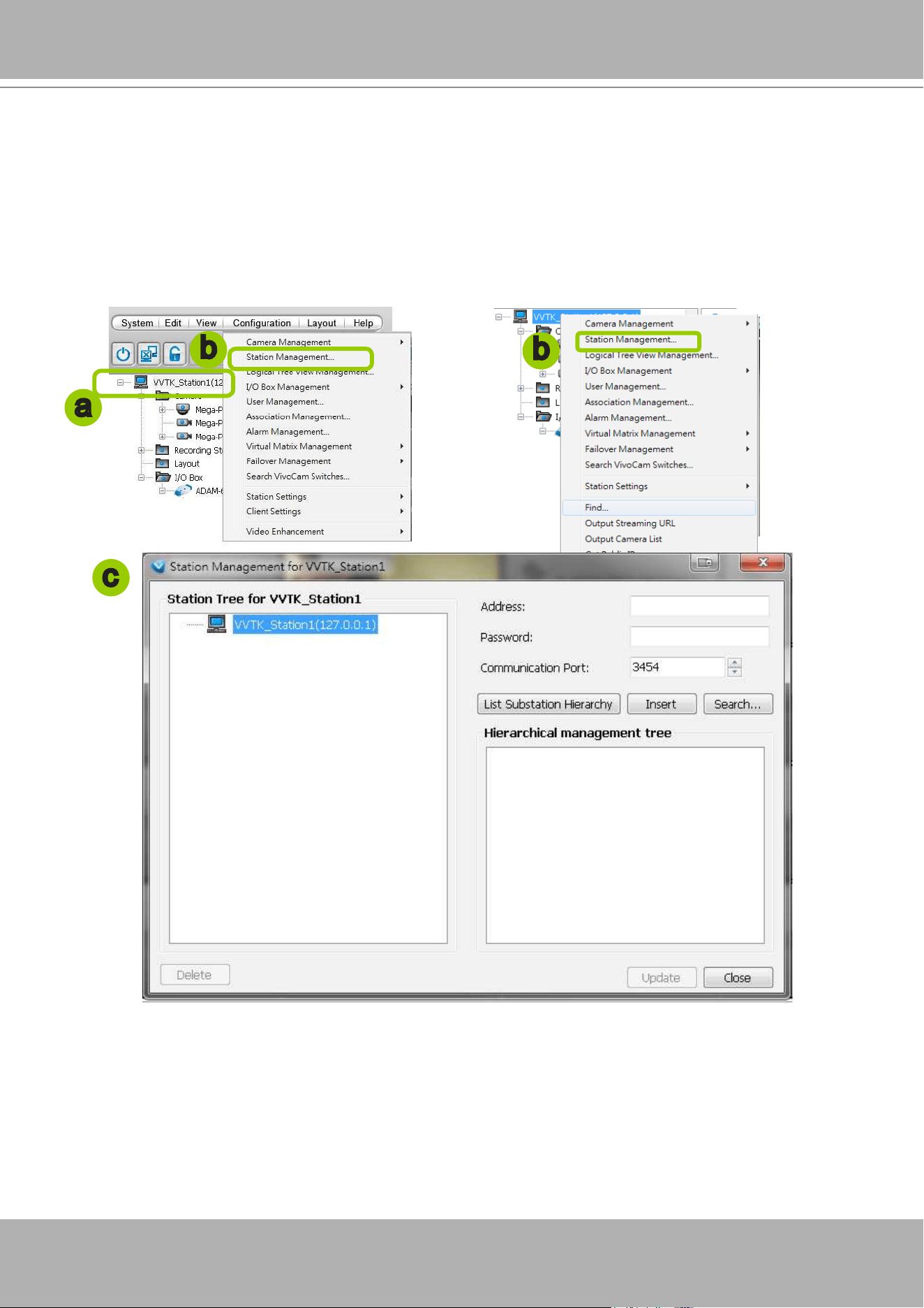
VIVOTEK - A Leading Provider of Multimedia Communication Solutions
User's Manual - 145
Insert Sub-stations
Please follow the steps below to add sub-stations:
a. Select a target station from the hierarchical management tree.
b. Click
Conguration > Station Management
on the menu bar (or
right-click
the target station, then
select
Station Management
).
c. The
Station Management
window will pop up. The hierarchical management tree managed by the
target station will be displayed on the left panel.
d. Before inserting the sub-station, you can click
List Sub-station Hierarchy
button to know if there is
any sub-station under it.
e. Enter the sub-station's
IP address
and
Password (dened in Relay Settings, not login password)
.
The default communication port is 3454.
If the sub-station is on the LAN, you can click the
Search Station
button to detect all ST7501 and
VAST on the LAN. A
Station List
window will pop up and show a list of detected cameras on
the LAN. On the top of
Camera List
window, you can select "
List the stations which are not
inserted
" or "
List all stations
". The items listed below will then change accordingly. You can click
Name, IP Address, Model, Http port
to sort the items. Then select a device from the list to insert
to the station.
b
a
b
c
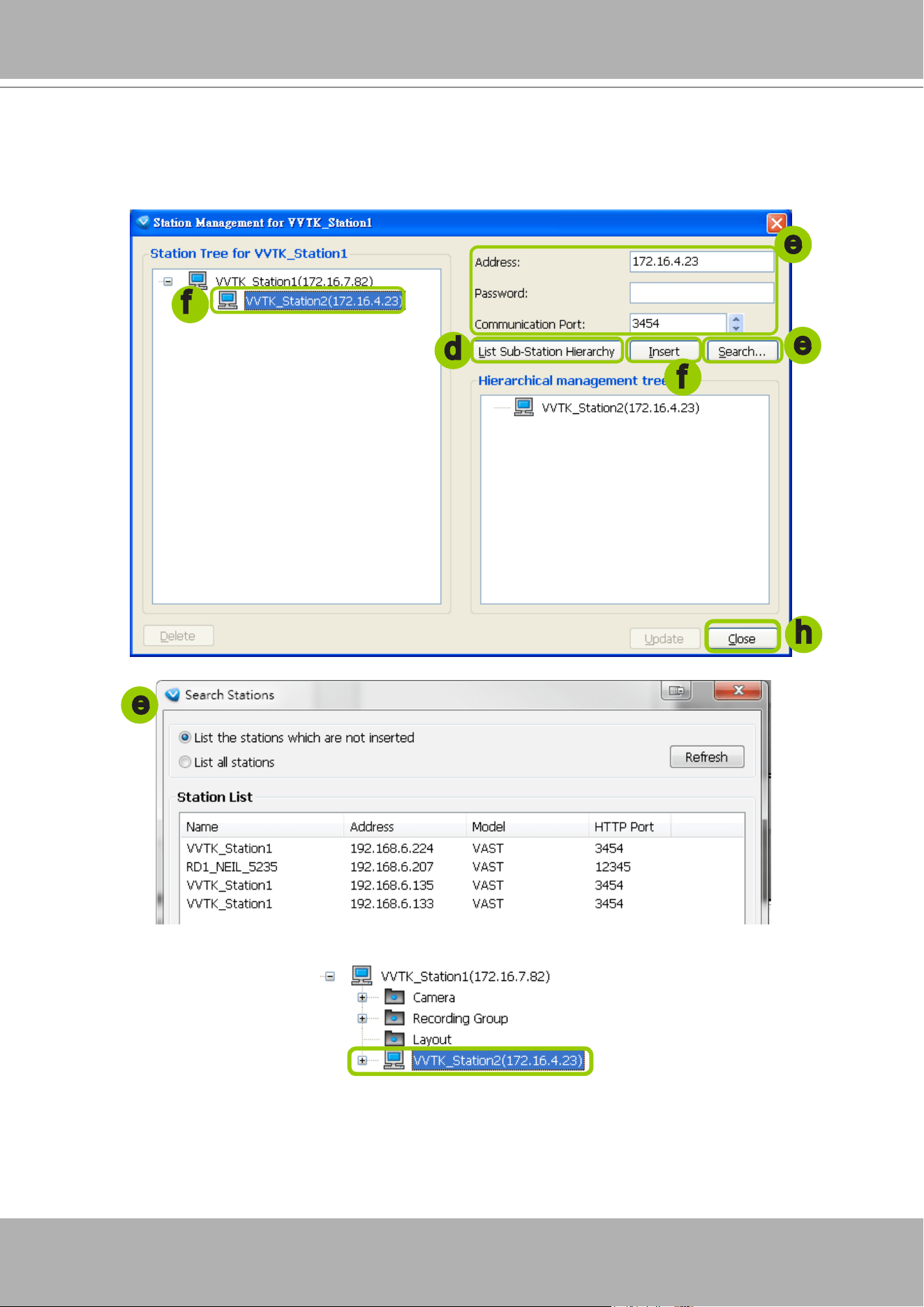
VIVOTEK - A Leading Provider of Multimedia Communication Solutions
146 - User's Manual
f. When all settings are done, click
Insert
to add the sub-station to the target station. The sub-station will
be displayed under the left station tree.
g. To insert additional sub-stations to the target station, repeat the above steps.
h. When completed, click
Close
to exit the Station Management window.
i. Back to the main window, you will find the newly-inserted stations displayed under the hierarchical
management tree.
e
d
f
f
h
e
e
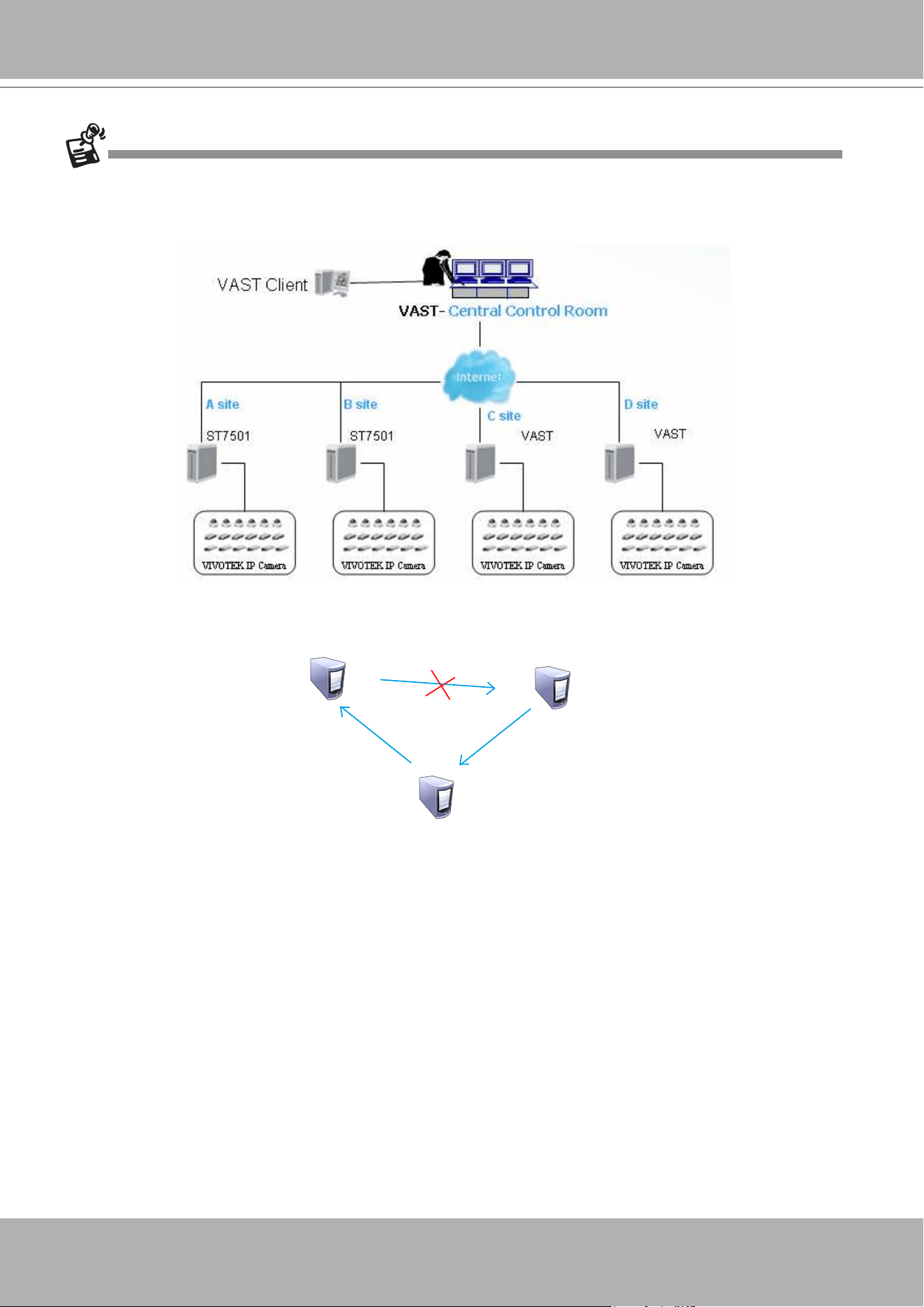
VIVOTEK - A Leading Provider of Multimedia Communication Solutions
User's Manual - 147
You can add VAST or free standard ST7501 as the sub-stations. The number of sub-stations can be
added to the server depends on your key dongle. The VAST server will automatically detect the USB
dongle installed on your host PC. Following is an illustration for two-level hierarchical architecture:
Please note that the following cyclic relay is not allowed.
Server A
Server C
Server B
Add server B
as substation
Add server C
as substation
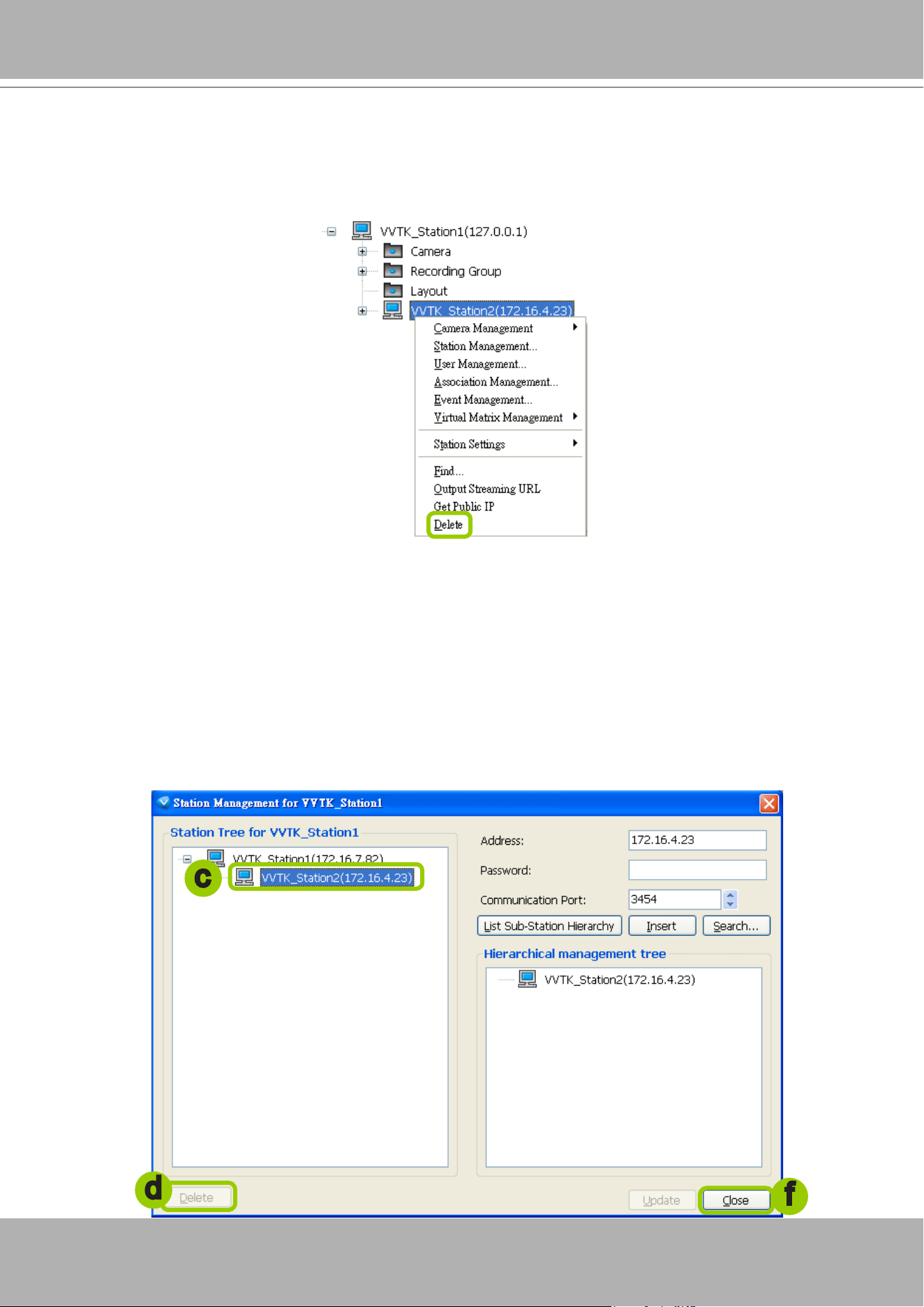
VIVOTEK - A Leading Provider of Multimedia Communication Solutions
148 - User's Manual
Delete Sub-stations
There are two ways to delete a sub-station:
Method 1. Select the sub-station on the hierarchical management tree, then
right-click
to delete.
Method 2. Delete the sub-station via the Station Management window:
a. Click the station on the hierarchical management tree, then click
Configuration > Station Manage-
ment
on the menu bar (or
right-click
the station, then select
Station Management
).
b. The
Station Management
window will pop up. The hierarchical management tree managed by the
station will be displayed in the left Station List window.
c. Select a station from the list you want to delete. Its related information will automatically be displayed
in the corresponding blanks in the Station Management window.
d. Click
Delete
to delete it.
e. To delete additional devices, repeat step c. and d.
f. When completed, click
Close
to exit the camera management window and return to the main window.
The deleted device will disappear from the hierarchical management tree.
d
c
f
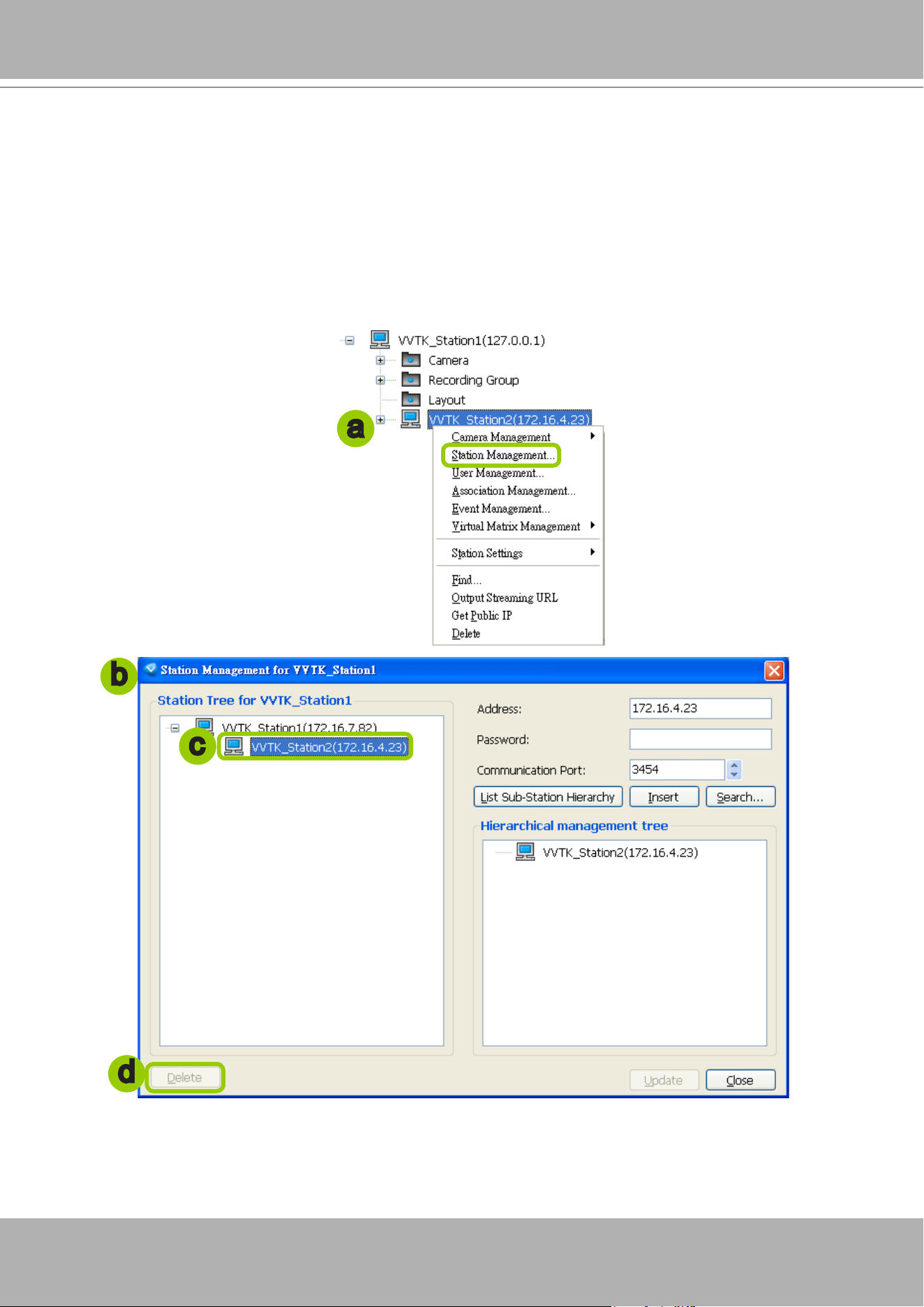
VIVOTEK - A Leading Provider of Multimedia Communication Solutions
User's Manual - 149
Update Stations
Please follow the steps below to update a station via Station Management window:
a.
Right-click
the target device on the hierarchical management tree and click
Station Management.
b. The
Station Management
window will pop up. The hierarchical management tree managed by the
station will be displayed in the Station List window on the left.
c. Select a station from the list you want to delete. Its related information will automatically be displayed
in the corresponding blanks in the Station Management window.
d. When all settings are completed, click
Update
to enable the settings.
a
d
c
b
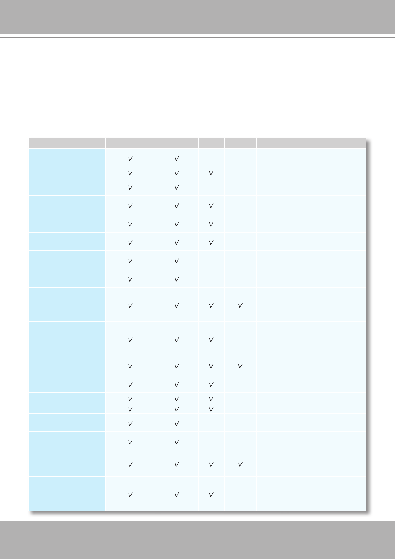
VIVOTEK - A Leading Provider of Multimedia Communication Solutions
150 - User's Manual
How to Manage User Accounts
VAST allows users to apply multiple user accounts to a station with five levels of user roles:
Administrator > Power User > User > Operator > Guest. Each role has different permissions
listed as shown below. Moreover, Administrators have the highest privileges, while Power Users
can only add/edit users as Power Users, Users, Operators, and Guests.
The Default User Roles and Permissions of User Accounts
Functions \ User Roles Administrator Power User User Operator Guest Description
Station Management
Add sub-station under the
existing station
User Management
Manage user accounts
Camera Management
Insert and congure the
camera settings
Association
Management
Access and modify the
association settings
Access Alarm
Management
Access Alarm management
Modify Alarm
Management
Modify Alarm management
General Station
Settings
Modify general station
settings
Station Network
Settings
Modify network settings
Access Recording
Storage/
Recording Schedule
Settings
Access the recording group
and recording schedule
Modify Recording
Storage/
Recording Schedule
Settings
Congure the recording
group and recording
schedule
Manually Record
Enable the recording
function manually
Scheduled Backup
Settings
Congure backup schedule
Access Server Settings
Access server settings
Modify Server Settings
Modify server settings
License Management
Allow user to manage
station licenses
Relay Management
Allow user to manage
station relaying settings
Client Settings
Congure the client
settings: snapshot, AVI,
etc.
Video Enhancement
Settings
Allow user to edit prole for
video enhancement and
assign prole to camera in
LiveClient
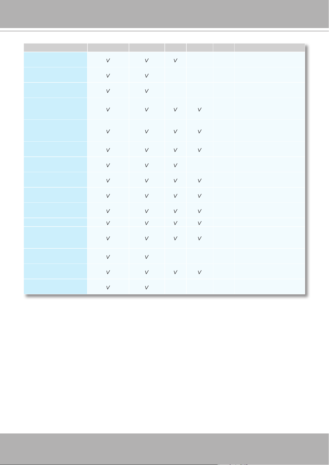
VIVOTEK - A Leading Provider of Multimedia Communication Solutions
User's Manual - 151
Privileges \ User Roles Administrator Power User User Operator Guest Description
Modify Directories
Add, remove and rename
directories
Delete Station
Delete sub-station from a
(parent) station
Delete Camera
Delete camera from the
station
PTZ Control
PTZ control for PTZ
cameras and speed domes
in LiveClient
Device Control
Control the digital output or
white light/IR illuminators of
the cameras
Talk Control
Two way audio function for
the cameras
Access Camera
Conguration
Access the camera settings
Modify E-map
Allow user to modify the
E-map
Event Search
Use built-in search engine
to search specic events
Log Viewer
Use built-in search engine
to search the log
Backup
Back up database manually
Record/Export Media
Record live stream or
export playback stream to
local les
Virtual Matrix
Management
Allow user to manage
virtual matrix
Virtual Matrix Control
Allow user to control virtual
matrix
Playback Authority
Allow user to access
Playback
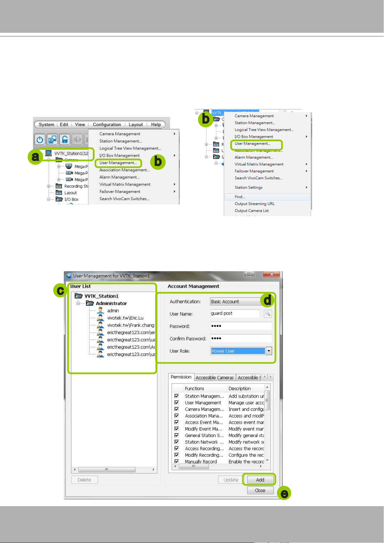
VIVOTEK - A Leading Provider of Multimedia Communication Solutions
152 - User's Manual
Manage a User Account
Add a New User Account - Basic Account
a. Select the station from the hierarchical management tree.
b. Click
Configuration > User Management
on the menu bar (or
right-click
the station, then select
User Management
).
c. The
User Management
window will pop up. The user accounts under the station will be displayed
under the left User List tree. Up to 1,021 users can be created (not including the default Admin and two
internal communication accounts).
d. Enter the
User Name
,
Password,
and specify the
User Role
of this user.
e. Click
Add
to add the user account to the station. It will be displayed under the User List.
c
d
e
b
a
b
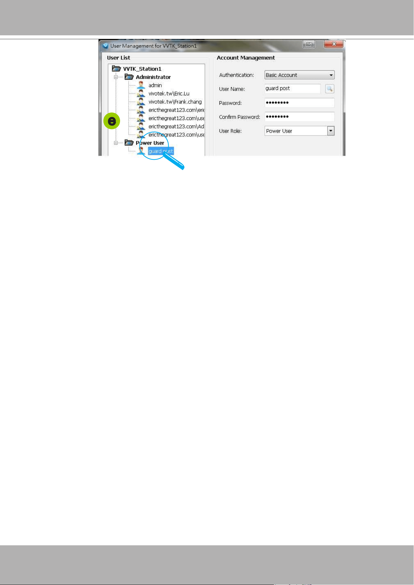
VIVOTEK - A Leading Provider of Multimedia Communication Solutions
User's Manual - 153
e
Add a New User Account - Windows AD Account
In an established, enterprise network environment, the support for Windows AD (Active Directory)
infrastructure enables ease of integration using the credentials of existing users. Using the same AD
authentication methodologies, you can congure the clients or users in an established network to access
the VAST server conguration.
Note the following with Windows AD support:
1. The ST7501 software does not support Windows AD accounts. However, if you log in to a VAST server
which supports Windows AD accounts, the AD account will work for an ST7501 sub-station managed
by VAST.
2. If you install VAST server on a Windows XP machine with Postqre SQL server, the login using a
Windows AD account will not work.
3. The VAST server must reside in a domain managed by the AD server.
4. This function does not support the environment that spans across multiple AD domains.
5. A user account hosted by an AD server cannot be modied in VAST.
6. A User Group and its members congured in AD cannot be managed in VAST.
7. You cannot add an account having the same name as one you used to log in VAST.
8. There are 3 types of account for VAST: VIVOTEK account, AD single user, AD group.
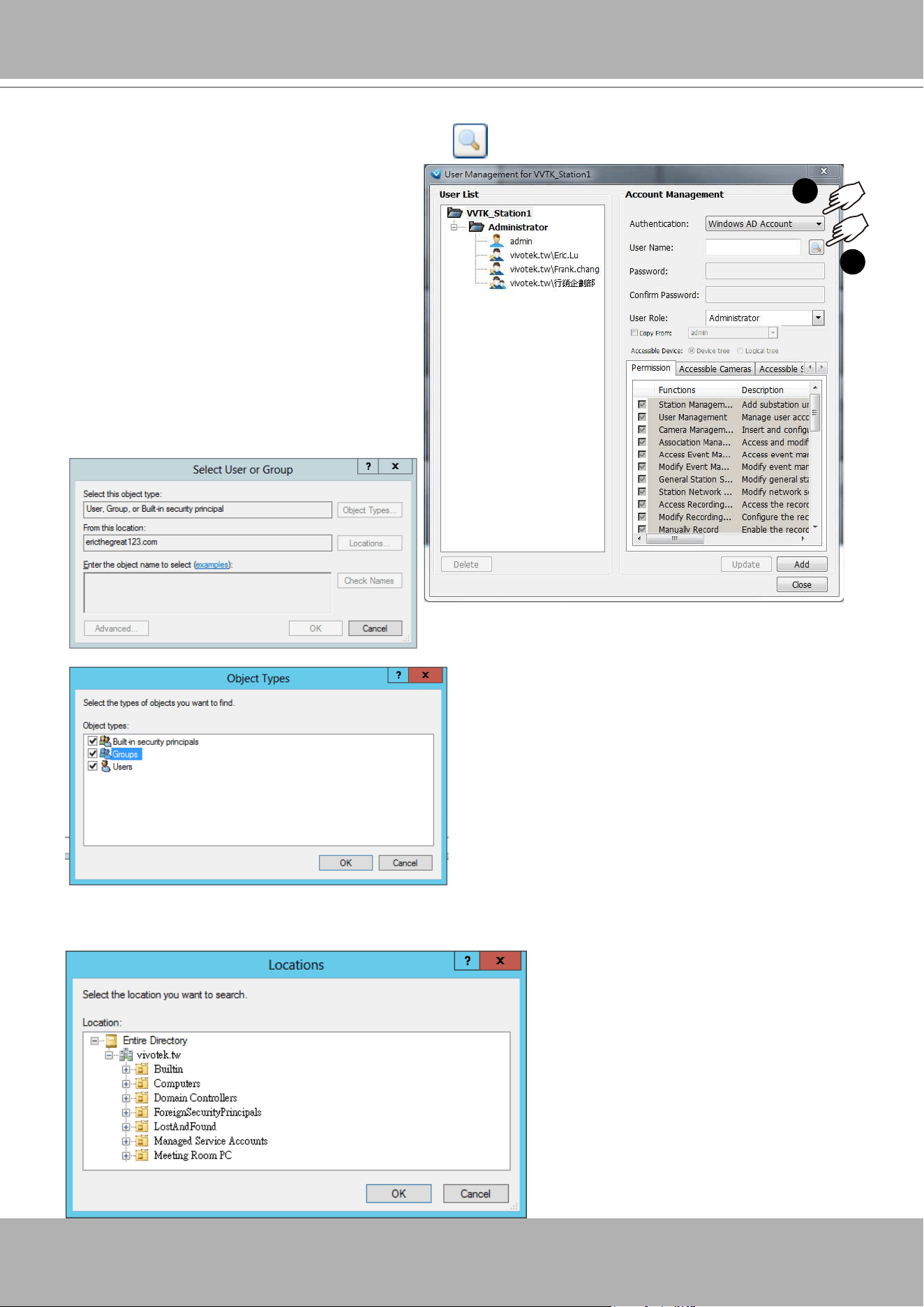
VIVOTEK - A Leading Provider of Multimedia Communication Solutions
154 - User's Manual
b. A Select User or Group window will prompt.
Click on the
Object type
button. Select
Group
or
User
.
c. You can also click on the
Location
button to specify a search range on a location on the AD
hierarchical tree, e.g., a department in an organization.
a. To configure a Windows AD user as a VAST user, enter the
User Management
window. Select
Windows AD Account
, and click on the
Search
button.
1
2
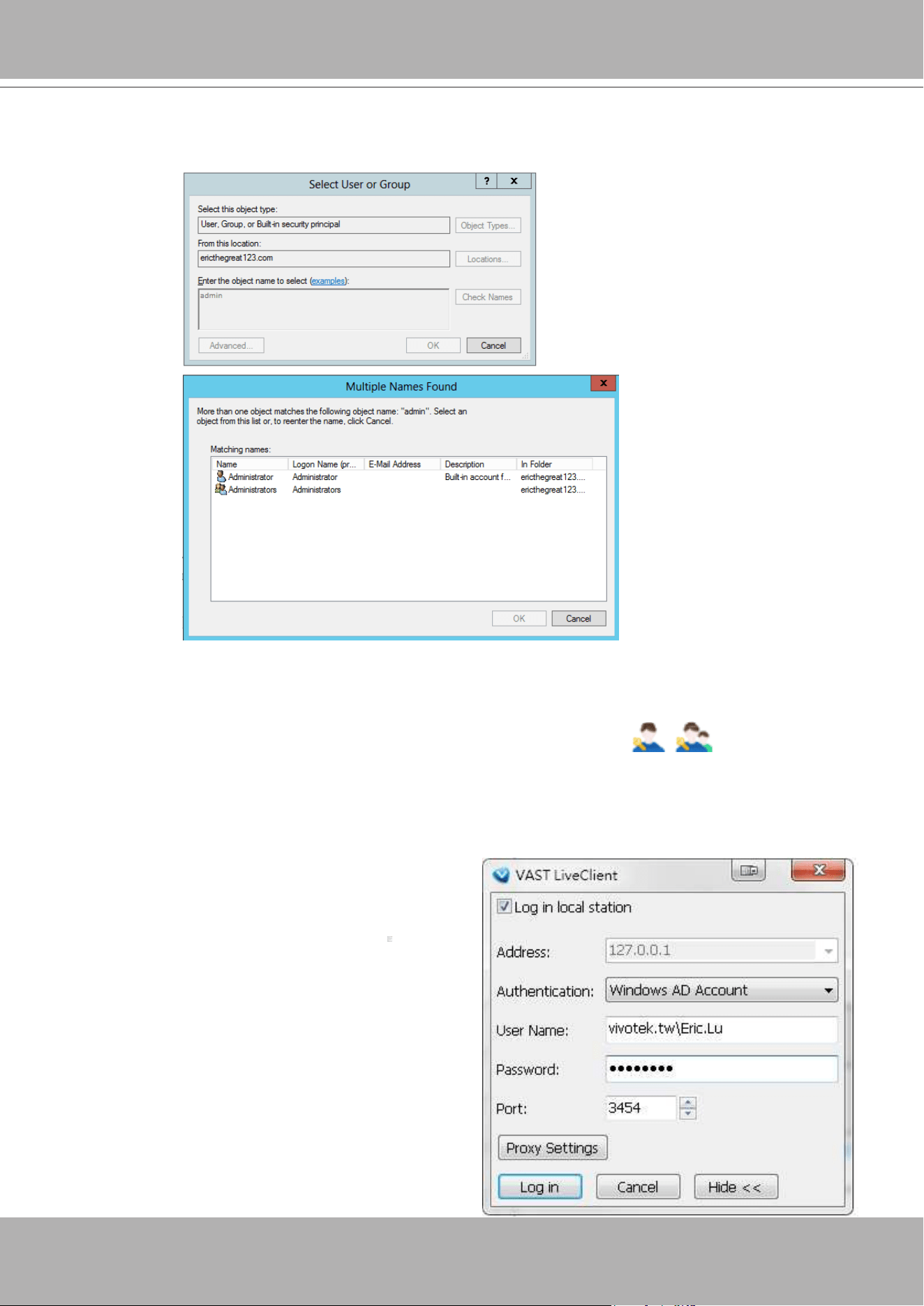
VIVOTEK - A Leading Provider of Multimedia Communication Solutions
User's Manual - 155
d. Enter a name for user or group that is known to the AD. Click on the
Check Name
button. The search
results will be listed.
e. Click to select a user, and then click
OK
to conrm your selection.
f. Users thus added will be listed on the left in the
User List
. These users or groups will be listed with
their domain name listed in front of them and indicated by different icons
.
g. Select a
User Role
for the AD user as Administrator, Power user, user, operator, or guest.
h. Select user's privileges in terms of the
Permission
,
Accessible Cameras
, and
Accessible
Substations
from the tabbed windows below.
i. Click the
Add
button to complete the process.
The next time you log in, you can select
Windows
AD Account
, enter User Name and Password to
access the VAST software.
Note that you should specify the domain name in
front of the user name; "domain name\user name."
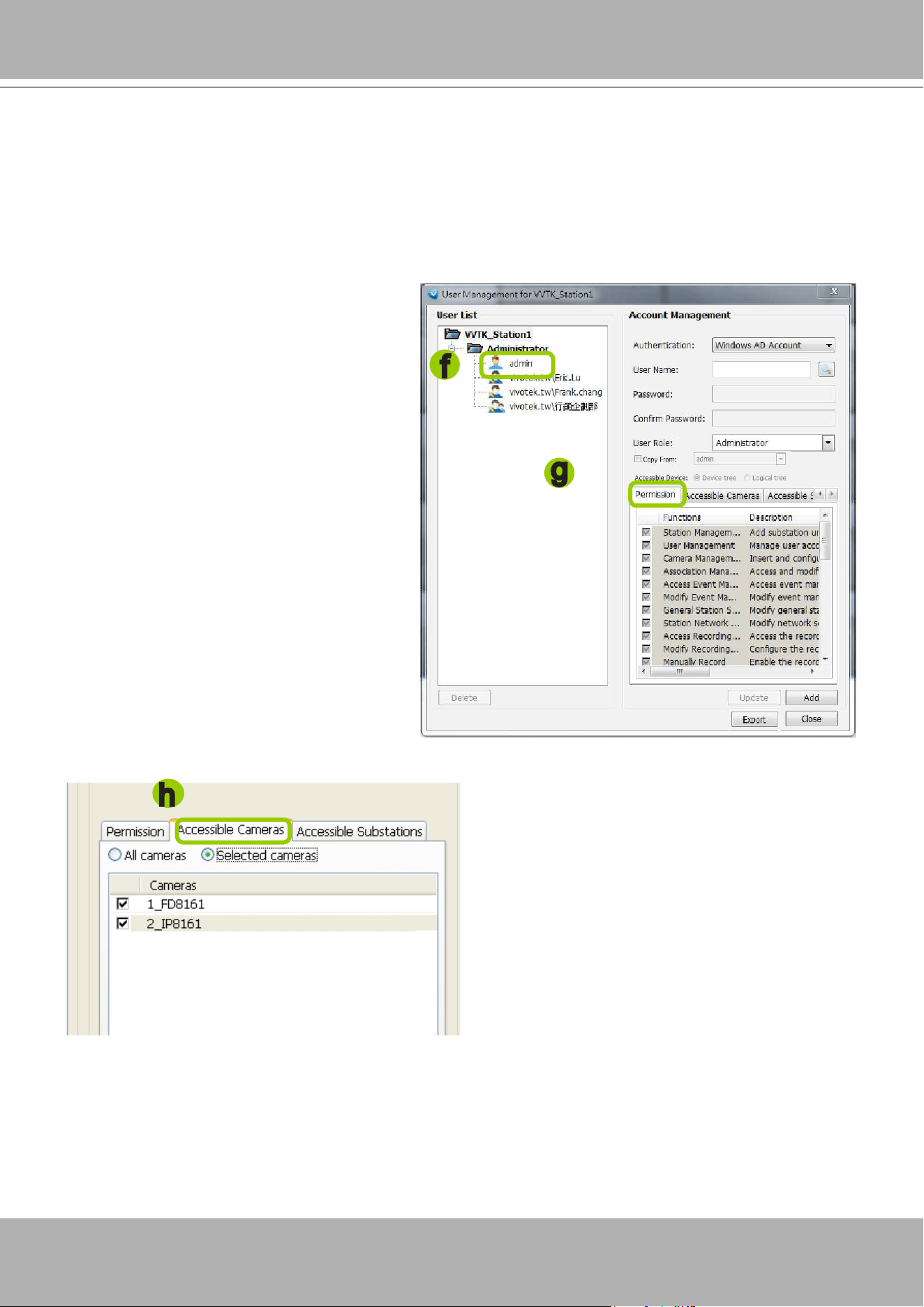
VIVOTEK - A Leading Provider of Multimedia Communication Solutions
156 - User's Manual
Permission of the User Account
Administrator is granted with all access privileges, while other user roles' permission is limited. If
you want to modify the permission, please login as the Administrator to congure the settings.
f. Select a User account from the User List tree.
g. If you want to set the limit of the permission
of the user, click
Permission
tab to check or
uncheck the items.
h. If you want to limit the devices accessible
by the user, click
Accessible Cameras
tab to
select the desired devices.
h
f
g
You can select either a basic user can access a device tree or a logical tree.
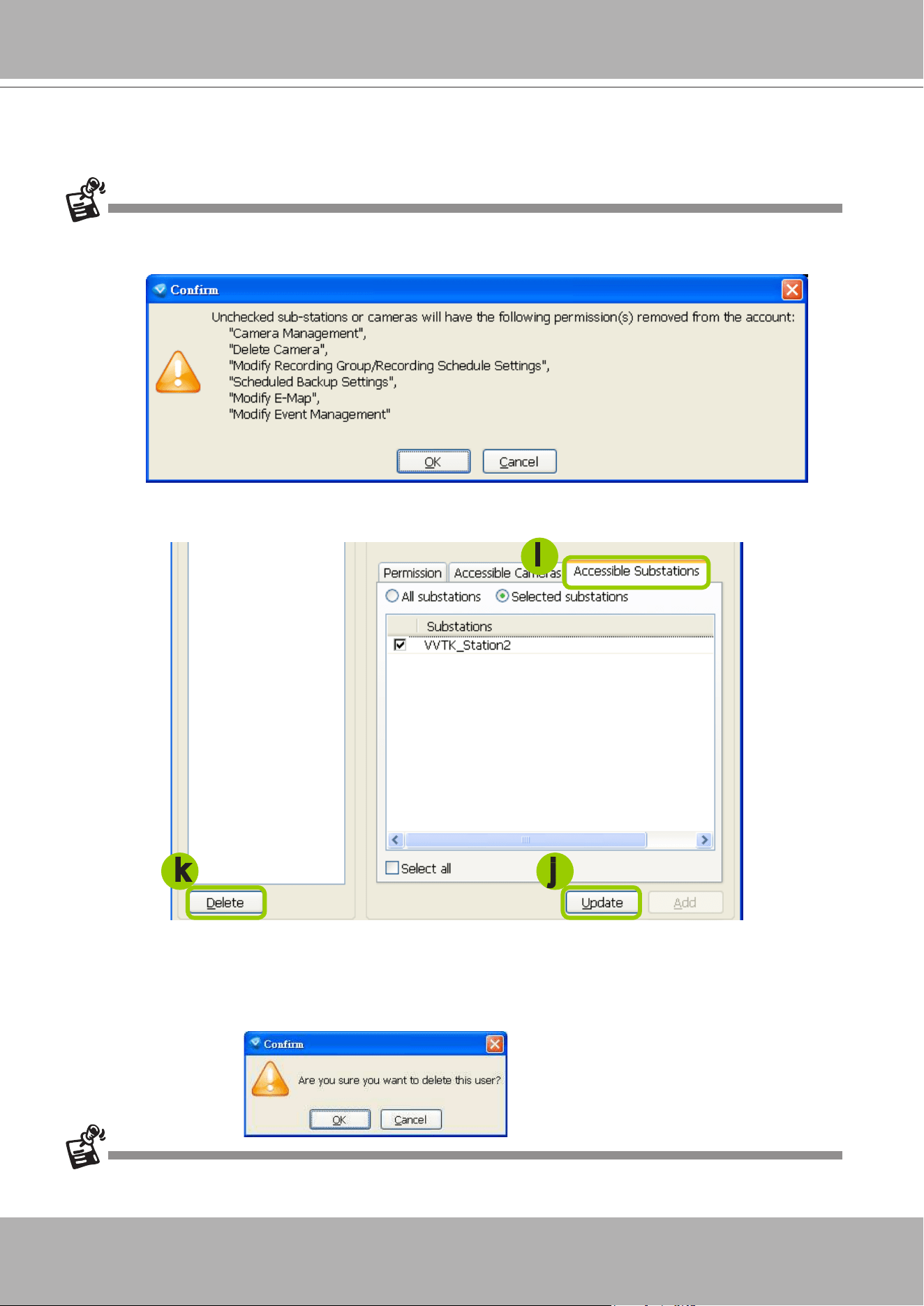
VIVOTEK - A Leading Provider of Multimedia Communication Solutions
User's Manual - 157
i. If you want to congure the access limit of the sub-station accessible by the user, click
Accessible
Substations
tab to select the desired devices.
If you want to remove access permission mentioned above from the account, the user will not able to
operate some functions listed in the following warning dialog.
j. When completed, click
Update
to enable the new settings.
Delete the User Account
k. Click
Delete
, a delete user dialog will pop up. Click
OK
to delete the user account.
If the Administrator modies or deletes the User Account, that modied user might be kicked off from the station.
i
jk
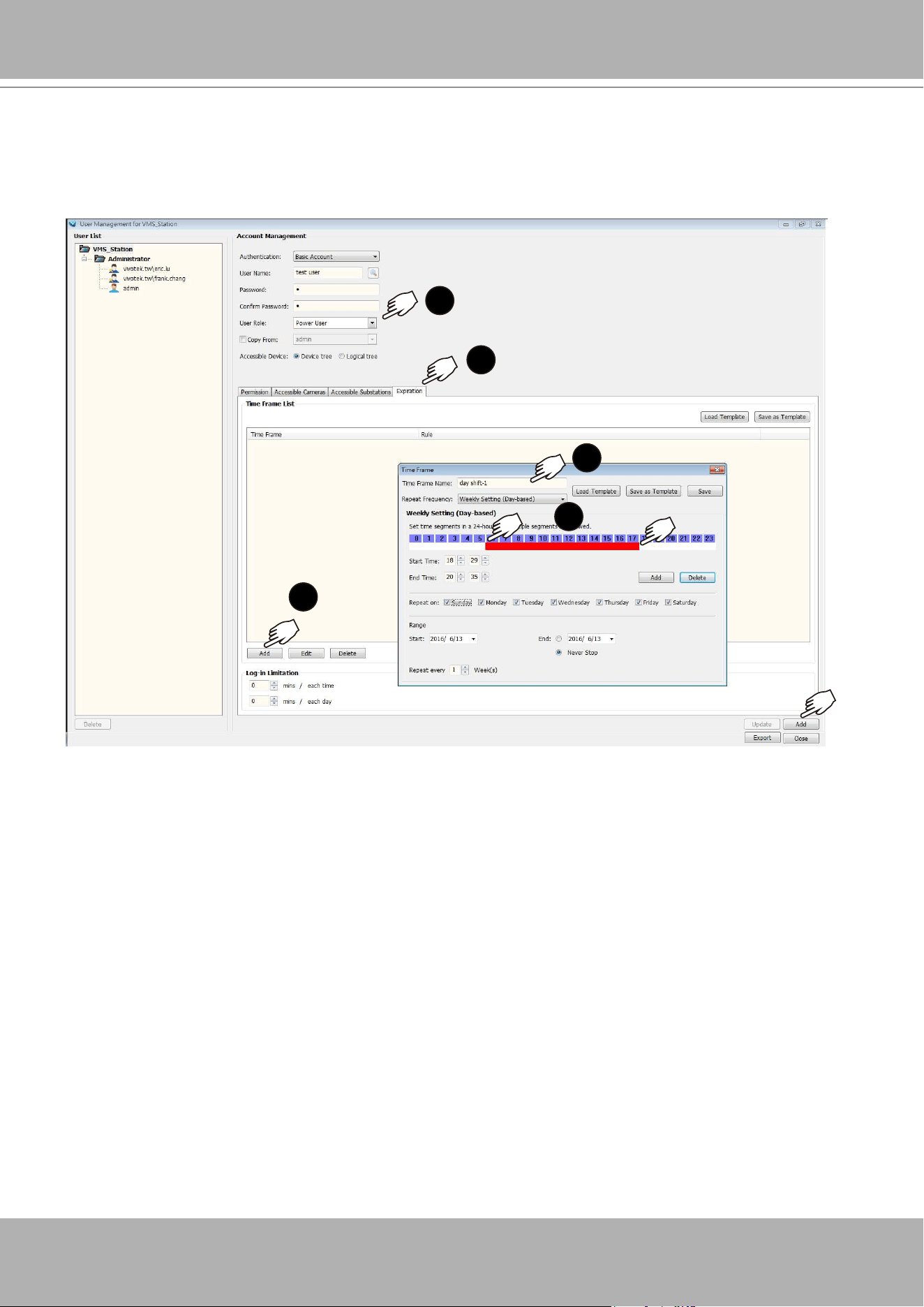
VIVOTEK - A Leading Provider of Multimedia Communication Solutions
158 - User's Manual
Expiration
Click
Expiration
to configure the extension of time allowed for a user's access. For example, an
administrator may want some users to have access to the LiveClient during a specic period of time,
while they are forbidden to access when they are not on the duty.
1
2
3
4
5
Note that if a new user has the
Administrator
previlege, no Expiration setting will apply to him.
The Expiration setting applies to
Power User
,
User
,
Operator
, or
Guest
.
1. To start the conguration, enter a user name, password, and then select a
User Role
.
2. Click to enter the
Expiration
tab window.
3. You can either
Load a Template
or click
Add
to manually congure an Expiration setting. You may
also congure a Log-in Limitation by conguring the extension of time a user can access for each
day or each login.
4. If creating a new template, enter a name for the template.
5. Drag your cursor across the timeline, or manually enter the
Start
and
End
time. Click the
Add
button if you manually enter the time span. You can add multiple time spans to the timeline. The
time spans will display on screen as red bars.
To delete a time span, click to select a time span and click the
Delete
button.
When done with a manual template conguration, you can click the
Save
button to save the template
for later use.
Export:
Click to export users' privilege, access list, as a CSV file. The information include Functions
Permission, Accessible Cameras, and Accessible Substations. The Logical Tree access information is
currently not included.
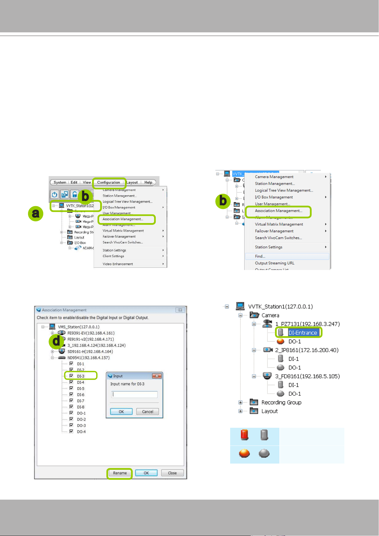
VIVOTEK - A Leading Provider of Multimedia Communication Solutions
User's Manual - 159
How to Set up Association Management
VAST LiveClient supports association management which allows the user to congure relative
event trigger notications of connected network devices. (E.g., DI/DO status on the hierarchical
management tree, motion detection windows appear in the video cell, the event list in the event
window)
Association Management
Please follow the steps below to congure assocation settings:
a. Select the station from the hierarchical management tree.
b. Click
Configuration > Association Management
on the menu bar (or
right-click
the station and
select
Association Management
).
c. The
Association Management
window will prompt. Select or deselect the items and click
Save
to enable the settings. The items you've selected will also be displayed under the hierarchical
management tree.
For example:
d. If you want to rename the DI device, select the DI item and click the
Rename
button. It will be very
convenient for you to recognize the target DI device.
/
Digital input on / off
/
Digital output on / off
a
b
b
d
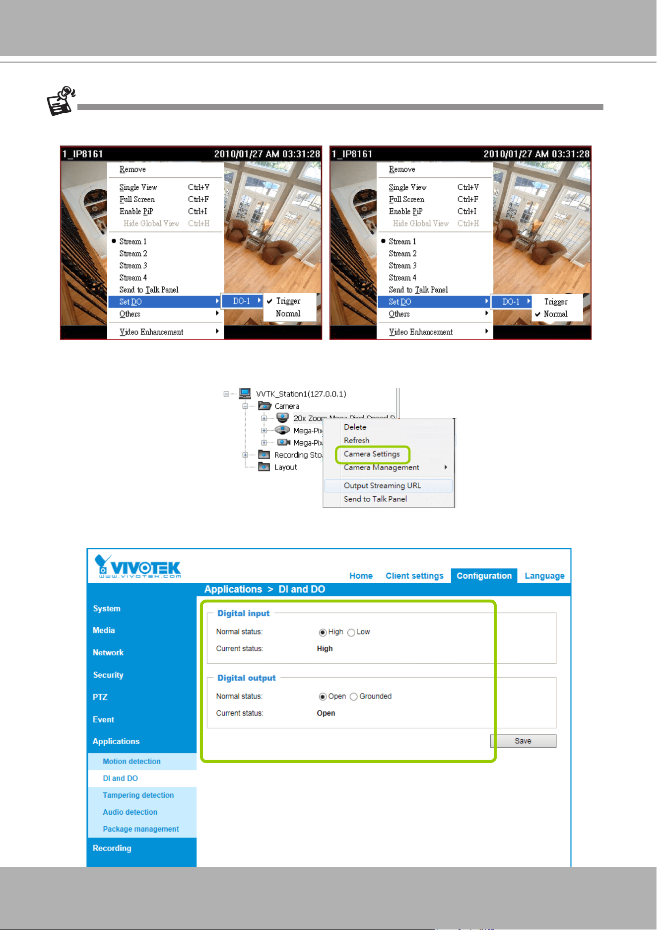
VIVOTEK - A Leading Provider of Multimedia Communication Solutions
160 - User's Manual
To manually enable DI/DO settings, please
right-click
the video cell and select
Set DO
to enable (
Trigger
) or
disable (
Normal
) the digital output of the linked device.
Before you congure the DI/DO Settings for VAST, please enable DI/DO settings on your network device and set
up the camera correctly on the conguration page. You can
right-click
the device and click
Camera Settings
to
open the conguration page.
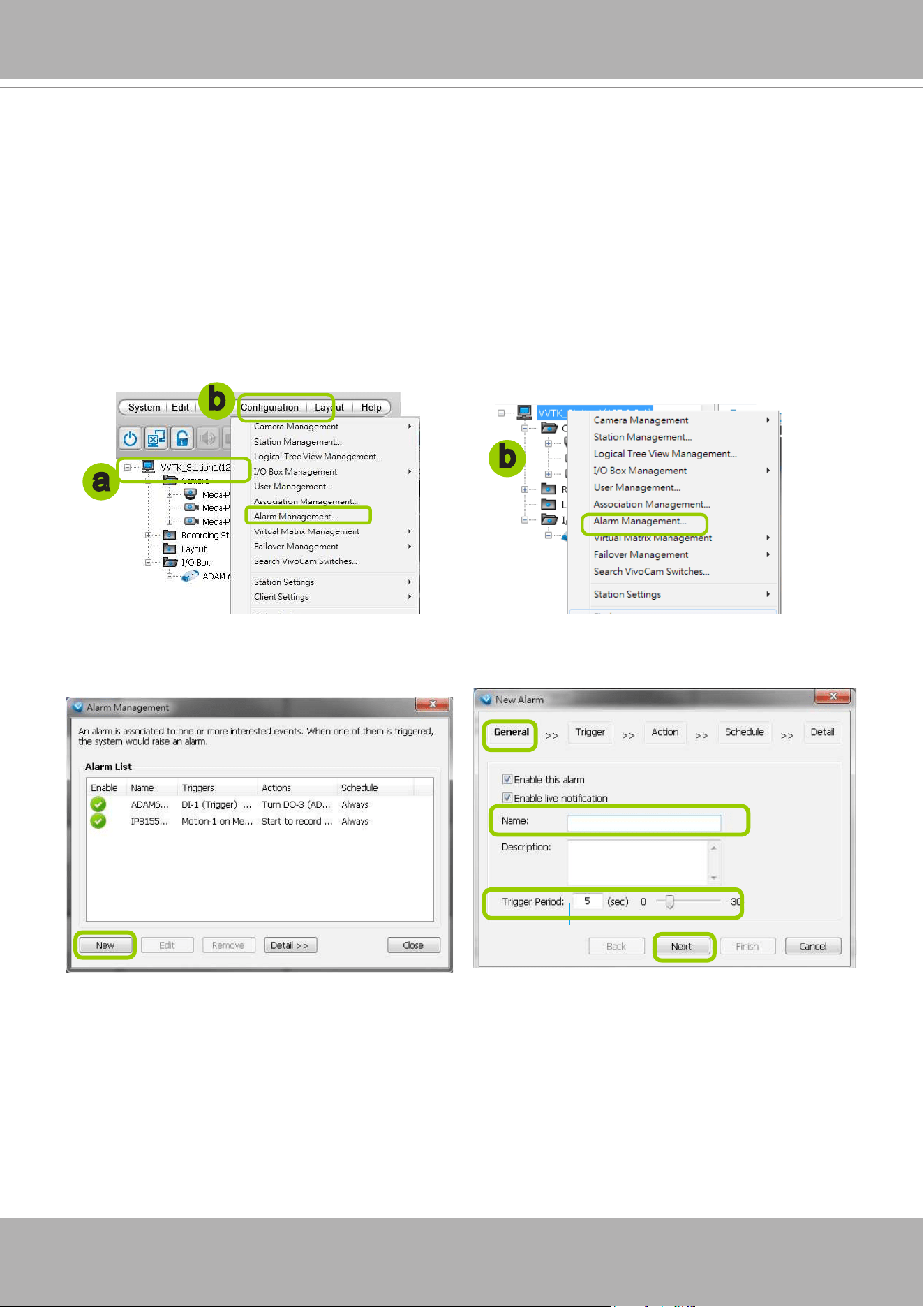
VIVOTEK - A Leading Provider of Multimedia Communication Solutions
User's Manual - 161
How to Set up Alarm Management
VAST LiveClient supports Alarm management which allows the server to display and respond to
particular situations (events).
Alarm Management
Please follow the steps below to congure Alarm management:
a. Select the station from the hierarchical management tree.
b. Click
Configuration > Alarm Management
on the menu bar (or
right-click
the station and select
Alarm Management
).
c. The
Alarm Management
window will prompt. Click
New
to congure a new event. Enter a name and
description for the new alarm. When you nish the general settings, click
Next
to set up trigger source
settings. The Alarm name you specify here will be displayed on the Alarm panel in the Live view.
a
b
b
Detect next event after 5 secs
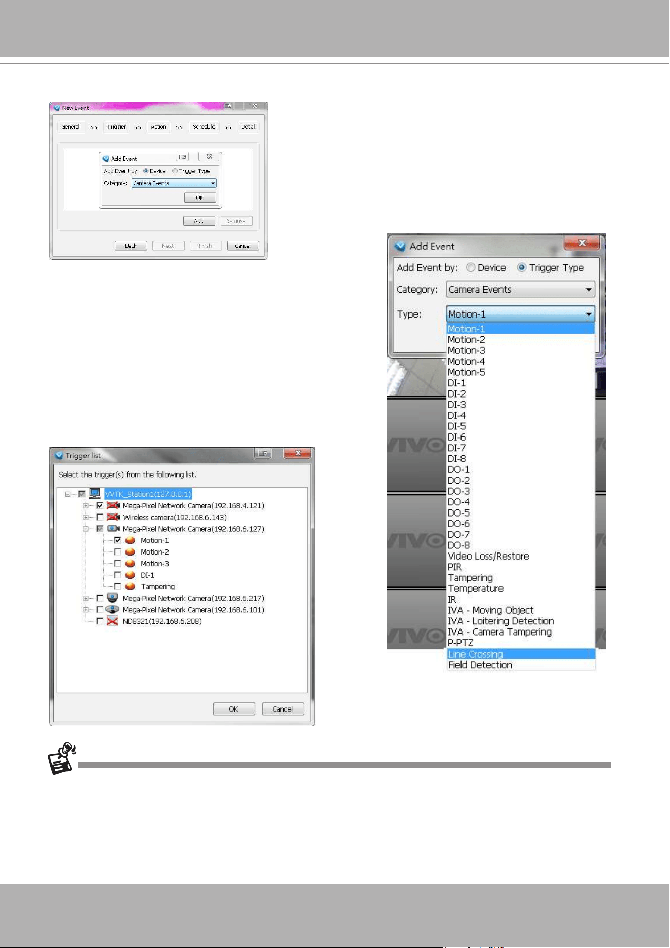
VIVOTEK - A Leading Provider of Multimedia Communication Solutions
162 - User's Manual
d. Click
Add
to select the trigger source by Device or Trigger Type.
Note that the
Motion detection
windows are separately
congured using web consoles with each individual
cameras. Open a web console with the camera to congure
Motion detection windows.
The Storage Status includes: Storage connection status
and storage capacity status on NVR systems.
Each individual motion detection window can be used as a
triggering condition. The Line Crossing and Field Detection
packages running on cameras also apply as triggers.
If you connect your DI/DO devices via an I/O module (I/O box), please refer to page 357,
Appendix E
Support for Digital I/O Modbus TCP Modules
for details.
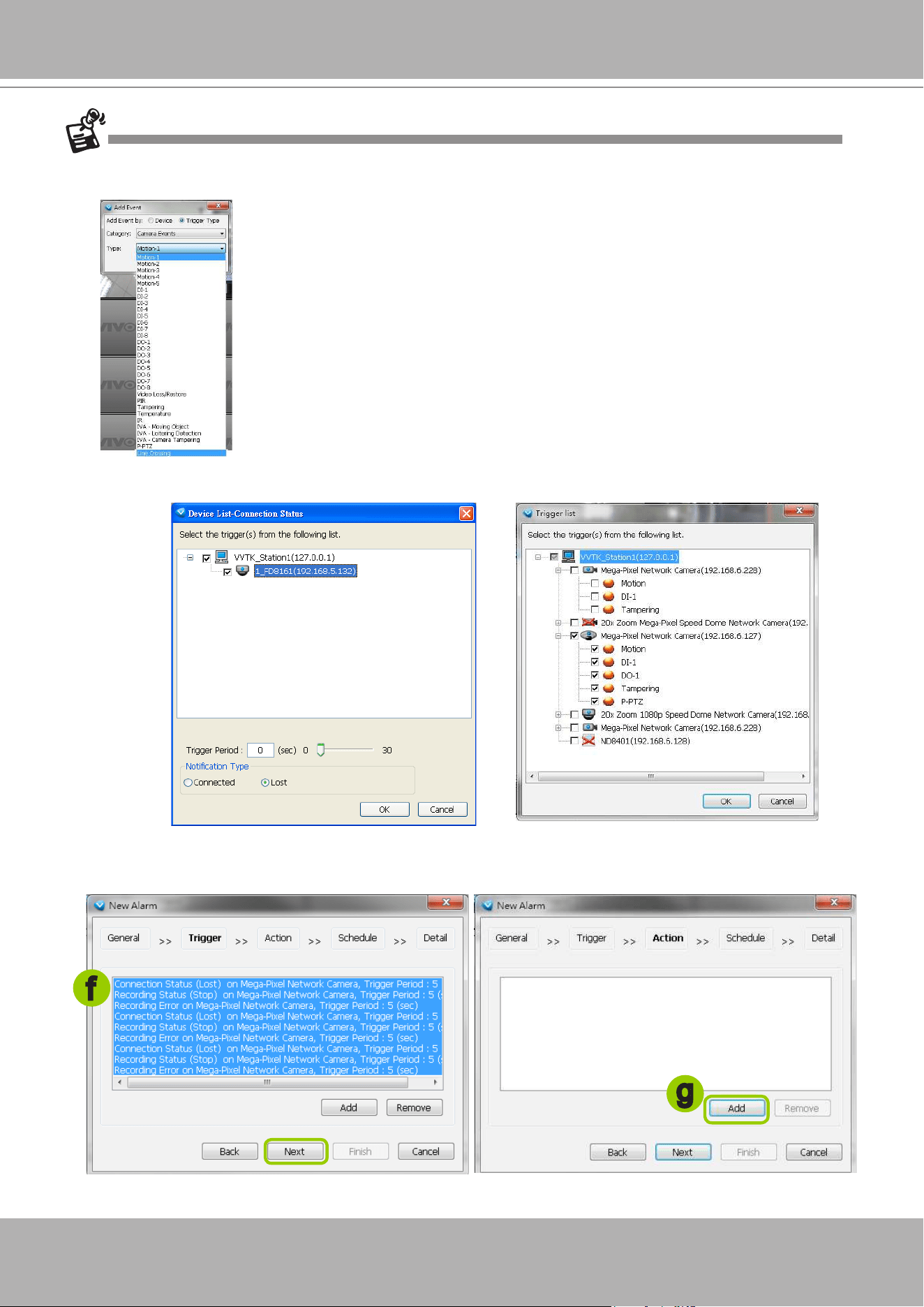
VIVOTEK - A Leading Provider of Multimedia Communication Solutions
User's Manual - 163
e. The Device List window will prompt. Select one or more devices and set the Notification Type.
Depending on the trigger source, the Notification Type will be different. Then click
OK
to close the
window.
f. The trigger source(s) will be listed on the window as shown below. If you want to add more Trigger
sources, click
Add
and repeat steps d. to e. Then click
Next
to assign action(s) to the trigger source(s).
g. Click
Add
to open the
Action
Settings window.
f
g
There is a new event trigger type, P-PTZ. The P-PTZ refers to the occurrence of Auto Tracking action in
a Panoramic PTZ conguration.
Auto Tracking is congured on the sheye camera in a Panoramic PTZ
conguration.
If you manually congure a detection area for the Auto Tracking function,
the P-PTZ event will not be triggered.
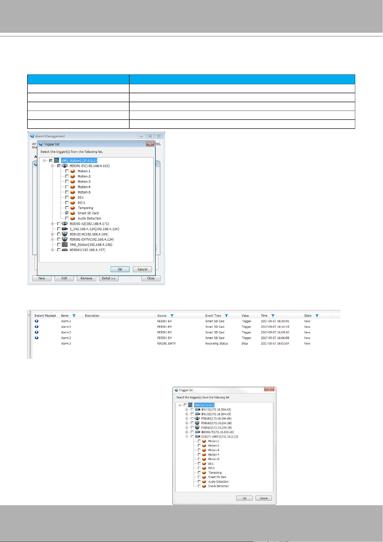
VIVOTEK - A Leading Provider of Multimedia Communication Solutions
164 - User's Manual
Note that if your camera is using Sony's SR-WM series cards, SD card status events can be used as a
trigger.
The event messages look like the following:
Warning Error Message Examples
Normally Functioning The SD card is inserted and there is enough lifespan remaining.
Replacement Recommended Has reached xx% of the SD card's lifespan.
Has Reached its Lifetime All the spare blocks have been consumed. The card is read-only.
Card Not Inserted No SD card is inserted.
Failed to Get Status Unexpected error has occurred.
The related event messages will prompt on the event list. On seeing the Smart SD events, you
should replace your SD card.
The Tampering, Audio Detection, and Shock Detection are also available as a trigger source
with cameras that support these features. Shock Detection is available for cameras that come
with an acceleration sensor.
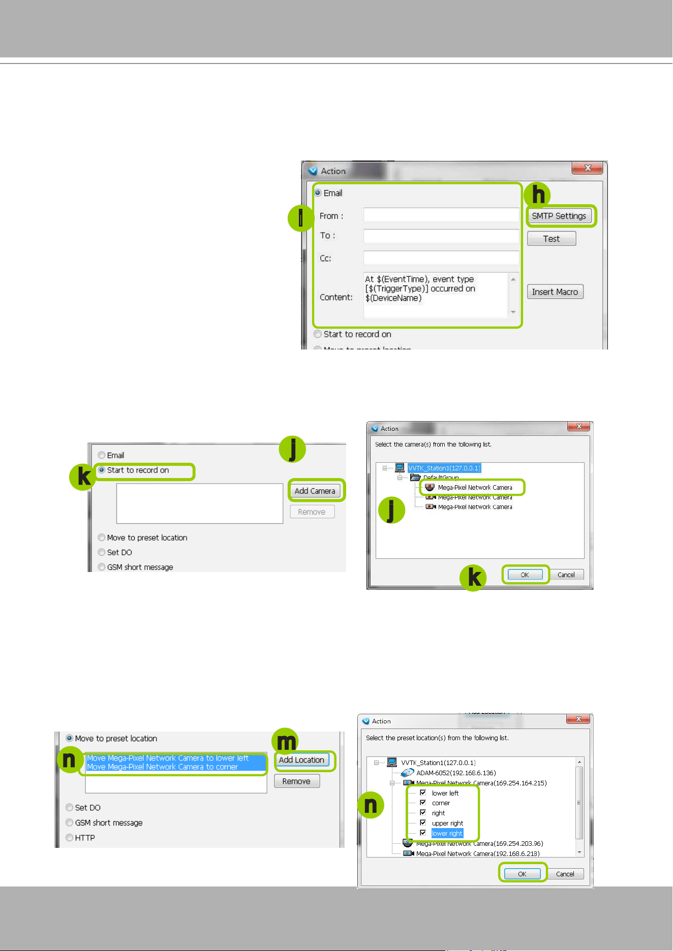
VIVOTEK - A Leading Provider of Multimedia Communication Solutions
User's Manual - 165
Start to record on: The sever will start to record video from selected camera(s) when an event is
triggered.
j. Click
Add Camera
to select the target camera(s).
k. The selected camera(s) will be listed on the left window below. When completed, click
OK
on the
bottom to enable the setting.
Move to preset location: The target camera(s) will move the shooting area to the preset location(s)
when an event is triggered.
l. To enable this function, please congure some preset locations on the camera conguration page
rst.
m. Click
Add Location
to select preset location(s).
n. The selected preset location(s) will be listed on the left window below. When completed, click
OK
on
the bottom to enable the setting.
j
j
k
m
n
n
k
There are several types of Action Settings.
Email: The sever will send a notication via e-mail when a trigger is activated.
h. To enable this function, please set up the SMTP server rst. Click
SMTP Setting
to open the window
and refer to page 215 for detailed information.
i. Enter the related informtaion. You can modify the mail content in the blank. If you want to modify the
content, click
Insert Macro
to select the parameter. When completed, click
OK
on the bottom to
enable the setting.
h
i
Note that you can insert a snapshot
taken by the time of alarm occurence
of the recorded video. The snapshot
will be sent along with the notication
Email. The snapshot comes from
camer's stream 1.
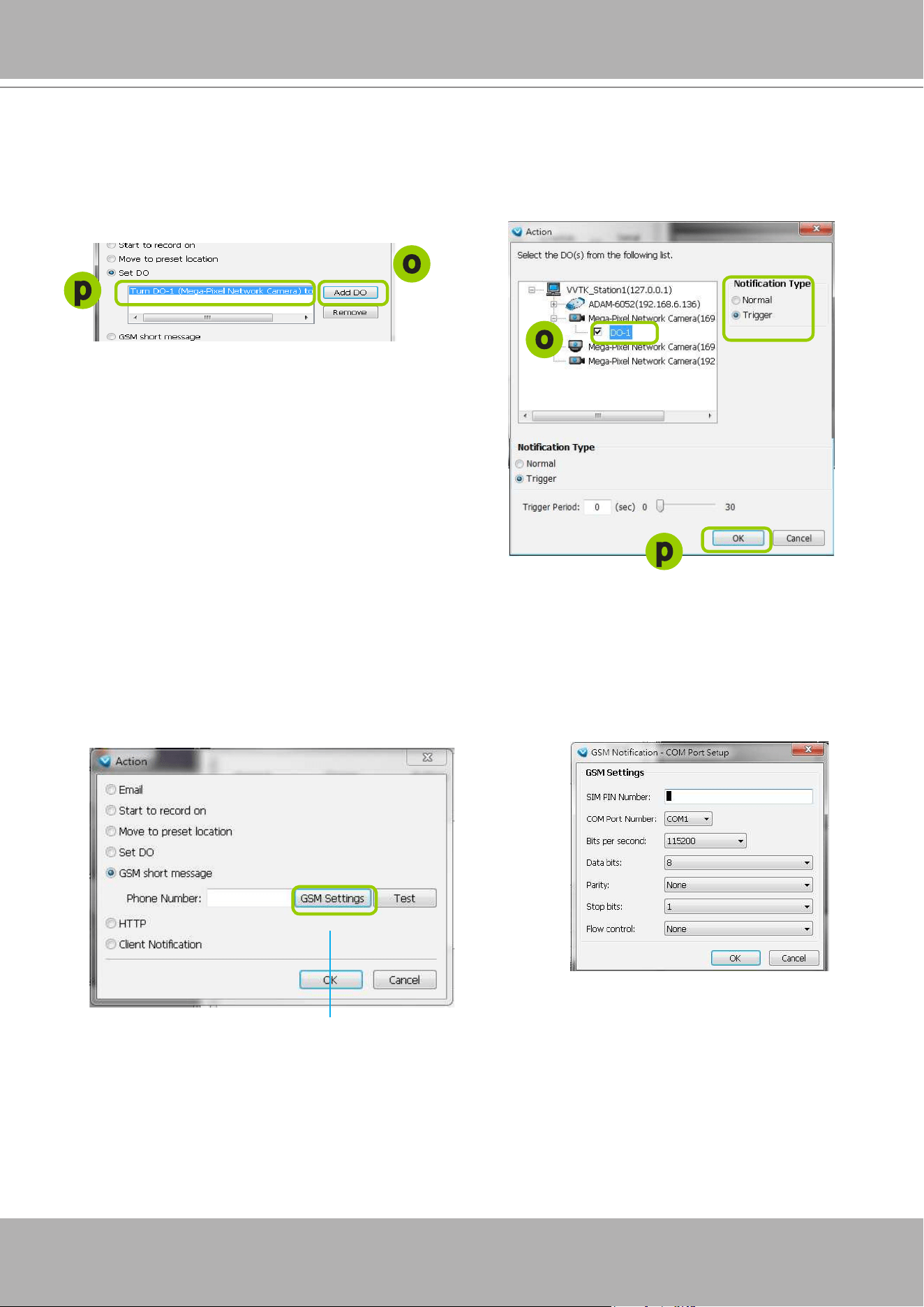
VIVOTEK - A Leading Provider of Multimedia Communication Solutions
166 - User's Manual
GSM Short Message: The sever will send a short message to a GSM cell phone when an event is
triggered.
q. Please enter the Phone Number and open
GSM Settings
window to set related information if
necessary. When completed, click
OK
to enable the setting.
Please enter the country code if you use overseas call.
Set DO: Select this option to turn on external digital output device(s) when an event is triggered. For
more information about how to set DI/DO settings on the target camera, please refer to page159.
o. Click
Add DO
to select DO device(s) and select a DO status (Normal or Trigger).
p. The selected DO device(s) will be listed on the left window below. When completed, click
OK
to
enable the setting.
o
o
p
p
Select the Tirgger Period from the slide bar below.
The range is 0 to 30 seconds. The DO trigger
signal will return to normal after after this period of
time.
Note that the Trigger Period setting does not apply
to the camera DI/DO managed by substations.
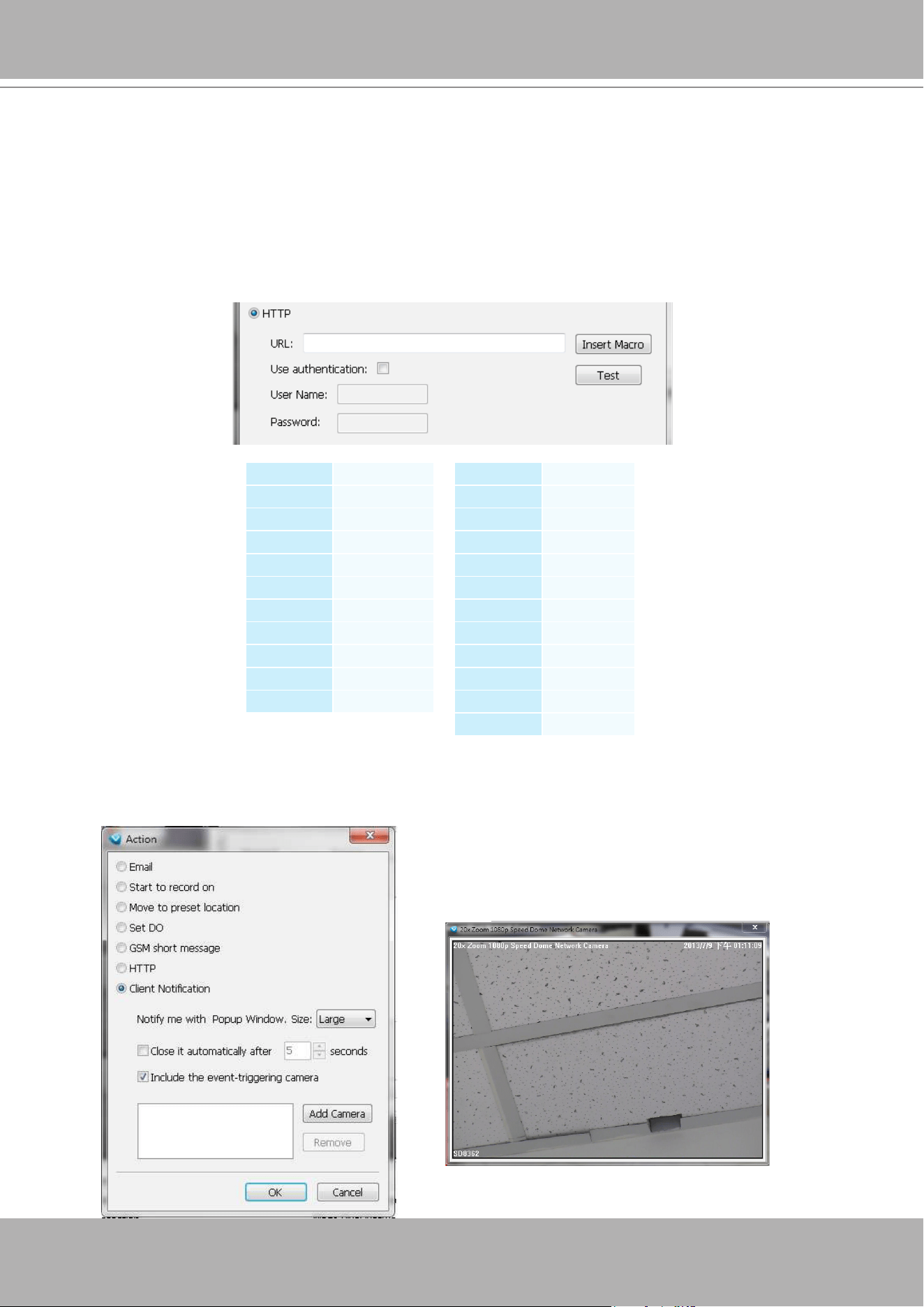
VIVOTEK - A Leading Provider of Multimedia Communication Solutions
User's Manual - 167
Client Notification: On the occurence of an event, a pop-up window will display to show what is
triggering the current event. Select the window size, and select the display duration of the notication
window. If not selected, the notication window is manually closed.
HTTP: This function allows user to send a CGI command to the linked network camera, such as pan/
tilt/zoom function or enable DO devices.
r. You can click
Insert Macro
to select the parameter. Please enter authentification information
if necessary. For example: http://192.168.3.66/cgi-bin/admin/setparam.cgi?system_
hostname=$(EventTime) $(CameraName)
If you want to use special characters such as $-_.+!*'(),#%+$,@:;/?=&, please refer to the
following table to transfer the Code (Hex).
For example: http://192.168.3.66/cgi-bin/admin/setparam.cgi?system_hostname=123
&456
--> http://192.168.3.66/cgi-bin/admin/setparam.cgi?system_hostname=123%26456
Character Code (Hex)
! 21
# 23
$ 24
% 25
& 26
' 27
( 28
) 29
* 2A
+ 2B
Character Code (Hex)
, 2C
- 2D
. 2E
/ 2F
: 3A
; 3B
= 3D
? 3F
@ 40
_ 5F
~ 7E
Include the event triggering camera: You can select to
display the screens of other cameras (e.g., cameras
that are closely adjacent) when the notification
prompts.
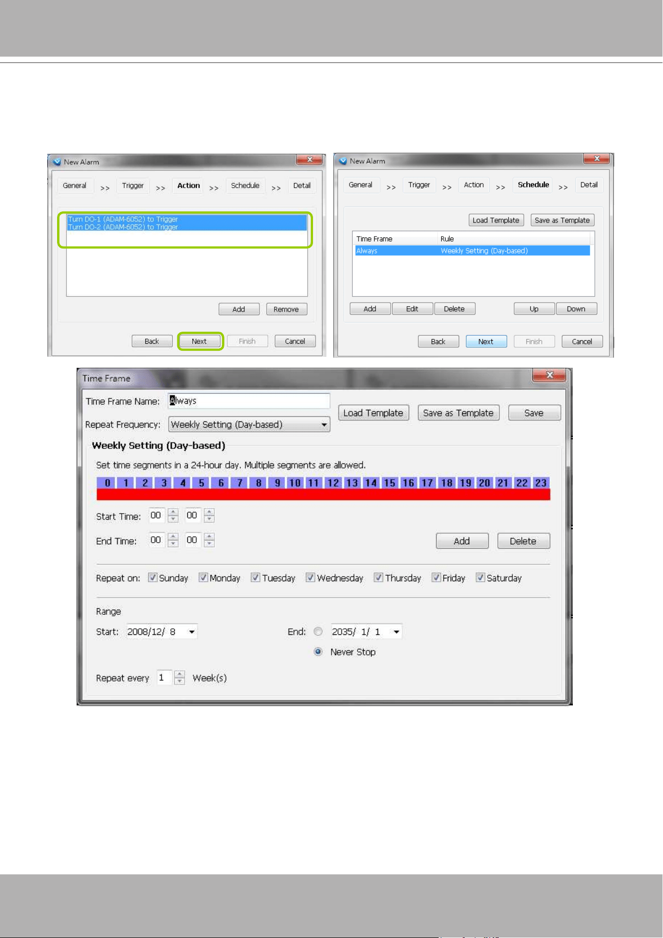
VIVOTEK - A Leading Provider of Multimedia Communication Solutions
168 - User's Manual
s. The action(s) will be listed in the window as shown below.
Then click
Next
to set up schedule(s) to the action(s).
For more information about
Schedule Settings
, please refer to Recording Schedule Settings on page
191. You can assign more than one time frame to one action.
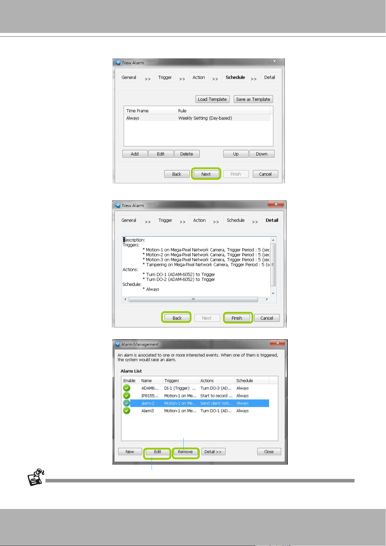
VIVOTEK - A Leading Provider of Multimedia Communication Solutions
User's Manual - 169
t. When you finish schedule settings, click
Next
to review the detailed information of the new event
settings.
u. Following is the detailed information of the new event setting. You can click
Back
to modify the event
setting or click
Finish
to close the window.
v. Following is an example of an enabled event. You can click
New
to set up more events or click
Close
to exit the window.
If your target station has sub-station(s), the
trigger sources
can be selected from the device(s) under
the sub-station(s); while the
actions
can only be performed on the device(s) under the target station.
Click to disable or modify the selected event
Click to remove the event
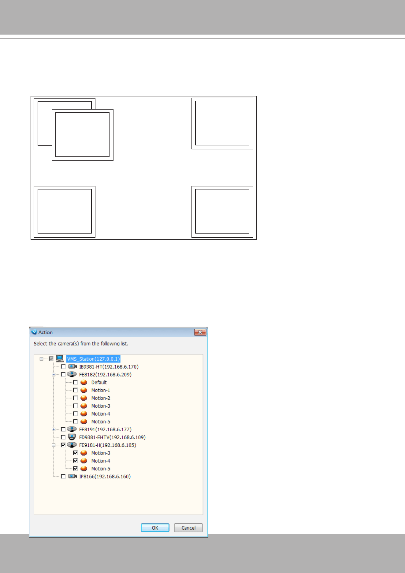
VIVOTEK - A Leading Provider of Multimedia Communication Solutions
170 - User's Manual
Alarm notification
1
Alarm notification
2
Alarm notification
3
Alarm notification
4
Alarm notification
5
With multiple alarms simultaneously triggered, the notication windows will appear consecutively at the
four corners of the screen. With more than 4 alarms, the latter notications will appear on top of the old
ones at a slightly shifted position.
Fisheye Motion Windows
When fisheye cameras are configured with Motion Detection windows and their motion events are
triggered in the notication windows, they display in a more comprehensive dewarped, regional view.
If the Alarm triggering condition is congured as DI (digital inputs) or other inputs, you can congure the
Alarm Action as displaying Client Notication as well. You can select the "Include the event-triggering
camera," to display the pre-congured motion windows. The sheye cameras' motion windows display in
the dewarped mode.
Alarm Notication Windows
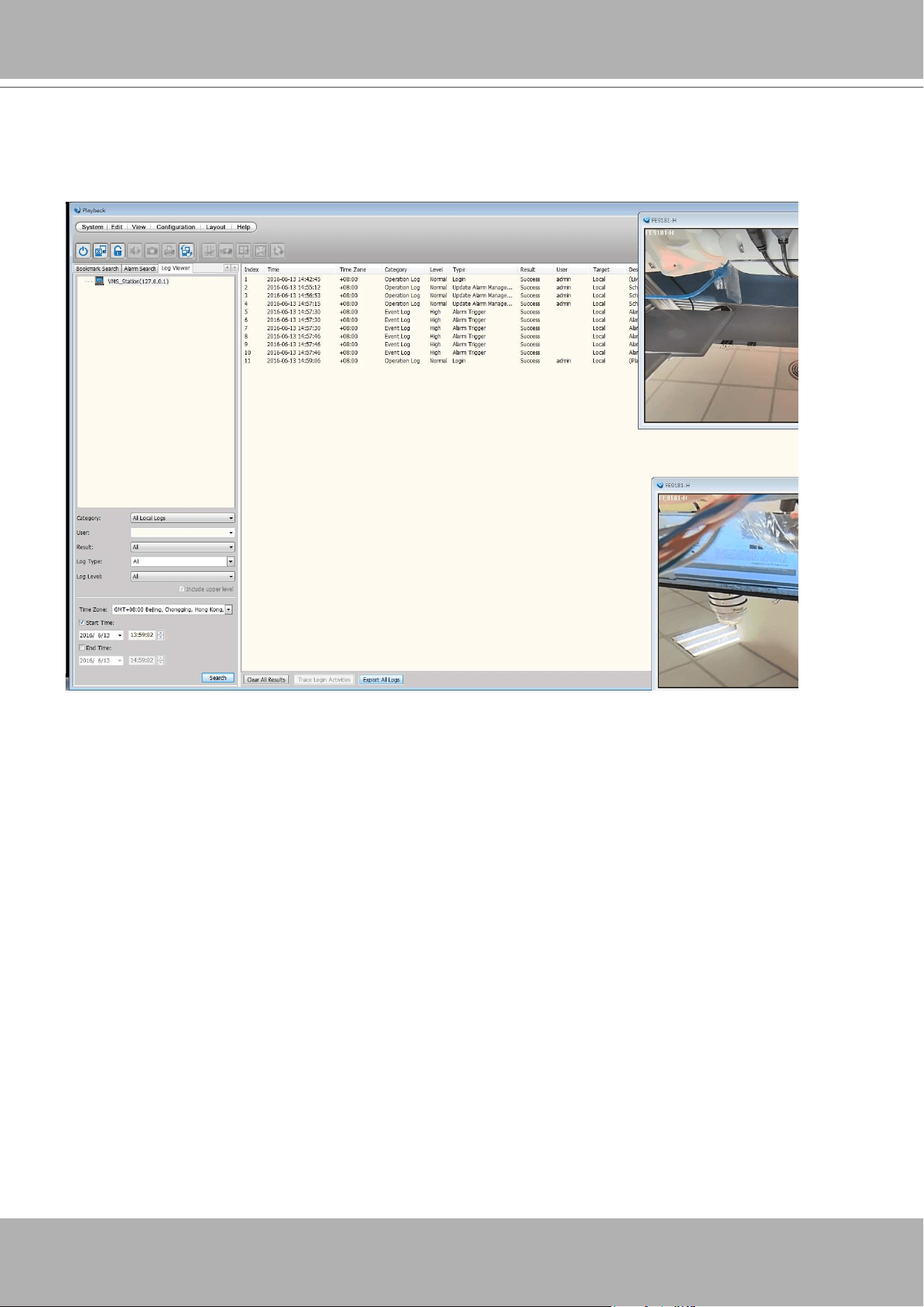
VIVOTEK - A Leading Provider of Multimedia Communication Solutions
User's Manual - 171
Export All Logs
In the Playback utility, you can select the Log Viewer tab window, display the past events, and export all
event logs to a CSV le.
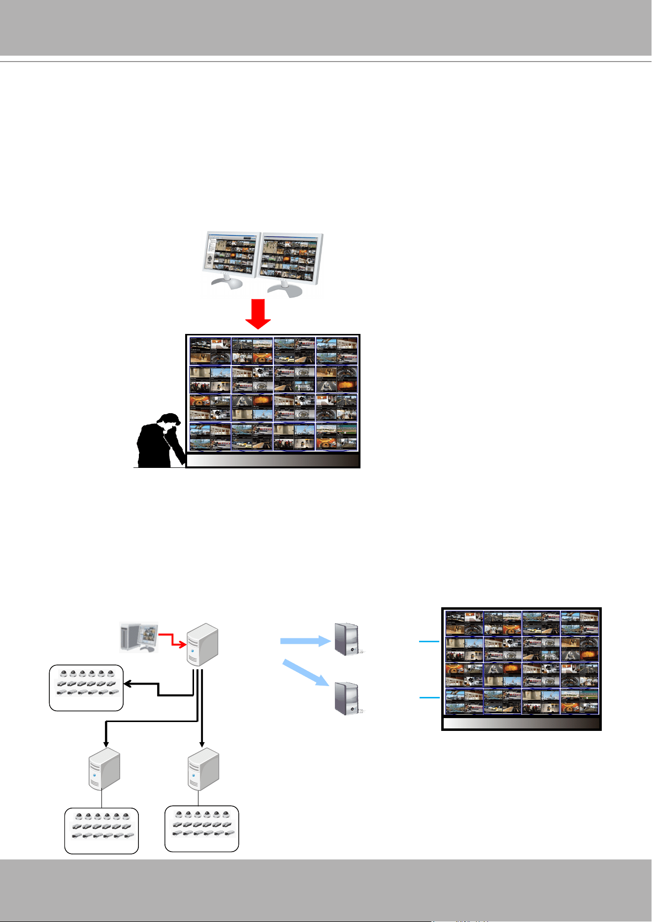
VIVOTEK - A Leading Provider of Multimedia Communication Solutions
172 - User's Manual
How to Manage the Virtual Matrix
Virtual Matrix is a very useful tool for multiple monitor display and management. Based on the
whole surveillance system architecture, it efciently helps user construct a real-time live video
wall in the control center. Under a large-scale hierarchical system, through VAST LiveClient
you can only simultaneously monitor up to 128-CH on dual monitors; while Virtual Matrix offers
fully extension for numerous channels and screens, thus making VAST a very powerful central
management system. Moreover, you can change the layout to 2x2 or 3x3 on each monitor
to enlarge the video size, then display the video pages on saperate monitor for close-up
monitoring.
The architecture of VAST Matrix
As shown below, the surveillance system architecture is composed of VAST LiveClient, VAST Server with
two sub-stations, and VAST Matrix separately on individual hosts. Before constructing the Virtual Matrix,
please install and run VAST Matrix Program on Matrix Recipient connected with the video wall. Through
the Virtual Matrix connection, you can use LiveClient to log in the root server to remotely manage and
display all the live view onto the video wall by easily drag-and-drop. PTZ control is also available as on
the LiveClient.
VAST-64-CH on dual monitors
Video Wall of Virtual Matrix
VAST Server
(Root Station)
VAST
LiveClient
VIVOTEK IP CameraVIVOTEK IP Camera
VIVOTEK IP CameraVIVOTEK IP Camera
VIVOTEK IP CameraVIVOTEK IP Camera
VAST/ST7501 Server
(Sub-station)
VAST Matrix
Recipient 1
VAST Matrix
Recipient 2
Video Wall
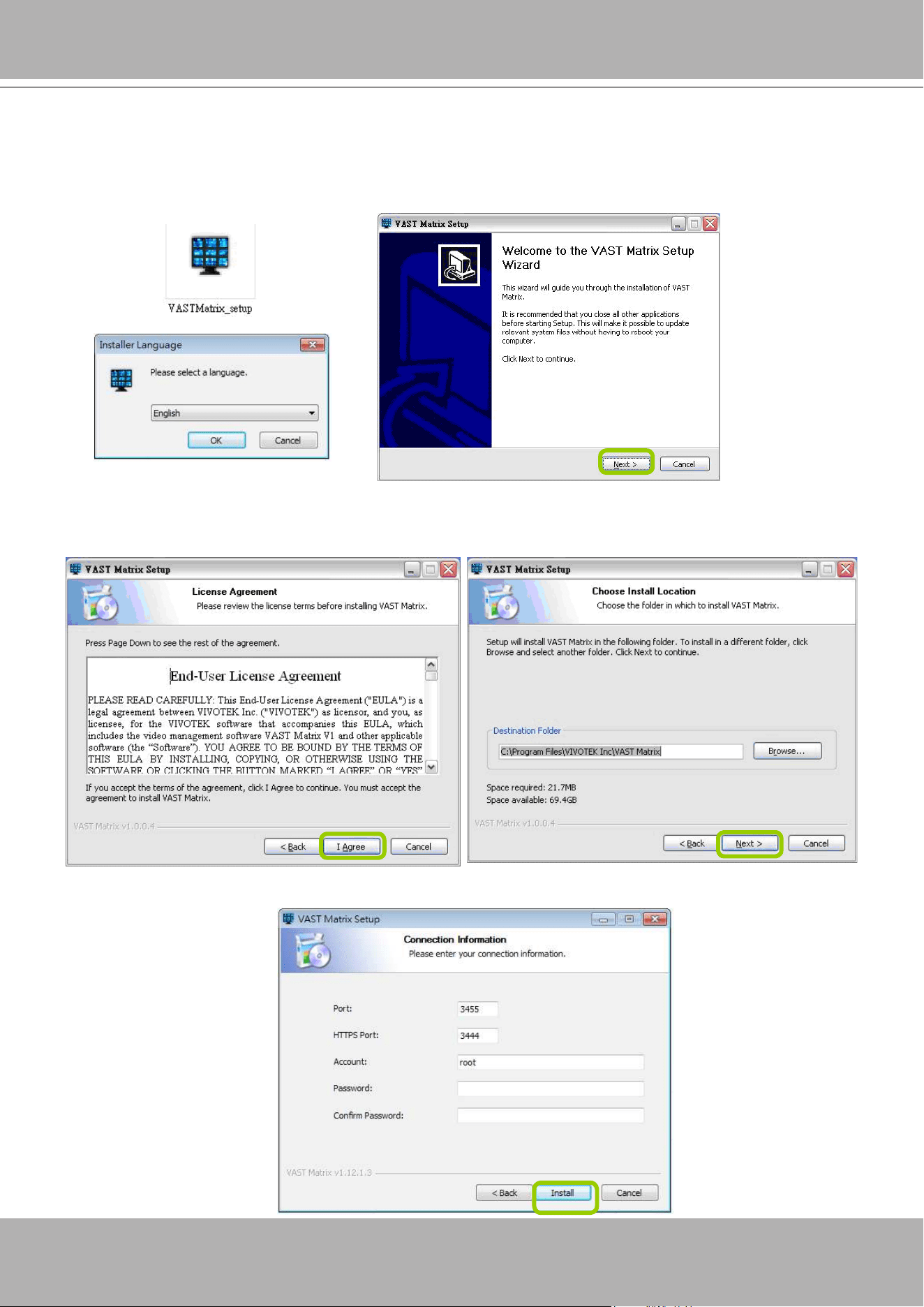
VIVOTEK - A Leading Provider of Multimedia Communication Solutions
User's Manual - 173
Installing VAST Matrix Program
Please follow the steps below to install VAST Matrix Program:
a. Run
VASTMatrix_setup.exe
on another host (Matrix Recipient). Then click
Next
to start installation
wizard.
b. Carefully read to accept the End-User License Agreement for use. Click
I Agree
to the next step.
c. Choose the installing path as the destination folder, the required space and available space of the hard
disk will be shown below for reference. Click
Next
to the next step.
d. Fill in the connection information with Port, Account & Password for VAST Server to connect to the
Matrix Recipient.
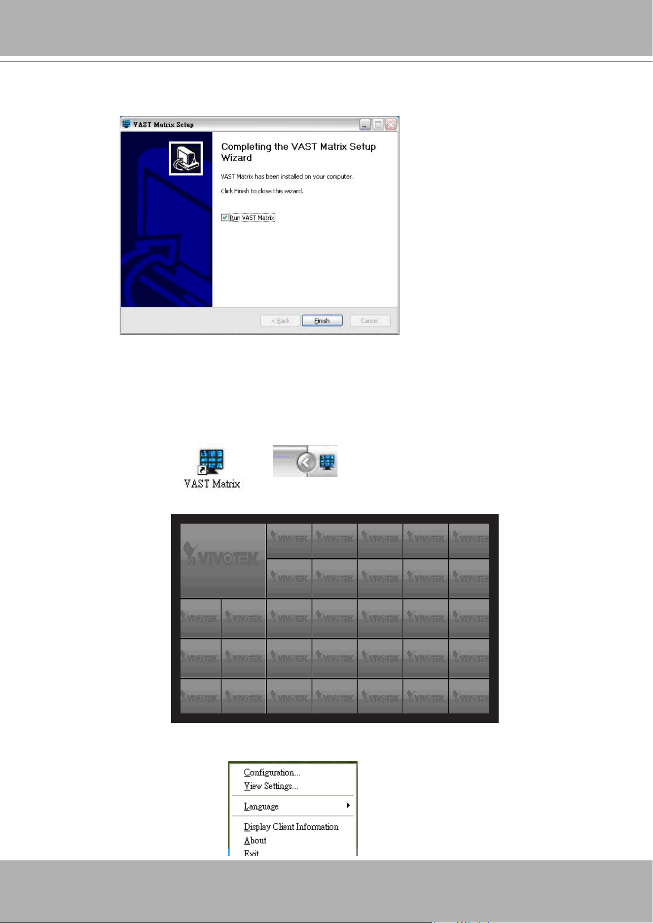
VIVOTEK - A Leading Provider of Multimedia Communication Solutions
174 - User's Manual
e. Click
Finish
to close the installation wizard, and you might want to run VAST Matrix immediately after
installation by selecting the option
Run VAST Matrix
.
Launching VAST Matrix
Please follow the steps below to install VAST Matrix Program:
a. Click the desktop icon to start VAST Matrix. When it’s begun running, there will be a VAST Matrix tray
icon on the toolbar for the user to congure easily.
b. The VAST Matrix live view window with multiple types of layout will be displayed. The following shows
32-channels layout.
c.
Right-click
on the live view window, a function menu will pop up. You may also open the menu by
right-click on the tray icon.
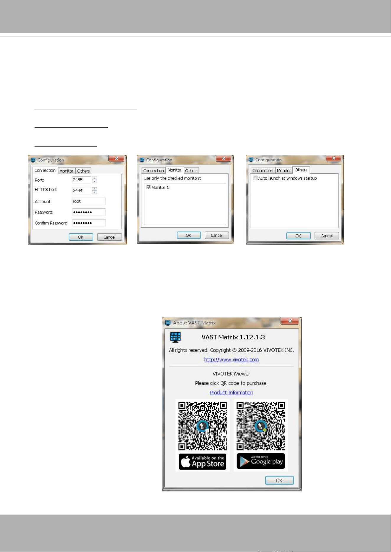
VIVOTEK - A Leading Provider of Multimedia Communication Solutions
User's Manual - 175
Conguration
Connection: Enter the account, password and port information for the VAST Recipient.
Monitor: It shows the monitor(s) connected to your host. You can select the monitor(s) you wish to
display as the video wall.
Others
Auto launch at windows startup: Select this option if you want VAST Matrix to launch when windows
starts up in case to avoid the computer reboots by itself and accidentally shuts down VAST Matrix.
Display key frame only: Select this option to display live video with the key frame only in order to save
the bandwidth. It also lowers down the CPU loading and memory usage.
Enable de-interlace: Select this option if your linked device does not support de-interlace function. For
example: VS7100.
View Settings
Please refer to page 237 for detailed illustration.
About
This dialog that shows the version of VAST Matrix and the simple statement of the version copyright.
Exit
Click to close the VAST Matrix.
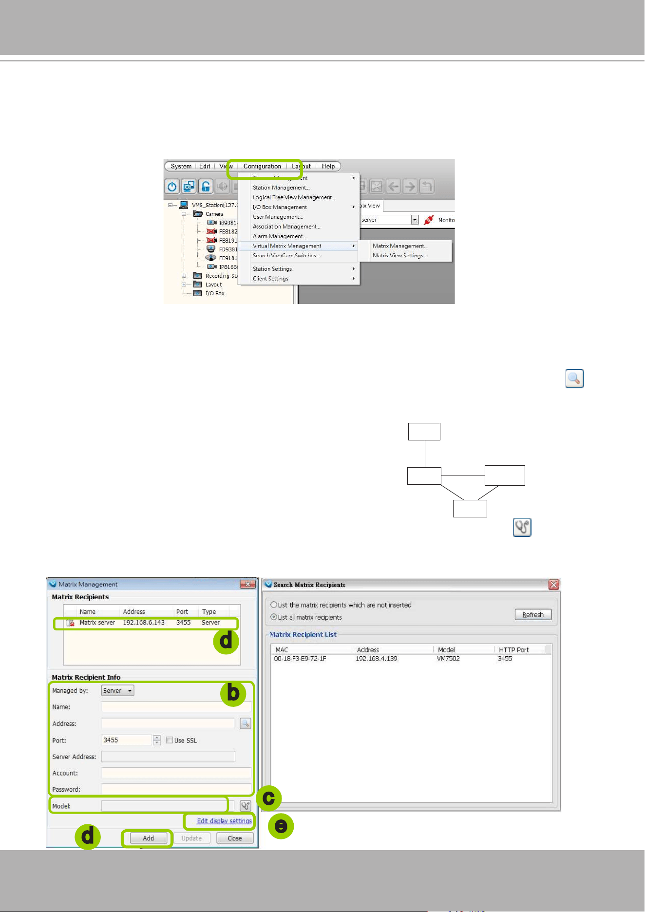
VIVOTEK - A Leading Provider of Multimedia Communication Solutions
176 - User's Manual
VAST Matrix Management
Once the VAST Matrix Program is setup completely, the next step is to connect the VAST Server with
VAST Matrix Recipient(s). Use LiveClient to log in VAST Server, then click
Configuration
>
Virtual
Matrix Management
to congure Matrix Management and Matrix View Settings.
Matrix Management Settings
Please follow the steps to set up VAST Matrix Recipient(s):
a. Click
Configuration
>
Virtual Matrix Management > Matrix Management
to open the Matrix
Management window.
b. Manually enter the Matrix Recipient Info as previous settings, or you click the search button to
search for the Matrix Recipient(s) on the LAN.
The Managed by menu allows you to let a LiveClient instance manage the Matrix conguration. In
normal uses, the conguration is managed by the VAST server.
b
c
d
d
e
c. When the information of the target recipient is lled in, you can use the detect button to conrm if
the lled information is correct.
d. Click
Add
, then the recipient will be displayed on the Matrix Recipients list window.
VAST CMS
Matrix
VAST
Server
VAST
LiveClient
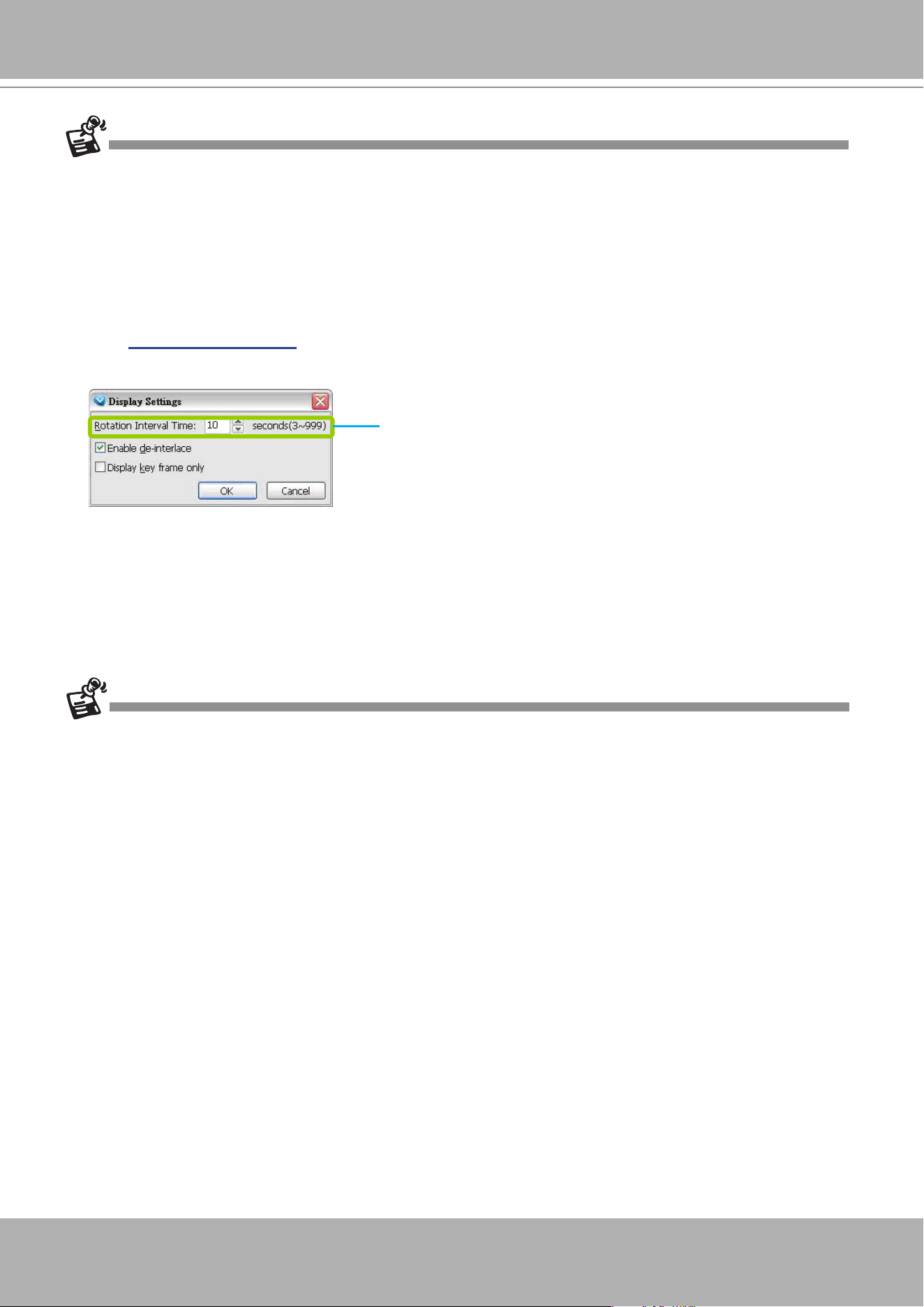
VIVOTEK - A Leading Provider of Multimedia Communication Solutions
User's Manual - 177
When entering a server address, please avoid entering the XML-related characters: <, >, &, ', and ".
The Matrix View display is capable of executing rotation. The
default interval time is set at 10 seconds.
f. If you want to set up more Martrix Recipients, repeat the above steps.
g. If you want to modify the Recipient Info, select it from the list to change settings, then click
Update
to
enable the new settings.
h. When all settings are done, click
Close
to exit the Matrix Management page.
e. Click
Edit display settings
to set up the viewing interface for the monitors (video wall) connected to
the Matrix Recipient host.
Due to the limitations imposed by the Windows UAC (User Account Control), you need to right-click on
the Matrix icon to display and "run as administrator," after you close and re-start the Matrix utility.
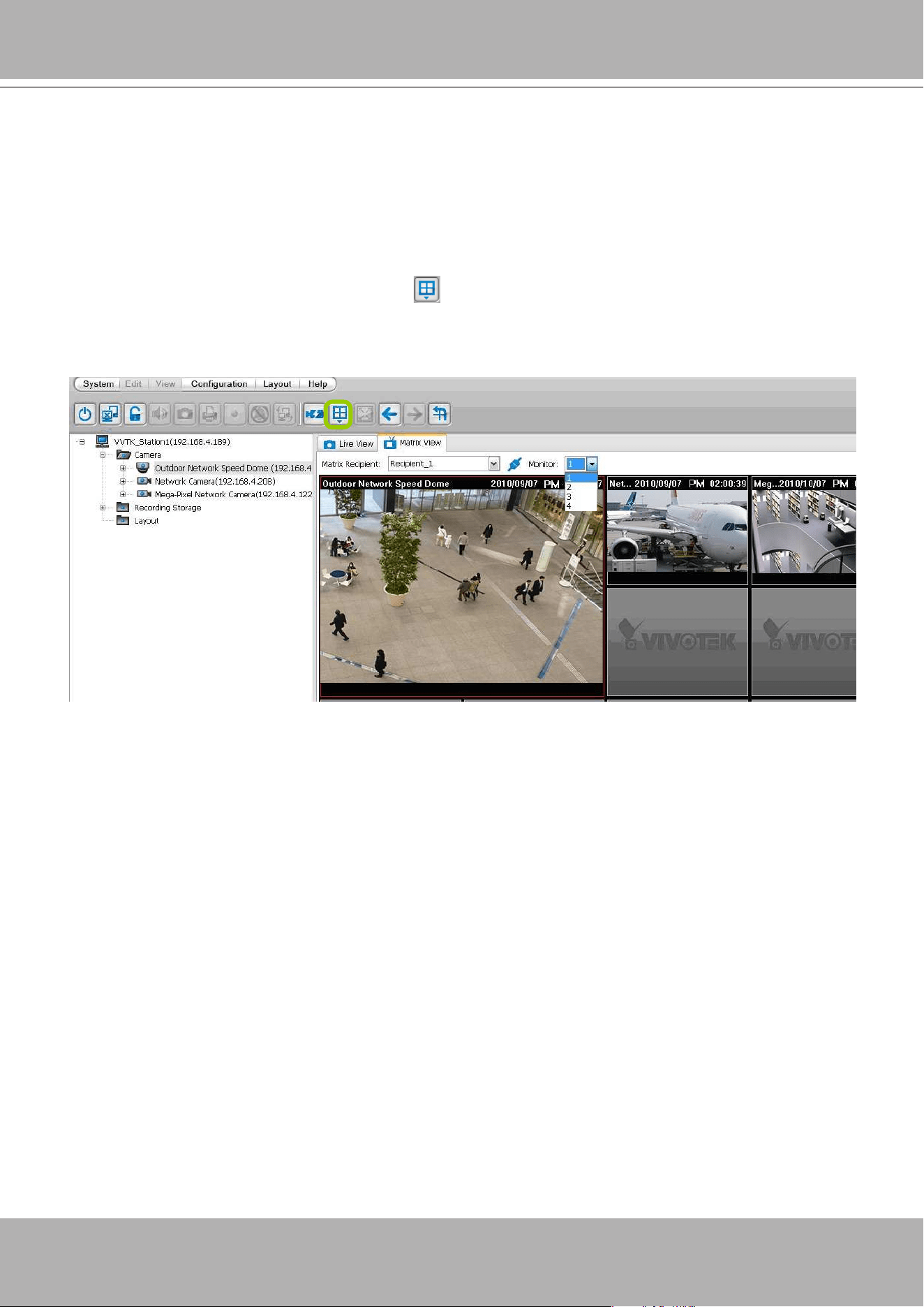
VIVOTEK - A Leading Provider of Multimedia Communication Solutions
178 - User's Manual
Manage VAST Matrix through VAST LiveClient
Once the setup is complete in Virtual Matrix Management, you may go back to the main page of
LiveClient, the connection between VAST Server and VAST Matrix will be working successfully. Then
you can choose Matrix Recipient and the monitor from the drop-down list for the operation control. Some
buttons on the quick access bar will be disabled when you switch from the Live View Panel to Matrix
View Panel.
Change the layout
As the following picture shows, you can click
to change the layout and set new layout group on the
Matrix View Panel using the methods same on the use of the LiveClient. The layout on the monitor (video
wall) will also change synchronizely once you change the layout on Matrix View Panel.
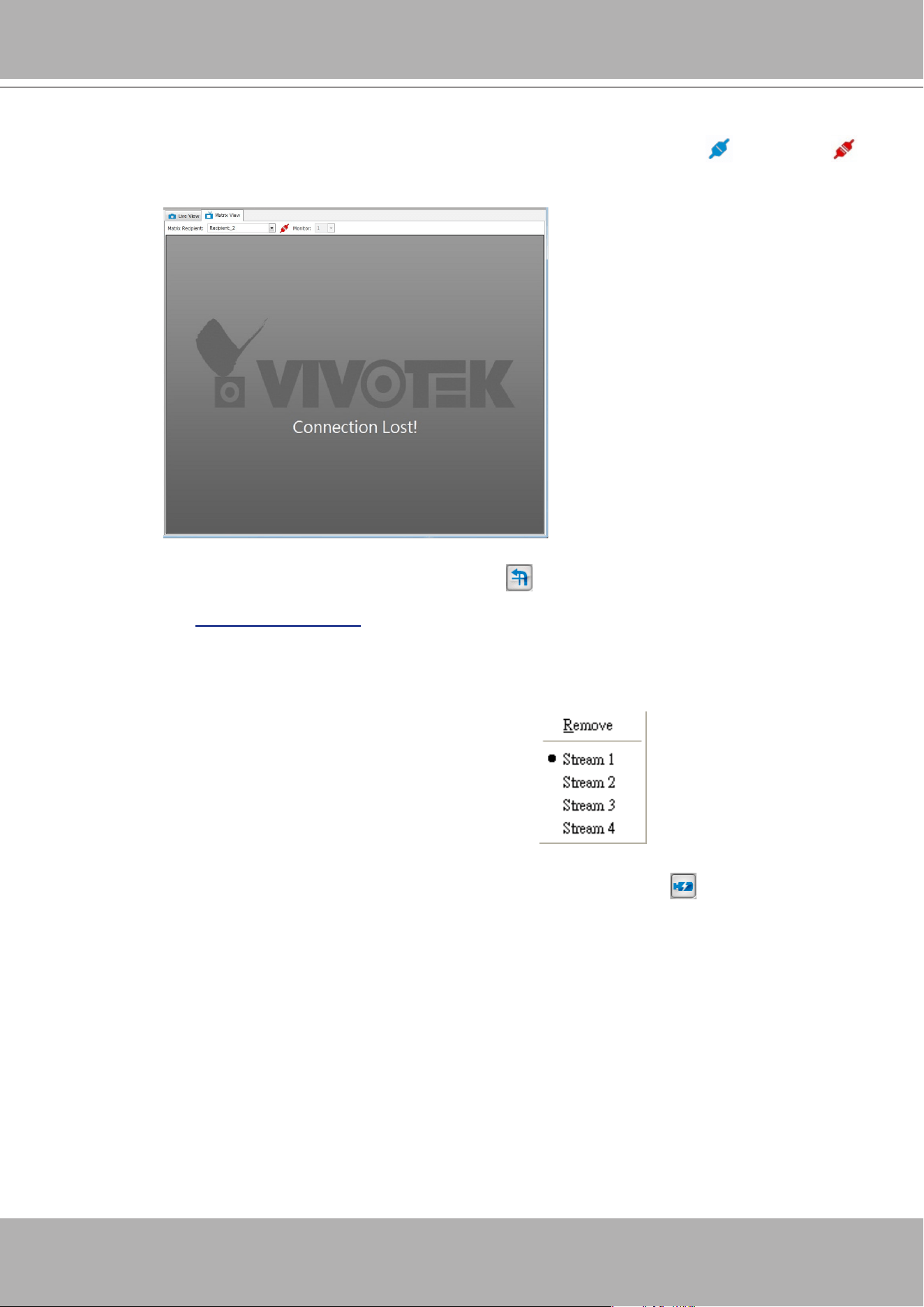
VIVOTEK - A Leading Provider of Multimedia Communication Solutions
User's Manual - 179
Rotation
VAST Matrix is capable of executing rotation by clicking
. You can even select another layout group
on the Matrix View window without stopping the rotation. If you want to adjust the rotation interval time,
please refer to
Edit display settings
on page 176 for adjusting.
PTZ
VAST Matrix currently does not support PTZ control.
Matrix View Menu
Right-click on the window to open the menu.
Remove: Remove the channel from VAST Matrix.
Stream 1 ~ 4: Switch the camera stream between 1 ~ 4.
Remove All Connections
It’s capable of removing all connections from VAST Matrix once by clicking on
button.
Matrix View Settings
Click
Conguration
>
Virtual Matrix Management > Matrix View Settings
to open the window.
Media Source
You can choose the path of media source from camera directly or the CMS server to display on Matrix
View.
Connection status
If the VAST Server is not able to connect to the Matrix Recipient, the status icon
will become
and show the reason of disconnecting when you slide the mouse to the connection status icon. The
"Connection Lost" string will be displayed on the Matrix View window as shown below.
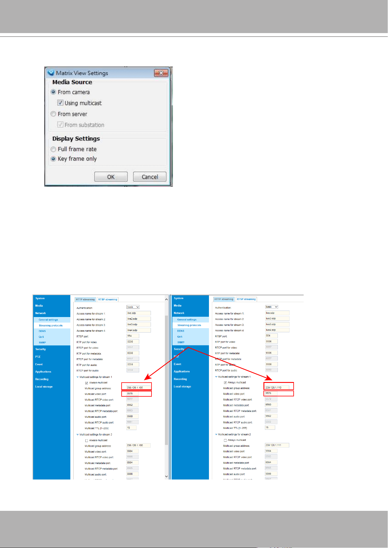
VIVOTEK - A Leading Provider of Multimedia Communication Solutions
180 - User's Manual
To congure Multicast video streaming for Matrix,
Using Multicast configuration help preserve cameras' system resources while streaming video to a
Matrix machine. Before applying the Multicast settings, the related network settings should be properly
congured on the individual network cameras.
1. Open the web console with the individual network cameras.
2. Enter the Conguration > Network > Streaming protocols window.
3. Change the Multicast settings for Stream 1 on each camera.
Note that it is very important to configure a
unique
Multiple Group address
for each camera.
Otherwise, images on the view cells will be overlapped, rendering the Matrix view useless. You can
also congure the
unique Multicast video port
into a unique number.
Display Settings
Note that if you change the adress, the same address for stream #2, #3, and #4 will change
accordingly.
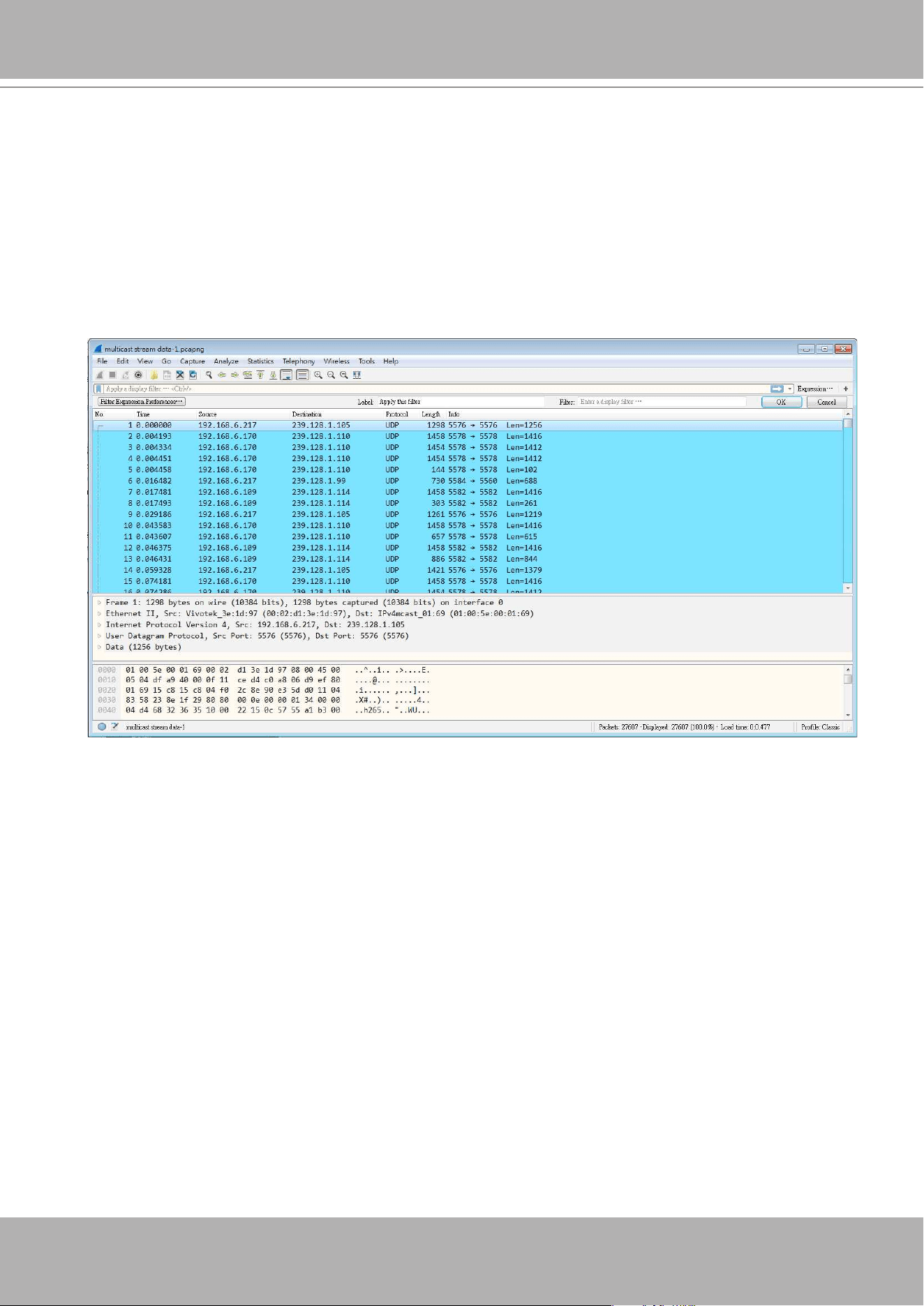
VIVOTEK - A Leading Provider of Multimedia Communication Solutions
User's Manual - 181
You can choose the display frame rate in the Matrix view as full frame rate or key frame only.
The 239.0.0.0/8 address range is assigned by RFC 2365 for private use within an organization.
From the RFC, packets destined to administratively scoped IPv4 multicast addresses do not cross
administratively defined organizational boundaries, and administratively scoped IPv4 multicast
addresses are locally assigned and do not have to be globally unique.
When nished with conguration, you can use the Wireshark utility to test the presence of multicast
packets.
If you select the
Always Multicast
checkbox on the conguration page, multicast trafc will always be
detected whether or not the Matrix settings have been synchronized or started between server and the
Matrix machine.
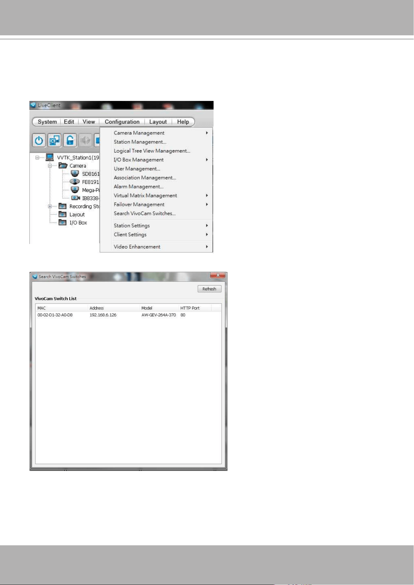
VIVOTEK - A Leading Provider of Multimedia Communication Solutions
182 - User's Manual
Search VIVOCam Switches
Use the serach managed switch function to locate and open a web console with the managed
switches. Double-click on the entry found to open a web console.
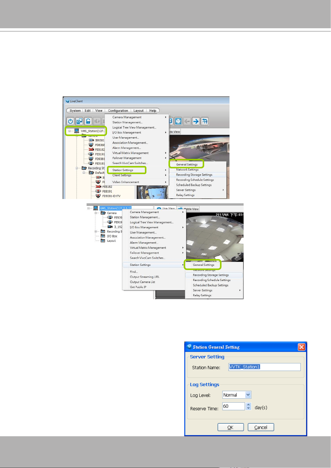
VIVOTEK - A Leading Provider of Multimedia Communication Solutions
User's Manual - 183
How to Congure the Station General Settings
Select the target station from the hierarchical management tree, then click
Configuration
> Station Settings > General Settings
on the menu bar (or
right-click
the station on the
hierarchical management tree and select
Station Settings > General Settings
). The
Station
General Settings
window will pop up.
Server Settings
In this section, you can modify the Station Name.
Log Settings
In this section, you can set up
Log Settings
for the station.
The VAST server allows user to search for the recorded
log through VAST Playback. For more information,
please refer to
How to Search Logs
on page 313.
Log level: Select
High
(only record high-level logs),
Normal
(record high-level and normal-level logs),
Low
(record all logs). For detailed information about log
levels, please refer to page 314.
Reserve Time: Enter the time interval that you want
to reserve the log record. The maximum value is 365
days.
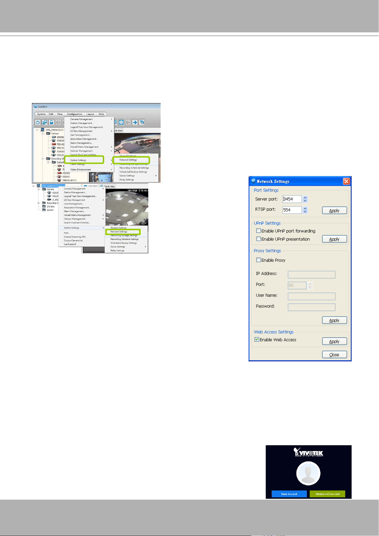
VIVOTEK - A Leading Provider of Multimedia Communication Solutions
184 - User's Manual
How to Congure Station Network Settings
Select the target station from the hierarchical management tree, then click
Configuration
> Station Settings > Network Settings
on the menu bar (or
right-click
the station on the
hierarchical management tree and select
Station Settings > Network Settings
). The
Network
Settings
window will pop up.
Port Settings
Server port: The default server port is set to 3454. If you change
the server port, please enter the new value while logging the
LiveClient next time.
RTSP port: The RTSP (Real-Time Streaming Protocol) controls the
delivery of streaming media. By default, the port number is set to
4543.
UPnP Settings
Enable UPnP port forwarding: For client to access the VAST Server
from the Internet, select this option to allow the server to open ports
on the router automatically so the video streams can be sent out
from a LAN. To utilize of this feature, make sure that your router
supports UPnP
TM
and it is activated.
Enable UPnP presentation: If you select this option, shortcuts to
VAST Server will be listed in My Network Places.
Proxy Settings
In this section, you can enable, modify, or cancel
Proxy Settings
for VAST Server if your network
devices are set up under a proxy.
Web Access Settings
User can access VAST LiveClient and Playback via Internet web browser
(
http://IP address:3454
).
F
or local host -->
http://127.0.0.1:3454. See page 153 for
Windows AD account information.
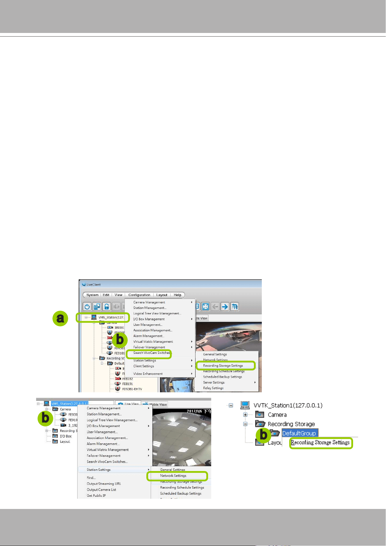
VIVOTEK - A Leading Provider of Multimedia Communication Solutions
User's Manual - 185
How to Edit Recording Groups
By default, all devices are assigned to the default recording group. You can manually remove
a device from the default recording group. However, only those devices which belong to a
recording group can produce recorded media les.
Another purpose of setting recording group is that you can divide all the managed devices into
several recording groups, and for each recording group, you can assign several hard-disks (with
recording paths) to store media data. The live media data will be stored in the first assigned
hard-disk initially, and when the available space of the first hard disk reaches the preset
reserved space limit, the media data will be stored in the second disk and so on. If the available
space of the last disk reaches the reserved space limit, the recorded les in the rst disk will be
overwritten with the new media data. This procedure is called "Cyclic Recording".
Recording Storage Settings
Please follow the steps below to set up recording groups for a station:
a. Select the target station from the hierarchical management tree.
b. Click
Conguration > Station Settings > Recording Storage Settings
on the menu bar (or
right-
click
the station on the hierarchical management tree and select
Station Settings > Recording
Storage Settings
). You can also
right-click DefaultGroup
under the station
and
click
Recording
Storage Settings
since all devices are assigned to the
Default Recording Group
by default.
c. The
Recording Storage Settings
window will pop up.
b
a
b
b
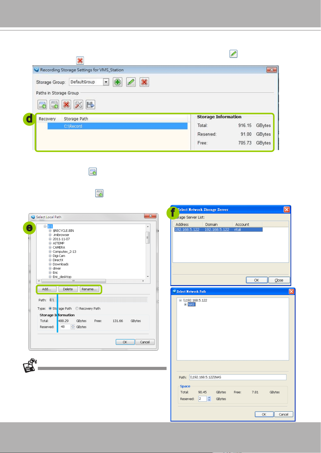
VIVOTEK - A Leading Provider of Multimedia Communication Solutions
186 - User's Manual
Default Storage Group Settings
The following example shows the default storage group settings. You can click
Rename
to modify the
group name or click
Delete
to remove the default settings.
d. The default recording path is
D:\Recording
. The total space and free space of the disk is shown on
the right for reference.
e. Add Local Path: Click
to add another recording path on your local computer. A Select Path dialog
will pop up as shown below. When all settings are complete, click
OK
to enable the settings, or click
Cancel
to discard the settings. The default reserved space is 10% of the disk volume.
f. Add Network Path: Click
to add a networked storage for recorded data. Please refer to page 214
for detailed information about how to add a new network storage server. Then double-click the
Path
to
assign a specic folder as a new recording path.
d
e
Click those buttons to modify the le
folder under D:\
f
Note that the reserved space is the comparatively
small amount of storage space saved for data
transaction during recording cycles. The reserved
space is not the storage space configured for
video recording.
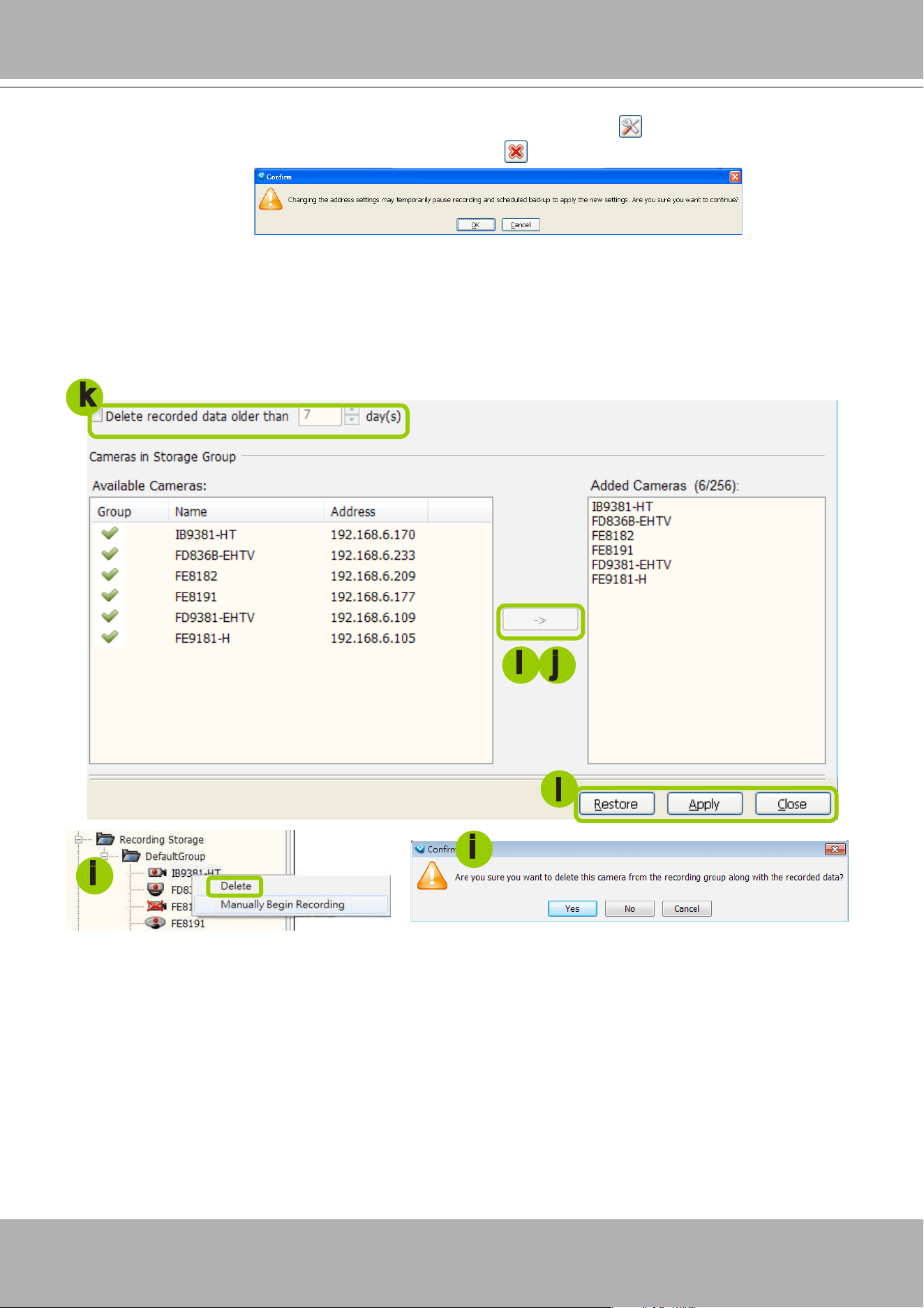
VIVOTEK - A Leading Provider of Multimedia Communication Solutions
User's Manual - 187
g. To modify the settings of a path, select the path from the list, then click
Change settings
to modify.
h. To delete a path, select the path from the list and click
Delete path
. A warning dialog box will pop
up as shown below.
i. By default, all devices are assigned to the
Default Recording Group
in the window on the right. You
can select device(s) from the list and click
<-
to delete device(s) (or
right-click
the device under
DefaultGroup tree to delete it). Note that a
Delete Camera
dialog box will pop up. Click
Yes
to delete
the device along with the recorded data; click
No
to delete the device but retain the recorded data;
click
Cancel
to cancel the delete action. Please note that only those designated devices can record
videos.
j. Click
->
to add devices to the
DefaultGroup
.
k. Delete recorded data older than the duration: If you only want to retain recorded data for a duration,
check this item and enter a number of day(s). In addition, since VAST Server will do "cyclic recording"
automatically, the oldest file will be overwritten by the latest one when the maximum capacity is
reached.
l. When completed, click
Apply
to confirm and save your settings. If you want to cancel all of your
editing, click
Restore
to return to the previous settings or click
close
to discard the settings.
i
i j
i
k
l
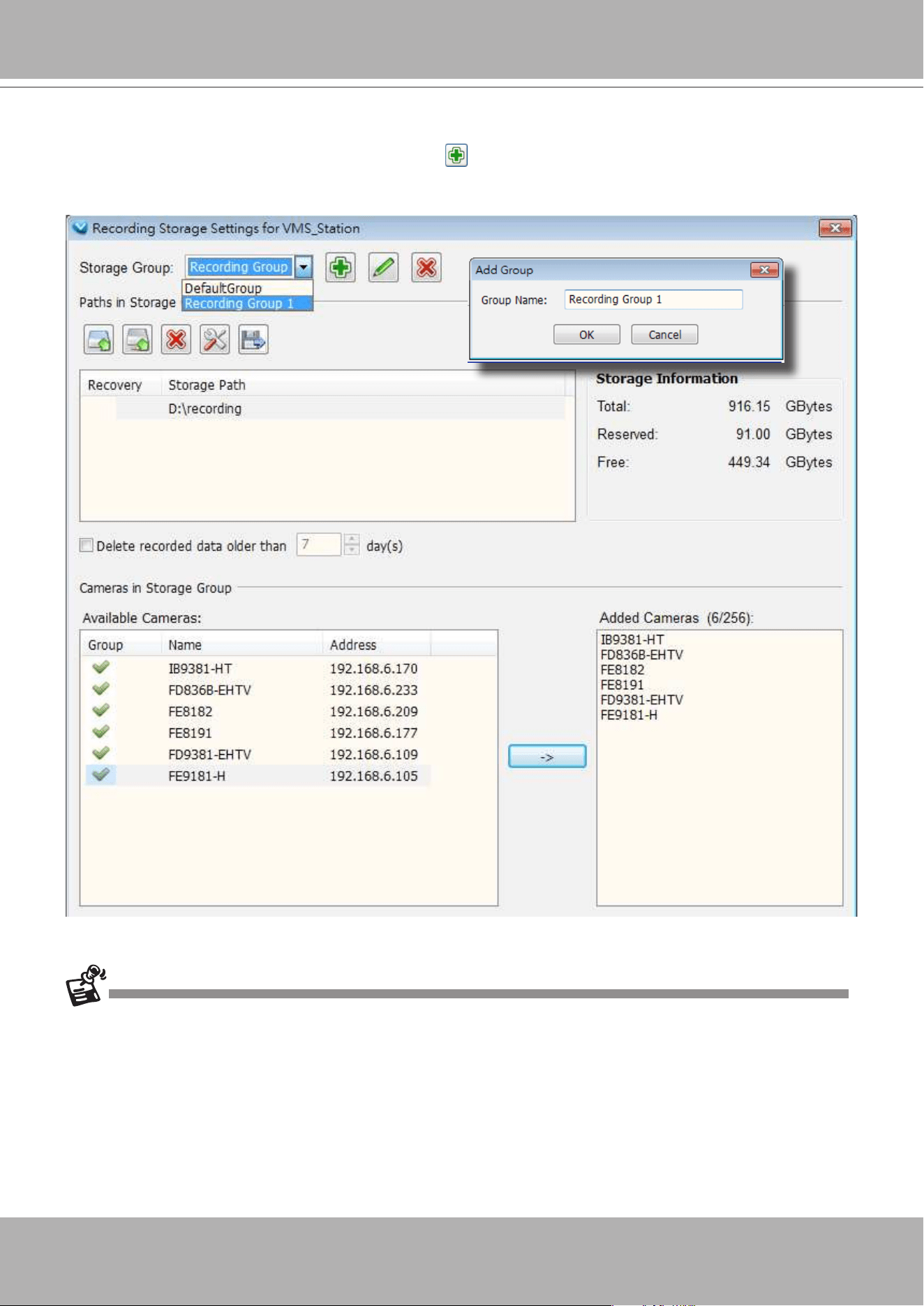
VIVOTEK - A Leading Provider of Multimedia Communication Solutions
188 - User's Manual
Add New Recording Group(s)
If you want to add a new recording group, click
Add
to give a name to the new recording group,
which will be displayed on the drop-down list.
The following is an example of recording group list.
Please refer to the following limits when you set up recording group(s):
The maximum number of devices in a recording group is 64-CH. Please refer to the system requirements of the
software.
One recording group can be assigned with several recording paths and perform cylic recording; while one
recording path should only be assigned to one recording group.
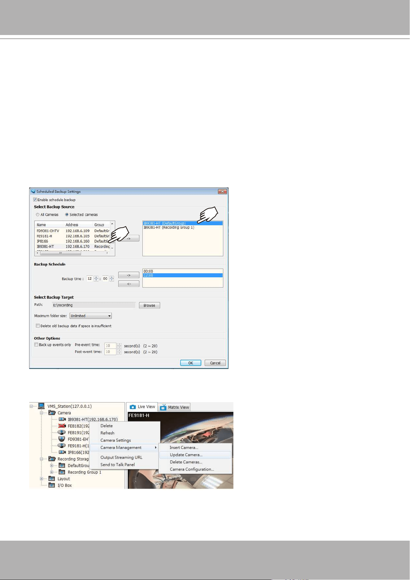
VIVOTEK - A Leading Provider of Multimedia Communication Solutions
User's Manual - 189
Multiple Stream Recording
Since software revision 1.12, a camera's stream can be recorded to different storage paths, e.g., the
server's internal storage and a Network Attached Storage. If hardware should fail (such as H.D.D. failure)
on the VAST server, video can still be retrieved from other storage devices. This feature provides fault-
tolerant redundancy for stream recording.
Functional Requirements:
1. Each camera can be configured into multiple Recording Storage Groups, and has individual
congurations in each storage group.
2. Separate recording schedules can be congured for each camera in different storage groups.
3. Schedule Backup Settings:
As shown below, when conguring a Schedule Backup, each camera in different storage groups will
be listed as individula entries. You can select to back up only one of the recording streams.
4. By default, every camera is recruited into the Default Storage Group. You can select a camera from
the device tree, right-click to select
Camera Management
>
Update camera
.
You can congure different video streams for different storage groups.
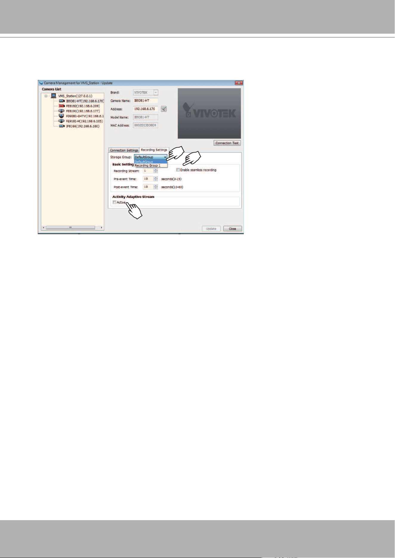
VIVOTEK - A Leading Provider of Multimedia Communication Solutions
190 - User's Manual
In here, you can congure the recording parameters for different storage groups. Note that you should
only enable
Seamless Recording
or
Active Adaptive Stream
in one of the storage group. Applying
these two functions on multiple streams can over-stress the camera.
5. When performing Instant Replay or Instant Playback, the system will poll the rst available storage
group only. If video is not available in the rst storage group, playback will fail.
Note that Multiple Stream Recording is not supported when access is made via a web console. From
a web console, playback displays the stream that last joined the recording storage group.
When the stream recording takes place on any of the camera's streams, the red indicator will light on
on the camera's view cell.
VIVOTEK - A Leading Provider of Multimedia Communication Solutions
User's Manual - 191
How to Edit Recording Schedules
After editing recording storage settings, you can begin to edit recording schedules for the
devices in a recording group. By default, all devices are assigned to the default recording
schedule (Please refer to the default time frame settings on page 195). Therefore, once you
insert a device to the station, the VAST Server will begin to record live video according to the
default recording schedule. You can also manually remove a device from the default recording
schedule. Please note that
you cannot assign recording schedules to those devices which
have been deleted from a recording group
.
The following is an illustration of a set of recording schedules, which are composed of several
time frames. Each time frame has its own time segments, period of time, repeat interval, and
recording mode. You can create different recording schedules with simple or complex time
frames based on your needs.
In addition, you can arrange the priority of each time frame according to its importance. The
recording schedule with the highest priority will be applied first. This capability is very useful
because you can specify a new time frame with the highest priority temporarily without modifying
the other time frames.
Features of the recording schedules:
Each device can be assigned to only one recording schedule.
Each recording schedule may contain many time frames.
Each time frame has its own repeat frequency and recording mode.
To save time editing recording schedules and time-frames, we also provide a useful
template
function to save your time on schedules/time-frames settings. That is, you can save a specied
schedule and download it as a template for future use or upload a well-arranged schedule
template designed by others.
Please note that after you save the recording settings in the server, the recording schedule will
begin automatically according to your settings.
Router
Time Frame a
Recording Schedule 1
Time Frame b
Time Frame n
Time Frame y
Recording Schedule N
Time Frame z
Devices in Recording Group
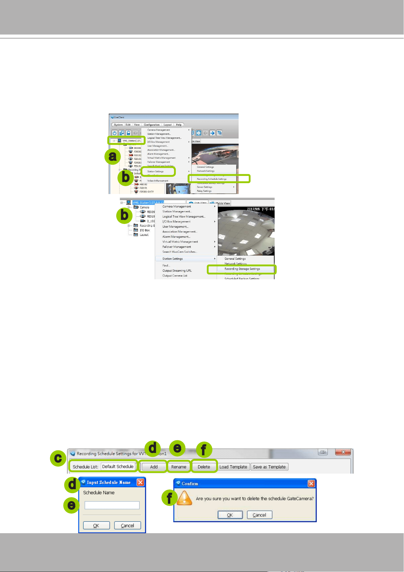
VIVOTEK - A Leading Provider of Multimedia Communication Solutions
192 - User's Manual
Edit Schedule List
Please follow the steps below to set up the recording schedules:
a. Select the target station from the hierarchical management tree.
b. Click
Conguration > Station Settings > Recording Schedule Settings
on the menu bar (or
right-
click
the station and select
Station Settings > Recording Schedule Settings
).
c. The
Recording Schedule Settings
window will pop up. By default, all cameras under the station are
assigned to
Default Schedule
,
Default Time Frame
, and
Default Camera List
.
Add Schedules
d. To add a new recording schedule, click
Add
to enter a name in the Schedule Name dialog box for the
new schedule. Click
OK
to conrm the settings or
Cancel
to discard the settings. The new recording
schedule will be displayed on the schedule drop-down list.
Rename Schedules
e. To rename an existing schedule, select the schedule from the schedule drop-down list and click
Rename
. A Schedule Name dialog will pop up for you to ll in a name for the new schedule. Click
OK
to conrm the settings or
Cancel
to discard the settings. The new recording schedule will be displayed
on the schedule drop-down list.
Delete Schedules
f. To delete an existing schedule, select the schedule from the schedule drop-down list and click
Delete
.
A Remove Schedule dialog box will pop up. Click
OK
to conrm or
Cancel
to discard the settings.
e
f
d
e
d
f
a
b
c
b
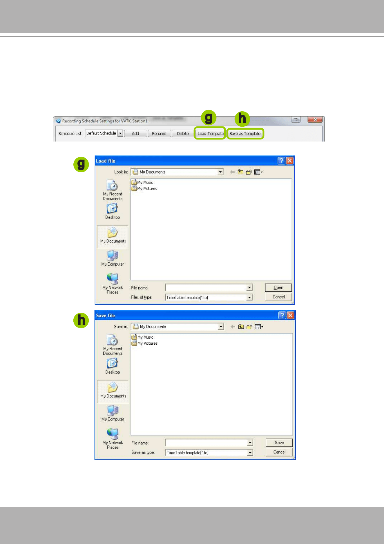
VIVOTEK - A Leading Provider of Multimedia Communication Solutions
User's Manual - 193
Load/Save Schedule Templates
g. If you have a schedule template with time frame settings, you can upload it to simplify the editing of
the schedule. Click
Load Template
, and a
Load File
dialog box will pop up. Select the template le
and click
Open
to load.
h. If you want to save a schedule as a template for future use, select the schedule from the schedule
drop-down list and click
Save as Template
. A
Save File
dialog box will pop up for you to save the
template le.
g
h
h
g
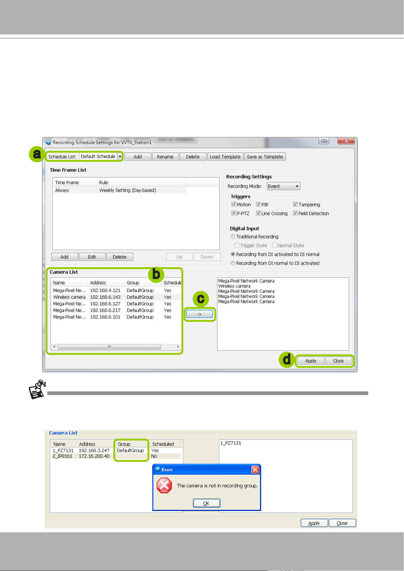
VIVOTEK - A Leading Provider of Multimedia Communication Solutions
194 - User's Manual
Edit Camera List
Please follow the steps below to assign a device to a recording schedule:
a. Select a recording schedule on the schedule drop-down list.
b. By default, all devices under the station are assigned to the
Default Schedule
.
c. Click
<<
to remove devices from the
Default Schedule
. Click
>>
to add devices to the
Default
Schedule
.
d. Click
Apply
to conrm or
Close
to discard the settings.
If you add a Network Device that does not belong to any Recording Group, a warning dialog will pop up as shown
below. For more information about how to set up Recording Group(s), please refer to Recording Group Settings on
page 185.
b
c
d
a
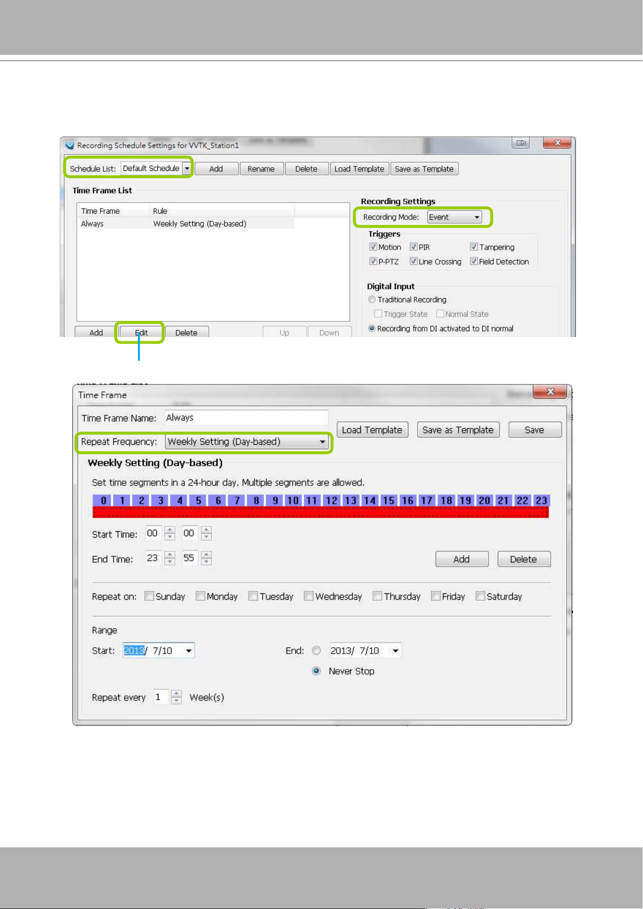
VIVOTEK - A Leading Provider of Multimedia Communication Solutions
User's Manual - 195
Edit Time Frame List
Default Time Frame: Weekly (Day-based), Mon.~Sun., 24-hour, continuous recording
Click
Edit
to open the Default Time Frame settings page as shown below.
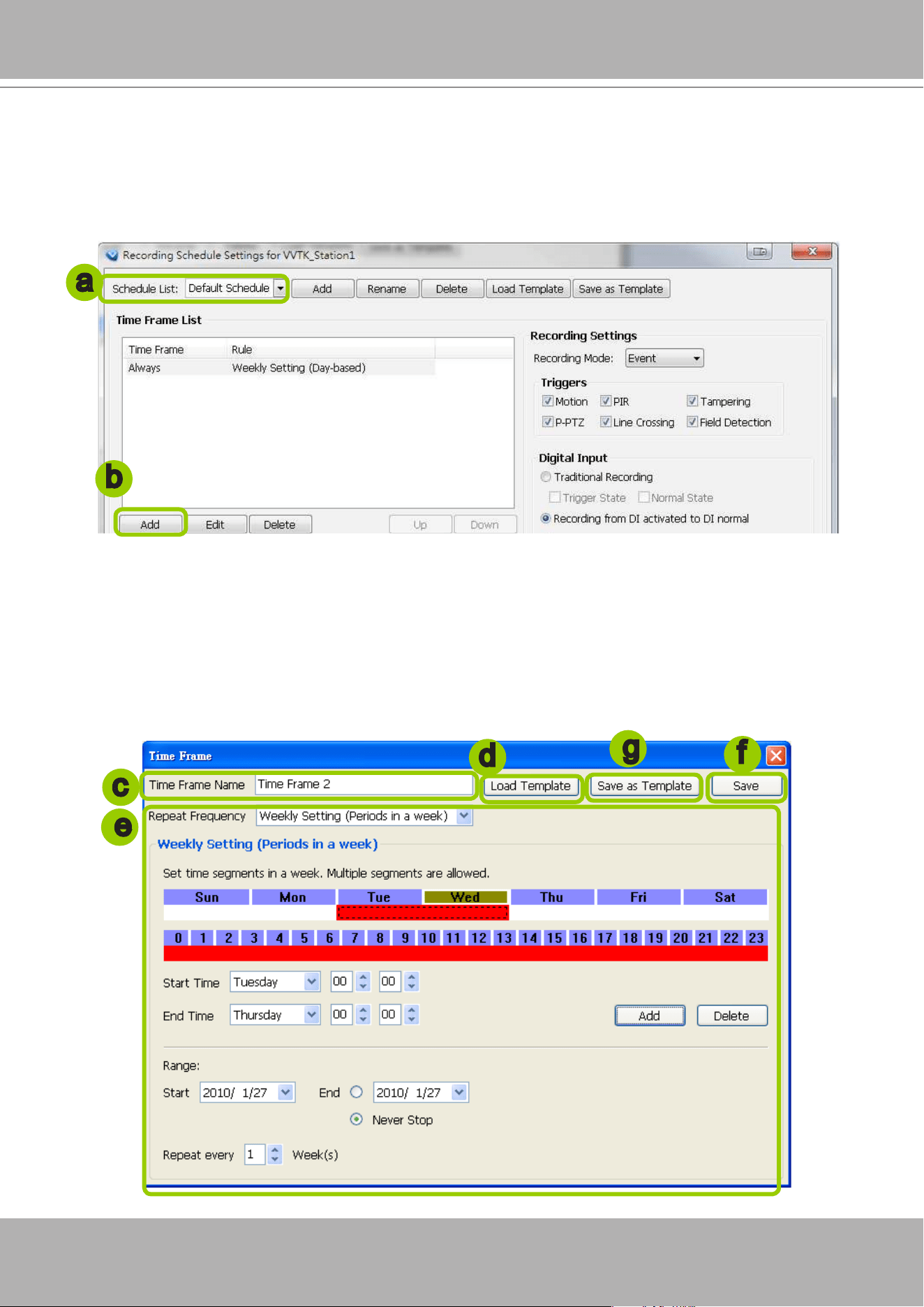
VIVOTEK - A Leading Provider of Multimedia Communication Solutions
196 - User's Manual
Add New Time Frames
Please follow the steps below to add new time frames to a schedule:
a. Select a recording schedule from the drop-down list.
b. Click
Add
to open the
Time Frame Settings
window.
c. Enter a name for the new time frame.
d. If you have a time-frame template, you can upload it to simplify the editing of the schedule. Click
Load
Template
and the
Load File
dialog box will pop up. Select the template le to load.
e. To edit the new time frame, select a
Repeat Frequency
from the drop-down list and edit the time
segments, applicable days, applicable period of time, and repeat time interval. For the
detailed settings
of each repeat frequency, please refer to
The Concept of Repeat Frequency
on page 199.
f. When completed, click
Save
to enable the settings.
g. If you want to save this time frame as a template for future use, click
Save as Template
. A
Save le
dialog will pop up for you to save the template.
a
b
c
d
f
g
e
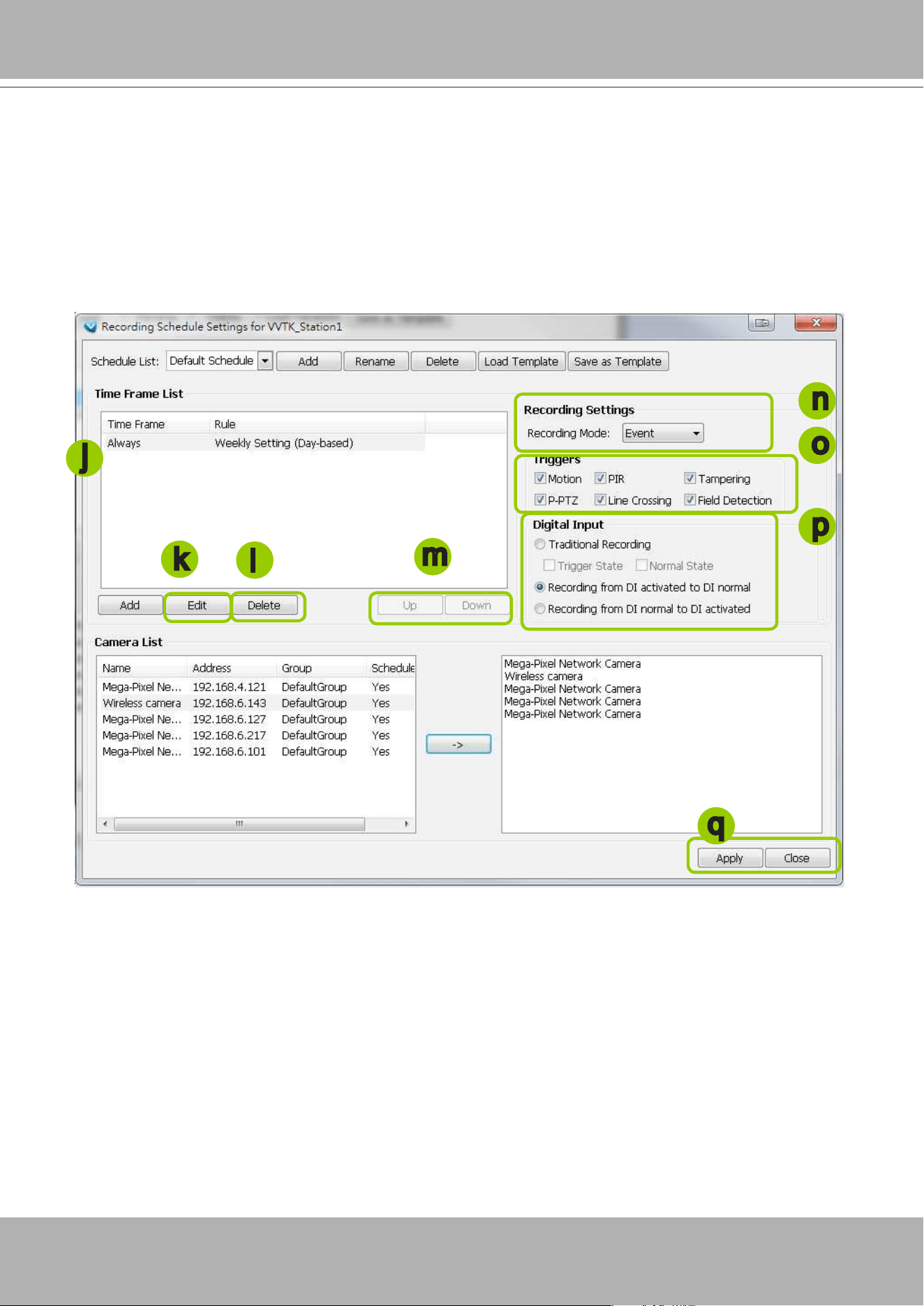
VIVOTEK - A Leading Provider of Multimedia Communication Solutions
User's Manual - 197
h. If you want to add additional time frames to the schedule, repeat the steps above.
i. Close the window when you nish the time frame settings.
j. Back to the Recording Schedule Settings window, the new time frame will be displayed on the Time
Frame List.
k. If you want to edit an existing time frame, select if from the Time Frame List and click
Edit
to set up.
l. If you want to delete an existing time frame, select if from the Time Frame List and click
Delete
.
m. If you want to change the priority of a time frame, select it from the Time Frame List and click
Up
or
Down
to shift its position. The time frame on the top of the list has the highest priority.
Recording Settings
n. Select one of the following Recording Modes for the time frame:
None
: No recording action.
Continuous
: 24-hours continuous recording. If you want to enable Activity Adaptive Streaming,
please refer to page 188 for detailed illutration.
Event
: The server will start to record only when an event is triggered. The recording time length
depends on the settings in Recording Storage Settings. The default time length is 20 seconds (10s
pre-event time plus 10s post-event time). Please refer to page 187 for more information. For more
information about event catagories, please refer to page 307 for detailed information.
o. Select Trigger Source(s): Motion Detection, Line Crossing, Field Detection, PIR, Tampering Detection,
and P-PTZ (Auto Tracking).
p. Digital Input: See next page for more information.
j
n
m
q
k
l
o
p
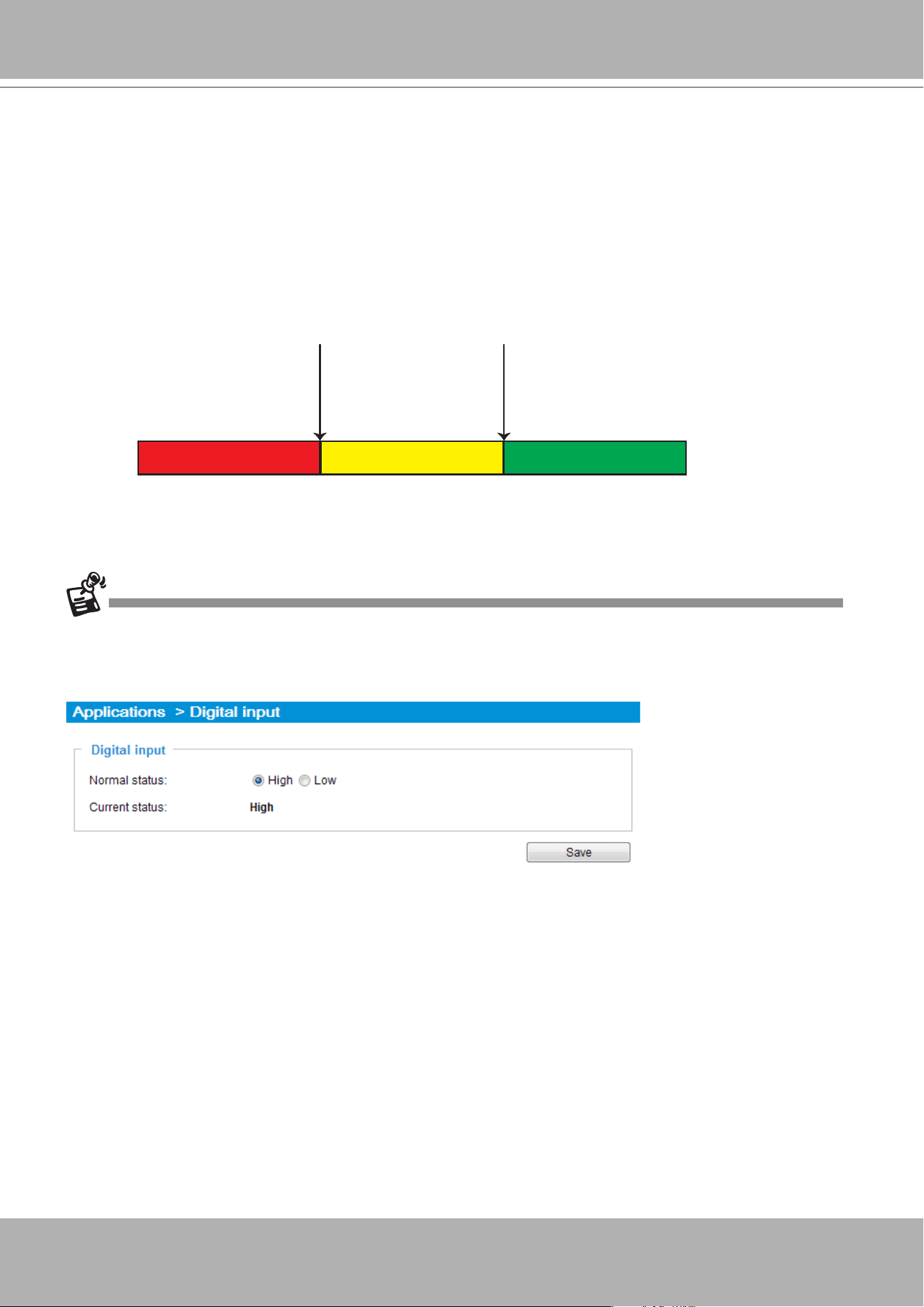
VIVOTEK - A Leading Provider of Multimedia Communication Solutions
198 - User's Manual
q. Click
Apply
to conrm the settings. Then close the window when you nish the recording schedule
settings.
The Digital Input signal triggers can be congured as follows:
1. Traditional Recording: can be triggered when the DI enters the Trigger State or the Normal
State. If thus configured, the recording task will end when the post-event recording time is
reached.
2. The recording starts when DI is triggered, and will end when the DI signal returns to Normal.
3. The recording starts when DI is Normal, and will end when the DI signal returns to Triggered.
4. The DI-triggered recordings also include the appended lengths of pre- and post-event recordings
(default is 10 seconds). Therefore, the length of DI-triggered recording is as follows:
When connected, a camera's Digital input signal is automatically detected as pulled-high or pulled-low.
Users should then designate the current state as Normal or Trigger. The conguration page is found in
Conguration
>
Application
>
Digital Input
on a web console.
DI triggered
Pre-recording Post-recording
DI returns to Normal state
An example for the conguration can be: the recording starts when a door is opened (DI triggered),
and the recording stops when the door is closed (DI returns to normal).
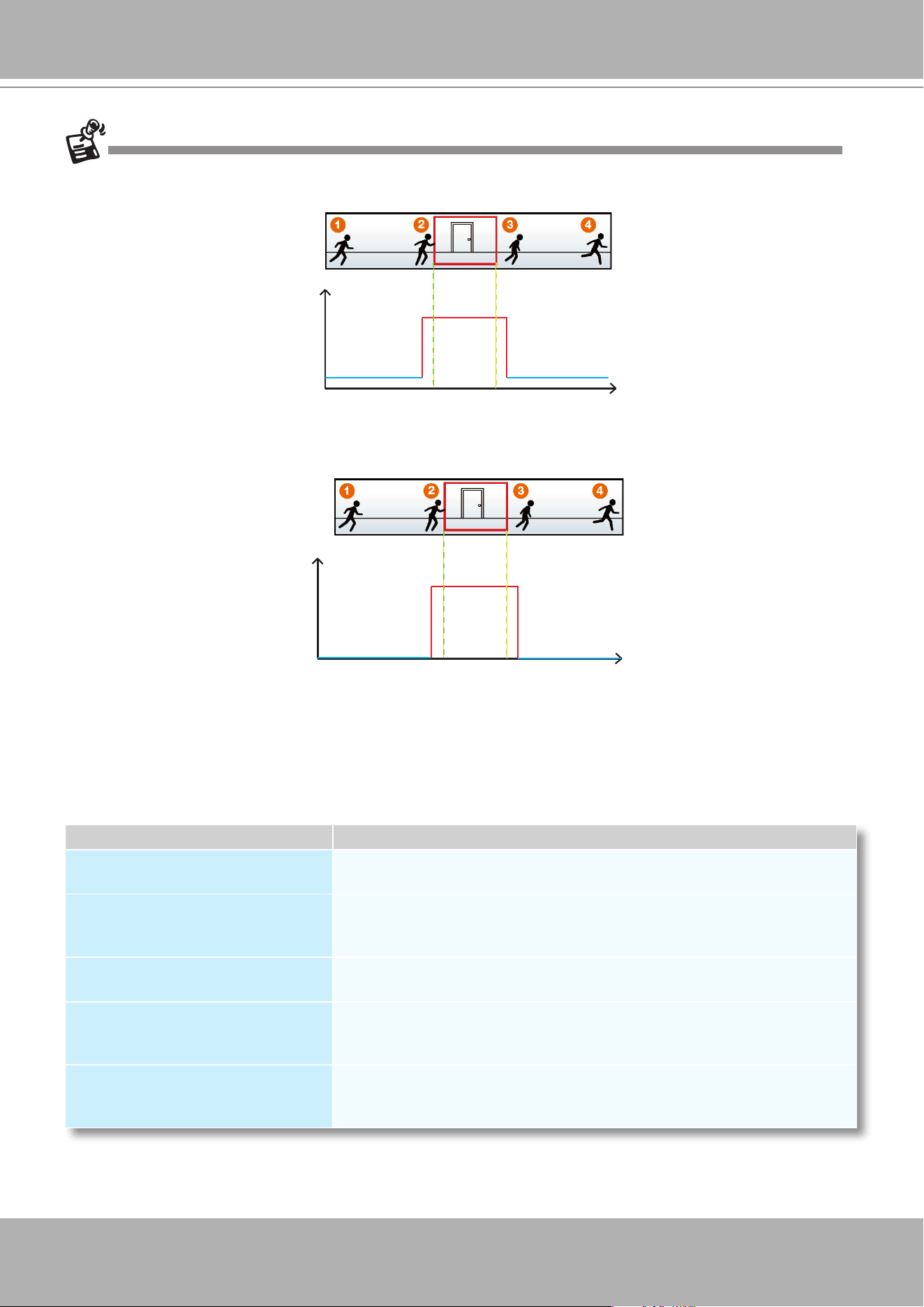
VIVOTEK - A Leading Provider of Multimedia Communication Solutions
User's Manual - 199
The following diagrams show the frame rate variation of two recording modes:
1. Continuous recording + Activity adaptive recording (helps save bandwidth and storage)
2. Event recording
The Concept of Repeat Frequency
VAST offers the following types of repeat frequency. The denition of each type is listed in the
following table:
Repeat Frequency Discription
Daily Setting
Specify arbitrary time segments within a day,
Repeat the segments every N days in the specied period of time.
Weekly Setting (Day-based)
(Default Time Frame)
Specify arbitrary time segments within a day,
Apply only on selected days of a week,
Repeat the segments every N weeks during the specied period of time.
Weekly Setting (Periods in a week)
Specify arbitrary time segments within a week,
Repeat the segments every N weeks during the specied period of time.
Monthly Setting (Day-based)
Specify arbitrary time segments within a day,
Apply only on selected days of a month,
Repeat the segments every N months during the specied period of time.
Yearly Setting (Day-based)
Specify arbitrary time segments within a day,
Apply only on selected days of a year,
Repeat the segments every N years during the specied period of time.
Time
Bandwidth
Continuous Recording
I frame ---> Full frame rate ---> I frame
Event Recording
Time
Bandwidth
No recording data ---> Full frame rate ---> No recording data
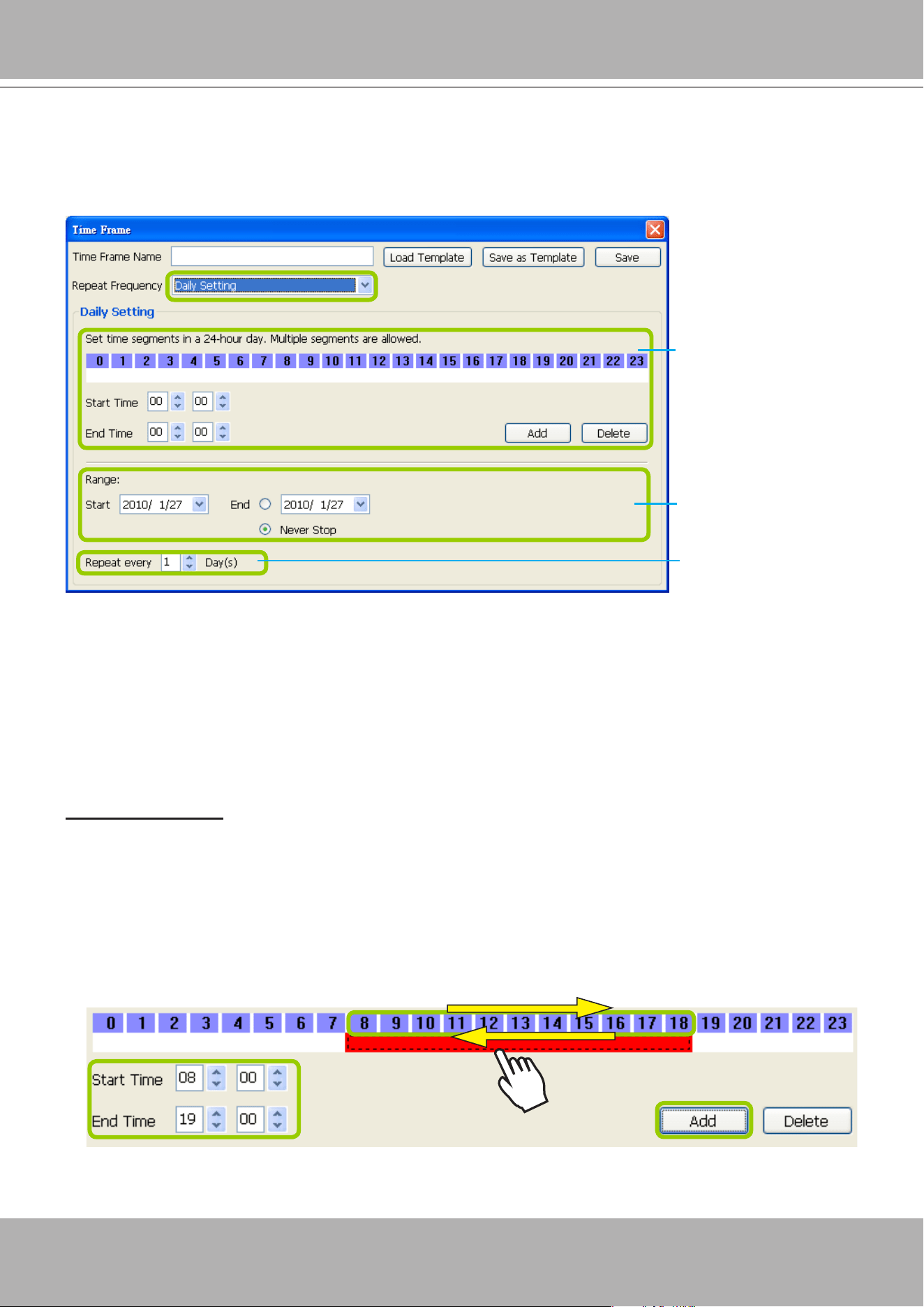
VIVOTEK - A Leading Provider of Multimedia Communication Solutions
200 - User's Manual
Repeat Frequency: Daily Setting
To set up daily repeat frequency, please congure the following items: Daily time segments, applicable
period of time, and repeat time interval.
Set up daily time segments
You can specify several time segments within a day. The numbers 0~23 on the
hourly timeline control
bar
(the purple rectangles) represent the 24 hours in a day.
There are two ways to define time segments: one is to use the computer mouse to manipulate the
timeline control bars; the other is to fill in the precise start and end time values in the corresponding
elds.
Add time segments: Choose either step 1 or step 2 to set up
1. Use the mouse to drag the timeline bars:
a.
Left-click
the
daily timeline control bar
(the purple rectangles) and drag the mouse.
b. The corresponding time segment will also appear in the Start Time and End Time elds. Click
Add
,
then the red timeline bars representing new time segments will appear as shown below. You can
drag multiple time segments within a day.
In the following illustration, the yellow arrows show the dragging direction of the mouse. You can
drag from left to right or the opposite.
Daily time segments
*You can drag the daily
timeline bar for more
than one time segment
per day.
Applicable period of
time
Repeat time interval
Daily timeline control bar
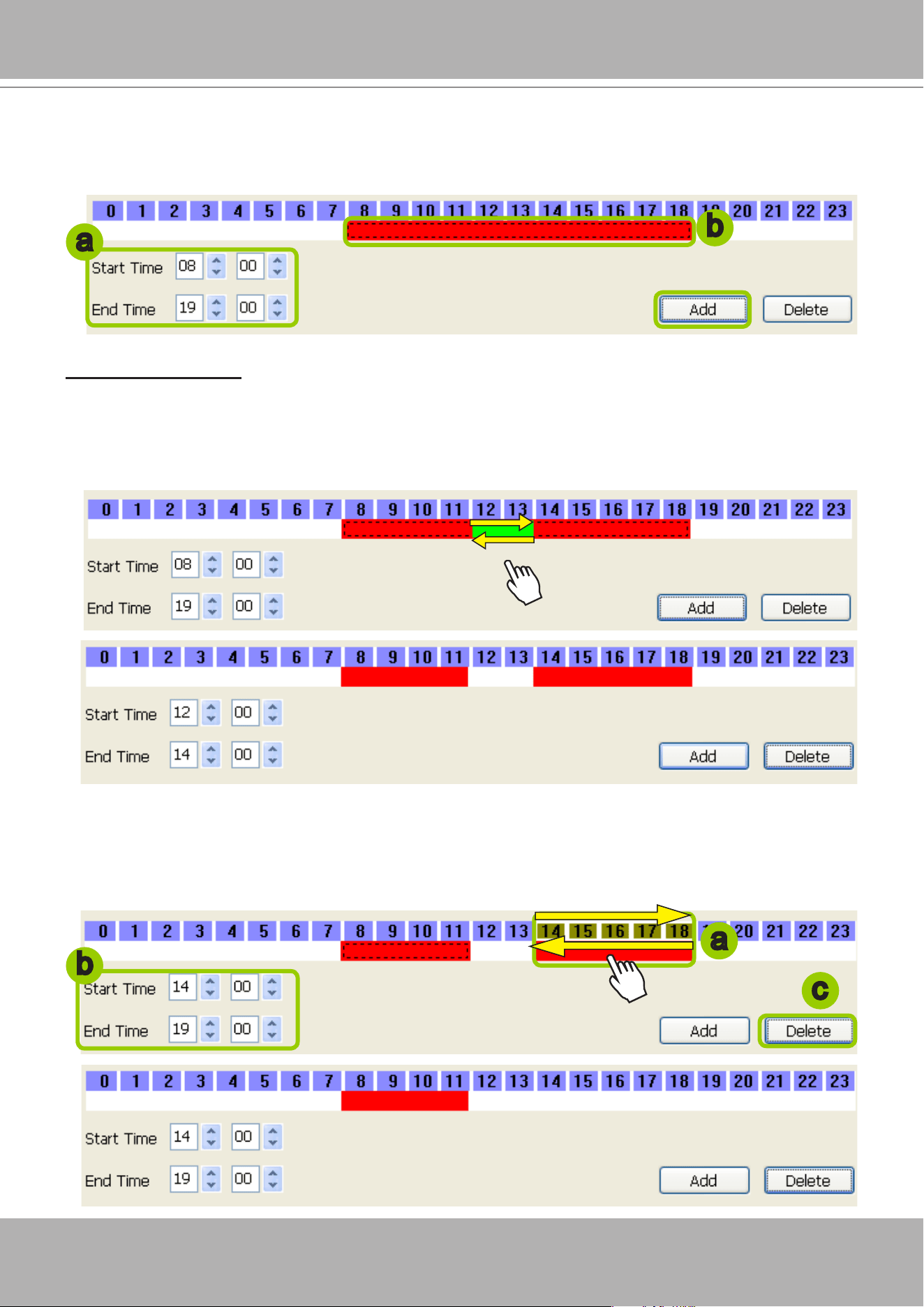
VIVOTEK - A Leading Provider of Multimedia Communication Solutions
User's Manual - 201
2. Fill in the precise Start Time and End Time:
a. Directly enter the value in the Start Time and End Time fields, then click
Add
.
b. The corresponding red timeline bar will automatically appear as shown below.
Delete time segments: Choose either step 1 or step 2 to set up
1. Use the mouse to erase the timeline bar:
Right-click
on an existing red timeline bar and drag the
mouse. A green timeline bar representing the deleted part of the time segment will erase the red bar as
shown below.
In the following illustration, the green arrows show the dragging direction of the mouse. You can drag it
from left to right or the opposite.
2. Use the delete button to remove the entire timeline bar:
a. Click an existing red timeline bar or
left-click
the
daily timeline control bar
(the purple rectangles)
and drag the mouse.
b. The corresponding time segment will appear in the Start Time and End Time fields.
c. Click
Delete
, and the selected timeline bar will disappear.
a
b
a
c
b
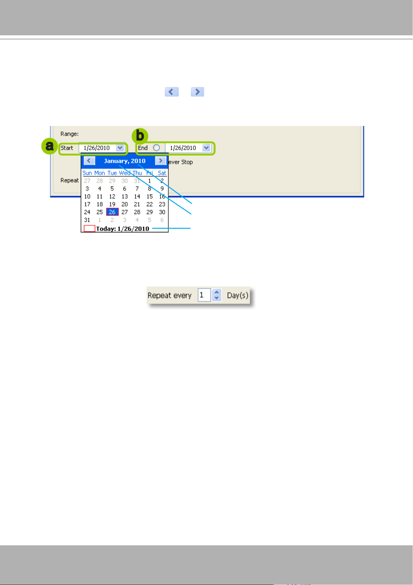
VIVOTEK - A Leading Provider of Multimedia Communication Solutions
202 - User's Manual
Set up applicable period of time
For repeat frequencies, you can set up the applicable date and period of time for the time frame.
a. Specify the start date and time in the
Start
eld. A calendar date selector will appear when you click
on the drop-down list of
date
. Click or to select the month, then pick a desired day in the
calendar.
b. Specify the end date and time in the
End
eld if you have an end time for applying this time frame. If
you do not have a terminating time for this time frame, select
Never Stop
.
Set up repeat time interval
The repeat time intervals is "every N day(s)" as shown below. Repeat every 1 day means the time frame
would apply for every day within the period of time.
Click to select a year
Click to select a month from the drop-down list
b
a
Click here to move the focus to the current date
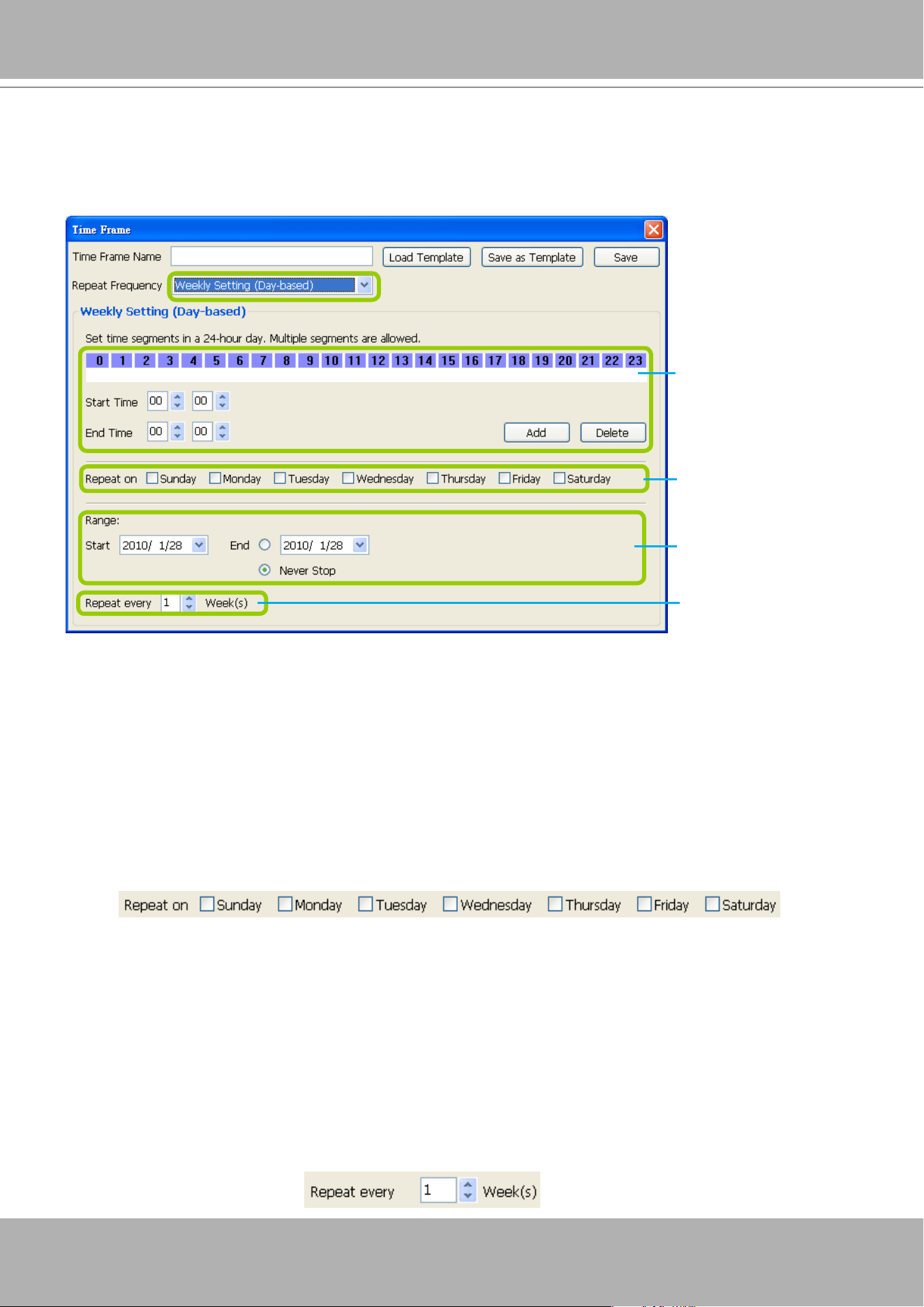
VIVOTEK - A Leading Provider of Multimedia Communication Solutions
User's Manual - 203
Repeat Frequency: Weekly Setting (Day-based)
To set up Weekly (Day-based) repeat frequency, please configure the following items: Daily time
segments, applicable days within a week, applicable period of time, and repeat time interval.
Set up daily time segments
Please refer to page 200 for detailed instructions.
Set up applicable days within a week
For repeat frequency--"Weekly (day based)", you can apply the time segments only on selected days of
the week.
Set up applicable period of time
Please refer to page 202 for detailed instructions.
Set up repeat time interval
The repeat time intervals is "every N week(s)" as shown below. Repeat every 1 week means the time
frame would apply for every week within the period of time.
Daily Time segments
*You can drag more
than one time segment
per day.
Applicable days
within a week
Applicable period of
time
Repeat time interval
Daily timeline control bar (24h)

VIVOTEK - A Leading Provider of Multimedia Communication Solutions
204 - User's Manual
Repeat Frequency: Weekly Setting (Periods in a week)
To set up Weekly (Periods in a week) repeat frequency, please configure the following items: Time
segments within a week, applicable period of time, and repeat time interval.
Set up time segments within a week
You can specify several time segments within a week. The
weekly timeline contol bar
represents the
7 days of a week, and the
daily timeline contol bar
represents the 24 hours in a day. The daily timeline
control bar is only valid when one of the days on the weekly timeline control bar has been selected.
There are two ways to set up time segments: one is to use the computer mouse to draw the timeline
control bars; the other is to ll in the precise start and end time value in the corresponding elds.
Add time segments: Choose either step 1 or step 2 to set up
1. Use the mouse to drag the timeline bars:
a. Click on a day on the
weekly timeline control bar
. The selected bar will turn green.
b.
Left-click
the
daily timeline control bar
and drag the mouse.
c. The corresponding time segment will also appear in the Start Time and End Time elds. Click
Add
,
then the red timeline bars representing new time segments will appear as shown below. You can
drag multiple time segments within a day and a week.
In the following illustration, the yellow arrows show the dragging direction of the mouse. You can
drag from left to right or the opposite.
Time segments within
a week
*You can drag more
than one time segment
per week.
Applicable period of
time
Repeat time interval
Weekly timeline control bar
Daily timeline control bar (24hr)
a
b
c
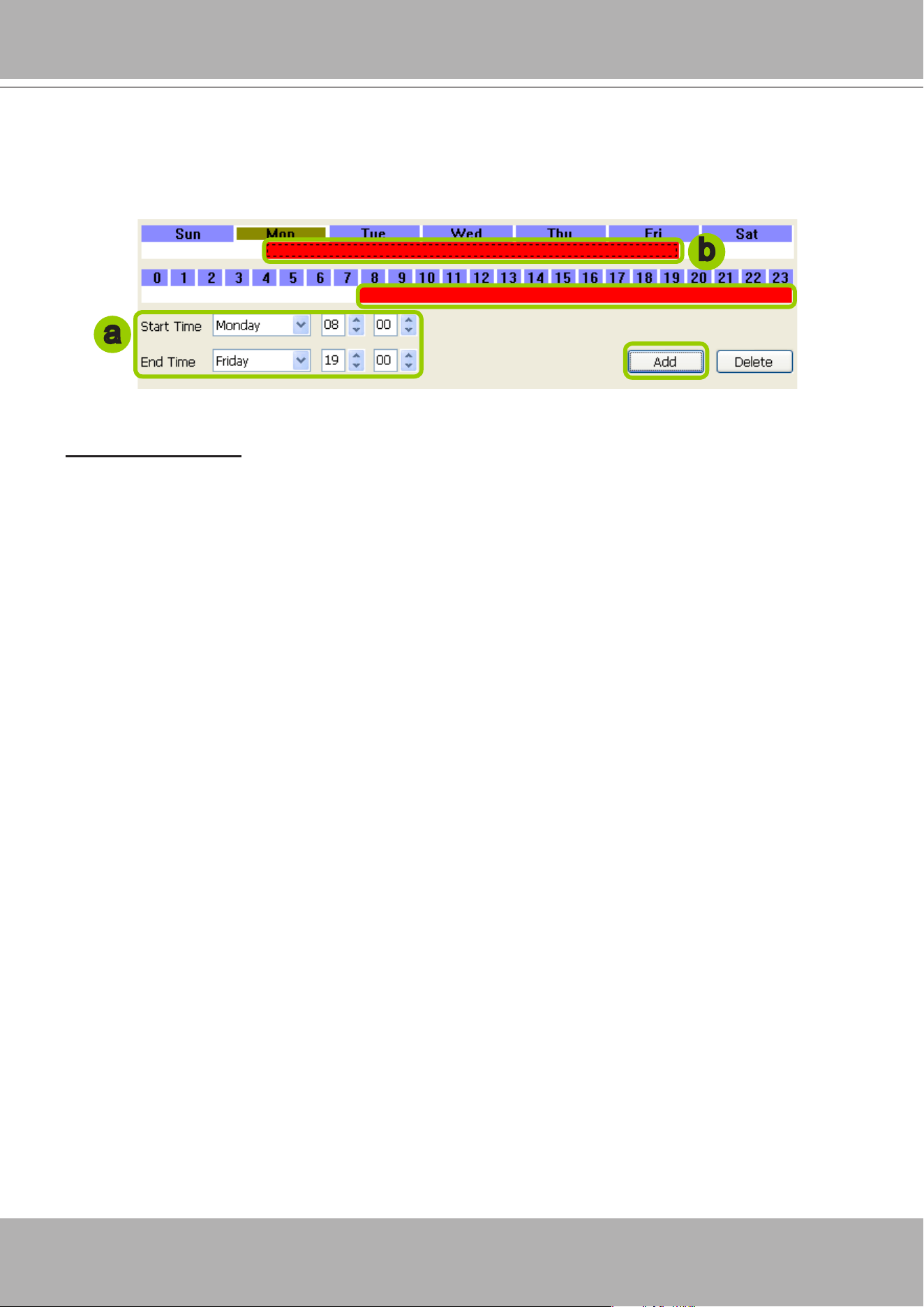
VIVOTEK - A Leading Provider of Multimedia Communication Solutions
User's Manual - 205
2. Fill in a precise Start Time and End Time:
a. Directly select a day and enter the value in the Start Time and End Time fields, then click
Add
.
b. The corresponding red timeline bars will automatically appear as shown below.
The following is an example of an extended time segment from Mon. 8:00 to Fri. 19:00.
Delete time segments:
Please refer to page 201 for detailed instructions.
Set up applicable period of time
Please refer to page 202 for detailed instructions.
Set up repeat time interval
Please refer to page 203 for detailed instructions.
a
b
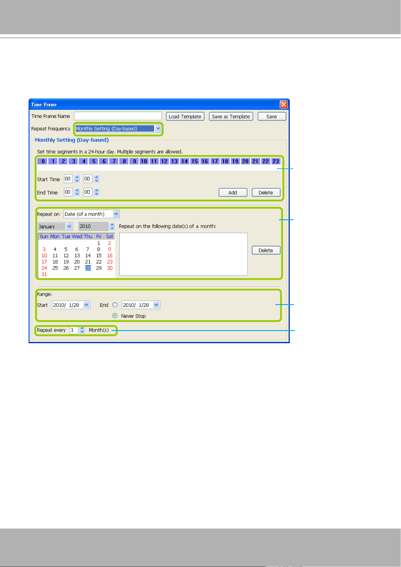
VIVOTEK - A Leading Provider of Multimedia Communication Solutions
206 - User's Manual
Repeat Frequency: Monthly Setting (Day-based)
To set up Monthly (Day-based) repeat frequency, please configure the following items: Daily time
segments, applicable date(s) of a month/ day(s) of a week, applicable period of time, and repeat time
interval.
Set up daily time segments
Please refer to page 200 for detailed instructions.
Set up applicable date(s) of a month/ day(s) of a week
For repeat frequency--"monthly (day-based)", you can apply the time segments only on selected days of
a month. There are two types of repeat frequencies: Date(s) of a month and Day(s) of a week.
Daily time segments
*You can drag more
than one time segment
per day.
Timeline control bar (24hr)
Applicable date(s) of
a month/ day(s) of a
week
Applicable period of
time
Repeat time interval
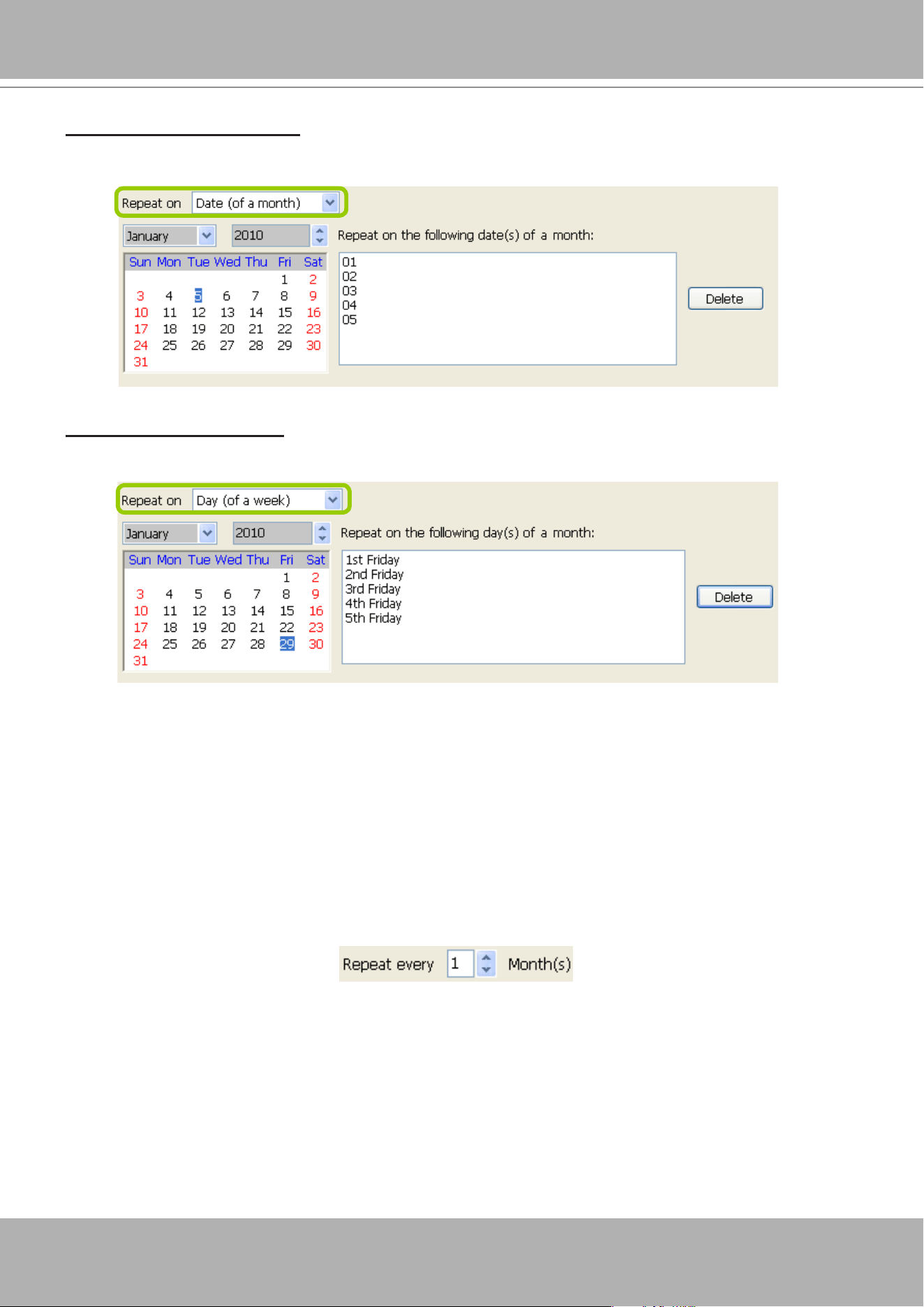
VIVOTEK - A Leading Provider of Multimedia Communication Solutions
User's Manual - 207
Repeat by date(s) of a month:
Select date(s) from the calendar, and it will be displayed on the right blank as shown below.
The following example refers to the 1
st
~
5
th
day of a month.
Repeat by day(s) of a week:
Select day(s) from the calendar, and it will be displayed on the right blank as shown below.
The following example refers to the 1
st
~ 5
th
Friday of a month.
Set up applicable period of time
Please refer to page 202 for detailed instructions.
Set up repeat time interval
The repeat time intervals is "every N month(s)" as shown below. Repeat every 1 month means the time
frame would apply for every month within the period of time.
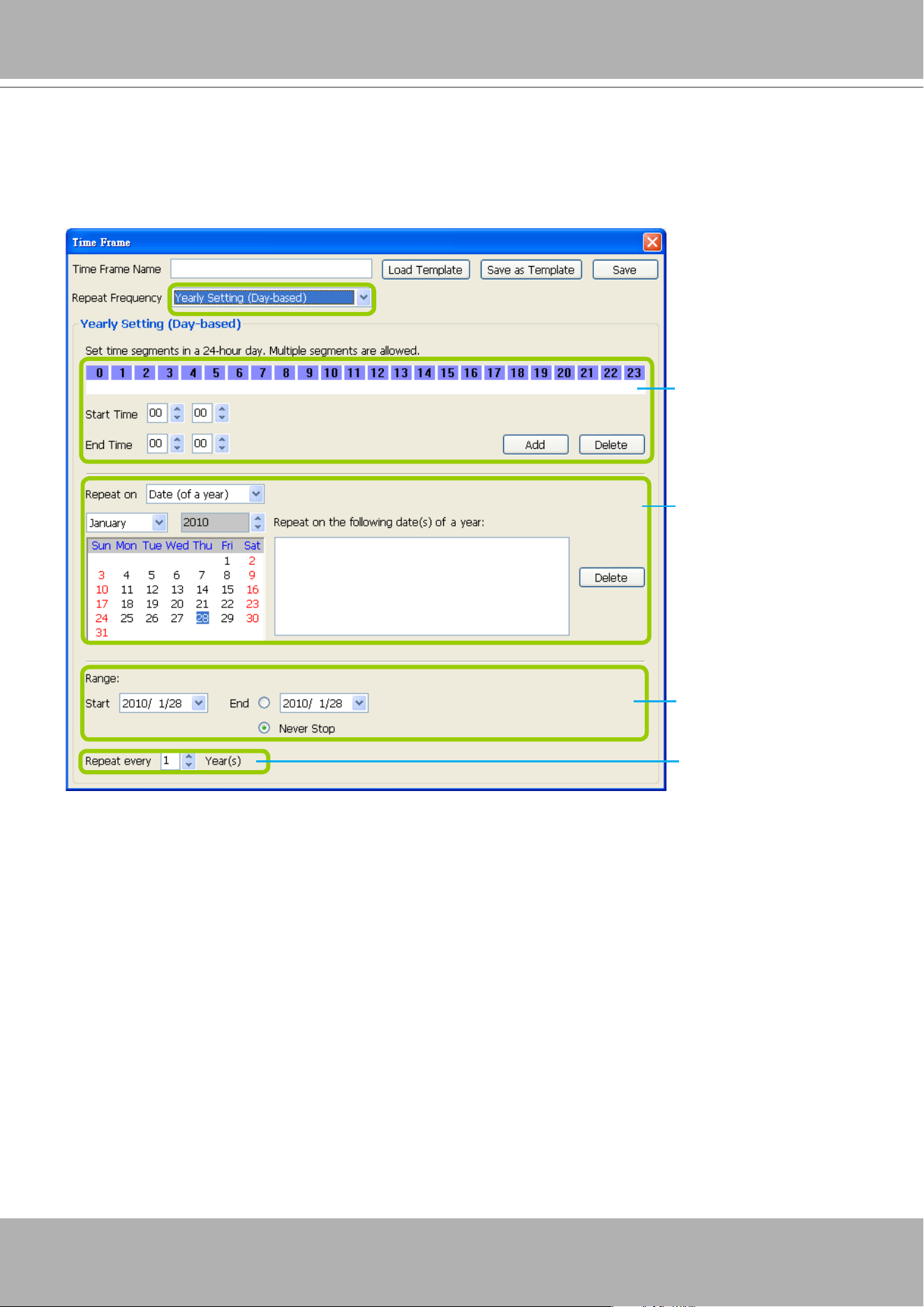
VIVOTEK - A Leading Provider of Multimedia Communication Solutions
208 - User's Manual
Repeat Frequency: Yearly Setting (Day-based)
To set up Yearly (Day-based) repeat frequency, please configure the following items: Daily time
segments, applicable date(s) of a year/ day(s) of a week, applicable period of time, and repeat time
interval.
Set up daily time segments
Please refer to page 200 for detailed instructions.
Set up applicable date(s) of a year/ day(s) of a week
For repeat frequency--"yearly (day-based)", you can apply the time segments only on selected days of a
year. There are two types of repeat frequencies: Date(s) of a year and Day(s) of a week.
Daily time segments
*You can drag more
than one time segment
per day.
Timeline control bar (24hr)
Applicable date(s)
of a year/ day(s) of a
week
Applicable period of
time
Repeat time interval
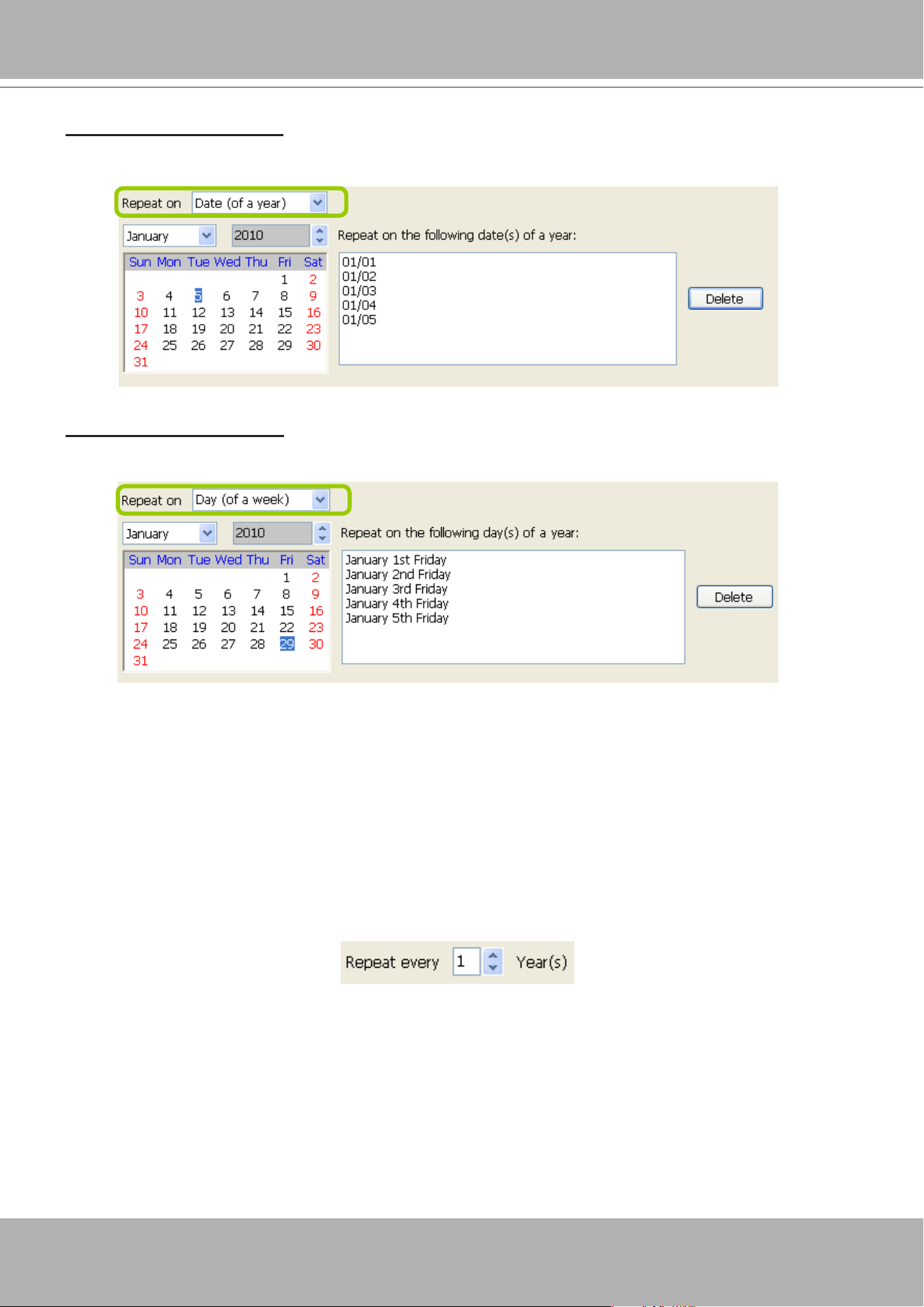
VIVOTEK - A Leading Provider of Multimedia Communication Solutions
User's Manual - 209
Repeat by date(s) of a year:
Select date(s) from the calendar, and it will be displayed on the right blank as shown below.
The following example refers to the 1
st
~
5
th
day of a year.
Repeat by day(s) of a week:
Select day(s) from the calendar, and it will be displayed on the right blank as shown below.
The following example refers to the January 1
st
~ 5
th
Friday of a year.
Set up applicable period of time
Please refer to page 202 for detailed instructions.
Set up repeat time interval
The repeat time intervals is "every N year(s)" as shown below. Repeat every 1 year means the time
frame would apply for every year within the period of time.
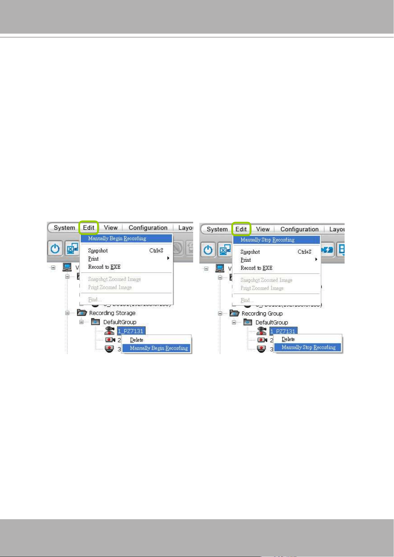
VIVOTEK - A Leading Provider of Multimedia Communication Solutions
210 - User's Manual
How to Manually Begin /Stop Recording
By default, all devices are assigned to the default recording storage and default recording
schedule. Therefore, once you insert a device onto the station, the VAST Server will begin
to record live video according to the default recording schedule. Please refer to
How to Edit
Recording Schedules
on page 191.
However, if you have changed the default schedule, you can manually click
Manually Begin
Recording
to enable a device without setting up a recording schedule. Please follow the
instructions below to manually begin recording.
Select the device from the hierarchical management tree under Default Group, then click
Edit
> Manually Begin Recording
on the menu bar (or
right-click
the device and select
Manually
Begin Recording
). The string on the menu bar will turn into
Manually Stop Recording
as
shown below and the VAST Server will start to record video from the target camera. Please
note that its priority will be higher than the recording schedule, so it will continue unless you
click
Manually Stop Recording.
After you click
Manually Stop Recording
, the device will then
follow the preset recording schedule.
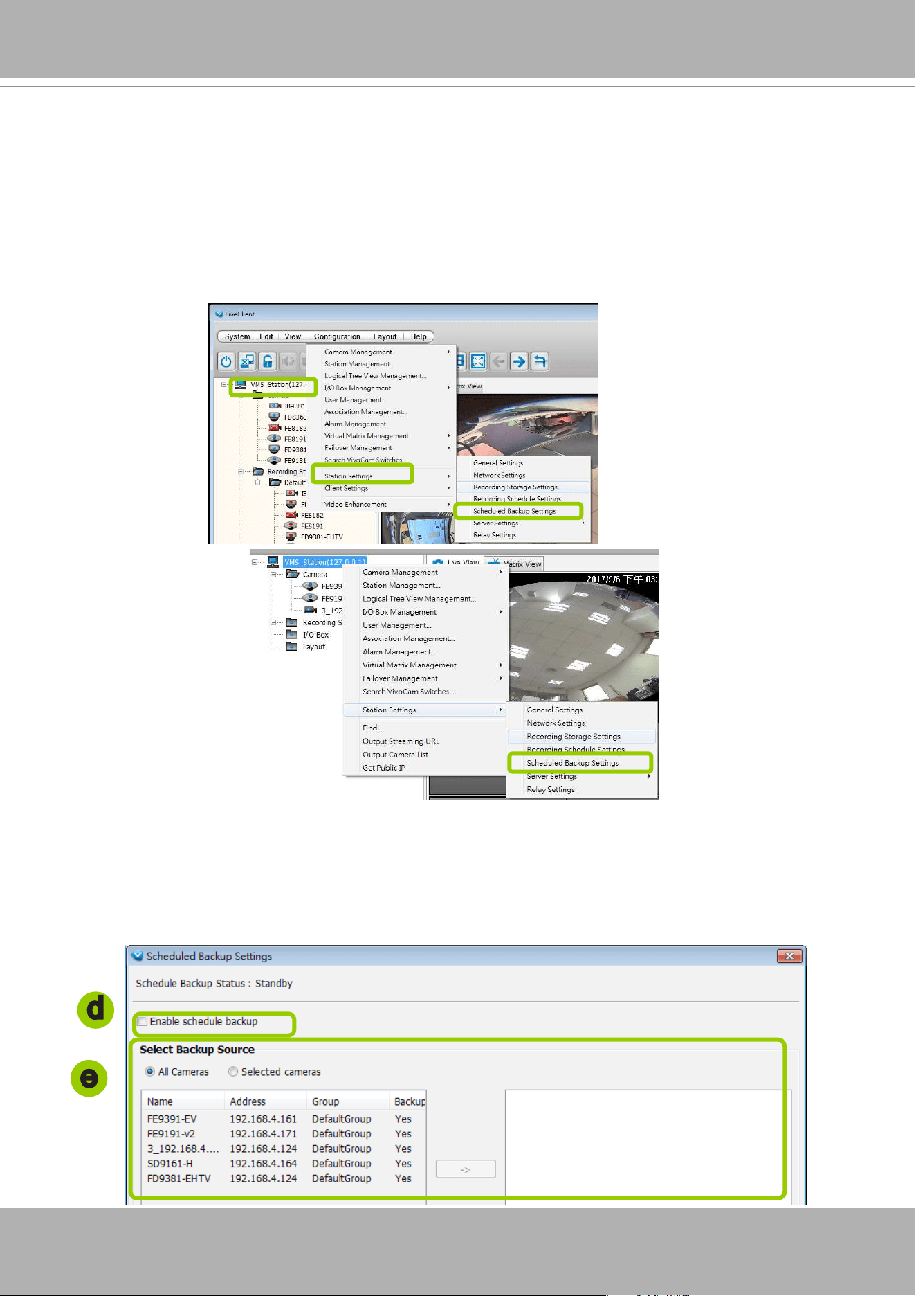
VIVOTEK - A Leading Provider of Multimedia Communication Solutions
User's Manual - 211
How to Edit Scheduled Backup Settings
VAST LiveClient supports scheduled backup which allows the user to back up the recorded data
to another disk.
Please follow the steps below to enable scheduled backup settings:
a. Select the target station from the hierarchical management tree.
b. Click
Conguration > Station Settings > Scheduled Backup Settings
on the menu bar (or
right-
click
the station and select
Station Settings > Scheduled Backup Settings
).
c. The
Scheduled backup settings
window displays.
Select Backup Source
d. Select the Enable scheduled backup checkbox.
e. Select the data source you want to backup. If you check
Selected cameras
, you can click
>>
or
<<
to
choose the data source that you want to backup.
d
e
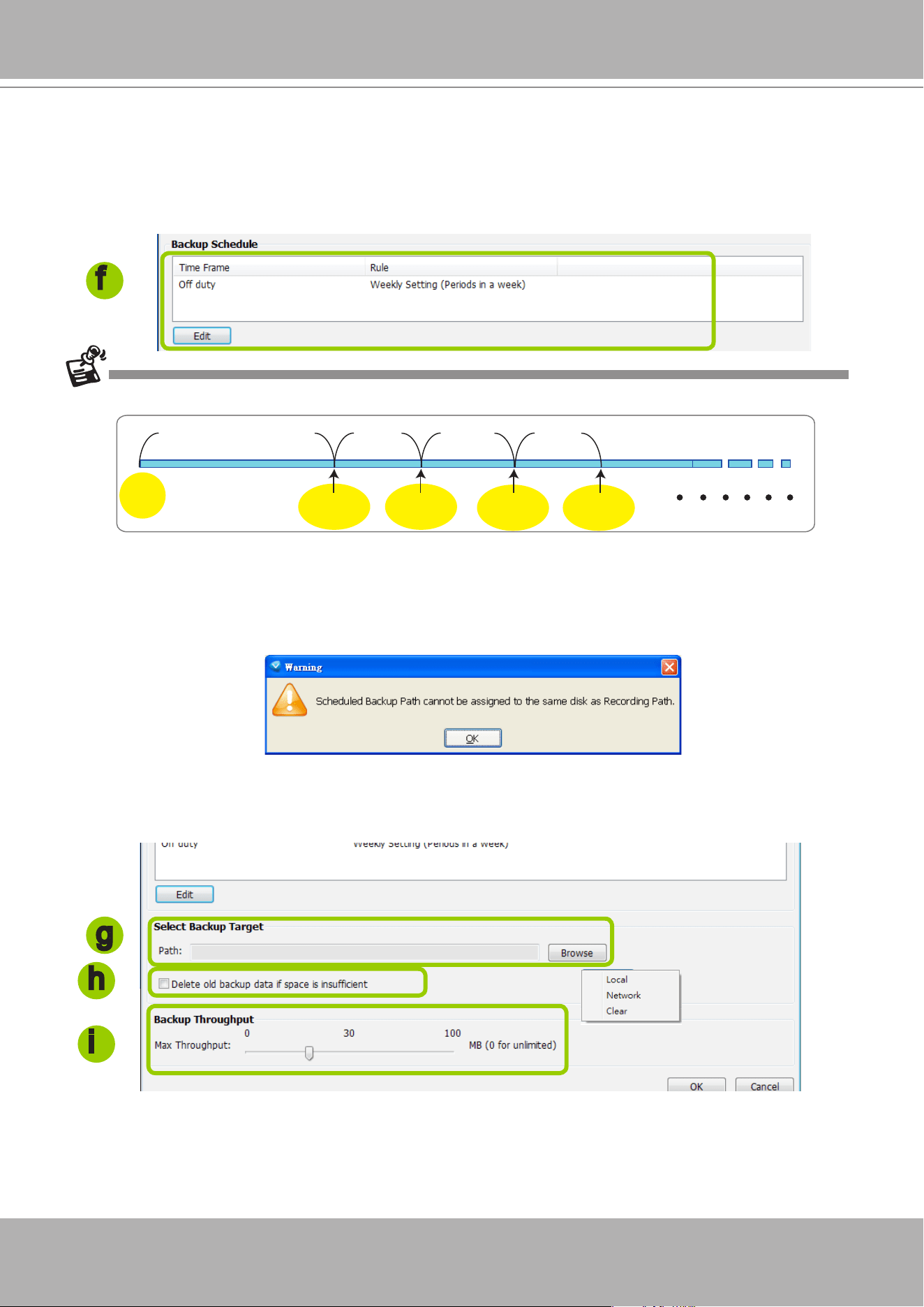
VIVOTEK - A Leading Provider of Multimedia Communication Solutions
212 - User's Manual
Setup Backup Schedule
f. Click the Edit button to enter the conguration screen. Please note that the backup time interval must
not be shorter than 1 hour. For example, 23:40 and 00:15 are not allowed to exist simultaneously.
In the following example, the server will backup the recorded data at 12:00 PM and 23:00 PM everyday
once you save the settings.
The following diagram shows the backup schedule and backup data:
Select Backup Target
g. Click
Browse...
to select a path (local path or network storage) to store the backup data. Please
note that the disk for backup data should be different from the original recording path, or a warning
message will pop up as shown below. For more information about how to set up recording path, please
refer to page 186.
h. Select
Delete old backups if space is insufcient
if you want to do cylic backup due to the limited
size of the hard disk.
i. Select the backup speed. The speed range start from 0 to 100MB/s. "0" stands for no limitation. If
bandwidth or system resource is of the concern, you can tune down the backup speed.
g
h
i
Server
start
12:00
2010/01/24
23:00
2010/01/24
12:00
2010/01/25
23:00
2010/01/25
2nd backup
data
1st backup
data
3rd backup
data
4nd backup
data
f
The backup destination folder should look like this "2016-07-06_164500 > DISC_001." A scheduled
backup error log will be available for users to examine the backup history.
Since the scheduled backup is a le-based process, if the backup involves an unnished video le
(currently being recorded), the backup process will skip the le.
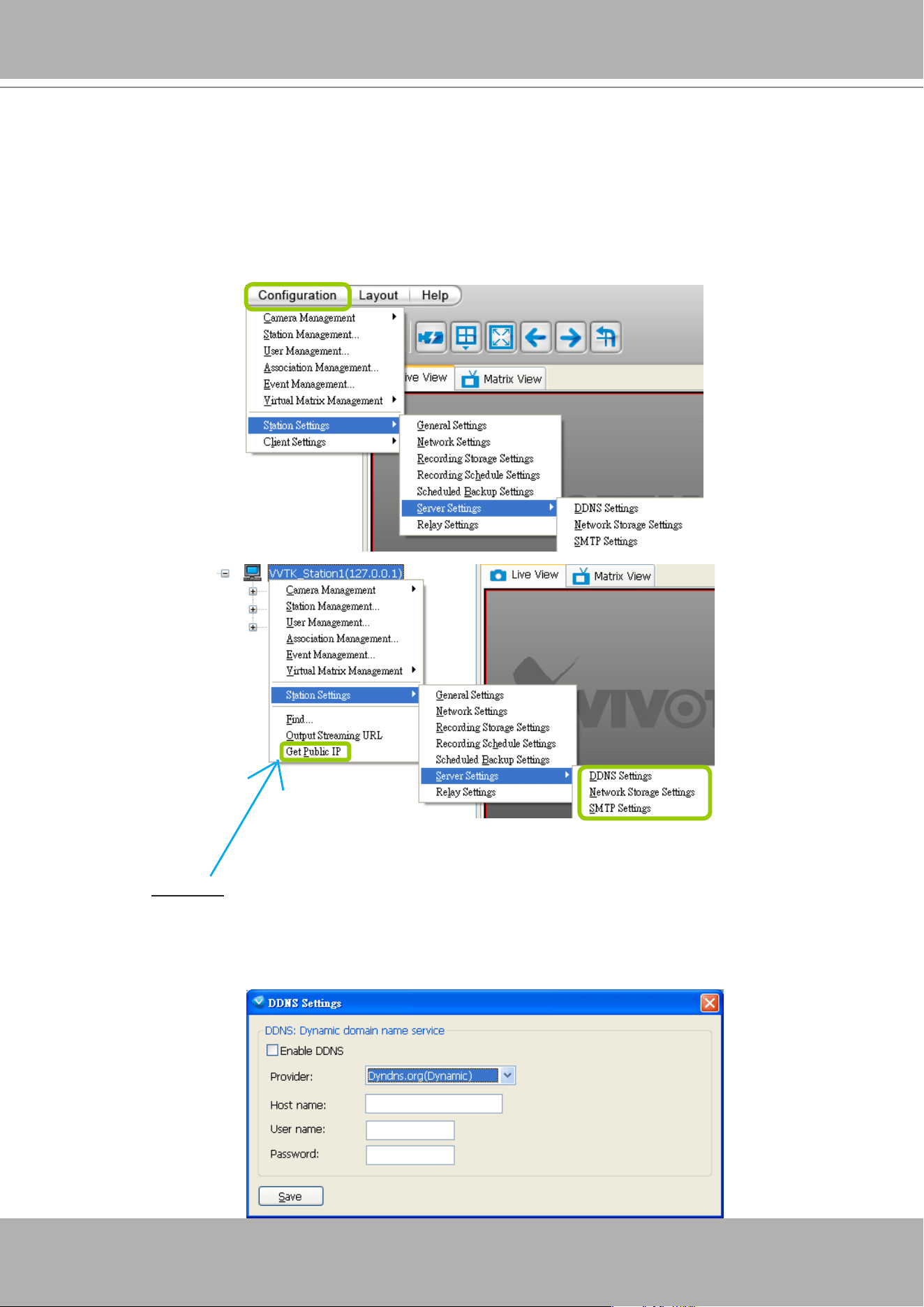
VIVOTEK - A Leading Provider of Multimedia Communication Solutions
User's Manual - 213
How to Congure Station Server Settings
VAST LiveClient supports Server Settings including DDNS Settings, Network Storage Settings,
and SMTP Settings.
Select the station from the hierarchical management tree and click
Configuration > Station
Settings > Server Settings
to open the page (or
right-click
the station and select
Station
Settings > Server Settings
).
DDNS Settings
Since the public IP of VAST Server may be a dynamic IP address, DDNS service will give it a
xed domain name.
Select a DDNS provider from the provider drop-down list. VIVOTEK offers 2bthere.net (Safe100.
net), a free dynamic domain name service, to VIVOTEK customers. Please refer to the user's
manual of VIVOTEK's network camera for detailed DDNS settings.
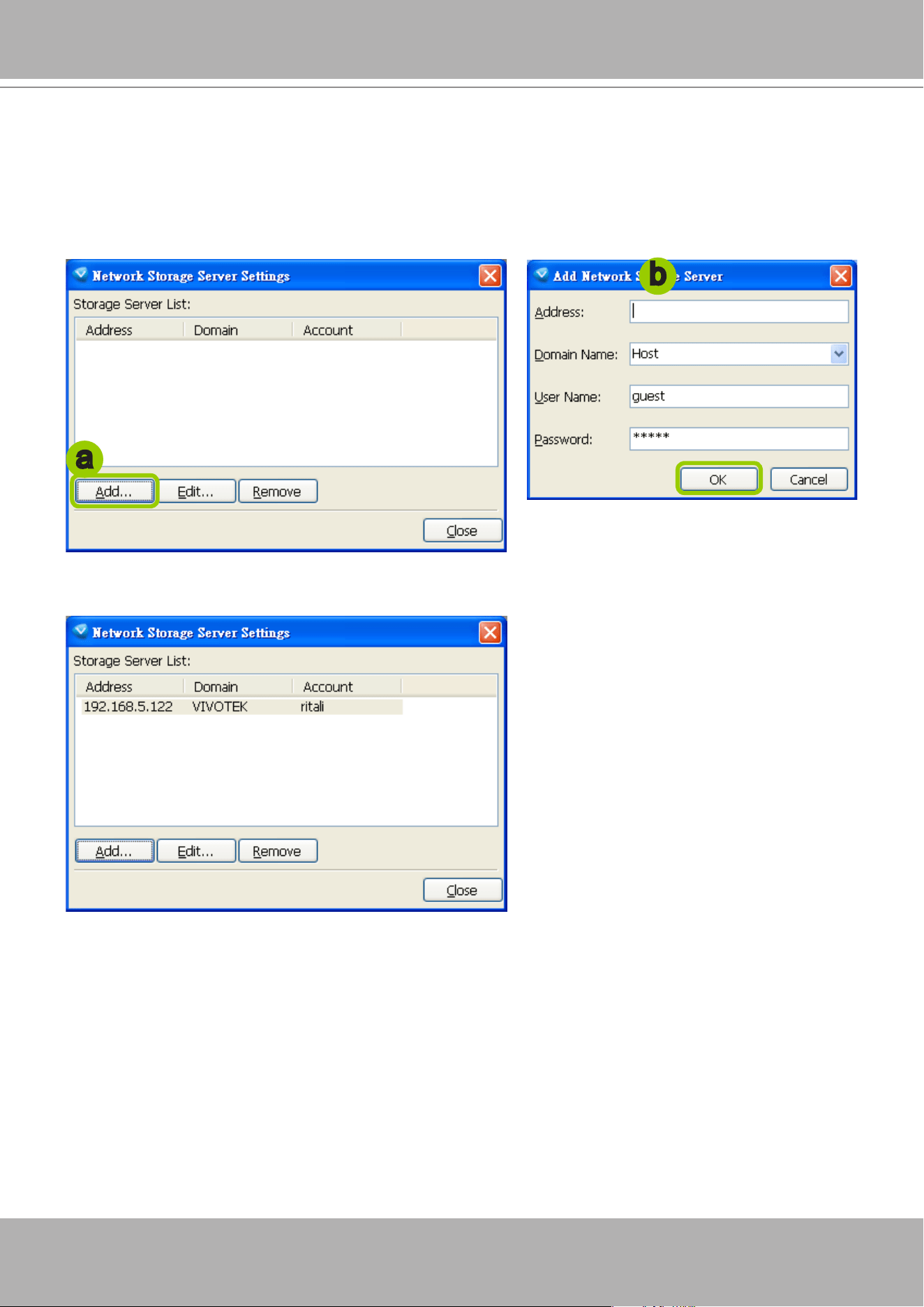
VIVOTEK - A Leading Provider of Multimedia Communication Solutions
214 - User's Manual
Network Storage Server Settings
The VAST Server allows user to set up network storage path(s) for recorded les. Please follow
the steps below to add a new network storage path.
a. Click
Add
to open the Network Host Window.
b. Fill in the related information for the network host. Then click
OK
to save the new settings.
c. If you want to add more network host(s), please repeat step a. b.
a
b
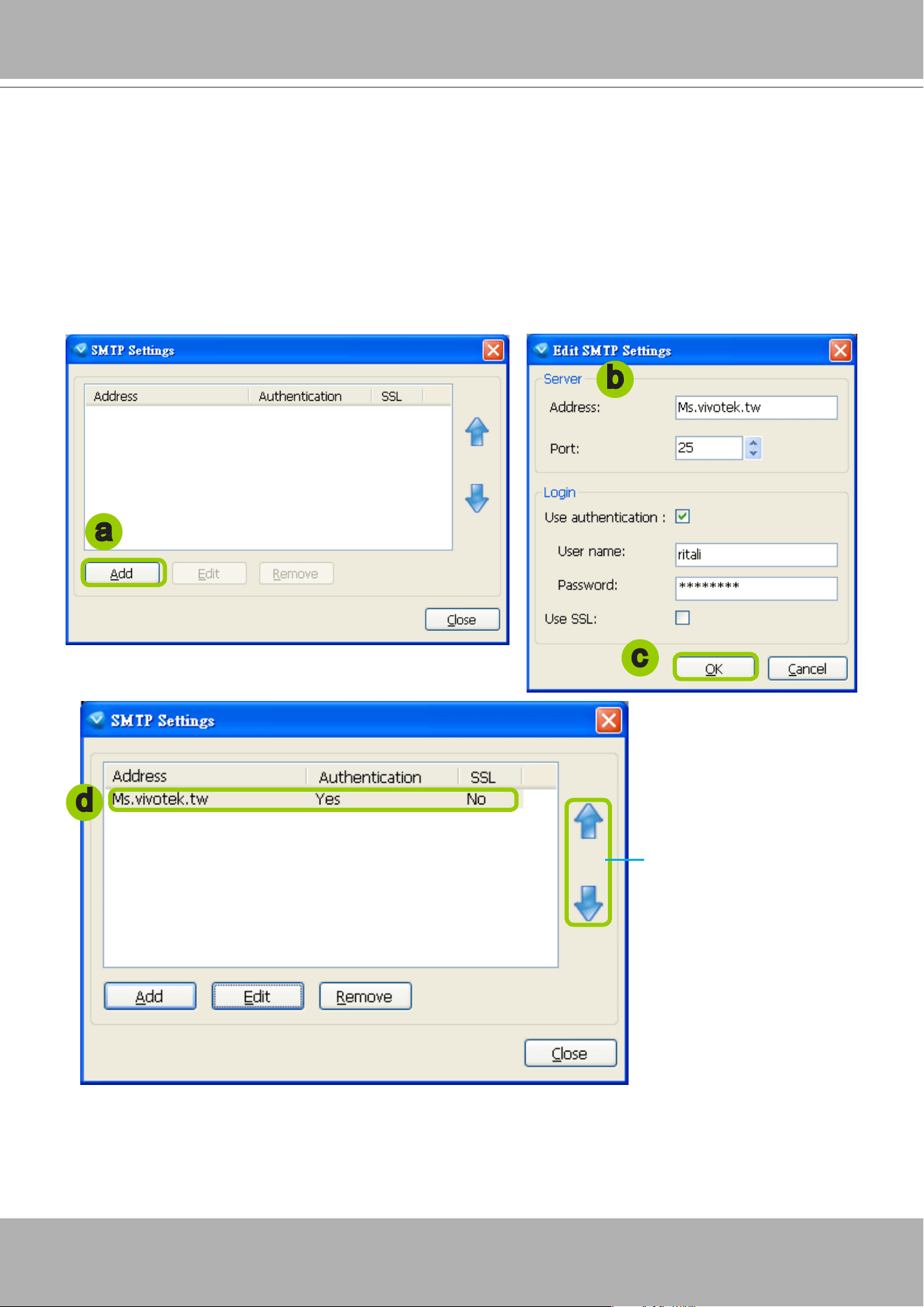
VIVOTEK - A Leading Provider of Multimedia Communication Solutions
User's Manual - 215
SMTP Settings
VAST Server allows user to set up SMTP Server to send mail alert when event triggers. For
more information about how to set up event management, please refer to page 161.
Please follow the steps below to congure the SMTP Server:
a. Click
Add
to open the SMTP Settings page.
b. Enter the related information of your mail server. If your SMTP server requires a secure connection
(SSL), check
Use SSL
.
c. Click
OK
to enable the settings.
d. Then the new information will appear on the SMTP Settings window as shown below.
b
a
c
d
If you have more than
one SMTP server, you
can click to arrange the
priority.
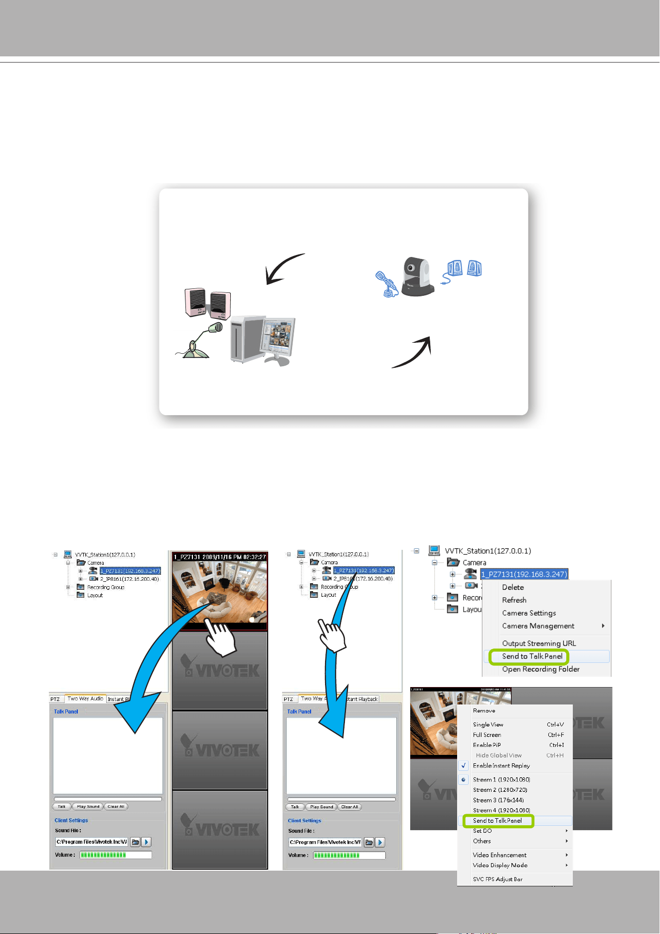
VIVOTEK - A Leading Provider of Multimedia Communication Solutions
216 - User's Manual
How to Use the Talk Panel
VAST LiveClient supports the two way audio function which allows the user to communicate with
people around the network camera. Please enable the two way audio function on the camera
side.
The following is an illustration of the two way audio function:
Add a Camera to the Talk Panel
There are several ways to add a Network Camera to the Talk Panel:
Drag-and-drop a camera from the video cell or from the hierarchical management tree to the talk panel
as shown below. You can also
right-click
the target camera or the video cell, then click
Send to Talk
Panel
on the popup menu.
Audio transmitted from operators
Audio transmitted from network camera
Network Camera with internal
or external microphone
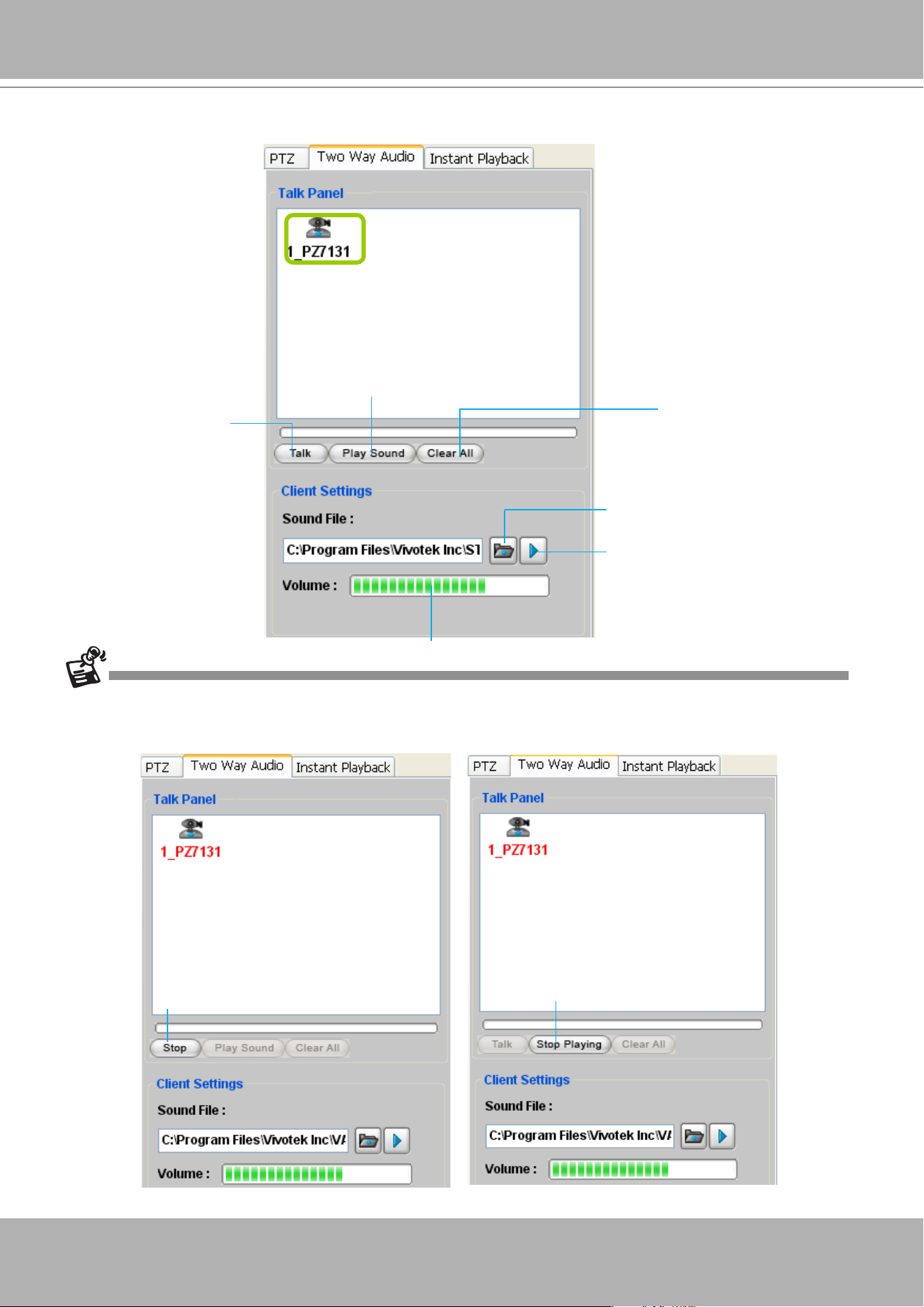
VIVOTEK - A Leading Provider of Multimedia Communication Solutions
User's Manual - 217
An icon with the camera name will be displayed in the Talk Panel.
Please note that you cannot
Talk
and
Play Sound
at the same time.
When you are talking or playing sound, you cannot add other cameras to the Talk Panel. If you want to add more
cameras to the Talk Panel, please
Stop Talking
and
Stop Playing
first.
Click to stop talking
Click to stop playing
Remove all cameras
from the Talk Panel
Click to play sound from the camera
Click to talk
Click to adjust volume
Click to play the selected
sound on the client side
Select sound from the
le list
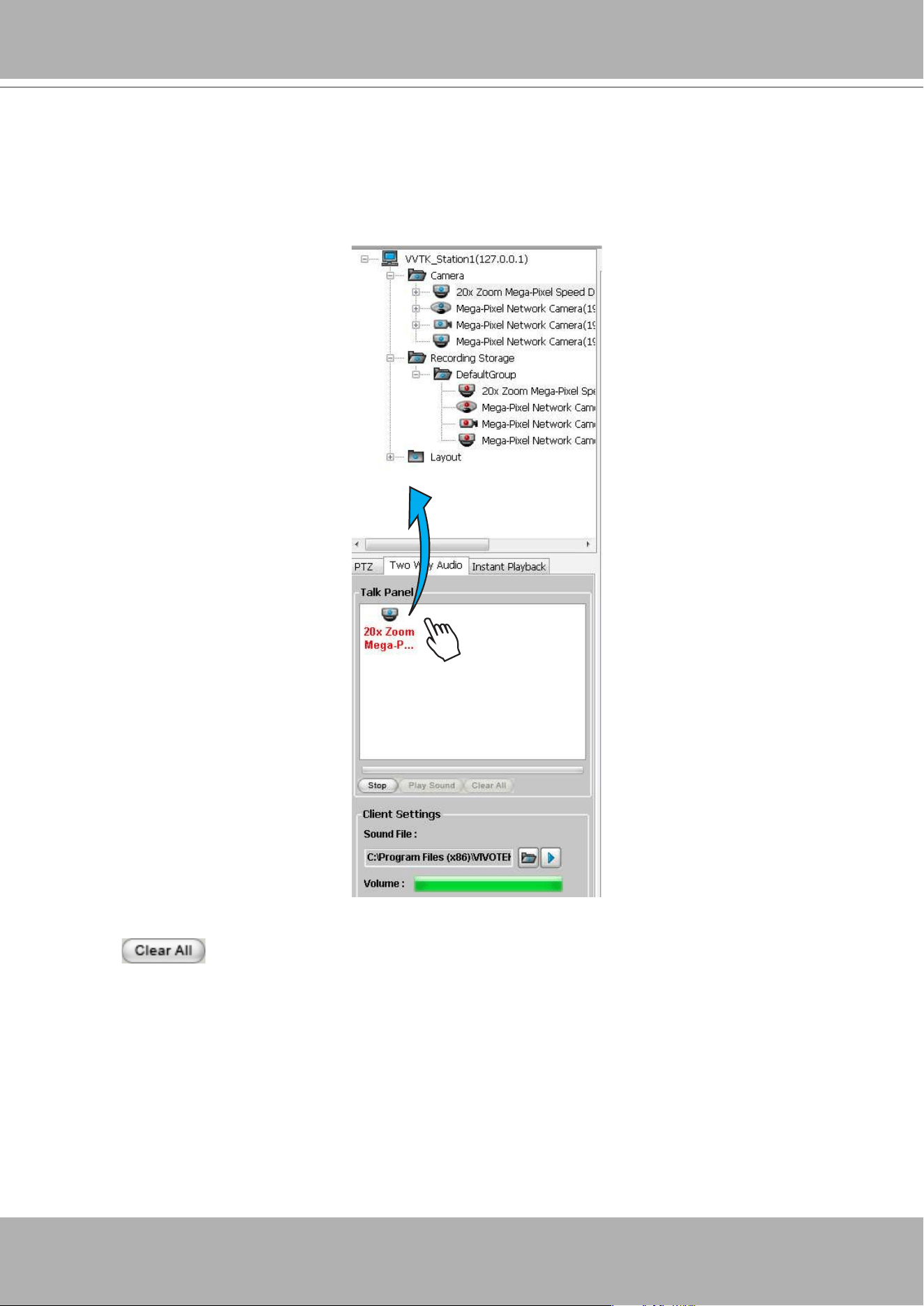
VIVOTEK - A Leading Provider of Multimedia Communication Solutions
218 - User's Manual
Remove a Camera from the Talk Panel
Remove a camera
Drag a camera from the Talk Panel and drop to the hierarchical management tree window as shown
below. The camera icon will disappear.
Remove all cameras
Click
, all cameras in the Talk Panel will be removed.
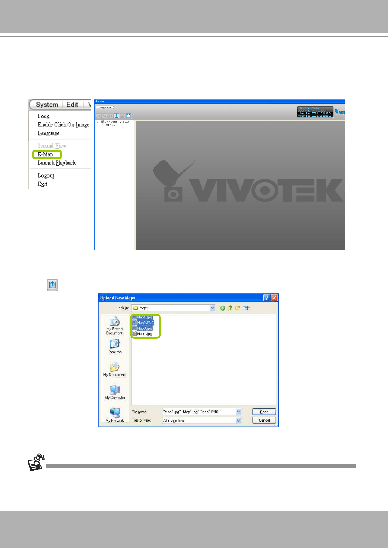
VIVOTEK - A Leading Provider of Multimedia Communication Solutions
User's Manual - 219
How to Congure E-map Settings
VAST LiveClient supports intuitive E-map function which allows users to upload E-maps for
overall devices management.
Click
System > E-map
to open E-map Settings Page:
Upload an E-map
Click
to search for E-map(s) to upload.
The uploaded E-maps will be listed under the E-map list tree.
If the uploading procedure fails, please compress the image size of your map (equal or smaller than 2MB) and try
again.
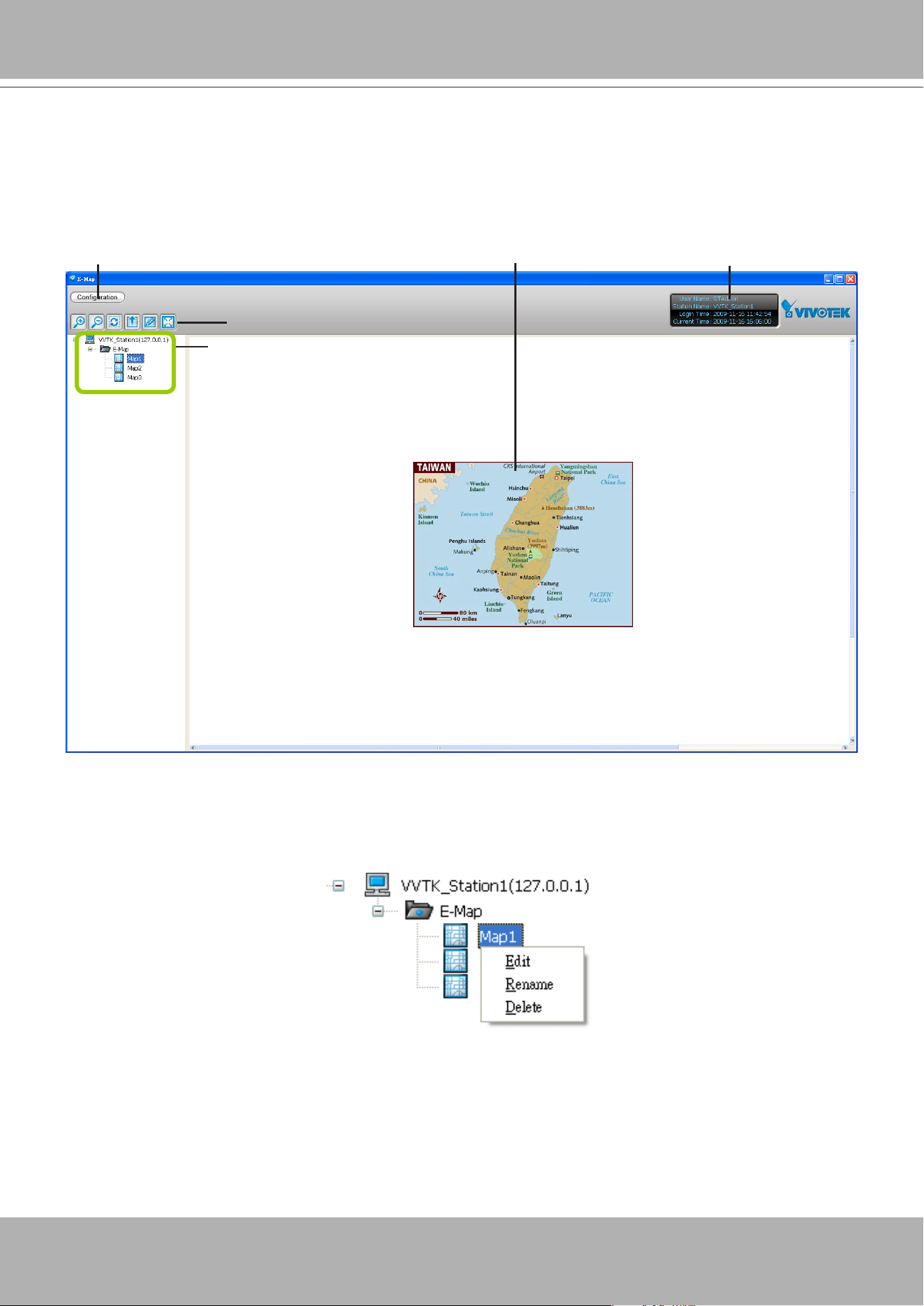
VIVOTEK - A Leading Provider of Multimedia Communication Solutions
220 - User's Manual
User Interface of E-map Settings Page (View Mode)
Double-click
an E-map on the tree, it will be displayed on the E-map window as shown
below. There are two operation modes of E-map settings page: "View Mode" and "Edit Mode".
The following is the "View Mode" illustration.
A. Menu bar B. Quick access bar C. E-map list tree D. E-map window E. Status panel
Right-click
the E-map, then you can
Edit
,
Rename
, or
Delete
the E-map.
B
A
C
E
D
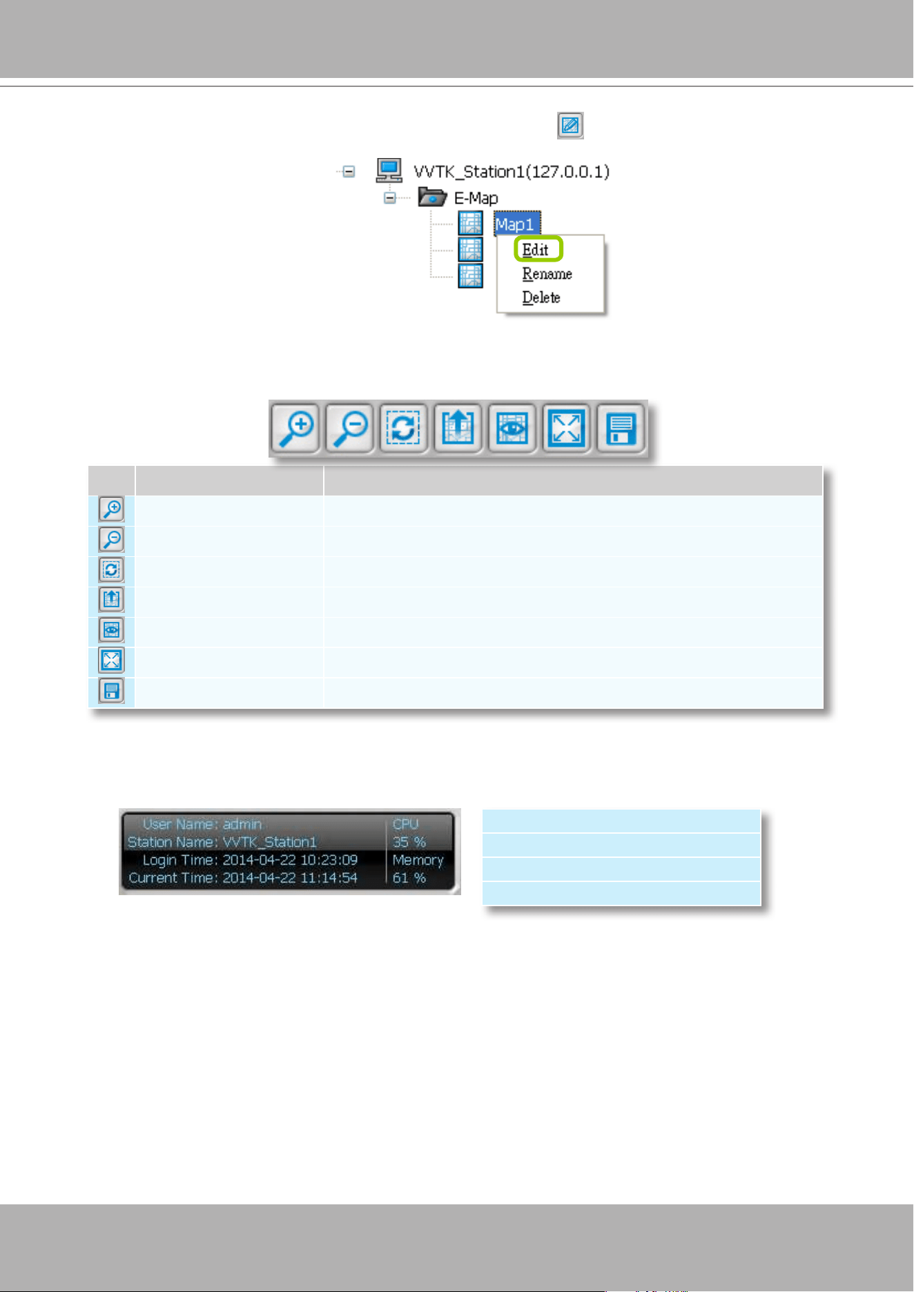
VIVOTEK - A Leading Provider of Multimedia Communication Solutions
User's Manual - 221
Right-click
an E-map on the tree and click
Edit
or click
on the Quick Access Bar, it will
switch to edit mode.
Quick Access Bar
Status Panel
Icon Function Description
Zoom in
Zoom in the E-map
Zoom out
Zoom out the E-map
Default size
Adjust the E-map to default size
Upload
Upload E-map to the login station
View Mode
Click to switch to view mode
Full Screen
Extend the E-map settings page to full screen
Save
Save E-map settings
User Name
Station Name (IP Address)
Login Time (yyyy-mm-dd hh:mm:ss)
Current Time (yyyy-mm-dd hh:mm:ss)
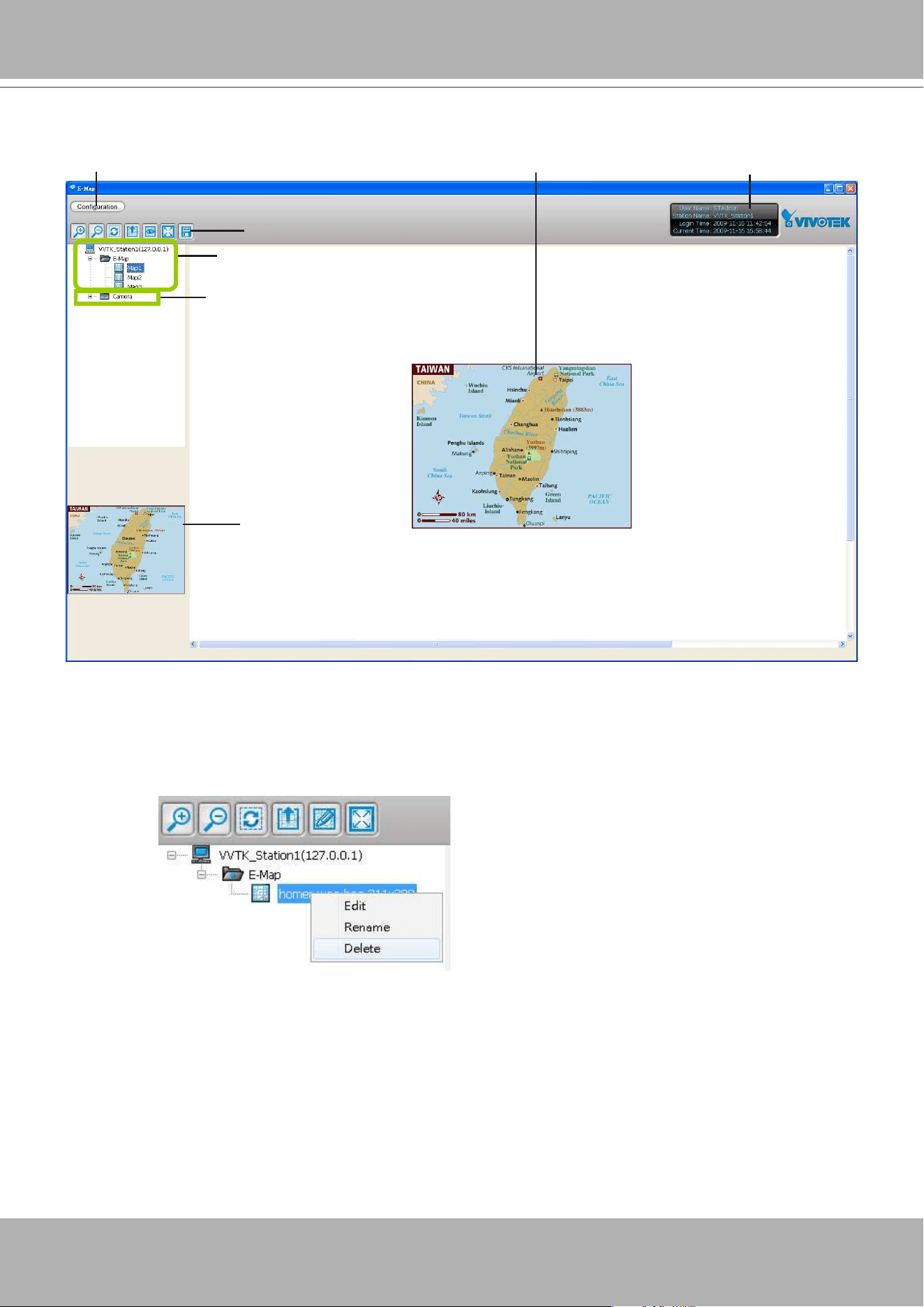
VIVOTEK - A Leading Provider of Multimedia Communication Solutions
222 - User's Manual
User Interface of E-map Settings Page (Edit Mode)
A. Menu bar B. Quick access bar C. E-map list tree D. Device tree
E. Map preview F. E-map window G. Status panel
Right-click
the E-map, you can
Edit, Rename
, or
Delete
the E-map.
B
A
C
D
E
G
F
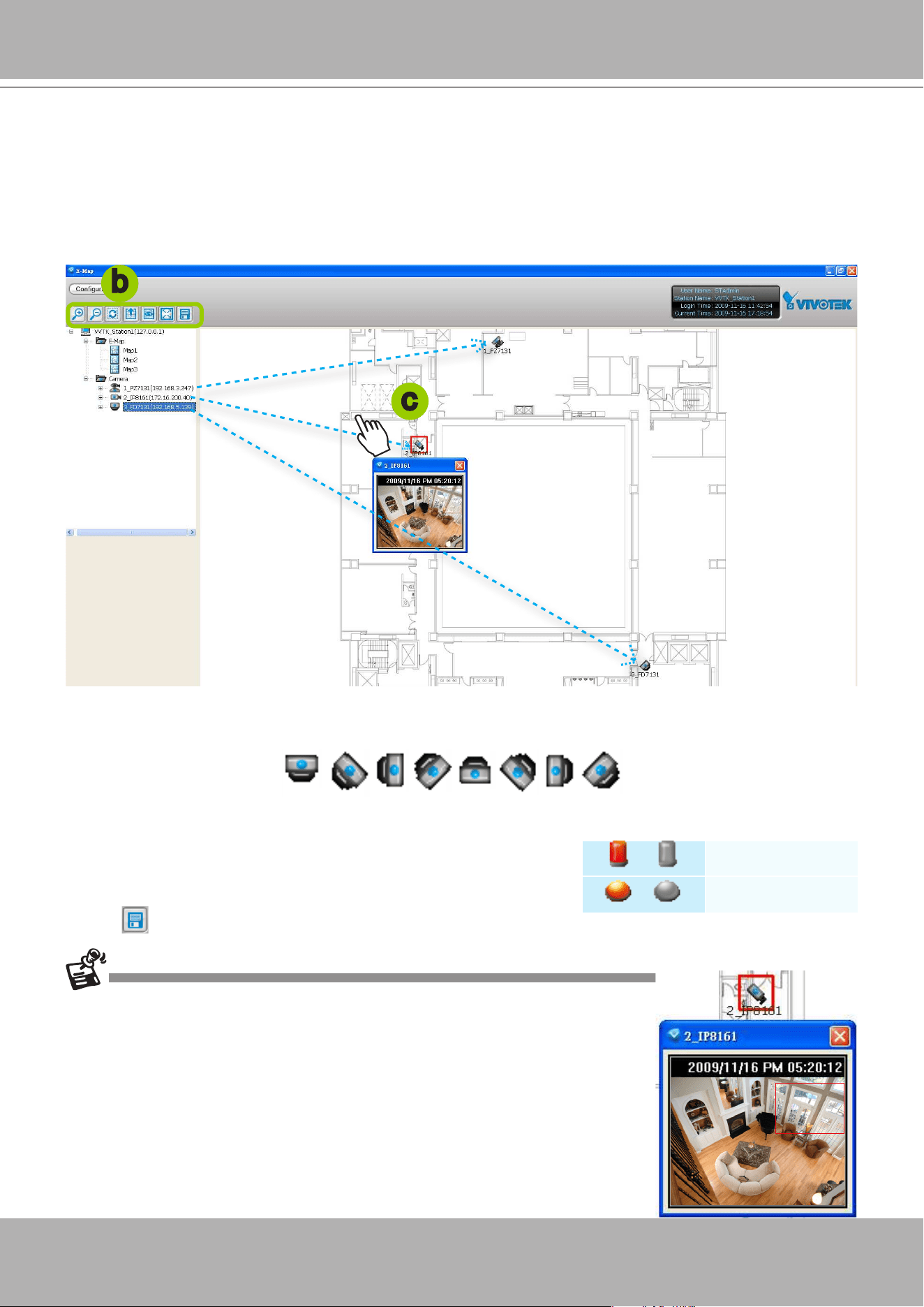
VIVOTEK - A Leading Provider of Multimedia Communication Solutions
User's Manual - 223
Device Management
Please follow the steps below to edit an uploaded E-map.
a.
Double-click
the E-map you want to edit, it will be displayed on the E-map window.
b. Use Quick Access Bar to adjust the size of the E-map. In edit mode, you can also use your mouse to
drag the position of the E-map and zoom in or zoom out the E-map.
c.
Drag-and-drop
the connected devices to the E-map according to your deployment.
d.
Right-click
the device icon on E-map, you can
rotate
the direction or
delete
the device. The device
can be rotated in 8 derections as shown below.
e. You can also drag the DI/DO device under the connected device onto the E-map. If you want to
change the status of the
DO
device,
double click
the DO icon on E-map.
f. Click
on the Quick Access Bar to save the new settings.
b
c
/
Digital input on / off
/
Digital output on / off
The red frame twinkling around the device means there is event trigger(s) going on.
Meanwhile, a live view dialog will pop up beside the model.
For more information about DI/DO settings, please refer to
Association Management on page 159.
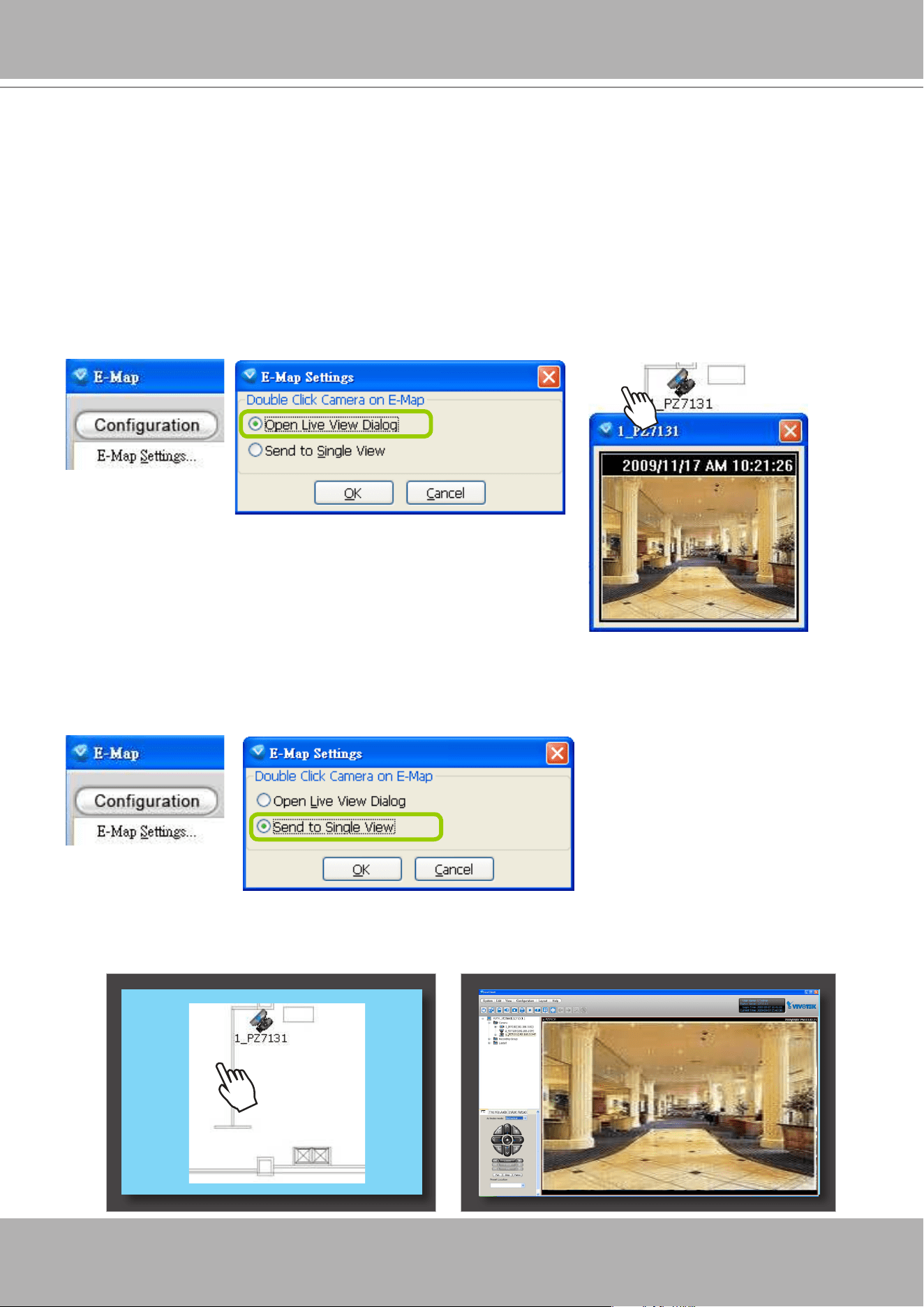
VIVOTEK - A Leading Provider of Multimedia Communication Solutions
224 - User's Manual
Live View Dialog Settings
Click
Configuration
>
E-map Settings
to open the E-map Settings dialog, then you can
choose to
Open Live View Dialog
or to
Send to Single View
when you double-click the device
deployed on the E-map.
Open Live View Dialog
Select
Open Live View Dialog
: When you
double-click
the device icon on the E-map or when an event
triggers, a live view dialog will pop up beside it. It is the default setting in E-map Settings window.
Send to Single View
Select
Send to Single View
: When you
double-click
the device icon on the E-map, it will open a single
view on the VAST LiveClient.
If you have set up dual monitor, it will be automatically sent a single view to the second monitor.
Monitor 1 Monitor 2
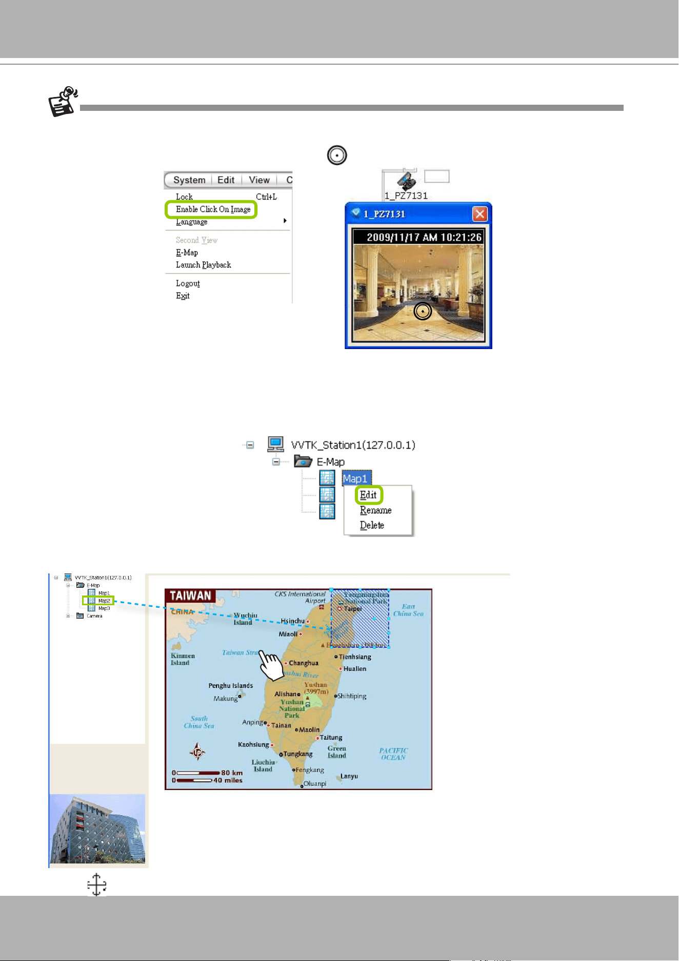
VIVOTEK - A Leading Provider of Multimedia Communication Solutions
User's Manual - 225
E-map Link
After completing device deployment on your E-map, you can link an E-map to another E-map.
Please follow the steps below to congure E-map link:
a. Select a map you want to edit and enter
Edit Mode
.
b.
Drag-and-drop
another E-map onto current E-map. A blue frame will appear as shown below.
For example: Link Map1 to Map2 by dargging Map2 onto Map1
c. Use
to move the position of the blue frame.
The live view dialog also supports
click on image
,
PTZ
, and
e-PTZ
as long as the linked device supports and
enables those functions. To enable those function on E-map, please check the item "Enable click on image" on the
menu bar of LiveClient as shown below. Then an icon will appear in the live view dialog for you to control the
cameras.
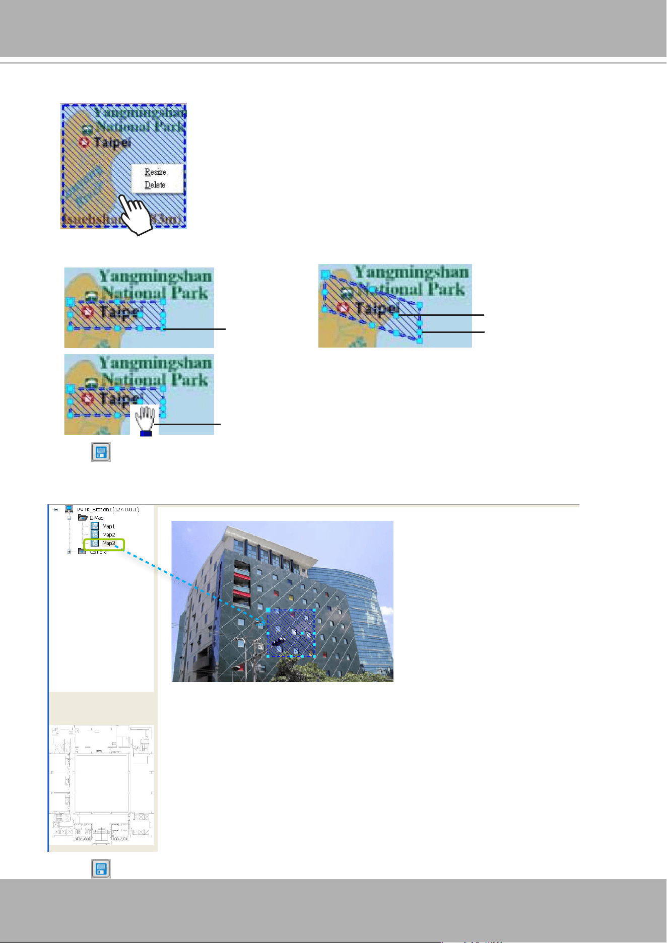
VIVOTEK - A Leading Provider of Multimedia Communication Solutions
226 - User's Manual
d.
Right-click
the blue frame to
Resize
or
Delete
it.
Click
Resize
, some nodes will appear around the blue frame. Then You can drag the nodes to move
the position, rotate the direction, adjust the size, and change the shape.
e. Click on the Quick Access Bar to save the new settings.
f. If you want to set additional map links, please repeat steps a. ~ e.
For example: Link Map2 to Map3 by dargging Map3 onto Map2
g. Click
on the Quick Access Bar to save the new settings.
resize
change the shape
rotate the direction
move the position
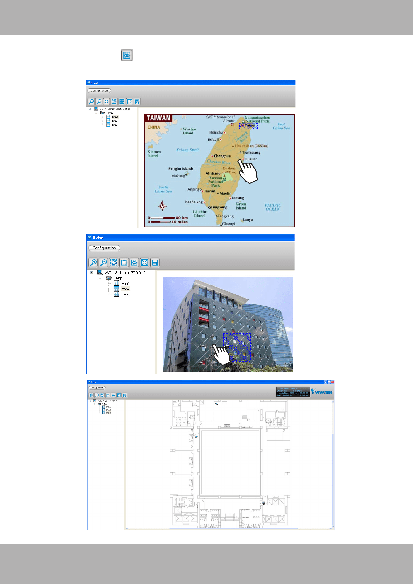
VIVOTEK - A Leading Provider of Multimedia Communication Solutions
User's Manual - 227
h. Test the web links. Click on the Quick Access Bar to switch to view mode.
Double-click
the blue frame on Map1, it will automatically switch to map2. Then
double-click
the blue
frame on Map2, it will automatically switch to map3.
Map 1
Map 2
Map 3
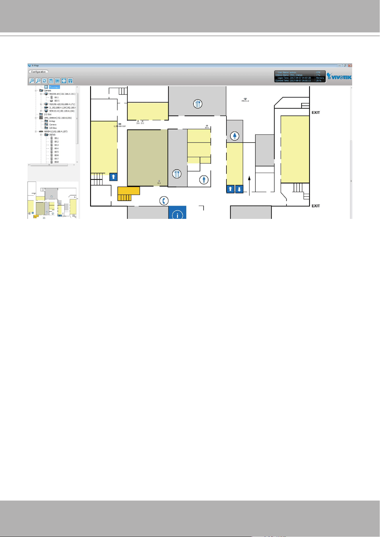
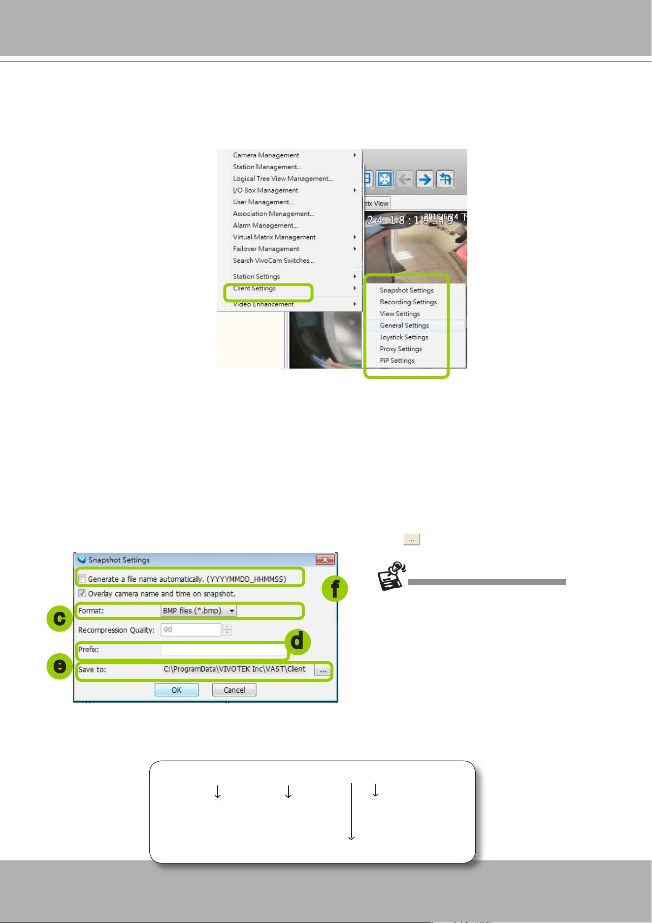
VIVOTEK - A Leading Provider of Multimedia Communication Solutions
User's Manual - 229
How to Congure Client Settings
In Client Settings, you can configure Snapshot Settings, Recording Settings, View Settings,
General Settings, Joystick Settings, Proxy Settings, and PiP Settings.
Snapshot Settings
Please follow the steps below to congure snapshot settings:
a. Click
Conguration > Client Settings > Snapshot Settings
on the menu bar to open the
Snapshot
Settings
window.
b. By default, camera name and current time will be printed on the snapshots taken.
c. Select a picture format for snapshots (
BMP
or
JPEG
). If you select
JPEG
format, you can adjust the
recompression quality (from 1 to 100). Note that a higher value would generate higher picture quality
but lower compression rate.
d. Fill in a lename prex for the snapshots.
e. The default storage path for snapshots is C:\Users\Public\Documents\VIVOTEKInc\VAST\Client\
LiveClient. If you want to change the storage path, click
Browse
to select another folder.
f. If you check
Generate a le name automatically
, VAST will directly save snapshots with the following
lename format to the storage folder.
Snapshot_20100125_173015_01.jpg
File name prex Date and time
(YYYYMMDD_hhmmss)
Serial number of snapshots
Picture format
c
d
e
f
The recompression quality is only enabled
in MPEG-4 streaming. If your stream source
is MJPEG, the system will directly save the
JPEG image without recompression.
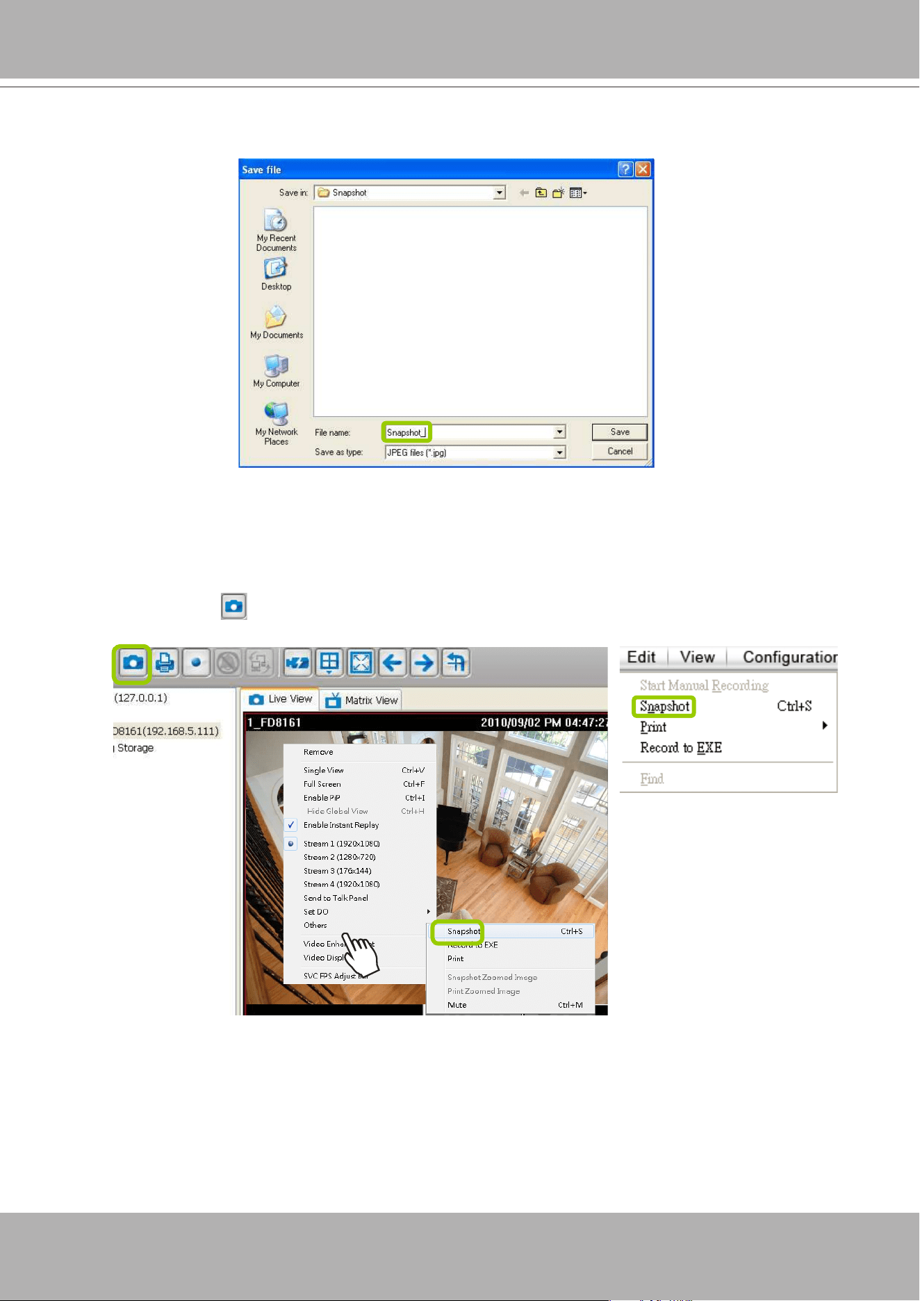
VIVOTEK - A Leading Provider of Multimedia Communication Solutions
230 - User's Manual
If you uncheck
Generate a le name automatically
, the
Save le
dialog box will pop up when you
take a snapshot. The le name prex will automatically be displayed in the Save File dialog box.
Take a Snapshot
Please follow the steps below to take a snapshot of the live video stream:
a. Select the video cell of which you want to take a snapshot.
b. Click
Snapshot
on the quick access bar, or
right-click
the video cell and select
Others >
Snapshot
from the popup menu. You also can click
Edit > Snapshot
to take a snapshot.
c. The snapshots will be found in the preset storage folder on your local computer.
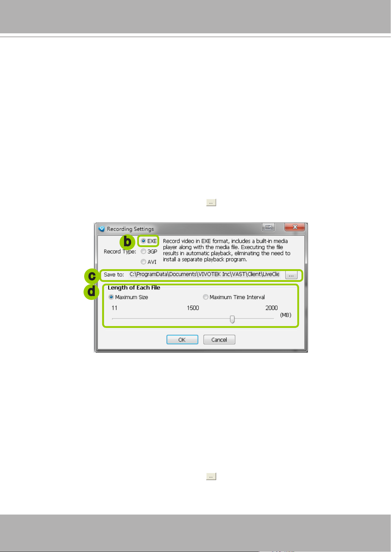
VIVOTEK - A Leading Provider of Multimedia Communication Solutions
User's Manual - 231
Recording Settings
The VAST Server allows you to record the live video in EXE, 3GP, or AVI format to your storage
folder.
Type 1: Record to EXE
Record video as an EXE le. The EXE is not only a media le but also a built-in media player. When
user execute the EXE, the media le will be played automatically. There is no need to install any other
program. For more information about how to use the EXE player, please refer to page 235.
Please follow the steps below to congure EXE record settings:
a. Click
Conguration > Client Settings > Recording Settings
on the menu bar to open the
Recording
Settings
window.
b. Select
EXE
as the Record Type.
c. The default storage path is C:\Users\Public\Documents\VIVOTEK Inc\VAST\Client\LiveClient\Record.
If you want to change the storage path, click
Browse
to select another folder.
d. Select the Length of each file--
Maximum Size
(11~2000MB) or
Maximum Time Interval
(1~150
min).
e. Click
OK
to enable the settings.
Type 2: Record to 3GP
Record video as a 3GP file. 3GP file is a standard MP4 format compatible with players such as VLC
player. Choose this type if you has already installed one of these players.
Please follow the steps below to congure 3GP record settings:
a. Click
Conguration > Client Settings > Recording Settings
on the menu bar to open the
Recording
Settings
window.
b. Select
3GP
as the Record Type.
c. The default storage path is C:\Users\Public\Documents\VIVOTEK Inc\VAST\Client\LiveClient\Record.
If you want to change the storage path, click
Browse
to select another folder.
d. Select the Length of each le--
Maximum Size
(1~2000MB) or
Maximum Time Interval
(1~150 min).
b
c
d
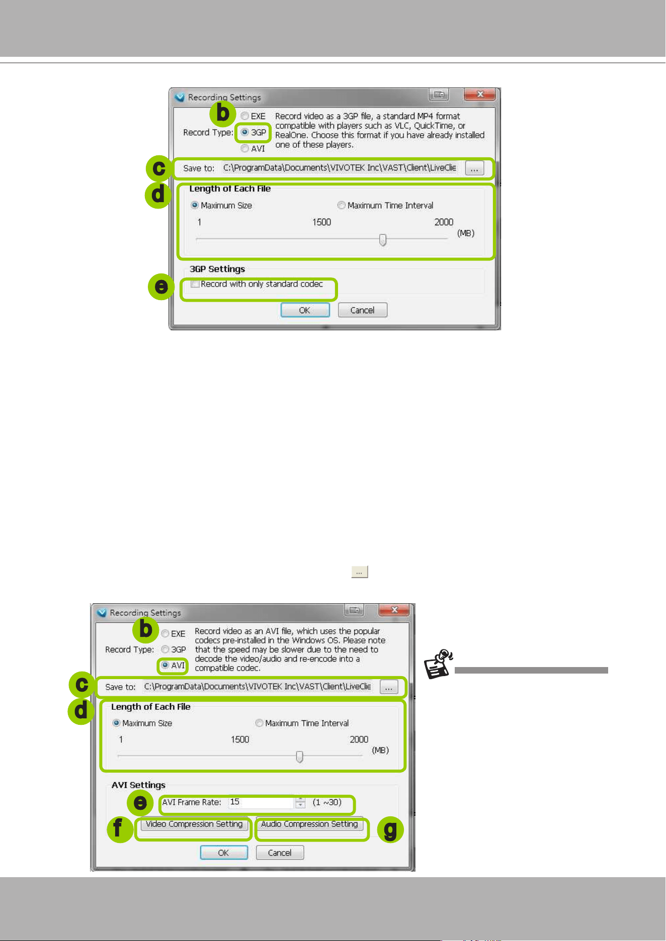
VIVOTEK - A Leading Provider of Multimedia Communication Solutions
232 - User's Manual
e. If you check "Record with only standard codec", the video from old models (VIVOTEK 6000-series
products) using H.263 codec will not be recorded.
f. Click
OK
to enable the settings.
Type 3: Record to AVI
Record video as an AVI le, which uses the popular codecs pre-installed in the Windows OS. Please
note that the speed may be slower due to the need of decoding the video/audio and re-encoding both
into a compatible codec.
Please follow the steps below to congure AVI record settings:
a. Click
Conguration > Client Settings > Recording Settings
on the menu bar to open the
Recording
Settings
window.
b. Select
AVI
as the Record Type.
c. The default storage path is C:\Users\Public\Documents\VIVOTEK Inc\VAST\Client\LiveClient\Record.
If you want to change the storage path, click
Browse
to select another folder.
d. Select the Length of each le--
Maximum Size
(1~2000MB) or
Maximum Time Interval
(1~150 min).
b
c
d
e
b
c
d
e
f g
Due to the AVI file has a limitation on
the maximum file size of 2G bytes, if
the setting “time length” generates data
larger than 2G bytes, several files will
be created.
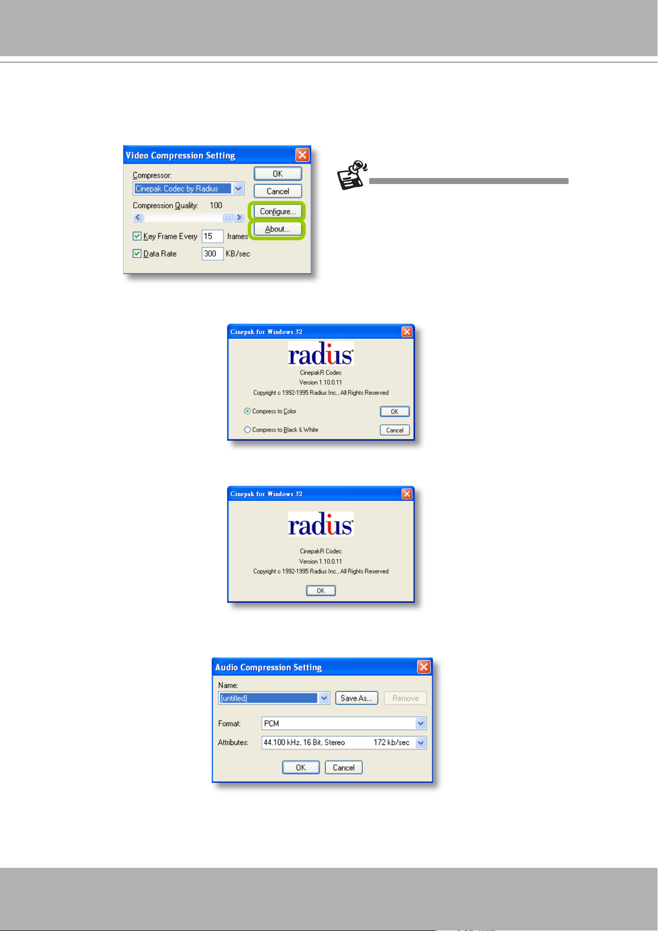
VIVOTEK - A Leading Provider of Multimedia Communication Solutions
User's Manual - 233
e. Select the frame rate/ per second.
f. To modify the video compression settings, click
Video Compression Setting
to open the AVI Video
Compression Setting window. Select the desired
video compression algorithm, compression
quality, key frame intervals,
and
data rate
in the corresponding elds.
To modify the settings of the compression algorithm: Click
Configure
, then a dialog box will pop
up for you to modify the settings. The dialog box will be different according to the compressor you
select.
To read the information of a compression algorithm (its version for instance): Click
About,
and a
dialog box will pop up showing the related information. The dialog box will be different according to
the compressor you select.
g. To modify the audio compression settings, click
Audio Compression Setting
to open the AVI
Audio Compression Setting window. Select the desired
audio quality, format
, and
attributes
in the
corresponding elds.
If you do not choose to compress the video, the
generated AVI will be very large in le size.
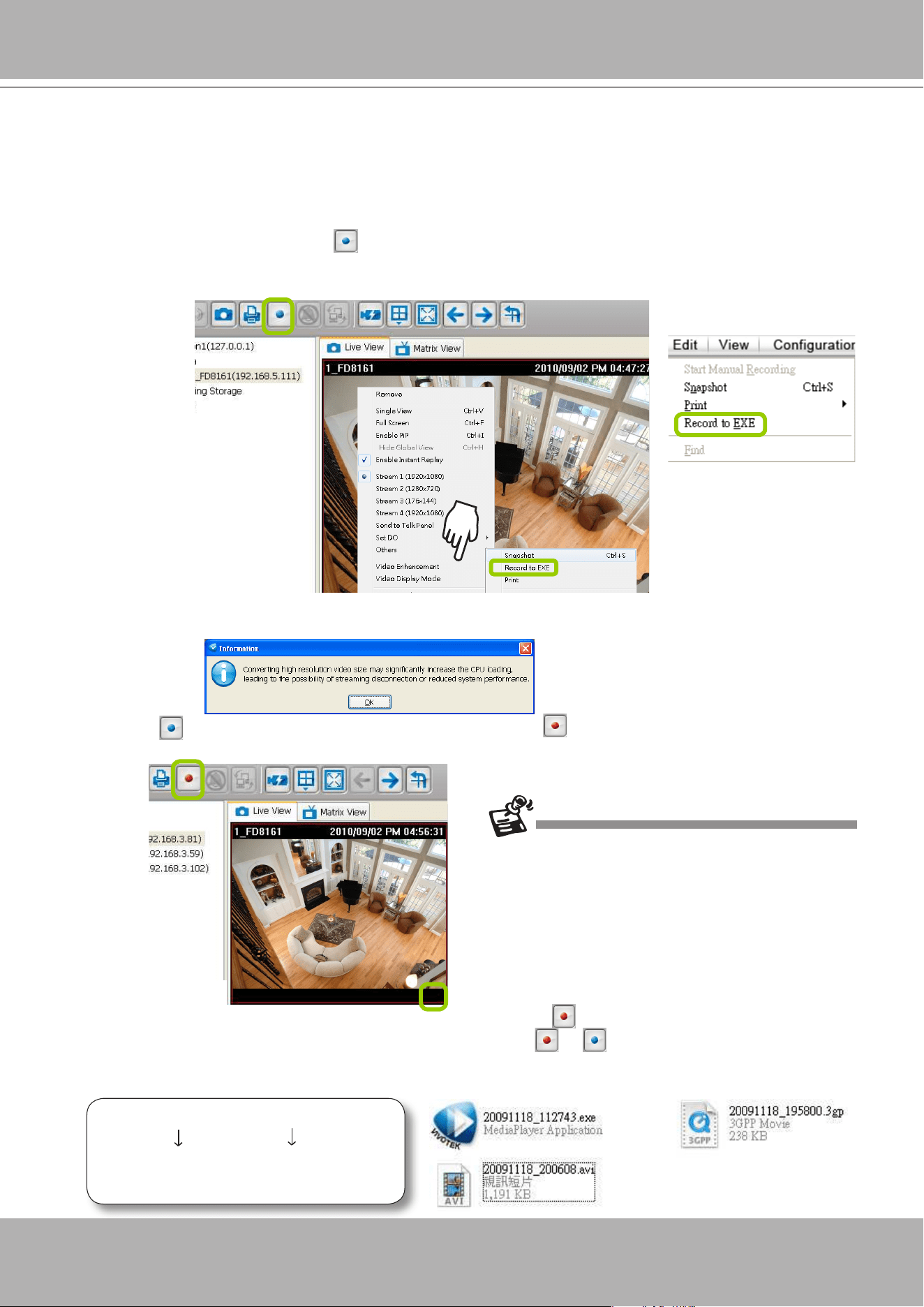
VIVOTEK - A Leading Provider of Multimedia Communication Solutions
234 - User's Manual
Record an EXE/3GP/AVI File
Please follow the steps below to record an EXE/3GP/AVI le of a live video stream:
a. Select a video cell or a device from the heirarchical management tree which you want to record to
media le.
b. Click
Record to EXE/3GP/AVI
on the quick access bar, or
right-click
the video cell and click
Record to EXE/3GP/AVI
. You can also click
Edit > Record to EXE/3GP/AVI
on the menu bar. (The UI
string will change according to your Recording Settings.)
c. For recording a high-resolution video (1600 x 1200) in AVI type, a dialog box will pop up as shown
below to remind you that the CPU loading will increase. Click
OK
to continue the process.
d. The icon
will then change to
Recording EXE/3GP/AVI
, and a red text string (
EXE/3GP/AVI
)
will appear at the bottom right of the video cell. Note that only one video channel can be recorded at a
time.
e. When you want to terminate the AVI Recording, click the icon on the Quick Access Bar. The export
process will then terminate and the button will change from
to . The recorded media les will be
found in the preset storage folder on your local computer as shown below.
Below is the le name format for AVI les:
AVI
20100125_173015.avi
Date and time
(YYYYMMDD_hhmmss)
Video format
If you save your video via a LiveClient installed
on another computer, the videos will be placed in
where you installed the LiveClient utility: e.g.,
C:\\
VAST\Client\LiveClient\Record.
On Windows XP:
C:\Documents and Settings\All Users\Documents\
VIVOTEK Inc\VAST\Client\LiveClient\Record
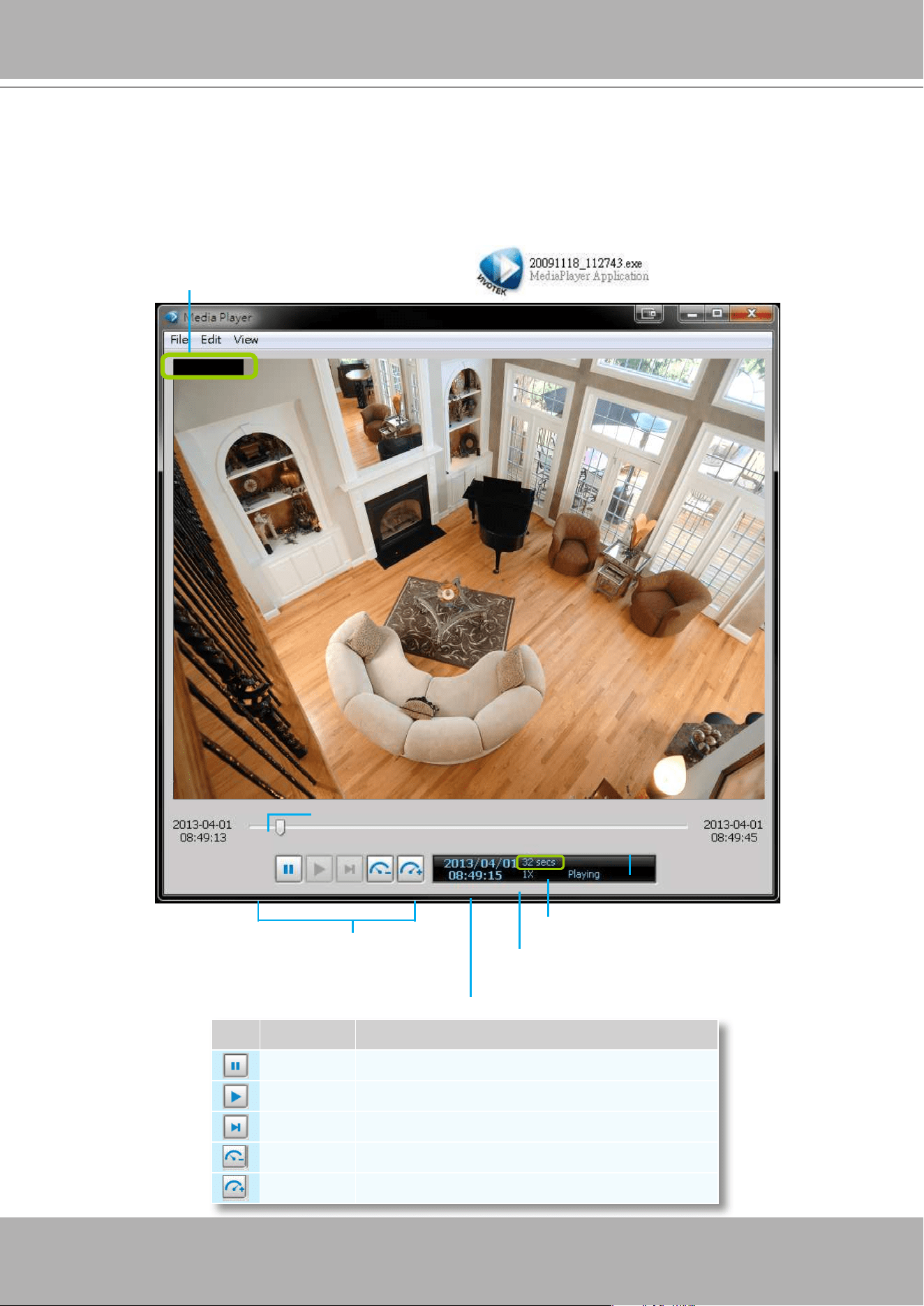
VIVOTEK - A Leading Provider of Multimedia Communication Solutions
User's Manual - 235
Built-in Media Player--EXE
Below is the icon of footages saved as EXE les. Double-click on it, the recorded video will be played
automatically as shown below. You may also open the built-in Media Player in the default location:
C:\Program Files\VIVOTEK Inc\VAST\Client\LiveClient. On Windows XP: C:\Documents and Settings\All
Users\Documents\VIVOTEK Inc\VAST\Client\LiveClient\Record.
Icon Function Description
Pause Pause playback of the focused video clip
Play Start playback of the focused video clip
Next Frame Go to the next video frame of the focused video clip
Slow Down Slow down the playback rate
Speed Up Speed up the playback rate
IP8172
Control Buttons
Timeline Slider
Status Panel
Current time of the video clip
Total length of the histogram
The playing rate can be 1/8, 1/4, 1/2, 1X, 2X,
4X.
Video Title
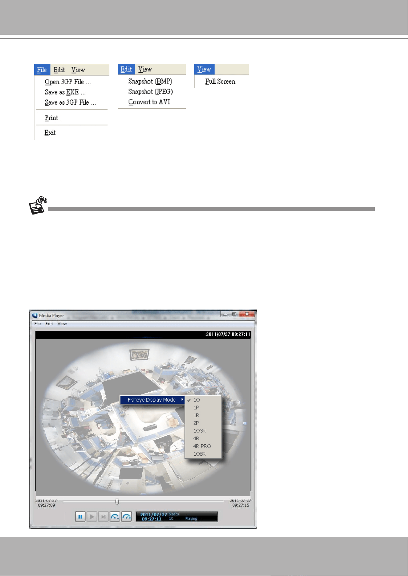
VIVOTEK - A Leading Provider of Multimedia Communication Solutions
236 - User's Manual
The function menu of the built-in media player are displayed as shown below:
The built-in player is able to playback 3GP and EXE les.
The built-in player is able to save 3GP les as EXE les.
The built-in player is able to save EXE les as 3GP les.
The built-in player is able to convert EXE and 3GP les into AVI les.
The built-in player also supports snapshot and print functions.
Below are special notices related to video recording with the sheye cameras:
For recorded videos from the fisheye cameras, only the built-in Media Player can playback the
Regional
or
Panoramic
views. If you access the recorded videos using other playback software, you
will end up seeing the circular-shape Original view.
When recording videos from sheye cameras, Regional and Panoramic views can only be preserved in
the EXE and 3GP format. If you save the dewarped views, i.e., Regional and Panoramic, as AVIs, only
the circular Original view will be preserved.
Currently the video playback on the Emap window displays the Original view only.
To display a Regional or Panoramic view, right-click on the Media Player window.
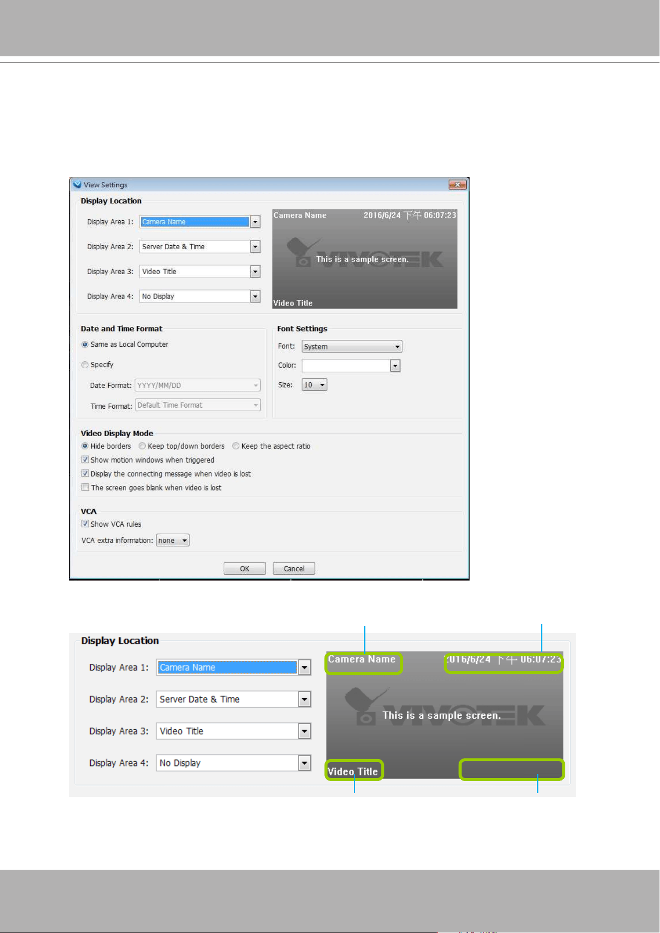
VIVOTEK - A Leading Provider of Multimedia Communication Solutions
User's Manual - 237
View Settings
This section allows you to set the display mode of a video cell, including
Display Location,
Date and time Format, Video Display Mode,
and
Font Settings
. When you change the
settings, the sample window will change accordingly for you to preview the settings.
Display Location
As the illustration shows, there are 4 display areas for you to input information about the live video. Each
drop-down list includes many options for you to select:
No display, Camera Name, Video Title, Camera
Date & Time,
Camera DateTime, Server Date & Time, Codec & Resolution, Address,
and
Network
throughput & FPS.
Display Area 1
Display Area 2
Display Area 3 Display Area 4
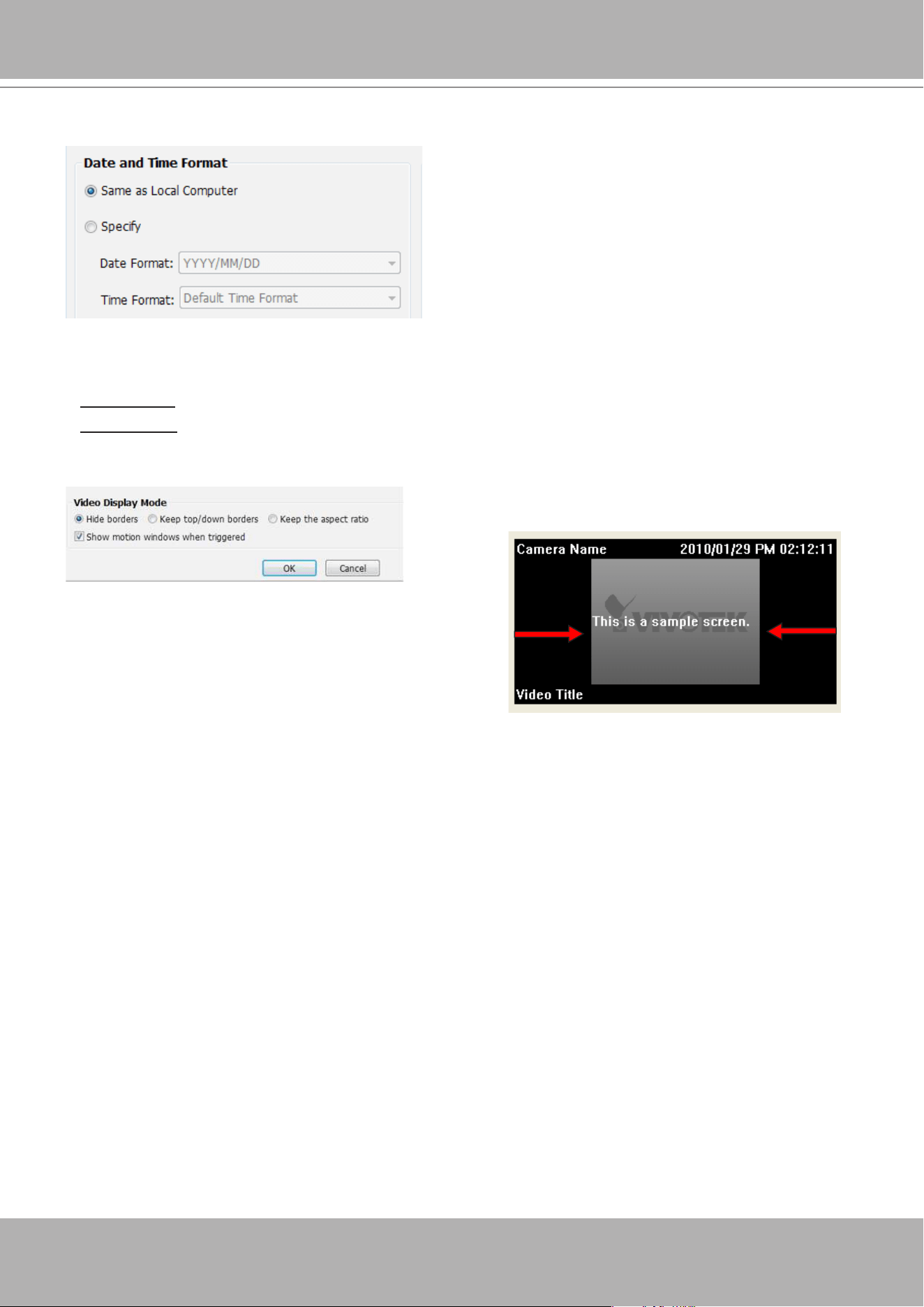
VIVOTEK - A Leading Provider of Multimedia Communication Solutions
238 - User's Manual
Date and Time Format
Same as local computer: Select this option and then the date and time format will synchronize with the
local computer.
Specify: Select a desired format for the date and time from the drop-down list.
Date format
: Select YYYY/MM/DD or MM/DD/YY.
Time format
: Select the default time format (synchronize with the local computer), 12h AM/PM, or 24h.
Video Display Mode
Show motion window when triggered: If you select this option, the red frame of the motion detection
window will appear in the video window when motion is triggered. This function is enabled as default.
Display the connecting message when video is lost:indow will appear in the video window when motion
is triggered. This function is enabled as default.
Show VCA rules: VCA rules refer to the Line Crossing and Field Detection lines drawn on individual
video screens. These VCA functions are configured on the web consoles with cameras, not on the
VAST LiveClient.
For detailed information about how to set up the layout of the live view window, please refer to
How to
Change Video Viewing Mode
on page 131.
Keep the aspect ratio: In the default settings, the size of
the video window will change according to the layout of
the live view window you choose. However, the frame
size may be distorted.
Keep the aspect ratio: If you select
Keep the aspect ratio
, the video window will be adjusted to the
same frame size as the preview window. This function is disabled as default.
The Display options can also be accessed by a right-click on the view cell.
Keep top/down borders: the camera name, video title,
and time will be displayed on the black borders instead
of displaying floating text on the screen.
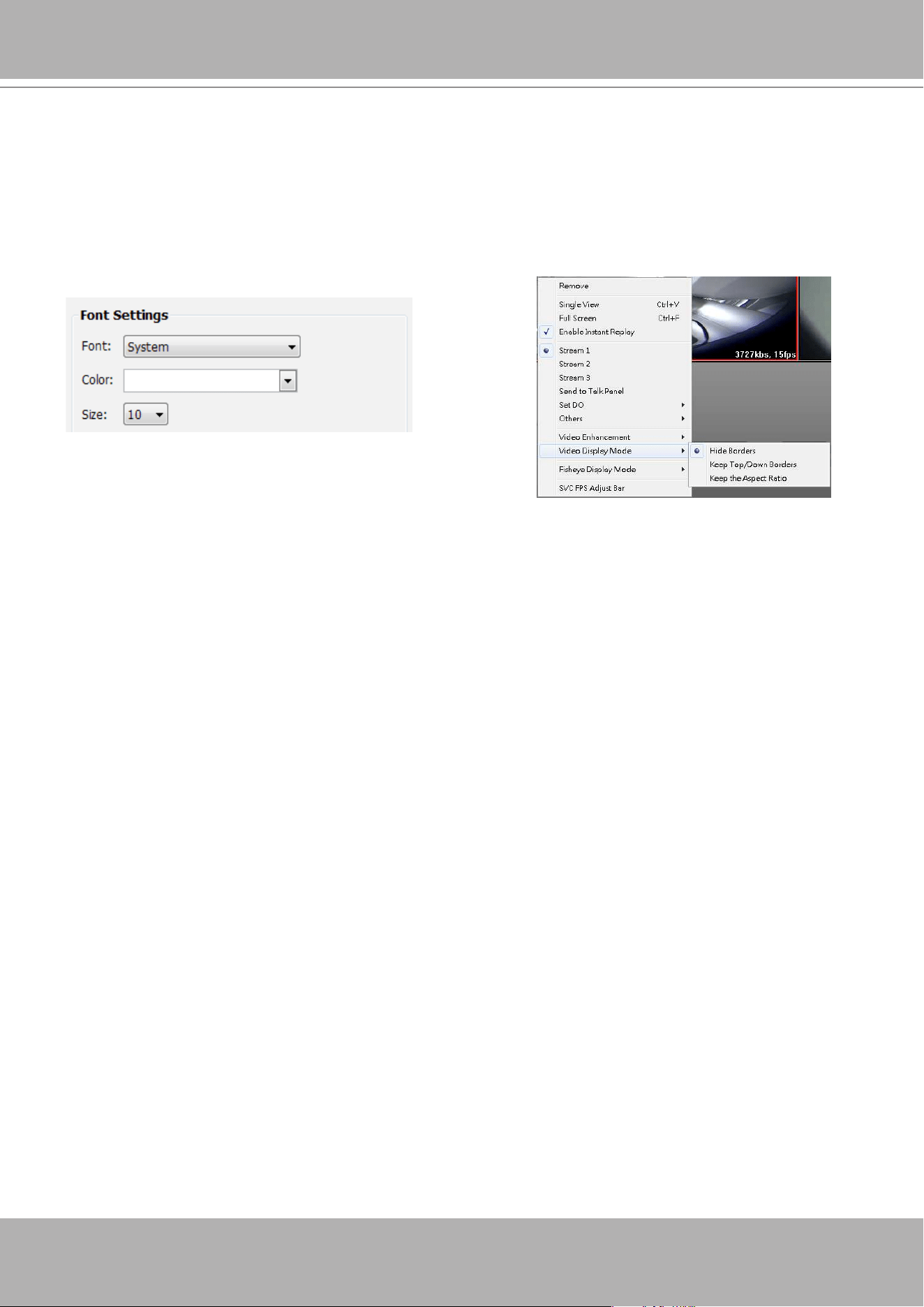
VIVOTEK - A Leading Provider of Multimedia Communication Solutions
User's Manual - 239
Font Settings
This function allows you to change the font on the video cell.
Font: Automatically lists all fonts installed on your operating system. Select the desired type.
Color: Select a desired font color (white, red, green, blue).
Size: Select a desired font size (8, 10, 12, 14).
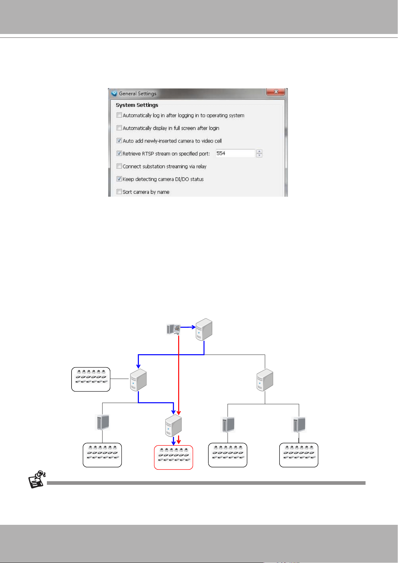
VIVOTEK - A Leading Provider of Multimedia Communication Solutions
240 - User's Manual
General Settings
This section allows you to congure the
System Settings
and
Rotation Settings
.
System Settings
Auto login after logging in to operating system: If you check this option, VAST LiveClient will
automatically login after you login to Windows without filling in the user name and password. This
function is disabled as default.
Automatically display in full screen after login: If you check this option, the video cells will be displayed
in full screen without showing the menu bar or the control panels.
Auto add newly-inserted camera to video cell: If you check this option, VAST LiveClient will
automatically add the newly-inserted device to a video cell. This function is enabled as default.
Retrieve RTSP streaming on specific port: The default port for RTSP streaming is 4543. If you want to
change this port, please check this item and fill in a desired port number.
Setup substation streaming via relay: This option is not checked by default. As the following diagram
shows, VAST Client might directly connect to the streaming under VAST Server 3-2 without requesting
the connection via VAST Server 1 and Server 2-1. If you want to get streaming through relaying,
please check this option.
If the VAST Server 3-2 is set up behind a firewall, the VAST Client will not be able to access the VAST Server 3-2
directly. You have to get the connetion by relaying.
VIVOTEK IP CameraVIVOTEK IP Camera
ST7501
Server 3-1
VAST
Server 1
VAST
Client
VAST
Server 2-1
VIVOTEK IP CameraVIVOTEK IP Camera
VAST
Server 3-2
VIVOTEK IP CameraVIVOTEK IP Camera
VIVOTEK IP CameraVIVOTEK IP Camera
ST7501
Server 3-3
VAST
Server 2-2
VIVOTEK IP CameraVIVOTEK IP Camera
ST7501
Server 3-4
manages 2 sub-stations
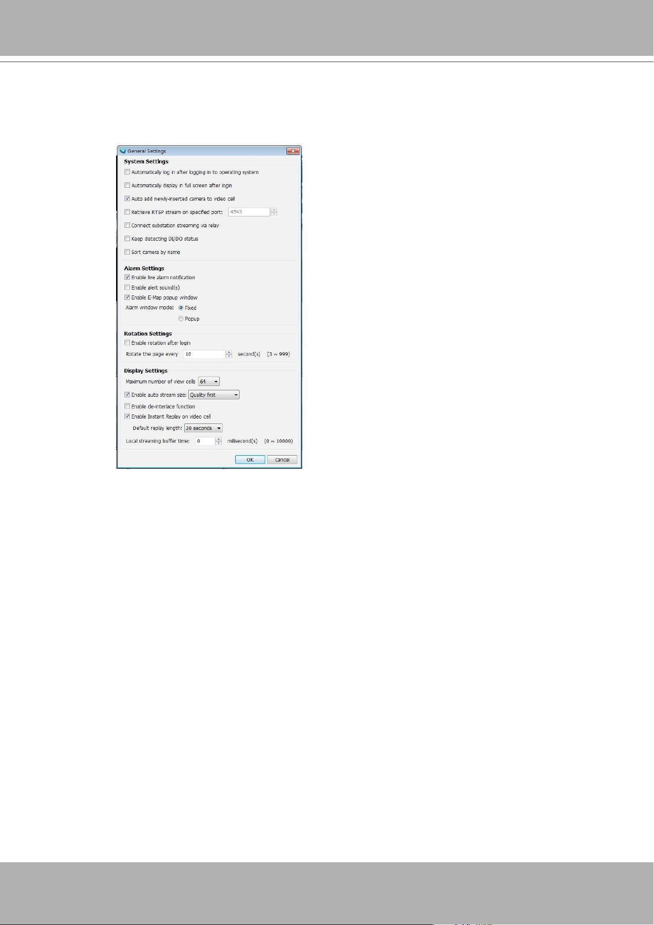
VIVOTEK - A Leading Provider of Multimedia Communication Solutions
User's Manual - 241
Alarm Settings
Enable live alarm notification: Select this option to activate real-time event notification. For example:
the event notification of DI/O status on the hierarchical management tree, the event list in the event
window, motion detection windows in video window, or the event notification on E-map settings page,
etc. This function is enabled as default.
Enable alert sound(s): If you enable this option, you will hear alert sound on the client side when the
event is triggered.
Enable E-Map popup window: When enabled, a popup window appears on an E-map displaying the
current video when a camera-related event occurs.
Note the following with the E-Map popup window:
• The camera that triggers an alarm must be placed on the E-map to have its live video displayed in
the popup window.
• When an event occurs, and the related camera is configured into multiple E-maps, the popup
window appears on the first available E-map.
• When many popup windows appear, many map views will consecutively appear until all popup
windows properly display.
• This feature supports popup windows for cameras under VAST substations or NVR.
• Popup windows only appear when the E-Map is opened; however, the windows will still appear on
a live view.
• If a DI/DO trigger is not associated with a specific camera, no popup video window will appear
when triggered.
• Fisheye dewarp is also available on the E-map popup windows.
Keep detecting camera DI/DO status: The default for this option is enabled. This option enables the
VAST server to monitor the DI/DO status from the configured cameras. You may also disable this
option.
Sort camera by name: The positions of cameras on the device tree will be sorted by their camera
names.
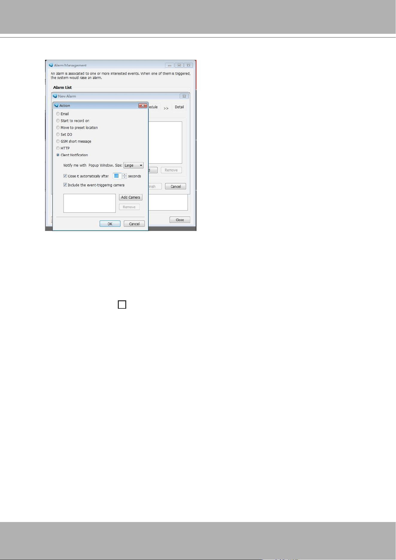
VIVOTEK - A Leading Provider of Multimedia Communication Solutions
242 - User's Manual
Alarm window mode: Select
Fixed
or
Popup
mode for the event window. For more information about
event window, please refer to page 89.
Rotation Settings
Enable rotation after login: If you check this option, the video cells will start to rotate after you login to
the VAST LiveClient. The default setting of this function is disabled.
Rotate the page every
second(s): Fill in a desired interval time for video page rotation. The
maximum value is 99 seconds. The default value is set at 6 seconds.
For detailed information about how to set up the layout of the monitoring window and rotation functions,
please refer to
How to Change Video Viewing Mode
on page 131.
• Please also configure the Client Notification options in the Alarm Management window.
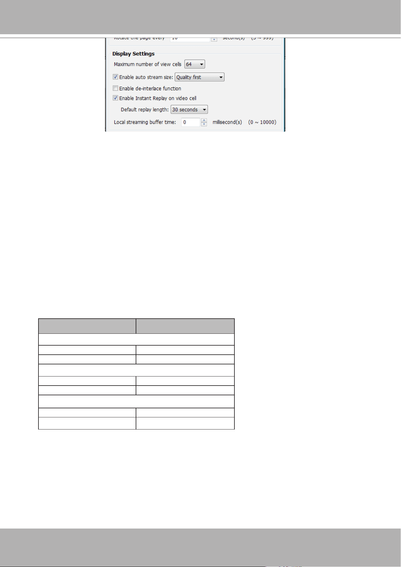
VIVOTEK - A Leading Provider of Multimedia Communication Solutions
User's Manual - 243
Display Settings
Maximum number of view cells
: This determines the number of view cell on window, and also takes
effect with the number of layout pages. For example, if there are 320 channels using the 1+31 layout,
there will be 10 layout pages in the LiveClient window. The configuration changes take effect after the
LiveClient is re-started.
Enable
auto stream size
: The Auto Stream Size feature dynamically adjusts the stream sizes of video
feeds from network cameras in order to reduce CPU load and bandwidth consumption.
It is often the case that in surveillance deployments the physical dimensions of monitors, the
effectiveness of visual stimulus, and the operators' regions of interest can all be very limited.
Streaming large-size videos at all times will be a waste of bandwidth and system computing power.
CIF and VGA size videos are usually sufficient for the operators watching surveillance screens.
When enabled, your LiveClient station automatically requests smaller-size streams as video feeds (any
from streams #1 ~ #4) from the network cameras. For example, the frame size of video stream #4 will
be reduced to 320x240 (CIF). Depending on the actual size of view cells on the LiveClient monitoring
screen, the VAST server automatically requests different video streams.
When the size of view cells is manually expanded, a VAST server requests a different stream. This is
called
Stream Jump
. Shown below are the details of the corresponding stream jumps.
View cell size Stream jump to...
4:3 resolutions
<= 320x240 stream #4 (CIF)
> 320x240 or 640x480 stream #1
16:9 resolutions
<= 384x216 stream #4 (CIF)
> 384x216 or 640x360 stream #1
1:1 (sheye cameras)
<= 384x384 stream #4 (CIF)
> 384x384 or 640x640 stream #1
Facts about Auto Stream Size:
• The Auto Stream Size takes effect when,
1. The size of view cell is changed.
2. Inserting a new camera, or when the "Auto add newly-inserted camera" feature is applied.
3. Double-click or click-and-drag cameras into view cells.
4. When Auto Stream Size feature is enabled (the configuration on this window).
5. Through the layout change.
• The LiveClient utility automatically adjusts stream selection according to the size of view cells, no
user's configuration is required.
VIVOTEK - A Leading Provider of Multimedia Communication Solutions
244 - User's Manual
Enable de-interlace function: Select this option if your connected device does not support de-interlace
function. For example: VS7100.
Enable Instant Replay on video cell: Here you can change the duration of a playback that happened
immediately before a user utilizes the instant playback function.
Local streaming buffer time: Video frames can be temporarily stored on the cache memory of the
VAST server for a short, configurable period of time before they are displayed on the Liveview. If the
networking condition is less than ideal, this can help delivering a smooth video stream. Note that this
feature is not available on a Matrix view and the web console.
Limitations:
• For older, single-stream cameras, the Auto Stream Size feature does not take effect.
• When the Auto Stream Size feature is enabled, the NR and ND series NVR configured under the
VAST server will be considered as substations. The stream configuration of cameras managed by
these NVR substations will not be changed. Only the video codec, bit rate, and frame rate of the
video feeds directed through these NVR substations will be changed into a more economic setting.
• For the NR8401 NVR, the Auto Stream Size function may not fully apply. For cameras managed
by the NR8401, the following will apply:
Large view cell: default viewing stream.
Medium view cell: stream #2.
Small view cell: the last stream.
• a user disables the Auto Stream Size function later, the frame size of stream #4 will not be
restored to the previous configuration.
• The frame size of stream #1 is user-configurable. The VAST server only resizes stream #4.
• If a user disables the Auto Stream Size function later, the frame size of stream #4 will not be
restored to the previous configuration. Stream jump takes place on the display of all connected
cameras once the function is enabled.
• The Auto Stream Size function does not apply to the Matrix view.
• If users configured a region of interest before the Auto Stream Size function is applied, e.g., via
the ePTZ control, the view cell might display a different live view.
• Below is the general rule for stream selection:
stream # congured into VGA stream # congured into CIF
4 streams cameras
Stream 2 Stream 4
3 streams cameras Stream 2 Stream 3
2 streams cameras none Stream 2
• When a smaller stream is selected, the video quality is set to fixed quality as Good.
• The Maximum frame rate is not configured.
• The VAST server automatically selects a video resolution of a specific aspect ratio that best fits
the current view cell, and places the video into the view cell.
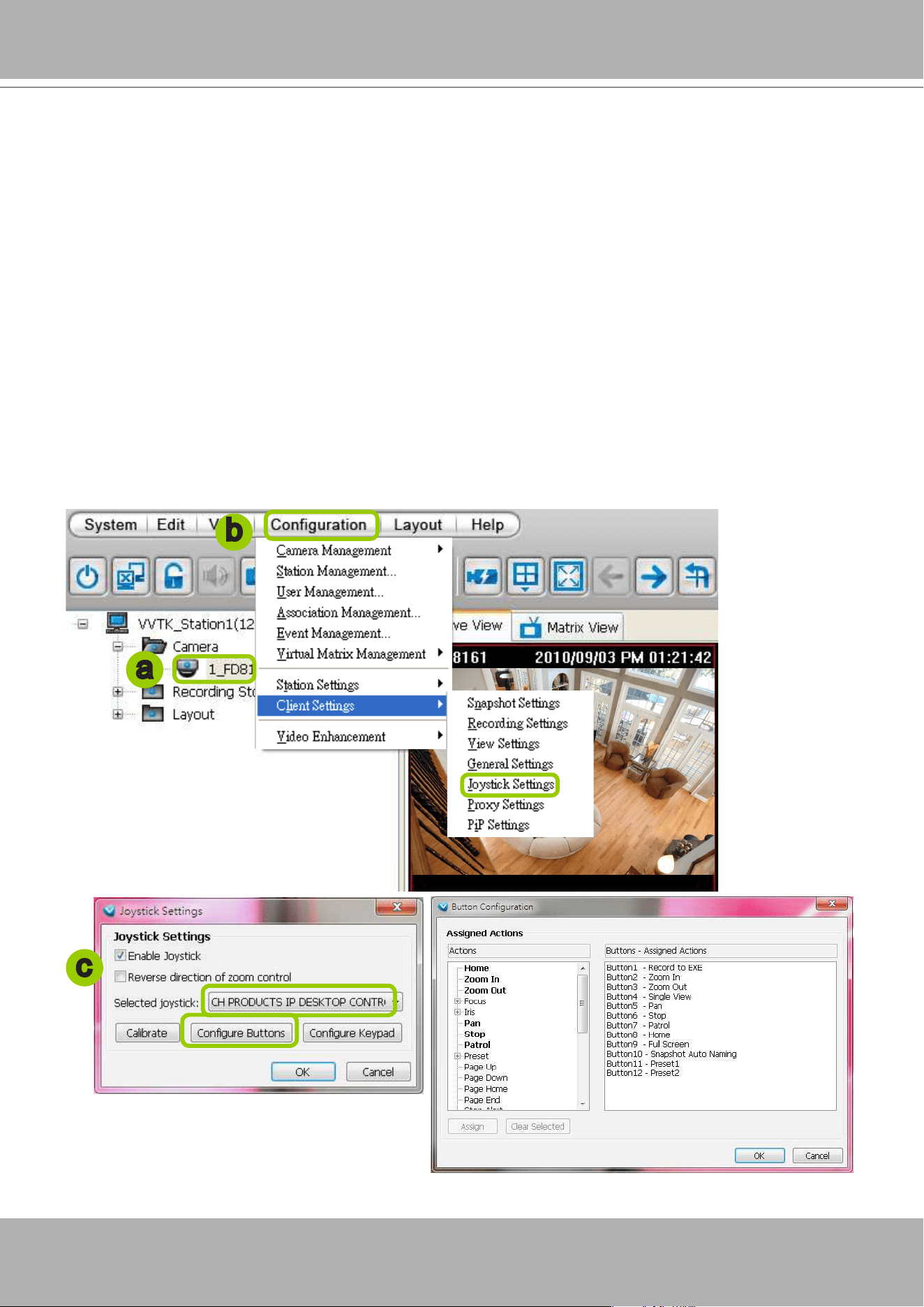
VIVOTEK - A Leading Provider of Multimedia Communication Solutions
User's Manual - 245
Joystick Settings
This section explains how to remote control connected network devices with a USB joystick. It’s
easy to install and congure via the USB interface.
Enable Joystick
Connect to the USB plug of the joystick to a USB port on your computer. Supported by the plug-in in the
main page (Microsoft’s DirectX), once the plug-in in the main page is loaded, it will automatically detect if
there is any joystick on the computer. The joystick should work properly without installing any other driver
or software.
Then you can begin to congure the joystick settings of connected devices. Please follow the instruction
below to enable joystick settings.
a. Select the target device from the hierarchical management tree.
b. Click
Conguration > Client Settings > Joystick Settings
on the menu bar to open the
Joystick
Settings
window. If your joystick is working properly, it will be displayed on the drop-down list.
c. Select the joystick you want to congure. Check
Enable Joystick
, then click
Congure Buttons
to
open Buttons conguration window.
a
b
c
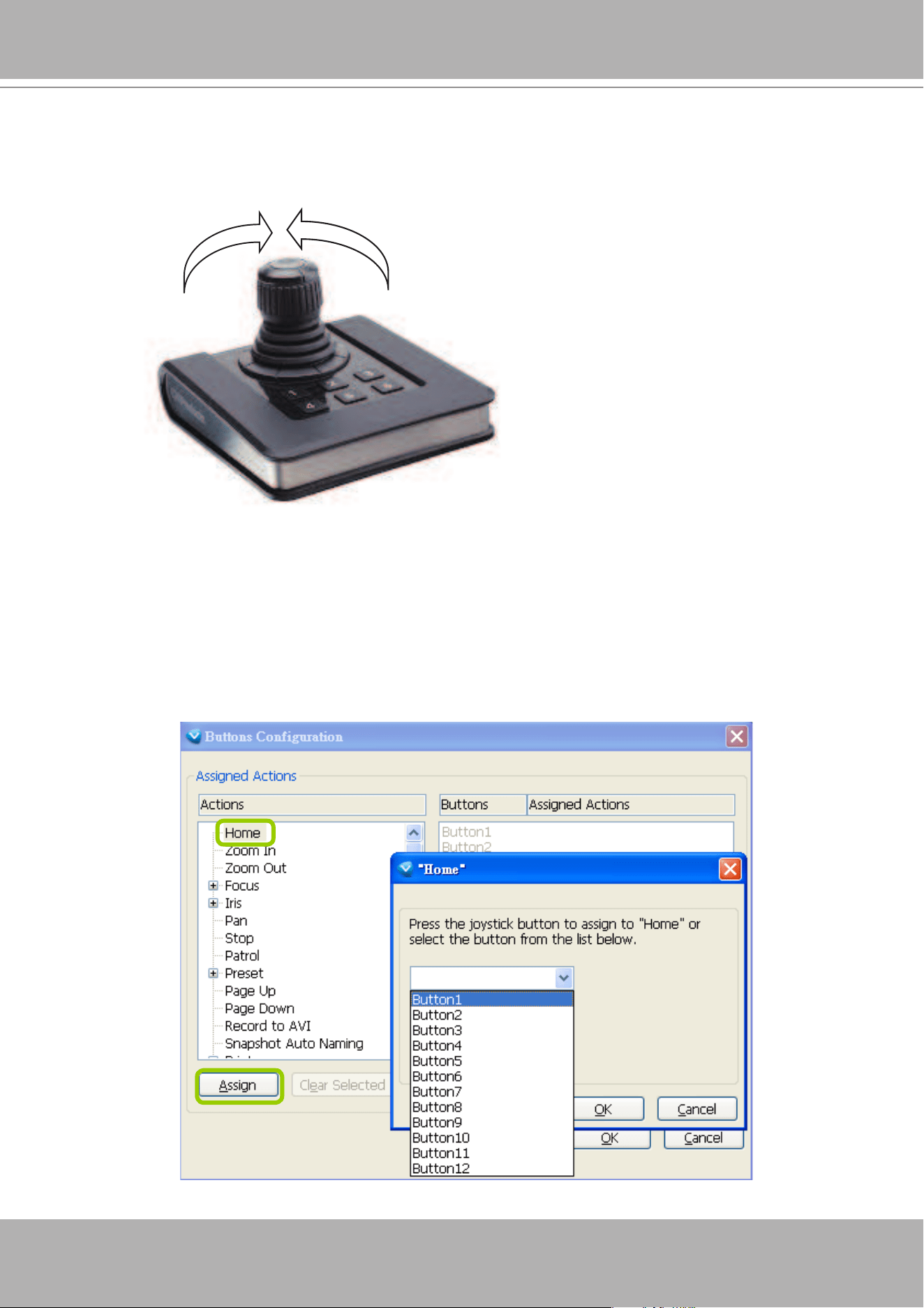
VIVOTEK - A Leading Provider of Multimedia Communication Solutions
246 - User's Manual
Buttons Conguration
In Button Conguration window, the left column shows the actions you can assign, and the right column
shows the functional buttons and assigned actions. The number of buttons may differ from different
joysticks.
Please follow the steps below to congure your joystick buttons:
a. Choosing one of the actions and click
Assign
will pop up a dialog. Then you can assign this action to
a button by pressing the joystick button or select it from the drop-down list.
For example: Assign
Home
(move to home position) to Button 1.
Reverse direction of zoom control
Due to different designs in joystick zoom wheel, you can select this checkbox to reverse the zoom in/out
directions.
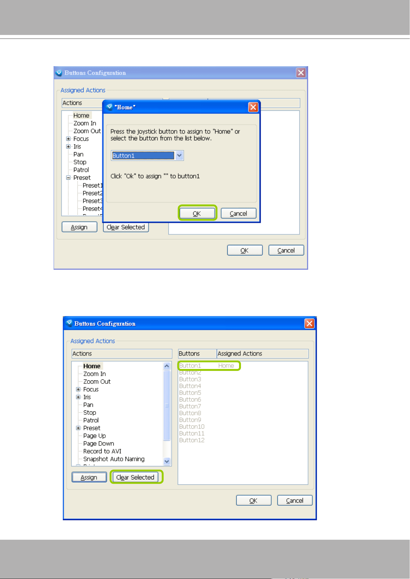
VIVOTEK - A Leading Provider of Multimedia Communication Solutions
User's Manual - 247
b. Click
OK
to conrm the conguration.
c.
The Assigned Action will appear beside Button 1 in the right column as shown in the following diagram.
Note that a button can only be assigned with an action. If you want to modify the settings, select the
action on the list and click
Clear Selected
.
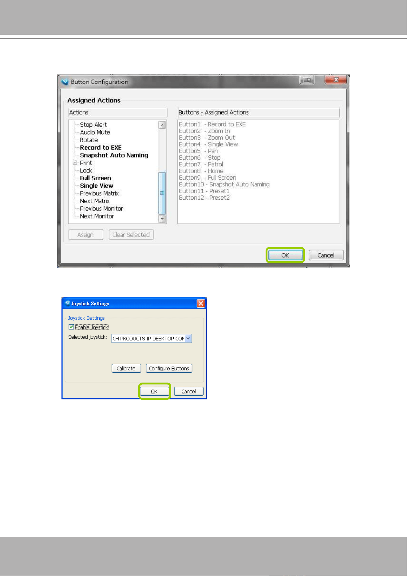
VIVOTEK - A Leading Provider of Multimedia Communication Solutions
248 - User's Manual
d. If you want to assign additional actions, repeat step a.~c. When all settings are complete, click
OK
t
o save the settings or click
Cancel
to discard the settings. You may also assign buttons to jump around
matrix screens.
e. Click
OK
to
save the settings or click
Cancel
to discard the settings.
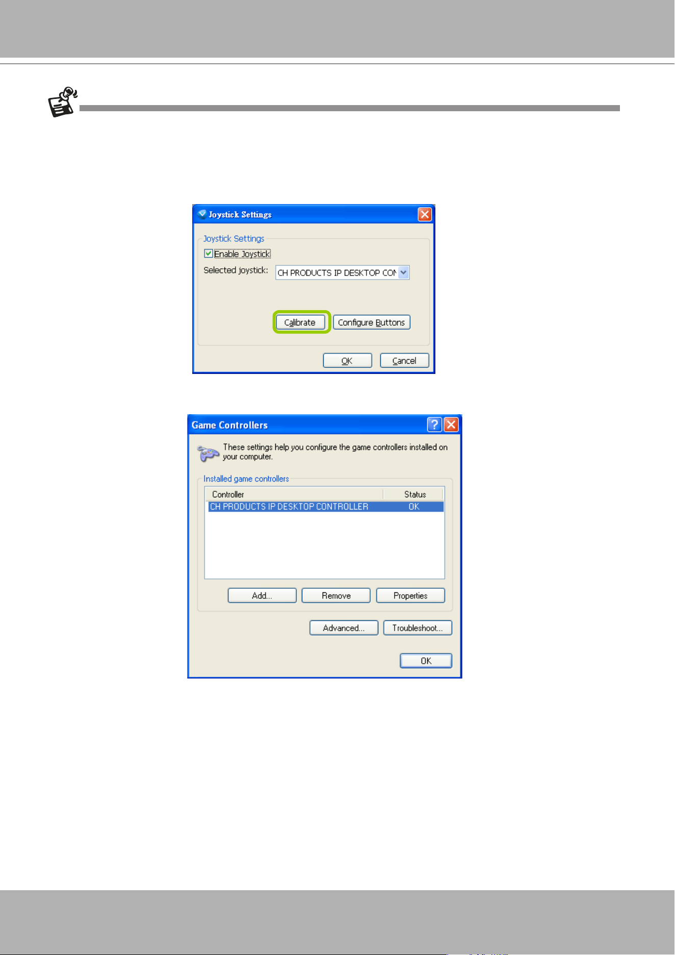
VIVOTEK - A Leading Provider of Multimedia Communication Solutions
User's Manual - 249
If you want to assign Preset actions to your joystick, the preset locations should be set up in advance.
If your joystick is not working properly, it may need to be calibrated. Click
Calibrate
to open the Game Controllers
window located in the MS Windows control panel
and follow the instructions for trouble shooting. For more
information, please refer to the MS Windows help les for details.
The joystick will appear in the Game Controllers list in the Windows Control Panel on your computer. If you want
to check out your device, go to the following page: Open Start > Control Panel > Game Controllers.
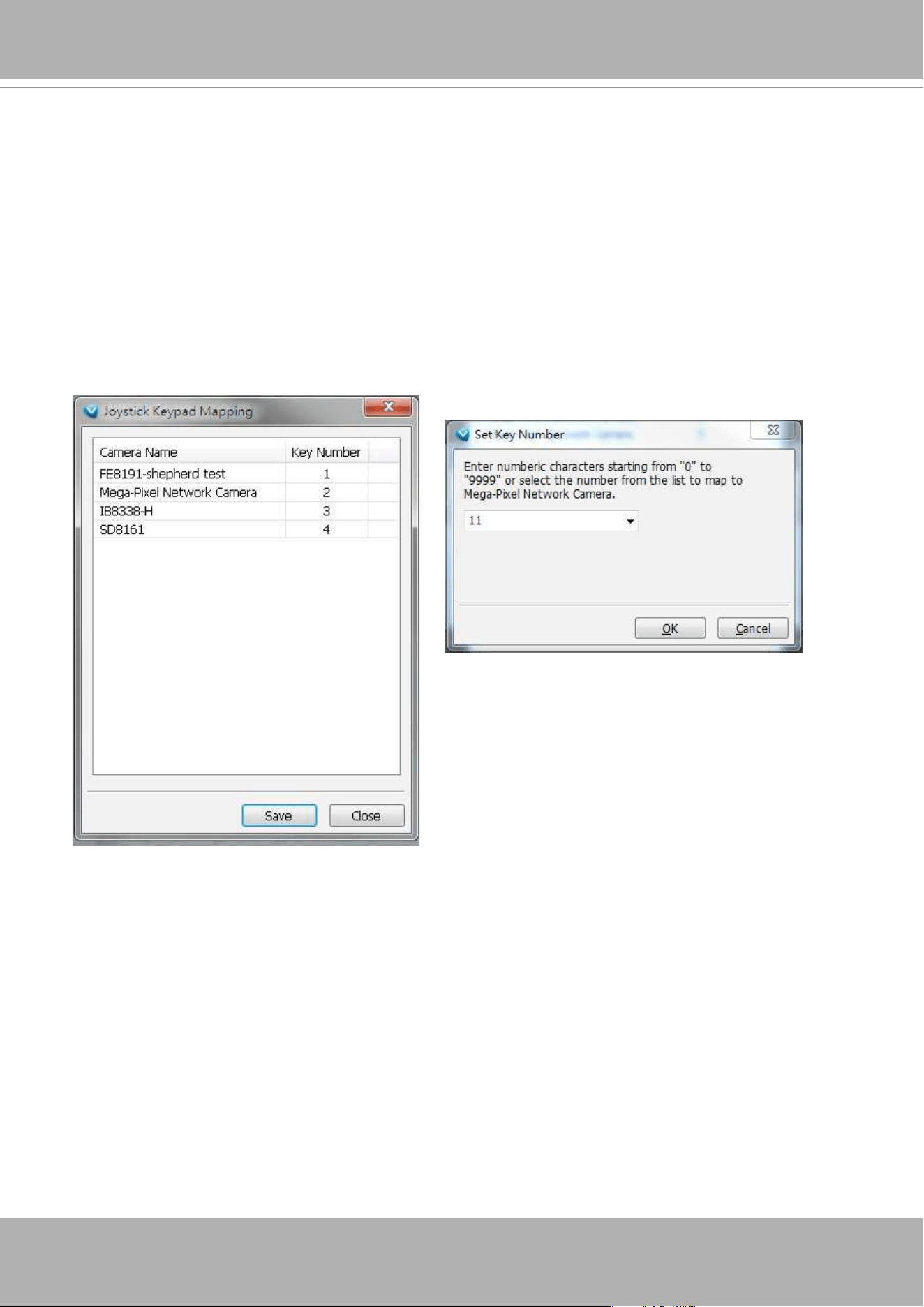
VIVOTEK - A Leading Provider of Multimedia Communication Solutions
250 - User's Manual
Congure keypad
For joysticks that come with a keypad, you can use the combination of a number assigned to a camera
and the Enter key on keypad to quickly move to the camera’s current view. The current view will be
displayed in a single view. To congure the number representative of each camera, double-click to open
a conguration window. The number used for quick switch must be mapped to an existing channel.
Also note the following:
1. The keypad key representative can be a 4-digit numeric combination.
2. If a number key is pressed without pressing the Enter key within 3 seconds, the command is cancelled.
3. You should have at least ONE EMPTY view cell.
4. A Rotation operation will be halted when using the keypad quick switch function.
5. This quick switch function does not take effect on the cameras managed by VAST substations.
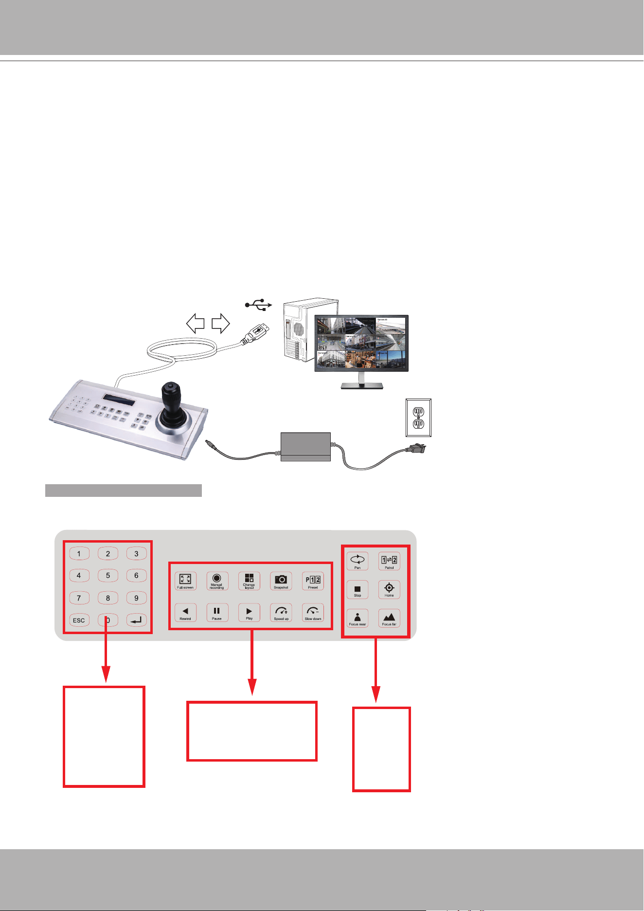
VIVOTEK - A Leading Provider of Multimedia Communication Solutions
User's Manual - 251
Joystick Settings - Using VIVOTEK's AJ-001 & AJ-002
The AJ-001 and AJ-002 joysticks come with some defaults working with a VAST server.
• Channel quick switch: Enter 1 to 4 numbers and press “Enter” on the keypad to bring the channel
into a full view. For example, enter 0010 and press Enter, CH 10 camera view will prompt on screen.
Note that the number keys and Enter must be pressed within 3 seconds.
• Currently, this function does not apply to cameras managed by sub-stations.
Camera 01
Camera 02
Camera 03
Camera 04
Camera 06
Camera 05
Camera 07
Camera 08
Camera 09
X2
VAST
12V DC
Following are the conditions for making the connection:
1. The joystick can either be powered by a DC 12V adaptor or via the USB. If powered by USB, plug the
USB cable twice to the USB port to enable USB power.
2. Connect the included USB cable between the USB ports on the joystick and a VAST server.
KEYPAD DEFINITION
1 2
3 4
5 6
8
28
21 22
24 25
23 7
26 27
9 10
12 13
11
14
15 16
18 19
17
20
Below is the keypad numbering sequence:
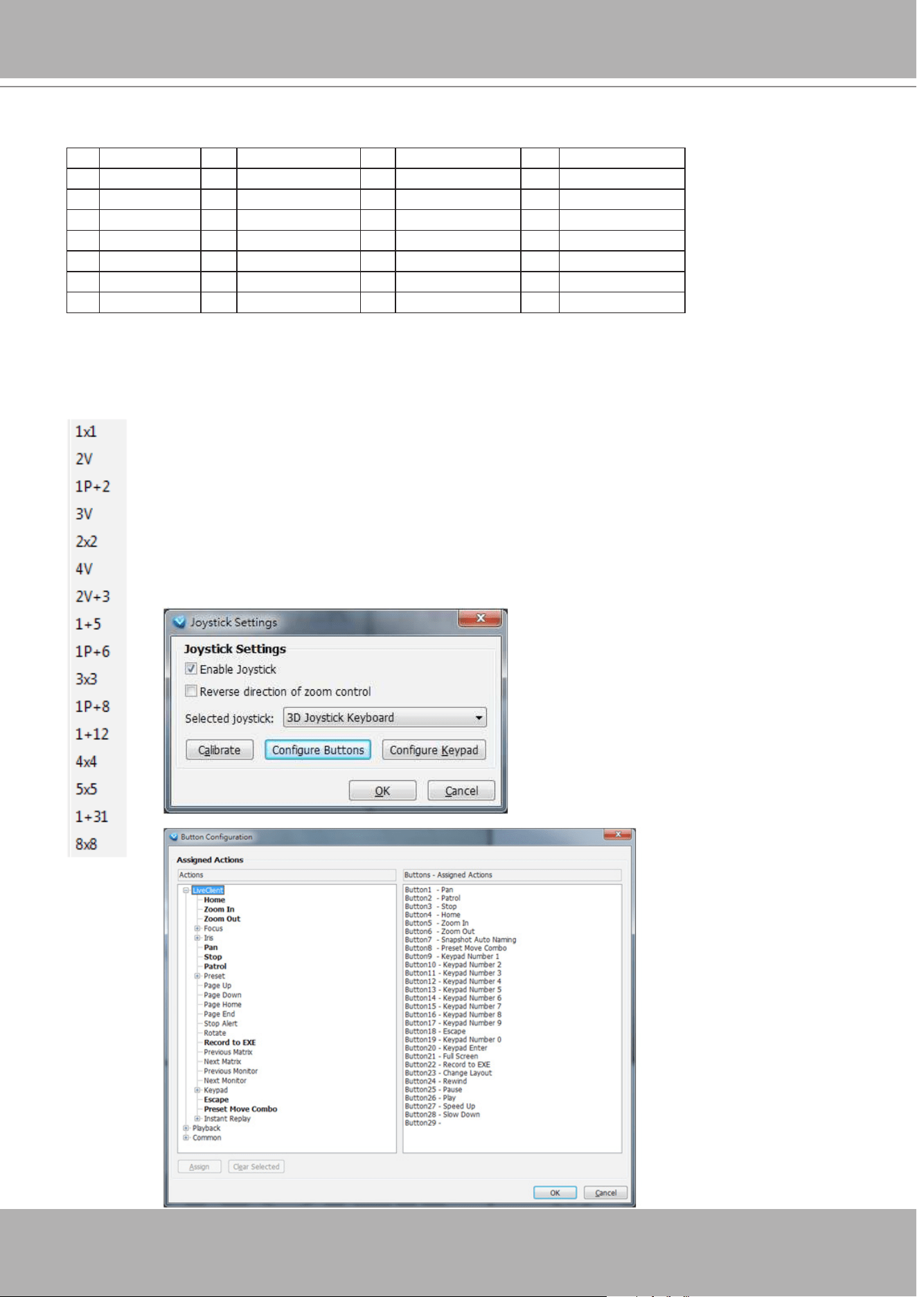
VIVOTEK - A Leading Provider of Multimedia Communication Solutions
252 - User's Manual
Since VAST rev. 1.13, the following keypad functions will be available as the defaults for the joystick.
1 Pan 9 #1 17 #9 25 Pause
2 Patrol 10 #2 18 Cancel/Clear/Esc 26 Play
3 Stop 11 #3 19 #0 27 Speed Up
4 Home 12 #4 20 Enter 28 Speed Down
5 Zoom in 13 #5 21 Full Screen
6 Zoom out 14 #6 22 Manual recording
7 Snapshot 15 #7 23 Change Layout
8 Preset 16 #8 24 Rewind
Pressing the layout button changes the current view cell layout. Press to change the layout
from top to bottom as shown on the left.
Use the combination of "Preset Move Combo" (button 8) + number keys + Enter.
For example button 8 + 1 + 0 + Enter -> Preset #10.
You can see the default denitions for the keypad in the Joystick conguration windows.
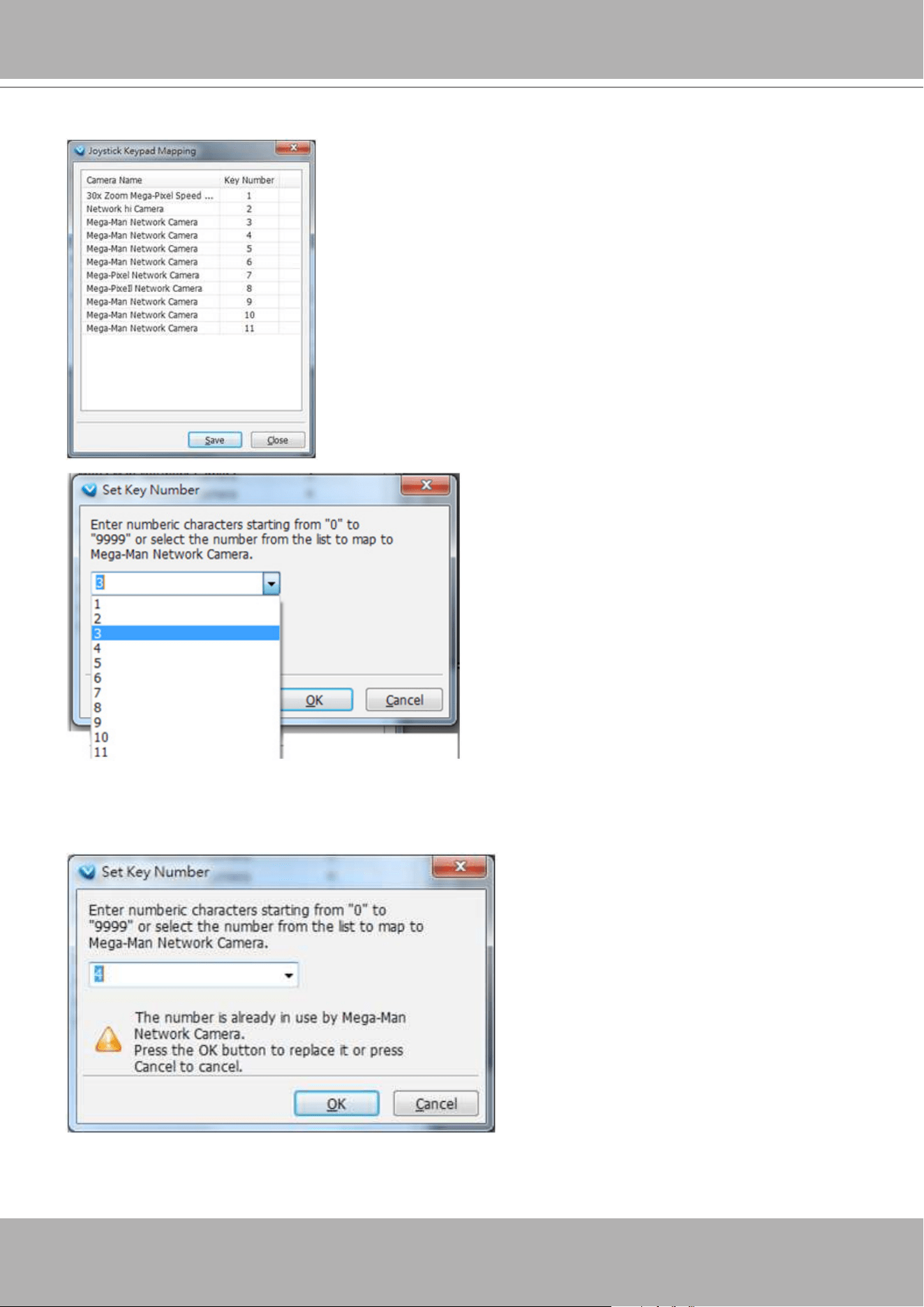
VIVOTEK - A Leading Provider of Multimedia Communication Solutions
User's Manual - 253
The below message shows a mapping table ID conict.
If you should need to change the mapping table, use the Keypad Mapping function.
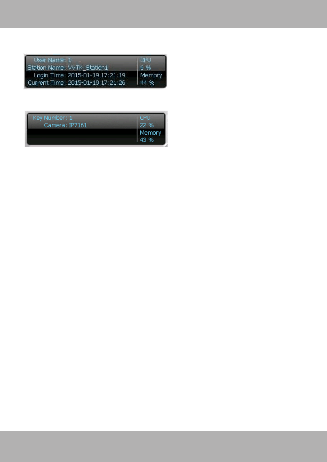
VIVOTEK - A Leading Provider of Multimedia Communication Solutions
254 - User's Manual
Below is the normal server status information.
The capture below shows the status when using a keypad to quickly switch to a camera's live view.
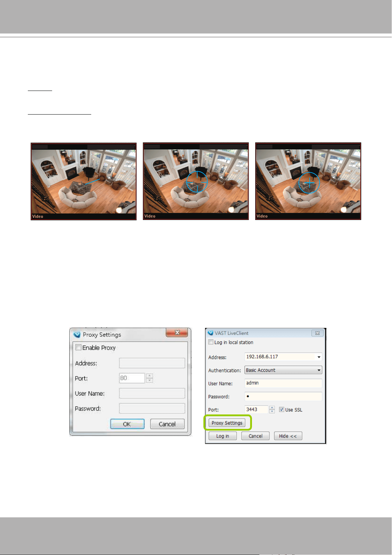
VIVOTEK - A Leading Provider of Multimedia Communication Solutions
User's Manual - 255
PTZ/ E-PTZ Function
In addition to using the PTZ control panel, you may also control the rotation handle of the joystick to
remote control a PTZ/ E-PTZ network camera with ease.
Pan/Tilt: Move the rotation handle of the joystick; you can pan the camera to the desire position. There
will be blue line displaying the moving direction in the center of the video image as the diagram 1 below.
Zoom in/Zoom out: Shift the rotation handle clockwise to zoom in the camera on an image or go
counterclockwise to zoom out the camera on an image. There will be a circle and four vectors in the
center of the video image as the diagram 2, 3 below.
Proxy Settings
In this section, you can enable, modify, or cancel
Proxy Settings
for client if your VAST Server
is under a proxy. If you change the proxy settings, please ll in the new value next time you login
the LiveClient next time.
Zoom in
(Turn the rotating handle clockwise)
Zoom out
(Turn the rotating handle counter-clockwise)
Pan/Tilt
(Move the rotating handle back and forth)
FD8161
FD8161 FD81612010/09/03 PM 03:56:17
2010/09/03 PM 03:56:17
2010/09/03 PM 03:56:17
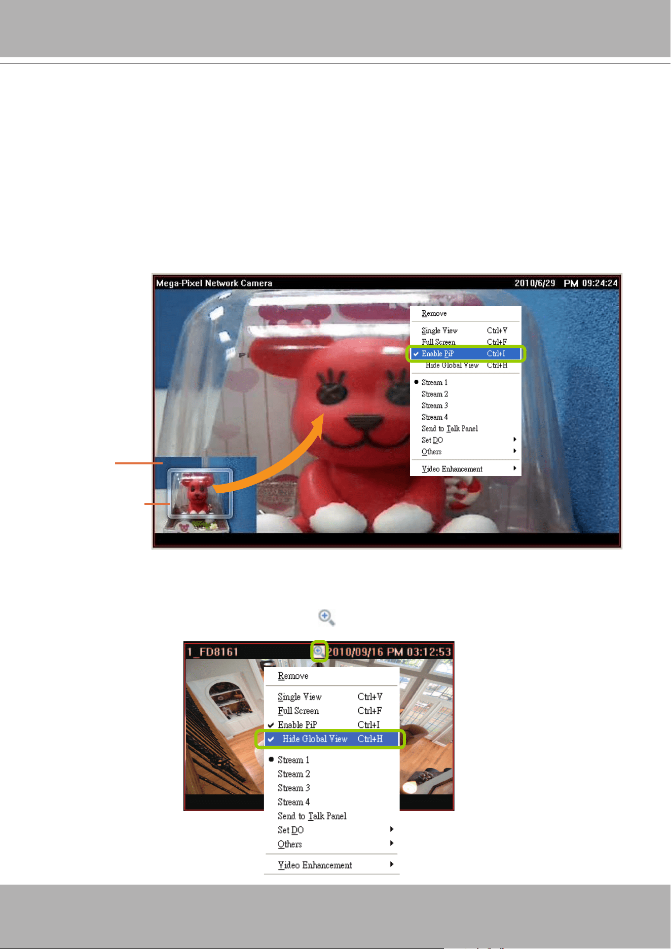
VIVOTEK - A Leading Provider of Multimedia Communication Solutions
256 - User's Manual
How to Use PiP (Picture-in-Picture)
PiP (Picture-in-Picture) is an intuitive function for user to simultaneously view a Global View and
ROI (Region of Interest) for live monitoring. The digital zoom in function can only focus on the
interested area and represent the details of megapixel video. Moreover, the multi-touch mode is
a very user-friendly interface for digital zoom in.
Enable PiP
Right-click
the video cell and select
Enable PiP
. If you want to disable PiP, click the option again to
uncheck it. After you enable the PiP function, a movable global view window and a ROI frame will be
displayed as shown below.
Global View
The global view is the original view with the size scaled down to 160x120. It is movable and you can drag
it anywhere in the live view window. If you want to hide the global view,
right-click
the video cell and
select
Hide Global View
from the menu. An icon will appear on top of the live view window.
Region of Interest
(ROI)
Global View
Digital Zoom In
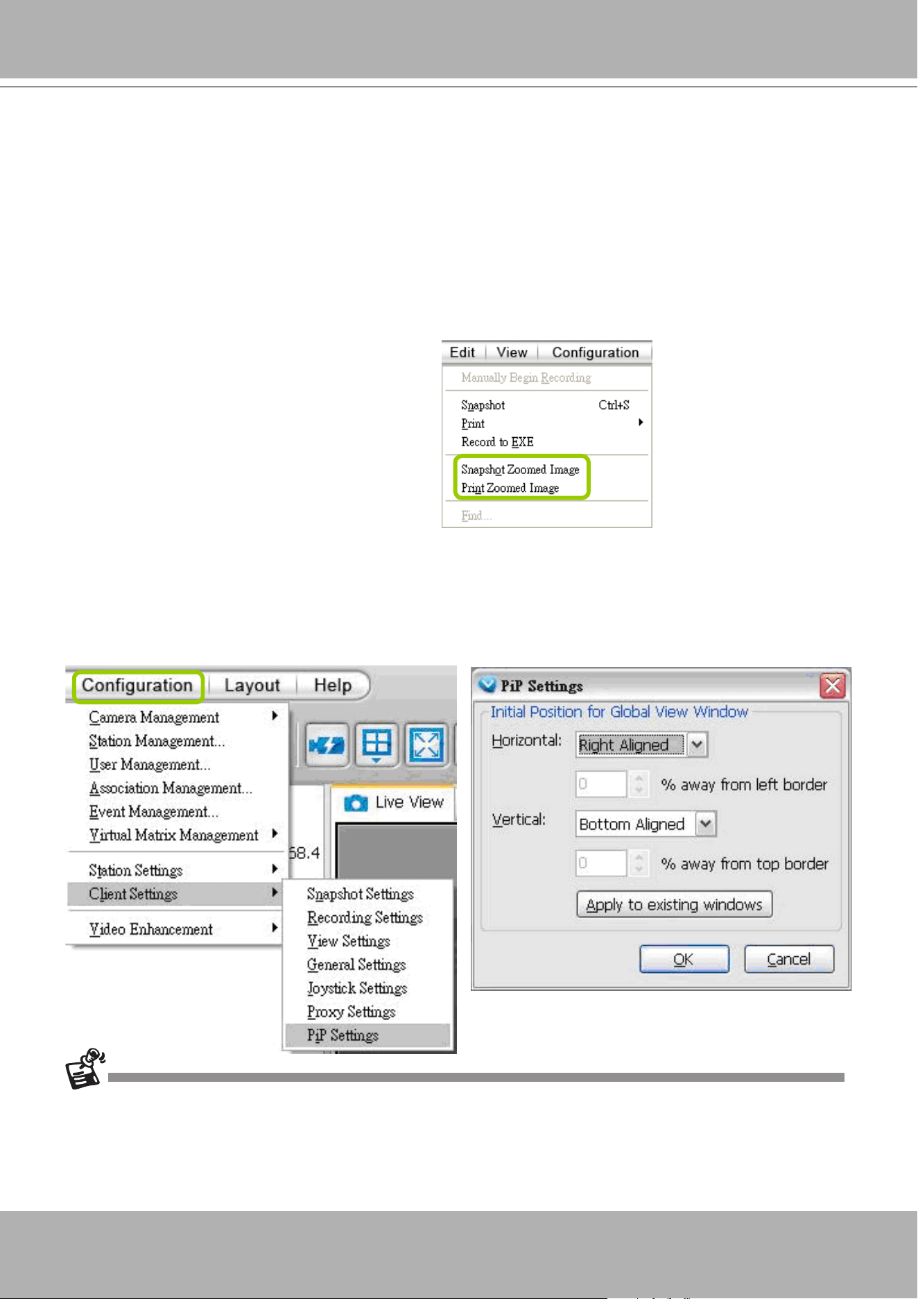
VIVOTEK - A Leading Provider of Multimedia Communication Solutions
User's Manual - 257
ROI (Region of Interest)
The ROI frame is capable of being resized and dragged in any direction upon the global view window as
e-PTZ function.
Digital Zoom In
Through digital zoom in, the live view window will be lled with the zoomed in ROI image. The maximum
magnication of the ROI frame is 16x zooming. The zoomed in area will change as the ROI frame is
dragged and resized. You can also easily zoom in and zoom out the ROI frame by rolling the mouse back
and force.
Snapshot & Print Zoomed In Image
You can snapshot and print the zoomed in image.
PiP Settings
The PiP Settings is for you to adjust the initial position of the global view window.
Click
Conguration > Client Settings > PiP Settings
to open the window.
On top of it, you may choose
the horizontal position with left / middle / right side of the live view window, or you can customize the
percentage of space distance from the border of the live view window as an option. It is also fully applied
for vertical position with top / middle / bottom side of the live view window. When it’s done, you may click
on
Apply to existing windows
to enable the settings.
If the position of ROI and global view will be saved and applied for the next open. It will be removed when the live
view cell is removed.
The PiP function is also applied in VAST Playback.
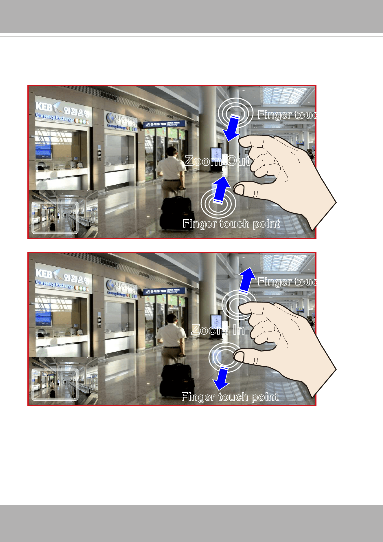
VIVOTEK - A Leading Provider of Multimedia Communication Solutions
258 - User's Manual
Multi-touch Mode
VAST also supports advanced multi-touch mode for PiP. You can easily zoom in or zoom out the image
by touching the multi-touch monitor with two ngers.
Zoom Out
Finger touch point
Finger touch point
Zoom In
Finger touch point
Finger touch point
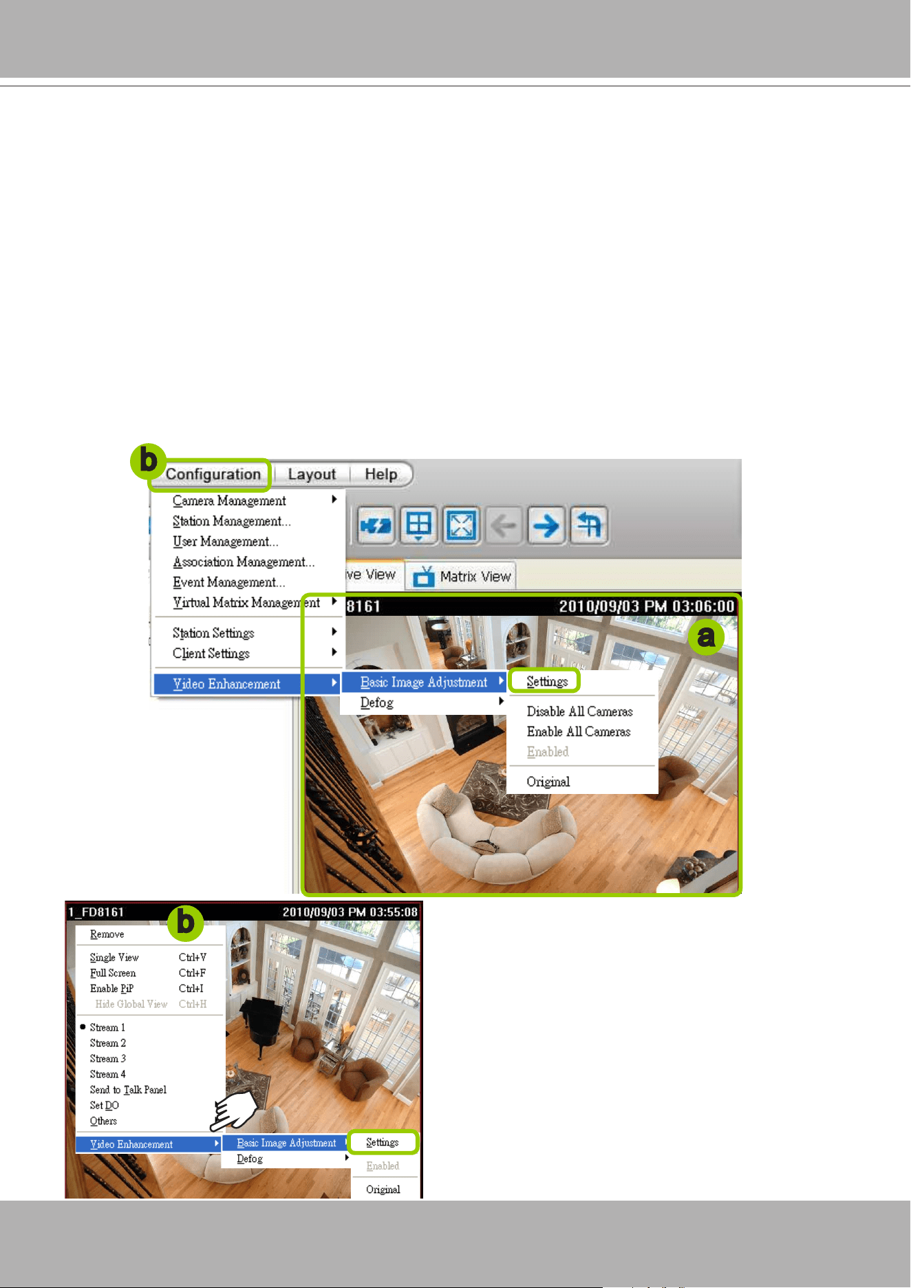
VIVOTEK - A Leading Provider of Multimedia Communication Solutions
User's Manual - 259
How to Congure Video Enhancement
The LiveClient allows you to enable post-image enhancement and defog for video live view.
Basic Image Adjustment
This function allows you to configure basic image adjustment including Brightness, Contrast,
Saturation, and Hue.
Please follow the steps below to set a prole for post-image adjustment settings:
a. Select the target video cell.
b. Click
Configuration > Video Enhancement > Basic Image Adjustment > Settings
on the menu
bar to open the
Profile Settings
window. (Or you can
right-click
the video cell and select
Video
Enhancement > Basic Image Adjustment > Settings
from the popup menu.)
a
b
b
c. Adjust the values of Brightness, Contrast, Satura-Brightness, Contrast, Satura-
tion, and Hue. You can preview the image from the
window on the right. A “VE (Video Enhancement)”
text string will appear at the bottom right of the
preview window.
d. When completed, click
Save as Prole
and enter
a name for the new prole.
e. The new prole will be displayed on the drop-down
list. This prole can be applied to all video cells.
f. If you decide to apply the selected profile to the
target video cell immediately, click the
OK
button.
Otherwise, click
Cancel
to close the window.
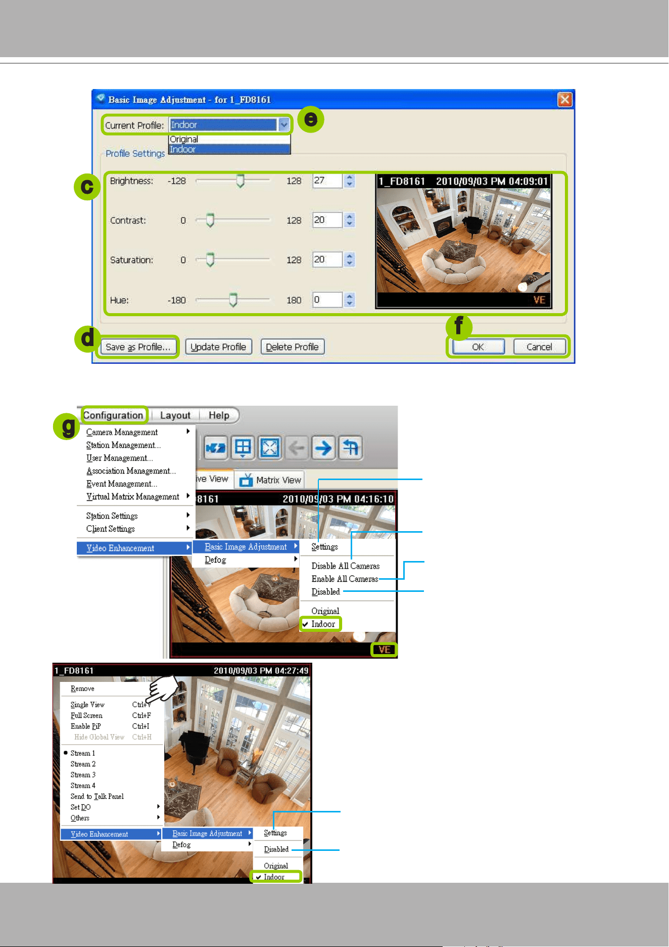
VIVOTEK - A Leading Provider of Multimedia Communication Solutions
260 - User's Manual
g. Back to the main page, a “VE” text string will also appear at the bottom right of the video cell and the
new prole will also appear and be selected on the popup menu as shown below.
c
e
f
d
g
Click to create a new prole, edit
or delete a customized prole
Click to disable VE on all linked
devices
Click to enable VE on all linked
devices
Click to enable/disable VE on the
target video cell
Click to create a new prole, edit or delete a
prole
Click to enable/disable VE on the target video
cell
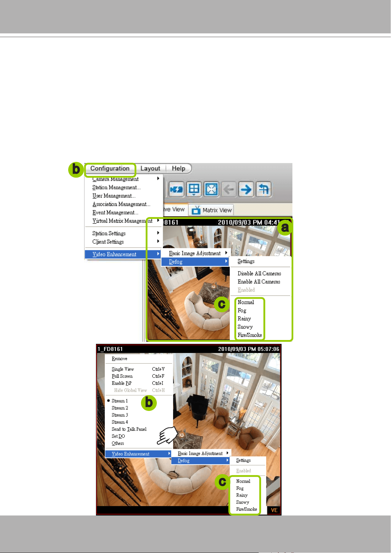
VIVOTEK - A Leading Provider of Multimedia Communication Solutions
User's Manual - 261
Defog
This function allows you to congure post-image defog.
Apply a Preset Defog Prole
Please follow the steps below to set post-image defog settings:
a. Select the target video cell.
b. Click
Conguration > Video Enhancement > Defog
or
right-click
the video cell and select
Video
Enhancement > Defog
.
c. There are some preset proles for you to apply to the target video cell. You can select one from the list
accoding to the environment.
a
b
b
c
c
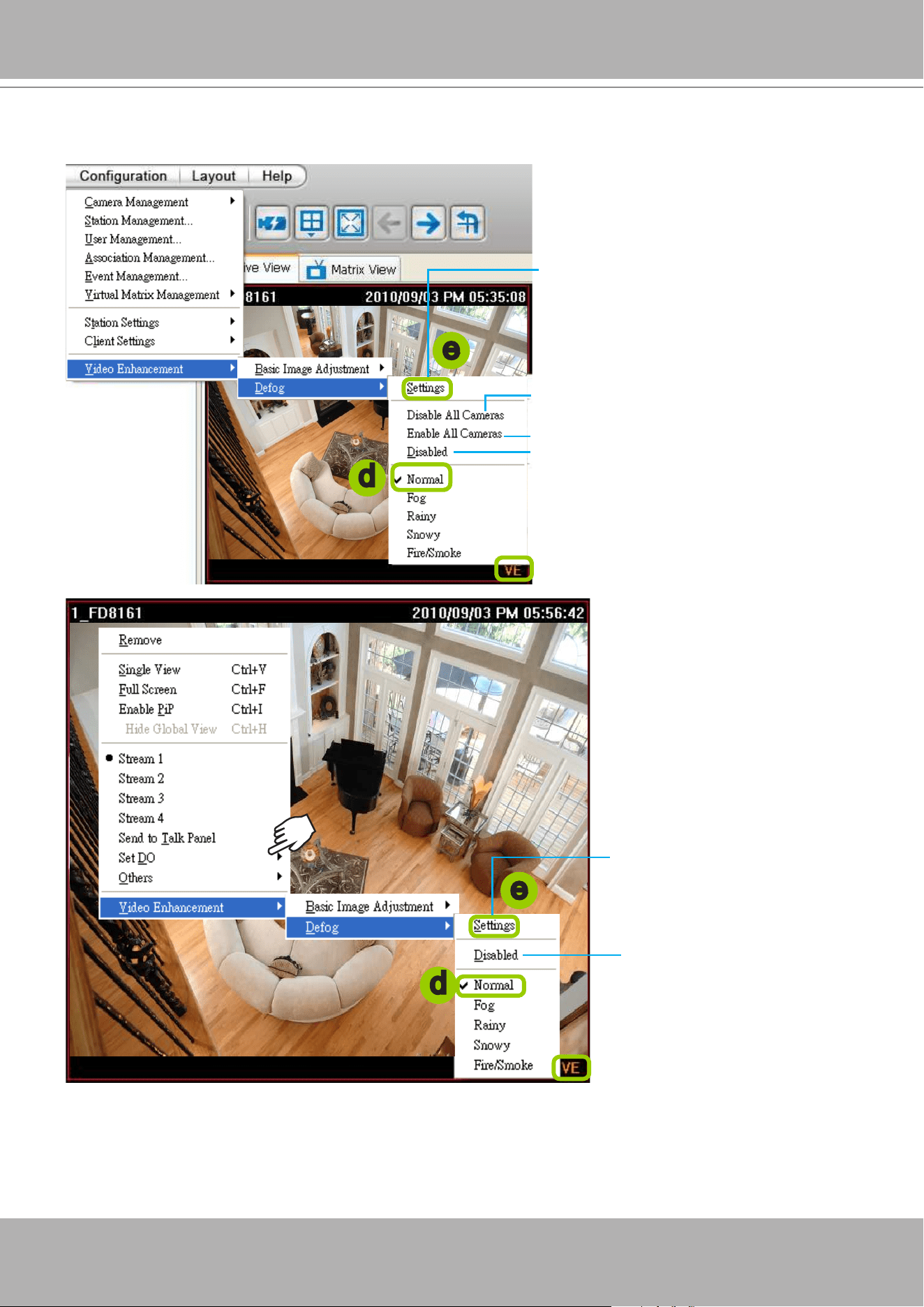
VIVOTEK - A Leading Provider of Multimedia Communication Solutions
262 - User's Manual
d. The string of the selected prole will be selected as shown below. A “VE” text string will also appear at
the bottom right of the video cell.
Create a New Defog Prole
e. Click
Settings
on the popup menu to open the
Prole Settings
window.
d
d
Click to create a new prole, edit or
delete a customized prole
Click to disable VE on all linked devices
Click to enable VE on all linked devices
Click to enable/disable VE on the target
video cell
e
e
Click to enable/disable VE
on the target video cell
Click to create a new prole,
edit or delete a prole
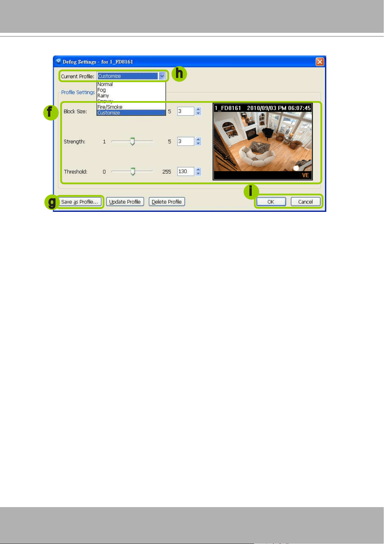
VIVOTEK - A Leading Provider of Multimedia Communication Solutions
User's Manual - 263
f. Adjust the values of Block Size, Strength, and Threshold. You can preview the image from the right
window. A “VE (Video Enhancement)” text string will also appear at the bottom right of the preview
window.
Block Size: Brush diameter from thick to thin (Value 1~5)
Strength: Brush stroke from soft to strong (Value 1~5)
Threshold: Brush pixel from loose to dense (Value 0~225)
g. When completed, click
Save as Prole
and enter a name for the new prole.
h. The new prole will be displayed on the drop-down list. This prole can be applied to all video cells.
i. If you decide to apply the selected prole to the target video cell immediately, click the
OK
button. Oth-
erwise, click
Cancel
to close the window.
f
h
i
g
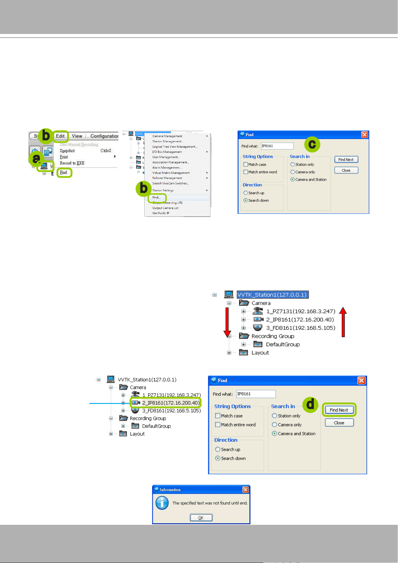
VIVOTEK - A Leading Provider of Multimedia Communication Solutions
264 - User's Manual
How to Search for a Device on the Hierarchical Management Tree
This function allows you to conveniently search for an inserted device, which is useful when
many devices have been inserted.
Please follow the steps below to nd a device on the camera list:
a. Click the station on the hierarchical management tree.
b. Click
Edit > Find
on the menu bar (or
right-click
the station and click
Find
).
c.
The
Find
window will pop up for you to set your search criteria.
Find what: Enter a string in the blank. The string can be the full or partial name of the device you want
to search for.
String Options:
Match case
represents that the search results should be identical to the string in
lower-case or upper-case letters, the string can be part of a word.
Match whole word
means that
the search results should be identical to the string for every character, and that the string should be a
complete word or phrase. If you select both options, the search results should conform to all criteria
listed above.
Direction: Select
search up
or
search down
.
Search in: Select
search in station or camera
.
d. Click
Find Next
, the seaching result will be marked as shown below.
e. If there is nothing found in the camera list, a message will pop up as shown below:
Search up
Search down
a
b
c
Search results
d
b
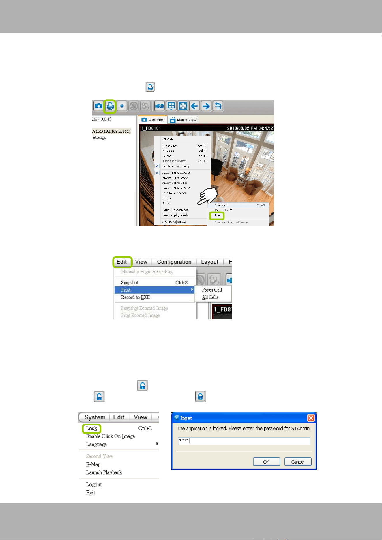
VIVOTEK - A Leading Provider of Multimedia Communication Solutions
User's Manual - 265
How to Print a Video Image
There are two ways to print out an image of live video:
1. Select a video cell, then click
Print
on the quick access bar, or
right-click
the video cell and select
Print
from the popup menu. A Print window will pop up for you to choose the printer.
2. You can also click
Edit > Print
to print out an image from a video.
Focus Cell: Print out an image of the target video.
All Cells: Print out an image with all video cells in the monitoring window.
How to Lock LiveClient for Security Concerns
If you are away from your computer, for security reasons, we suggest you lock the program.
When LiveClient is locked, the user must ll in the correct password to unlock and access the
program again.
To lock LiveClient, click
Unlock
on the quick access bar or click
System > Lock
on the system
menu. The
Unlock
icon will then turn into
Lock
.
To unlock LiveClient, fill in the correct password in the popup window.
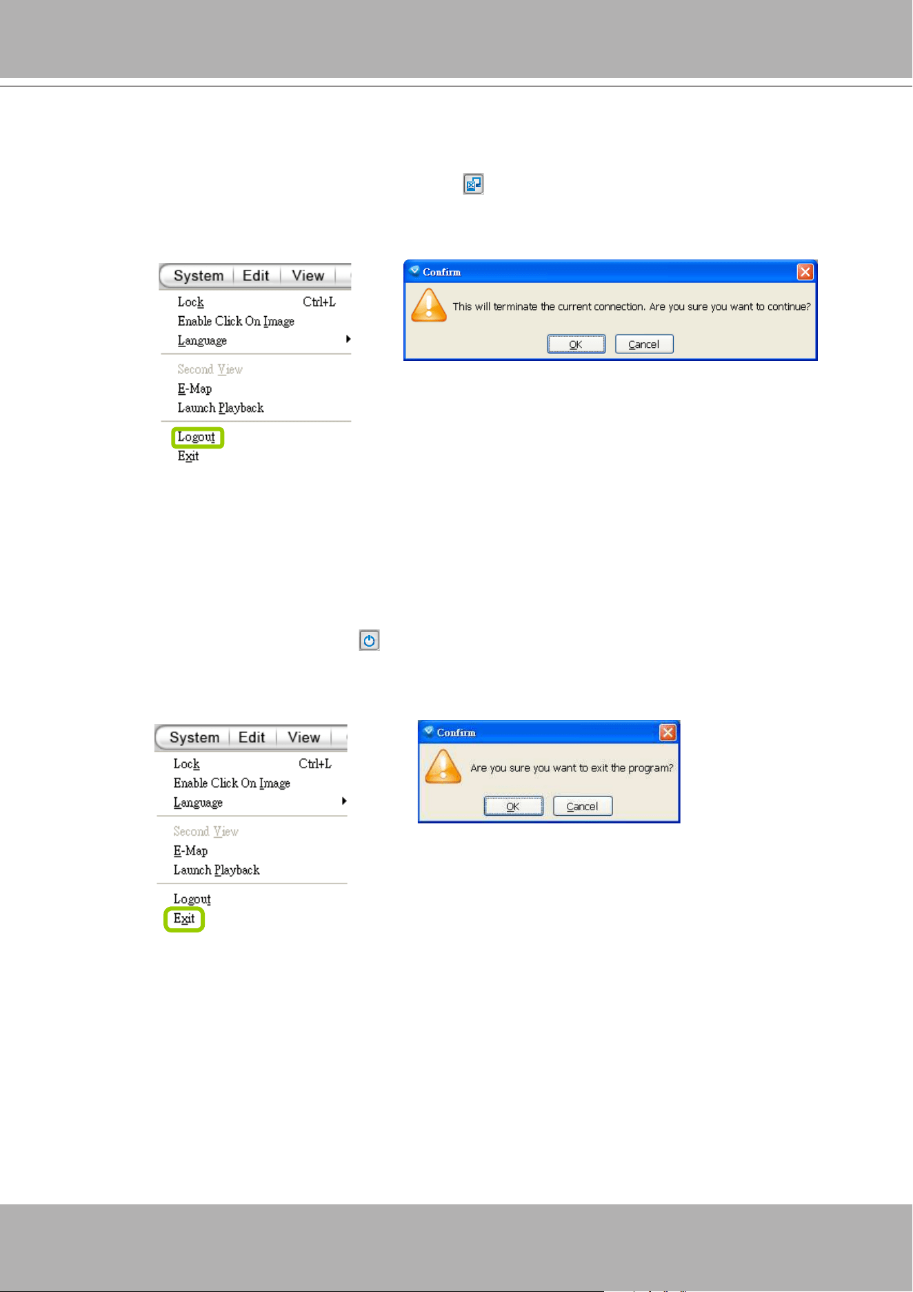
VIVOTEK - A Leading Provider of Multimedia Communication Solutions
266 - User's Manual
How to Log out from the VAST Server
To logout from the current server, click
Logout
on the quick access bar or click
System >
Logout
on the menu bar. A conrmation window will pop up. Click
OK
to conrm or
Cancel
to
return to the VAST LiveClient window.
How to Exit VAST LiveClient
To exit VAST LiveClient, click
Exit
on the quick access bar or click
System > Exit
on the
menu bar. A confirmation window will pop up. Click
OK
to confirm or
Cancel
to return to the
VAST LiveClient window. When you exit the program, your user account will be automatically
logged out from the current server.
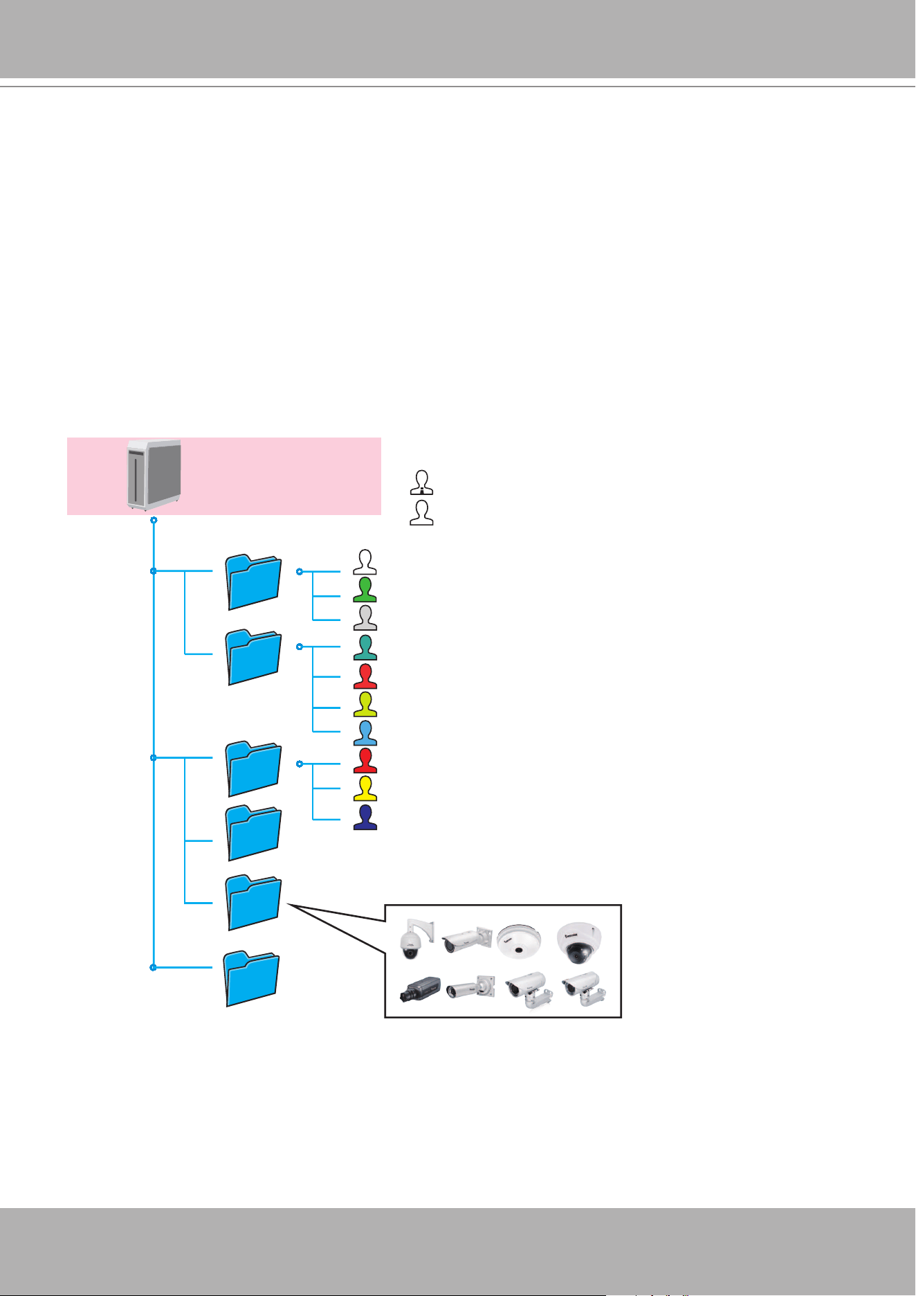
VIVOTEK - A Leading Provider of Multimedia Communication Solutions
User's Manual - 267
How to Congure a Logical Tree
A Logical Tree view is available since rev. 1.10 for both LiveClient and Playback. The Logical
Tree view allows you to re-dene the logical relationships between the real-world deployment
and the physical devices (cameras). For example, according to your deployments, you can
designate several cameras to be listed under a logical sub-directory named as "Building A," and
the other cameras into "Building B." In this way, you can re-arrange your cameras and devices
on a tree view that is geographically accurate.
In addition to this, the logical folders can also be used to create privilege groups for users with
different access rights. This enables an administrator to easily and exibly align user privileges
with his camera deployments.
(Root station)
VAST CMS Server
(Admin: all areas)
(Power users:
main building regions)
(Logical folders)
(Users:
Front door and drive lanes)
(Power users:
work area #1)
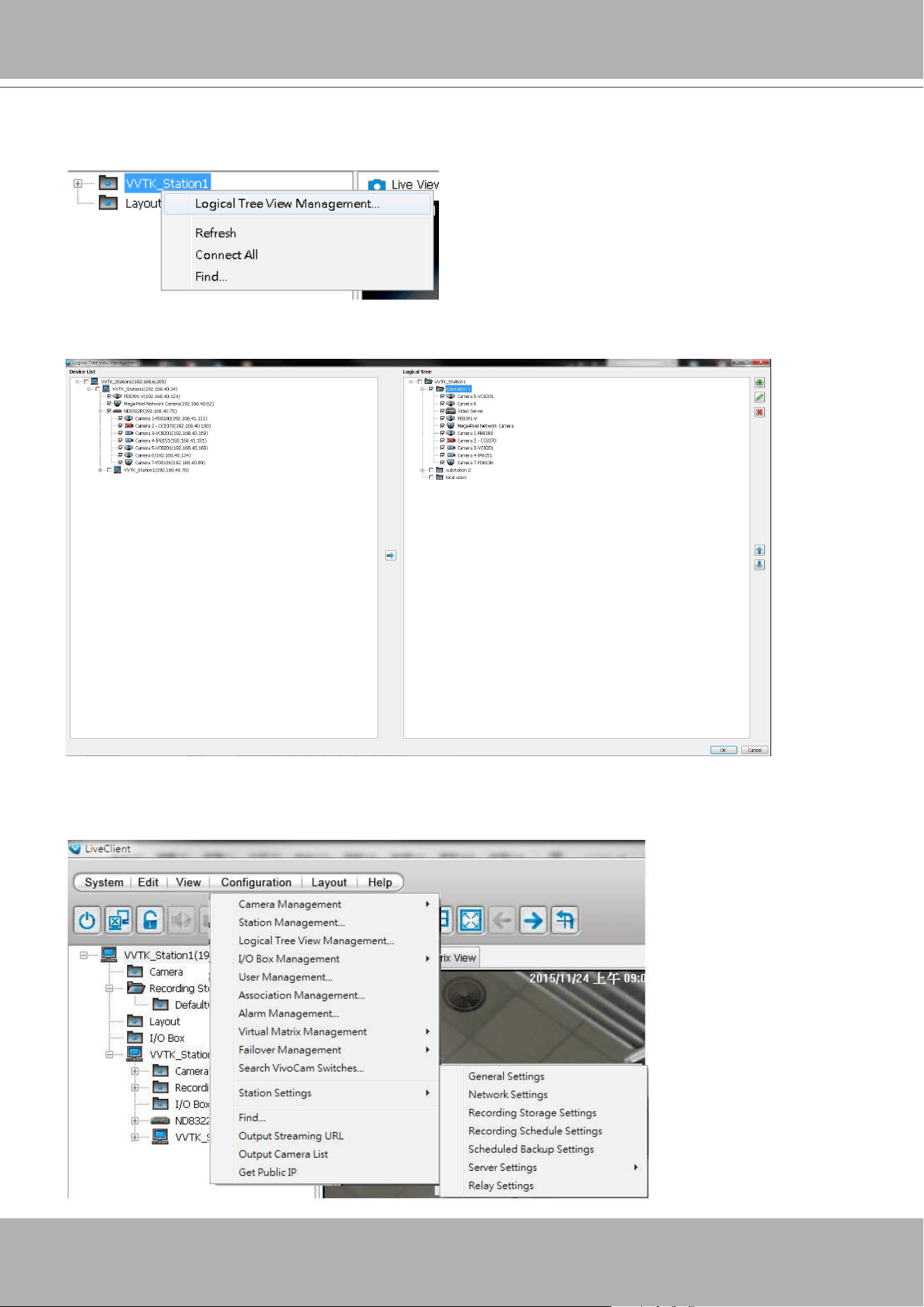
VIVOTEK - A Leading Provider of Multimedia Communication Solutions
268 - User's Manual
To congure a Logical Tree, either right-click on the Device list root entry (VVTK_Station1), or
visit the top menus through
Conguration
>
Logical Tree View management
.
You will then enter the
Logical Tree View
management window. Left click on the root directory,
and then right-click to display the
Add
command.
A Logical tree can also display and include the cameras from VAST substations. To enable
connection with substations, make sure the
Relay Settings
is enabled both on the VAST Root
and substations.
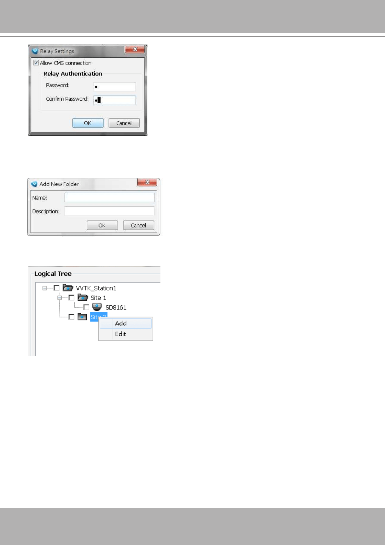
VIVOTEK - A Leading Provider of Multimedia Communication Solutions
User's Manual - 269
You can also create logical folders under sub-directories, e.g., a "Corridor" under "Building A."
Do this by selecting a sub-directory with a left-click and then right-click on it.
To create a logical folder, enter a name for the sub-directory. The name can be a geographical
indicator or whatever name your prefer; such as Building A, Site 1, etc. Add a short description.
Note that the root directory can not be edit.
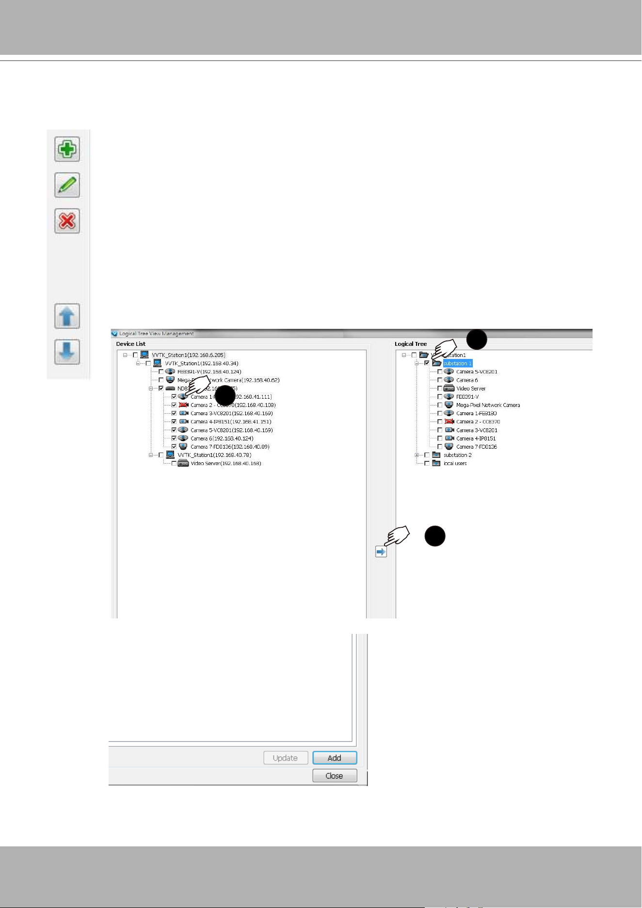
VIVOTEK - A Leading Provider of Multimedia Communication Solutions
270 - User's Manual
You may also left-click to select a sub-directory, and use the
Add
,
Edit
, and
Delete
buttons to
create, edit, or remove sub-directories. Use the arrow buttons to change the positions of sub-
directories or devices on the logical tree.
When done, click the
OK
button at the low right corner of the window.
Conguration changes will be preserved.
1
2
3
You should then insert cameras to a preferred directory:
1. Open the device tree to select camera. Left-click to select the checkboxes in
front of cameras.
2. Select the checkbox of a preferred sub-directory. Make sure the checkbox is
selected and the directory is highlighted.
Use the Sort and Find functions on the Device List on the left panel if it is hard to locate a
device.
3. Click the
Move
button in the middle of the screen.
Cameras will be listed under the target sub-directories.
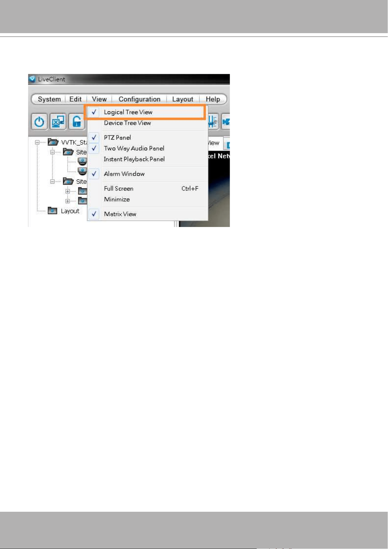
VIVOTEK - A Leading Provider of Multimedia Communication Solutions
User's Manual - 271
When done with the configuration, click the OK button, and select from the top menus
View
>
Logical Tree View
. The Logical Tree View will become the standard display for your VAST
conguration.
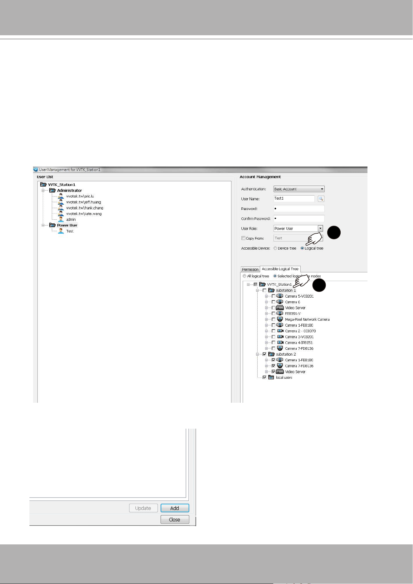
VIVOTEK - A Leading Provider of Multimedia Communication Solutions
272 - User's Manual
When done with the creation of logical folders, you can move to the
User Management
window. You can then dene users' access rights using the logical folders you created. For
example, you may let a user access a specic logical folder while forbidding him from the
others.
1
2
1. When you assign Accessible Devices for a user, select the
Logical tree
button on the
lower right.
2. Select the "
Selected logical tree nodes
" button. You can then select or deselect logical
folders to conne the accessible devices for a user.
Note that an administrator has access to all devices, and hence the selection is not
available for an administrator.
3. Click the
Add
button on the lower right.
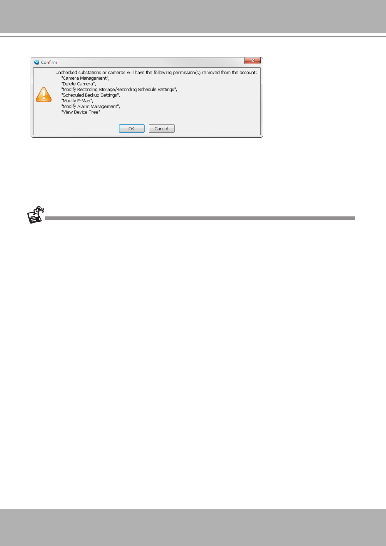
VIVOTEK - A Leading Provider of Multimedia Communication Solutions
User's Manual - 273
4. The User account information will prompt. Click
OK
to proceed.
• The Refresh, Camera Settings, Output Streaming URL, Send to Talk Panel commands are
available for cameras listed in the Logical Tree View.
• The DI/DO, Recording Storage, and I/O Box are not available on a Logical Tree View.
• The root directory (default VVTK_Station1) can not edited or removed.
• A camera can be added to different sub-directories; however, it can not be added twice into
the same sub-directory.
• A camera managed by a sub-station can be added into the Logical Tree.
• The Logical Tree View can not be edited through a web console with the VAST server.
• Cameras added to the VAST conguration will not be automatically added to the Logical Tree
View.
• By default, only the administrator and power user are authorized to configure the Logical
Tree View.
5. You can repeat the above steps to create more user accounts using the limited access
conguration via the use of logical folders.
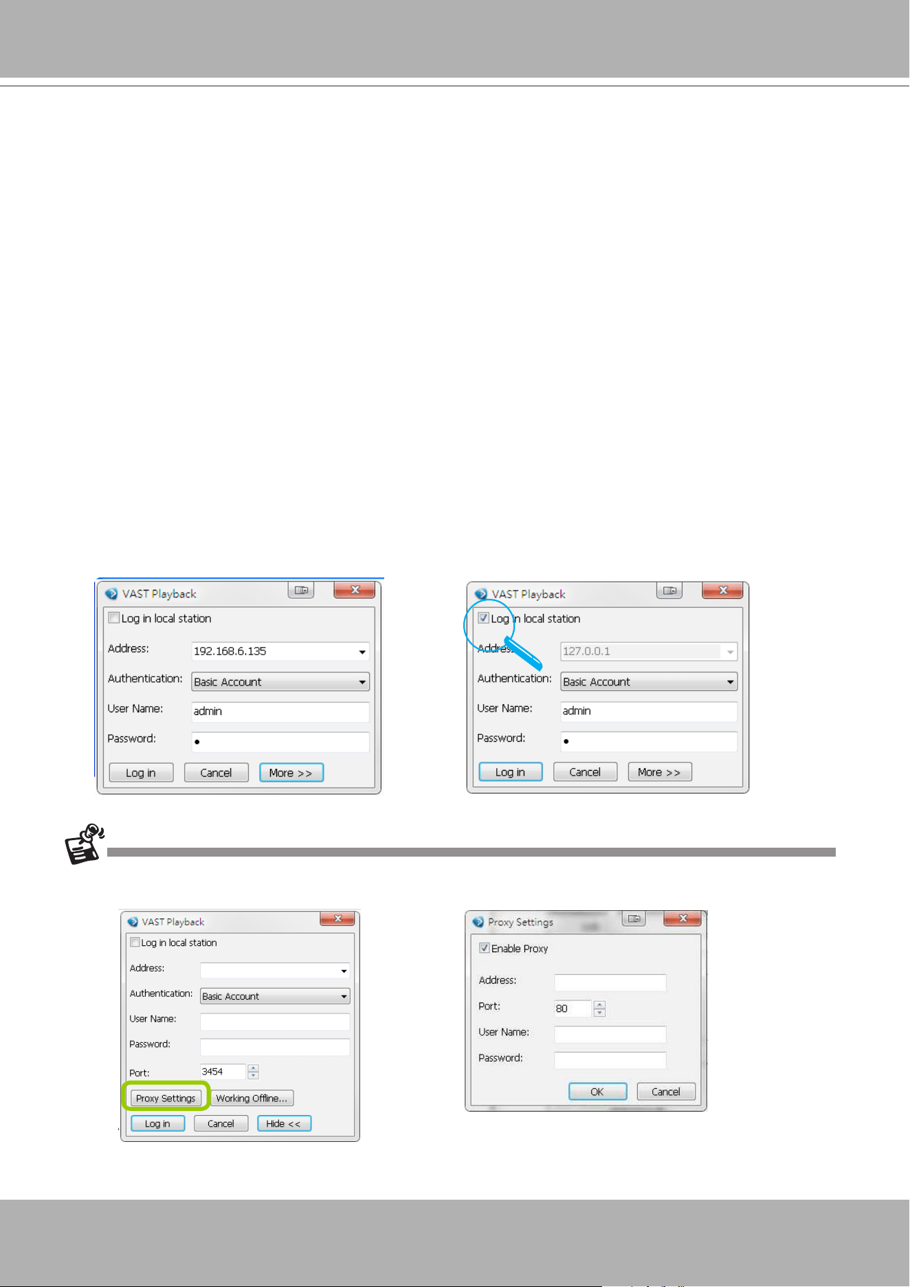
VIVOTEK - A Leading Provider of Multimedia Communication Solutions
274 - User's Manual
VAST Playback Conguration
Activating VAST Playback and Logging in to a Server
VAST Playback allows you to search and playback recorded media data from VAST Server.
Once you insert a device into the hierarchical management tree of VAST LiveClient, it will
automatically be displayed on the hierarchical management tree of VAST Playback. You can
then begin to use VAST Playback to view recorded or backup video clips.
After installing the VAST Playback program, please follow the steps below to activate VAST
Playback:
1. Run the
VAST Playback
program. If you have already run VAST LiveClient, you can also click
System
> Launch Playback
to activate VAST Playback.
2. A
Login
window will pop up. Fill in the information as shown below:
If you want to login to a remote VAST Server, enter the
IP address
,
user name
,
password
and
communication port
of the server. Click
Log in
to login the target server or
Cancel
to exit the
system.
If you want to login to your local host which is running VAST Server, check the
Login local
station
checkbox, and the local
IP Address
will be displayed automatically. Enter the
User Name
,
Password
, and
Communication Port
of the local server to log in. Click
Login
to log in to the target
server or
Cancel
to exit the system.
3. The VAST Playback main window will be displayed.
If your network environment need to set up proxy, click
More >>
to extend the login window, then click
Proxy
Setting
to open the dialog. Then enter related information to link to your proxy server.
Available functions of the VAST Playback program will be enabled according to the role of your login account. For
more details about the privileges of the user account, please refer to
How to Manage User Accounts
on page
150.
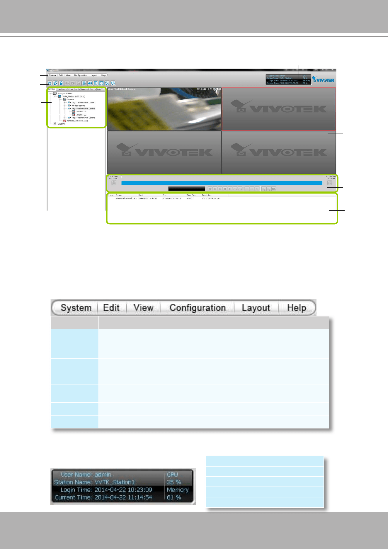
VIVOTEK - A Leading Provider of Multimedia Communication Solutions
User's Manual - 275
VAST Playback User Interface
A. Menu bar B. Quick access bar C. Query panel (Browsing / Time search / Bookmark search /
Event search / Alarm search / Log viewer) D. Status panel E. Recorded video playback window
F. Playback control panel
G. Video clips list
Menu Bar
Status Panel
Menu Item Drop-down Options
System
Lock / Language / Launch LiveClient / Logout / Exit
Edit
Snapshot / Print / Snapshot zoomed image / Print zoomed image / Find
View
Logical Tree View / Device Tree View / Backup Status /Exporting Status /
Browsing / Time Search / Event Search / Bookmark search / Alarm search /
Log Viewer / Full Screen / Minimize / Query Panel / Video Clips List
Conguration
Client Settings (Snapshot Settings / Export Settings / View Settings / Proxy
Settings / General Settings / PiP Settings)
Layout
Change Layout
Help
About
User Name
Station Name (IP Address)
Login Time (yyyy-mm-dd hh:mm:ss)
Current Time (yyyy-mm-dd hh:mm:ss)
CPU and memory usage in percentage
G
D
A
E
B
C
F
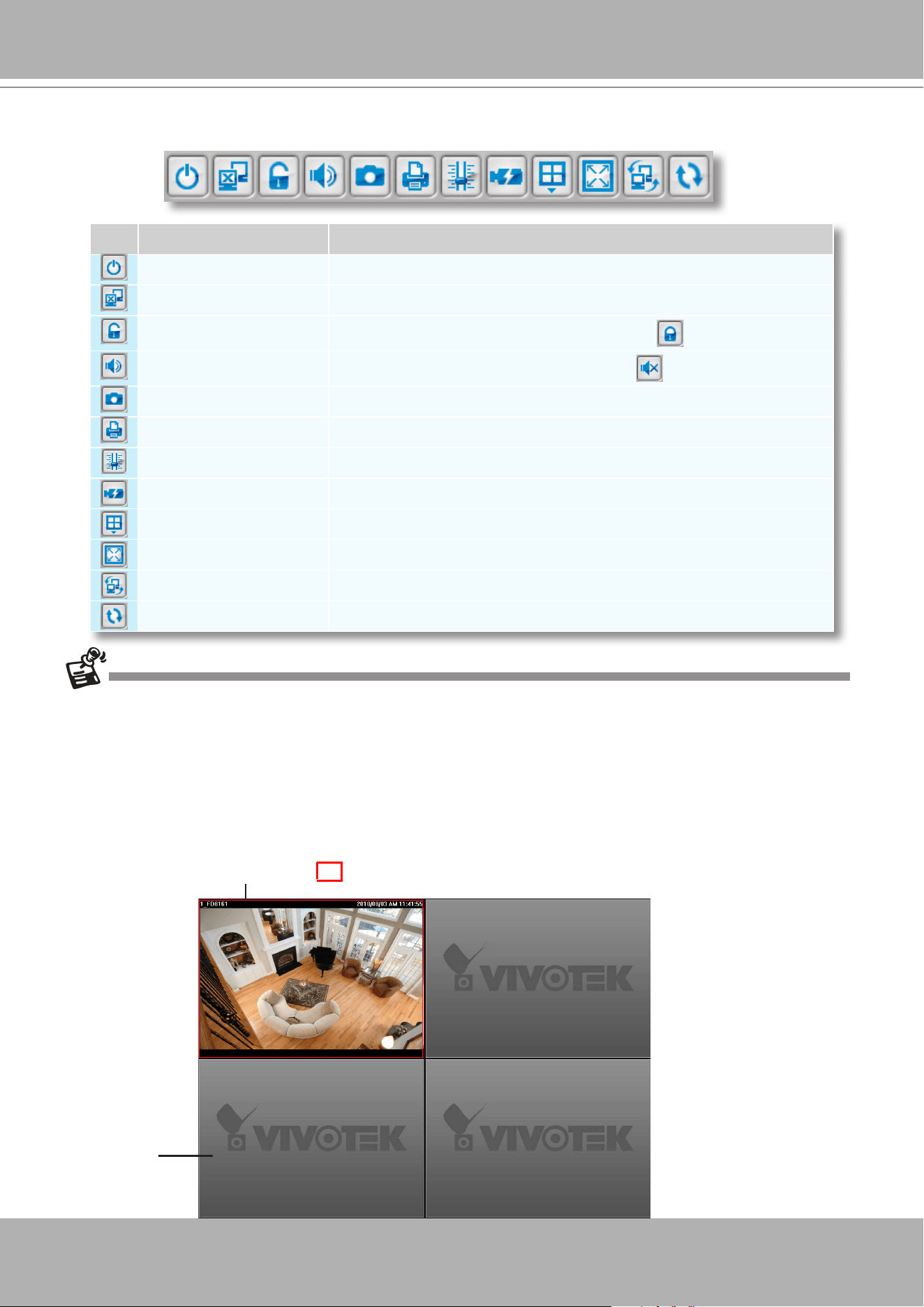
VIVOTEK - A Leading Provider of Multimedia Communication Solutions
276 - User's Manual
Quick Access Bar
Some buttons will be disabled if the selected device does not support those functions.
Recorded Video Playback Window
The "VIVOTEK" logo indicates that no camera has been assigned to the video cell.
Icon Function Description
Exit
Exit the system
Logout
Logout from the current station
Lock
Click to Lock the system for security concerns (
Unclock the system)
Volume
Adjust the audio volume of the target video (
Mute)
Snapshot
Capture the picture of the target video
Print
Print out the picture of the target video
SVC Level
Exert SVC control of video playback frame rate
Remove All Connection
Remove all live videos from the live video monitoring window
Layout
Change the layout of video monitoring window
Full Screen
Maximize the live video monitoring window
Switch Screen
Switch to another screen
Synchronous Playback
Click to enable synchronous playback for multiple channels
The red frame ( ) represents the focused cell.
Video Cell
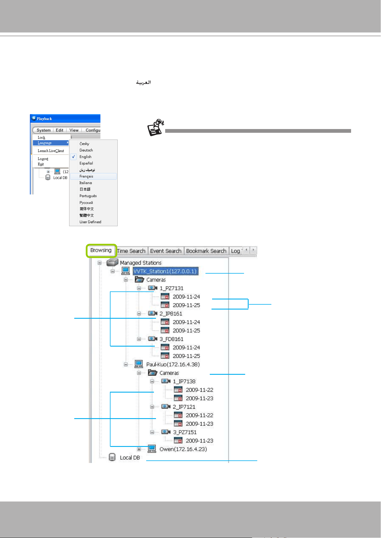
VIVOTEK - A Leading Provider of Multimedia Communication Solutions
User's Manual - 277
Language Selection
VAST current supports user interfaces in multiple languages; and language options are availabe
in: English, Deutsch, Español,
,
Français, Italiano,
日本語
, Português,
Ρусский
,
簡体中文
,
and
繁體中文
, User Dened If you want to select another language for the interface, please click
System > Language
on the menu bar to select a desired language. Please note that if you want
to change the language option, a message will remind you to restart the system.
Query Panel-- Browsing Page
Dates with recorded
video clips
Devices listed
under the root
station
If you want to use "User Dened" language, please prepare images and
language strings, and upload the les to the following folders:
...\VAST\Client\Playback\language\zz_UD (language string)
...\VAST\Client\Playback\image (images)
Local Database
Root Station Name (IP address)
Sub-station Name (IP address)
Devices listed
under the sub-
station
You can hide this panel in order to maximize the single playback view from the
View
menu.
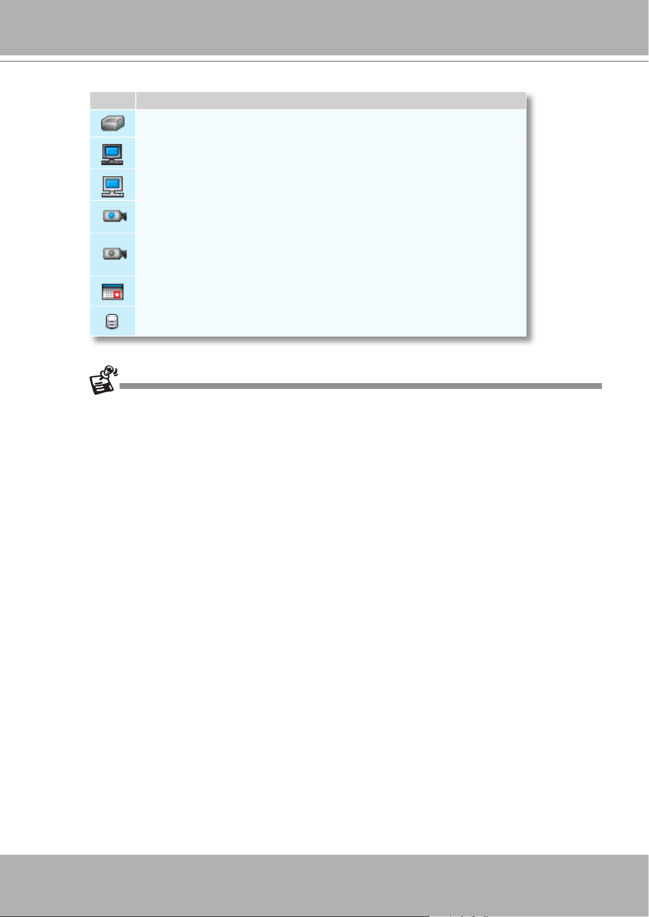
VIVOTEK - A Leading Provider of Multimedia Communication Solutions
278 - User's Manual
Icon Description
Station list including server and local database
A station (a computer that has installed VAST Server)
A station (a computer that has installed ST7501 Server)
The camera that exists on the hierarchical management tree of LiveClient.
The camera that has been removed from the hierarchical management tree of
LiveClient (off-line). However, its recorded video (if any) is still accessible from
the server.
Dates with recorded video clips.
Local database for backup data. For more information about how to upload
backup data to the list, please refer to page 300.
See page 267 for how to congure a Logical Tree View.
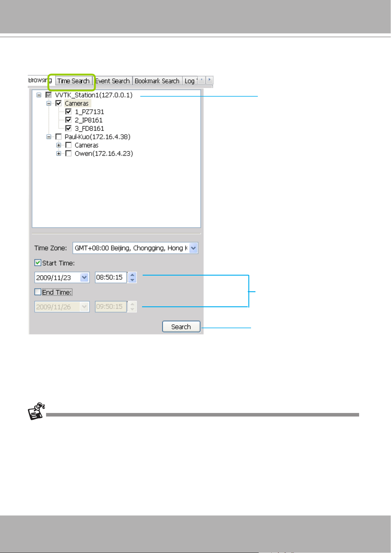
VIVOTEK - A Leading Provider of Multimedia Communication Solutions
User's Manual - 279
Query Panel--Time Search Page
The
Time Zone
setting is automatically synchronized with that on your client computer.
Select station(s)/ device(s) that
you want to search for recorded
les
Specify search period of time
Click to start to search, the
results will be shown on the
video clips list
You can hide this panel in order to maximize the single playback view from the
View
menu.
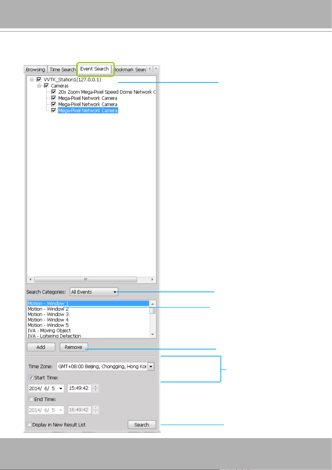
VIVOTEK - A Leading Provider of Multimedia Communication Solutions
280 - User's Manual
Select an Event Category
Specify search period of time
Click to start to search, the
results will be shown on the
video clips list
Click to add search criteria
Query Panel--Event Search Page
Click to remove search criteria
Select station(s)/ device(s) that
you want to search for recorded
les
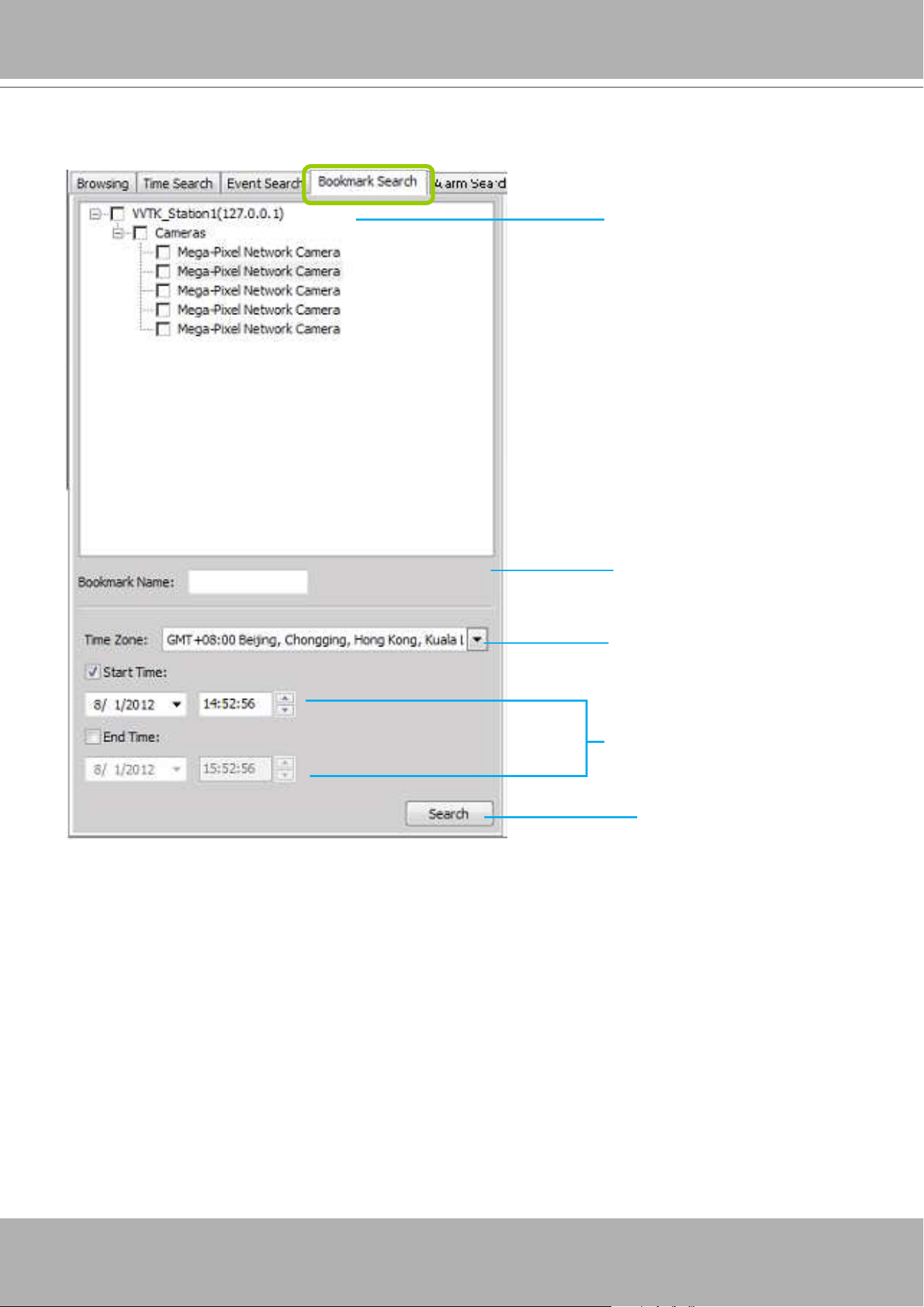
VIVOTEK - A Leading Provider of Multimedia Communication Solutions
User's Manual - 281
Query Panel--Bookmark Search Page
Select a name to serach for
Select a time zone
Specify search period of time
Click to start to search, the
results will be listed on the
video clips list
Select station(s) that you want
to search for bookmarks
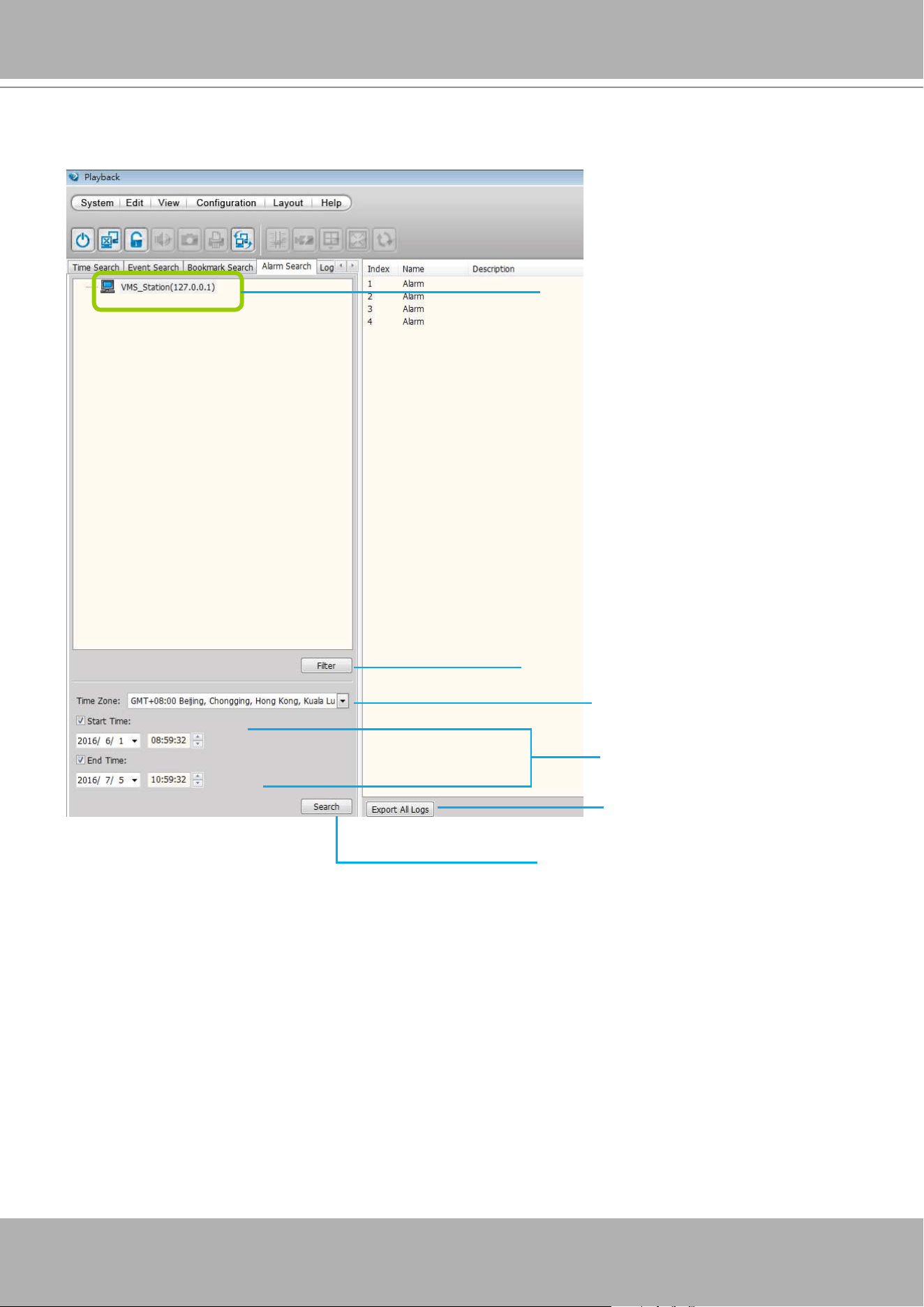
VIVOTEK - A Leading Provider of Multimedia Communication Solutions
282 - User's Manual
Query Panel--Alarm Search Page
Click to congure the search conditions
Select a time zone
Specify search period of time
Click to start to search, the
results will be listed on the
video clips list
Select station(s) that you want
to search for bookmarks
Click to export a log les for
the occurrences of alarms
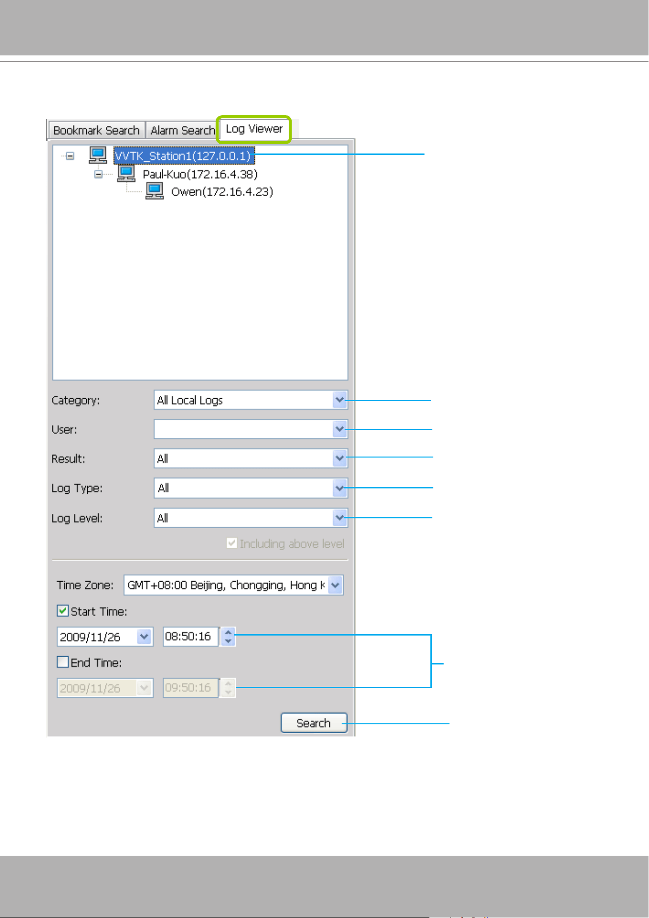
VIVOTEK - A Leading Provider of Multimedia Communication Solutions
User's Manual - 283
Query Panel--Log Viewer Page
Select a Log Category
Select a User Account
Select a Result Type
Select a Log Type
Select a Log Level
Specify search period of time
Click to start to search, the
results will be listed on the
video clips list
Select station(s) that you want
to search for recorded logs
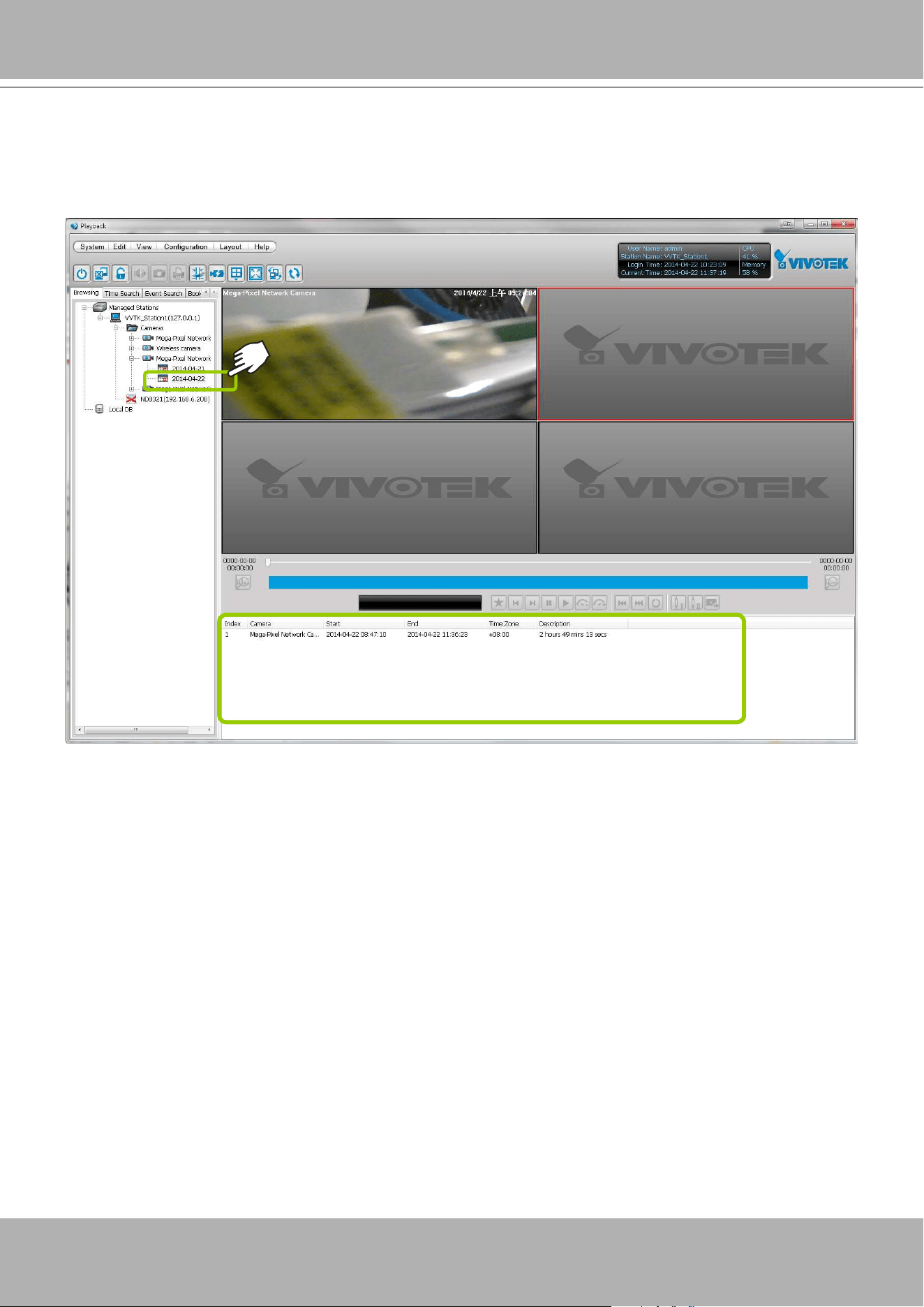
VIVOTEK - A Leading Provider of Multimedia Communication Solutions
284 - User's Manual
Video Clips List Window
If you select an
option “date”
, the video clips will be displayed in the video clips list window. An
option “date” may contain more than one video clip.
You can hide this panel in order to maximize the single playback view from the
View
menu.
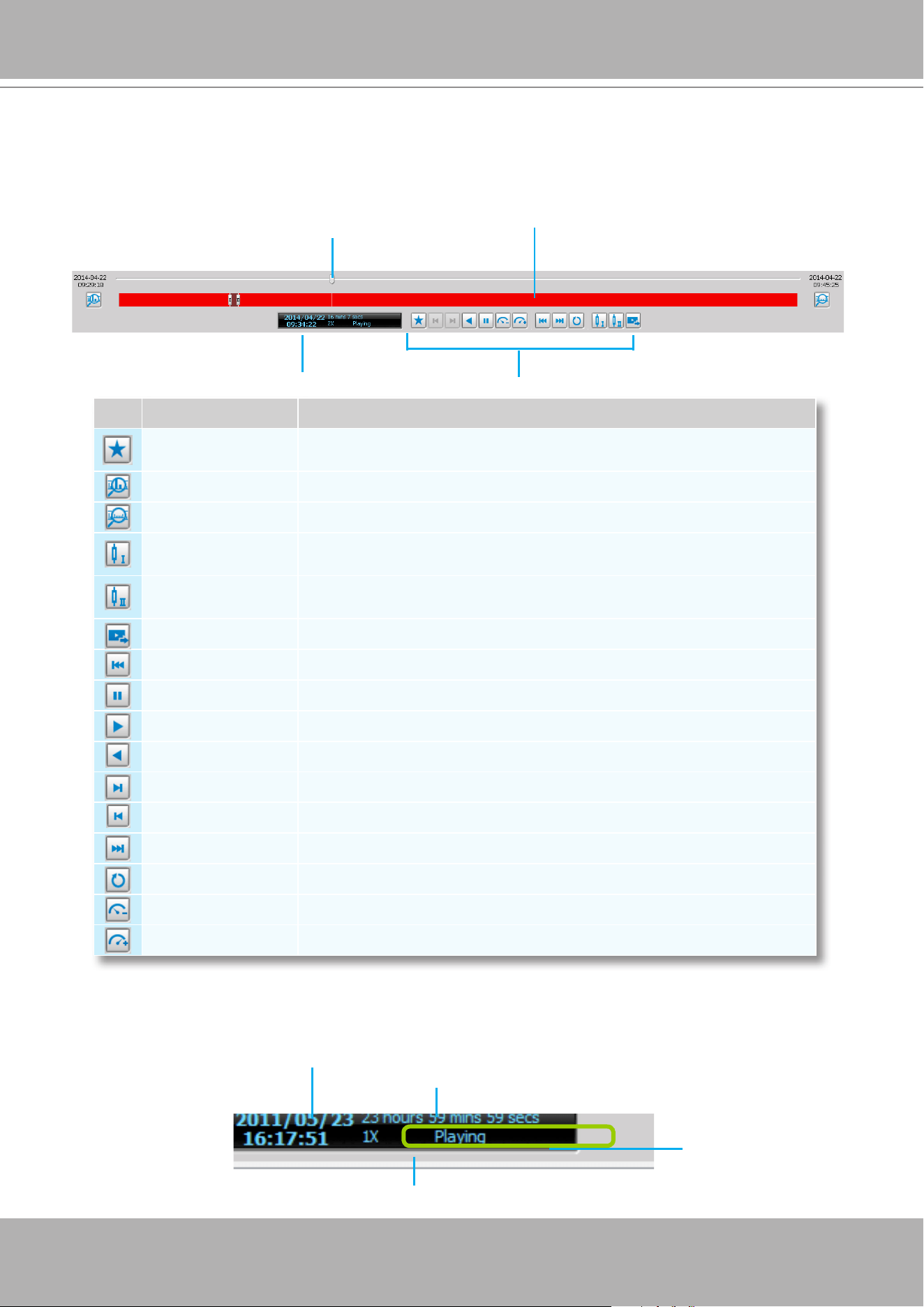
VIVOTEK - A Leading Provider of Multimedia Communication Solutions
User's Manual - 285
Playback Control Panel
When you double-click a video clip to play, the playback control panel will be enabled for you to
use.
Icon Function Description
Add Bookmark
Manually add a bookmark to pinpoint and extract a 20-second video clip
from an existing recording
Histogram Zoom In Zoom in on the displayed period of time of the histogram
Histogram Zoom Out Zoom out of the displayed period of time of the histogram
Marker I
If you want to export part of the recorded video clip, click to set marker I
on the histogram, which will be the start time of the exported media
Marker II
If you want to export part of the recorded video clip, click to set marker II
on the histogram, which will be the end time of the exported media
Export Media Click to export the selected section of video clip
Last Time Interval Go to the previous video clip on the video clips list
Pause Pause playback the selected video clip
Play Start to playback the selected video clip
Rewind Reversely plays back the current video
Next Frame Go to the next video frame of the selected video clip
Previous Frame Displays the previous frame
Next Time Interval Go to the next video clip on the video clips list
Repeat Mode Playback the selected video clip repeatly
Slow Down Slow down the playback rate
Speed Up Speed up the playback rate
Current time of the video clip
Total length of the histogram
The playback status
(Stop/Playing)
The playing rate can be 1/8, 1/4, 1/2, 1X, 2X, 4X, 8X, 16X, 32X, and 64X.
Playback Timeline Slider
Playback Status Panel
Playback Control Buttons
Playback Histogram
(Displays the period of time of the
video clip being played back)

VIVOTEK - A Leading Provider of Multimedia Communication Solutions
286 - User's Manual
Rewind
The Rewind function enables users to reversely playback from a specic point in time on a video
playback window. Once the occurrence of an event is ensured, this function can facilitate the
process of nding the evidences that appeared before the occurrence.
The Rewind function also applies to the Synchronous Playback mode. The following also apply:
1. The maximum playback speed is 64x. (I-frame only when speed is higher than 16x)
2. When you pull the time slider during the Rewind playback, short interruptions may occur.
3. When switching from the playback mode to the Rewind playback, the playback speed remains
the same. The same applies when switching from Rewind to the playback mode.
Limitations:
1. Short delays may occur when switching from playback to rewind, due to limitations by the
hard disk access speed and network speed.
2. When doing the forward playback, the previous frame function is not available. When doing
the rewind playback, the next frame function is not available.
3. The Rewind playback on multiple streams requires system performance resources.
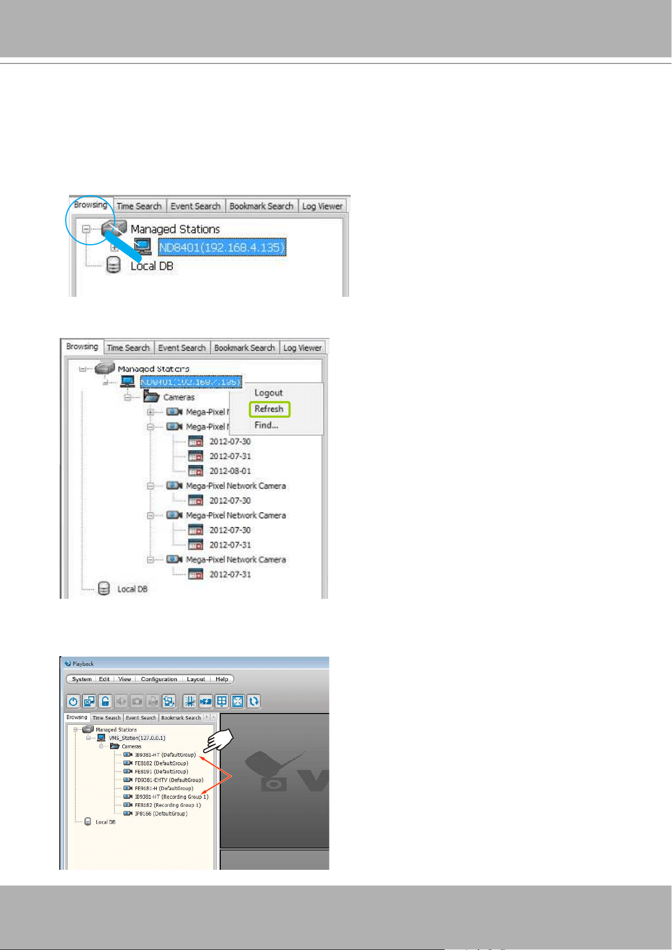
VIVOTEK - A Leading Provider of Multimedia Communication Solutions
User's Manual - 287
How to Playback Recorded Video
Select a Recorded Video Clip
Please follow the steps below to select a video clip:
1. On the
Bowsing
page, click the plus sign (+) to expand the hierarchical management tree.
2.
Right-click
a station, device, or option “date” on the hierarchical management tree and click
Refresh
to display the recorded video clips.
If a camera is congured with Multiple Stream recording, all its recording group congurations will be
listed on the device tree.
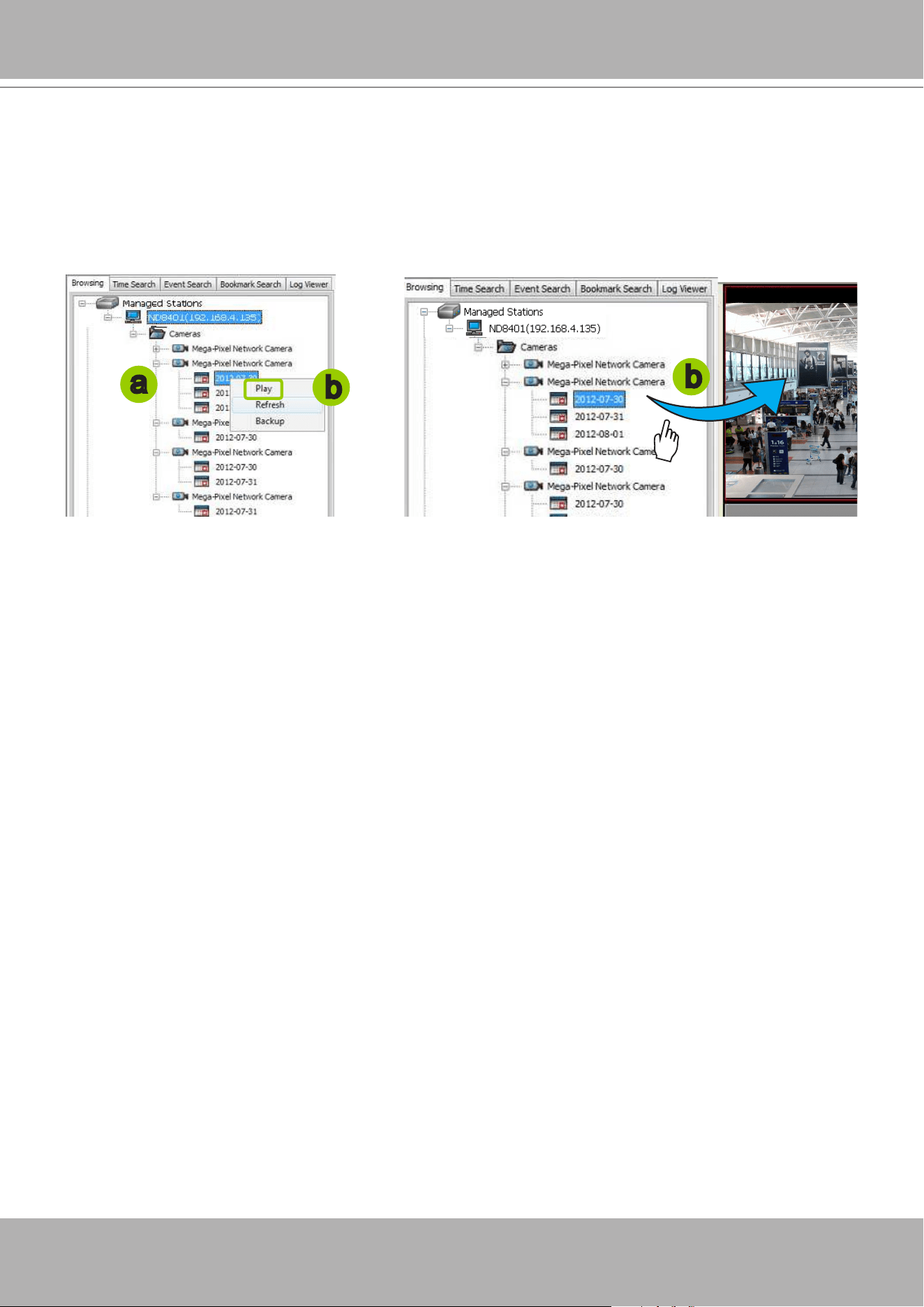
VIVOTEK - A Leading Provider of Multimedia Communication Solutions
288 - User's Manual
3. There are two ways to view the video clips of a date.
View all video clips of a date:
a. Select an
option
“date” from the hierarchical management tree.
b.
Double-click
the option “date” or
right-click
the option “date” and click
play
, and it will start to
play in an available video cell. (You can also directly
drag-and-drop
the
opti
on “date” to a desired
video cell in the recorded video playback window. The video clip will start to play.)
Mega Pixel Network Camera
a
b
b
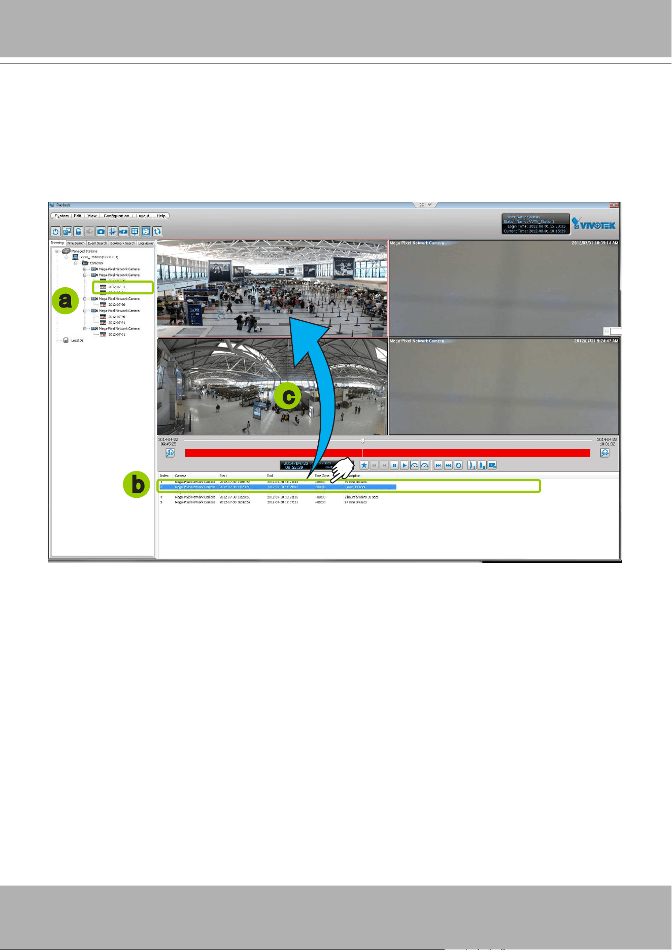
VIVOTEK - A Leading Provider of Multimedia Communication Solutions
User's Manual - 289
View only one of the video clips of a date:
a. Click on a “date” on the hierarchical management tree. The corresponding video clips will be listed
in the video clip list window.
b. Select a video clip from the video clip list window.
c.
Double-click
the video clip, then it will start to play in an available video cell. (You can also directly
drag-and-drop
the video clip to a desired video cell in the recorded video playback window. The
video clip will start to play.)
4. Then you can make use of the playback control panel to playback the selected video clip. Please refer
to
Playback Control Panel
on page 285.
a
b
c
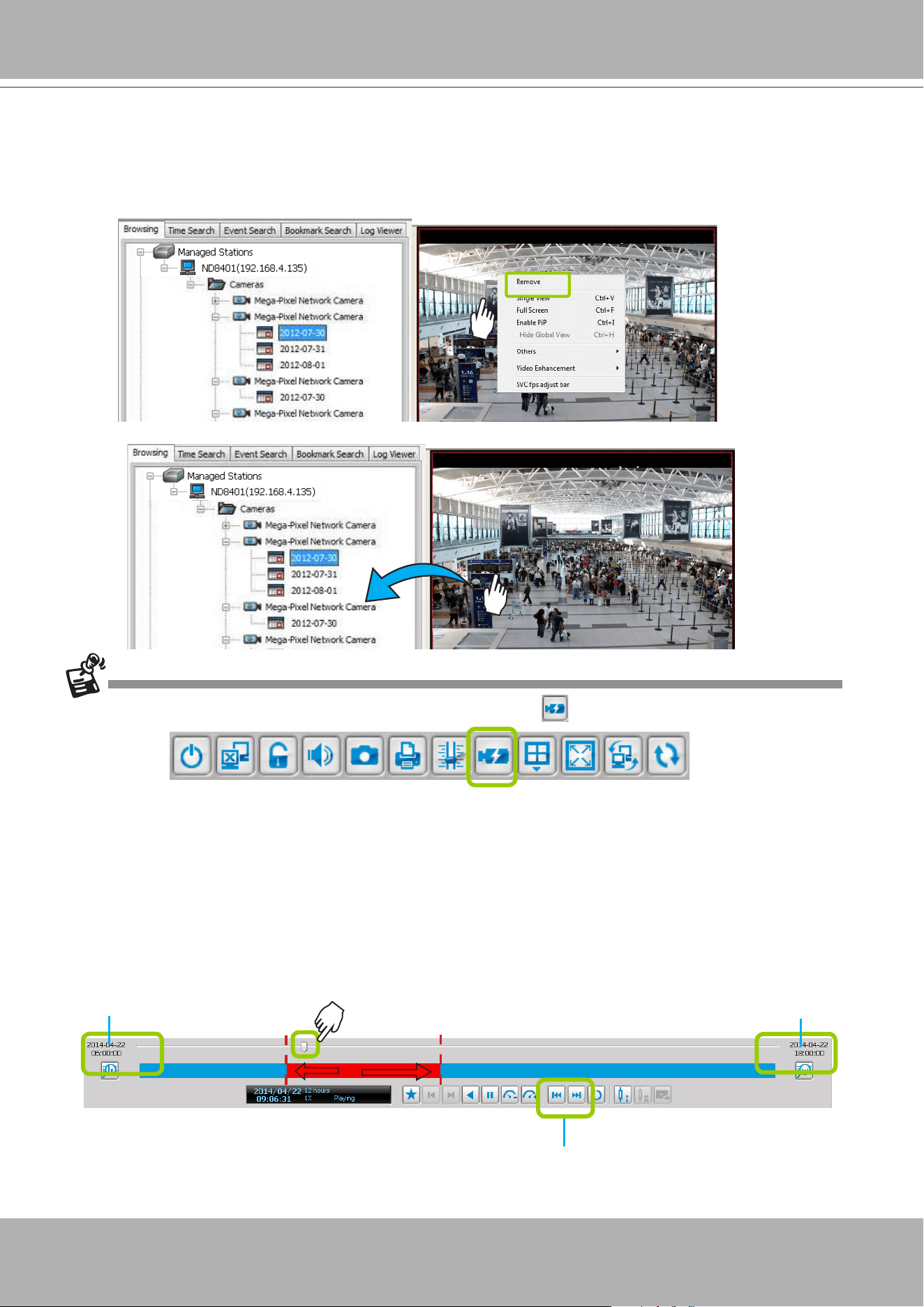
VIVOTEK - A Leading Provider of Multimedia Communication Solutions
290 - User's Manual
Remove Recorded Video Clips from Video Cells
There are two ways to remove a recorded video clip from the video cell:
1.
Right-click
the video cell and select
Remove
.
2.
Drag-and-drop
the live view from the video cell to the hierarchical management tree window.
If you want to remove all live videos from the video cells, please click on the menu bar.
Timeline Slider Bar and Histogram
The red part of the histogram shows the period of time of a video clip. The timeline slider bar will move
forward as the video is on playback. You can manually move forward/backward the
Timeline Slider Bar
to the desired position as shown below.
The current time of the video clip will be displayed on the status panel. It will change according to the
current position of the timeline slider bar.
Mega Pixel Network Camera 2012/07/31PM
Mega Pixel Network Camera 2012/07/31PM
Start time of the histogram End time of the histogram
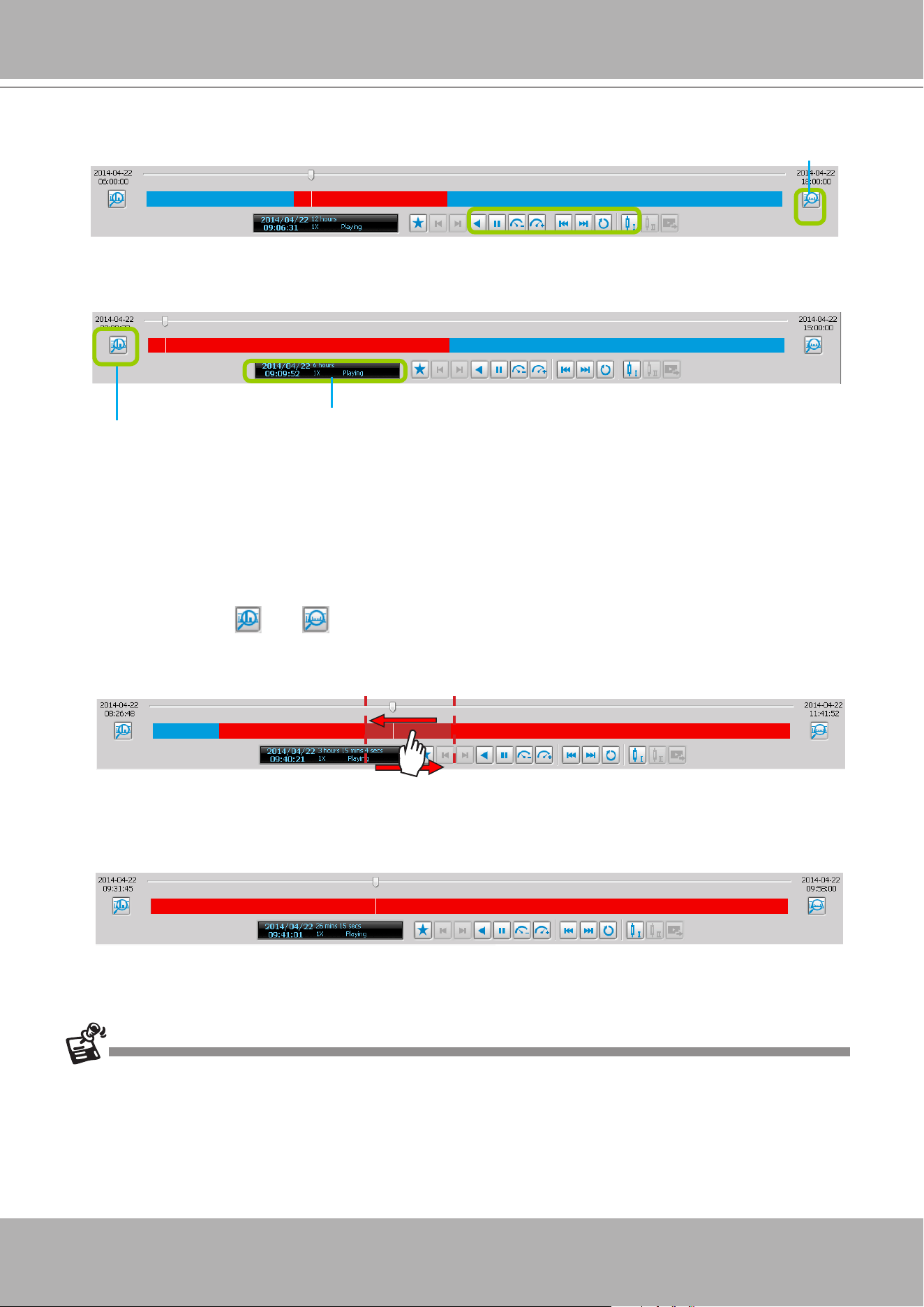
VIVOTEK - A Leading Provider of Multimedia Communication Solutions
User's Manual - 291
Zoom in / out of the Histogram
As the second picture shows, by clicking
Histogram
Zoom In
, the total time of the histogram will shorten
to half of the original period of time, while the red part of the histogram that shows the period of time of
the video clip will extend to twice the original time span.
In addition to clicking and to zoom in/ out of the histogram, you can use the mouse directly to
drag the histogram to zoom in part of the focused video clip.
For example:
a. Drag a section of the histogram. You can drag it to either direction.
b. The section will be extended as shown below.
For more functions of the playback control buttons, please refer to page 285 for detailed description.
Histogram zoomed in
Histogram zoom out
Total time length
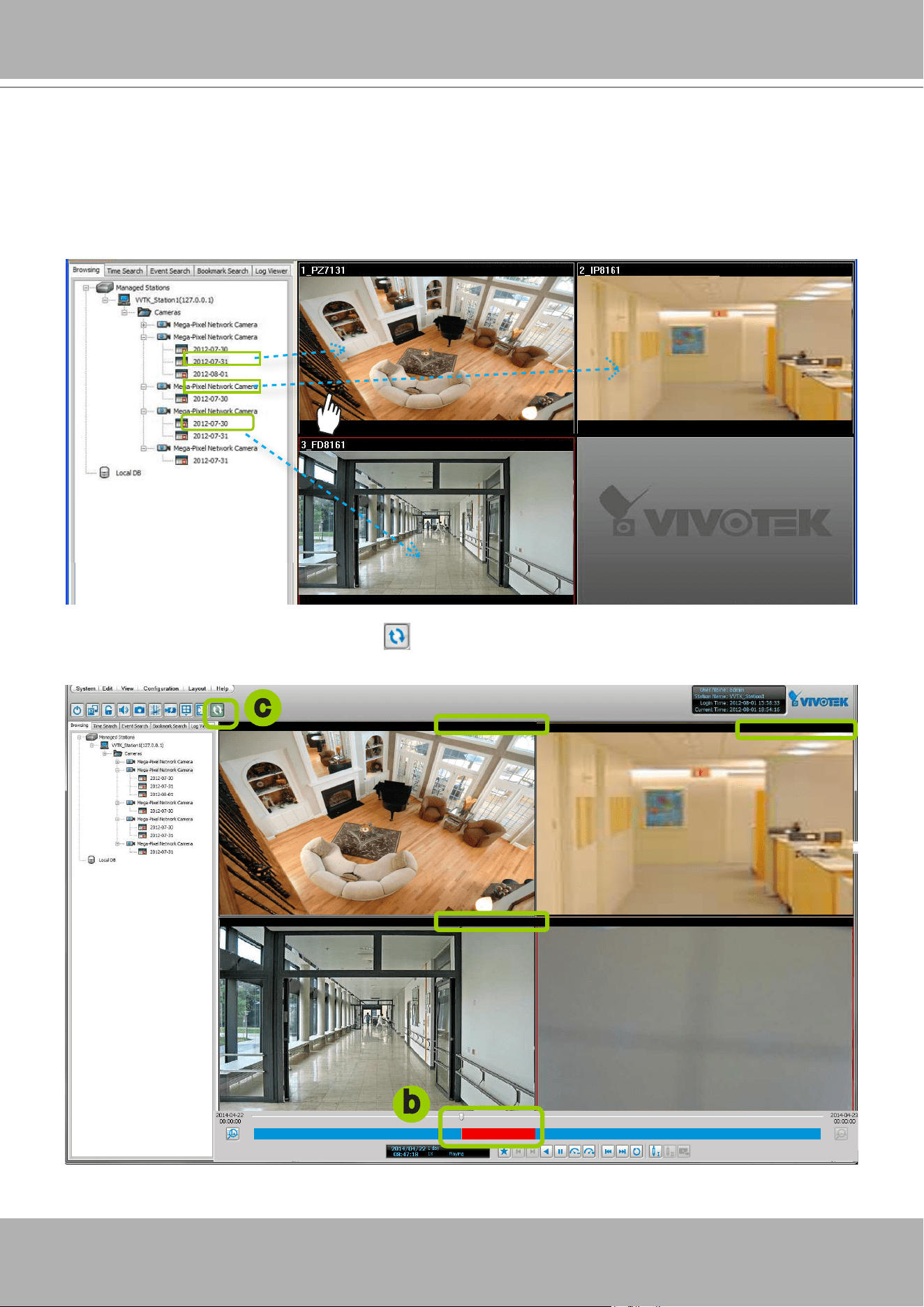
VIVOTEK - A Leading Provider of Multimedia Communication Solutions
292 - User's Manual
Synchronous Playback
VIVOTEK VAST Playback supports synchronous playback, which allows you to review up to
16-channel video clips simultaneously during the specic time point.
Please follow the steps below to enable synchronous playback:
a. Drag-and-drop the option “date”s to the video cells.
b. Drag the Timeline Slider Bar to the specic time point.
c. Click the synchronous playback button
on the quick access bar. The selected channel will start to
sychronously playback as shown below.
2012/07/31 11:02:03PM
2012/07/31 11:02:03PM
2012/07/31 11:02:03PM
2012/07/31 11:02:03PM
b
c
2012/07/31 11:02:03PM2012/07/31 11:02:03PM
2012/07/31 11:02:03PM
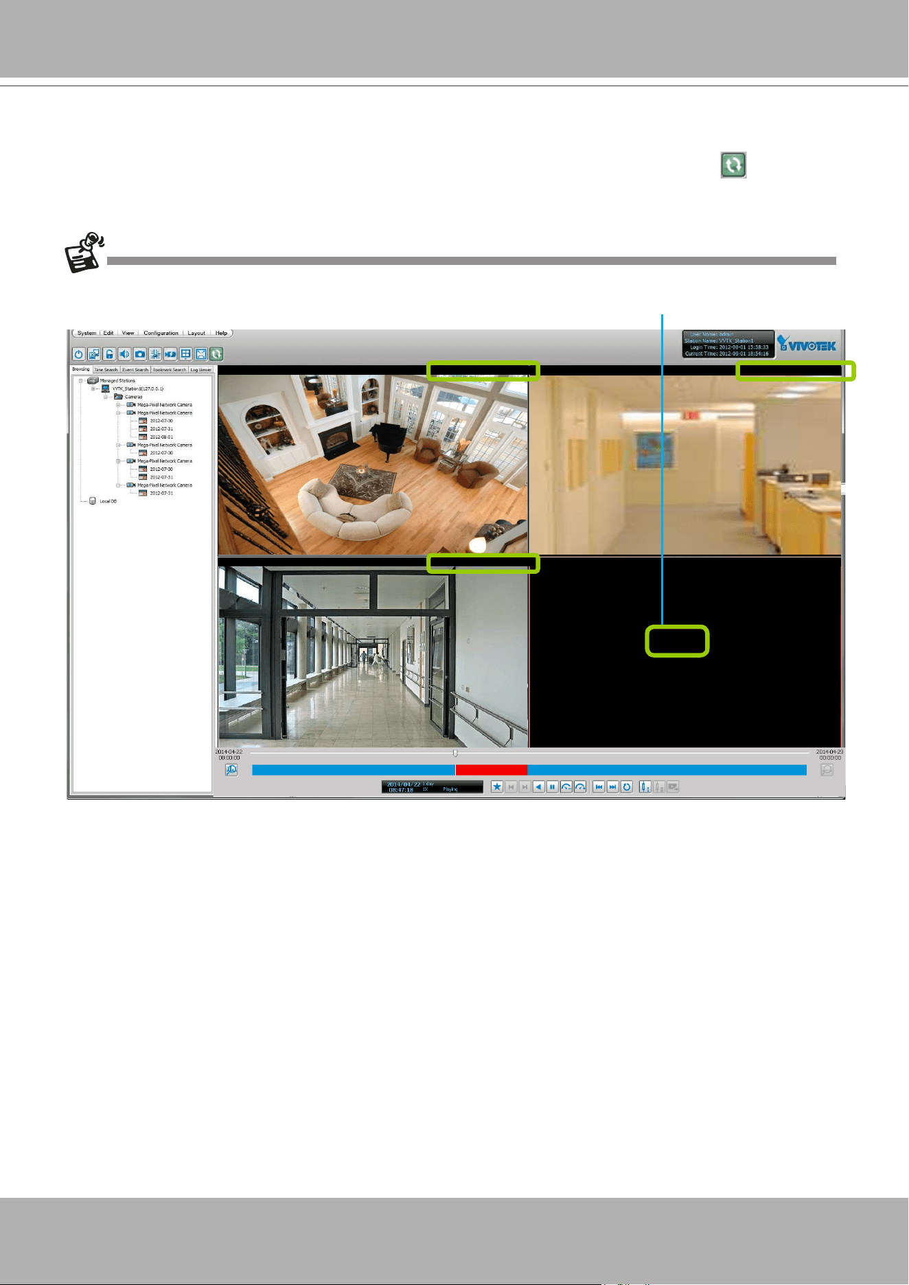
VIVOTEK - A Leading Provider of Multimedia Communication Solutions
User's Manual - 293
d. You can move forward/backward the Timeline Slider Bar to another time point, and all of the time
stamps on the video cells will change accordingly.
e. If you want to stop synchronous playback, click the non-synchronous playback button again.
The following illustration shows that during the specic time, there is no recorded video on the camera.
2012/07/31 11:02:03PM
2012/07/31 11:02:03PM
2012/07/31 11:02:03PM
2012/07/31 11:02:03PM
No Data
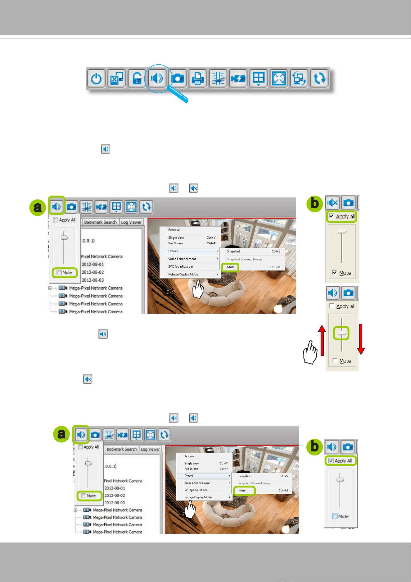
VIVOTEK - A Leading Provider of Multimedia Communication Solutions
294 - User's Manual
Audio Control
The audio function will be enabled if the device is equipped with an internal or external
microphone. Please follow the steps below to adjust the volume or turn on/off the audio of the
focused video:
To turn off the audio (Mute Mode)
a. Click
Audio On
on the quick access bar and check
Mute
. Or you can
right-click
on the video
cell to open the popup menu, then click
Others > Mute
. The mute option in the popup menu will then
be selected.
b. If you want to turn off the audio of all live video, select
Apply all
.
c. The Audio icon will then change from to .
To adjust the audio volume
a. Click
Audio On
on the quick access bar.
b. Drag-and-drop the slider bar. Slide to a higher position for louder volume.
To turn on the audio
a. Click
Mute
on the quick access bar and uncheck
Mute
. Or you can
right-click
on the video cell
to open the popup menu, then click
Others > Mute
. The mute option in the popup menu will then be
unchecked.
b. If you want to turn on the audio of all live video, select
Apply all
.
c. The Audio icon will then change from to .
b
a
a
b
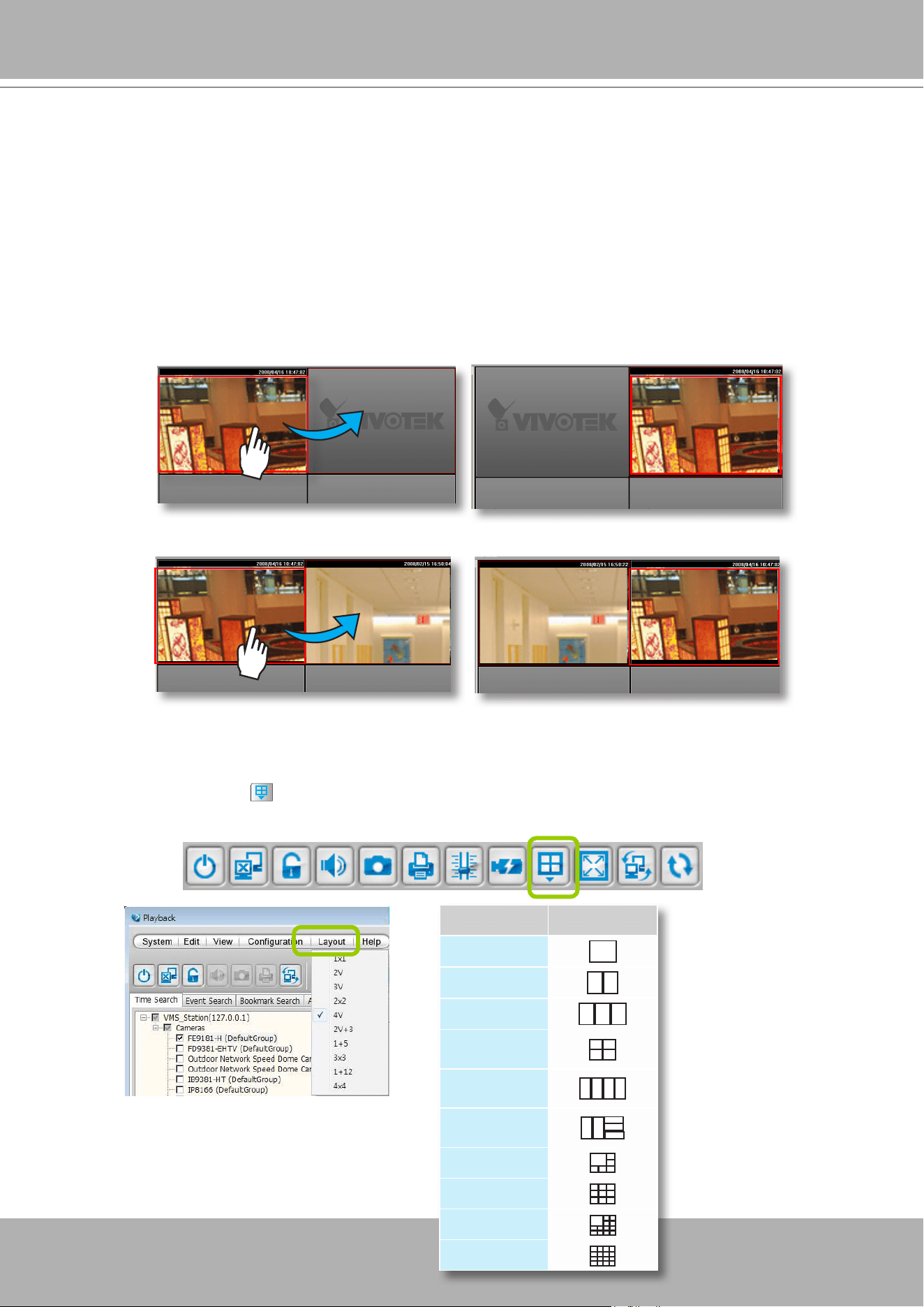
VIVOTEK - A Leading Provider of Multimedia Communication Solutions
User's Manual - 295
How to Change the Playback Layout
Changing the Layout of the Recorded Video Playback Window
VIVOTEK VAST Playback supports up to 16-CH simultaneous recorded video playback on a
single monitor and allows you to change the layout of the recorded live video playback window
based on the number of inserted devices.
Switch Video Channels
Drag-and-drop
a video channel to another empty video window.
To switch two channels,
drag-and-drop
one view to the other, then the two channels will switch
positions.
Congure Layout Mode
Click the
Layout
button on the quick access bar or click
Layout > Change Layout
on the menu bar.
Select a desired layout mode and the layout window will change accordingly. Below we illustrate 6 types
of layout modes:
Layout mode Description
1 x 1
2V
3V
2 x 2
4V
2V+3
1 + 5
3 x 3
1 + 12
4 x 4
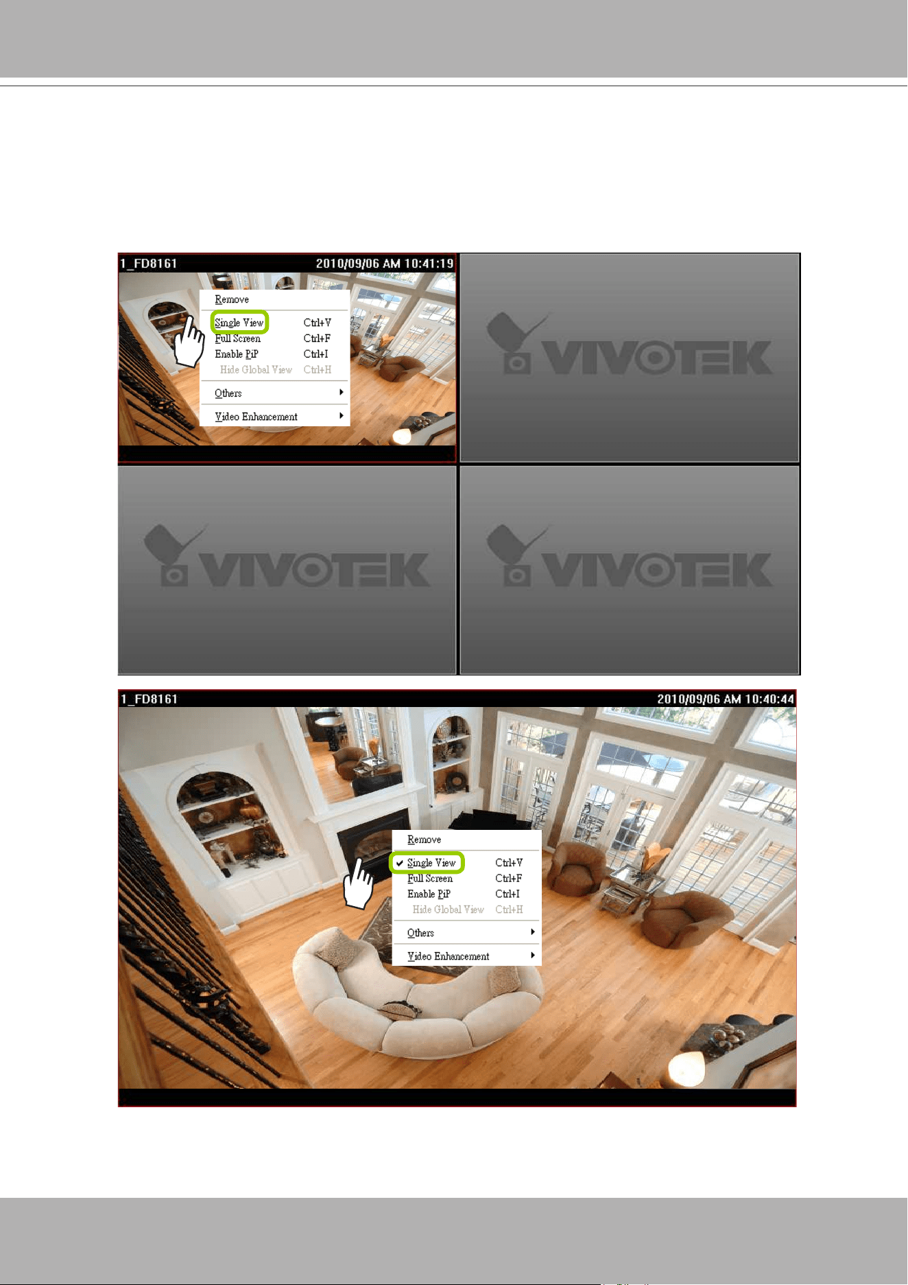
VIVOTEK - A Leading Provider of Multimedia Communication Solutions
296 - User's Manual
Maximize/Minimize the Recorded Video Playback Window
Single View: to maxmize a video cell to the entire video playback window
Double-click
the video cell, or
right-click
the video cell and selec
Single View
. The focused video will
occupy the entire Playback window as shown below.
To restore to the original layout,
double-click
the video cell or
right-click
the video cell and uncheck
Single View.
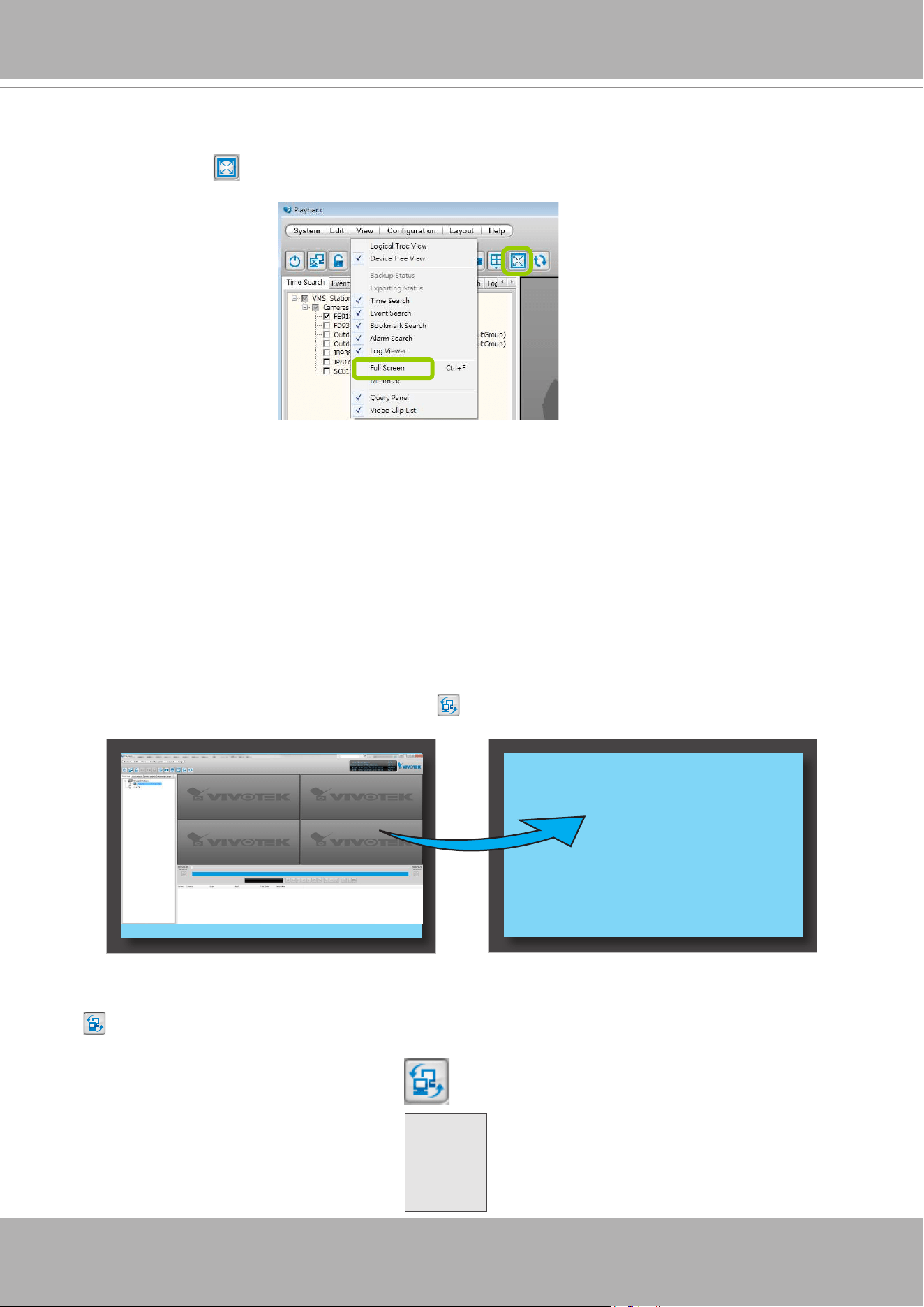
VIVOTEK - A Leading Provider of Multimedia Communication Solutions
User's Manual - 297
Full Screen: to maxmize the video playback window to the entire screen
Click
Full Screen
on the quick access bar or
right-click
the video cell and select
Full Screen
.
In addition, you can also click
View > Full Screen
on the menu bar to maximize the recorded video
playback window.
To restore to the original layout,
right-click
the video cell and uncheck
Full Screen
. You also can
press
the
Esc
button on the keyboard to leave the full screen mode.
Minimize:
If you click
View > Minimize
on the menu bar
,
the Playback window will minimize
to the Windows tool bar.
View Recorded Video with Multiple Monitors
If you have multiple screens in your control center, you can switch the VAST Playback Window
among these screens.
If you have two monitors, click
Switch Screen
on the menu bar, the Playback window of monitor 1
will switch to monitor 2.
If you have three or more monitors, a drop-down list will be displayed when you click
Switch Screen
on the menu bar. The number of options on this list depends on the number of your screens. Select
a desired screen from the drop-down list and the Playback Window will then switch to the specied
screen.
Monitor 1 Monitor 2
Monitor 1
Monitor 2
Monitor 3
......
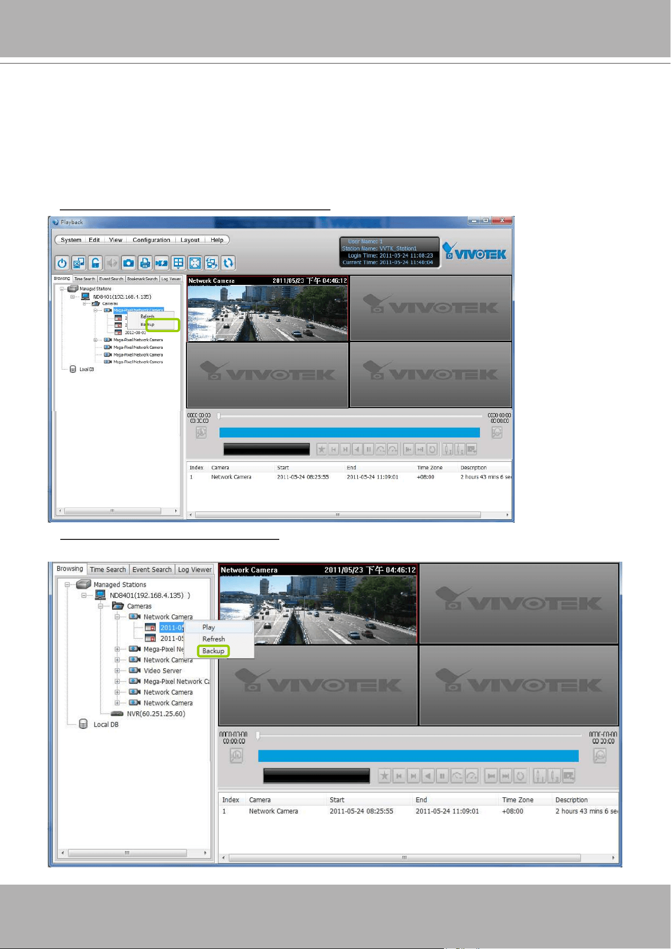
VIVOTEK - A Leading Provider of Multimedia Communication Solutions
298 - User's Manual
How to Backup Recorded Video
In addition to the Schedule Backup function of VAST LiveClient introduced on page 61, the
VAST Playback also features to backup recorded video clips from the
local database
. Please
open the
Browsing
page and follow the steps below to backup recorded video:
a. Select the target les.
To backup all recorded video of a selected device:
Right-click
the device and click
Backup
.
To backup all recorded video of the day:
Right-click
the option “date” and click
Backup
(or select the
date and click the
Backup
button below).
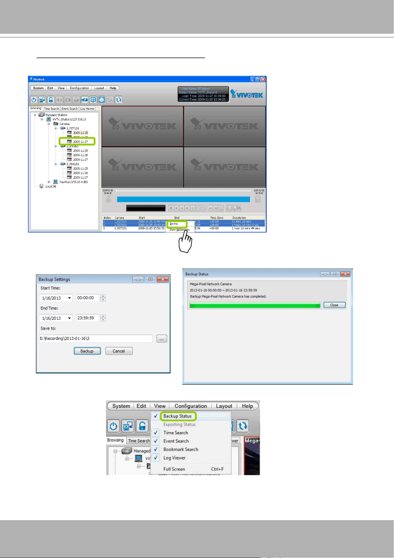
VIVOTEK - A Leading Provider of Multimedia Communication Solutions
User's Manual - 299
To backup part of the recorded video of the day: Select the date and choose the video clip(s)
from video clip window. Then
right-click
the selected option(s) and click
Backup
. Note: Use the
combination of the
Shift
key and left mouse click to select multiple video clips.
b. A
Backup Settings
window will pop up. Specify the time span and select a storage path, then click
Backup
. The system will start to backup and popup a window showing the backup status.
If you close the status window, you can also open it again by clicking
View > Backup Status
.
d. When the backup is complete, you will see an information dialog. The recorded data will be restored in
the specic folder.
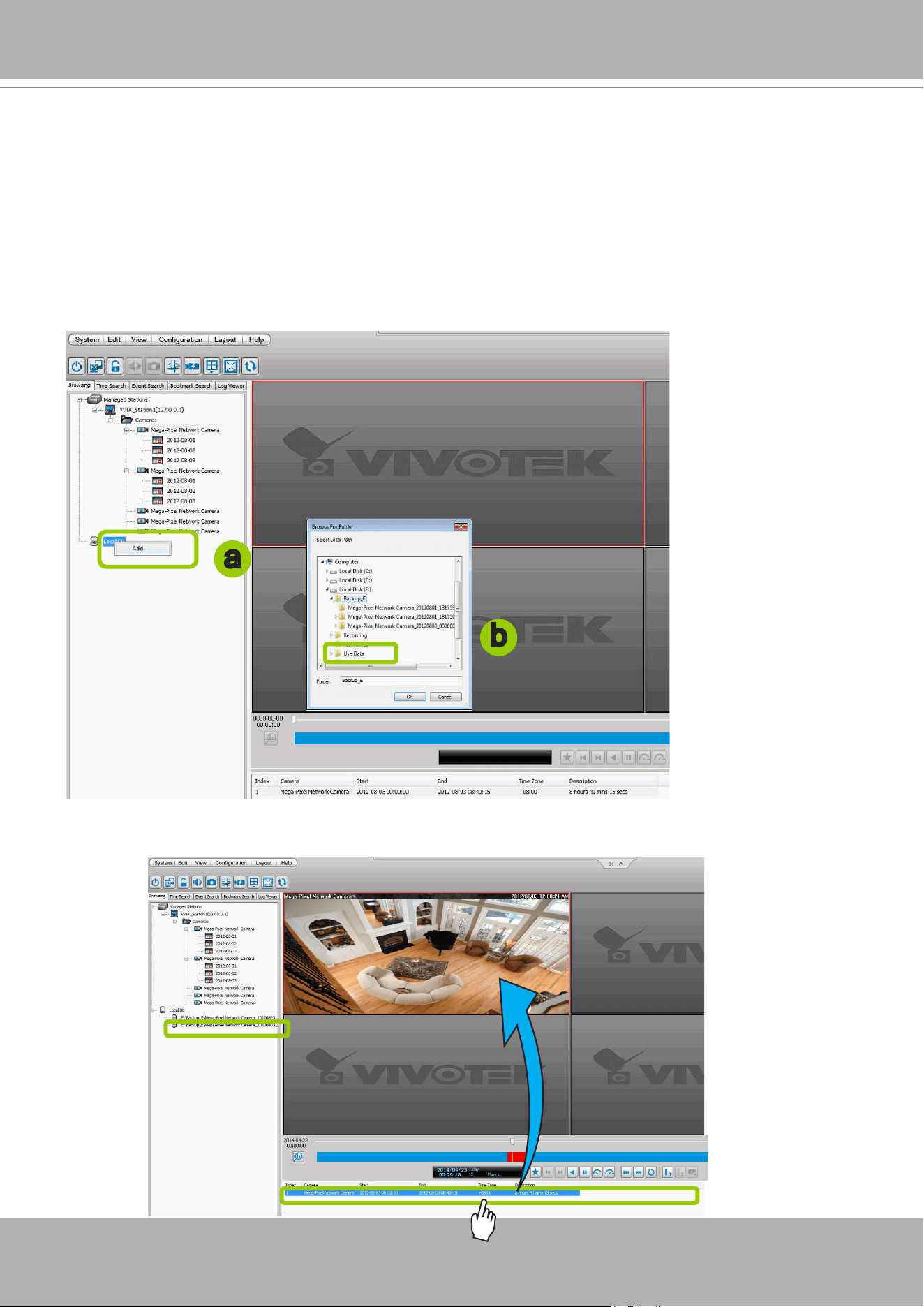
VIVOTEK - A Leading Provider of Multimedia Communication Solutions
300 - User's Manual
How to View Backup Files
The VAST Playback also allows users to playback backup les, including
Schedule Backup
by
VAST LiveClient and
Recorded Data Backup
by VAST Playback.
Please follow the steps below to view backup les:
a.
Right-click
Local DB and click
Add
.
b. A
Load Backup File
window will pop up as shown below. Select the
*.dif le
to upload.
c. The following is an example of uploaded le, and you can
double-click
it or
drag-and-drop
it to a
video cell to playback.
a
b
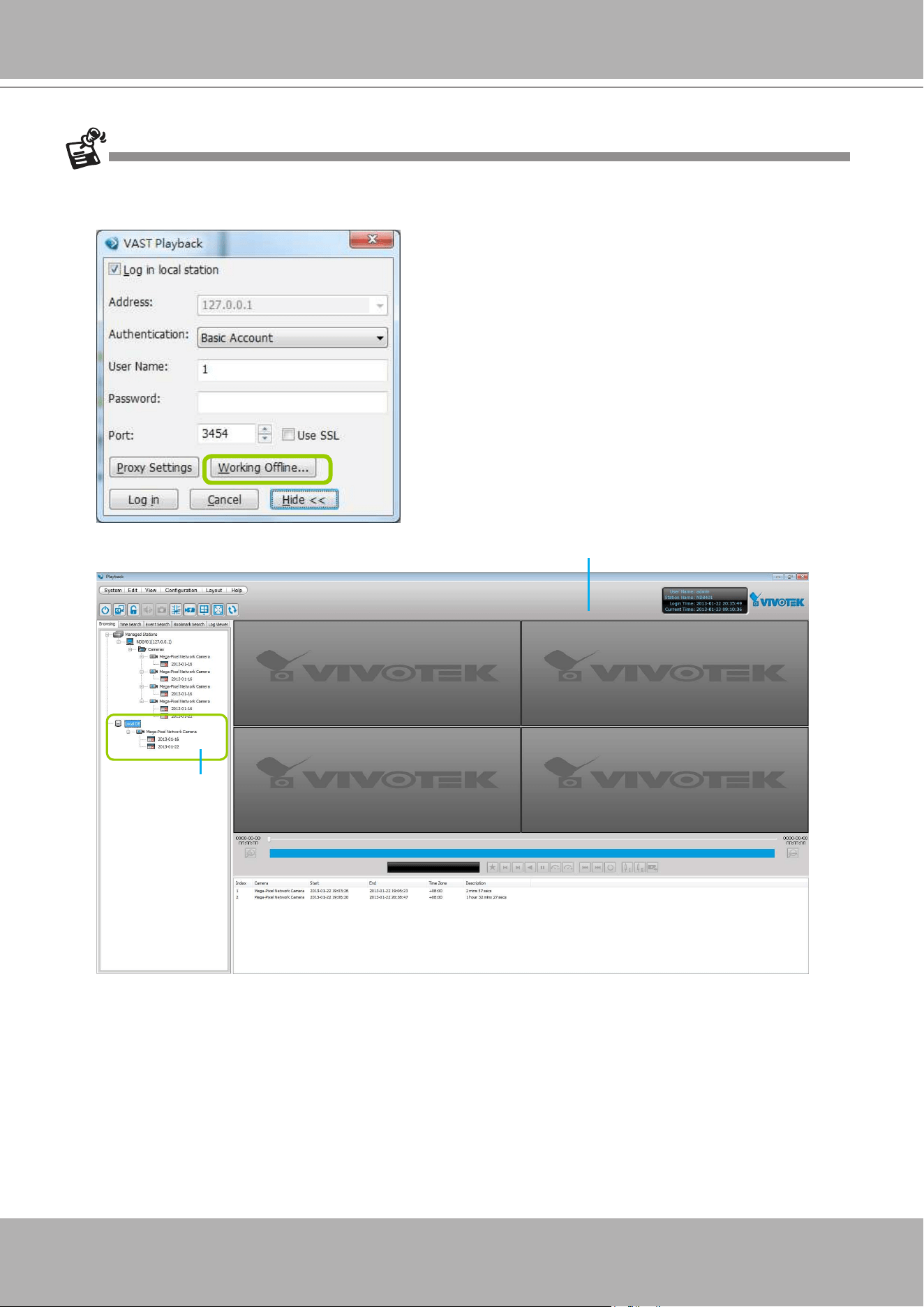
VIVOTEK - A Leading Provider of Multimedia Communication Solutions
User's Manual - 301
If you want to playback the backup les from the local database, you can also click
Working Ofine
in the Login
Window without the account information. The VAST Playback will launch as shown below.
You can upload
backup les
No user account information required
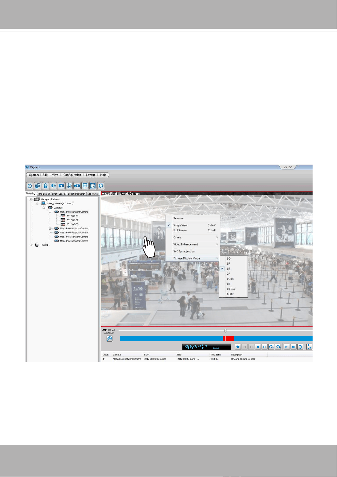
VIVOTEK - A Leading Provider of Multimedia Communication Solutions
302 - User's Manual
Model-specic Functions (FE Series Fisheye)
The VAST Playback program offers model-specific functions through a right-click menu. For
example, if you playback a video clip made from an FE8171V sheye camera, a right-click on
the playback screen will bring up the Display mode options. You can even exert mouse control
while playing a recorded video. You can zoom in, zoom out, and change the view angle as if you
are investigating a 3D scenario kept in a recorded point in time.
Note that ePTZ functions via the mouse control only takes place in a Regional view, e.g., the 1R
or 1O3R mode.
The
Display mode
options and
mouse control
methodologies are identical to those described on page
124 and the following pages.
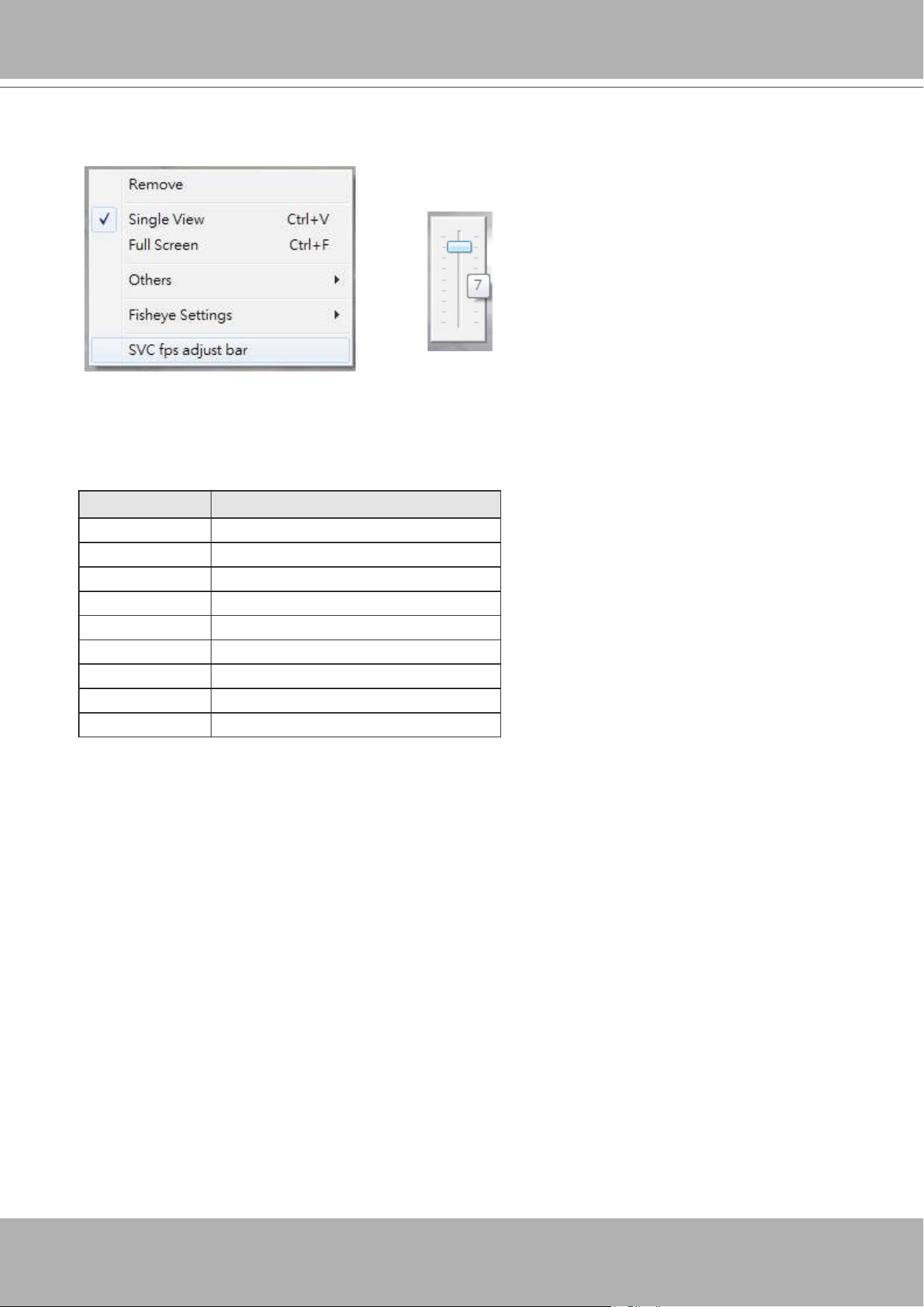
VIVOTEK - A Leading Provider of Multimedia Communication Solutions
User's Manual - 303
To congure the SVC-related feature:
1. Right-click on the playback window of an SVC-enabled camera. Select
SVC fps adjust bar
.
2. A slide bar will appear above the view cell. Click and drag the slide bar. A numeric indicator will display
the current selection. See below for the frame rates represented by the numeric indicator. Please refer
to page 102 for the introduction of this feature. Changing the SVC vaule takes immediate effect on the
number of frames per second shown with the video being played.
Indicator Frame rate per second (fps)
Maximum 30
7 26
6 22
5 18
4 12
3 8
2 4
1 1
Minimum 1/4
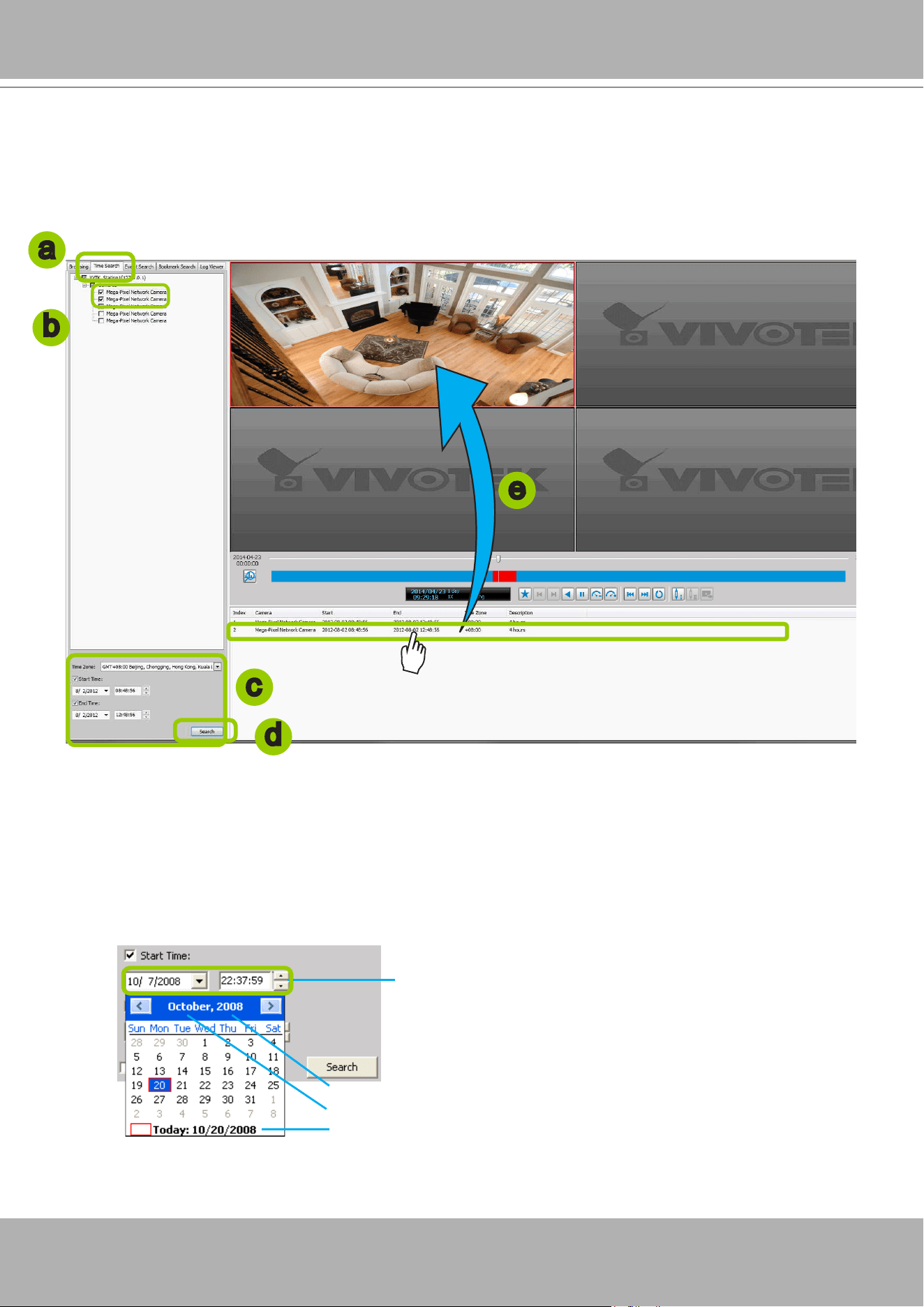
VIVOTEK - A Leading Provider of Multimedia Communication Solutions
304 - User's Manual
How to Search for a Video Clip in a Specic Period of time
Please follow the steps below to use
Time Search
function:
a. Open the
Time Search
page.
b. Select the target station(s)/device(s) that you want to search for video clips.
c. Specify the time span. You can choose to set up the start time only, the end time only, or both the
start time and end time. The search results will only include the video clips within the time span. If you
uncheck both the start time and end time, the search results will include all video clips recorded by the
selected device(s).
d. Click
Search
to start time search.
e. View the retrieved video clips.
Click here to move the focus to the current date
Click to select a year
Click to select a month from the drop-down list
You can manually enter a specic time.
a
c
e
d
b
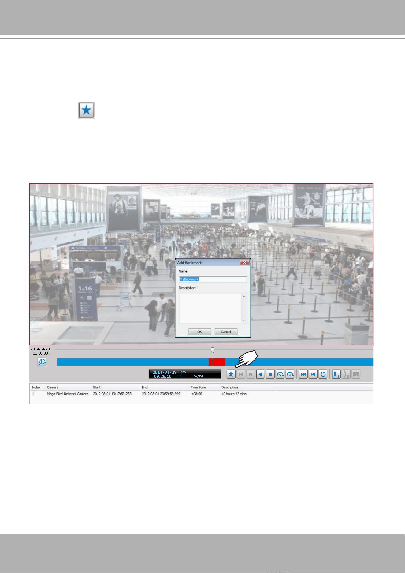
VIVOTEK - A Leading Provider of Multimedia Communication Solutions
User's Manual - 305
How to Add a Bookmark
Bookmark is a convenient tagging function that allow your to pinpoint and extract a 20-second video
clip from out of a video recording. When you see somehting of your interest while browsing through a
recorded video,
1. Click on the Bookmark button,
2. Enter a name for the bookmark, such as "thief spotted."
3. You may enter a short description in the Description eld. You may also search for the bookmarks you
created later on.
A bookmark comprises a video clip starting from 10 seconds of before and ends at 10 seconds after the
point in time you selected.
Please refer to page 281 for how to search for bookmarks.
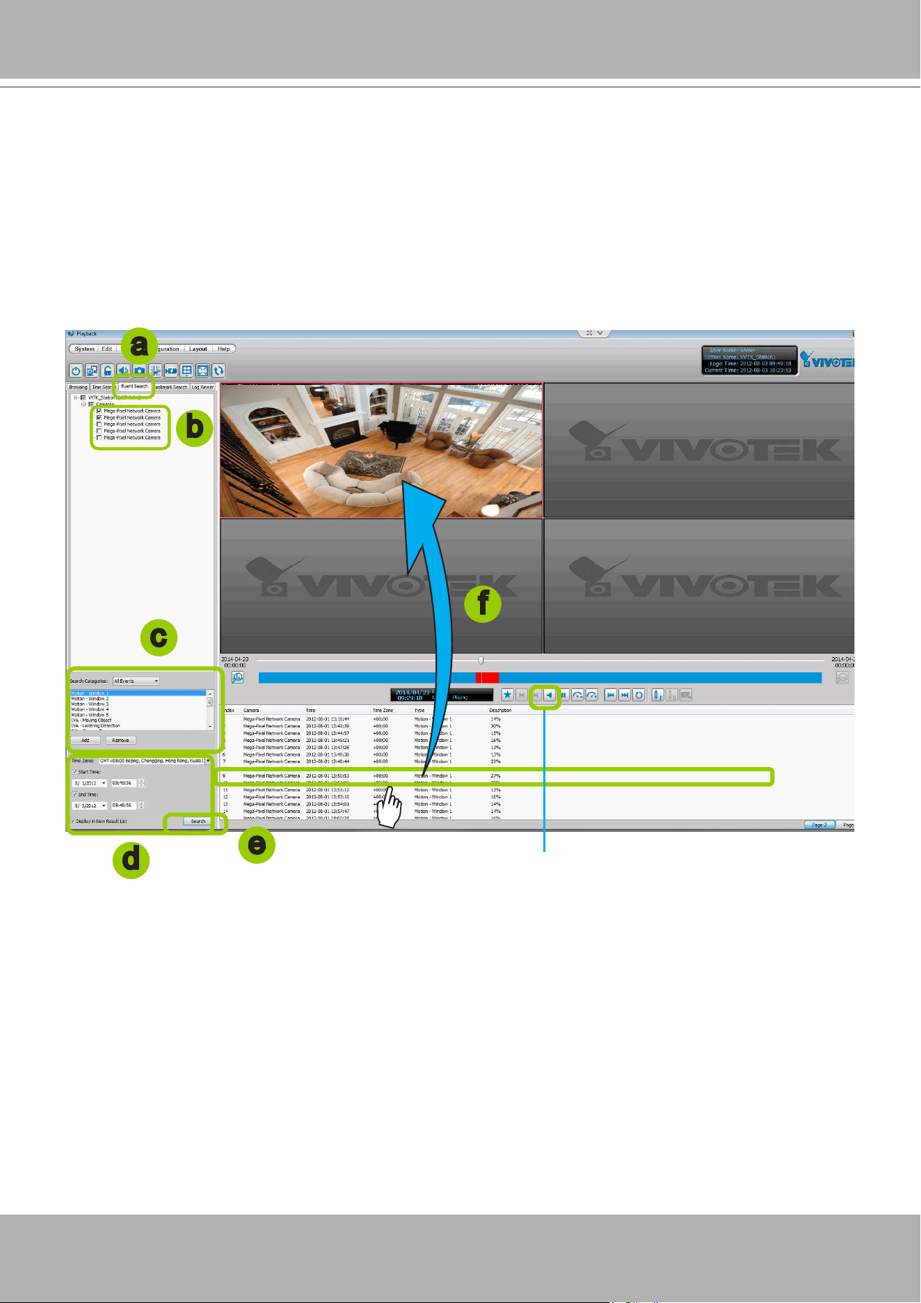
VIVOTEK - A Leading Provider of Multimedia Communication Solutions
306 - User's Manual
How to Search for Events
The VAST Playback program offers users an intuitive event search engine for retrieving video
clips from the database of recorded videos based on different search criteria such as motion,
IVA, or DI events.
Please follow the steps below to search for recorded events:
a. Open the
Event Search
page.
b. Select the target station(s)/device(s) that you want to search for events.
c. Specify the
Event Category
. For detailed information, please refer to
Select Event Category
on the
following page.
d. Specify the time span for event search. You can choose to set up the start time only, the end time
only, or both the start time and end time. The search results will only include the events within the time
span. If you uncheck both the start time and end time, the search results will include all events from
the selected device(s). Please refer to step c. on the previous page for detailed information.
e. Start event search. Please refer to page 310 for detailed information.
f. View the retrieved video clips.
Double-click
on it or
drag-and-drop
it to the video cell. It will playback
in repeat mode.
Note: The length of each video clip will depend on your settings of pre-event time & post-event time for
the recording storage. The default setting is
20 seconds
. For more infromation, please refer to page
187 for detailed information.
b
c
d
e
f
a
repeat mode
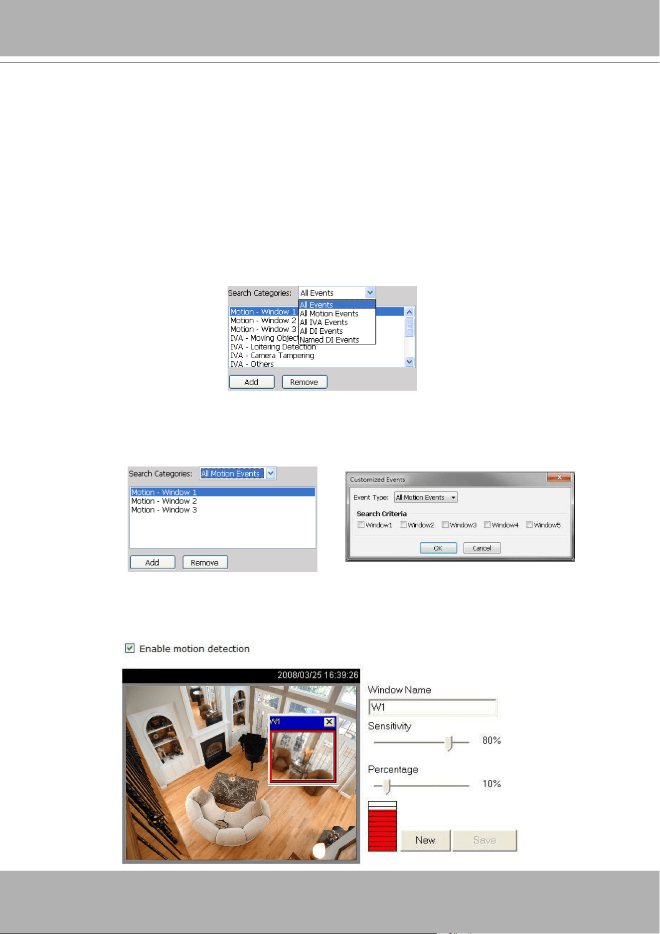
VIVOTEK - A Leading Provider of Multimedia Communication Solutions
User's Manual - 307
Select Event Category
The following introduces the event search categories:
All Events
,
All Motion Events
,
All
IVA events
,
All DI Events
,
Named DI Events, PIR, Tampering,
Tamperature, Video Loss/
Restore, IR Trigger/Normal, and P-PTZ
. You can also add or remove customized events from
the list.
Event Category- All Events
If you select the
All Events
category, all of the events including motion detection, digital input, and
intelligent video analysis, PIR, tamper detection, and tamperature alarm will be listed in the search
results. You can click
Add
or
Remove
to change the search criteria options.
Event Category- All Motion Events
If you select the
All Motion Events
category, all detected motion events will be included in the search.
You can click
Add
or
Remove
to change the search criteria options.
The parameters of the motion detection windows, such as motion percentage and the time of occurrence
are also recorded in the database of the server. If you wish to change the parameters of the motion
detection windows such as the position, size, detection sensibility, and motion percentage, please link to
the camera's Conguration page to modify the values.
Video(TCP-AV)
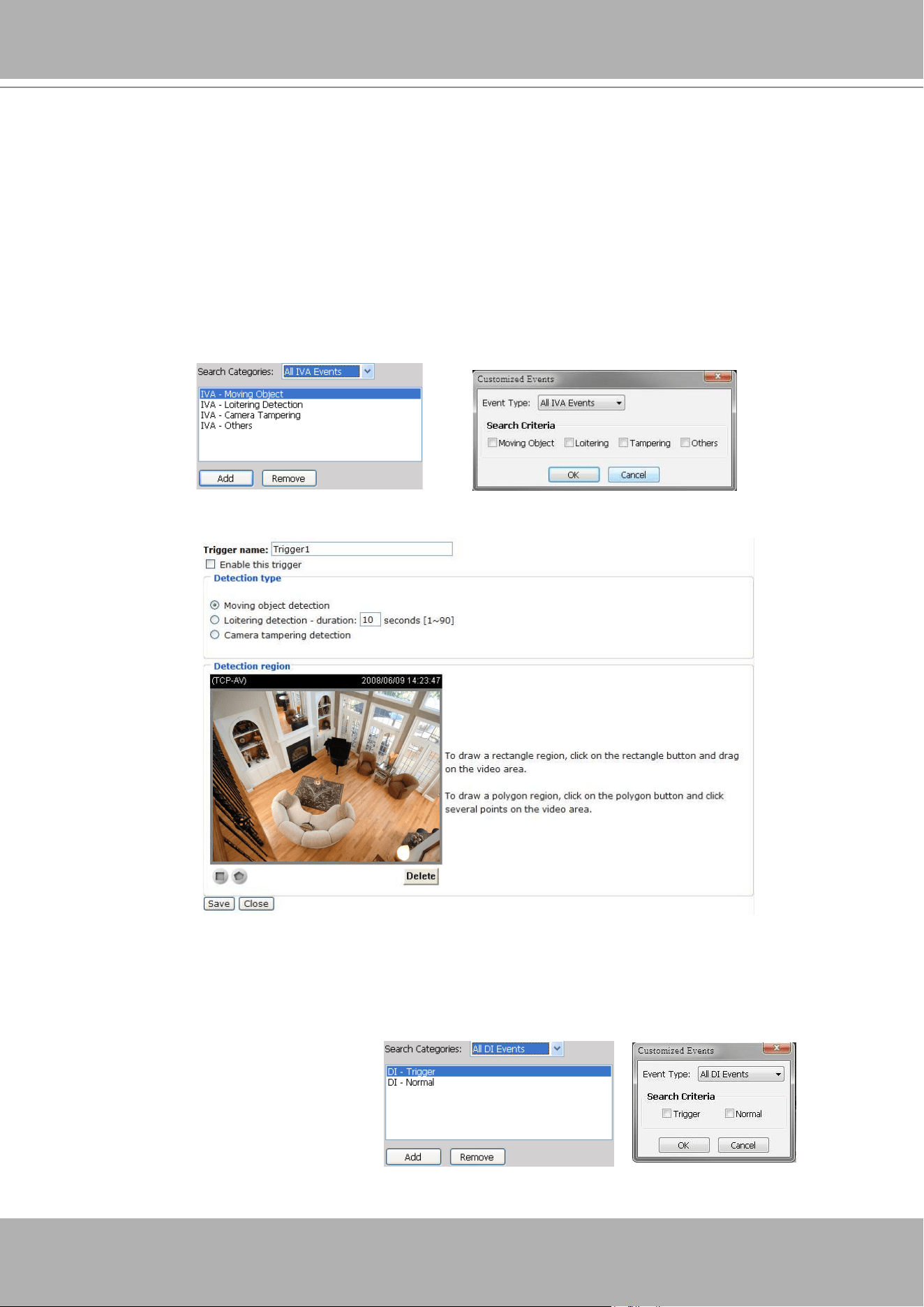
VIVOTEK - A Leading Provider of Multimedia Communication Solutions
308 - User's Manual
Event Category- All IVA events
If you select the
All IVA events
category, all detected IVA events will be included in the search. Cameras
with embedded intelligent video content analysis are capable of detecting IVA events such as moving
objects, loitering, and tamper detection.
The embedded video content analysis, superior to the conventional motion detection function, is capable
of distinguishing between creature’s motions, static backgrounds or natural movements such as swaying
trees, waves or sunsets to prevent false alarms from environmental noises.
With camera tamper detection, it can detect incidents such as camera redirection, blocking or defocusing
of cameras, or even spray-paint. Additionally, a suspicious object in the pre-dened detection region will
trigger alarms once the dwell time of the object is longer than the given time.
You can click
Add
or
Remove
to change the search criteria items.
If you want to change the parameters of IVA, such as the detection region, loitering duration, etc, please
link to the camera's Conguration page to modify the values.
Event Category- All DI Events
If you select
All DI Events
category, all triggered DI signals will be included in the search. The DI events
signify that there is a Digital-Input signal detected by the camera; its corresponding information such
as DI-Trigger or DI-Normal signal and the time of occurrence are also transmitted and recorded in the
database of the server.
You can click
Add
or
Remove
to change
the search criteria options.
For more information about DI/DO settings on the connected devices, please refer to page 159 for
detailed illustration.
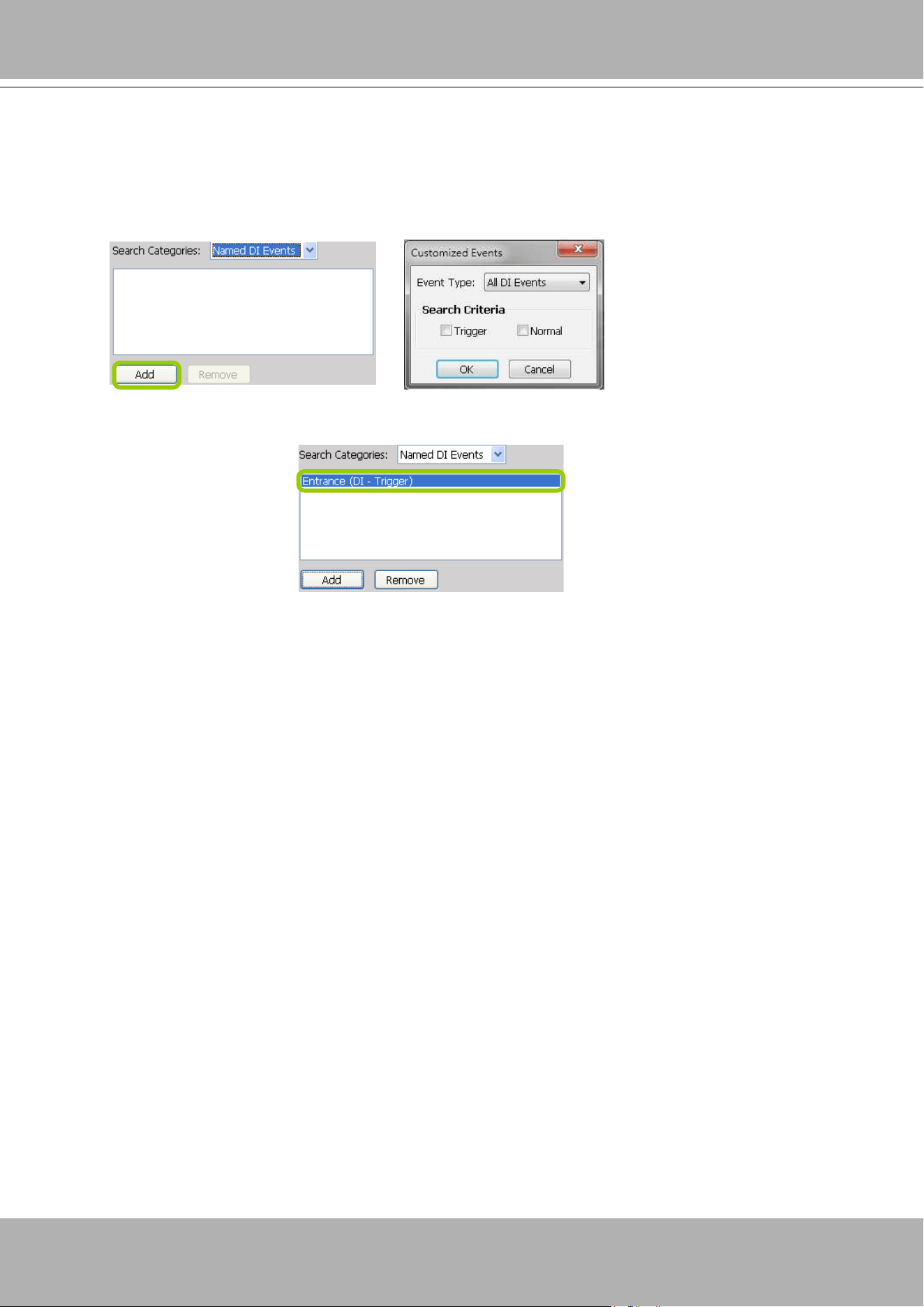
VIVOTEK - A Leading Provider of Multimedia Communication Solutions
User's Manual - 309
Event Category- Named DI Events
This category allows you to select only
Named DI Events
--the DI device which you have renamed in
the LiveClient. Please refer to Association Management on page 159 for more information about how to
rename DI device.
Click
OK
and ll in the name you want to search on the left window.
The new search criteria will be displayed in the search categories column as shown below.
You can click
Add
or
Remove
to change the search criteria options.
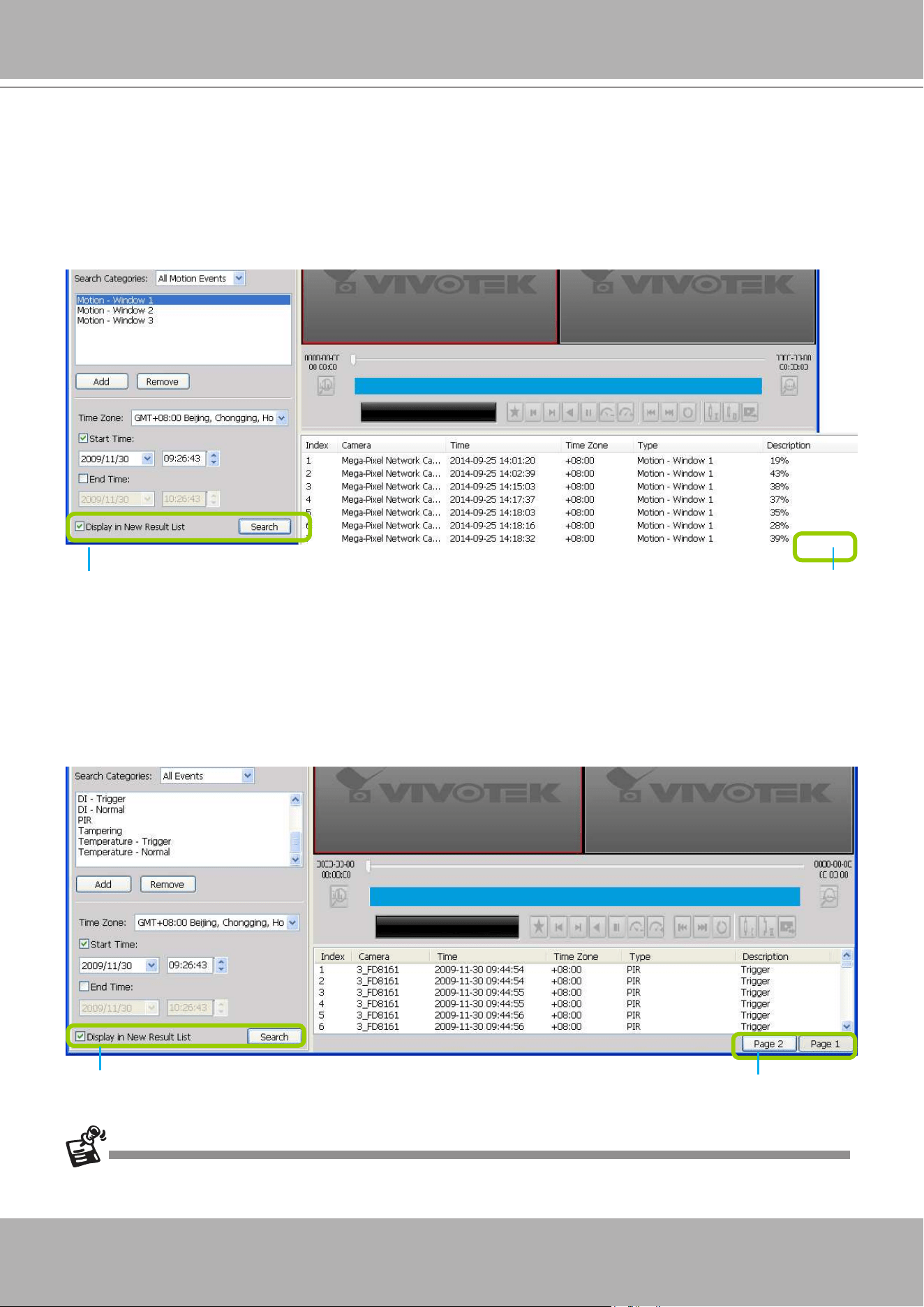
VIVOTEK - A Leading Provider of Multimedia Communication Solutions
310 - User's Manual
Start Event Search
After you specify all of the search criteria mentioned above, check/uncheck
Display in new result list
and click
Search
to begin event search.
If
Display in new result list
is unchecked, all search results will be displayed on the original event list
window as shown below.
In the above picture, The
Type
field in the search result page shows the event category, and the
Description
eld displays the motion
percentage
of the detection window. Please refer to page 307
for more information about Motion Events.
If you select
Display in new result list
and click
Search
, the search results will be displayed on a
new page as shown below. This allows you to place the search results of each search category on an
individual page. You can set up to 5 pages in the event list window.
Unchecked
Only one page
Checked
You can set up to 5 pages.
The P-PTZ event type refers to those triggered by the Auto Tracking actions.
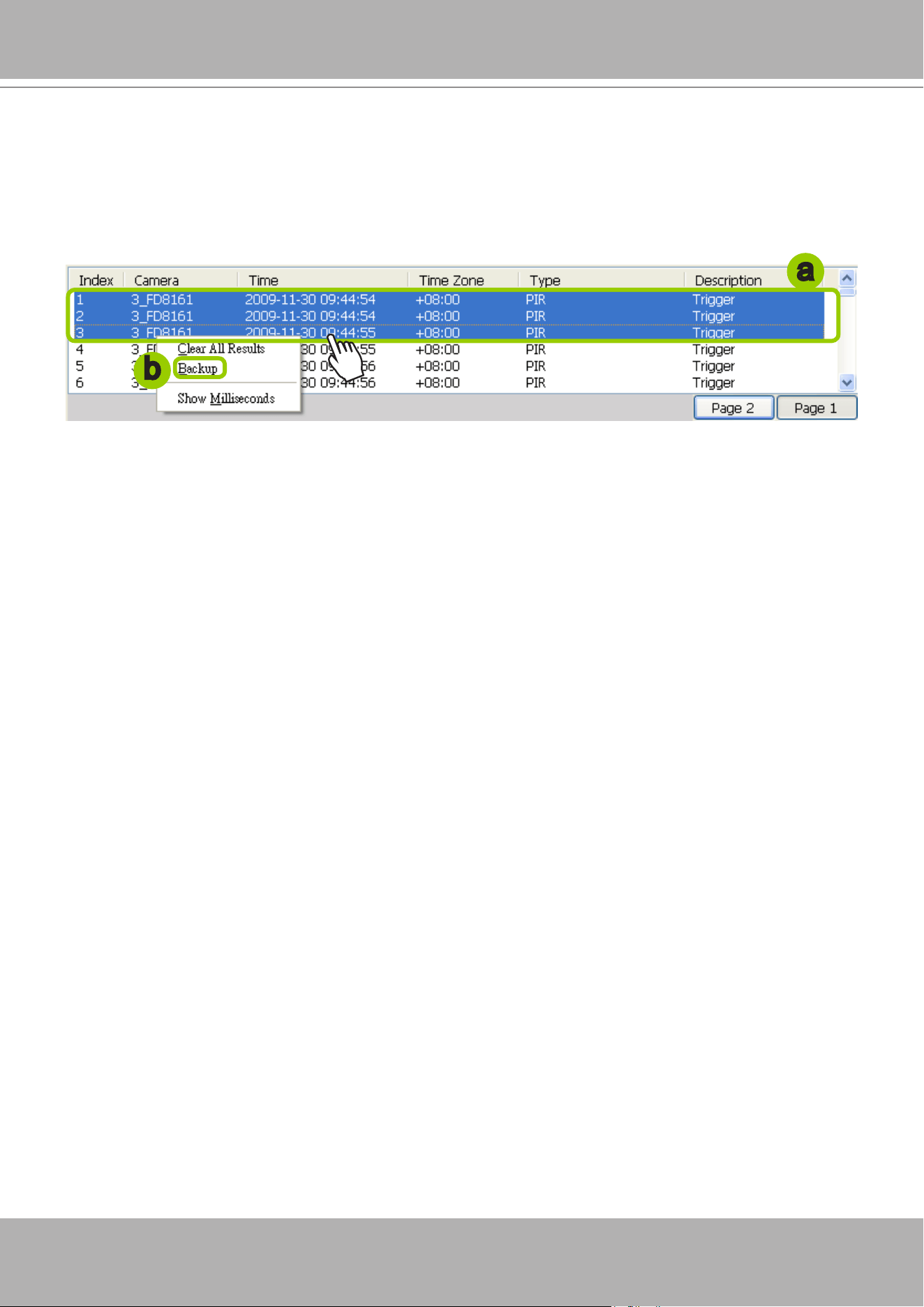
VIVOTEK - A Leading Provider of Multimedia Communication Solutions
User's Manual - 311
Backup the Event Videos
Please follow the steps below to backup the evnet videos on the results list:
a. Select the video clips you want to backup. You can select more than one video clip.
b.
Right-click
the selected video clips and click
Backup
.
c. A
Backup Settings
window will pop up. For more information about how to set up the Backup
Settings, please refer to page 298. For more information about how to view backup les, please refer
to page 300 for detailed illustration.
a
b
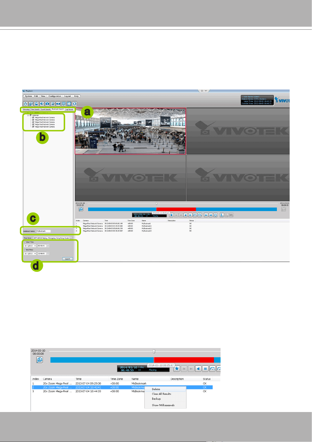
VIVOTEK - A Leading Provider of Multimedia Communication Solutions
312 - User's Manual
How to Search for a Bookmark
Please follow the steps below to use
Bookmark Search
function:
a. Click on the tabbed menu to open the
Bookmark Search
page.
b. Select the cameras which have video clips you have placed bookmarks on.
c. Enter the name of bookmark.
d. Specify a range of time during which the video streams were recorded and its points in time were
bookmarked.
Click
search
. You can then click on a bookmark to display the short video clip extracted from
within the recorded video.
To remove an existing bookmark, left-click to select an entry, and then right-click to display the
Delete button. Bookmarks will be indicated as "Invalid" if the videos where the bookmarks were
appended were erased, e.g., when the original recording was erased by cyclic recording.
a
c
d
b
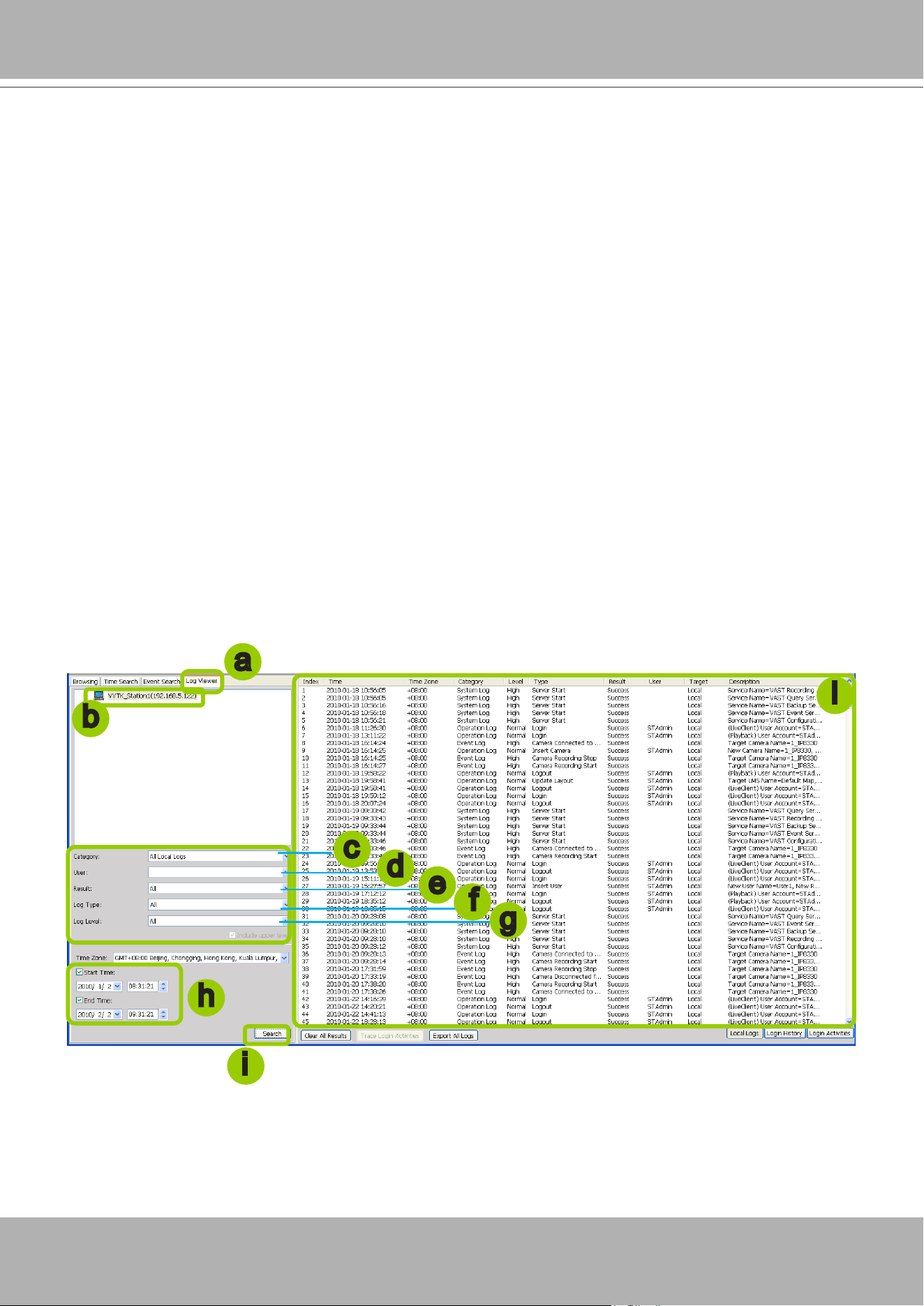
VIVOTEK - A Leading Provider of Multimedia Communication Solutions
User's Manual - 313
How to Search Logs
The VAST Playback program offers a convenient log engine for searching all local logs based
on different search criteria such as log category, log type, and log level. The search results will
be displayed in the log viewer window along with the detailed log history.
Please follow the steps below to search logs:
a. Open the
Log Viewer
page.
b. Select the target station where you want to search logs.
c. Specify the
Log Category
. For detailed information, please refer to
Select Log Category
on page 314.
d. Specify the
User Account
. If you have added other user accounts to the station, you can select one to
search its login history. For detailed information about user account, please refer to
How to Manage
User Accounts
on page 150.
e. Specify the
Search Result
. Select
All
to display all search results; select
Success
to display successful
log activities only; select
Fail
to display failed log activities only.
f.
Specify the
Log Type
. For detailed information, please refer to
Select Log Type
on page 314.
g. Specify the
Log Level
. For detailed information, please refer to
Select Log Level
on page 314.
h. Specify the search time span. You can check the start time only, the end time only, or both the start
time and end time. The search will only include the events within the time span. If you uncheck both
the start time and end time, the search will include all events saved by the server. Please refer to page
304 for detailed information.
i. Start the log search and the results will be displayed on the log list window.
a
b
c
h
e
d
i
i
f
g

VIVOTEK - A Leading Provider of Multimedia Communication Solutions
314 - User's Manual
Select Log Category/Log Type/Log Level
The following table shows the breakdown of log category, level, and type. The search results will
be different according to your selections.
Log Categories Log Levels Log Types
Operation Log
Normal
Login / Logout
Insert User
Update User Name
Update User Password
Update User Privilege
Delete User
Insert Station
Update Station Information
Update Station Name
Delete Station
Insert Camera
Update Camera Information
Delete Camera
Set Recording Group
Insert Recording Schedule / Update Recording Schedule / Delete Recording
Schedule
Insert Event Management / Update Event Management / Delete Event
Management
Insert Recording Group / Update Recording Group / Delete Recording Group
Insert Recording Path / Update Recording Path / Delete Recording Path
Insert Camera to the Recording Group
Update Camera information in the Recording Group
Delete Camera from the Recording Group
Move Recording Path
Move Camera to another Recording Group
Insert Layout / Update Layout / Delete Layout
Set Digital Output
Update Scheduled Backup
Update Server Port
Set Proxy Server
Set UPNP
Set DDNS Server
Create Directory / Rename Directory / Delete Directory
Insert SMTP Server / Update SMTP Server / Delete SMTP Server
Insert Network Storage Device / Update Network Storage Device / Delete Network
Storage Device
Set GSM Modem
Set DI/DO Rename
Set Relay Settings
Update License Information
Update Web Access Information
Insert Matrix Recipient / Insert Matrix Recipient Information / Delete Matrix
Recipient
High
Manually Begin Recording
Manually Stop Recording
Low
Camera PTZ, Iris, Focus, Pan, Patrol Control
Click on Image
Select Preset Location
System Log
High
Server Start / Server Stop
Trial Expired
Key Dongle Lost
Virtual Memory Low
Network Lost / Storage lost
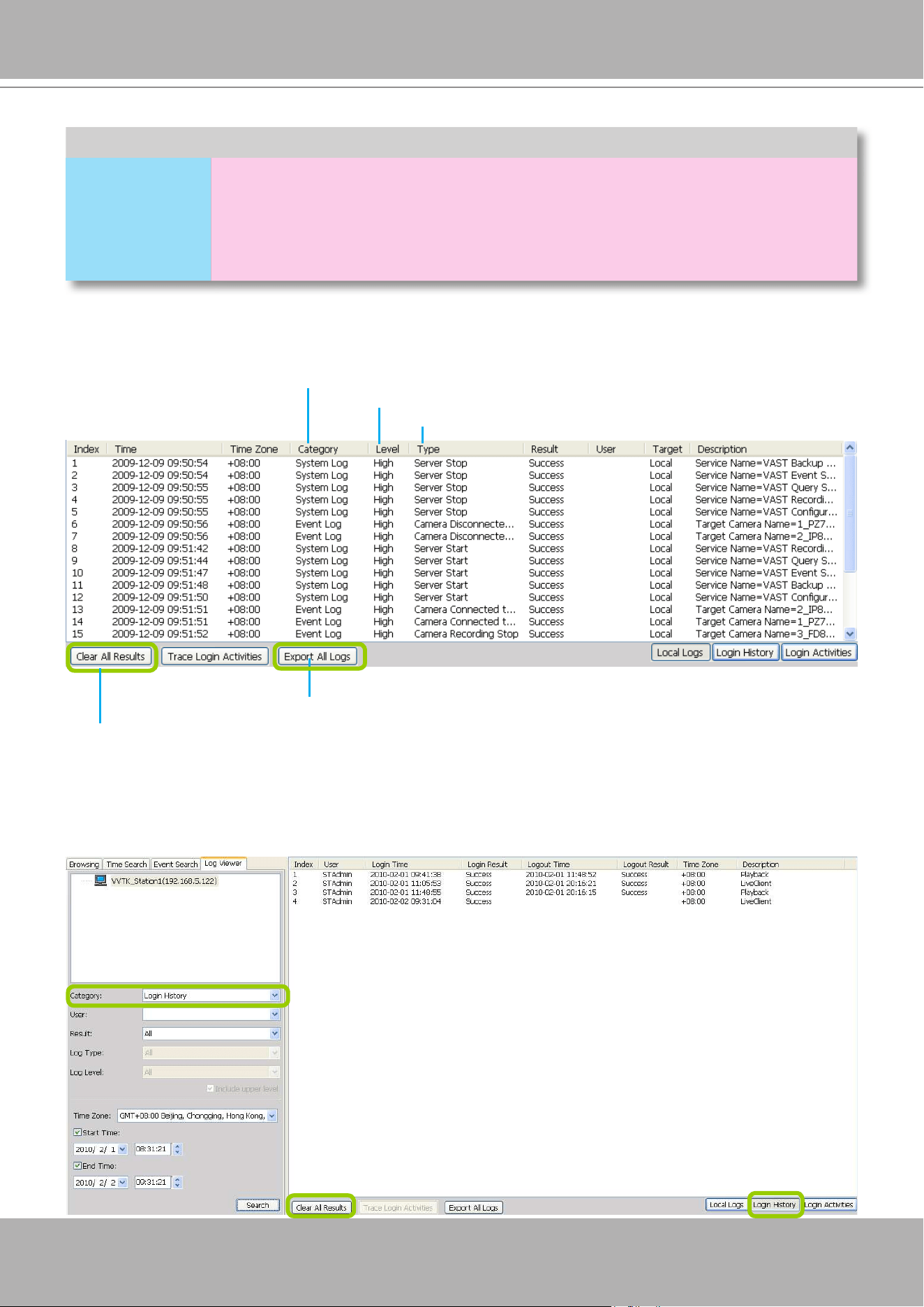
VIVOTEK - A Leading Provider of Multimedia Communication Solutions
User's Manual - 315
Search All Local Logs
Search Login History
Select
Login History
from the log category eld and click the
Search
button below, the search results,
including all login logs, will be displayed on the Login History page.
Log Categories Log Levels Log Types
Event Log
High
Camera Disconnected from the Server / Camera Connected to the Server
Parent Station Connection Lost / Parent Station Connection Restore
Sub-station Disconnected / Sub-station Connected
Camera Recording Start / Camera Recording Stop
Start Scheduled Backup / Stop Scheduled Backup
Event Trigger
Log Level
Log Category
Log Type
Click to remove all search results from the list
Click to export all search results from the list
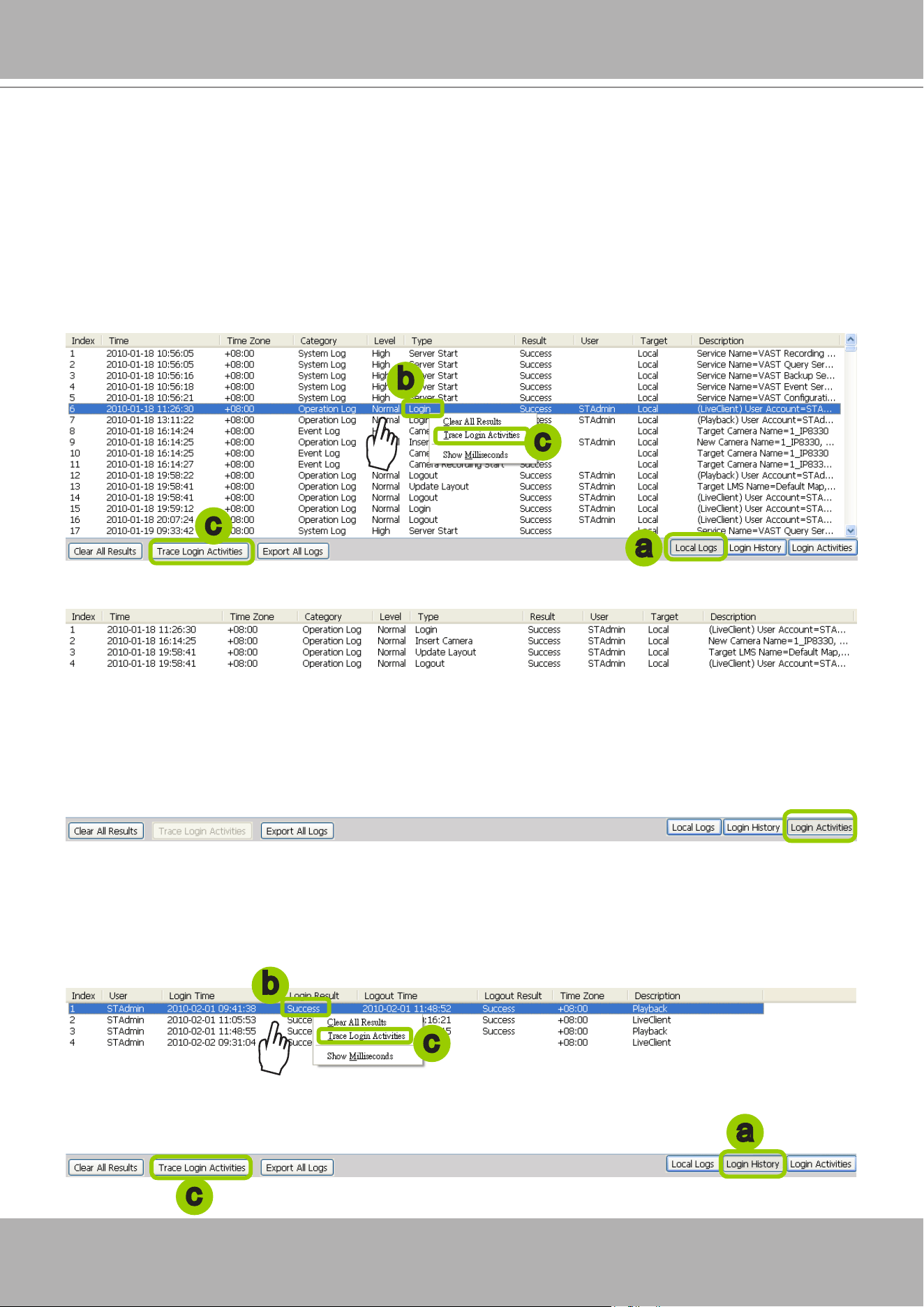
VIVOTEK - A Leading Provider of Multimedia Communication Solutions
316 - User's Manual
Search Login Activities
This function allows you to search the operations the user performed during the login period of time. You
can search for login activities on the Local Logs or Login History page.
Search Login Activities on the Local Logs page:
a. Click on the
Local Logs
page.
b. Select a login/logout option from the list.
c. Click
Trace Login Activities
(or you can
right-click
the selected login/logout option on the list, then
click
Trace Login Activities
).
d. The search results of the login activities will be displayed on the Login Activities page as shown below.
Search Login Activities on the Login History page:
a. Click on the
Login History
page.
b. Select a login/logout option from the list.
c. Click
Trace Login Activities
(or you can
right-click
the selected login/logout item on the list and
click
Trace Login Activities
).
a
b
c
c
a
b
c
c
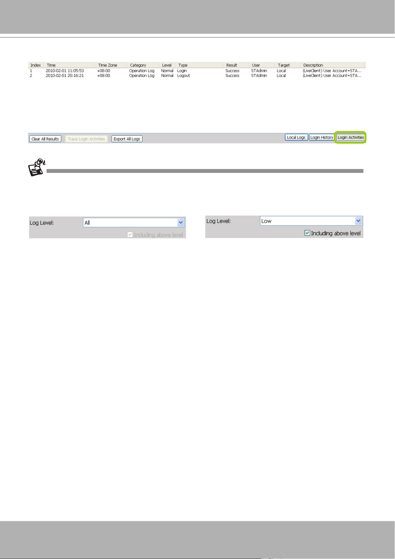
VIVOTEK - A Leading Provider of Multimedia Communication Solutions
User's Manual - 317
d. The search results of the login activities will be displayed on the Login Activities page as shown below.
When you select
All
in the
Log Level
eld, the search results will include all log levels. If you select Low in the
Log Level
eld and select
Including above level
as shown in the picture on the left below, the search results
will include all levels of logs. But if you select
Normal
in the
Log Level
eld and select
Including above level
as
shown in the picture on the right below, the search results will only include
Normal-level
and
High-level
logs.
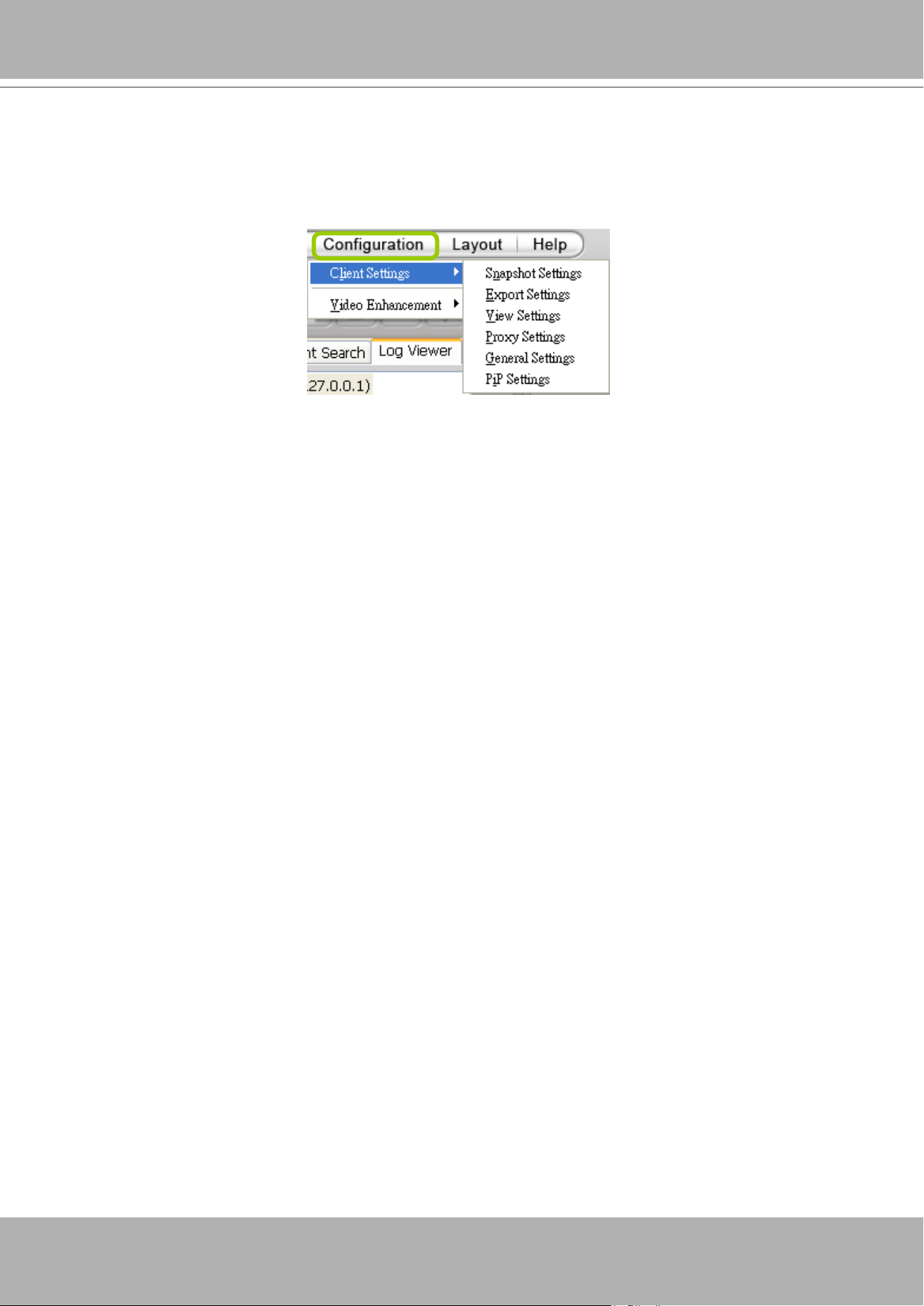
VIVOTEK - A Leading Provider of Multimedia Communication Solutions
318 - User's Manual
How to Congure Client Settings
On Client Settings, you can congure Snapshot Settings, Export Settings, View Settings, Proxy
Settings, and General Settings. It allows you to save snapshots and media files on the local
computer.
Snapshot Settings
When you play a recorded video, VAST Playback also allows you to take snapshots. For
detailed information about
Snapshot Settings
, please refer to page 229.
Export Settings
When you playback a recorded video, the VAST server allows you to export part of the recorded
video in EXE, 3GP, or AVI format to your local computer. Before exporting a media le, please
set up Export Settings first. For detailed information about how to set up EXE, 3GP, and AVI
Export Settings
, please refer to Record Settings on page 231.
The default exporting path is: C:\ProgramData\VIVOTEK Inc\VAST\Client\PlayBack\Export
Limitations
1. The size of exported footage depends on the file size limitation. When the limitation is
reached, les will be concluded regardless of the length of your selection.
2. The Export button will not be available when there is another exporting task.
3. If the time settings on camera and VAST server are inconsistent, the export task will generate
les of unexpected length.
4. The minimum export length is 1 minute. The maximum is 150 minutes. However, due to the
embedded limitation, the approximate max. le size is 3.7GB.
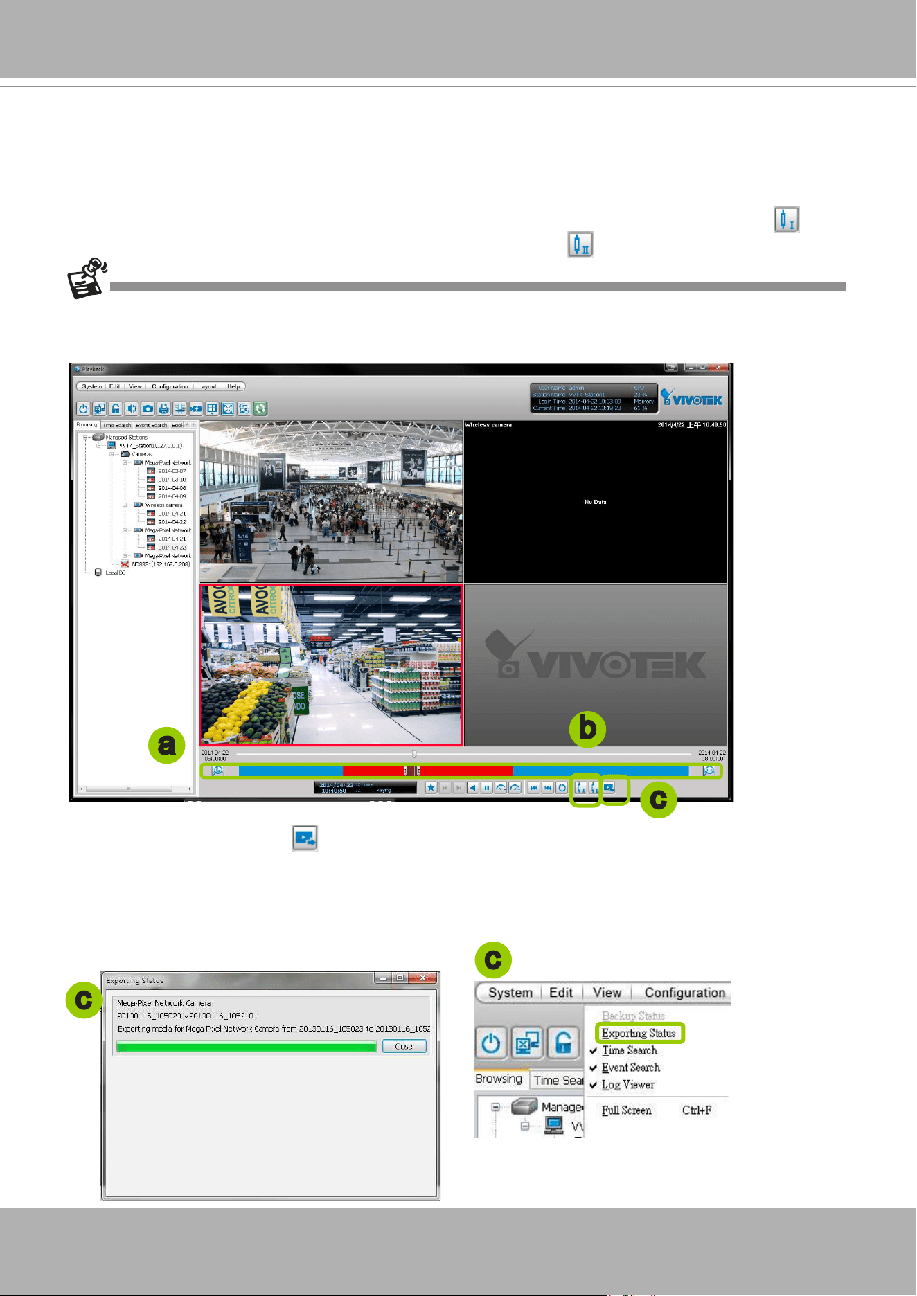
VIVOTEK - A Leading Provider of Multimedia Communication Solutions
User's Manual - 319
Export an EXE/3GP/AVI File
Please follow the steps below to convert part of an EXE/3GP/AVI le of recorded video:
a. Playback a video clip from which you want to export a media le.
b. Set a period of time. Move the timeline slider bar to the desired start time and click Marker I . Move
the timeline slider bar to the desired end time and click Marker II .
c. Click Export EXE/3GP/AVI , the server will start to export the data and popup a window showing
the exporting status. If you close the status window, you can also open it again by clicking
View >
Exporting Status
.
d. When the export is complete, you will see an information dialog. The exported data will be restored in
the preset storage folder on your local computer (C:\ProgramData\Documents\VIVOTEK Inc\VAST\
Client\PlayBack\Export).
a
b
c
c
c
Currently exporting video les from the NVR series is not supported.
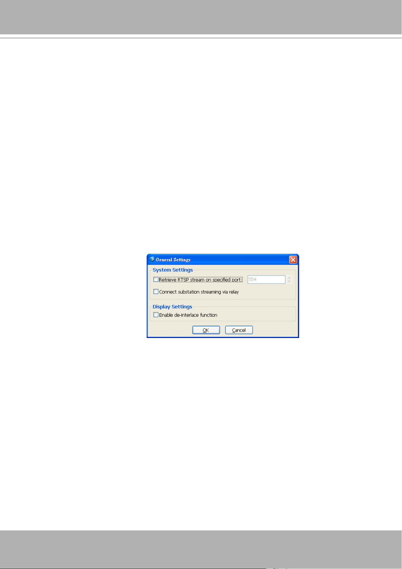
VIVOTEK - A Leading Provider of Multimedia Communication Solutions
320 - User's Manual
View Settings
This section allows you to set up the display mode of video cell. For detailed information about
View Settings
, please refer to page 237.
Proxy Settings
Please refer to page 255 for detailed illustration.
General Settings
System Settings
Please refer to page 240 for detailed information.
Display Settings
Enable de-interlace function: Select this option if your connected device does not support de-interlace
function. For example: VS7100.
How to Congure Video Enhancement
The Playback also allows you to enable post-image enhancement and defog for video viewing.
Please refer to page 259 for detailed information.
How to Search for a Device on the Hierarchical Management Tree
The Playback also allows you to conveniently search for an inserted device. Please refer to
page 264 for detailed information.
How to Print a Video Image
The Playback also allows you print out an image of live video. Please refer to page 265 for
detailed information.
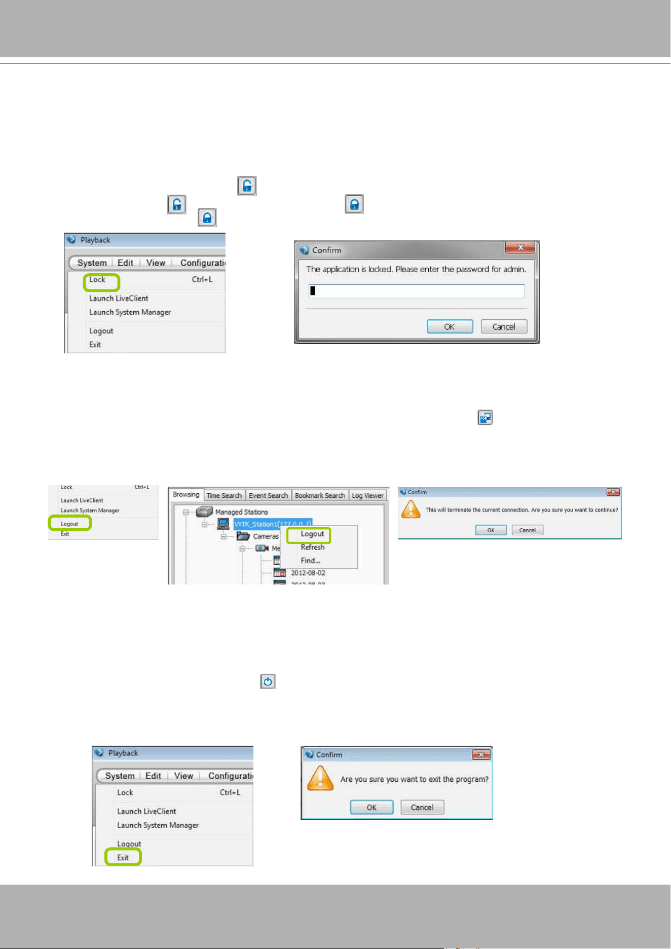
VIVOTEK - A Leading Provider of Multimedia Communication Solutions
User's Manual - 321
How to Lock VAST Playback for Security Concerns
If you happen to be away from your computer, for security reasons, we suggest you lock the
program. When VAST Playback is locked, the user must enter the correct password to unlock
and access the program again.
To lock Playback, click
Unlock
on the quick access bar or click
System > Lock
on the system
menu. The
Unlock
icon will then turn into
Lock
.
To unlock Playback, click
and enter the correct password in the popup window.
How to Log out from the VAST Server
To log out from the current server, click the station and click
Logout
on the quick access
bar or click
System > Logout
on the menu bar. You can also
right-click
the station and click
Logout
. A conrmation window will pop up. Click
OK
to conrm or
Cancel
to return to the VAST
Playback window.
How to Exit VAST Playback
To exit VAST Playback, click
Exit
on the quick access bar or click
System > Exit
on the
menu bar. A confirmation window will pop up. Click
OK
to confirm or
Cancel
to return to the
VAST Playback window. When you exit the program, your user account will be automatically
logged out from the current server.
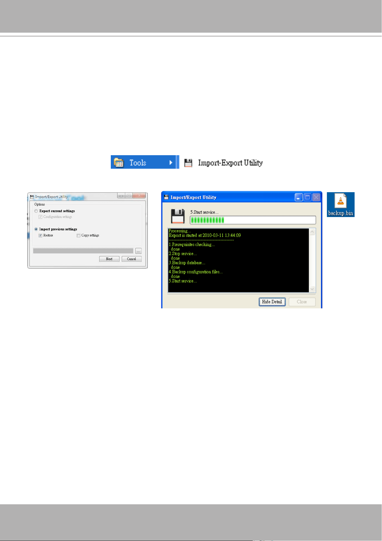
VIVOTEK - A Leading Provider of Multimedia Communication Solutions
322 - User's Manual
Import and Export Utility
VAST supports import and export utility for user to keep record of all server settings. You can
use the export le to copy the conguration on another host.
Export Utility
Please follow the steps below to export the server settings:
a. Under Microsoft Windows, choose "
Start > All Programs > VIVOTEK Inc > VAST > Tools > Import-
export Utility.
"
b. The
Import/Export Utility
window will pop up. Click
Export
and select a target folder. The system will
start to export a .bin le.
Import Utility
Please follow the steps below to import the server settings:
a. Under Microsoft Windows, choose "
Start > All Programs > VIVOTEK Inc > VAST > Tools > Import-
export Utility.
"
b. The
Import/Export Utility
window will pop up. Click
Import
and select the export le. The system will
start to import the le.
You should then select the
Restore
or
Copy
settings options.
Restore
: If this is selected, the VAST server GUID will also be restored. This option applies when
you need to restore as crashed server.
Copy Settings
: This applies you use the exported prole to duplicate your conguration to mul-
tiple computers. A new server GUID will be generated.
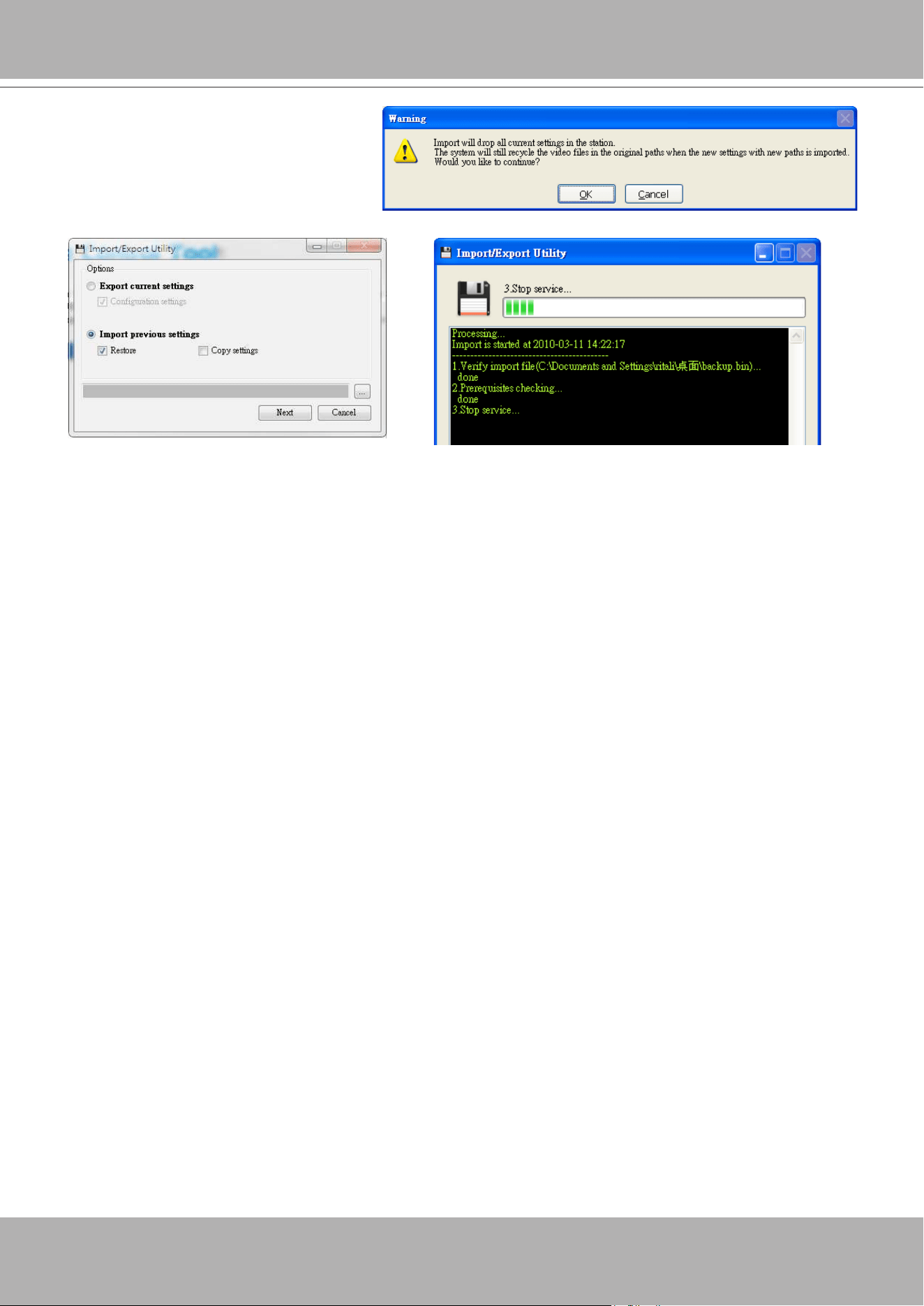
VIVOTEK - A Leading Provider of Multimedia Communication Solutions
User's Manual - 323
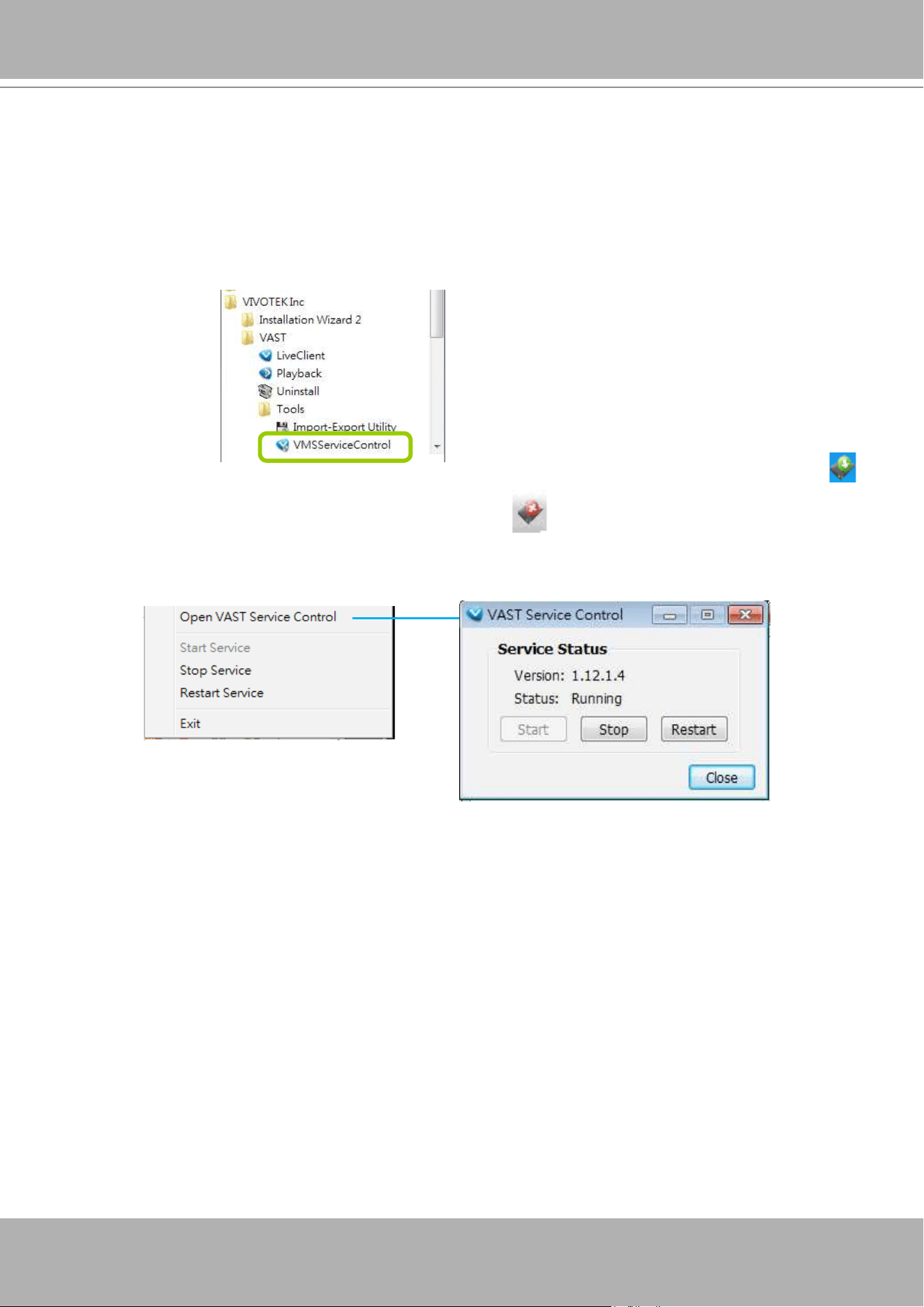
VIVOTEK - A Leading Provider of Multimedia Communication Solutions
324 - User's Manual
VAST Service Control Tool
VAST service control tool is a tool for server control and for user to be aware of the VAST Server status.
It starts up as Windows OS startup.
Under Microsoft Windows, choose "
Start > All Programs > VIVOTEK Inc > VAST > Tools >
VMServiceControl.
"
You may also nd it in the system tray icon of the tool bar, which indicates that the service is running:
It shows a disconnection icon when the service is stopped:
A menu for the service control tool will pop up when you
right-click
on the icon:
Here you can manually start, stop and restart the service.
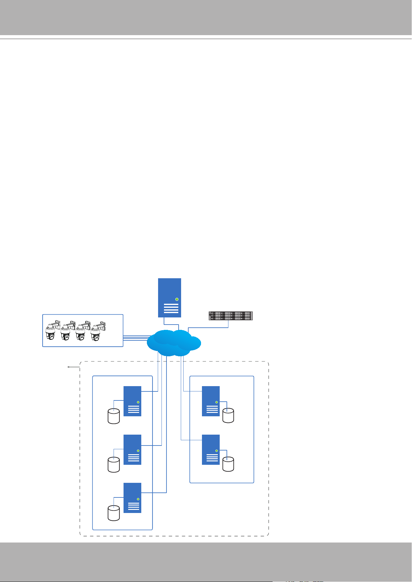
VIVOTEK - A Leading Provider of Multimedia Communication Solutions
User's Manual - 325
Appendix A Failover Server Conguration
VAST servers can be congured into two groups: Active and Redundant. The Active group
performs daily recording and monitoring tasks, while the Redundant group acts as the standby
servers. In the event of server failures, the Redundant group becomes active, and takes over
the recording task.
The Redundant server group conguration consists of the following:
1. One VAST server designated as the
CMS
(Central Management server) VAST central
management server.
2. At least one VAST server in the
Active
group.
3. At least one VAST server in the
Redundant
group.
4. Gb/s network or higher-speed connection among the servers. All Active and Redundant
groups can reside in different subnets, provided that static IPs are congured for these
servers.
Active VAST servers Redundant VAST servers
CMS VAST
Active Group Redundant Group
Node 1
Node 2
Node 1
Node 2
Node 3
External storage /
NAS
Network Cameras
LAN
. . . . .
Server Group
IMPORTANT:
For a Redundant server conguration, you must rst enlist VAST servers in the
Sites
conguration page before conguring the Redundant server groups. See the
Sites
conguration page.

VIVOTEK - A Leading Provider of Multimedia Communication Solutions
326 - User's Manual
Below are the denitions of server roles:
1.
CMS
VAST server: The main access portal for the conguration.
1-1. CMS server is where the
Failover
conguration takes place.
1-2. CMS continuously polls to check the hearbeats to monitor the statuses of all Active
and Redundant servers.
1-3. CMS regularly backs up the congurations on Active servers.
1-4. CMS assigns redundant server(s) to the takeover of a failed Active server.
1-5. In a Redundant server conguration, the CMS is supposed to be up and running at
all time. If the CMS server fails, the server failover and failback operation will not
take place. It is therefore preferrable to install the CMS server at a high up-time
environment, such as on a VMWare conguration.
2.
Active
servers: Active VAST servers are the work horses that perform recording and
monitoring tasks.
3.
Redundant
servers: The Redundant servers are actually active-standbys. They participate
to continue video recording in the event of active server failures. It is recommended for the
Redundant server to have an equivalent or higher processing power than the Active servers.
The same applies for the storage volume and write performance.
Note that you cannot congure a Redundant server by opening a local console.
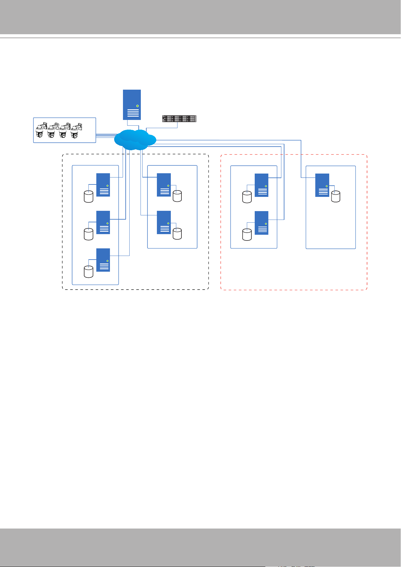
VIVOTEK - A Leading Provider of Multimedia Communication Solutions
User's Manual - 327
Multiple Active and Redundant groups can be created.
Active VAST servers Redundant VAST servers
CMS VAST
Active Group Redundant Group
Node 1
Node 2
Node 1
Node 2
Node 3
External storage /
NAS
Network Cameras
. . . . .
Server Group 1
Active VAST servers Redundant VAST servers
Active Group Redundant Group
Node 1
Node 1
Node 2
Server Group 2
LAN
Each Redundant server can serve as the backup for ONE Active server. Depending on
the number of the Active and Redundant servers, if the number of failed servers exceeds
the number of Redundant servers, the failover will be abandoned. For example, if 2 Active
servers failed, and there is only 1 Redundant server available, the second Active server that
failed will be abandoned.
The conditions during the failover are illustrated below:
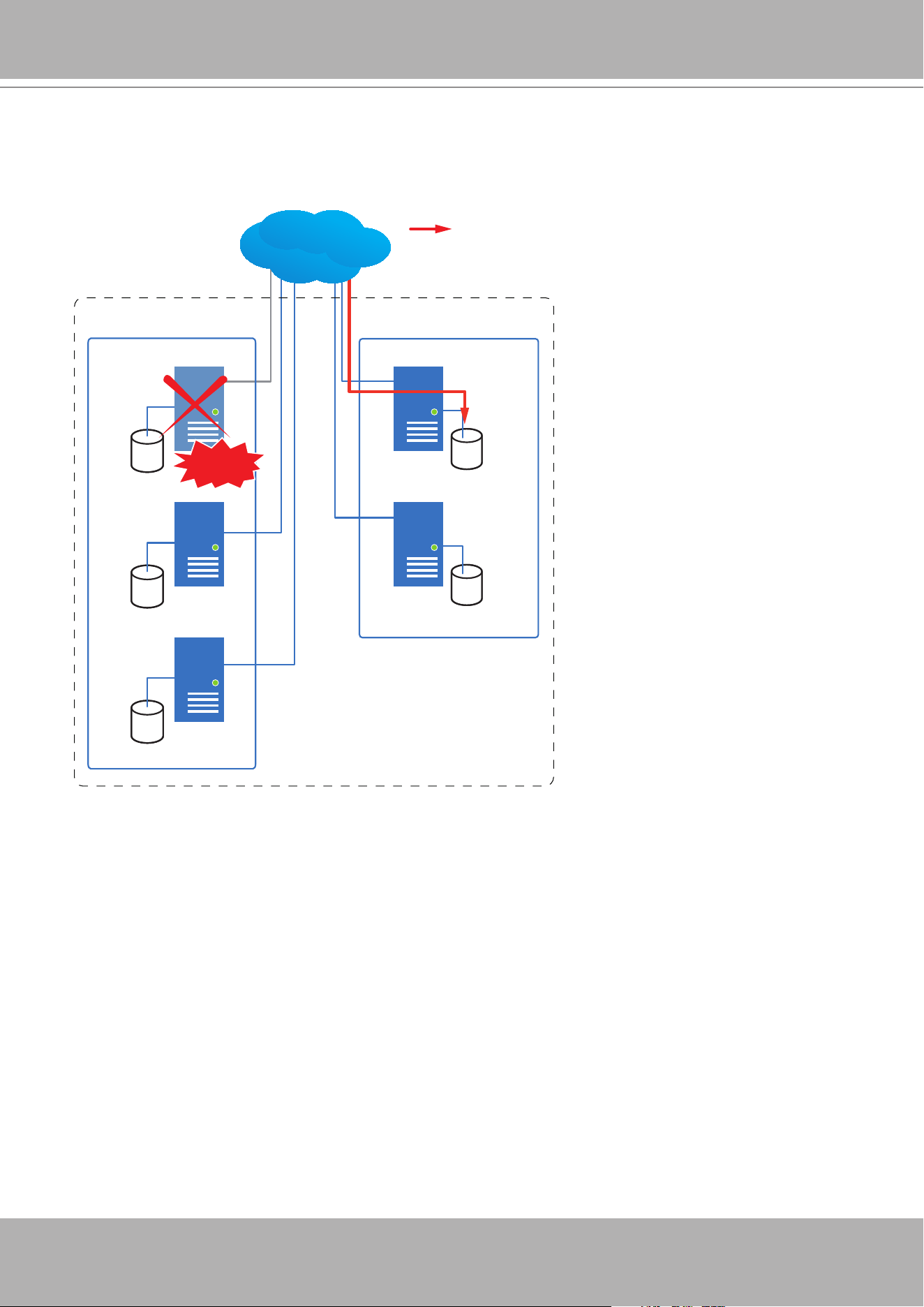
VIVOTEK - A Leading Provider of Multimedia Communication Solutions
328 - User's Manual
In the event of a server failover, a VAST server in the Redundant group takes over the recording
task. Note that depending on the network environment, the takeover can take up to 5 minutes.
Active VAST servers Redundant VAST servers
Active Group Redundant Group
Node 1
Node 2
Node 1
Node 2
Node 3
Server Group
Recording
LAN
Failed!
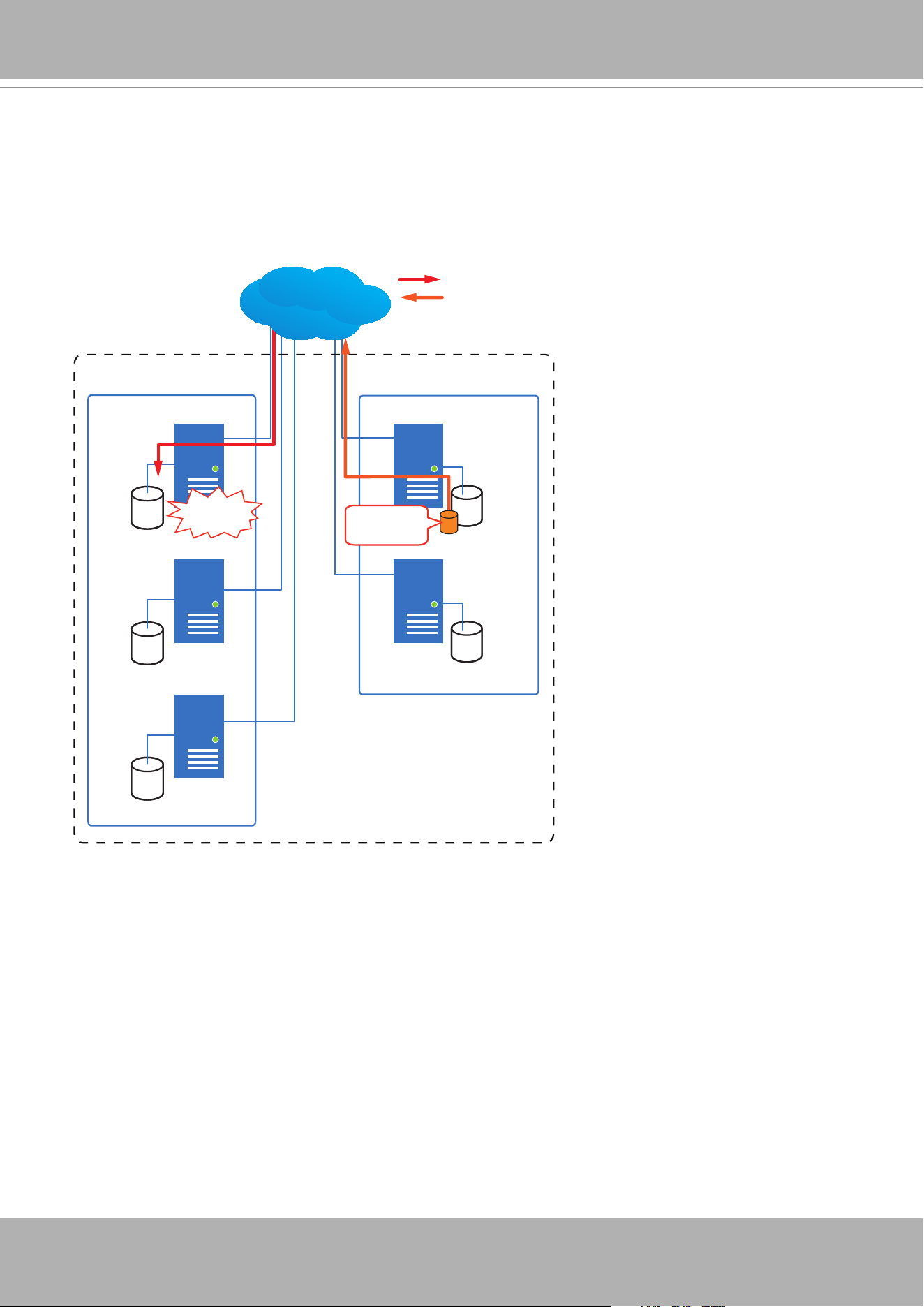
VIVOTEK - A Leading Provider of Multimedia Communication Solutions
User's Manual - 329
Once the server in the Active group is restored to normal operation, and a CMS server requests
for the recordings and data occurred during the time the active server failed, the requests will
be fullled by a shared volume on the redundant server. Due to the concerns with network
bandwidth and processing power, the restored active server does not synchronize its recording
pool with that on the redundant server.
Active VAST servers Redundant VAST servers
Active Group Redundant Group
Node 1
Node 2
Node 1
Node 2
Node 3
Server Group
Recovered!
Shared
Volume
LAN
Recording
Playback & Search
The recovery path should be available in the network neighborhood, with a name that looks like
the following: ActiveServer1_91AAF3D06B6C47_\RecGroup1.
If an Active server has 3 recording groups, then each Redundant server will have 3 recording
paths accordingly.
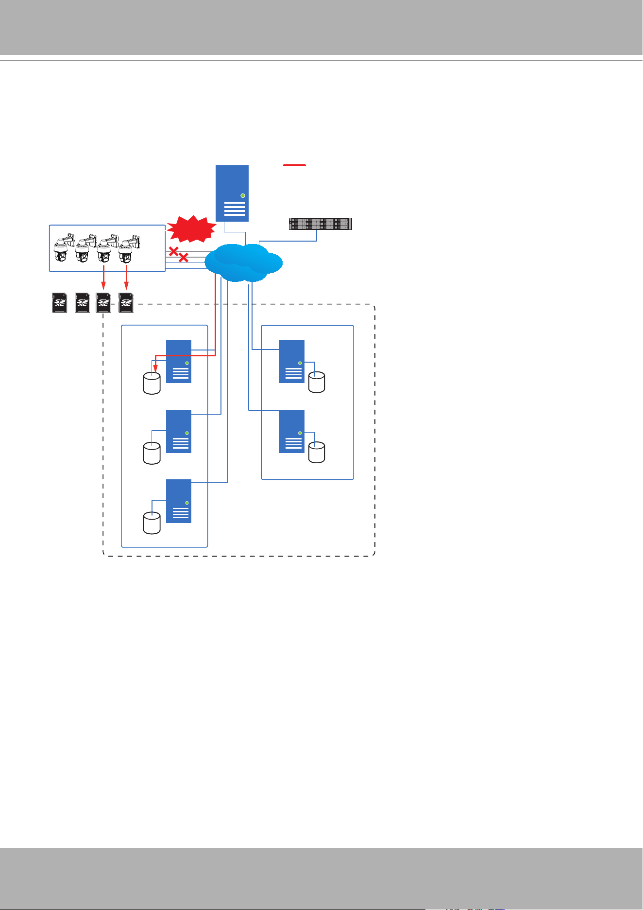
VIVOTEK - A Leading Provider of Multimedia Communication Solutions
330 - User's Manual
In terms of network failure, the VAST2 conguration supports Seamless Recording. For cameras
equipped with an SD card, video is recorded to the SD cards in the event of network failure. Of
course, the camera must be powered by a secondary power source, such as a DC 12V input. In
cases such as the only PoE switch or PoE mid-span fails, power is lost.
Active VAST servers Redundant VAST servers
CMS VAST
Active Group Redundant Group
Node 1
Node 2
Node 1
Node 2
Node 3
External storage /
NAS
Network Cameras
. . . . .
Server Group 1
Network
Failure
Recording
LAN
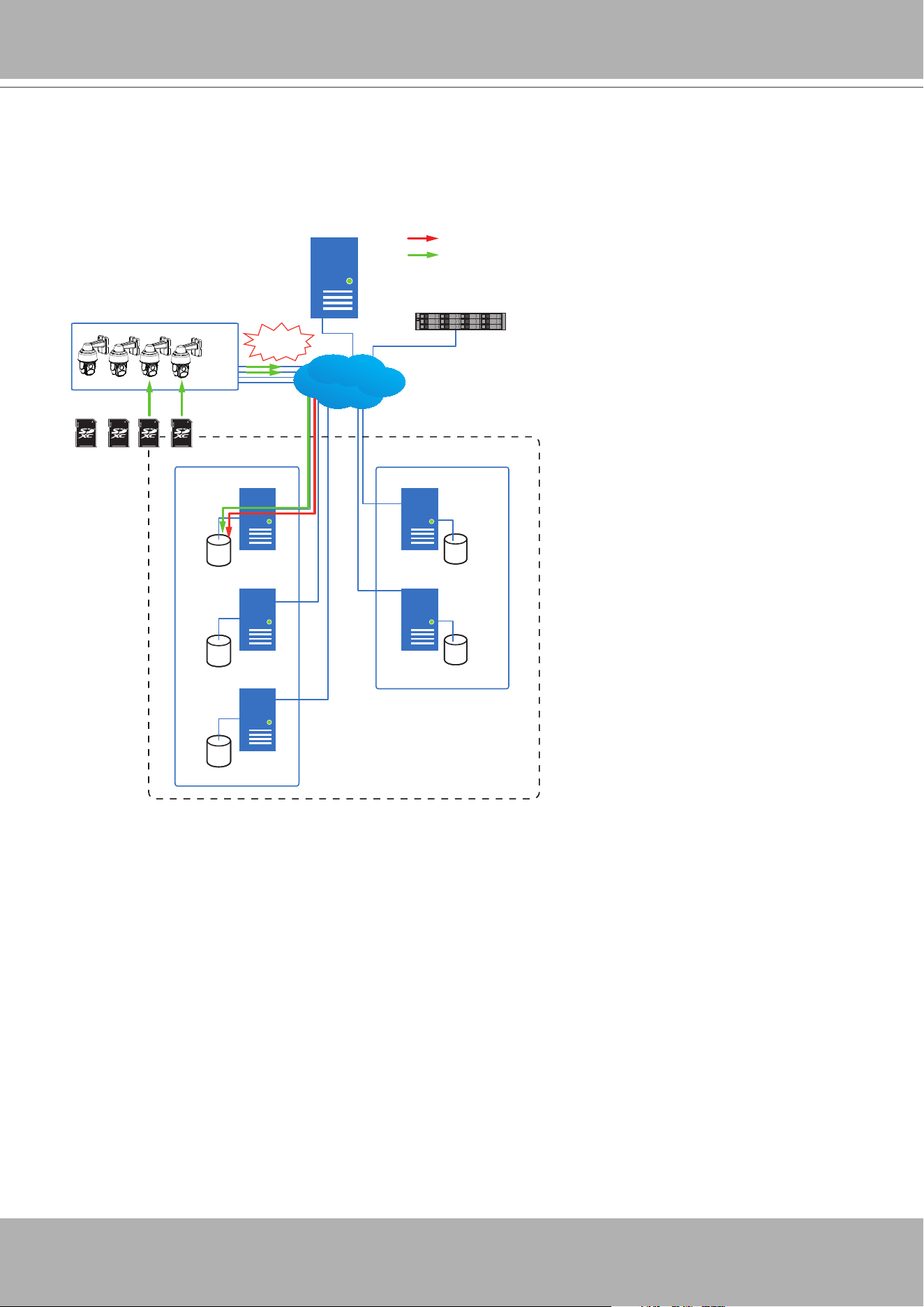
VIVOTEK - A Leading Provider of Multimedia Communication Solutions
User's Manual - 331
Once the network connection is restored, the VAST2 servers resume the recording task and also
retreive video segments from the SD cards. The video segments recorded during the network
failure will be stitched up with those occurred before and after the network failure. The retrieval
speed varies depending on the available network bandwidth and CPU resources.
Active VAST servers Redundant VAST servers
CMS VAST
Active Group Redundant Group
Node 1
Node 2
Node 1
Node 2
Node 3
External storage /
NAS
Network Cameras
. . . . .
Server Group 1
Recording
Retrieval
LAN
Recovered!
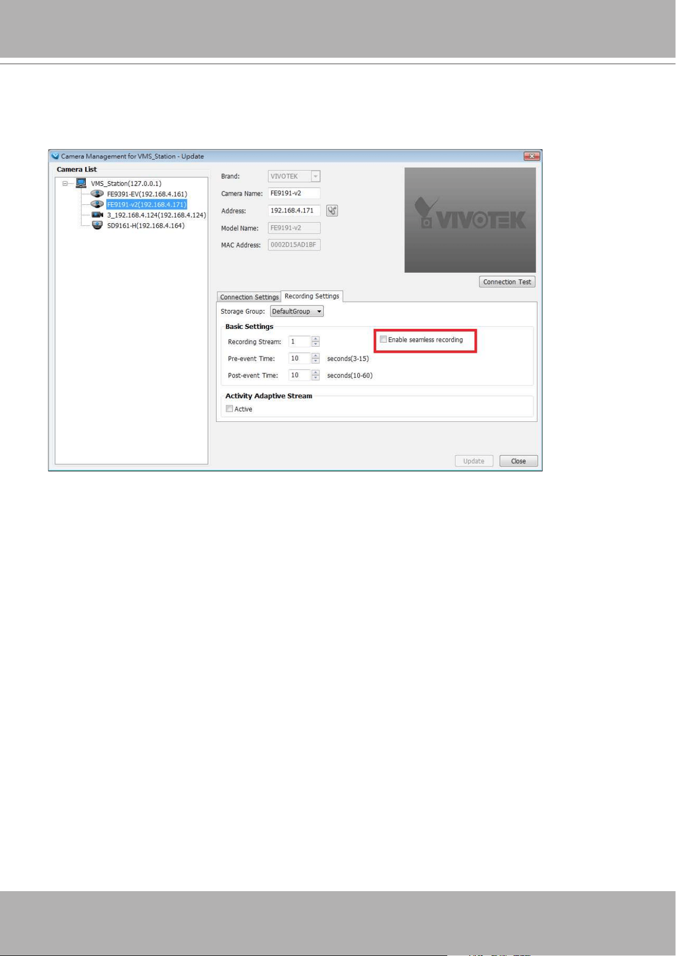
VIVOTEK - A Leading Provider of Multimedia Communication Solutions
332 - User's Manual
To enable Seamless recording, nd the associated option in
Conguration
>
Camera
Management
>
Camera Update
, and select the Seamless recording checkboxes. Camera
models that support the Seamless recording option will have it listed.
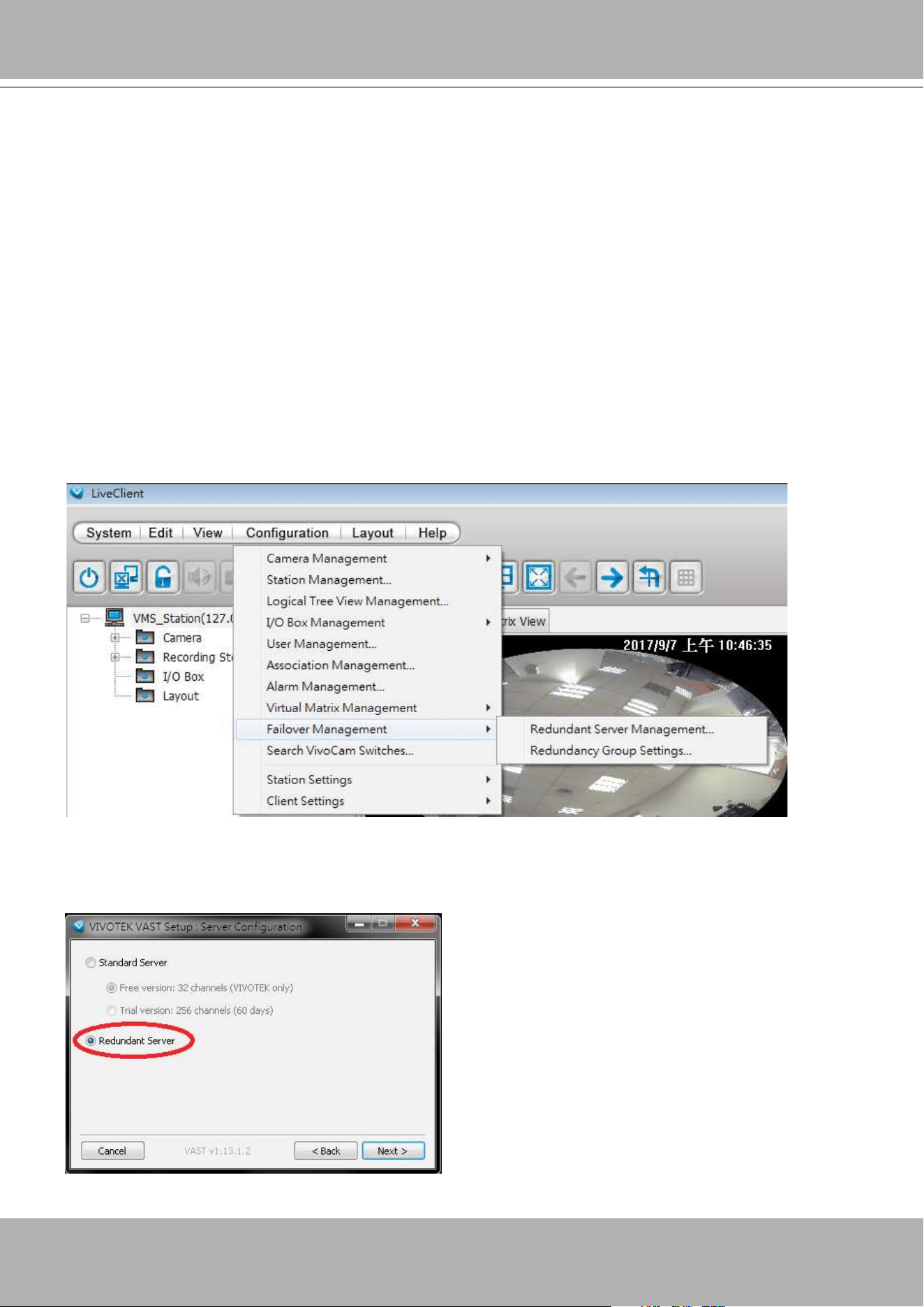
VIVOTEK - A Leading Provider of Multimedia Communication Solutions
User's Manual - 333
Before Failover conguration, you need to add other servers to your Failover conguration.
• If you are adding a Redundant server, enter the "
Redundant Server Management
" screen.
• When adding a Redundant server, you can provide a Windows account 802.1x domain user
name and password. A Redundant server requires this because a full access to the recorded
data is required during the failover and failback process.
Failover Conguration Process
Note that it is a must for the Redundant server to be installed differently by selecting a
"
Redundant server
" checkbox during the installation process.
To congure Redundant servers,
1. Install VAST server on a server chosen as the active standby.
2. On the server chosen as the VAST CMS server, open
Conguration
>
Failover
Management
>
Redundant Server Management
.
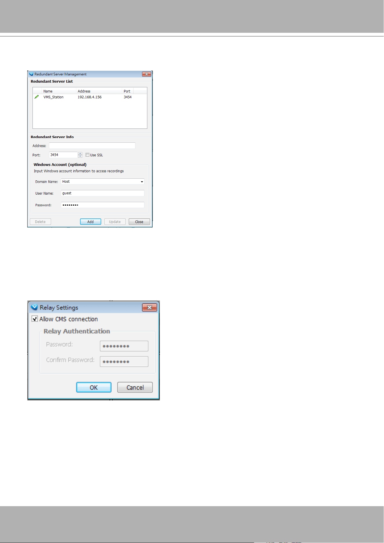
VIVOTEK - A Leading Provider of Multimedia Communication Solutions
334 - User's Manual
3. Enter the IP address and Windows AD credentials for access to the Redundant server. Click
the Add button when done, and click the Done button to leave this page.
An Active server must have a CMS password congured for the hierarchical conguration.
Note that on the Active servers, you should congure them as the subordinates to your CMS
VAST server. On a web console with these servers, open the Site management page, and select
"
Allow CMS connection
." Create a common password for the CMS hierarchy.
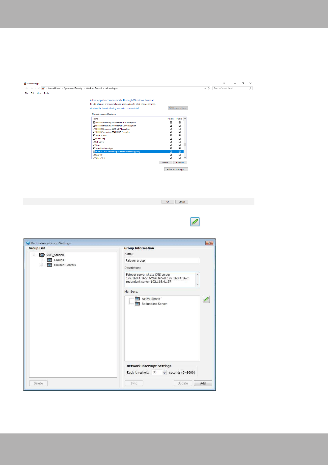
VIVOTEK - A Leading Provider of Multimedia Communication Solutions
User's Manual - 335
Two agents will be running on the Active and Redundant servers, "stunnel" and
"VMSWebServer." Make sure they are not blocked out by your rewall. These agents can be
found in the default folders below:
C:\Program Files (x86)\VIVOTEK Inc\sTunnel\stunnel.exe
C:\Program Files (x86)\VIVOTEK Inc\VAST\Server\VMSWebServer.exe
4. Enter
Conguration
>
Failover Management
>
Redundant Group Settings
. Enter the
Group name, Description, and click on the Edit button .
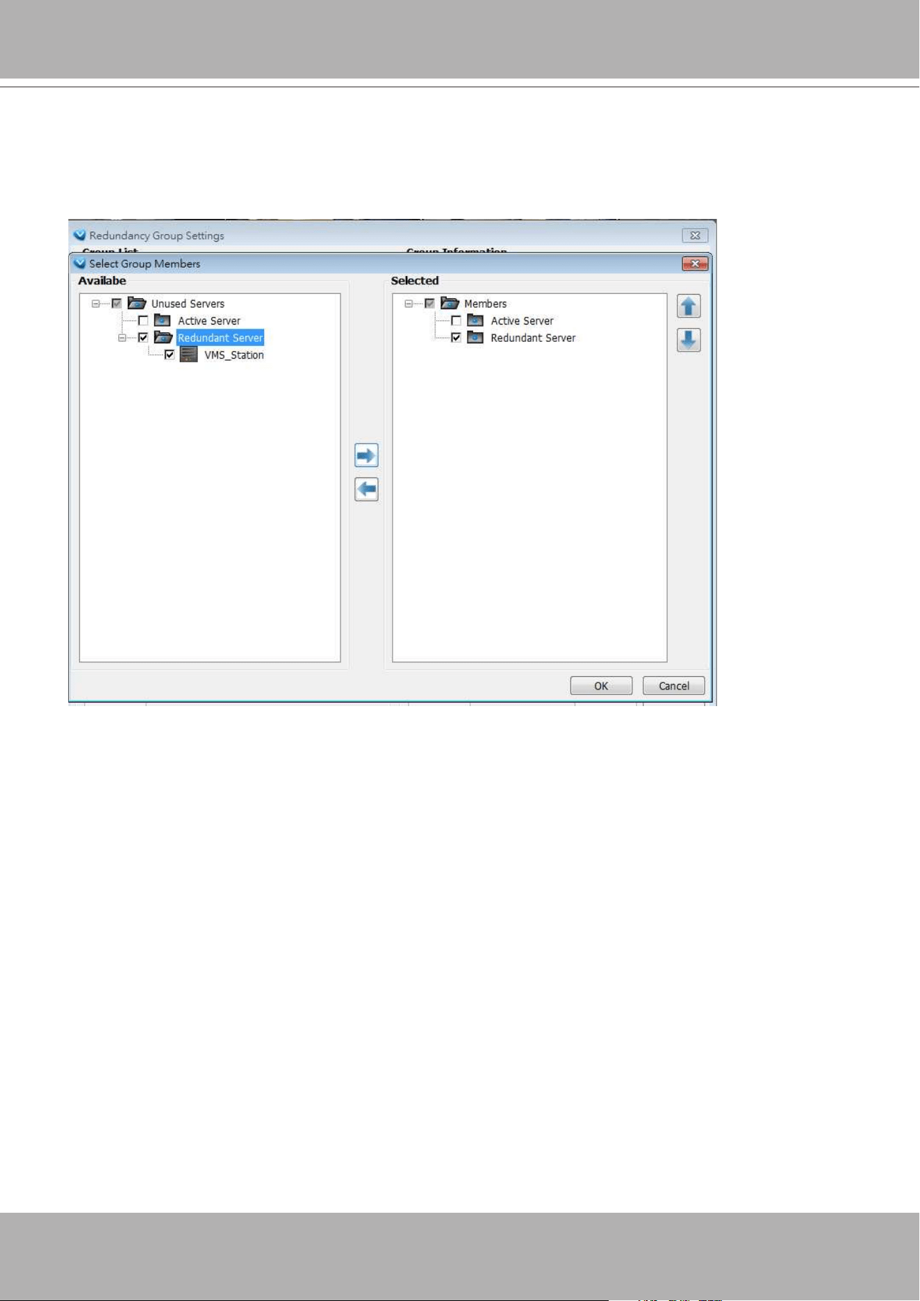
VIVOTEK - A Leading Provider of Multimedia Communication Solutions
336 - User's Manual
5. Select the Active and Redundant servers and move them to the list of Selected servers. The
Active and Redundant servers you enlisted should all be listed below. Select the members of
the Redundant group, and click OK to complete.
The default for the network disconnection timeout is 30 seconds. It is not recommended to
congure a very short timeout, e.g., 5 seconds, because if doing so, a temporary network
disorder can make servers consider the Active server(s) have failed.
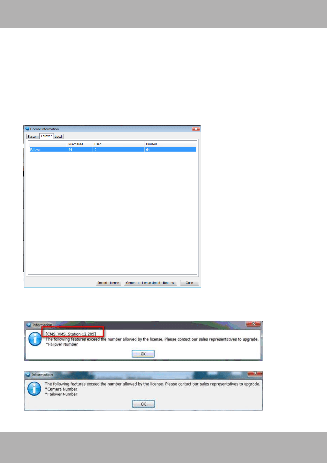
VIVOTEK - A Leading Provider of Multimedia Communication Solutions
User's Manual - 337
Using the failover function requires Failover license. On the CMS server, you can check the
number of channels in Help > Failover license. Below are the requirements for running a failover
conguration:
1. In a Redundant server group, the number of licensed channels = No. of Active server
channels x No. of Redundant server(s).
For example,
There are 3 Activer servers with 100, 125, and 165 channels.
There are 2 Redundant server.
The number of failover license channels are: 165 x 2 = 330.
2. Error prompts will display if there are not sufcient failover channels when you create a
Redundant server group.
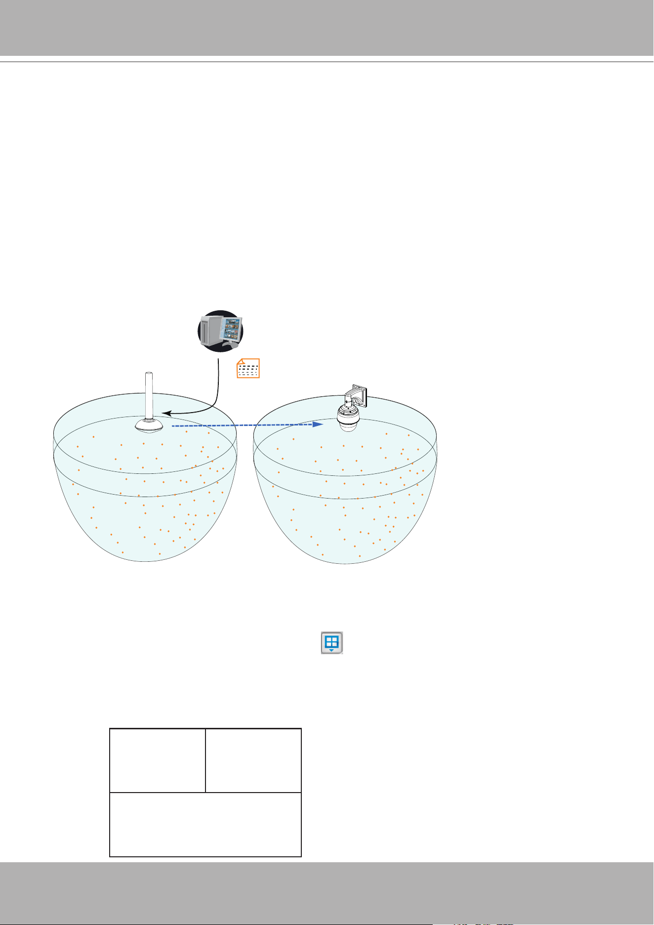
VIVOTEK - A Leading Provider of Multimedia Communication Solutions
338 - User's Manual
Appendix B Panoramic PTZ (P-PTZ) Conguration
Enable Panoramic PTZ on VAST
The process of configuring two cameras (1 fisheye and 1 speed dome) into the Panoramic
PTZ conguration takes place on a PC using the calibration tool. The Auto Tracking feature is
configured using a web console with the fisheye camera. A Panoramic PTZ package should
comprise two cameras running specific firmware for this application and a software CD
containing all necessary utilities. For conguration details, please refer to the
Panoramic PTZ
Installation Guide
.
Mapping table
360°
All round view
ref. point 1
ref. point 2
ref. point 3
ref. point 4
ref. point 5
ref. point 6
ref. point 7
ref. point 8
ref. point 9
ref. point 10
ref. point 11
ref. point 12
ref. point 1
ref. point 2
ref. point 3
ref. point 4
ref. point 5
ref. point 6
ref. point 7
ref. point 8
ref. point 9
ref. point 10
ref. point 11
ref. point 12
Calibration tool
Pan/Tilt/Zoom
control
To exert Panoramic PTZ control on VAST:
1. Once these two cameras are congured into an interactive pair, insert these cameras into
your VAST conguration.
2. Select a preferred layout using the Layout
button. The 1P+2, 1P+6, and 1P+8 layouts
are specically designed for the Panoramic PTZ conguration.
3. Taking the 1P+2 layout as an example, once they are listed on the device list, click and drag
the sheye camera to the upper left and the bottom view cells. Place the speed dome in the
upper right view cell.
Fisheye 1O Speed Dome
Fisheye 1P
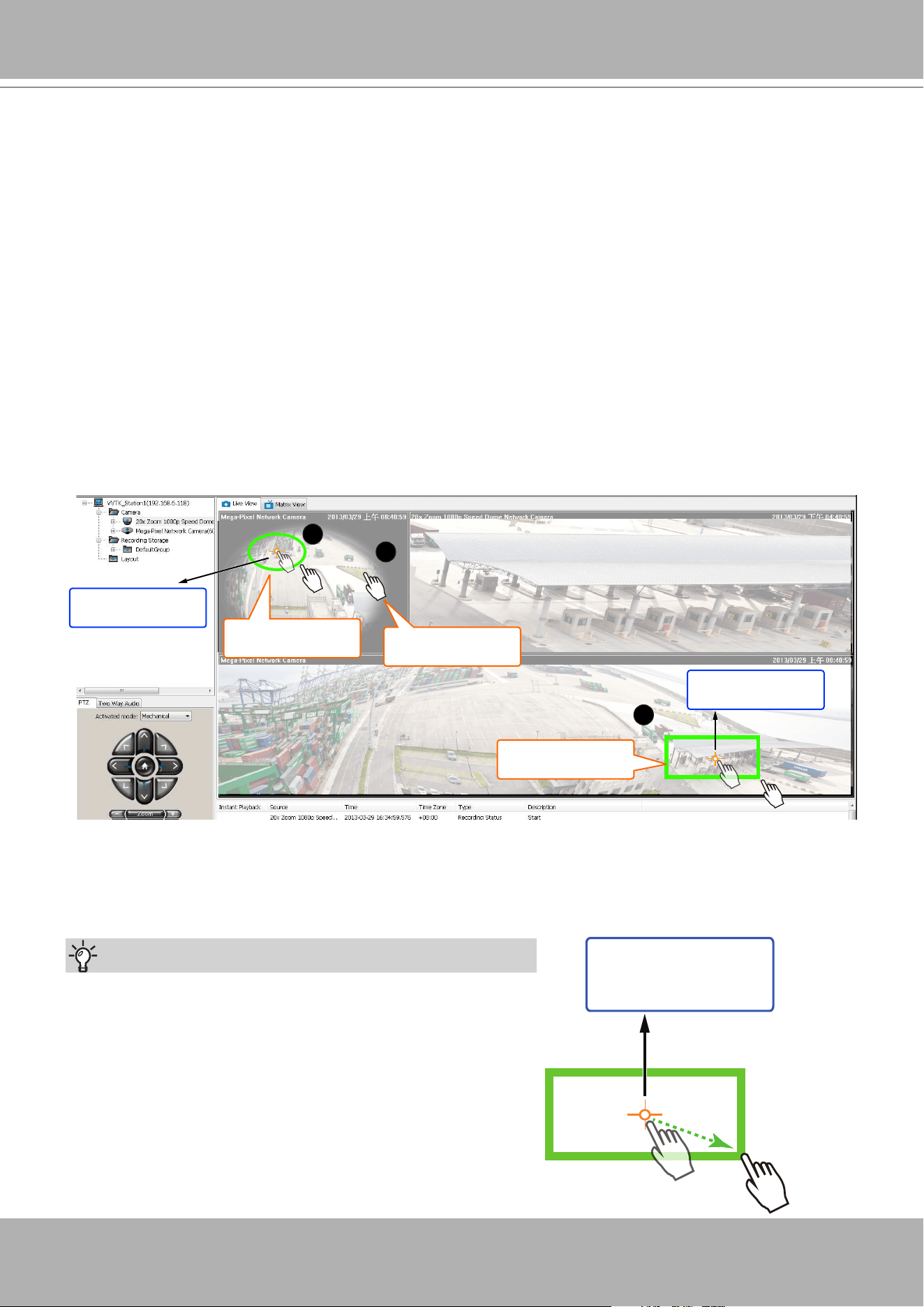
VIVOTEK - A Leading Provider of Multimedia Communication Solutions
User's Manual - 339
4. Right-click on the sheye's view cell to change its Display mode either into the
1O
(Original)
or the
1P
(Panoramic) mode. Note that the Panoramic PTZ control does not take effects on
the "
R
" (Regional) mode and the combinations of other display modes.
1
Click to move
2
Click and drag
2
Click and drag
Object
of your interest
Object
of your interest
5. There are two different ways to quickly exert Panoramic PTZ control. The pan, tilt, and zoom
actions are made from the sheye's 360
°
hemispheric overview:
5-1. Click on a spot on the sheye's Original or Panoramic view where you detected a
condition of your interest. The speed dome will aim its lens at the corresponding position
to cover that eld of view.
5-2. Click and drag a region of interest either on the Original or on the Panoramic view. The
speed dome will move to that region and zoom in to ll the same proportion of view into its
view cell.
• On the Original view, click-and-drag creates a circular region of interest.
• On the Panoramic view, a square region.
• If you draw a small region, the speed dome will zoom in on the scene. The smaller the
region, the larger the zoom-in ratio. A large region makes the speed dome to zoom out.
The speed dome camera automatically performs optical zoom in/out to best t the selected
eld of view until the maximum and minimum zoom ratio is reached.
Tips:
1. When drawing a region of interest, click and drag from
the center of your interest over a diagonal line to the
bottom right. It is not like drawing a diagonal line from
corner to corner.
2. To swipe the Panoramic view left or right, press and
hold down the
Ctrl.
key and the left mouse button.
Object
of your interest
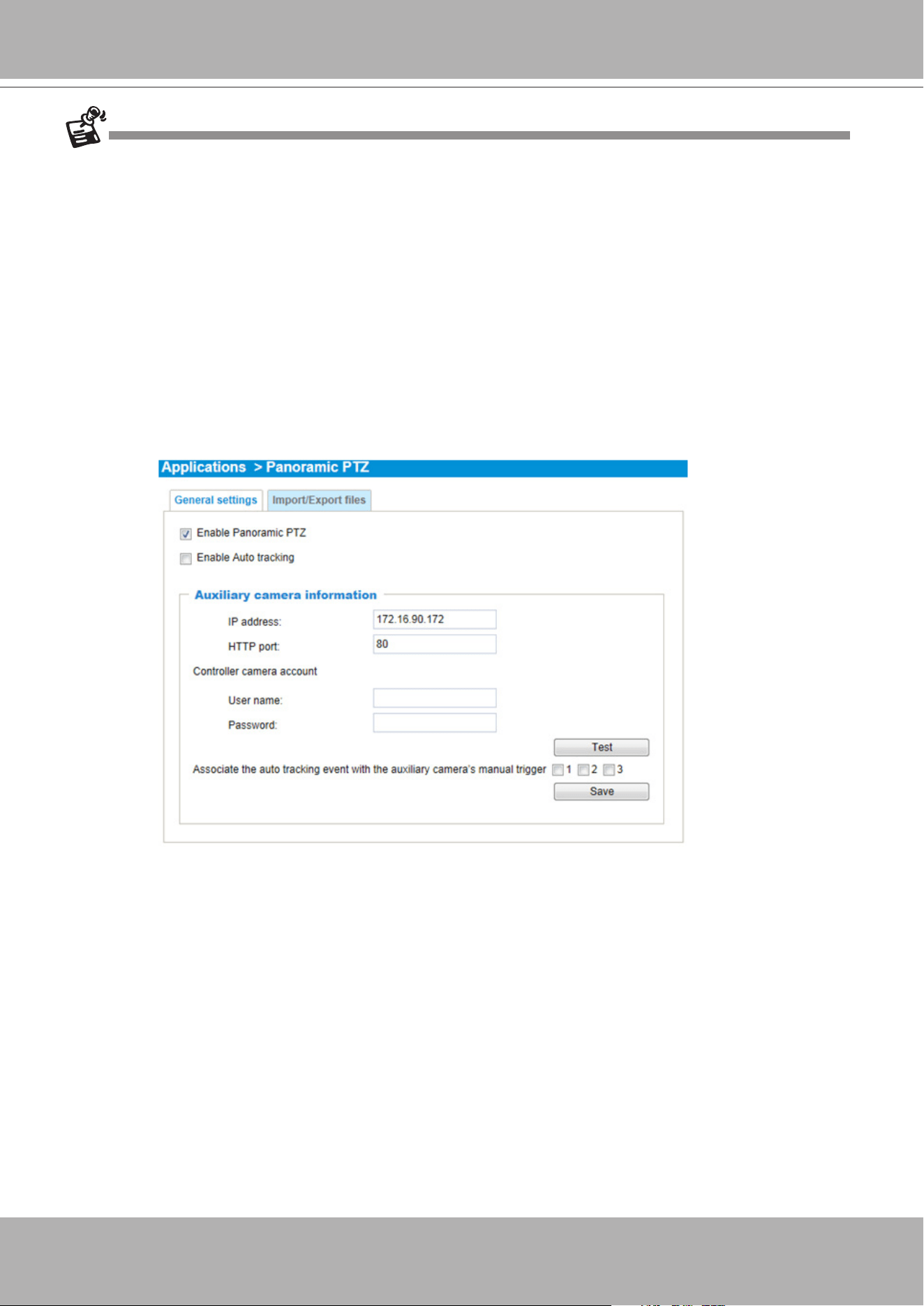
VIVOTEK - A Leading Provider of Multimedia Communication Solutions
340 - User's Manual
1. The sheye and the speed dome are made into an interactive pair using the calibration tool. The VAST
software provides the control interface only. If the cameras have not been properly congured, the
Panoramic PTZ function will not take effect.
2. If the password of the speed dome camera has been changed, you will need to open a web console
with the sheye camera to change the coordinate password.
3. You may need to reset the sheye camera if the speed dome camera is powered on after you started
the VAST software.
4. The precision level of the interactive positions between the view cells of the sheye and the speed
dome is determined by the mapping table. Make sure you have inserted a sufcient number of
reference points and make good association of these points using the calibration tool.
5. Currently the associated event trigger by Auto Tracking is not supported on VAST. The associated
event triggering is congured through a web console with the sheye camera:
5-1. You should then create an event setting using the manual triggers as triggering sources.
5-2. When Auto Tracking takes place, the pre-congured event settings on the speed dome camera
can take associated actions, e.g., taking a snapshot, recording to SD, or triggering the DO pins.
6. The Panoramic PTZ function is currently not available on the Matrix or web console mode in VAST.
7. If the interactive camera pairs (Panoramic PTZ cameras) are managed under VAST substations, then
all of the VAST instances, such as the primary VAST server, the substations, and the client side must
be running the revision that supports P-PTZ.
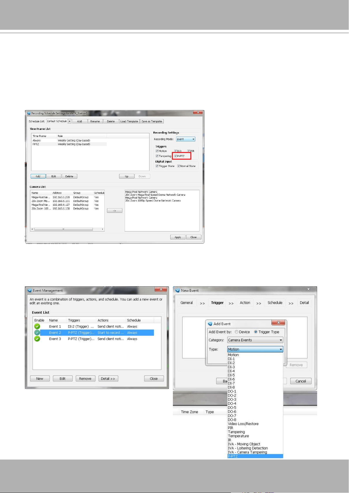
VIVOTEK - A Leading Provider of Multimedia Communication Solutions
User's Manual - 341
Panoramic PTZ - Event Trigger
The P-PTZ-related event types include: "triggered" and "returned to normal" when Auto Tracking
takes place. Below are the congurable options with the event conguration:
1. When conguring a recording schedule, the Auto Tracking actions can be selected as one of the event
triggers. The conguration is found in
Conguration
>
Station Settings
>
Recording Schedule
Settings
.
2. When Auto Tracking is enabled, its actions are considered as one of the system event types.
In
Conguration
>
Event Management
, P-PTZ is congurable as a Trigger Type in
Event
Management
>
New Event
>
Trigger
. This event trigger can be associated with different actions,
such as Email, recording, moving to a preset location, GSM message, HTTP, Client notication, etc.
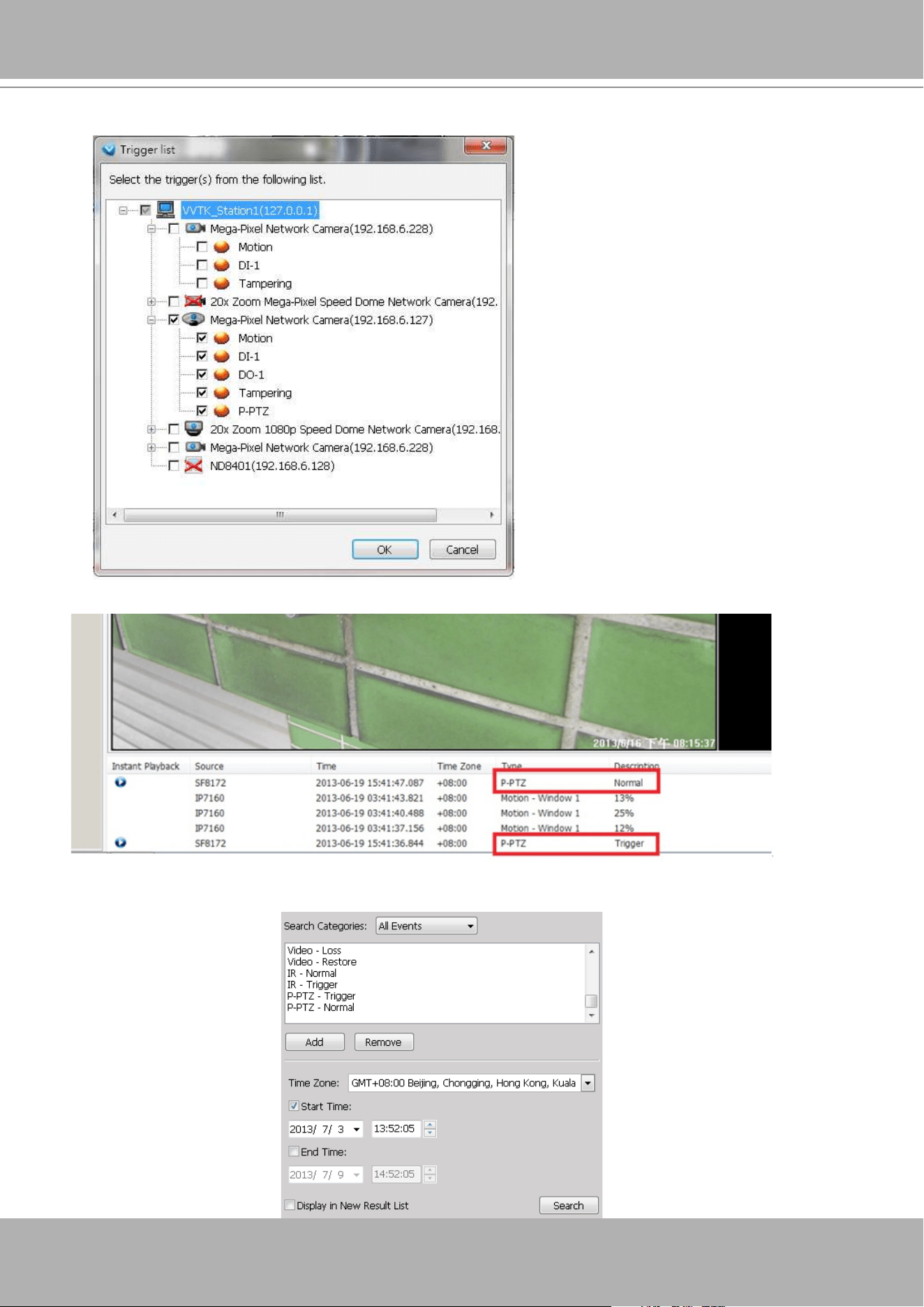
VIVOTEK - A Leading Provider of Multimedia Communication Solutions
342 - User's Manual
3. Events triggered by Auto Tracking are also recorded into system logs.
Auto Tracking can also function as a Device type in the Event Management conguration.
4. As the result, in
Playback
>
Event Search
panel, Auto Tracking (P-PTZ Trigger/Normal) is also a
search condition.
Once triggered, the P-PTZ Trigger and
P-PTZ Normal events will create two
short videos for a length of 30 seconds.
Note that the P-PTZ event is not
triggered by Panoramic PTZ control on
the view cells, it is triggered by Auto
Tracking. Auto Tracking takes place
when a moving object enters the pre-
congured region of interest. Please
refer to the
Panoramic PTZ Installation
Guide
.
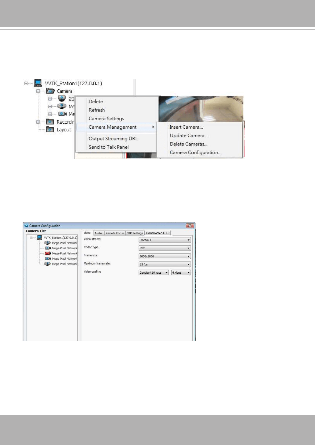
VIVOTEK - A Leading Provider of Multimedia Communication Solutions
User's Manual - 343
Enable or Disable the Panoramic PTZ Functions
You can manually enable or disable the Panoramic PTZ function in
Conguration
>
Camera
Management
>
Camera Conguration
:
1. Select the sheye camera by a single click, and then open the panoramic PTZ panel from the tabbed
menu.
2. You can enable or disable the panoramic PTZ or the Auto Tracking functionality using the checkboxes.
3. Click the Save button, and the saving progress window will prompt.
4. Click Close to end the conguration process.
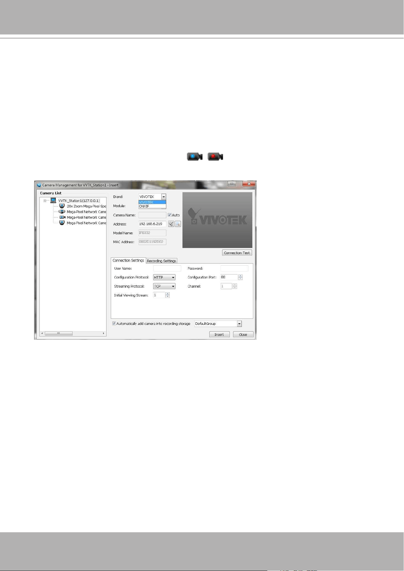
VIVOTEK - A Leading Provider of Multimedia Communication Solutions
344 - User's Manual
Appendix C ONVIF Support
ONVIF is supported in an environment where the VAST server can detect and record video
streams from the cameras made by other manufacturers.
The following are supported.
1. ONVIF camera icons on the device tree.
Brand name selection is also available on the conguration window.
2. Insert/update/delete camera from the device tree.
2-1. Detect ONVIF cameras.
2-2. Connection test.
2-3. camera password authentication.
2-4. Supports HTTP and HTTPS streaming protocol.
2-5. Supports multiple streaming.
3. Live view/recording/playback.
3-1. Audio G.711 support.
4. Mechanical PTZ support with the exception of Focus, Iris, Pan, Patrol, and preset location
operation.

VIVOTEK - A Leading Provider of Multimedia Communication Solutions
User's Manual - 345
Limitations:
The following limitations apply to ONVIF cameras made by other manufacturers. Some features
may be implemented in later releases of software.
1. Users should ensure that your other brand cameras support ONVIF.
2. The connection statuses of the other brand cameras will not be displayed on the device tree.
3. For mechanical PTZ cameras, the Focus, Iris, Pan, Patrol, and preset locations functions will
not be supported. The associated buttons and control elements on the UI screen will not be
disabled.
4. Does not support the Batch Insert Camera function.
5. Does not support Camera Conguration.
6. Does not support Active Adaptive Stream (AAS) function.
7. Does not support Event related functions, including event recording, event management,
instant playback, event search, etc.
8. Does not support camera DI/DO.
9. Does not support Two Way Audio.
10. Does not support Auto Stream Size.
11. The ONVIF user authentication (account and password) may not comply with those
congured via a web console.
12. The number of multiple proles can vary.
13. The number of accessible profile can vary. Some might have only one profile to be
connected.
14. Does not support Click on Image.
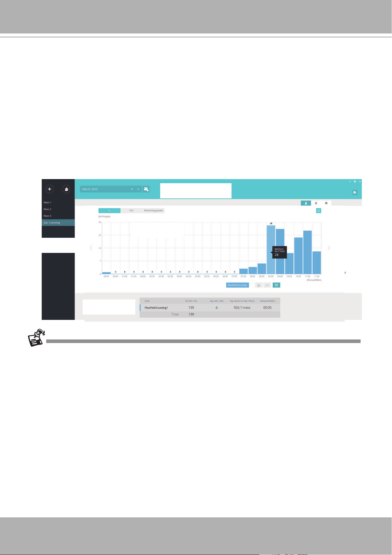
VIVOTEK - A Leading Provider of Multimedia Communication Solutions
346 - User's Manual
Appendix D VCA Report
The VCA Report utility is started from
System
menu >
Launch VCA Report
. The VCA Report
utility provides comprehensive graphs and line charts for quick access to the data collected
through VIVOTEK's People Counting modules, such as the SC8131 stereo camera. Statistical
results is refreshed by hour or minutes, and you can compare the results acquired through
different time periods or among different surveillance areas. These data help figuring the
customer ow in retails so that shop owners can optimize the arrangement of store layout, or
mange queues more efciently.
Add, Select, Edit
Areas
Time selector and function
panel
Chart panel
Area data
The conguration of detection methods in People Counting still occur on a web console with individual
cameras. It is not congurable through the VAST LiveClient.
Prerequisites:
The prerequisites for using the VCA Report are:
1.
Cameras running the VCA utilities have been configured and added into the VAST
deployment. The instances of available VCA rules will be listed in the
Area
panel.
2.
The life expectancy of VCA records is 5 years.
3.
Currently the utility supports Windows XP, 7, and 8.
4.
The latest revision v.1.12 supports Seamless Recording, in order to retrieve collected data
and recording during Ethernet disconnection. Provided that an SD card is installed on
the SC8131 camera, the VAST station gradually retrieves data from the SD card after the
connection is restored.
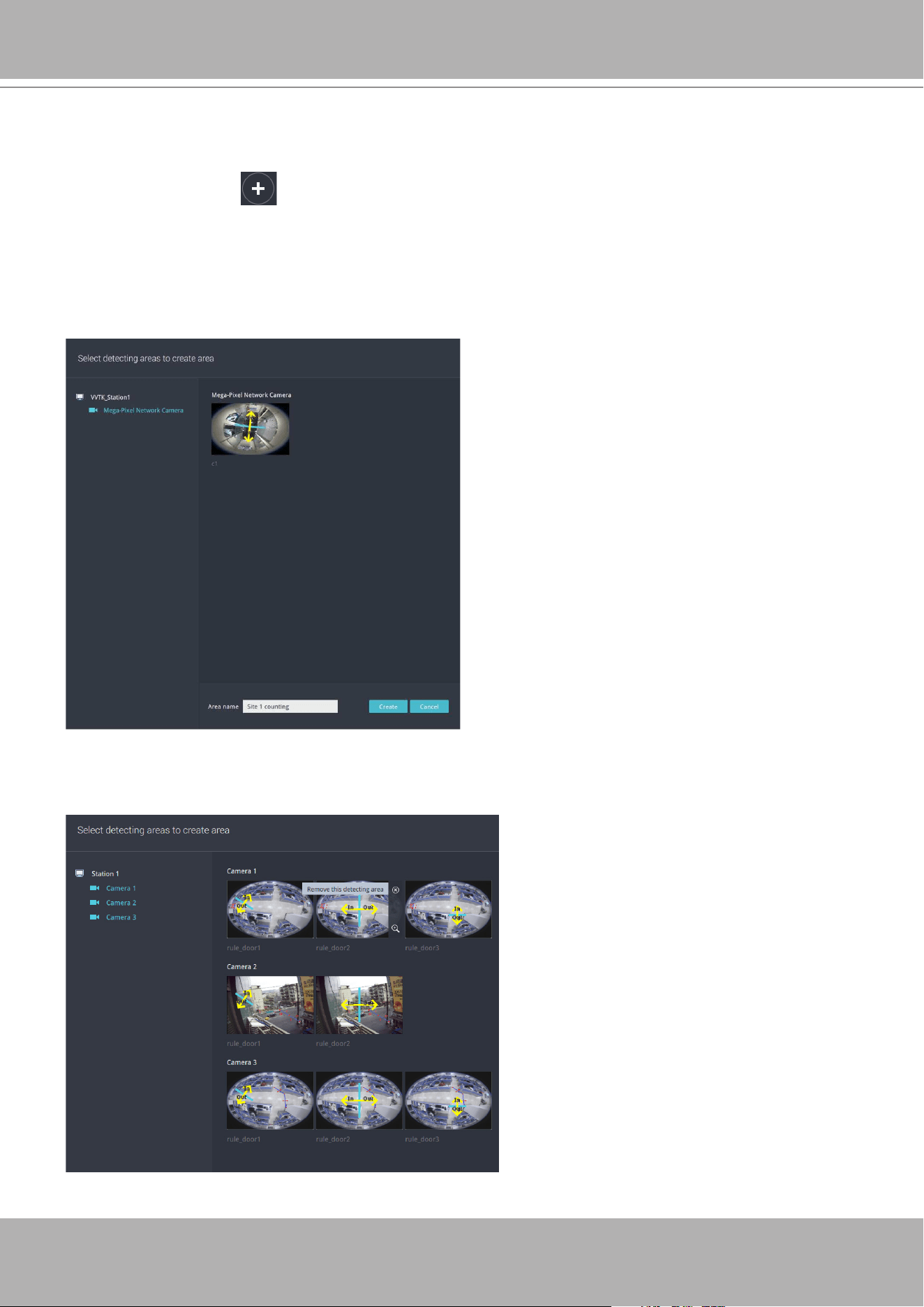
VIVOTEK - A Leading Provider of Multimedia Communication Solutions
User's Manual - 347
To begin using the VCA report:
Create Areas
1. Click on the
Add
button in the
Area
panel. Cameras running the VCA utilities will be
listed. Click to select cameras. Those running multiple detection rules will be displayed on
screen. Data collected for these rules is kept in camera's ash memory.
2. Click to select one or more cameras.
3. Enter a name for the area, and then click the
Create
button.
4. The Areas thus added will be listed on the Area panel on the left side of the screen.
If you have multiple detection rules on cameras, you can manually remove some of them from
the list by mouse-overing the rules. After you congured an area, you can still right-click on an
area to congure its parameters.
If only one camera is selected, its name
will apply as the Area name. If not, enter
a name for the area.
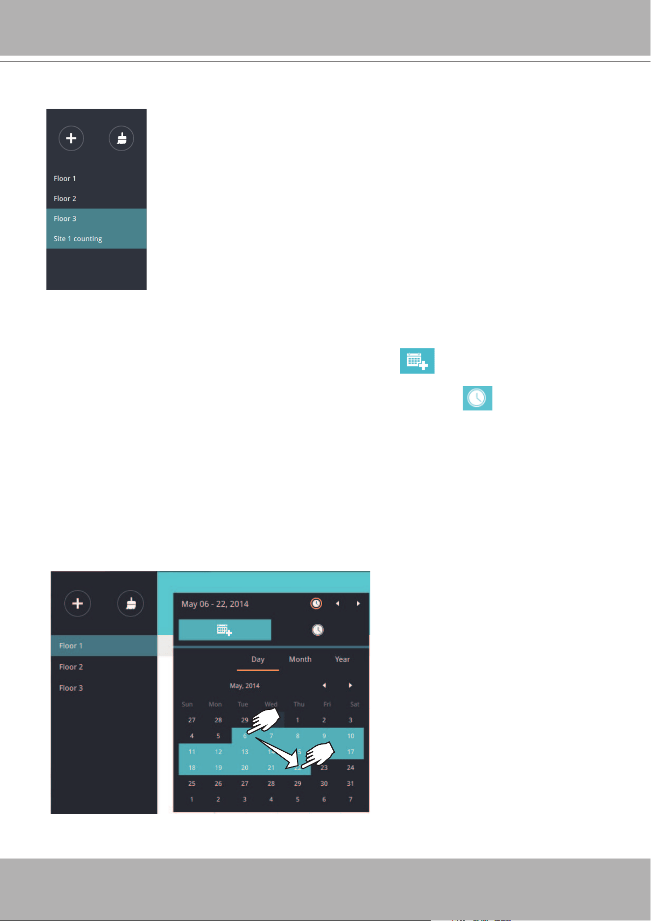
VIVOTEK - A Leading Provider of Multimedia Communication Solutions
348 - User's Manual
Select Date & Time
6. By default, the time displayed on the calendar is the current system time on the client
computer running the utility. Select from the
Date
selector
on top.
7. Select a date or span of time from the calendar or use the and
Time
selector to select a
span of time.
> Single-click to select a date or click and drag to select multiple dates.
> You can select a month or a year using a single click. If you select a month, the timeline unit
will be days within the month. If you select a year, the timeline units will be the months in a
year.
> In the
Month
or
Year
panel, single click to select the entire month or an entire year. Double-
click to select sub-units, e.g., days within a month. If you double-click on a Month panel, you
will enter the Day panel.
5. Click to select one or multiple areas. Those selected will be highlighted in a different color.
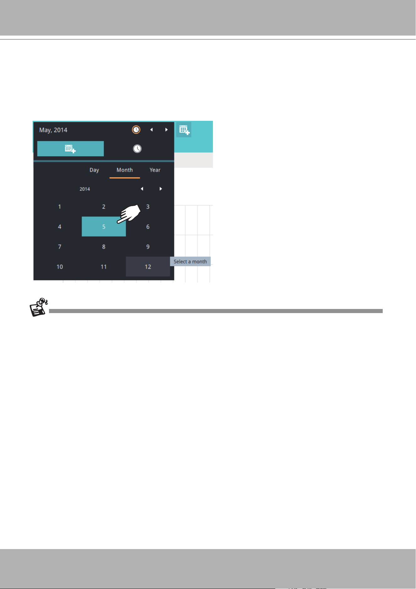
VIVOTEK - A Leading Provider of Multimedia Communication Solutions
User's Manual - 349
x2
You can select a different month in the
Month
or
Year
panels. The
Calendar
panel
disappears if left unattended for 2 seconds.
On a
Month
panel, double-click to select a month, and the
Day
panel for that particular
month will display.
• When a date is selected, the Date and Time panel will not automatically close, and the
conguration changes will not take effect until it is closed. You can click on the outside of the
panel to leave the panel.
• You can select multiple days to form a span of time. Select one date with a single click and
select multiple dates by draging your cursor across the screen to a preferred end date.
• To select a year, click to open the
Year
panel. Single click to select a year. Multiple years can
be selected using the click and drag method.
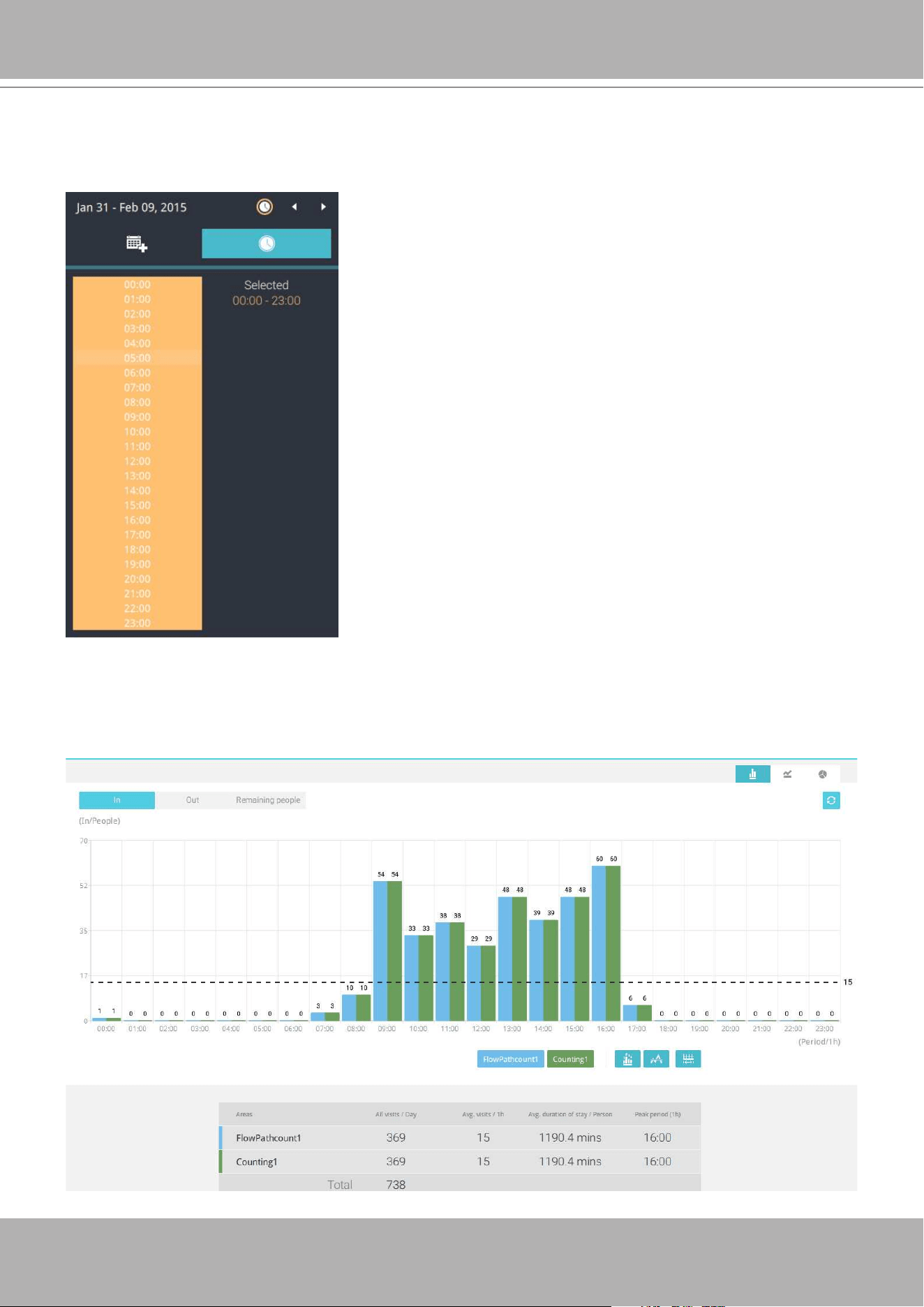
VIVOTEK - A Leading Provider of Multimedia Communication Solutions
350 - User's Manual
8. Select the hours to be included in the statistical poll using multiple clicks on the chart.
Single-click to select an hour or click and drag to select multiple hours.
9. Click outside the Calendar panel. The statistical results will display. The default display is the
bar chart. Below is a sample screen showing the results polled from 3 areas. Up to 8 areas
can be selected in one view.
Note that you can only compare the counting results
from two spans of time if you select only one Area. If you
selected multiple Areas, you can not compare the results
from multiple time spans.
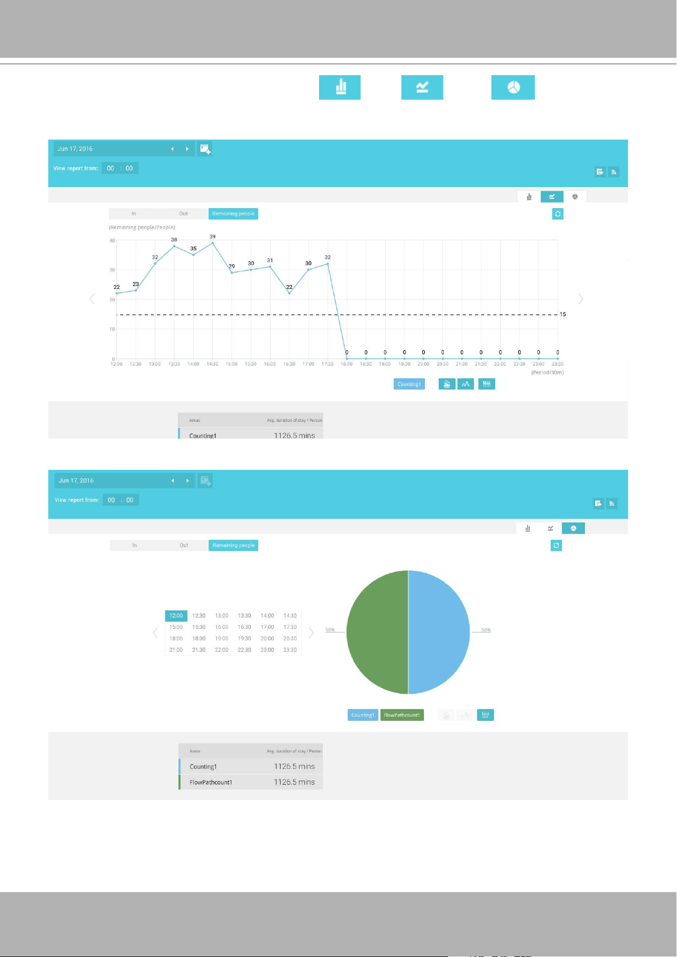
VIVOTEK - A Leading Provider of Multimedia Communication Solutions
User's Manual - 351
Select different display modes using the
Bar
,
Line
, or
Pie
chart buttons.
Line chart.
Pie chart.
Note that the timeline units can vary depending on the span of time you selected on the
Calendar panel. If a date was selected, hourly data will display in chart. If a year was selected,
monthly data will display in chart.
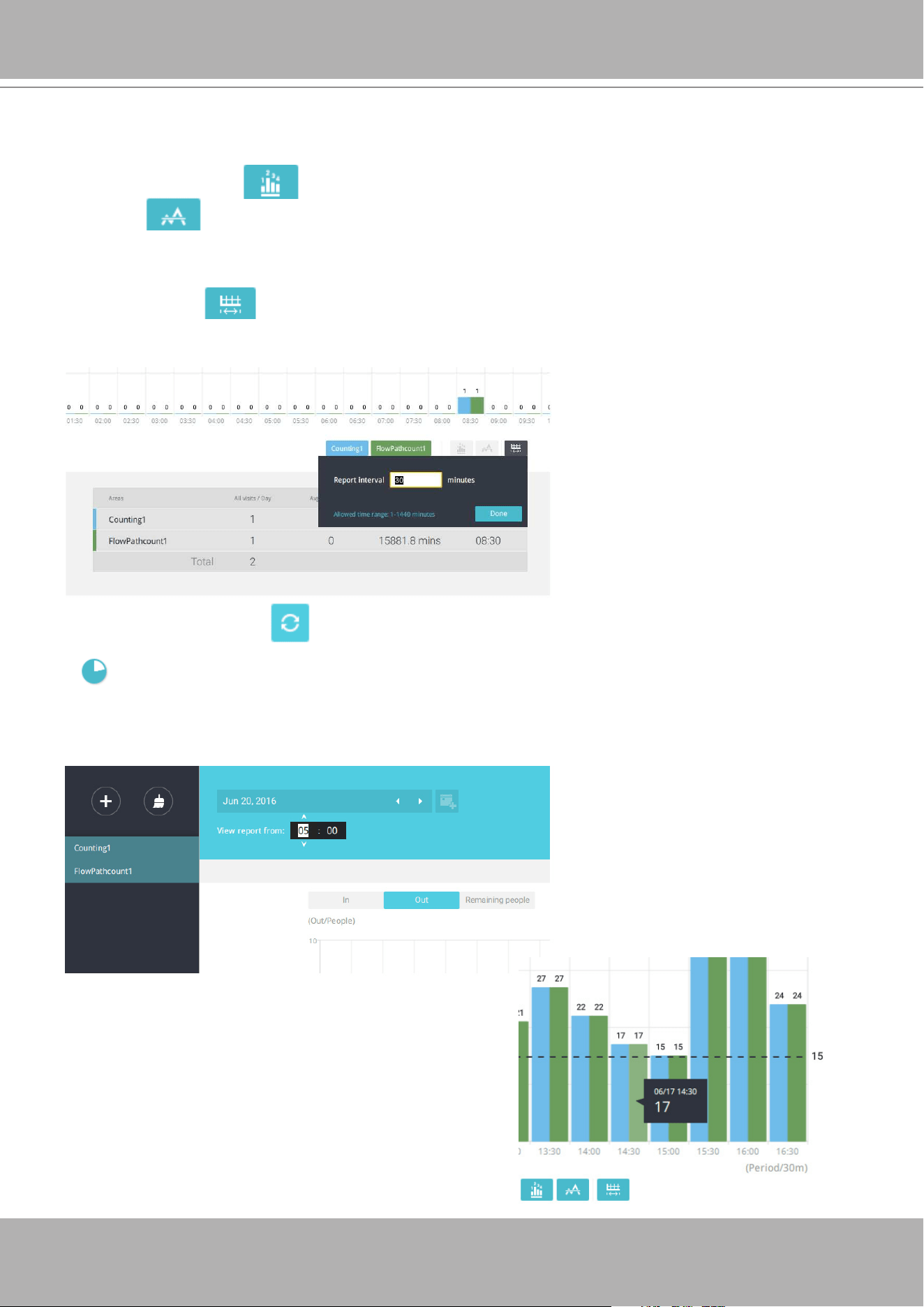
VIVOTEK - A Leading Provider of Multimedia Communication Solutions
352 - User's Manual
Use the following functional buttons to change the display parameters
Show data on chart
: Displays the collected numbers on chart.
Average
: Displays the average number per time span unit (e.g., per hour). If the interval
is changed to 30 mins, the average number will be halved comparing to the number acquired
by every hour.
Report Interval
: Congure the intervals for polling data from the camera. The default for
displaying results is by every hour. If you enter 30 minutes as the display interval, all data will
be listed on the basis of the 30 minutes time span. The congurable range is 1 to 1440 mins.
Use the
Refresh
button to poll the latest data from camera.
Use the time selector on the
View Report from
pane to select the start time of your statistics
view window. Data collected before that time will not be displayed.
A number is displayed when you mouse over an
area on the chart. Move your cursor to an area on
chart, and the number is displayed.
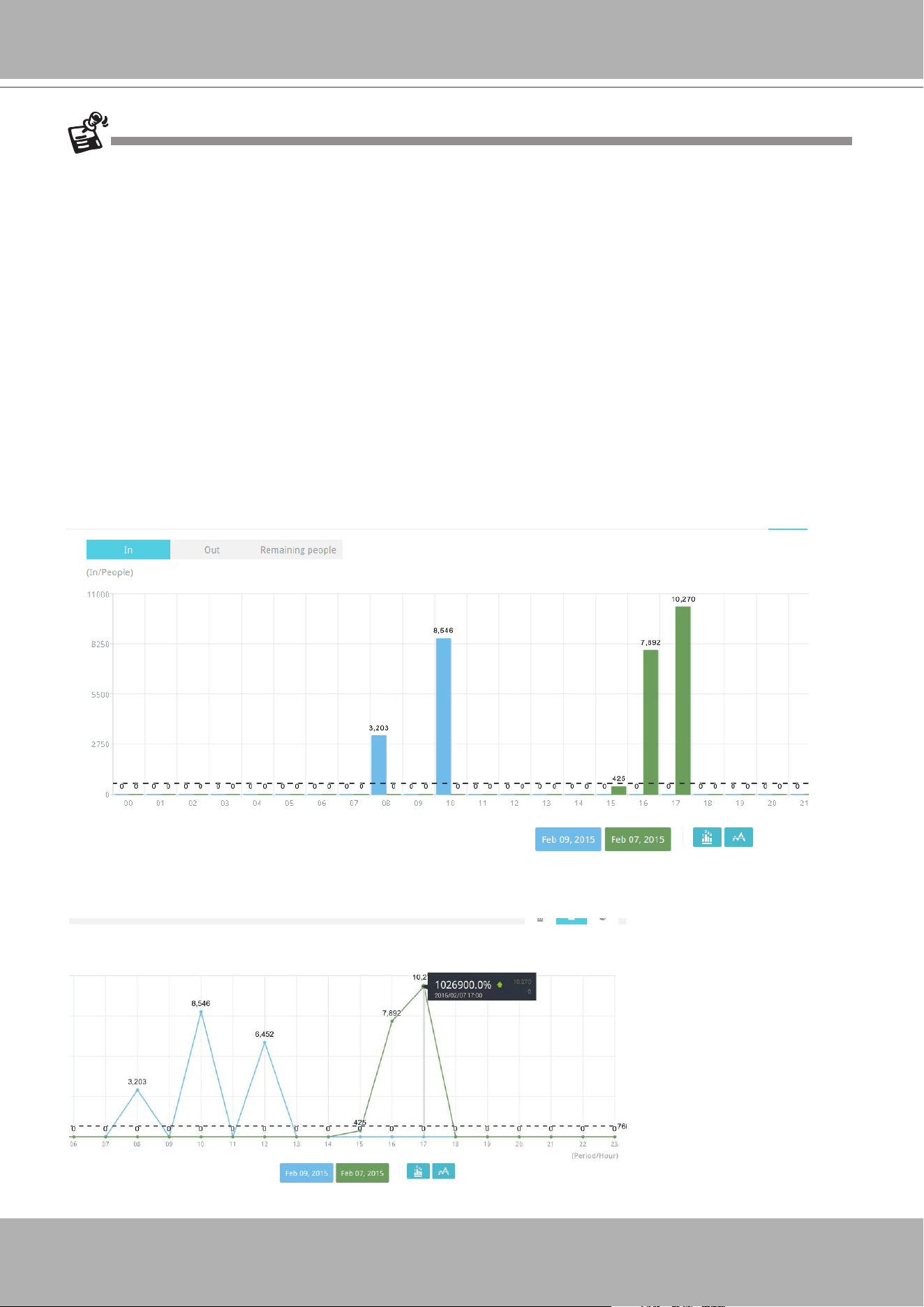
VIVOTEK - A Leading Provider of Multimedia Communication Solutions
User's Manual - 353
If you selected only one area, you can use the Shift key to select multiple areas (or two spans of
time). You can select multiple dates in the Calendar panel.
Data on a time line will be generated. To close the window, use the close button on the second
date information. Equivalent spans of time can also be used for comparison. For example, you
can compare the data in a span of 4 days against another span of 4 days.
Note that the Compare function only applies when you select to display only one area on
screen.
In a comparison result displayed in a line chart, mouse over to the peak value to display the
percentage of an increase or decrease rate.
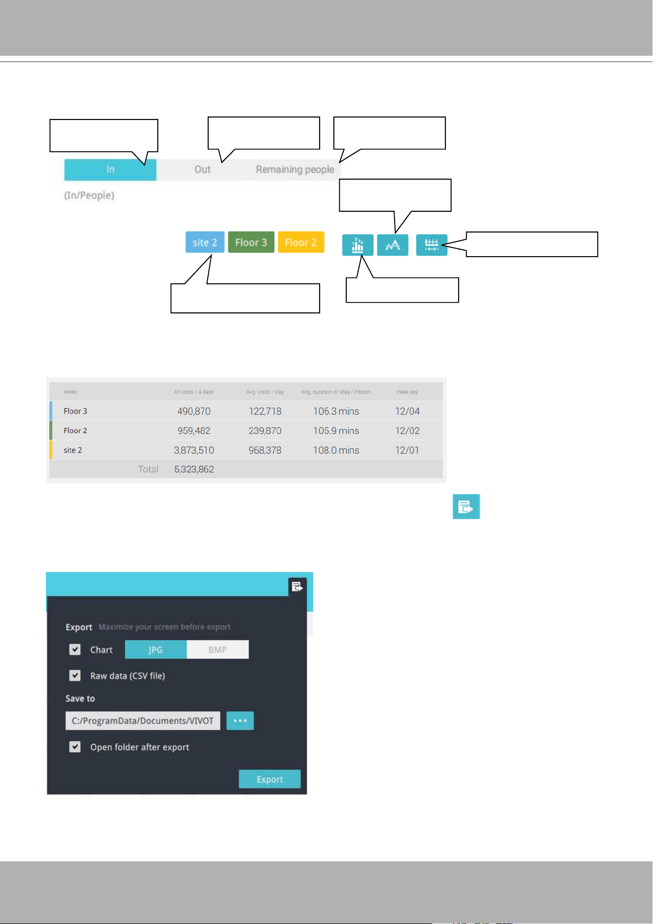
VIVOTEK - A Leading Provider of Multimedia Communication Solutions
354 - User's Manual
See below for the functions of buttons on screen.
Click to display or
hide the results for an area
No. of people who
entered the area
No. of people who
left the area
No. of people who
remain in the area
Show an average
number
Show data on chart
Change the time interval
In addition to the charts, a summary of displayed data will be listed below showing the areas
involved, visits/Day or Month, Average visits / Hours / Days, Average duration of stay / person,
and the Peak hour.
10. When done with displaying the results, you can use the
Export
button to produce an
image file to preserve the current results. Both a spreadsheet and a graphic chart will be
produced.
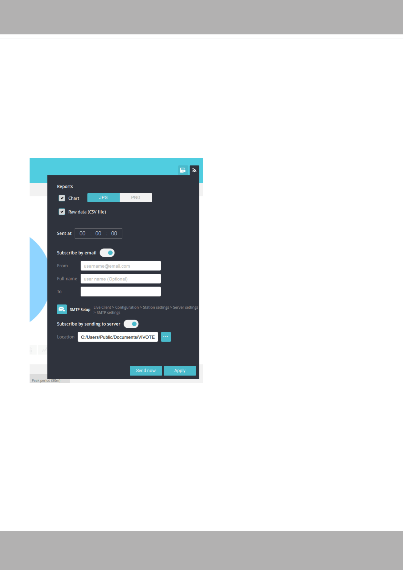
VIVOTEK - A Leading Provider of Multimedia Communication Solutions
User's Manual - 355
11. Click the Reports Subscription button to configure the regular report sent to your Email
account or a specic location on the server itself. Select the report chart image in JPEG or
PNG, and CSV data les. Slide the email button to enable the Email notication.
Select the time to deliver your mail notication. Enter valid Email addresses as the sender
and receiver addresses and make sure the SMTP mail server configuration has been
properly congured on your VAST server. This VCA mail notication utilizes the mail service
on VAST for regular notication. You can then receive Email notication every day on your
Email account. You can enter up to 5 recipient addresses.
Note that the notification contents is your current field of view, including a Bar, Line, and
Pie chart combined into one image le. The In/Out/Remaining results will be generated into
3 charts. Each Area will generate one CSV le, and each CSV data le will contain In/Out/
Remaining/Summary information.
The generated file names will look like this: 20160226_test02_Remain.jpg for charts and
20160226_Summary.csv for CSV files. The Email subject will be "VCA Daily Report -
2016/02/26."
Note that if you manually export a report, the default is sending the data collected until one
hour before the manual export. For example, if you generate the report at 14:07, the report
will only cover the data collected until 13:59. You may use the Refresh button to manually
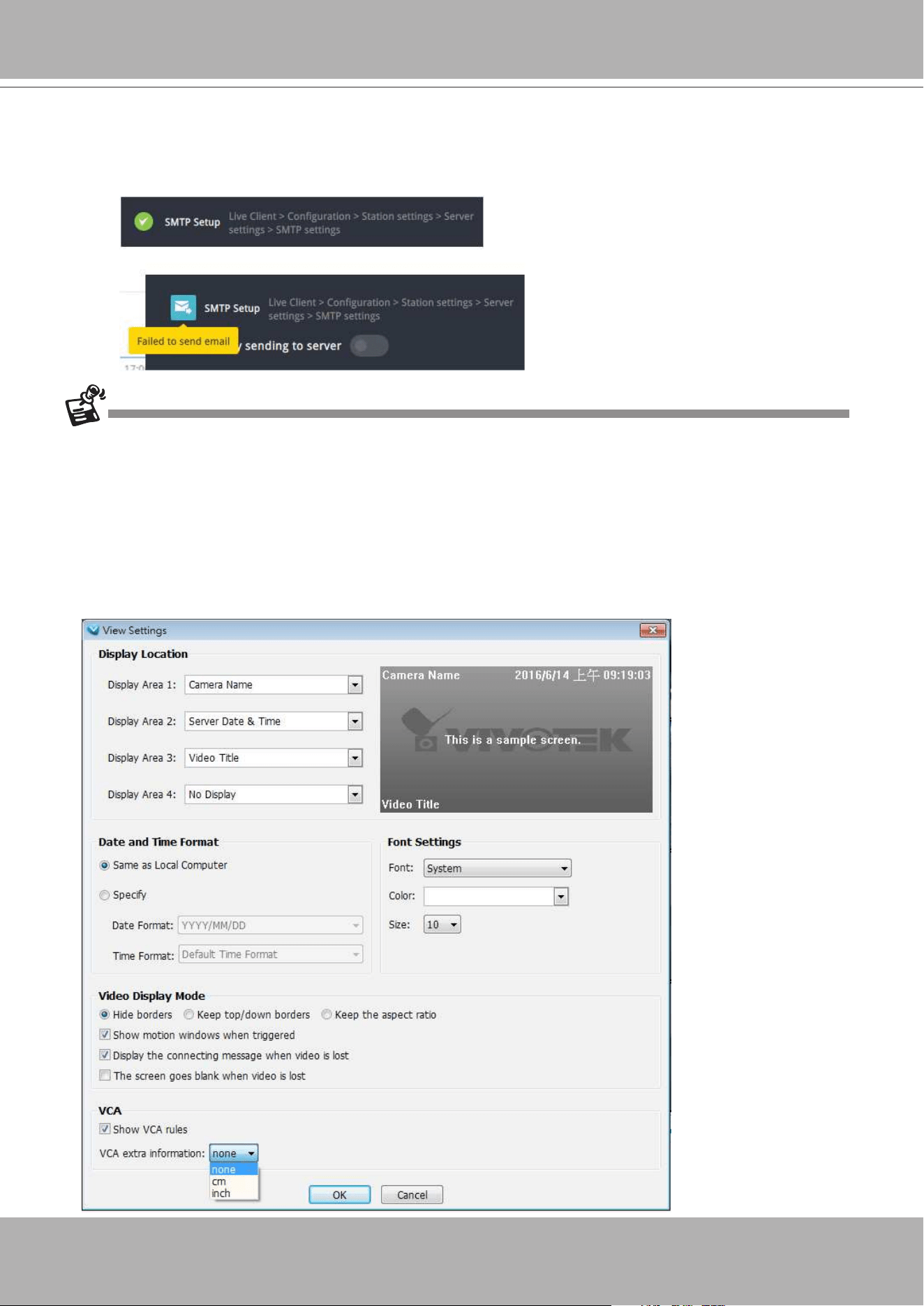
VIVOTEK - A Leading Provider of Multimedia Communication Solutions
356 - User's Manual
• If changes have been made to the VCA People Counting configuration through a web
console, Refresh the connection with a network camera from the Device Tree. You can left-
click to select a camera and right-click to display the
Refresh
command.
• The object height information detected by cameras is displayed on screen. You can select to
display such information in centimeters or inches in
Conguration
>
Client Settings
>
View
Settings
.
immediate data inputs (those occurred between 14:00 and 14:07).
Below are the messages with the Email test function.
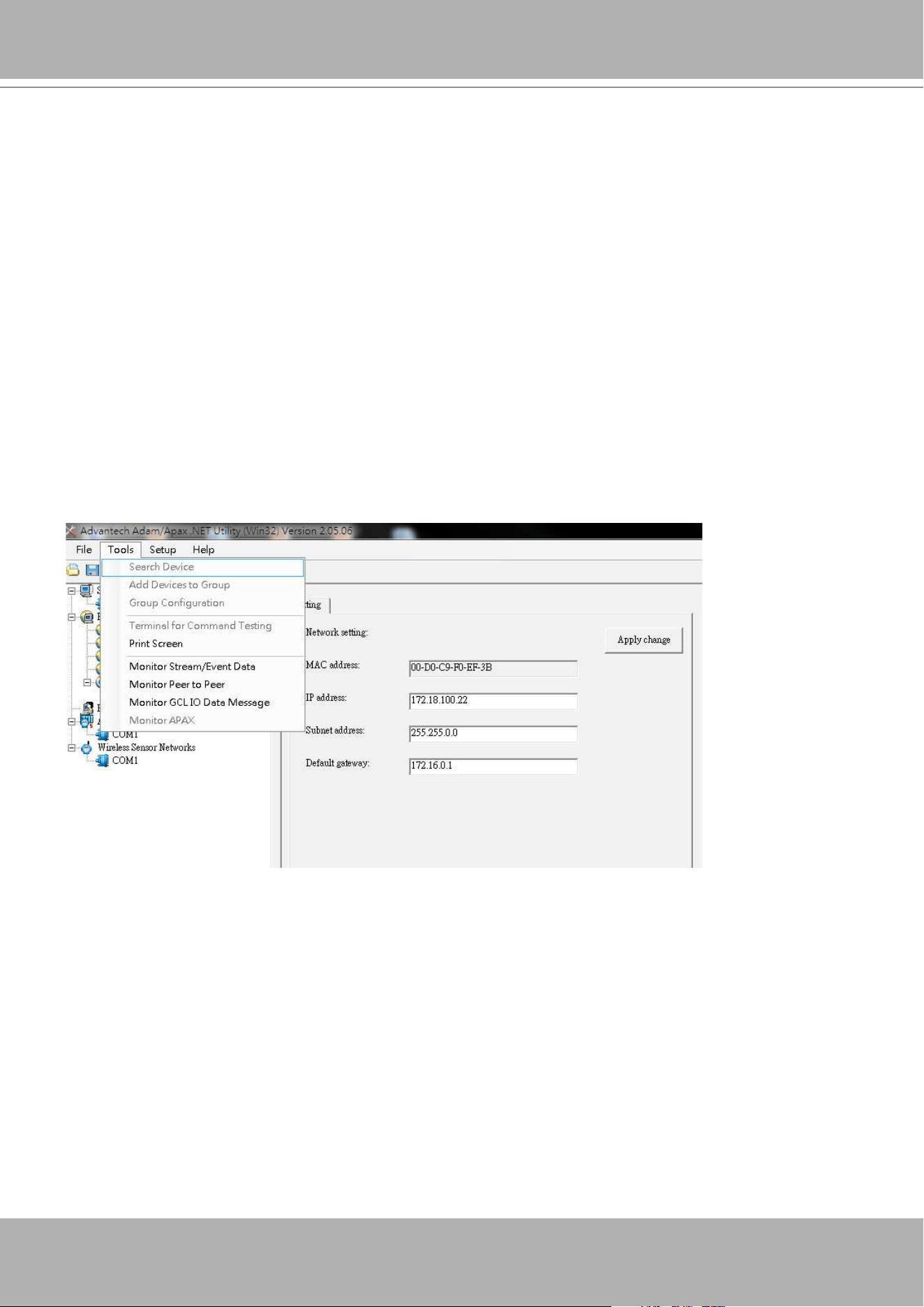
VIVOTEK - A Leading Provider of Multimedia Communication Solutions
User's Manual - 357
Appendix E Support for Digital I/O Modbus TCP
Modules
This revision, rev. 1.9, supports Advantech's I/O Modbus TCP Modules 6000 series. The VAST
server can receive digital inputs and trigger digital outputs via the I/O modules.
The Advantech I/O modules come with configuration utilities, such as the Adam/Apax.NET.
Connect the DI/DO wires to the module and the Ethernet wire from the module to the local
network.
Proceed with the following to congure the I/O module:
1. Use the Search function to locate the I/O module on the network.
2. It is recommended to congure a static IP for the I/O module.
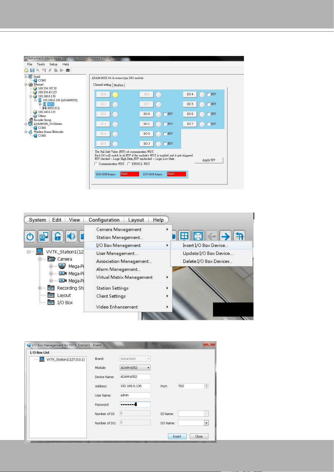
VIVOTEK - A Leading Provider of Multimedia Communication Solutions
358 - User's Manual
3. You may then test the DI/DO device connectivity using the software utility.
4. To congure the I/O modules in VAST, open the
Conguration
>
I/O Box Management
>
Insert I/O Box Device
window.
5. Select the Module model name, enter IP address, User Name, Password, and then click the
Insert button.
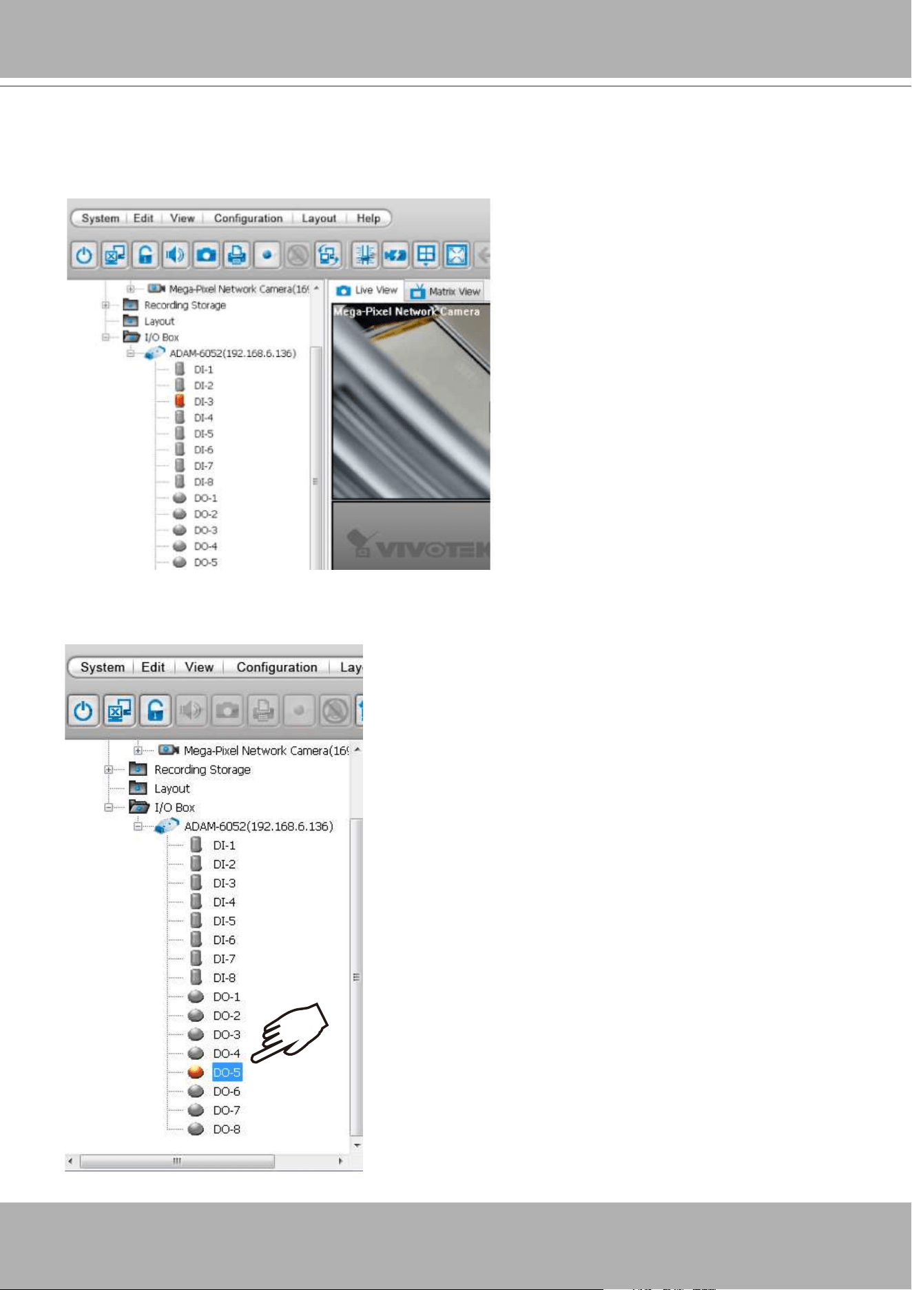
VIVOTEK - A Leading Provider of Multimedia Communication Solutions
User's Manual - 359
6. Click Close to close the window. The I/O module and its DI/DO entries should be listed on the
device tree under the I/O box sub-directory. As shown below, once a DI is triggered from the
I/O module, the associated DI icon will be lighted. Audible notication can also be heard from
the VAST server.
x2
7. You can also double-click on a DO icon to manually trigger the digital output. Double-click
again to cancel the trigger.
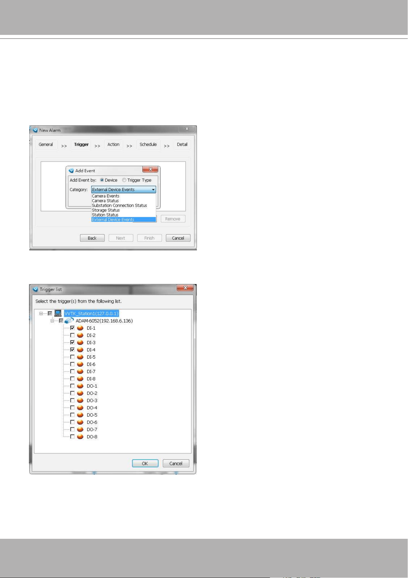
VIVOTEK - A Leading Provider of Multimedia Communication Solutions
360 - User's Manual
8. You can also implement the digital inputs and outputs from the I/O module in your alarm
setting. For example, a DI can be wired to an intrusion detector; and when the DI is triggered,
an associated DO can be used to sound an alarm.
To configure the Alarm setting, enter the
Configuration
>
Alarm management
window.
Configure a new alarm. On the Trigger window, select the Trigger Category as
External
Device Events
.
9. The DIs and DOs on the I/O module will be listed. You can then select one or more DIs as the
triggers.
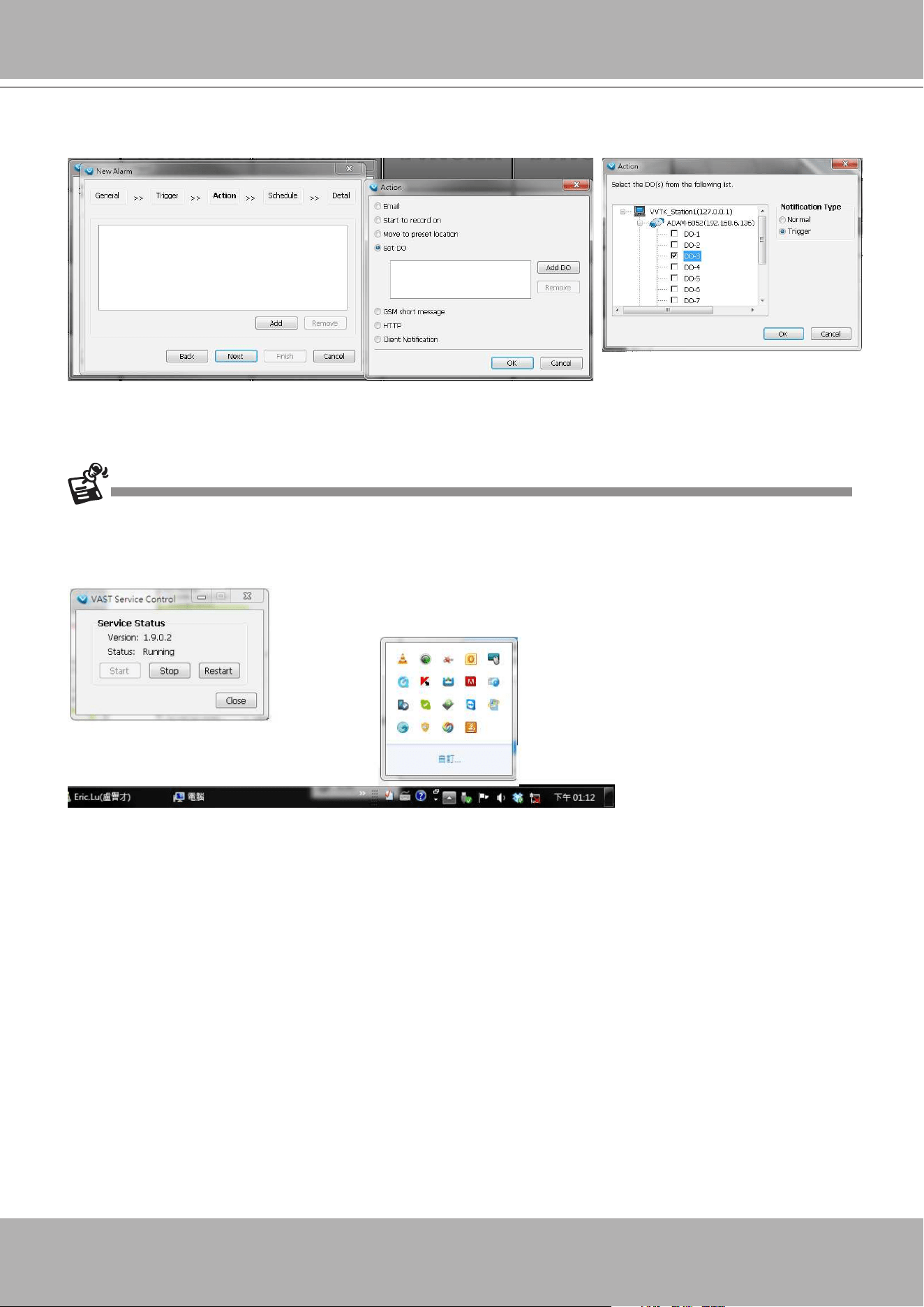
VIVOTEK - A Leading Provider of Multimedia Communication Solutions
User's Manual - 361
10. On the Action panel, you can select to trigger DOs, for example, as the reacting actions
Note that once a DO is triggered, you should manually disable the DO.
If an I/O module is started later than the VAST server, you may not be able to access the I/O module.
You should then re-start the VAST service.
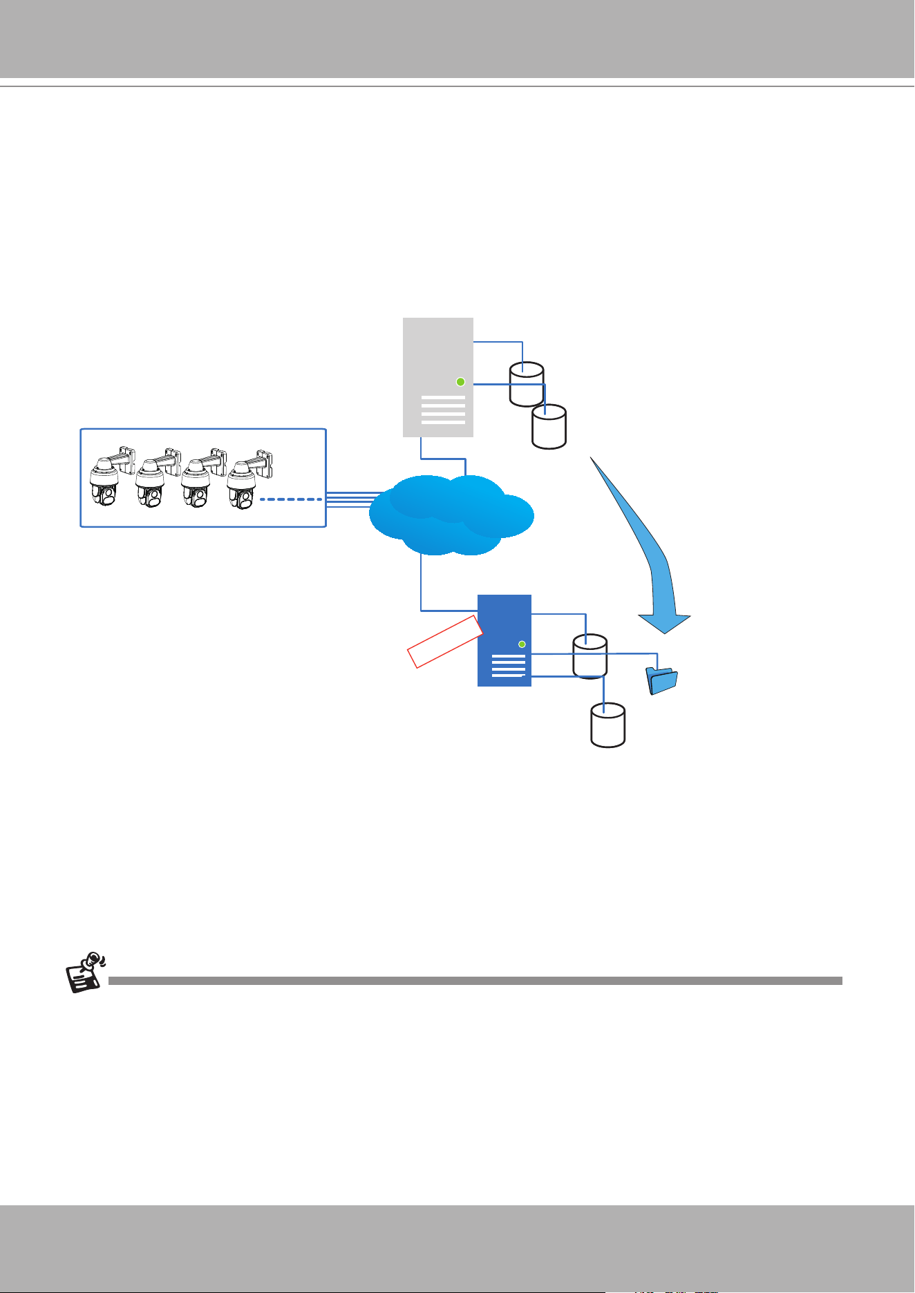
VIVOTEK - A Leading Provider of Multimedia Communication Solutions
362 - User's Manual
Appendix F Database Merge Function
The Database Merge function applies in the following scenario:
1. A VAST server A failed or was intentionally depleted. The precondition is that the disk drives
containing the recordings remain intact.
VAST server B
VAST Server A
Network Cameras
LAN
DB
Recorded
videos (default path)
DB
Recorded
videos
Failed
Taken over
Recovery path
2. The VAST server B is used to continue video recording. The previous recordings on server A
can be retrieved by attaching the hard disk(s) to server B or manually copying to a storage
device on server B. You can then designate the location of these files as the "Recovery
path" from server B. An administrator can then use the VAST Playback to access the past
recordings.
Note that you can also congure a separate recycle policy for that Recovery path.
• It is
IMPORTANT
to move or copy the entire storage group folder, e.g.,
D:/recording/2016-
06-17/1-FE9181-H..., which is a root directory congured by VAST server as the recording
folder. The default recording folder contains file folder structure, video files, and database
metadata. If you copy the video les only, the database data will not be synchronized, and
you will not be able to access the recordings using the VAST Playback utility.
• The video streams received from cameras will not be recorded on to the Recovery path
folder. It is designed to maintain previous recordings. The Recovery path folder becomes
static.
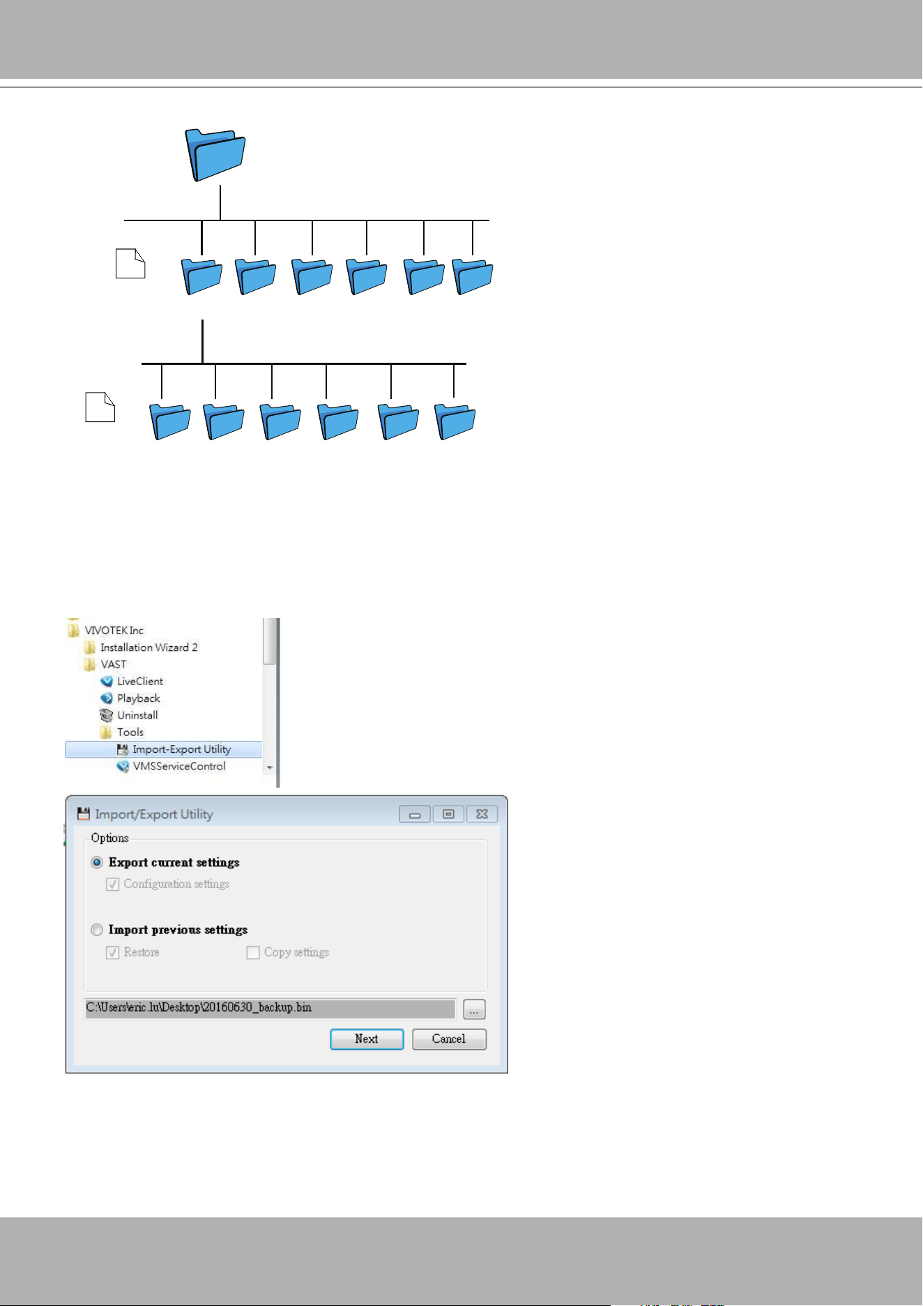
VIVOTEK - A Leading Provider of Multimedia Communication Solutions
User's Manual - 363
D:/Record
2016-06-17 2016-06-18 2016-06-19 2016-06-20 2016-06-21
2016-06-22
Recording Doc
1-FE9181-H 2-FD9381 3-Outdoor
Speed Dome
4-Outdor
Speed Dome
5-IB9381 6-IP8166
2016-06-17
. . . .
. . . .
• It is also a good habit to export and preserve your VAST system configuration to prevent
losses in the event of system failure. In case you want to migrate or upgrade your VAST
server, you can use the Import-Export utility to duplicate your VAST configuration to
another server. Copy the conguration le and import the conguration from another VAST
server.
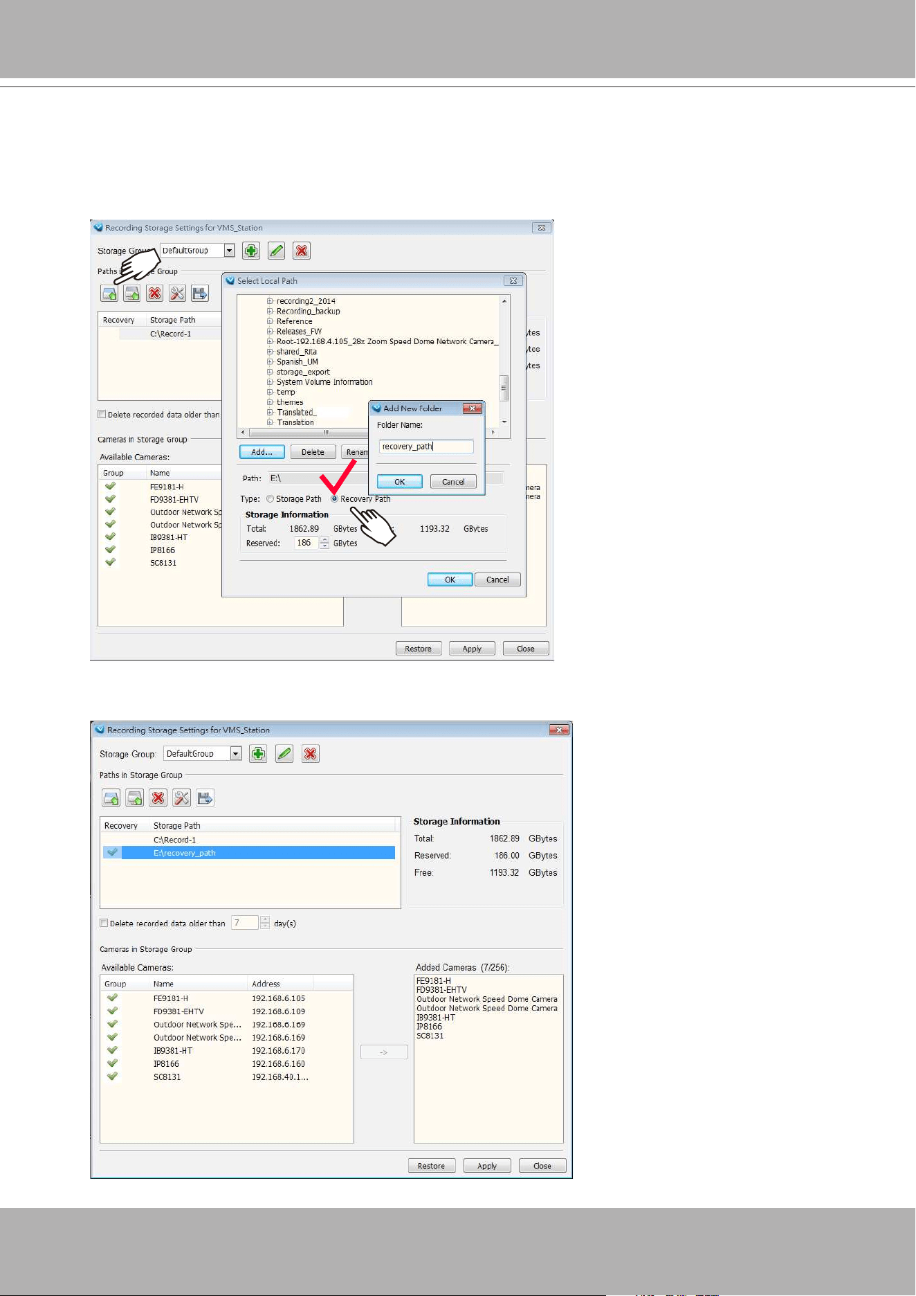
VIVOTEK - A Leading Provider of Multimedia Communication Solutions
364 - User's Manual
When the file folder is ready for server B, designate the location of recovered files from
another VAST server, go to Conguration > Station Settings > Recording Storage Settings.
Click the Apply and Close button.
Select the recording folder that contains the recordings from the counterpart VAST server.
Select the
Recovery Path
check circle and click
OK
.
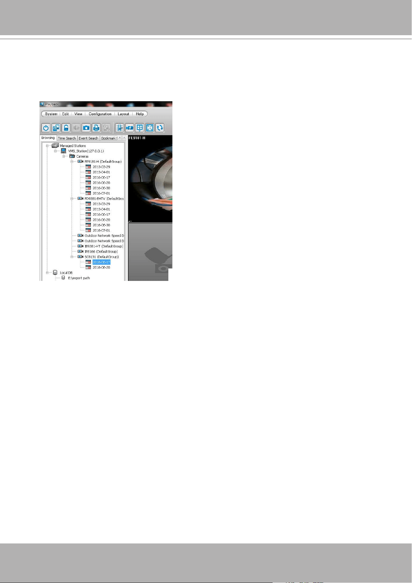
VIVOTEK - A Leading Provider of Multimedia Communication Solutions
User's Manual - 365
If you are running the
Playback
utility, close and re-start the Playback utility. Open the device
tree, and you should be able to see previous recordings listed under each camera. This
indicates previous recordings can be accessed from the recovery path and the databases on
the two VAST instances have been synchronized.
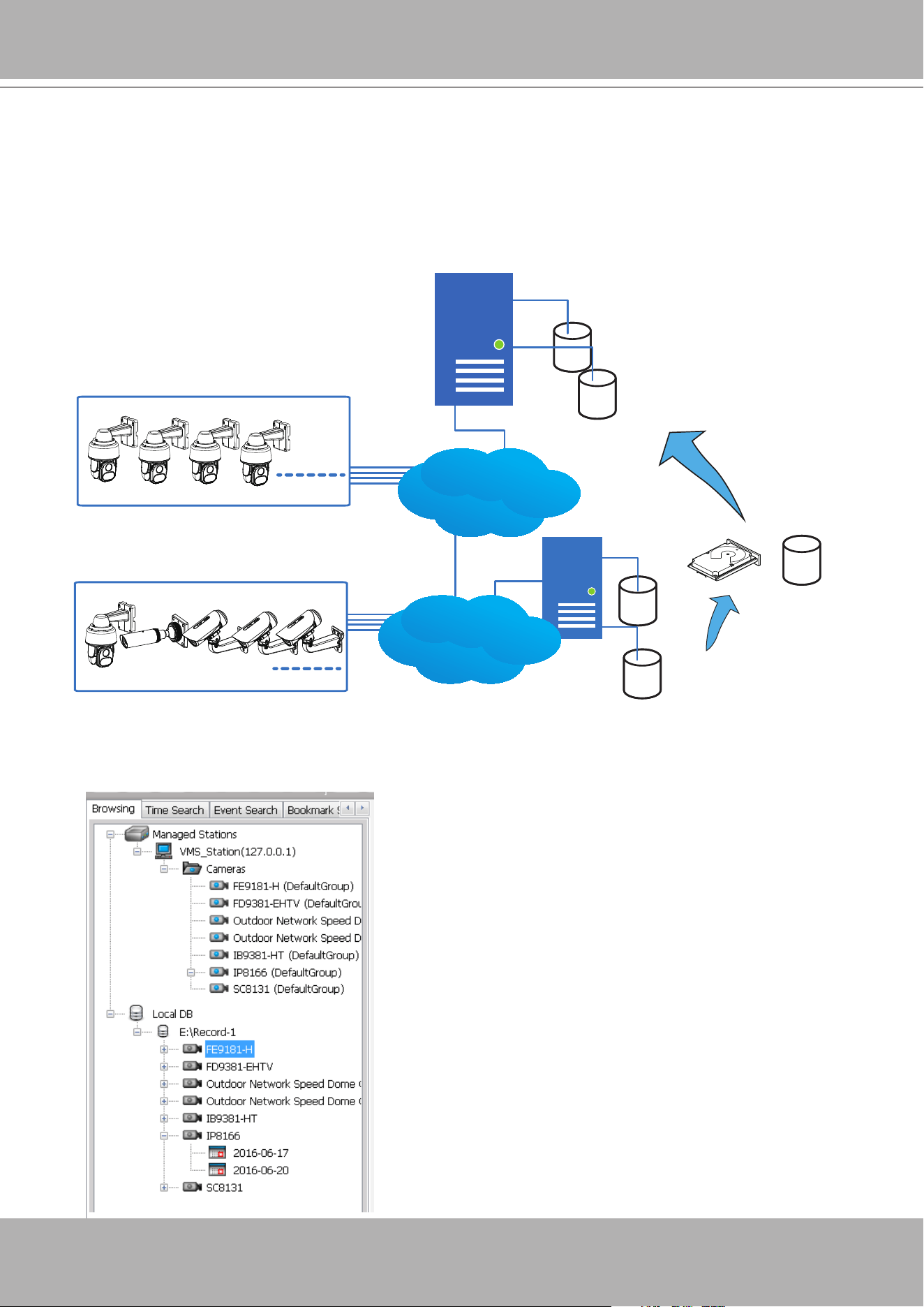
VIVOTEK - A Leading Provider of Multimedia Communication Solutions
366 - User's Manual
In addition to the use of Recovery path, if you need to access the recordings made by a
different VAST server, you can also manually copy the entire storage group folder, such as
D:/recording, to a hard drive or a network share, and then avail the recordings on the new
server.
Different from the use of Recovery Path (Database Merge), this scenario applies to two VAST
servers with different congurations.
VAST server B
VAST Server A
Network Cameras
LAN
DB
Recorded
videos
DB
Recorded
videos
HDD Network share
- or -
Network Cameras
LAN
(Entire folder)
On the Playback window, right-click the Local DB icon to display the
Add
command. Select
the folder where the recordings reside. The recordings should be listed under each of the
cameras.
Note that as the folder structure remains intact, you
can still manually remove some of the video files
within, if they are not of your interest.
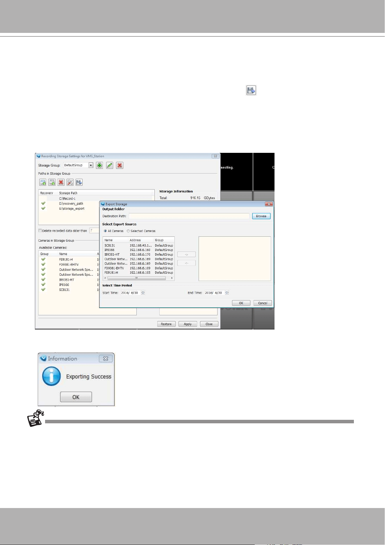
VIVOTEK - A Leading Provider of Multimedia Communication Solutions
User's Manual - 367
The
Export Storage
is another backup function.
To export video recordings to a specic target folder, enter Conguration > Station Settings >
Recording Storage Settings. Click the Browse button to select a target folder.
Select the default storage group, click on the
Export
button . Select all cameras (default)
or manually select specic cameras from the list. If you want to select individual cameras, use
the arrow buttons to move cameras to the right column. Select the time span of the export
using the selectors below. The minimum span is one day. Click OK to proceed.
Note that the videos thus exported can not be indexed in the Playback utility's device list.
Each video clip should be watched individually.
Depending on the length of time span and the number of selected cameras, the export
process may take several minutes or longer to complete.
• If the members of the original VAST conguration (cameras) have been changed, the VAST
server will not be able to locate the original MAC addresses, and may not be able to retrieve
past recordings.
• The
Export Storage
function only takes effect on the VAST server local console. It is not
available on a web console.
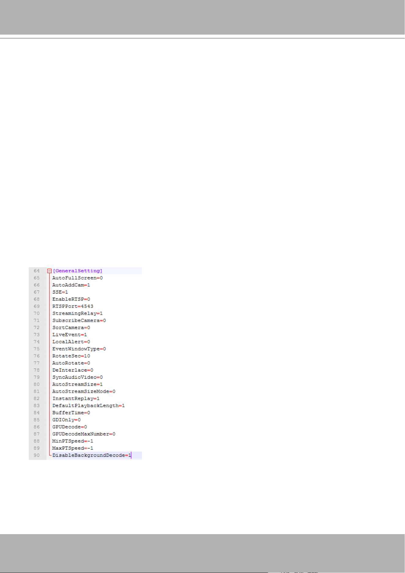
VIVOTEK - A Leading Provider of Multimedia Communication Solutions
368 - User's Manual
Appendix G Other Parameters
Disable background decode:
Administrators can choose to disable the background decode for other view cells when entering
a single view of a specific camera. This can help reduce the CPU load on a server short of
system resources.
This function can be evaluated in two aspects:
1. For a server with abundant system resources, there is less stress when disabling and
enabling background decode. When a user leaves a single view and enters a multi-cell
view, the background decode starts again, and a powerful server handles this process more
smoothly.
2. For a server with less resources, this feature can reduce CPU load. However, latency can
occur during the process when returning from a single view back to a multi-cell view.
This feature is enabled by editing the ClientSetting.ini file in
C:\ProgramData\VIVOTEK Inc\
VAST\Client\LiveClient.