
Operator’s Manual
Warning: This unit is equipped with an internal combustion engine and should not be used on or near any unimproved forest-covered, brush-
covered or grass-covered land unless the engine’s exhaust system is equipped with a spark arrester meeting applicable local or state laws (if any).
If a spark arrester is used, it should be maintained in effective working order by the operator. In the State of California the above is required by law
(Section 4442 of the California Public Resources Code). Other states may have similar laws. Federal laws apply on federal lands. A spark arrester
for the muffler is available by contacting the service department at Troy-Bilt LLC, P.O. Box 361131 Cleveland, Ohio 44136-0019.
IMPORTANT:READ SAFETY RULES AND INSTRUCTIONS CAREFULLY
TROY-BILT LLC, P.O. BOX 361131, CLEVELAND, OH 44136-0019
PRINTED IN USA FROM NO. 769-00586
(12/2002)
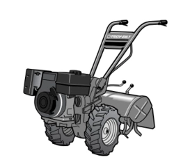
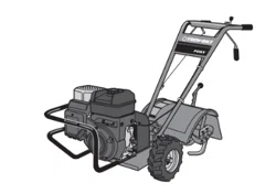
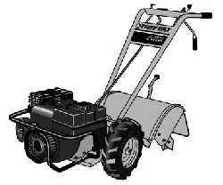
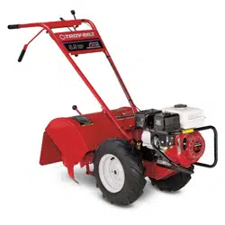
Model 675B Shown (bumper syles vary)
Rear-tine Tiller Model
675B—Pony
®
2
For more details about your unit, visit our website at www.troybilt.com
TABLE OF CONTENTS
Content Page
Calling Customer Support . . . . . . . . . . . . . . . . . . . . . . . . . . . . . . . . . . . . . . . . . . . . . . . . . . . . 2
Safety . . . . . . . . . . . . . . . . . . . . . . . . . . . . . . . . . . . . . . . . . . . . . . . . . . . . . . . . . . . . . . . . . . . 3
Assembly. . . . . . . . . . . . . . . . . . . . . . . . . . . . . . . . . . . . . . . . . . . . . . . . . . . . . . . . . . . . . . . . . 6
Features and Controls. . . . . . . . . . . . . . . . . . . . . . . . . . . . . . . . . . . . . . . . . . . . . . . . . . . . . . . 8
Operation . . . . . . . . . . . . . . . . . . . . . . . . . . . . . . . . . . . . . . . . . . . . . . . . . . . . . . . . . . . . . . . . 11
Maintenance . . . . . . . . . . . . . . . . . . . . . . . . . . . . . . . . . . . . . . . . . . . . . . . . . . . . . . . . . . . . . . 16
Troubleshooting . . . . . . . . . . . . . . . . . . . . . . . . . . . . . . . . . . . . . . . . . . . . . . . . . . . . . . . . . . . 22
Parts List . . . . . . . . . . . . . . . . . . . . . . . . . . . . . . . . . . . . . . . . . . . . . . . . . . . . . . . . . . . . . . . . . 24
Warrany Information . . . . . . . . . . . . . . . . . . . . . . . . . . . . . . . . . . . . . . . . . . . . . . . . . . . . . . . . Back Cover
FINDING MODEL NUMBER
This Operator’s Manual is an important part of your new Rear-tine Tiller. It will help you assemble, prepare and main-
tain the unit for best performance. Please read and understand what it says.
Before you start assembling your new equipment, please locate the model plate on the equipment and copy the infor-
mation from it in the space provided below. This information is very important if you need help from our Customer
Support Department or an authorized dealer.
• You can locate the model number by looking at the rear surface of the tine shield. A sample model plate is
explained below. For future reference, please copy the model number and the serial number of the equipment
in the space below
ENGINE INFORMATION
The engine manufacturer is responsible for all engine-related issues with regards to performance, power-rating, speci-
fications, warranty and service. Please refer to the engine manufacturer’s Owner’s/Operator’s Manual packed sepa-
rately with your unit for more information.
CALLING CUSTOMER SUPPORT
If you have difficulty assembling this product or have any questions regarding the controls, operation or maintenance
of this unit, please call the Customer Support Department.
Call
1- (330) 558-7220 or 1- (866) 840-6483 to reach a Customer Support representative. Please have
your unit’s model number and serial number ready when you call. See previous section to locate this infor-
mation. You will be asked to enter the serial number in order to process your call .
Copy Model Number Here
Copy Serial Number Here
www.troybilt.com
TROY-BILT LLC
P. O. BOX
361131
CLEVELAND, OH 44136
866-840-6483
330-558-7220
Safety
1
Section
3
Training
1. Carefully read this Owner’s
Manual, the separate Engine
Owner’s Manual, and any
other literature you may receive. Be thor-
oughly familiar with the controls and the
proper use of the tiller and its engine.
Know how to stop the unit and disengage
the controls quickly.
2. Never allow children to operate the
tiller. Never allow adults to operate the
tiller without proper instruction.
3. Keep the area of operation clear of all
persons, particularly children and pets.
4. Keep in mind that the operator or user
is responsible for accidents or hazards
occurring to other people, their property,
and themselves.
Preparation
1. Thoroughly inspect the area where the
tiller is to be used and remove all foreign
objects.
2. Be sure all control levers are released
and the Wheel Gear Lever is in ENGAGE
position before starting the engine.
3. Do not operate the tiller without
wearing adequate outer garments. Avoid
loose garments or jewelry that could get
caught in moving parts.
4. Do not operate the tiller when barefoot or
wearing sandals, sneakers, or light
footwear. Wear protective footwear that will
improve footing on slippery surfaces.
5. Do not till near underground electric
cables, telephone lines, pipes or hoses. If in
doubt, contact your telephone or utility
company.
6. Warning: Handle fuel with care; it is
highly flammable and its vapors are explo-
sive. Take the following precautions:
a. Store fuel in containers specifically
designed for this purpose.
b. The gas cap shall never be removed
or fuel added while the engine is
running. Allow the engine to cool
for several minutes before adding
fuel.
c. Keep matches, cigarettes, cigars,
pipes, open flames, and sparks
away from the fuel tank and fuel
container.
d. Fill fuel tank outdoors with extreme
care. Never fill fuel tank indoors.
Use a funnel or spout to prevent
spillage.
e. Replace all fuel tank and container
caps securely.
f. If fuel is spilled, do not attempt to
start the engine, but move the
machine away from the area of
spillage and avoid creating any
source of ignition until fuel vapors
have dissipated.
7. Never make adjustments when engine
is running (unless recommended by
manufacturer).
Operation
1. Do not put hands or feet near or under
rotating parts.
2. Exercise extreme caution when on or
crossing gravel drives, walks, or roads.
Stay alert for hidden hazards or traffic. Do
not carry passengers.
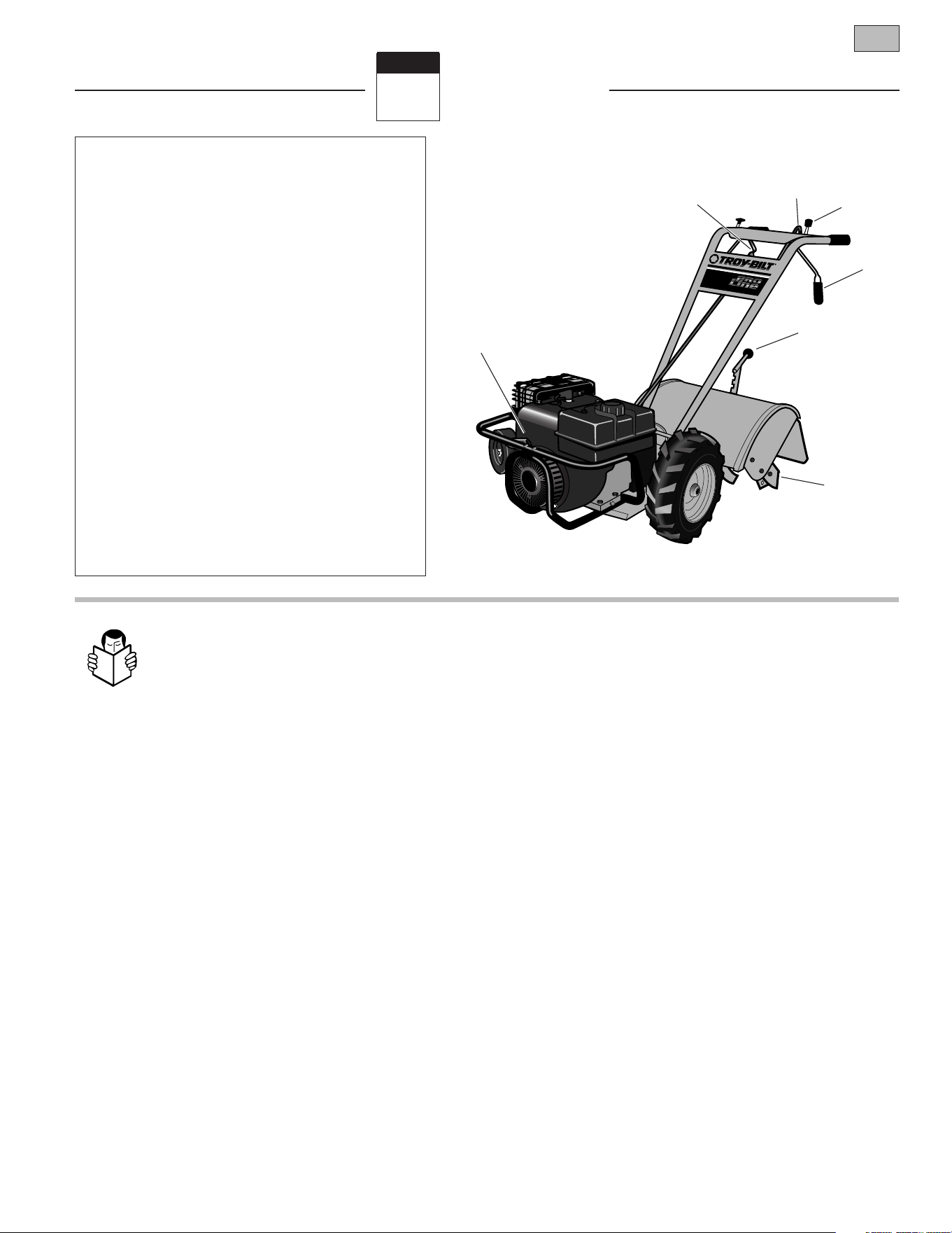
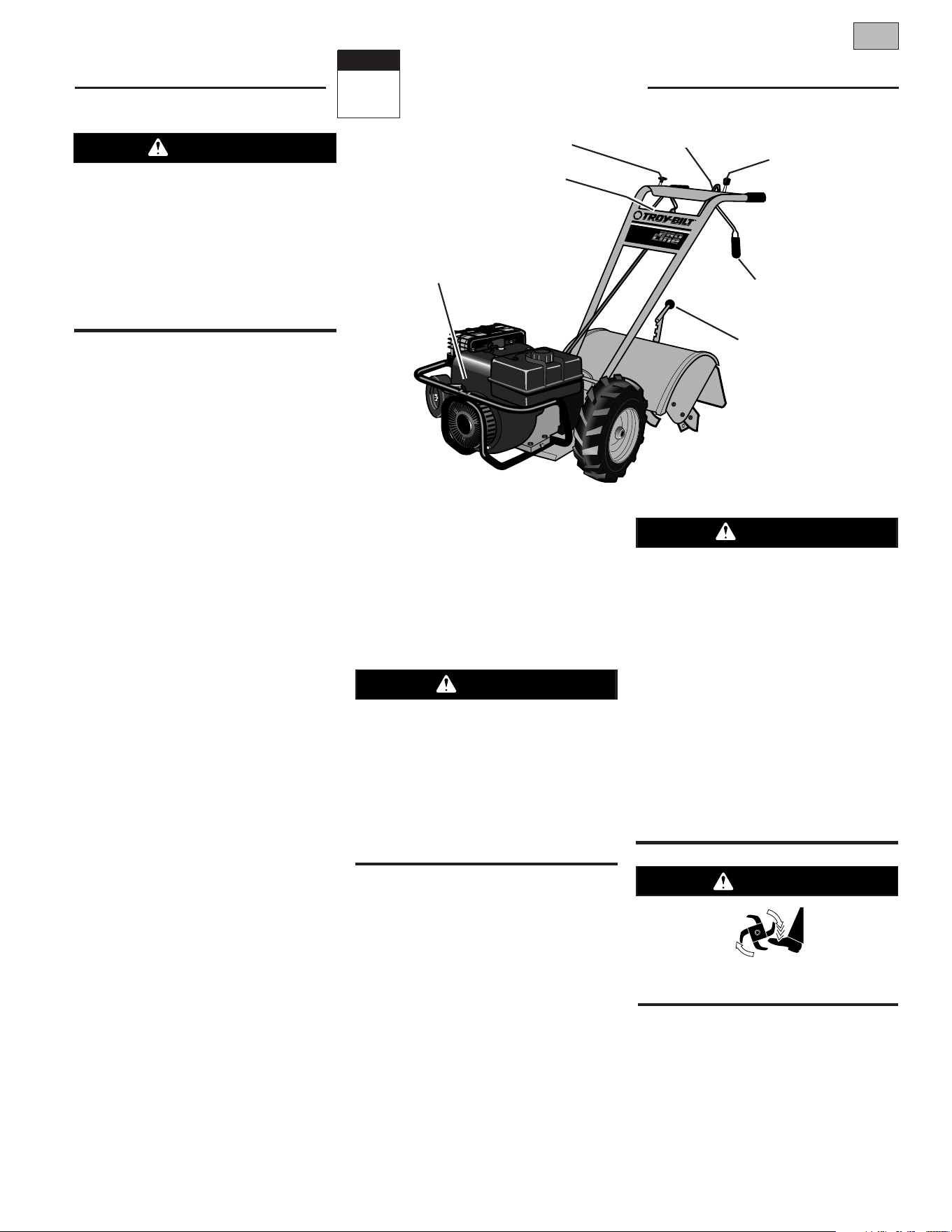
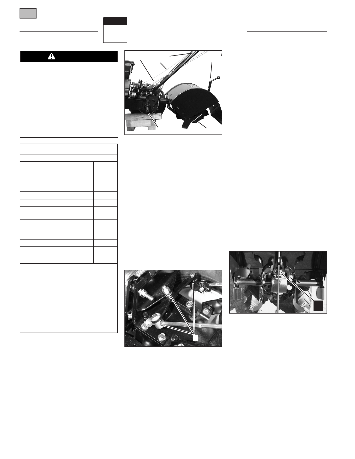
Figure 1-1
Reverse
Clutch
Control
Forward
Clutch
Lever
Forward Clutch
Lever
Depth
Regulator
Lever
Counter
Rotating
Tines
Wheel Gear
Lever
Recoil Rope
Starter
SPARK ARRESTER WARNING TO RESIDENTS OF
CALIFORNIA AND SEVERAL OTHER STATES
Under California law, and under the laws of several
other states, you are not permitted to operate an inter-
nal combustion engine using hydrocarbon fuels on any
forest, brush, hay, grain, or grass covered land; or land
covered by any flammable agricultural crop without an
engine spark arrester in continuous effective working
order.
The engine on the unit is an internal combustion engine
which burns gasoline, a hydrocarbon fuel, and must be
equipped with a spark arrester muffler in continuous
effective working order. The spark arrester must be
attached to the engine exhaust system in such a
manner that flames or heat from the system will not
ignite flammable material. Failure of the owner/opera-
tor of the unit to comply with this regulation is a mis-
demeanor under California law (and other states) and
may also be a violation of other state and/or federal
regulations, laws, ordinances or codes. Contact your
local fire marshal or forest service for specific informa-
tion about which regulations apply in your area.

4 Section 1: Safety
3. After striking a foreign object, stop the
engine, remove the wire from the ,spark
plug wire and prevent it from touching the
spark plug, thoroughly inspect the
machine for any damage, and repair the
damage before restarting and operating
the machine.
4. Exercise caution to avoid slipping or
falling.
5. If the unit should start to vibrate abnor-
mally, stop the engine, disconnect the spark
plug wire and prevent it from touching the
spark plug, and check immediately for the
cause. Vibration is generally a warning of
trouble.
6. Stop the engine, disconnect the spark
plug wire and prevent it from touching the
spark plug whenever you leave the operat-
ing position, before unclogging the tines,
or when making any repairs, adjustments
or inspections.
7. Take all possible precautions when
leaving the machine unattended. Stop the
engine. Disconnect spark plug wire and
move it away from the spark plug. Move
Wheel Gear Lever to ENGAGE.
8. Before cleaning, repairing, or inspect-
ing, stop the engine and make certain all
moving parts have stopped. Disconnect
the spark plug wire and prevent it from
touching the spark plug to prevent acci-
dental starting.
9. Always keep the tiller tine hood flap
down.
10. Never use the tiller unless proper
guards, plates, or other safety protective
devices are in place.
11. Do not run engine in an enclosed area.
Engine exhaust contains carbon monoxide
gas, a deadly poison that is odorless, col-
orless, and tasteless.
12. Keep children and pets away.
13. Never operate the tiller under engine
power if the Wheel Gear Lever is in DIS-
ENGAGE (FREEWHEEL). In this position,
the wheels will not hold the tiller back
and the revolving tines could propel the
tiller rapidly backward, possibly causing
loss of control.
Always move the Wheel
Gear Lever to ENGAGE before starting the
engine or engaging the tines/wheels with
the Forward Clutch or the Reverse Clutch.
14. Be aware that the tiller may unexpect-
edly bounce upward or jump backward if
the tines should strike extremely hard
packed soil, frozen ground, or buried
obstacles like large stones, roots, or
stumps. If in doubt about the tilling condi-
tions, always use the following operating
precautions to assist you in maintaining
control of the tiller:
a. Walk behind and to one side of the
tiller, using one hand on the han-
dlebars. Relax your arm, but use a
secure hand grip.
b. Use slower engine speeds.
c. Clear the tilling area of all large
stones, roots and other debris.
d. Avoid using downward pressure on
handlebars. If need be, use slight
upward pressure to keep the tines
from digging too deeply.
e. Before contacting hard packed soil
at the end of a row, reduce engine
speed and lift handlebars to raise
tines out of the soil.
f. In an emergency, stop tines and
wheels by releasing whichever
Clutch Lever is engaged. Do not
attempt to restrain the tiller.
15.
Do not overload the tiller’s capacity by
attempting to till too deeply at too fast a
rate.
16. Never operate the tiller at high trans-
port speeds on slippery surfaces. Look
behind and use care when backing up.
17. Do not operate the tiller on a slope
that is too steep for safety. When on
slopes, slow down and make sure you
have good footing. Never permit the tiller
to freewheel down slopes.
18. Never allow bystanders near the unit.
19. Only use attachments and accessories
that are approved by Garden Way Inc.
20. Use tiller attachments and accessories
when recommended.
21. Never operate the tiller without good
visibility or light.
22. Never operate the tiller if you are tired, or
under the influence of alcohol, drugs or
medication.
23. Operators shall not tamper with the
engine-governor settings on the machine;
the governor controls the maximum safe
operating speed to protect the engine and all
moving parts from damage caused by over-
speed. Authorized service shall be sought if
a problem exists.
24. Do not touch engine parts which may be
hot from operation. Let parts cool down
sufficiently.
25. Please remember: You can always stop
the tines and wheels by releasing the
Forward Clutch Lever or the Reverse Clutch
Control (whichever lever you have engaged)
or by moving the Throttle Control Lever to
STOP.
26. To load or unload the tiller, see the
instructions in Section 4 of this Manual.
27. Use extreme caution when reversing or
pulling the machine towards you.
28. Start the engine carefully according to
instructions and with feet well away from the
tines.
29. Never pick up or carry a machine while
the engine is running.
Maintenance and Storage
1. Keep the tiller, attachments and acces-
sories in safe working condition.
2. Check all nuts, bolts, and screws at fre-
quent intervals for proper tightness to be
sure the equipment is in safe working con-
dition.
3. Never store the tiller with fuel in the fuel
tank inside a building where ignition sources
are present such as hot water and space
heaters, furnaces, clothes dryers, stoves,
electric motors, etc.). Allow engine to cool
before storing in any enclosure.
4. To reduce the chances of a fire hazard,
keep the engine free of grass, leaves, or
excessive grease.
5. Store gasoline in a cool, well-ventilated
area, safely away from any spark- or flame-
producing equipment. Store gasoline in an
approved container, safely away from the
reach of children.
6. Refer to the storage instructions in the
Maintenance section of this Manual and
the separate Engine Owner’s Manual for
instructions if the tiller is to be stored for
an extended period.
7. Never perform maintenance while the
engine is running or the spark plug wire is
connected, except when specifically
instructed to do so.
8. If the fuel tank has to be drained, do this
outdoors.
Section 1: Safety 5
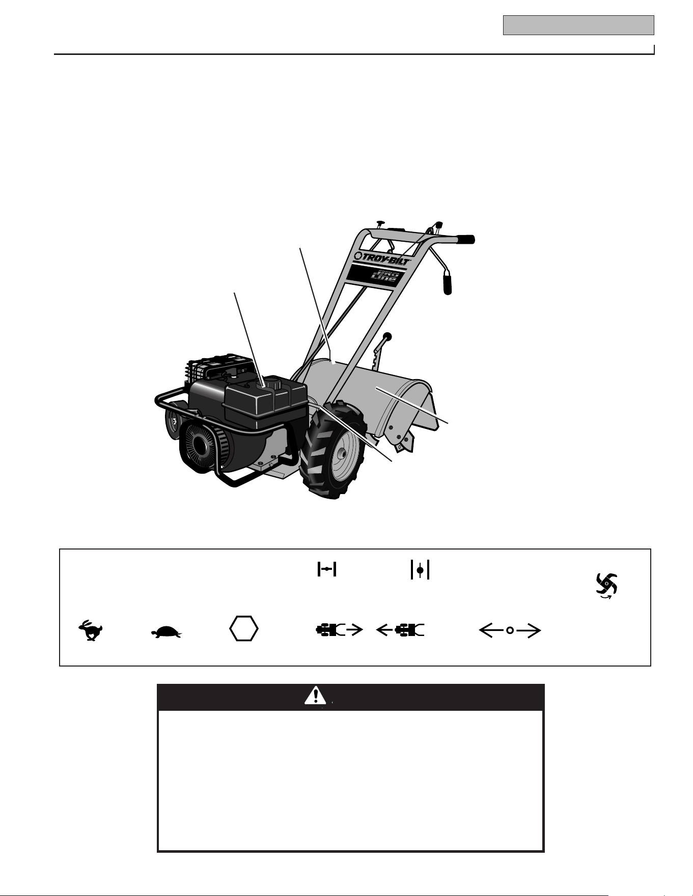
Control Descriptions
(on control Panel)
Warning Messages
(on tine hood)
Tine Warning
(on right side of
hood flap)
Hot Surfaces/Moving Belts
Warning (on belt cover)
Starting Stabilization
Message (on engine)
Figure 1-2: Location of Safety and Operating Decals
TO AVOID SERIOUS INJURY:
• READ THE OWNER’S MANUAL.
• KNOW LOCATIONS AND FUNCTIONS OF ALL CONTROLS.
• KEEP ALL SAFETY DEVICES AND SHIELDS IN PLACE AND WORKING.
• NEVER ALLOW CHILDREN OR UNINSTRUCTED ADULTS TO OPERATE TILLER.
• SHUT OFF ENGINE AND DISCONNECT SPARK PLUG WIRE BEFORE MANUALLY UNCLOG-
GING TINES OR MAKING REPAIRS.
• KEEP BYSTANDERS AWAY FROM MACHINE.
• KEEP AWAY FROM ROTATING PARTS.
• USE EXTREME CAUTION WHEN REVERSING OR PULLING THE MACHINE TOWARDS YOU.
WARNING
Operating Symbols
Various symbols (shown here, with word
descriptions) may be used on the tiller and
engine.
FAST
SLOW
CHOKE
ON
CHOKE
OFF
STOP
STOP
REVERSE
R
ROTATING
TINES
TILLER DIRECTION
LEVER DIRECTION
Safety Decals
For your safety and the safety of others,
various safety and operational decals are
located on your unit (see Figure 1-2
below).
Keep the decals clean and legible at all
times. Contact your local service dealer or
the factory for replacements if any decals
are damaged or missing.
Refer to the Parts List in this manual for
decal locations, part numbers and order-
ing instructions.
Assembly
2
Section
6
INTRODUCTION
Carefully follow these assembly steps to
correctly prepare your tiller for use. It is
recommended that you read this Section
in its entirety before beginning assembly.
INSPECT UNIT
Inspect the unit and carton for damage
immediately after delivery. Contact the
carrier (trucking company) if you find or
suspect damage. Inform them of the
damage and request instructions for filing
a claim. To protect your rights, put your
claim in writing and mail a copy to the
carrier within 15 days after the unit has
been delivered. Contact us at the factory if
you need assistance in this matter.
UNPACKING AND ASSEMBLY
INSTRUCTIONS
STEP 1: UNPACKING INSTRUCTIONS
1. Remove any cardboard inserts and
packaging material from the carton.
Remove any staples from the bottom of
the carton and remove the carton.
2. Cut the large, plastic tie strap that
secures the transmission tube to the ship-
ping pallet. Leave the handlebars on top of
the tiller to avoid damaging any cables.
3. A bag with loose hardware is inside the
literature envelope. Check the contents
against the following list and Figure 2-1.
Contact your local dealer or the factory if
any items are missing or damaged.
NOTE: For electric start units, a second
hardware bag is located near the battery.
4. The tiller is heavy. You should not
attempt to remove it from the shipping
platform until instructed to do so in these
“Assembly” steps.
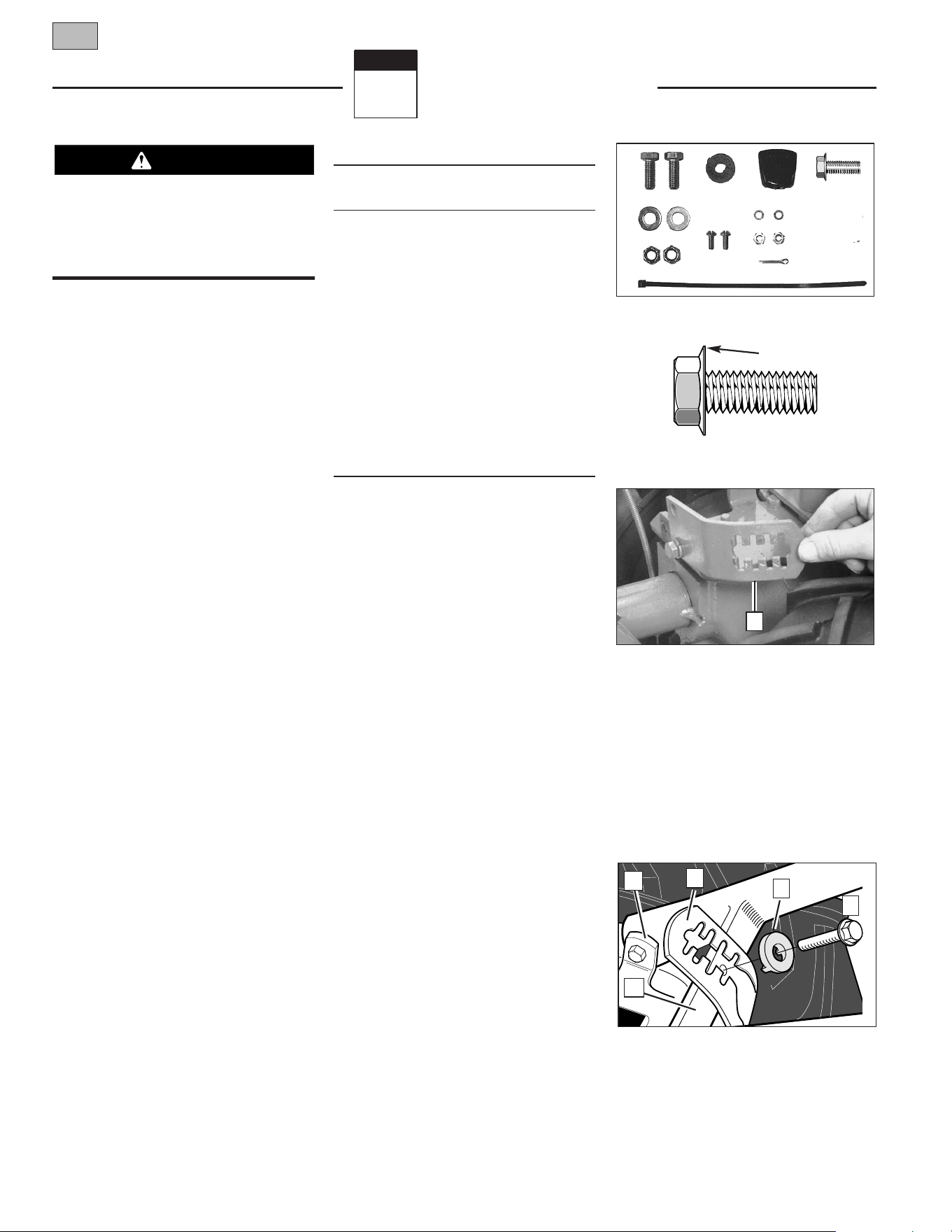
HARDWARE BAG PARTS LIST
Fig.
Ref. Qty. Description
1
2 3/8-16 x 1" Hex Hd. Screw
2 1 Keyed Washer
3 1 Wheel Gear Lever Knob
4 1 Height Adjustment Flange
Screw (See Figure 2-1A)
5 2 3/8" Flat Washer
6 2 #10 Lockwasher
7 2 3/8"-16 Nylock Lock Nut
8 2 #10-32 x 1/2" Round Hd.
Screw
9 2 #10-32 Nut
10 1 Cotter Pin (not used)
11 4 Plastic Tie Strap (2 not used)
Tools/Materials Needed
for Assembly
(1) 3/8" open-end wrench*
(1) 7/16" open-end wrench* (electric
start unit only)
(2) 9/16" open-end wrench*
(1) 7/8" open-end wrench or 8" long
adjustable wrench
(1) Scissors (to trim plastic ties)
(1) Ruler
(1) Small board (to tap plastic knob on
lever)
(1) Tire pressure gauge
(1) Clean oil funnel
(1) Clean, high-quality motor oil. Refer to
the separate Engine Owner’s Manual
for motor oil specifications and quan-
tity required.
* Adjustable wrenches may be used.
IMPORTANT: Motor oil must be added to
the engine crankcase before the engine is
started. Follow the instructions in this
“Assembly” Section and in the separate
Engine Owner’s Manual.
NOTE: LEFT and RIGHT sides of the tiller
are as viewed from the operator’s position
behind the handlebars.
STEP 2: ATTACH HANDLEBARS
1. On electric start units, remove one
screw and lockwasher from the curved
height adjustment bracket (A, Figure 2-2),
loosen the second screw, and swing the
bracket to one side.
2. Cut the large, plastic cable ties that
secure the handlebar ends to the handle-
bar mounting tabs on the transmission
top cover.
3. Gently lift handlebar (do not over-
stretch attached cable) and place handle-
bar cross-brace (B, Figure 2-3) in front of
curved height adjustment bracket (C).
To prevent personal injury or property
damage, do not start the engine until all
assembly steps are complete and you
have read and understand the safety and
operating instructions in this Manual.
WARNING
Figure 2-2: On electric start units, move
height adjustment bracket aside.
Figure 2-3: Forward clutch control cable not
shown for clarity.
Figure 2-1: Loose hardware (shown in
reduced size).
Figure 2-1A Handlebar height adjustment
uses the flange head screw.
31
2
4
5
6
11
7
8
9
E
F
A
C
Flange
10
B
M
Section 2: Assembly 7
4. With the forward clutch cable (N,
Figure 2-4) on the inside of handlebar,
position the handlebar ends on the outside
of the two mounting tabs (M, Figure 2-3)
on the transmission top cover.
NOTE: The curved handlebar height
adjustment bracket appears as shown in
C, Figure 2-3 for non-electric start units.
For electric start units, the bracket is loos-
ened and moved to one side.
5. Loosely attach the handlebars to the
mounting tabs with two 3/8-16 x 1"
screws (heads of screws go to inside of
tabs), 3/8" flat washers and 3/8"-16 lock
nuts (O, Figure 2-4).
6. On electric start units, reattach the
height adjustment bracket (A, Figure 2-2).
Tighten both screws securely. Make sure
the handlebar cross-brace (B, Figure 2-3)
is under the bracket.
7. Move the handlebars up or down to
align the threaded hole in the cross-brace
with one of the four slots in the curved
height adjustment bracket. Place the
keyed washer (E, Figure 2-3) on the flange
head height adjustment screw (F) with the
raised keys (edges) of the washer facing
down.
8. Thread the height adjustment screw (F,
Figure 2-3) into the hole in the handlebar
cross-brace, making sure that the raised
keys on the washer fit into the slot on the
height adjustment bracket. Tighten the
height adjustment screw securely. Next,
securely tighten the two screws and nuts
in the ends of the handlebar (M, Figure 2-
3).
9. To remove the tiller from its shipping
platform, first carefully unwrap the wheel
gear cable (with attached lever - see Figure
2-5) from around the chassis. Move the
Wheel Gear Lever (G) to the DISENGAGE
position--this allows the wheels to rotate
freely. Use the handlebars to roll the tiller
off the platform.
NOTE: The Wheel Gear Lever will be
installed later in this procedure.
IMPORTANT: Use the DISENGAGE posi-
tion only when the engine is not running.
Before starting the engine, the Wheel Gear
Lever must be placed in the ENGAGE posi-
tion (see Section 3 for details).
STEP 3: ATTACH REVERSE
CLUTCH CONTROL CABLE
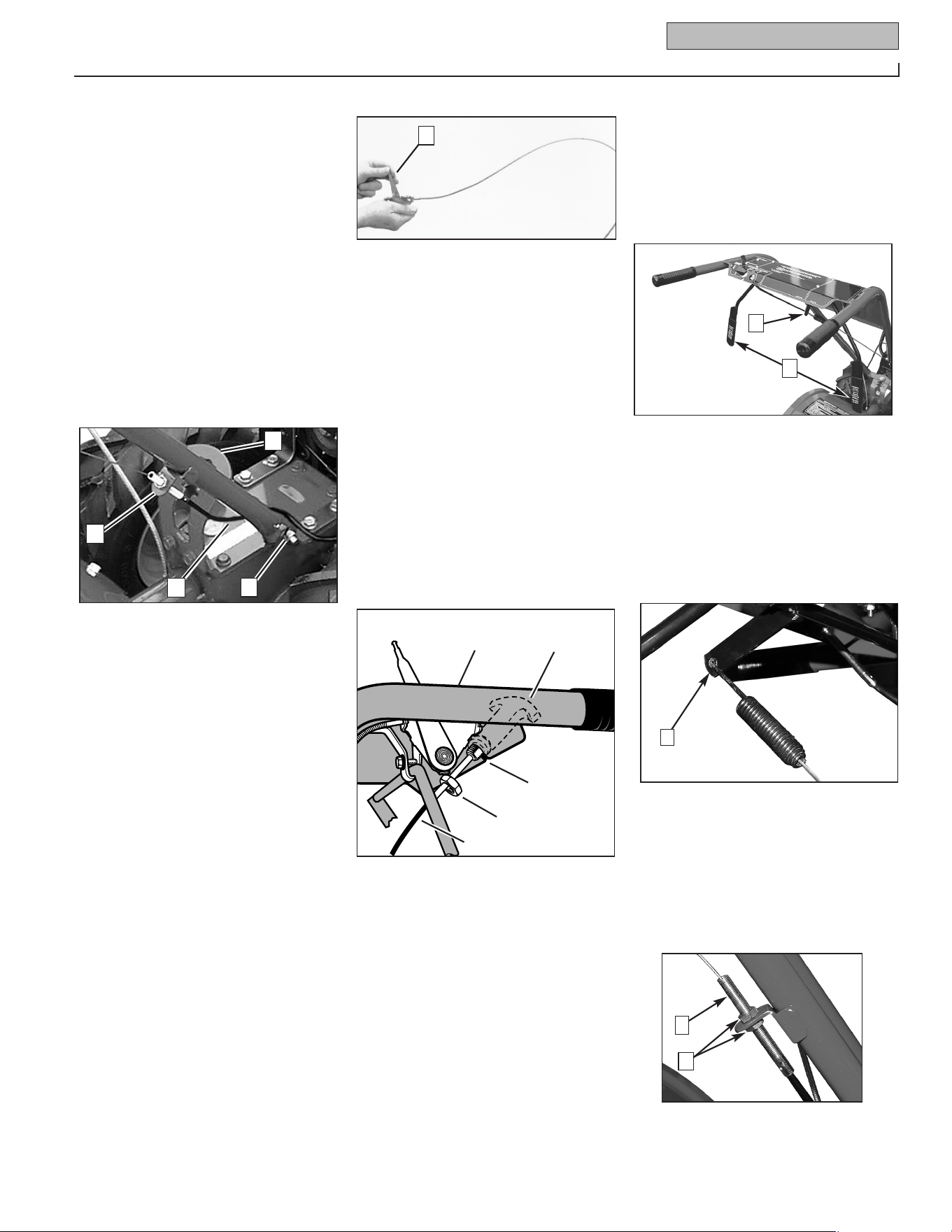
1. Carefully unwrap the reverse clutch
control cable (H, Figure 2-6) from its ship-
ping position and route it up along the
inside edge of the left side handlebar. A
knob and large hex nut (I) is installed on
the cable.
2. Insert the cable into the slot in the
control panel and fit the threaded assem-
bly into the hole in the slot (see Figure 2-
6). Be sure that the flat side of the
threaded assembly is aligned with the flat
side of the hole. Slide the hex nut (I) up
the cable and tighten it securely.
3. Test the function of the reverse clutch
control cable by pulling the knob out and
releasing it. The knob should return to its
neutral position against the tapered
bushing. If it doesn’t, contact your local
dealer or the factory for technical
assistance.
STEP 4: ATTACH FORWARD
CLUTCH CONTROL CABLE
1. Remove any fasteners (rubber bands,
tape, etc.) that may secure the Forward
Clutch Control levers (J, Figure 2-7) to the
handlebar.
2. The forward clutch control cable (with
attached spring) is hanging loosely near
the right-side wheel. Being careful not to
kink or stretch the cable, insert the z-con-
nector (L, Figure 2-8 – end of the spring)
into the hole at the end of the forward
clutch control linkage (K, Figure 2-7).
3. Attach the cable adjuster (A, Figure
2-9) to the bracket on the right-side han-
dlebar. Use two 1/2" wrenches to loosen
the two jam nuts (B) just enough to slide
the cable adjuster onto the bracket. Then
hand tighten the jam nuts.
Figure 2-6: Attach reverse clutch control
assembly to slotted hole in handlebar panel.
Figure 2-4: Attach handlebars.
Figure 2-5: Carefully unwrap Wheel Gear
Lever and move lever to DISENGAGE.
C
N
P
O
➥
I
H
Left Side
Handlebar
Reverse Clutch
Control Knob
Slot in
Control
Panel
Figure 2-7: Forward Clutch Control levers
(J). Forward clutch control linkage (K).
K
J
G
Figure 2-8
L
Figure 2-9
B
A
8 Section 2: Assembly
4. Check for correct spring/cable tension
as instructed in Section 5, Checking and
Adjusting Forward Clutch Belt Tension
.
5. When tension is correct, tighten the
two jam nuts (B) securely.
STEP 5: CHECK TRANSMISSION
GEAR OIL LEVEL
The transmission was filled with gear oil at
the factory. However, be sure to check the
oil level at this time to make certain it is
correct.
IMPORTANT: Do not operate the tiller if
the gear oil level is low. Doing so will
result in severe damage to the transmis-
sion components.
1. With the tiller on level ground, pull the
Depth Regulator Lever (R, Figure 2-13)
back and then slide it to the second notch
from the top. NOTE: If the lever does not
move, lift the tine hood flap and look for a
plastic tie securing the lever in place. Cut
and remove the tie.
2. Remove the oil level check plug (M,
Figure 2-10) on the left-side of the trans-
mission. (Due to dried paint on the plug
threads, it may require some force to
remove the plug the first time.) The gear
oil level is correct if oil starts to flow out of
the hole as the plug is removed. If so,
securely reinstall the plug.
3. If oil does not flow from the check
hole, add oil as follows:
NOTE: Do not use automatic transmission
fluid or motor oil in the transmission.
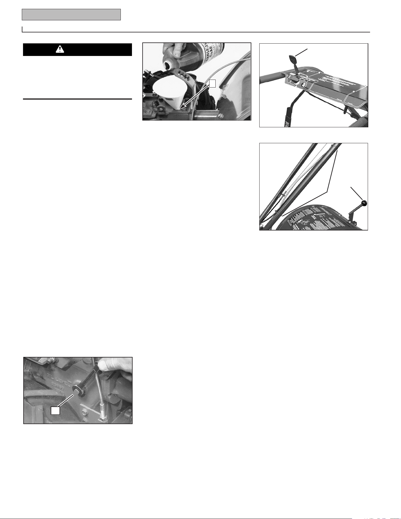
(a) Clean area around the fill hole (N,
Figure 2-11) and unscrew gear oil fill plug.
(b) If adding only a few ounces of gear oil,
use API rated GL-4 or GL-5 gear oil having
a viscosity of SAE 140, SAE 85W-140 or
SAE 80W-90. If refilling an empty trans-
mission, use only GL-4 gear oil having a
viscosity of SAE 85W-140 or SAE 140.
(c) Using a clean funnel, slowly add gear
oil until it flows from the gear oil level
check hole (N, Figure 2-11).
(d) Reinstall and tighten securely the gear
oil fill plug (M, Figure 2-10).
STEP 6: ATTACH WHEEL GEAR LEVER
1. Insert the Wheel Gear Lever (P, Figure
2-12) up through the slot in the control
panel that is labeled “WHEEL GEAR.”
2. Insert two #10-32 x 1/2" round head
screws down through the “+” marks on
the control panel decal and securely attach
the wheel gear mounting bracket using
two #10 lockwashers and #10-32 nuts.
3. Use a small board to tap the Wheel
Gear Lever knob securely onto the lever.
4. Secure the wheel gear cable and the
reverse clutch control cable to the left-side
handlebar with two plastic ties (S, Figure
2-13) located about two feet apart. Snip
off any excess tie length with
scissors.
STEP 7: CHECK AIR
PRESSURE IN TIRES
Use a tire pressure gauge to check the air
pressure in both tires. Deflate or inflate
both tires equally to between 15 PSI and
20 PSI). Be sure that both tires are
inflated equally or the unit will pull to one
side.
STEP 8: CHECK HARDWARE
FOR TIGHTNESS
Inspect the hardware on the unit and
tighten any loose screws, bolts and nuts.
Figure 2-10: Gear oil level check plug.
Figure 2-11: Adding gear oil.
Figure 2-13: Attach wheel gear cable and
reverse clutch cable with cable ties (S).
Figure 2-12: Attach Wheel Gear Lever.
S
R
P
N
M
Incorrect cable adjustment could cause
the wheels and tines to rotate unexpect-
edly. Follow adjustment procedures
carefully. Failure to do so could result
in personal injury or property damage.
CAUTION
Features and Controls
3
Section
9
TILLER FEATURES
AND CONTROLS
This section describes the location and
function of the controls on your tiller.
Refer to Section 4: Operation for detailed
operating instructions.
Practice using these controls, with the
engine shut off, until you understand the
operation of the controls and feel confi-
dent with each of them.
IMPORTANT: Refer to the separate engine
manufacturer’s Engine Owner’s Manual for
information about the controls on the
engine.
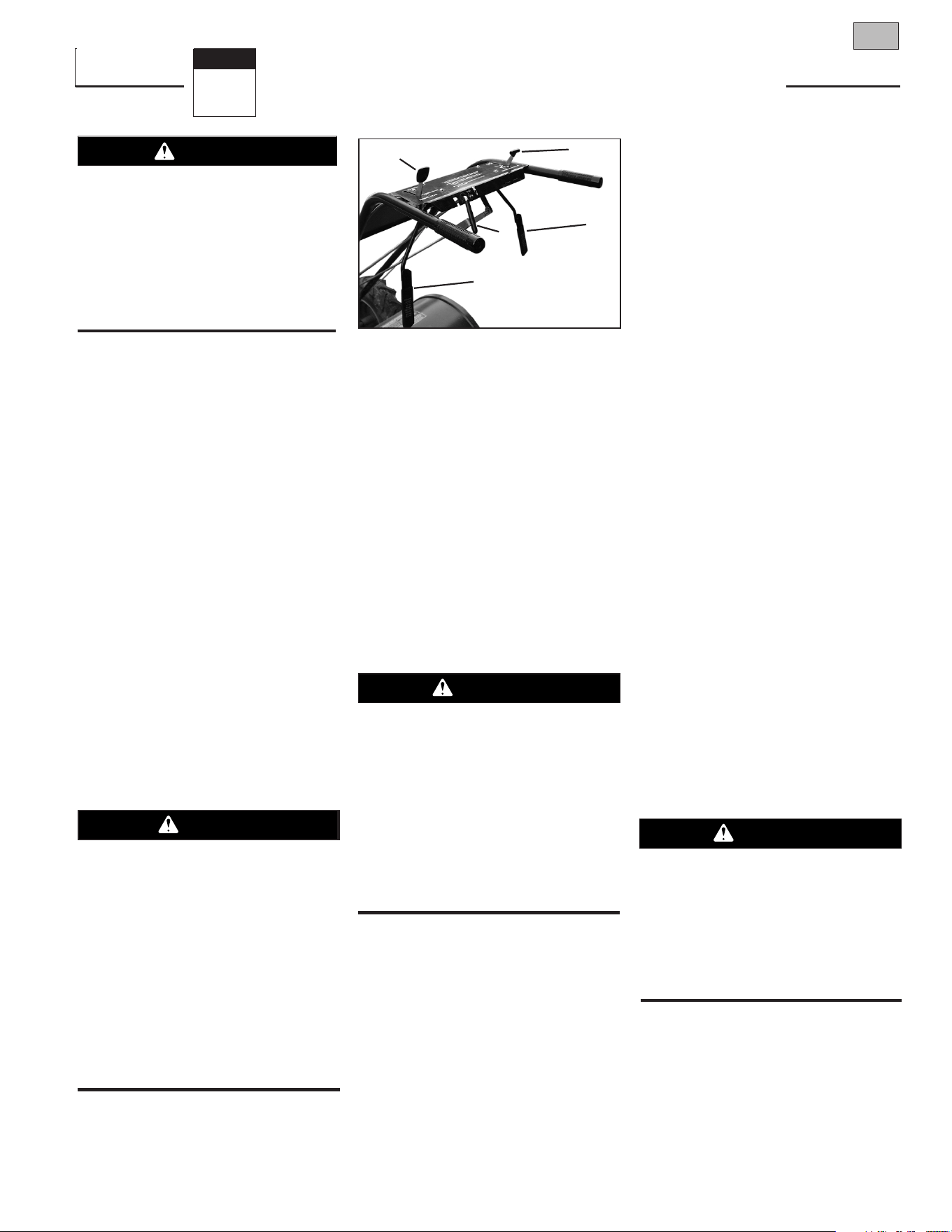
WHEEL GEAR LEVER
This lever (A, Figure 3-1) has two posi-
tions: ENGAGE and DISENGAGE.
In the ENGAGE position, the wheels will
start turning when either the Forward
Clutch or the Reverse Clutch is engaged.
NOTE: The tines will also start turning
when either clutch is engaged.
The DISENGAGE (freewheel) position
places the wheels in freewheeling mode to
allow the wheels to turn without starting
the engine. Use the DISENGAGE position
only when the engine is not running.
To shift to ENGAGE, gently (do not force)
move the lever forward while rolling the
tiller a few inches forward or backward.
(Moving the tiller helps align the transmis-
sion shift mechanism). The wheels will
not freewheel when the lever is properly
set in the ENGAGE position.
To shift to DISENGAGE, move the lever
rearward, without rolling the tiller. The
wheels roll freely when the lever is prop-
erly set in the DISENGAGE position.
FORWARD CLUTCH LEVERS
Two interconnected levers (B, Figure 3-1)
control engagement of the forward drive to
the wheels and power to the tines.
To Operate Forward Clutch:
1. Before engaging the Forward Clutch,
put the Wheel Gear Lever into the ENGAGE
position (see “WARNING” above).
2. Lift and hold one or both levers against
the handlebar grips to engage the wheels
and tines.
3. Release BOTH levers to disengage
wheels and tines. All forward motion will
stop (engine will continue to run).
IMPORTANT: The Forward Clutch Levers
are connected to a mechanical interlock
that automatically shifts a separate Wheel
Gear Lever (A, Figure 3-1) into ENGAGE
position when either Forward Clutch Lever
is pulled up against the handlebars. This
is a safety feature designed to prevent the
wheels from being in DISENGAGE (free-
wheel) position when the tines are
rotating.
Before starting the engine, test the func-
tion of the mechanical interlock as follows:
1. Put Wheel Gear Lever into DISENGAGE
position and roll tiller back and forth a few
inches. Wheels should roll freely.
2. Without rolling the tiller, squeeze either
Forward Clutch Lever against the handle-
bar grips. As the levers move upward, the
mechanical interlock automatically moves
the Wheel Gear Lever forward into the
ENGAGE position (roll tiller back and forth
a few inches). If it does, the wheels will
not roll freely when you push and pull on
the handlebars.
3. The mechanical interlock works prop-
erly if it functions as described in Step 2.
If the mechanical interlock does not func-
tion properly, do not operate the tiller until
it has been corrected (see your authorized
dealer or contact the factory).
REVERSE CLUTCH CONTROL
This control (C, Figure 3-1) engages the
reverse drive to the wheels and power to
the tines. It is used for moving the tiller
short distances in a reverse direction.
To Operate Reverse Clutch:
1.
Before engaging the Reverse Clutch,
put the Wheel Gear Lever into ENGAGE.
(see “WARNING” at left).
2. Release the Forward Clutch Levers.
3. To move the tiller in reverse, first stop
all forward motion. Lift up the handlebars
until the tines clear the ground and pull
the Reverse Clutch lever out.
Figure 3-1: Control panel.
B
B
C
D
Before operating your machine, care-
fully read and understand all safety,
controls and operating instructions in
this Manual, the separate Engine
Owner’s Manual, and on the decals on
the machine.
Failure to follow these instructions can
result in serious personal injury.
WARNING
Never place the Wheel Gear Lever in
DISENGAGE (Freewheel) when the
engine is running.
Having the Wheel Gear Lever in
DISENGAGE and then engaging the
tines/wheels with either the Forward
Clutch or the Reverse Clutch could allow
the tines to propel the tiller rapidly
backward.
Failure to follow this instruction could
result in personal injury or property
damage.
DANGER
Never engage wheels and tines with
Forward Clutch or Reverse Clutch unless
Wheel Gear Lever is in ENGAGE.
Engaging the Forward Clutch or Reverse
Clutch when wheels are not engaged
could allow the tines to rapidly propel
tiller backward.
Failure to follow this warning could
result in personal injury or property
damage.
WARNING
A
• Use extreme caution when reversing or
pulling the machine towards you. Look
behind to avoid obstacles.
• Never attempt to till in reverse.
Failure to follow this warning could
result in personal injury or property
damage.
WARNING
10 Section 3: Features and Controls
The wheels will rotate in a reverse direc-
tion as long as the lever is held in
REVERSE. To stop the wheels and tines,
release the lever and it will return to
NEUTRAL.
Never attempt to till while
moving in reverse direction.
DEPTH REGULATOR LEVER
This lever (E, Figure 3-2) controls the
tilling depth of the tines. Pull the lever
straight back and slide it up or down to
engage the notched height settings.
The highest notch (lever all the way down)
raises the tines approximately 1-1/2
inches off the ground. This “travel” posi-
tion allows the tiller to be moved without
the tines digging into the ground.
Moving the lever up increases the tilling
depth. The lowest notch allows a tilling
depth of approximately six to eight inches,
depending on soil conditions.
For best results, always begin tilling at a
very shallow depth setting and gradually
increase tilling depth.
HANDLEBAR HEIGHT ADJUSTMENT
Handlebar height is adjustable to four dif-
ferent settings. When setting the height,
keep in mind that the handlebars will be
lower when the tines are engaged in the
soil.
To Adjust Handlebar Height:
1. Stop engine, wait for all parts to stop
moving and then disconnect spark plug
wire.
2. Loosen the two screws at lower ends
of handlebar.
3. Loosen height adjustment screw (F,
Figure 3-3) and pull keyed washer (G) free
from slots in curved height adjustment
bracket.
4. Move handlebars to a new slot setting
and insert the raised key on the keyed
washer into the slot. Tighten the height
adjustment screw securely.
5. Retighten the two screws at ends of
handlebar.
ENGINE CONTROLS
IMPORTANT: The engine is equipped with
either a choke control or a primer bulb.
Refer to the Engine Owner’s Manual
(included in tiller literature package) to
identify which device is on your engine.
RECOIL STARTER
The recoil starter (H, Figure 3-4) is used to
“pull-start” the engine. See Engine Start-
ing and Stopping in Section 4 for detailed
engine starting instructions.
ENGINE THROTTLE LEVER
The throttle lever (D, Figure 3-1) is used to
adjust engine speed as well as stop the
engine. Use the START position when
starting the engine. Pull the lever all way
back to the STOP position to shut the
engine off.
• Place Depth Regulator Lever in
“travel” position before starting
engine. This position prevents the
tines from touching the ground until
you are ready to begin tilling.
• Do not attempt to till too deeply too
quickly. Gradually work down to deeper
tilling depths.
Failure to follow this warning could
result in personal injury or property
damage.
WARNING
Whenever the handlebar height is
changed, the Forward Clutch shift mech-
anism must be readjusted.
Before adjusting or checking the Forward
Clutch mechanism, shut engine off, dis-
connect spark plug wire and prevent it
from touching spark plug.
Failure to follow this warning could
cause the Forward Clutch mechanism to
operate improperly which could result in
personal injury or property damage.
WARNING
Figure 3-2: Depth Regulator Lever.
E
Figure 3-4: Recoil starter handle.
H
Figure 3-3: Handlebar height adjustment.
G
F
Operation
4
Section
11
INTRODUCTION
Read this Section of the manual thor-
oughly before you start the engine. Then,
take time to familiarize yourself with the
basic operation of the tiller before using it.
Find an open, level area and practice using
the tiller controls without engaging the
tines in the soil (put tines in “travel”
setting). Only after you’ve become com-
pletely familiar with the tiller should you
begin using it in the garden.
BREAK-IN OPERATION
Perform the following maintenance during
the first hours of new operation (see
Section 5: Maintenance and the mainte-
nance section of the Engine Owner’s
Manual).
1. Change motor oil after first 2 hours of
new engine operation.
2. Check for loose or missing hardware
on unit. Tighten or replace as needed.
3. Check tension on forward drive belt
after first 2 hours of operation.
4. Check transmission gear oil level after
first 2 hours of operation.
STARTING AND STOPPING ENGINE
The following steps describe how to start
and stop the engine. Do not engage the
tines or wheels until you have read all of
the operating instructions in this Section.
Also review the safety rules in Section 1:
Safety and the tiller and engine controls
information in Section 3: Features and
Controls.
Pre-Start Checklist
Do the following before starting the
engine.
1. Check unit for loose or missing hard-
ware. Service as required.
2. Check motor oil level. See Engine
Owner’s Manual.
3. Check that all safety guards and covers
are in place.
4. Check air cleaner and engine cooling
system. See Engine Owner’s Manual.
5. Select a forward belt speed range (see
Changing Belt Speed Ranges in this
Section).
6. Fill the fuel tank with gasoline accord-
ing to the directions in the separate Engine
Owner’s Manual. Follow all instructions
and safety rules carefully.
7. Attach spark plug wire to spark plug.
Starting the Engine
1.
Complete the Pre-Start Checklist.
2. Put the Wheel Gear Lever (Figure 4-1)
into the ENGAGE position.
3. Put the Depth Regulator Lever into the
“travel” position (lever all the way down)
so that the tines are clear of the ground.
4. Release all controls on the tiller.
5. If the engine is equipped with a fuel
shutoff valve, turn the valve to the open
position, as instructed in the separate
Engine Owner’s Manual.
6. Move the Engine Throttle Lever into the
START position.
7. Choke or prime the engine as instructed
in the separate Engine Owner’s Manual.
To help prevent serious personal injury
or damage to equipment:
• Before starting engine, put Wheel Gear
Lever into ENGAGE position.
• Before starting engine, put Forward Clutch
Levers and Reverse Clutch Control into
neutral (disengaged) positions by releas-
ing controls.
• Never run engine indoors or in an
enclosed, poorly ventilated area. Engine
exhaust contains carbon monoxide, an
odorless and deadly gas.
• Avoid engine muffler and nearby areas.
Temperatures in these areas may exceed
150
o
F.
CAUTION
Keep away from rotating tines. Rotating
tines will cause injury.
WARNING
Before operating your machine, carefully
read and understand all safety (Section
1), controls (Section 3) and operating
instructions (Section 4) in this Manual,
in the separate Engine Owner’s Manual,
and on the decals on the machine.
Failure to follow these instructions can
result in serious personal injury.
WARNING
GASOLINE IS HIGHLY FLAMMABLE AND
ITS VAPORS ARE EXPLOSIVE.
Follow gasoline safety rules in this manual
(see Section 1) and in the separate Engine
Owner’s Manual.
Failure to follow gasoline safety instruc-
tions can result in serious personal
injury and property damage.
DANGER
Figure 4-1
Forward Clutch Lever
Forward Clutch Lever
Reverse Clutch Control
Depth Regulator Lever
Throttle Lever
Recoil
Starter
Wheel Gear Lever
12 Section 4: Operation
8. Check behind you to avoid contacting
any obstacles when pulling the starter
rope. Place one hand on the fuel tank to
stabilize the unit and use the recoil starter
to start the engine as instructed in the
Engine Owner’s Manual. When the engine
starts, gradually move the choke lever (on
engines so equipped) to the NO CHOKE,
CHOKE OFF or RUN position, whichever
applies.
9. Use the FAST throttle speed setting
when tilling.
Stopping the Engine
1. To stop the wheels and tines, release
the Forward Clutch levers or the Reverse
Clutch Control (whichever control is in
use).
2. To stop the engine, move the Engine
Throttle Lever into the STOP position.
OPERATING TILLER
The following pages provide guidelines to
using your tiller effectively and safely in
various gardening applications. Be sure to
read Tilling Tips & Techniques in this
Section before you actually put the tines
into the soil.
1. Follow the Pre-Start Checklist on the
previous page. Be sure that the Wheel
Gear Lever is in the ENGAGE position.
2. Move the Depth Regulator Lever into
the “travel” position (lever all the way
down) so that the tines clear the ground.
Use this position when practicing with or
transporting the tiller. When you are ready
to begin tilling, move the Depth Regulator
Lever into the desired depth setting (see
Tilling Tips & Techniques).
3. Start the engine and allow it to warm
up. When warm, move the throttle control
into the FAST speed setting.
4. For forward motion of the wheels and
power to the tines:
(a) Pull up and hold the Forward Clutch
levers against the handlebars. To
stop the wheels and tines, release
both levers.
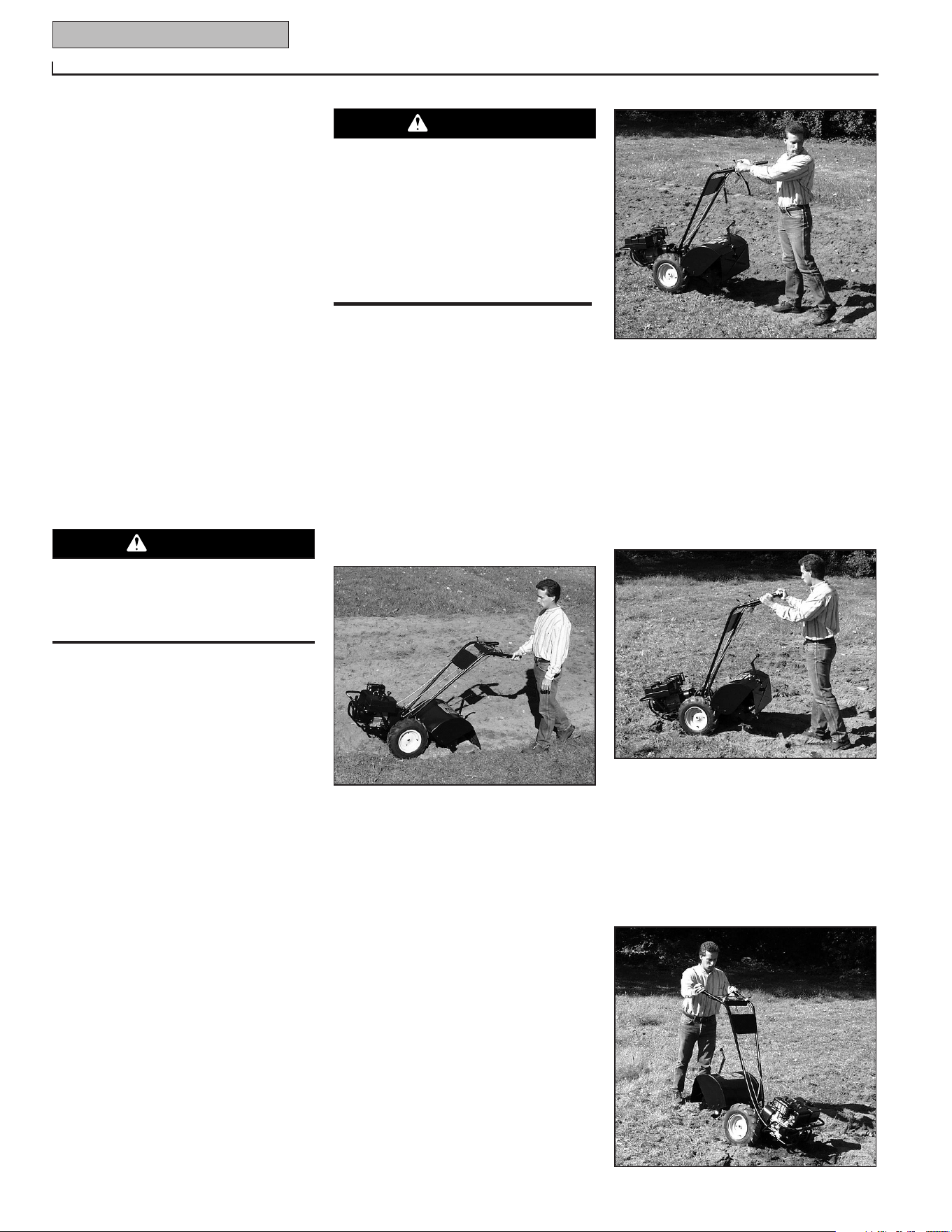
(b) As the tiller moves forward, relax and
let the wheels pull the unit along
while the tines dig. Walk behind and
a little to one side of the tiller. Use a
light but secure grip with one hand
on the handlebars, but keep your
arm loose. See Figure 4-2. Let the
tiller move ahead at its own pace.
Do not push down on the handlebars
to try and force the tiller to dig
deeper – this takes weight off the
wheels, reduces traction, and causes
the tines to try and propel the tiller.
5. For reverse motion of the wheels and
tines:
(a) Look behind and exercise caution
when operating in reverse.
Do not
till while in reverse.
(b) Stop all forward motion before
reversing. Lift the handlebars with
one hand until the tines are off the
ground and then pull the Reverse
Clutch control out (see Figure 4-3).
To stop reverse motion, let go of the
Reverse Clutch Control.
6. To turn the tiller around:
(a) Practice turning in a level, open area.
Be very careful to keep your feet and
legs away from the tines.
(b) To start a turn, reduce the engine
speed and then lift the handlebars
until the engine and tines are bal-
anced over the wheels (Figure 4-4).
(c) With the tiller balanced, push side-
ways on the handlebar to move the
tiller in the direction of the turn
(Figure 4-5). After completing the
turn, slowly lower the tines into the
soil and increase the engine speed.
Figure 4-2: Use one hand to guide tiller
when moving forward.
Figure 4-3: Raise tines off ground and look
behind when moving in reverse.
Figure 4-4: Find balance point before
turning.
Do not push down on the handlebars to
try to make the tiller till more deeply.
This prevents the wheels from holding
the tiller back and can allow the tines
to rapidly propel the tiller backward
toward the operator, which could result
in loss of control, property damage, or
personal injury.
WARNING
Before tilling, contact your telephone or
utilities company and inquire if
underground equipment or lines are on
your property.
WARNING
Figure 4-5
Section 4: Operation 13
Stopping the Tiller and Engine
1. To stop the wheels and tines, release
the Forward Clutch levers or the Reverse
Clutch Control (whichever is engaged).
2. To stop the engine, move the Engine
Throttle Lever to STOP.
3. If the engine is equipped with a fuel
shutoff valve, close the valve as instructed
in the Engine Owner’s Manual.
CHANGING BELT RANGE SPEEDS
The tiller has two forward belt range
speeds for the wheels and tines: Low and
High. The two ranges are obtained by
moving the forward drive belt between two
sets of grooves on the forward drive pulley
and the transmission drive pulley.
NOTE: The High speed belt range is rec-
ommended for all tilling purposes. The
Low speed belt range will operate the tines
and wheels at a slower forward speed,
which may be suitable in some conditions
(such as tilling in very hard ground).
To Change from Low to High Speed:
1. Stop the engine, allow it to cool, and
disconnect the spark plug wire.
2. Move the Wheel Gear Lever into the
DISENGAGE position.
3. Remove the two nuts from the plastic
belt cover on top of the transmission and
remove the belt cover.
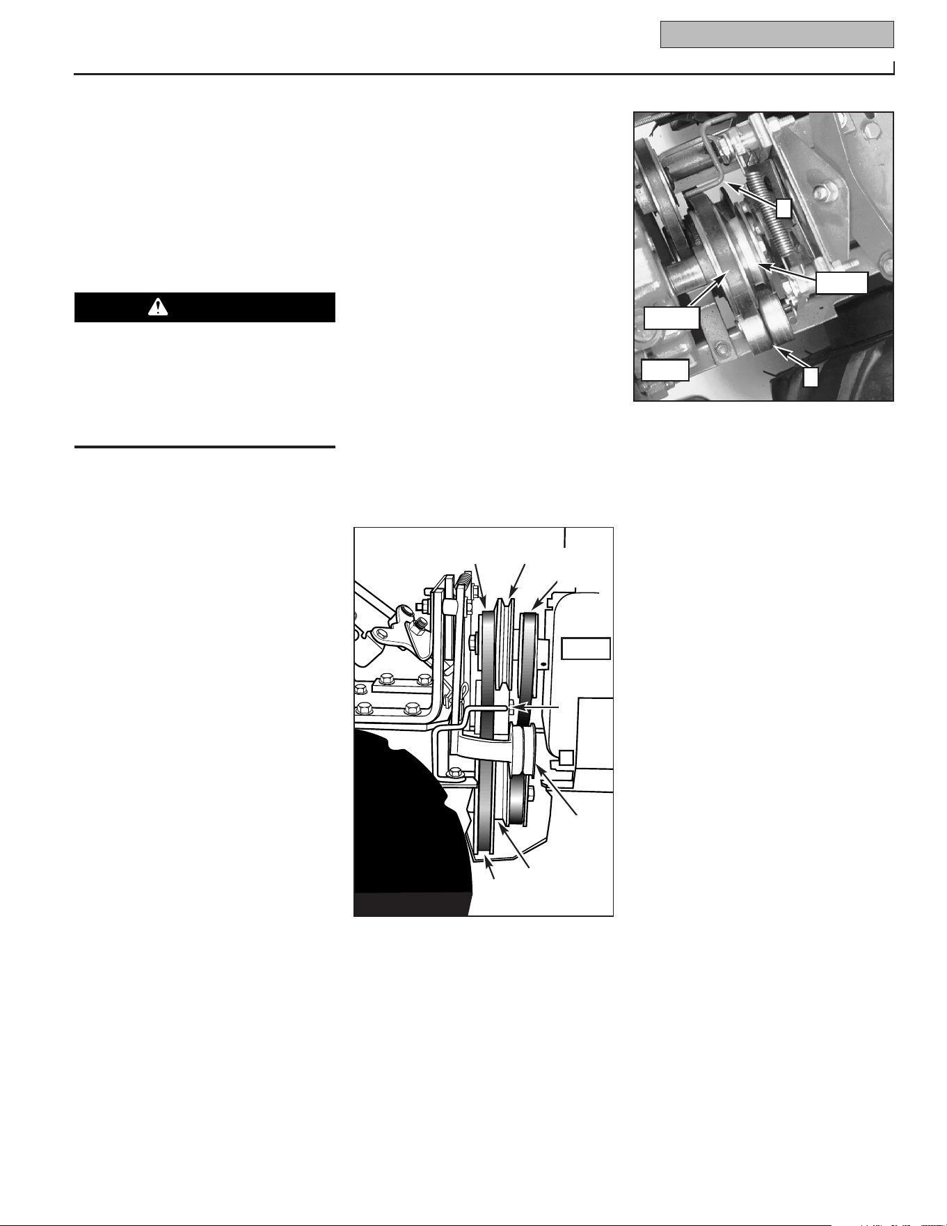
4. From beneath the tiller, move the
forward drive belt out of the transmission
low speed groove (B, Figure 4-10) and
into the high speed groove (D).
5. Pull upward on the belt to remove any
slack and slip the belt out of the engine
drive pulley low speed groove (A, Figure
4-10) and into the high speed groove (C).
NOTE: If the belt is difficult to move, pull
on the engine start rope while pushing the
belt with your finger (engine drive pulley
will turn as start rope is pulled).
6. Check that the belt is within the forward
belt guide (E, Figures 4-10 and 4-11) on
the right-side of the unit and is within the
forward idler (F, Figure 4-11) on the left-
side. Be sure that the belt is situated in
the center grooves (C and D, Figure 4-10)
of the engine (upper) and transmission
(lower) pulleys.
7. Reinstall the plastic belt cover and
secure it with the two nuts.
8. Put Wheel Gear Lever in ENGAGE and
reconnect spark plug wire before attempt-
ing to start the engine.
To Change from High to Low Speed:
1. Stop the engine, allow it to cool, and
disconnect the spark plug wire.
2. Put Wheel Gear Lever in DISENGAGE.
3. Remove the two nuts from the plastic
belt cover on top of the transmission and
remove the belt cover.
4. From beneath the tiller, move the
forward drive belt out of the transmission
pulley high speed groove (D, Figure 4-10)
and into the low speed groove (B).
5. Pull upward on the belt to remove any
slack and slip the belt out of the engine
drive pulley high speed groove (C, Figure
4-10) and into the low speed groove (A).
NOTE: If the belt is difficult to move, pull
on the engine start rope while pushing the
belt with your finger (engine drive pulley
will turn as start rope is pulled).
6. Check that the belt is within the forward
belt guide (E, Figures 4-10 and 4-11) on
the right-side of the unit and is within the
forward idler (F, Figure 4-11) on the left-
side. Be sure that the belt is situated in
the rear grooves (A and B, Figure 4-10) of
the engine (upper) and transmission
(lower) pulleys.
7. Reinstall the plastic belt cover and
secure it with the two nuts.
8. Put the Wheel Gear Lever in ENGAGE
and reconnect the spark plug wire before
attempting to start the engine.
Before changing belt speeds, stop
engine, wait for all parts to stop moving,
let engine cool and disconnect spark
plug wire.
Failure to follow these instructions could
result in personal injury.
WARNING
Figure 4-11: Top view of forward drive pulley
system (engine is at left-side of view).
Figure 4-10: Right-side view of engine and
transmission pulleys (engine is at right-side
of view).
Reverse
Belt
Reverse
Idler
E
A
(Low)
B
(Low)
C
(High)
D
(High)
(Low)
(High)
F
E
Engine
Engine
14 Section 4: Operation
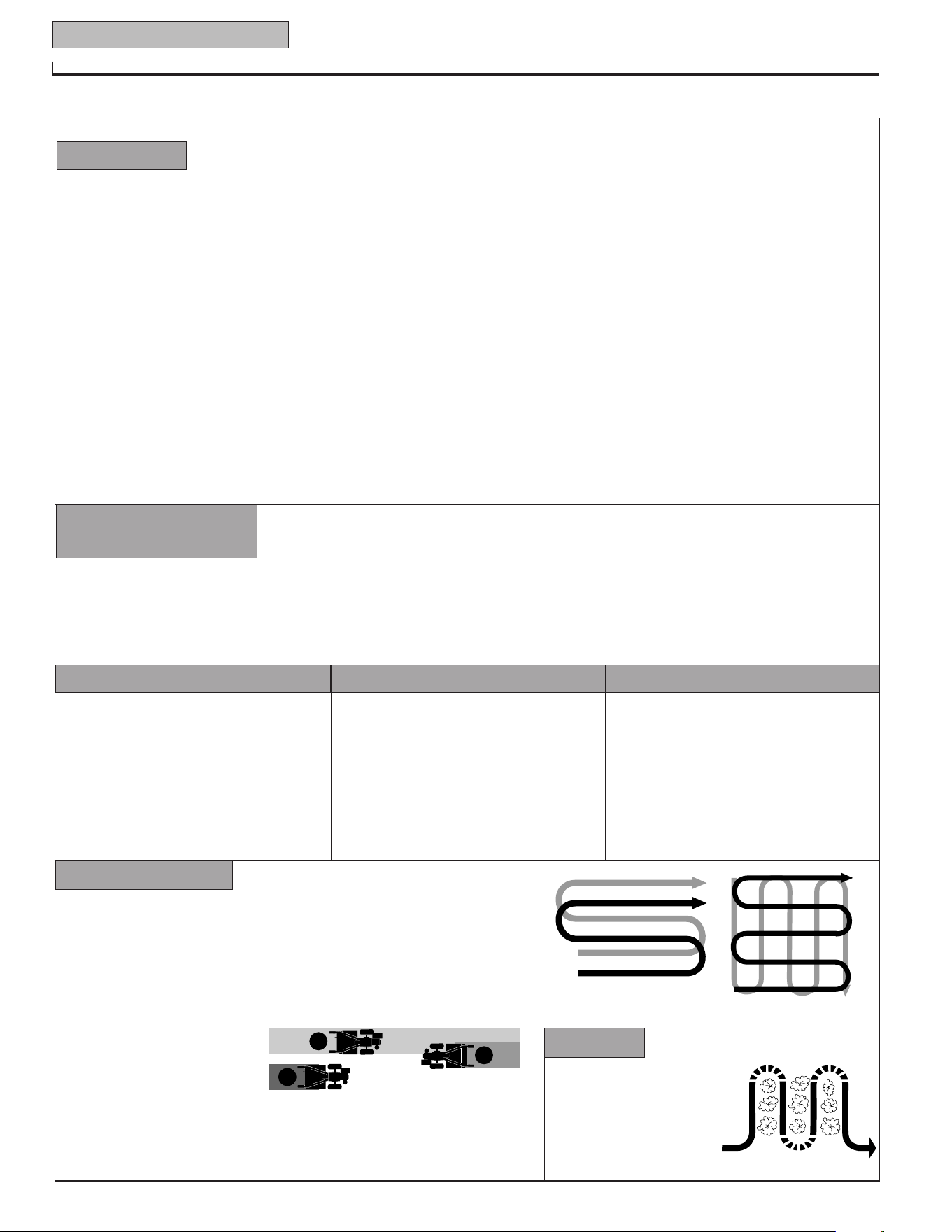
TILLING TIPS & TECHNIQUES
Preparing Seedbeds
Figure 4-6
Figure 4-7
• When preparing a seedbed, go over the same path twice in the first row, then
overlap one-half the tiller width on the rest of the passes (see Figure
4-6). When finished in one direction, make a second pass at a right angle as
shown in Figure 4-7. Overlap each pass for best results (in very hard ground,
it may take three or four passes to thoroughly pulverize the soil.)
• If the garden size will not
permit lengthwise and then
crosswise tilling, then overlap
the first passes by one-half a
tiller width, followed by succes-
sive passes at one-quarter
width (see Figure 4-8).
With planning, you can allow
enough room between rows to
cultivate (see Figure 4-9). Leave
room for the hood width,
plus enough extra room for
future plant growth.
Figure 4-9
1
2
3
• Avoid the temptation to push down on the handlebars in an
attempt to force the tiller to dig deeper. Doing so takes the weight
off the powered wheels, causing them to lose traction. Without the
wheels to hold the tiller back, the tines will attempt to propel the
tiller backward, towards the operator. (Sometimes, slight down-
ward pressure on the handlebars will help get through a particu-
larly tough section of sod or unbroken ground, but in most cases
this won’t be necessary.)
• Watering the garden area a few days prior to tilling will make
tilling easier, as will letting the newly worked soil set for a day or
two before making a final, deep tilling pass.
Tilling Depths
Figure 4-8
• This is a CRT (counter-rotating tine) tiller. As the wheels pull
forward, the tines rotate backward. This creates an “uppercut” tine
action which digs deeply, uprooting soil and weeds. Don’t over-
load the engine, but dig as deeply as possible on each pass. On
later passes, the wheels may tend to spin in the soft dirt. Help
them along by lifting up slightly on the handlebar (one hand, palm
up, works most easily).
• When cultivating (breaking up surface soil around plants to
destroy weeds, see Figure 4-9), adjust the tines to dig only
1" to 2" deep. Using shallow tilling depths helps prevent injury
to plants whose roots often grow close to the surface. If
needed, lift up on the handlebars slightly to prevent the tines
from digging too deeply. (Cultivating on a regular basis elimi-
nates weeds, and loosens and aerates the soil for better mois-
ture absorption and faster plant growth.)
Cultivating
Tilling wet soil often results in large, hard
clumps of soil that can interfere with plant-
ing. If time permits, wait a day or two after
heavy rains to allow the soil to dry before
tilling. Test soil by squeezing it into a ball.
If it compresses too easily, it is too wet to
till.
Avoid Tilling Soggy, Wet Soil
Whenever possible, walk on the untilled
side of the unit to avoid making footprints
in your freshly tilled or cultivated soil.
Footprints cause soil compaction that can
hamper root penetration and contribute to
soil erosion. They can also “plant”
unwanted weed seeds back into the
freshly tilled ground.
While tilling, relax and let the wheels pull
the tiller along while the tines do the
digging. Walk on the side that is not yet
finished (to avoid making footprints in the
freshly tilled soil) and lightly, but securely
grip the handlebar with just one hand.
Let the Tiller Do the Work Avoid Making Footprints
With experience, you will find the “just right” tilling depth and tilling speed combination that is best for
your garden.
Set the engine throttle lever at a speed to give the engine adequate power and yet allow it to operate at the slowest possible speed...at least
until you have achieved the maximum tilling depth you desire. Faster engine speeds may be desirable when making final passes through
the seedbed or when cultivating. Selection of the correct engine speed, in relation to the tilling depth, will ensure a sufficient power level to
do the job without causing the engine to labor.
Choosing Correct
Wheel and Tine Speeds

Section 4: Operation 15
LOADING AND UNLOADING TILLER
• Before loading or unloading, stop the
engine, wait for all parts to stop moving,
disconnect the spark plug wire and let
the engine and muffler cool.
• The tiller is too heavy (over 175 lbs.,
depending on model) and bulky to lift
safely by one person. Two or more
people should share the load.
• Use sturdy ramps and manually (engine
shut off) roll the tiller into and out of the
vehicle. Two or more people are needed
to do this.
• Ramps must be strong enough to
support the combined weight of the tiller
and any handlers. The ramps should
provide good traction to prevent slipping;
they should have side rails to guide the
tiller along the ramps; and they should
have a locking device to secure them to
the vehicle.
• The handlers should wear sturdy
footwear that will help to prevent
slipping.
• Position loading vehicle with ramp angle
as flat as possible (the less incline to the
ramp, the better). Turn vehicle’s engine
off and apply its parking brake.
• When going up the ramps, stand in the
normal operating position and push the
tiller ahead of you. Have a person at
each side to turn the wheels.
• When going down ramps, walk backward
with the tiller following you. Keep alert
for any obstacles behind you. Position a
person at each wheel to control the
speed of the tiller. Never go down ramps
tiller-first, as the tiller could tip forward.
• Place wooden blocks on the downhill
side of the wheels if you need to stop the
tiller from rolling down the ramp. Also,
use the blocks to temporarily keep the
tiller in place on the ramps (if necessary),
and to chock the wheels in place after the
tiller is in the vehicle.
• After loading the tiller, prevent it from
rolling by engaging the wheels (put
Wheel Gear Lever into ENGAGE). Chock
the wheels with blocks and securely tie
the tiller down.
Loading and unloading the tiller into a
vehicle is potentially hazardous and we
don’t recommend doing so unless abso-
lutely necessary, as this could result in
personal injury or property damage.
However, if you must load or unload the
tiller, follow the guidelines given next.
WARNING
Tilling On Slopes
The tines have a self-clearing action which eliminates most tangling of debris in the tines.
However, occasionally dry grass, stringy stalks or tough vines may become tangled.
Follow these procedures to help avoid tangling and to clean the tines, if necessary.
• To reduce tangling, set the depth regulator deep enough to get maximum “chopping”
action as the tines chop the material against the ground. Also, try to till under crop
residues or cover crops while they are green, moist and tender.
• While tilling, try swaying the handlebars from side to side (about 6" to 12"). This “fishtail-
ing” action often clears the tines of debris.
• If tangling occurs, lift the tines out of the soil and run the tiller in reverse (if unit is
equipped with powered reverse) for a few feet. This reversing action of the tines should
unwind most of the debris.
• It may be necessary to remove the debris by hand (a pocket knife will help you to cut
away the material). Stop the engine and disconnect the spark plug wire before clearing
the tines by hand.
Read the following recommendations before tilling on slopes:
If you must garden on a moderate slope, please follow two very
important guidelines:
1. Till only on moderate slopes, never on steep ground where
footing is difficult (review safety rules in Section 1:
Safety of this
manual).
2. Till up and down slopes rather than across slopes. Tilling verti-
cally on a slope allows maximum planting area and also leaves
room for cultivating.
IMPORTANT: When tilling on slopes, maintain correct motor oil
level (check every one-half hour of operation). The slope incline
causes the oil to slant away from its normal level which can starve
engine parts of lubrication. Keep the motor oil level at the full point
at all times!
Tilling Up and Down Slopes (Vertical Tilling)
• To minimize soil erosion, add enough organic matter to the soil for
good moisture-holding texture, and avoid leaving footprints or
wheel marks.
• When tilling vertically, try to make the first pass uphill (the tiller
digs more deeply going uphill than it does downhill). In soft soil
or weeds, you may have to lift the handlebars slightly while going
uphill. When going downhill, overlap the first pass by about one-
half the width of the tiller.
TILLING TIPS & TECHNIQUES (cont.)
Clearing the Tines
Before clearing the tines by hand, stop
the engine, allow all moving parts to
stop and disconnect the spark plug
wire. Remove the ignition key on elec-
tric start models. Failure to follow
this warning could result in personal
injury.
WARNING
Do not operate the tiller on a slope too steep for safe opera-
tion. Till slowly and be sure that you have good footing.
Never permit the tiller to freewheel down slopes. Failure to
follow this warning could result in personal injury.
WARNING
Maintenance
5
Section
16
TILLER LUBRICATION
Proper lubrication of the tiller is an essen-
tial part of your maintenance program.
After every 10 operating hours, oil or
grease the lubrication points shown in
Figures 5-1 and 5-2 and described below.
Use general purpose lubricating oil (#30
weight motor oil is suitable) and a general
purpose grease (metal lubricant is pre-
ferred, if available).
• Remove wheels and clean wheel shaft
(A, Figure 5-1). Apply a thin coating of
grease to shaft before reinstalling
wheels.
• Grease back, front and sides of depth
regulator lever (B, Figure 5-1).
• Remove tines and clean tine shafts (C,
Figure 5-1). Inspect for rust, rough
spots or burrs (especially around holes).
File or sand smooth and coat ends of
shaft with grease.
• Oil the threads on the handlebar height
adjustment handle (D, Figure 5-1).
• Oil the outer casings of the engine throt-
tle cable and the wheel gear cable (E,
Figure 5-1). Allow oil to soak in and
then wipe off any excess.
• Oil the various pivot points (F, Figure
5-2) on the shifting mechanism, the han-
dlebar, and the idler arms (do not allow
oil on the belts or pulleys).
CHECK TIRE AIR PRESSURE
Check the air pressure in both tires.
Deflate or inflate both tires evenly to
between 15 and 20 PSI (pounds per
square inch). Be sure that both tires have
equal air pressure or the unit will pull to
one side.
CHECK FOR OIL LEAKS
Before each use, check your tiller for signs
of an oil leak—usually a dirty, oily accu-
mulation either on the unit or on the floor
where it has been parked.
A little seepage around a cover or oil seal
is usually not a cause for alarm. However,
if the oil drips overnight, then immediate
attention is needed—ignoring a leak can
result in severe transmission damage.
If a cover leaks, try tightening any loose
screws or bolts. If the fasteners are tight,
a new gasket or oil seal may be required.
If the leak is from around a shaft and oil
seal, the oil seal probably needs to be
replaced. See your authorized dealer or
contact the factory for service or advice.
IMPORTANT: Never operate the tiller if the
transmission is low on oil. Check the oil
level after every 30 hours of operation and
whenever there is any oil leakage.
CHECK HARDWARE
Check the unit for loose or missing hard-
ware after every 10 operating hours.
Loose or missing hardware can lead to
equipment failure, poor performance, or
oil leaks.
Be sure to check the three end cap mount-
ing screws located at the rear of the trans-
mission (Figure 5-3). Lift the tine flap to
service those screws.
TRANSMISSION GEAR OIL SERVICE
Check the transmission gear oil level after
every 30 hours of operation or whenever
you notice any oil leak. Operating the tiller
when the transmission is low on oil can
result in severe damage.
A. To Check Transmission
Gear Oil Level:
1.
Check the gear oil level when the trans-
mission is cool. Gear oil expands in warm
operating temperatures and will result in
an incorrect oil level reading.
Before inspecting, cleaning or
servicing the machine, shut off engine,
wait for all moving parts to come to a
complete stop, disconnect spark plug
wire and move wire away from spark
plug. Remove ignition key on electric
start models.
Failure to follow these instructions can
result in serious personal injury or prop-
erty damage.
WARNING
MAINTENANCE SCHEDULE
PROCEDURE NOTES
Check motor oil level 2, 3
Clean engine 2, 7
Check drive belt tension 1, 4
Check nuts and bolts 1, 4
Change motor oil 1, 4, 6
Lubricate tiller 4
Service foam pre-cleaner air filter
(if so equipped)
7
Service paper air filter
(if so equipped)
7
Check gear oil level in transmission 1, 5
Check tines for wear 5
Check air pressure in tires 5
Service spark plug 7
NOTES
1 - After first 2 hours of break-in operation.
2 - Before each use.
3 - Every 5 operating hours.
4 - Every 10 operating hours.
5 - Every 30 operating hours.
6 - Change more frequently in dusty or dirty
conditions.
7 - See Engine Owner’s Manual for service
recommendations.
8 - Whichever time interval occurs first.
Figure 5-1
Figure 5-3
Figure 5-2
A
B
C
F
D
E
E
End
Cap
Section 5: Maintenance 17
Before inspecting, cleaning or servicing the machine, shut off engine, wait for all moving parts to come to
a complete stop, disconnect spark plug wire and move wire away from spark plug.
Failure to follow these instructions can result in serious personal injury or property damage.
WARNING
2. To check the gear oil level (and to add
oil, if necessary), refer to STEP 5: Check
Gear Oil Level in Transmission
in Section
2 of this manual.
B. To Drain and Refill the Transmission:
The transmission gear oil does not need to
be changed unless it has been contami-
nated with dirt, sand or metal particles.
1. Prop up the left side of the unit
securely. Remove the left-side wheel by
removing the wheel mounting hardware.
2. Unscrew the plastic gear oil fill plug
from the top of the transmission
(L, Figure 2-11).
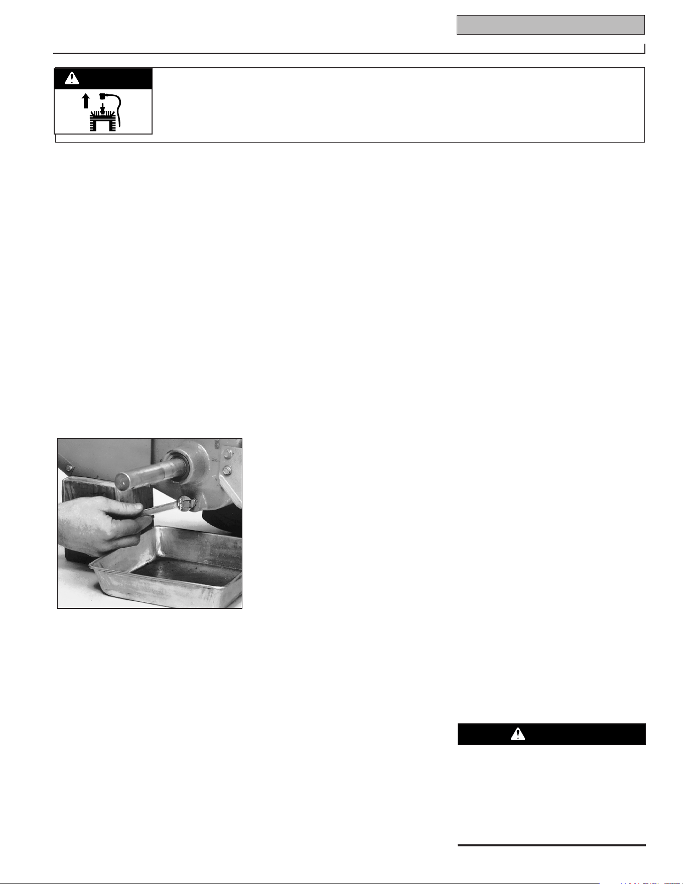
3. Place a clean pan below the transmis-
sion drain plug (Figure 5-4) and remove
the drain plug. The oil will start flowing
out of the drain hole (it may flow slowly,
especially in cold temperatures).
4. Remove the transmission gear oil level
check plug that is located a few inches
above the left-side wheel shaft (N, Figure
2-11).
5. When the oil stops flowing, tilt the
transmission forward to drain oil from the
rear of the transmission.
6. After draining the oil, clean the threads
of the drain plug, apply a non-hardening,
removable gasket sealant to the threads,
and securely reinstall the drain plug.
7. Use a clean funnel to slowly add SAE
140 or SAE 85W-140 weight gear oil (with
an API rating of GL-4 only) to the trans-
mission. The transmission holds approxi-
mately 3-1/4 pints (52-54 ounces). Tilt
the tiller slightly backwards to make sure
the gear oil reaches the rear (tine) end of
the transmission. Stop adding gear oil
when it begins to flow from the oil level
check hole on the side of the
transmission.
8. Securely reinstall the oil level check
plug.
9. Securely reinstall the gear oil fill plug
on top of the transmission.
10. Reinstall the wheel and remove the
prop.
ENGINE OIL SERVICE
Check the motor oil level before starting
the engine each day and after each 5
hours of continuous operation. Running
the engine when the oil level is low will
quickly ruin the engine.
It is recommended that you change the
motor oil after every 10 hours of operation
and even sooner when operating in
extremely dirty or dusty conditions.
A. To Check the Motor Oil Level:
1. Move the tiller to a level area and stop
the engine.
2. Level the engine by moving the Depth
Regulator Lever into the second notch
from the top.
3. Clean the area around the oil dipstick or
oil fill tube (whichever applies) to prevent
dirt from falling into the crankcase.
4. On engines with an oil fill tube, remove
the filler cap and add oil (if required) until
it reaches the top of the tube. Reinstall
the filler cap.
5. On engines with a dipstick, remove it,
wipe it clean, and reinstall it finger-tight.
Remove the dipstick again and check the
reading. Add oil (if required) to bring the
level to the FULL mark. Do not overfill.
B. To Change the Motor Oil:
Change the motor oil as instructed in the
separate Engine Owner’s Manual.
AIR CLEANER SERVICE
The engine air cleaner filters dirt and dust
out of the air before it enters the carbure-
tor. Operating the engine with a dirty,
clogged air filter can cause poor perfor-
mance and damage to the engine. Never
operate the engine without the air cleaner
installed. Inspect and service the air
cleaner more often if operating in very
dusty or dirty conditions.
Service the air cleaner as instructed in the
separate Engine Owner’s Manual.
SPARK PLUG SERVICE
Inspect and clean or replace the spark
plug after every 100 operating hours or
annually. Clean the plug and set the gap
as described in the separate Engine
Owner’s Manual.
In some areas, local law requires using
resistor spark plugs to suppress ignition
signals. If the engine was originally
equipped with a resistor spark plug, use
the same type for replacement.
SPARK ARRESTER SCREEN SERVICE
If the engine muffler is equipped with a
spark arrester screen, remove and clean it
according to the time intervals and
instructions in the separate Engine
Owner’s Manual.
ENGINE CLEANING
The engine must be kept clean to assure
smooth operation and to prevent damage
from overheating. Refer to the separate
Engine Owner’s Manual for specific repair
and cleaning instructions. All inspections
and services must be done with the engine
shut off and cool to the touch.
CARBURETOR/GOVERNOR
CONTROL ADJUSTMENTS
Figure 5-4: Remove drain plug to drain
transmission gear oil (also remove oil fill
plug and oil level check plug).
Operators shall not tamper with the
engine governor settings; the governor
controls the maximum safe operating
speed to protect the engine and all
moving parts from damage caused by
overspeed. Authorized service shall be
sought if a problem exists.
WARNING
18 Section 5: Maintenance
Before inspecting, cleaning or servicing the machine, shut off engine, wait for all moving parts to come to
a complete stop, disconnect spark plug wire and move wire away from spark plug.
Failure to follow these instructions can result in serious personal injury or property damage.
WARNING
The carburetor was adjusted at the factory
for best operating speed. Refer to the
separate Engine Owner’s Manual for any
adjustment information or see your autho-
rized engine service dealer.
The governor controls the maximum safe
operating speed and protects the engine
and all moving parts from damage caused
by overspeeding. Do not tamper with the
engine governor settings. Seek authorized
service if a problem exists.
THROTTLE CONTROL
ADJUSTMENT
If the engine does not respond to various
throttle lever settings, refer to the separate
Engine Owner’s Manual for service infor-
mation or contact your local authorized
engine service dealer.
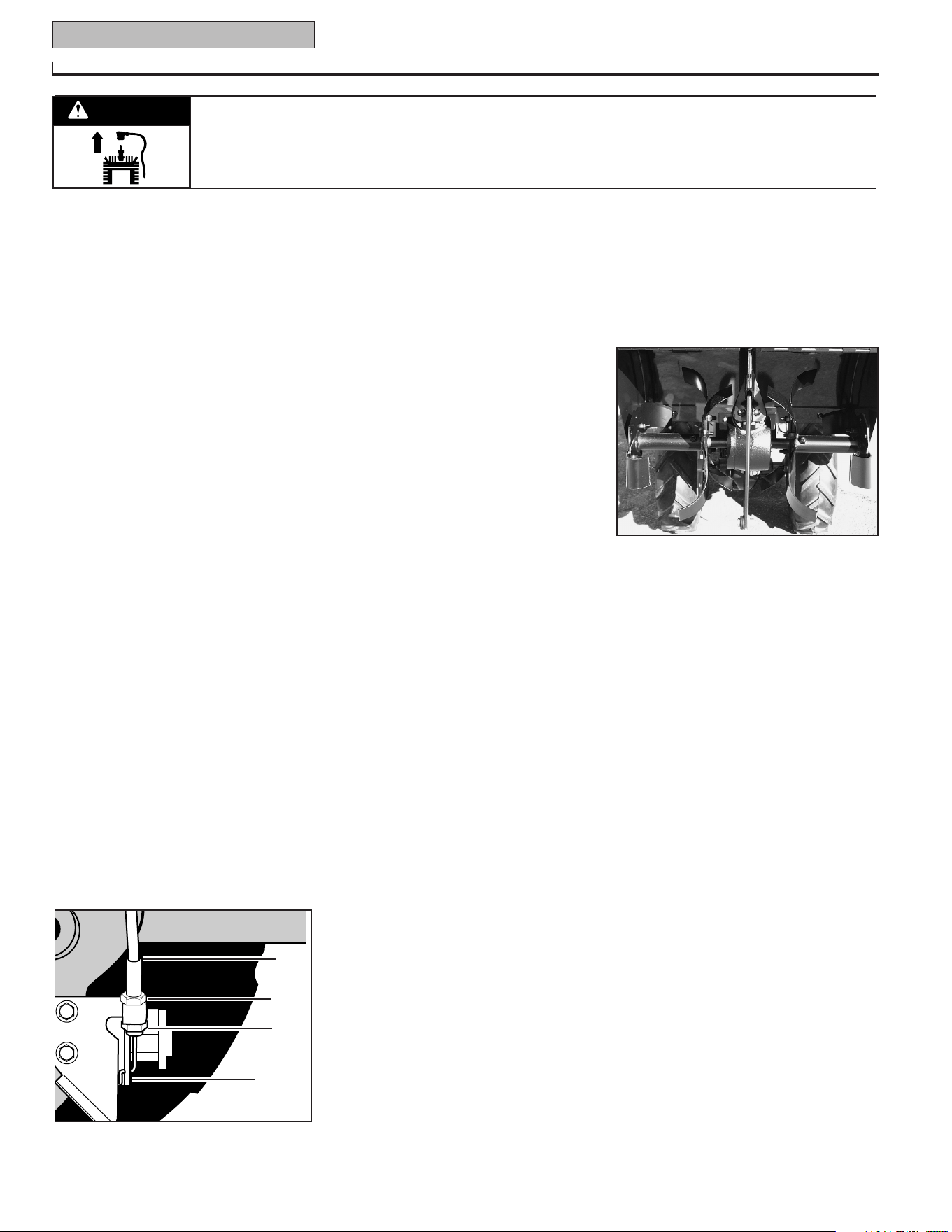
WHEEL GEAR CABLE
ADJUSTMENT
When the Wheel Gear Lever is in DISEN-
GAGE, the wheels will roll freely (free-
wheel). The wheels should not roll freely
when the lever is in ENGAGE. If the
wheels roll freely when the Wheel Gear
Lever is in ENGAGE, the wheel gear cable
needs to be adjusted as described below.
1. With the engine shut off and the spark
plug wire disconnected, put the Wheel
Gear Lever in ENGAGE.
2. Loosen the top adjustment nut
(A, Figure 5-5) on the wheel gear cable
bracket located on the left side rear of the
transmission.
3. Push wheel gear cable (B) down and
roll tiller slightly forward or backward until
eccentric lever (C) engages (locks)
wheels. Hold cable in that position and
tighten top (A) and bottom (D) adjustment
nuts.
4. Move Wheel Gear Lever to ENGAGE and
DISENGAGE several times to check adjust-
ment. The wheels should not roll when
the lever is in ENGAGE, but they should
roll when the lever is in DISENGAGE.
Readjust the cable as required.
OFF SEASON STORAGE
When the tiller won’t be used for extended
periods, prepare it for storage as follows:
1. Clean the tiller and engine.
2. Do routine tiller lubrication (see Tiller
Lubrication) and check for loose parts and
hardware (see
Check Hardware).
3. Protect the engine by performing the
engine storage instructions in the separate
Engine Owner’s Manual.
NOTE: Be sure to protect the fuel lines,
carburetor and fuel tank from gum
deposits by removing fuel or by treating
fuel with a fuel stabilizer (follow engine
manufacturer’s recommendations).
4. Store unit in a clean, dry area.
5. Never store the tiller with fuel in the fuel
tank in an enclosed area where gas fumes
could reach an open flame or spark, or
where ignition sources are present (space
heaters, hot water heaters, furnaces, etc.).
TINES
The tines will wear with use and should be
inspected at the beginning of each tilling
season and after every 30 operating
hours. Tines can be replaced individually
or as a complete set. Never inspect or
service the tines unless the engine is
stopped and the spark plug wire is
disconnected.
NOTE: The tiller hood must be removed to
take off either a single tine holder or indi-
vidual tines. The hood is secured to the
transmission housing with two rear bolts
and two front bolts.
Tine Inspection
With use, the tines (Figure 5-6) will
become shorter, narrower and pointed.
Badly worn tines will result in a loss of
tilling depth and reduced effectiveness
when chopping up and turning under
organic matter.
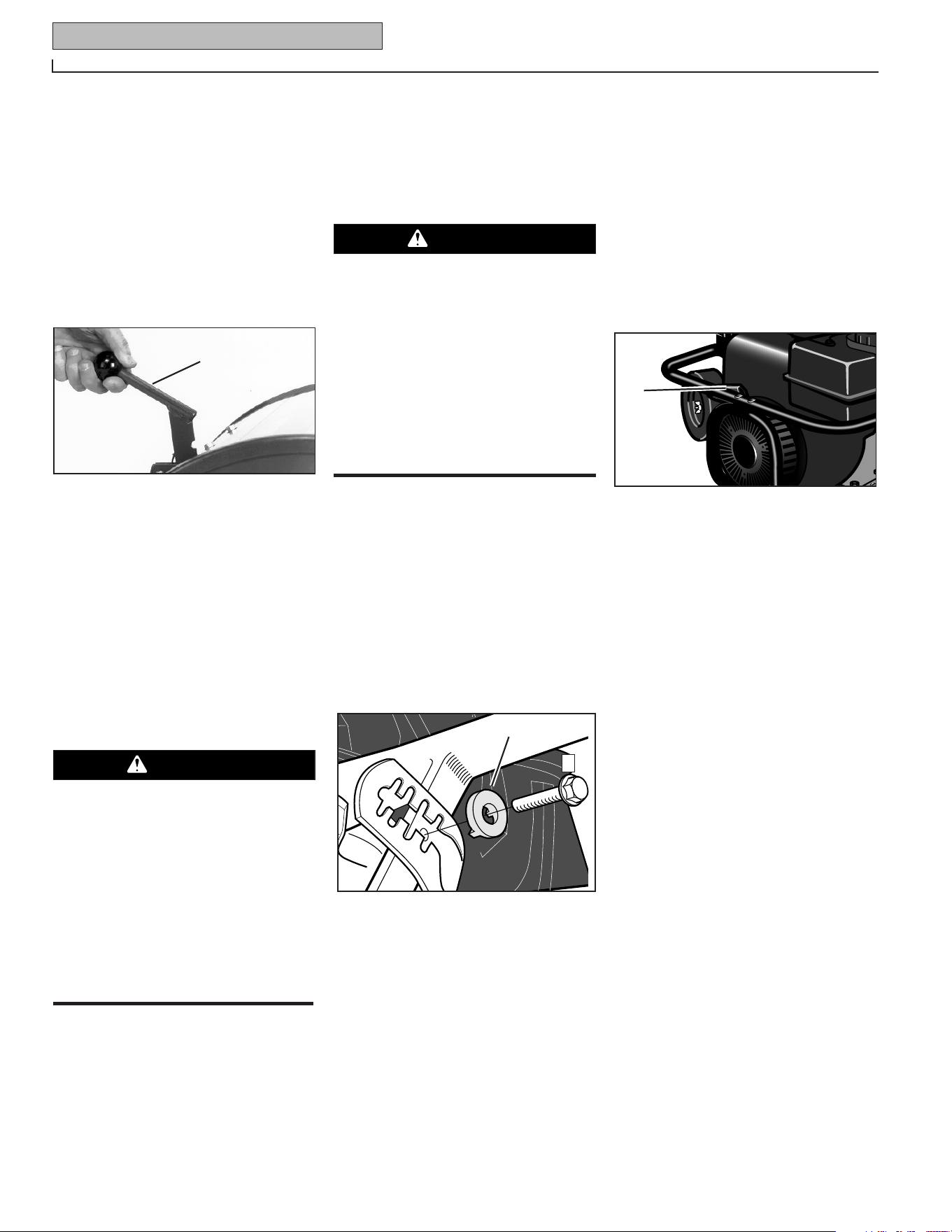
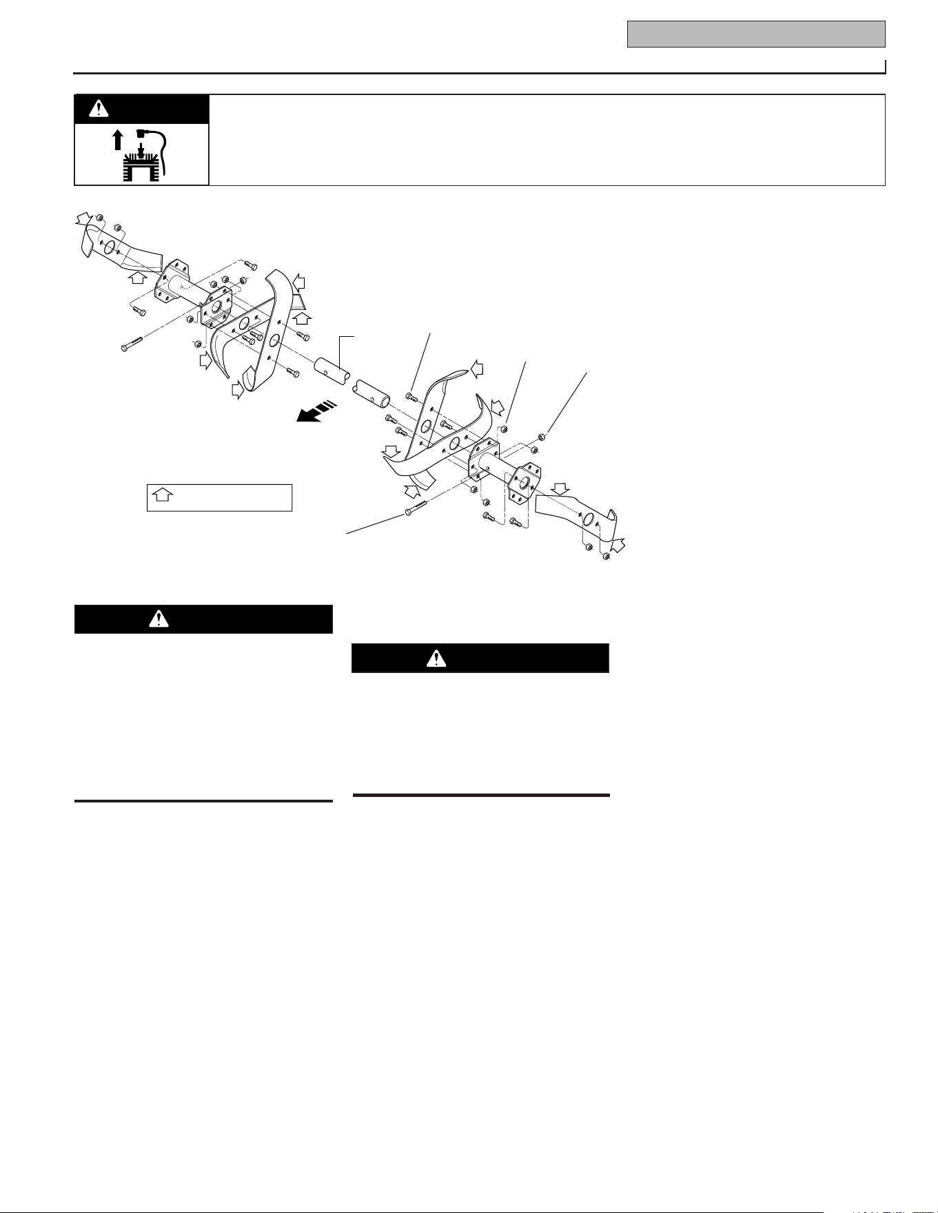
Removing and Installing
Tine Assemblies
1. Use a 9/16" socket, 6" extension, a
ratchet, and a 9/16" box wrench to loosen
the nut (A, Figure 5-7) and bolt (B) that
secure the tine holder to the tine shaft.
2. Use a rubber mallet to tap the tine
holder loose.
3. Slide the tine assembly off the tine
shaft.
4. Repeat Steps 1-through-3 above to
remove the other tine assembly.
5. Installing the tine assembly is simply
the reverse of its removal. Be sure the
cutting edges face so they will enter the
soil first when the tiller is moving
forward–
this means the cutting edges
face toward the operator position.
First be sure to remove any rust, uneven
spots or burrs from the tine shaft, using
fine sandpaper. Then grease the tine shaft
before reinstalling the tine assemblies.
Tighten the hardware very securely.
Removing and Installing
Individual Tines
1. Use two 9/16" box end wrenches to
remove the two bolts (C, Figure 5-7), and
nuts (D) that secure the tine to its tine
holder.
Figure 5-5: Wheel gear cable assembly.
B
A
C
D
Figure 5-6: Four tine gangs: two per side.
Section 5: Maintenance 19
Before inspecting, cleaning or servicing the machine, shut off engine, wait for all moving parts to come to
a complete stop, disconnect spark plug wire and move wire away from spark plug.
Failure to follow these instructions can result in serious personal injury or property damage.
WARNING
NOTE: If the nuts are rusted, apply pene-
trating oil to the bolt and nut. Let the oil
soak in for a few minutes before loosen-
ing the nut. Always loosen the nut rather
than the bolt.
2. When installing individual tines, install
them in the reverse order from which
they were removed. The two sets of
inboard tines are installed so one tine
faces toward the transmission housing
and the other tine faces away from it.
The single outboard tine on each side
faces toward the transmission housing.
Also be sure the cutting edges face so
they will enter the soil first when the tiller
is moving forward–
this means the
cutting edges face toward the operator
position.
CHECKING AND ADJUSTING
TENSION ON DRIVE BELTS
Maintaining correct tension on the drive
belts is important to good tilling perfor-
mance and long belt life. A loose belt will
slip on the engine and transmission
pulleys and cause the tines and wheels to
slow down – or stop completely – even
though the engine is running at full
speed. A loose belt will also result in pre-
mature wear to the belt.
While checking belt tension, also check
for cracks, cuts or frayed edges. A belt
that is in poor condition should be
replaced.
The tension on a new forward drive belt
should be checked after the first two (2)
hours of operation. Thereafter, check the
tension after every ten (10) hours of
operation.
The reverse drive belt, because it is used
more sparingly, will probably not require
an initial tension adjustment until a sig-
nificant number of operating hours has
passed.
To Check and Adjust Tension
on the Forward Drive Belt:
1.
Checking for correct belt tension is the
same as that described in item 5, Step 4:
Attach Forward Clutch Rod. Before
checking, shut off the engine, disconnect
the spark plug wire, and allow the engine
and muffler to cool down. If, after follow-
ing the adjustment procedures, you
cannot get the correct gap on the forward
clutch rod adjustment bracket, you will
need to make a secondary adjustment as
described next.
2. Disconnect the Forward Clutch Rod (A,
Figure 5-9) from the swivel plate (B) by
removing the innermost hairpin cotter
(C).
3. Unthread the Forward Clutch Rod (in a
counterclockwise direction as viewed
from the front of the unit) until one or
two threads on the rod extend above the
rectangular nut (D, Figure 5-10) on the
forward clutch bracket.
4. Remove the belt cover.
5. Slip the forward drive belt (E, Figure
5-9) off the engine-driven forward drive
pulley by pushing it off (away from
engine) with your left hand while pulling
engine starter rope with your right hand.
6. On the left side of the unit (from oper-
ator’s position) remove the hairpin cotter
from the clevis pin (F, Figure 5-11) that
connects the forward idler arm (G) to the
forward adjustable link (H). Push inward
on the forward idler arm (G) and remove
the clevis pin (F).
7. There are two holes in the forward
adjustable link (H, Figure 5-11). Push
inward on the forward idler arm (G) and
install the clevis pin (F) through the
inner
hole in the forward adjustable link (H)
and out through the single hole in the
forward idler arm (G). Secure the clevis
pin with the hairpin cotter.
ENGINE
TINE
SHAFT
DENOTES CUTTING EDGE
OF TINE
Figure 5-7: Complete tine assemblies— holders, tines and hardware.
A
D
C
B
This is a CRT (counter-rotating tine) tiller
and its tines must be mounted in the
direction shown in Figure 5-7. If
mounted with the curves in the opposite
direction, the tiller will dig poorly and be
more likely to run backward.
Failure to comply could result in per-
sonal injury or property damage.
WARNING
Follow the belt adjustment instructions
carefully. An incorrect adjustment could
result in the Forward Clutch mechanism
engaging too soon. This could cause
loss of tiller control and result in per-
sonal injury or property damage.
WARNING
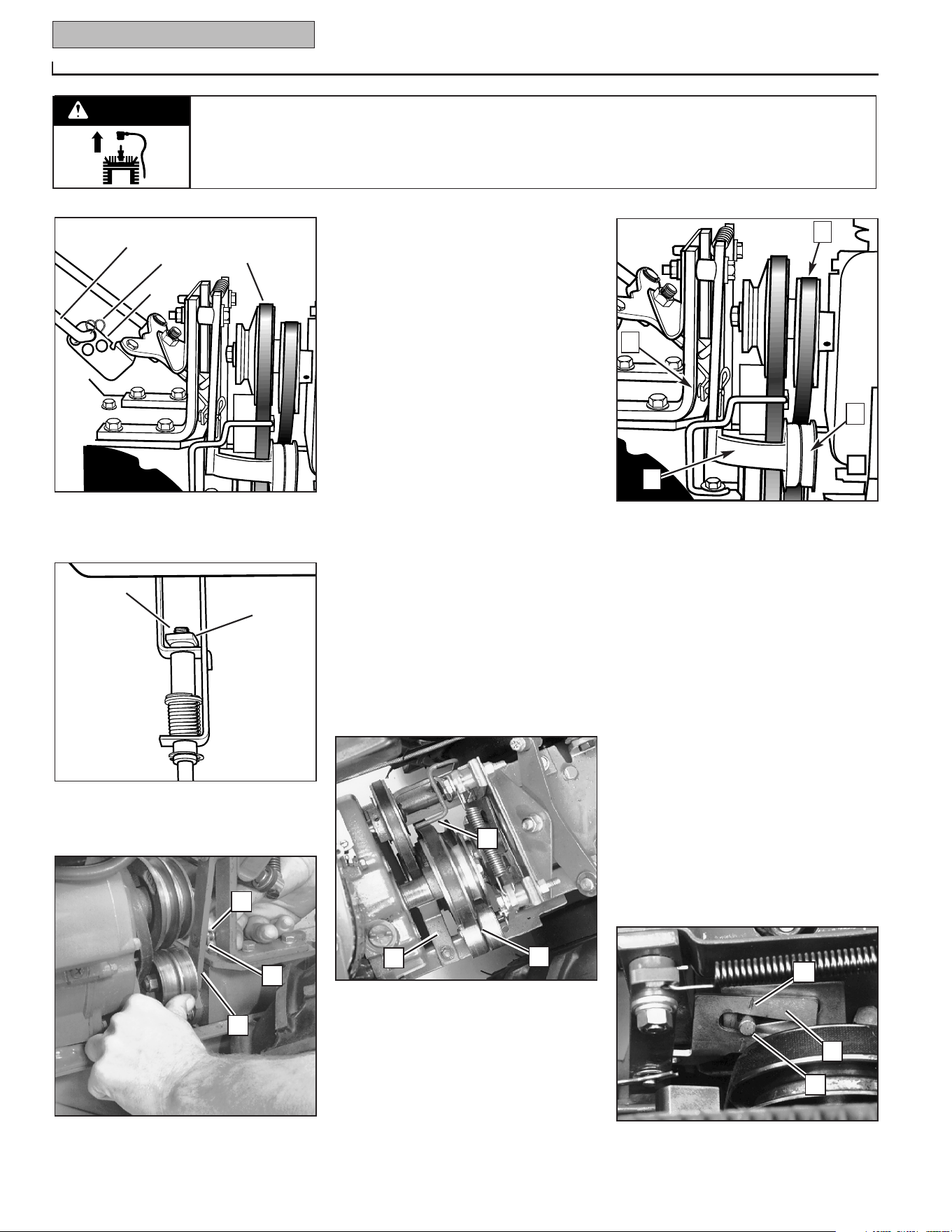
20 Section 5: Maintenance
Before inspecting, cleaning or servicing the machine, shut off engine, wait for all moving parts to come to
a complete stop, disconnect spark plug wire and move wire away from spark plug.
Failure to follow these instructions can result in serious personal injury or property damage.
WARNING
NOTE: While pushing inward on the
forward idler arm, be sure that the forward
drive belt is moved off to the right side of
the tiller. This creates more room to install
the clevis pin when the forward idler arm
is pushed inward.
IMPORTANT: When the clevis pin is
installed in the inner hole of the forward
adjustable link, the number of additional
belt tension adjustments are limited. If,
with future tension adjustments, you find
that you cannot screw the forward clutch
rod any farther into the rectangular nut on
the forward clutch bracket, it means that
the forward drive belt must be replaced.
Before doing so, the clevis pin must be
returned to the OUTSIDE hole in the
forward adjustable link.
8. Replace the forward drive belt in the
High speed groove (groove closest to
engine) or the Low speed groove (rear-
most) groove of the engine drive pulley
and in the matching groove of the trans-
mission pulley. Be sure the belt is to the
inside of the wire formed belt guide (I,
Figure 5-12) and to the inside of the
forward drive idler pulley (J).
9. Reinstall the belt cover and secure it
with the two nuts.
10. Readjust the forward drive belt tension
by following the instructions in Section 3:
Handlebar Height Adjustment.
To Check and Adjust Tension on the
Reverse Drive Belt:
1.
Remove the belt cover after first shut-
ting off the engine, disconnecting the
spark plug wire, and allowing the engine
and muffler to cool down.
2. Stand at the front of the tiller and use
your left hand to push the reverse idler
arm (K, Figure 5-13) inward as far as pos-
sible (the reverse idler pulley [L] is
attached to the reverse idler arm).
Hold the idler arm in this position and look
at the position of the belt tension guide
mark (M, Figure 5-14) that is stamped into
the face of the reverse adjustable link (N,
Figure 5-14).
• The tension is correct if the guide mark
(M, Figure5-14) is anywhere to the left of
the guide pin (O), as viewed from the
Figure 5-10: One or two threads on Forward
Clutch Rod should be exposed above rectan-
gular nut.
D
Threads
Figure 5-9: Disconnect Forward Clutch Rod
and move forward drive belt out of groove in
engine forward drive pulley.
A
C
(E) Remove belt
from groove
B
Figure 5-11: Remove clevis pin from outer
hole in forward adjustable link and move to
inner hole in link.
G
H
F
Figure 5-12: Top view of belts and pulleys.
Figure 5-13
I
V
J
P
K
L
R
Figure 5-14: While pushing reverse idler
arm inward, stand at engine end and
check position of guide mark (M) and
guide pin (O).
O
N
M
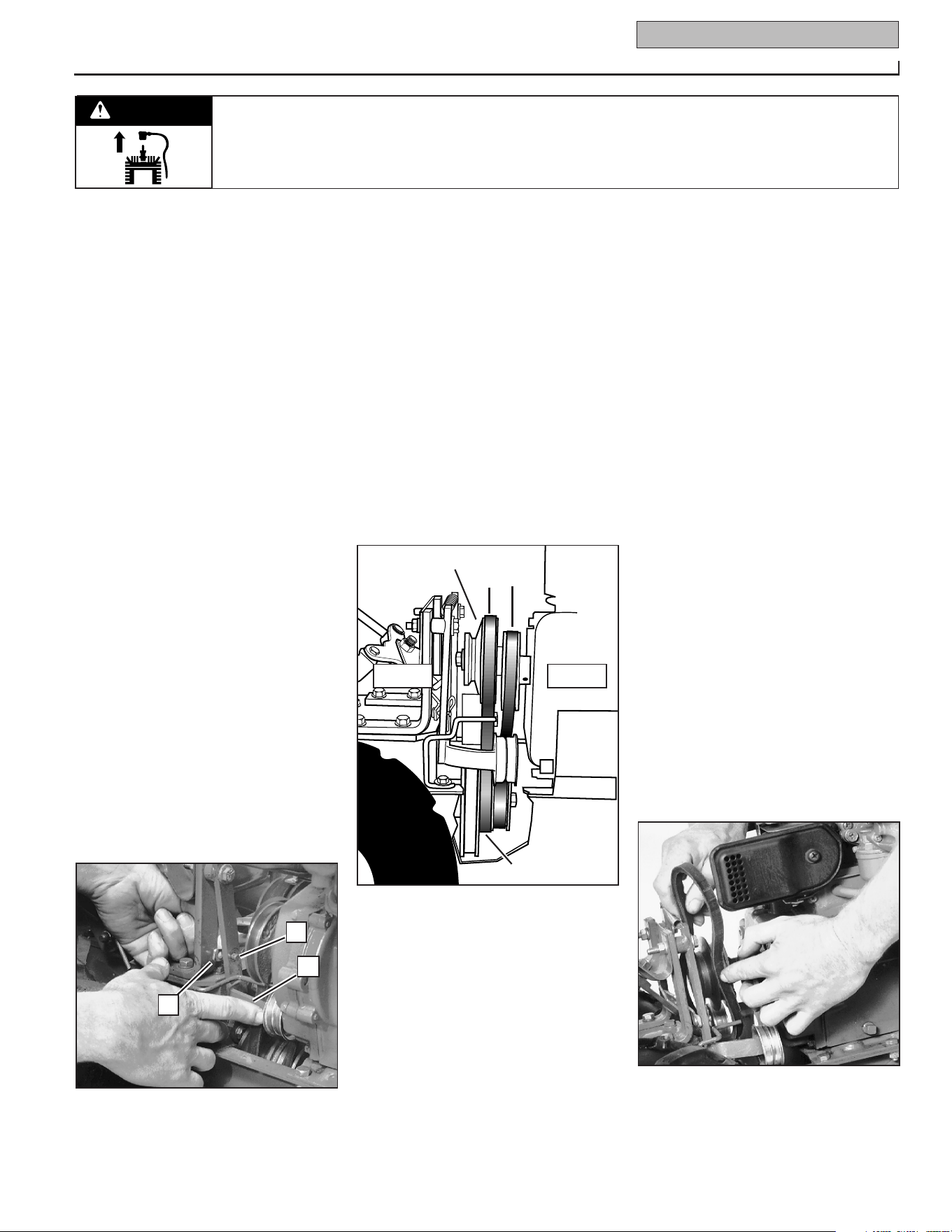
Section 5: Maintenance 21
Before inspecting, cleaning or servicing the machine, shut off engine, wait for all moving parts to come to
a complete stop, disconnect spark plug wire and move wire away from spark plug.
Failure to follow these instructions can result in serious personal injury or property damage.
WARNING
8. Reinstall the reverse belt (P, Figure 5-13)
on the reverse (upper) pulley, making sure
the belt is located to the inside of the
reverse idler pulley (L, Figure 5-13).
9. Reinstall the belt cover and secure it
with the two nuts.
IMPORTANT: If, in future tests for reverse
belt tension, the guide mark should again
align with or move to the right side of the
guide pin, it means that the reverse belt is
worn beyond adjustment. Before installing
a new belt, you must return the clevis pin
to the OUTSIDE hole in the reverse
adjustable link.
FORWARD DRIVE BELT REMOVAL
AND INSTALLATION
This model has two forward speeds (High
and Low) and one reverse speed. The
forward engine pulley (D, Figure 5-16) has
two grooves for the two forward speeds.
The reverse engine pulley (A, Figure 5-16)
has one groove for the one reverse speed.
The transmission pulley (C, Figure 5-16)
has three grooves. The groove closest to
the engine is for the reverse belt. The
middle groove is for the High speed
forward belt range; the rearmost groove is
for the Low speed forward belt range.
A. Removing the Forward Drive Belt:
1. Stop the engine, allow it to cool and
disconnect the spark plug wire before
working near the belts.
2. Remove the reverse drive belt
(A, Figure 5-16) by following the
Remov-
ing the Reverse Drive Belt instructions in
this section.
3. Move the forward drive belt (B, Figure
5-16) completely off the engine forward
drive pulley (D).
4. Slip the forward drive belt completely
off the transmission drive pulley (C, Figure
5-16) by moving it to the front of the
pulley.
5. Pull the forward drive belt up and off
the pulleys by feeding the bottom half of
the belt in between the engine and trans-
mission pulleys.
B. Installing the Forward Drive Belt:
1. The reverse drive belt must be removed
before installing the forward drive belt.
2. Slip the forward drive belt down
between the rear of the engine forward
drive pulley (D, Figure 5-16) and feed the
bottom half in between the engine and
transmission pulleys (see Figure 5-17). Be
sure that the belt is to the inside of the
forward idler pulley and forward belt guide
(see J and I, Figure 5-12).
front of the unit (not the operator’s posi-
tion). If the belt tension is correct, rein-
stall the belt cover and secure it with the
two nuts.
• If the guide mark is aligned with the
guide pin, or moves to the right side of
the guide pin, then the belt is too loose
and the tension must be readjusted as
described next.
3. The reverse idler pulley (L, Figure 5-13)
regulates the tension that is applied to the
reverse drive belt (P). The following
adjustment will allow the reverse idler
pulley to apply more tension to a loose
belt.
4. Remove the belt cover.
5. Slip the reverse belt (P, Figure 5-13) off
the engine-driven reverse (upper) pulley.
6. On the right side of the unit (as viewed
from operator’s position), remove the
hairpin cotter from the clevis pin (R,
Figure 5-13) that connects the reverse
idler arm (K) to the reverse adjustable link.
Push inward on the reverse idler arm (K)
and remove the clevis pin (R).
7. There are two holes in the reverse
adjustable link (S, Figure 5-15). Push
inward on the reverse idler arm (K) and
install the clevis pin (R) through the
inner
hole in the reverse adjustable link (S) and
out through the single hole in the reverse
idler arm (K). Secure the clevis pin with
the hairpin cotter.
Figure 5-17: Install forward drive belt over
rear of engine forward pulley and bring lower
half of belt down and in front of transmission
pulley.
Figure 5-15: Installing clevis pin in inside
hole of reverse adjustable link.
S
R
K
Figure 5-16: Belt drive system.
A
B
C
D
FRONTREAR
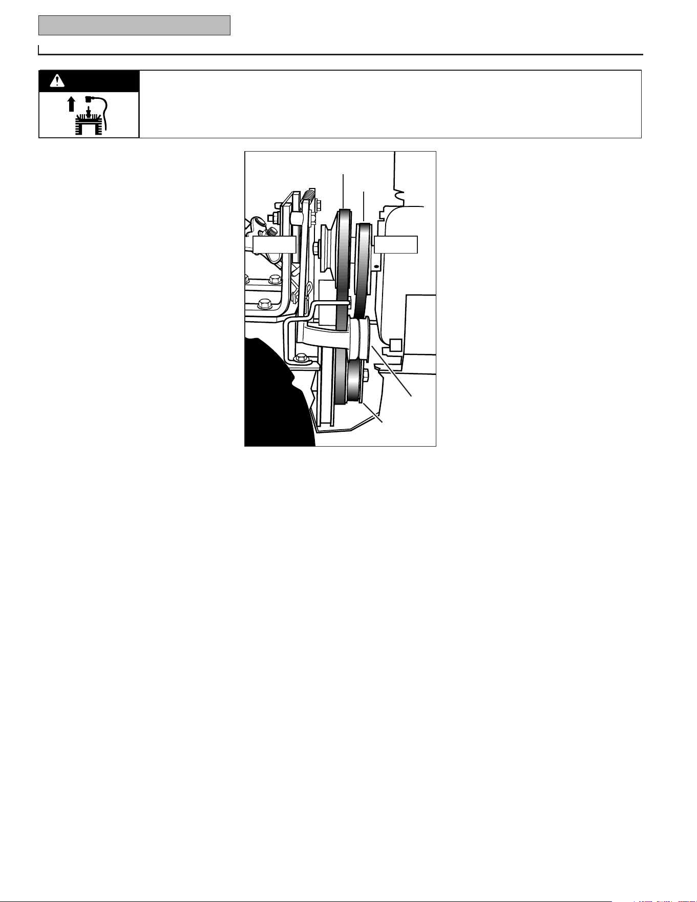
22 Section 5: Maintenance
Before inspecting, cleaning or servicing the machine, shut off engine, wait for all moving parts to come to
a complete stop, disconnect spark plug wire and move wire away from spark plug.
Failure to follow these instructions can result in serious personal injury or property damage.
WARNING
3. Slip the forward drive belt down and
over the front of the transmission pulley
(C, Figure 5-16). NOTE: For additional
working room, loosen the reverse belt
guide (V, Figure 5-12) and twist it out of
the way.
4. Put the lower half of the belt into the
High speed groove (middle groove) or the
Low speed groove (rearmost groove) of
the transmission pulley (C, Figure 5-16).
5. Put the upper half of the belt in the High
speed groove (groove closest to engine)
or the Low speed groove (rearmost
groove) of the engine forward drive pulley
(D, Figure 5-16).
IMPORTANT: Make sure that the forward
drive belt is to the inside of the wire belt
guide (I, Figure 5-12) and the forward idler
pulley (J).
6. If you loosened the belt guide, wait until
the reverse drive belt is installed before
securing the belt guide.
7. Install the reverse drive belt.
8. Install the belt cover and secure it with
the two nuts.
9. If you installed a new belt, check the
tension after two hours of operation
(every 10 hours thereafter).
REVERSE DRIVE BELT REMOVAL AND
INSTALLATION
NOTE: The forward drive belt must be
installed before installing the reverse drive
belt.
A. Removing the Reverse Drive Belt:
1.
Stop the engine and allow it to cool
before working near the belts. Be sure the
spark plug wire is disconnected and on
electric start models the ignition key is
removed.
2. Remove the belt cover by removing the
two nuts. For easier access to the trans-
mission (lower) pulley, remove the trans-
mission cover located below the trans-
mission pulley.
3. Slip the reverse belt off the engine
reverse pulley (A, Figure 5-18). If neces-
sary, work the belt off the pulley with your
left hand while pulling the engine recoil
starter rope with your right hand.
4. Push the upper half of the reverse belt
downward to create slack in the belt. Then
reach underneath the transmission and
slip the belt off the front of the transmis-
sion pulley (B, Figure 5-18).
5. Pull the belt up and past the engine
reverse pulley (A, Figure 5-18).
B. Installing the Reverse Drive Belt:
1. Slip the reverse belt down between the
engine reverse pulley (A, Figure 5-18) and
the engine forward drive pulley (C).
2. Loop the bottom half of the belt over
the front of the transmission pulley (B,
Figure 5-18) and seat the belt in the front
groove of the pulley.
3. Place the belt to the inside of the
reverse idler pulley (D, Figure 5-18) and
the reverse belt guide (V, Figure 5-12).
Then slip the upper end into the groove of
the engine reverse pulley (A, Figure 5-18).
4. If the reverse belt guide (V, Figure 5-12)
was loosened previously, center the belt
guide on the belt and tighten the mounting
screw securely.
5. Install the belt cover and secure it with
the two nuts. If the lower transmission
cover was removed, reinstall it with the
four self-tapping screws.
Figure 5-18: Removing and installing reverse
belt.
A
C
B
D
FRONTREAR

Section 5: Maintenance 23
Before inspecting, cleaning or servicing the machine, shut off engine, wait for all moving parts to come to
a complete stop, disconnect spark plug wire and move wire away from spark plug.
Failure to follow these instructions can result in serious personal injury or property damage.
WARNING
TROUBLESHOOTING
Before performing any troubleshooting procedures, refer to the appropriate safety, operating or maintenance instructions in this
Manual or in the Engine Owner’s Manual. Contact your local authorized engine service dealer for engine service. Contact your local
authorized tiller dealer or the factory for all other service problems.
PROBLEM POSSIBLE CAUSE CORRECTION
Engine does 1. Spark plug wire disconnected. 1. Reconnect wire.
not start. 2. Engine Throttle Control Lever incorrectly set. 2. Put lever in START position.
3. Fuel tank empty. 3. Add fuel.
4. Choke control (if so equipped) in incorrect position. 4. See Engine Owner’s Manual.
5. Stale gasoline. 5. Drain fuel and add fresh fuel.
6. Dirty air filter(s). 6. Clean or replace filter(s).
7. Defective or incorrectly gapped spark plug. 7. Inspect spark plug.
8. Carburetor out of adjustment. 8. See Engine Service Dealer.
9. Misadjusted throttle control cable. 9. See Engine Service Dealer
10.Dirt or water in fuel tank. 10 See Engine Service Dealer.
Engine runs poorly. 1. Defective or incorrectly gapped spark plug. 1. Inspect spark plug (see Engine Owner’s Manual).
2. Dirty air filter(s). 2. Clean or replace (see Engine Owner’s Manual).
3. Carburetor out of adjustment. 3. See Engine Service Dealer.
4. Stale gasoline. 4. Replace with fresh gasoline.
5. Dirt or water in fuel tank. 5. See Engine Service Dealer.
6. Engine cooling system clogged. 6. Clean air cooling system (see Engine Owner’s Manual).
Engine overheats. 1. Engine cooling system clogged. 1. Clean air cooling area (see Engine Owner’s Manual).
2. Carburetor out of adjustment. 2. See Engine Service Dealer.
3. Oil level is low. 3. Check oil level (see Engine Owner’s Manual).
Engine does not
shut off.
Misadjusted throttle control cable. See Engine Owner’s Manual or Engine Service Dealer.
Wheels and Tines 1. Improper use of controls. 1. Review Sections 3 and 4.
will not turn. 2. Forward Drive: Misadjusted forward clutch rod. 2. See Handlebar Height Adjustment, Section 3.
3. Reverse Drive: Broken or misadjusted belt. 3. Replace belt or adjust belt tension (Section 5).
4. Worn, broken, or misadjusted drive belt(s). 4. See
Checking Drive Belt Tension, Section 5.
5. Internal transmission wear or damage. 5. Contact local dealer or the factory.
6. Bolt and key loose in transmission pulley. 6. Tighten bolt; check that key is in place.
Tines turn, but 1. Wheel mounting hardware missing. 1. Replace hardware.
wheels don’t. 2. Bolt and key loose in transmission pulley. 2. Tighten bolt; check that key is in place.
3. Internal transmission wear or damage. 3. Contact local Dealer or the Factory.
4. Misadjusted wheel gear cable. 4. See
Wheel Gear Cable Adjustment, Section 5.
5. Wheel Gear Lever not fully engaged. 5. Engage lever (see Section 3).
Wheels Turn, but 1. Tine holder mounting hardware missing. 1. Replace hardware.
Tines Don’t. 2. Internal transmission wear or damage. 2. Contact local Dealer or the Factory.
Poor tilling 1. Worn tines. 1. See Tines (Section 5).
performance. 2. Improper Depth Regulator setting. 2. See Tilling Tips & Techniques, Section 4.
3. Incorrect throttle setting or belt range speed. 3. See Section 4.
4. Belt(s) slipping. 4. See Checking Drive Belt Tension, Section 5.
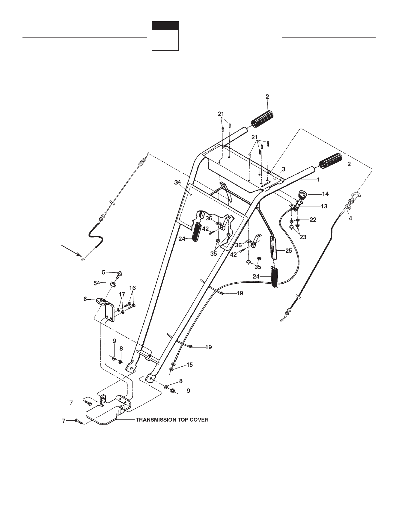
HANDLEBAR ASSEMBLY and CONTROL LEVERS
10
(See page 28,
Ref. 47, for
attachment
screw)
Parts List
6
Section

Parts List 25
Model 675B
REF. PART
No. No. DESCRIPTION QTY.
REF. PART
No. No. DESCRIPTION QTY.
1 1918811 Handlebars (Incl. Refs. 2, 3 & 3A)....... 1
2 GW-9126 Grip ..................................................... 2
3 777I22071 Decal, Control Panel ........................... 1
3A 777D006865 Decal, Model Name/Logo .................... 1
4 1916639 Reverse Clutch Control Cable .............. 1
5 1186347 Height Adjustment Screw ................... 1
5A GW-9955 Washer, Keyed..................................... 1
6 1900475 Bracket, Handlebar Height Adjustment 1
7 710-0514 Hex Hd. Screw, 3/8-16 x 1*................. 2
8 736-3050 Washer, Plain (flat) 3/8, S.A.E. ............ 2
9 712-3000 Hex Locknut, 3/8-16 ............................ 2
10 1918791 Cable, Forward Clutch Control ............. 1
13 GW-9442 Wheel Gear Control and Cable Assy.
(Incl. Refs. 14, 15, 19, 21, 22 & 23) 1
14 GW-9057 Knob, Wheel Gear Control Lever.......... 1
15 1186211 Hex Nut, 5/16-24 ................................. 2
16 710-0216 Hex Hd. Screw, 3/8-16 x 3/4*.............. 2
17 736-0169 Lockwasher, 3/8 .................................. 2
19 725-0157 Cable Ties, Plastic................................ 2
21 1114748 Round Hd. Screw, #10-32 x 1/2 .......... 6
22 1100240 Lockwasher, #10 ................................. 2
23 1186208 Hex Nut, #10-32 .................................. 2
24 GW-9390 Grip ..................................................... 2
25 1918840 Bail, Forward Clutch Control (Incl.
two Ref. 24)..................................... 1
35 GW-9853 Sems Nut............................................. 4
36 GW-20806 Bracket, Bail Support........................... 2
42 710-0599 Hex Flange Screw, self-tapping,
1/4-20 x 1/2*................................... 2
HANDLEBAR ASSEMBLY and CONTROL LEVERS
* Specify GRADE 5 if ordering part locally.
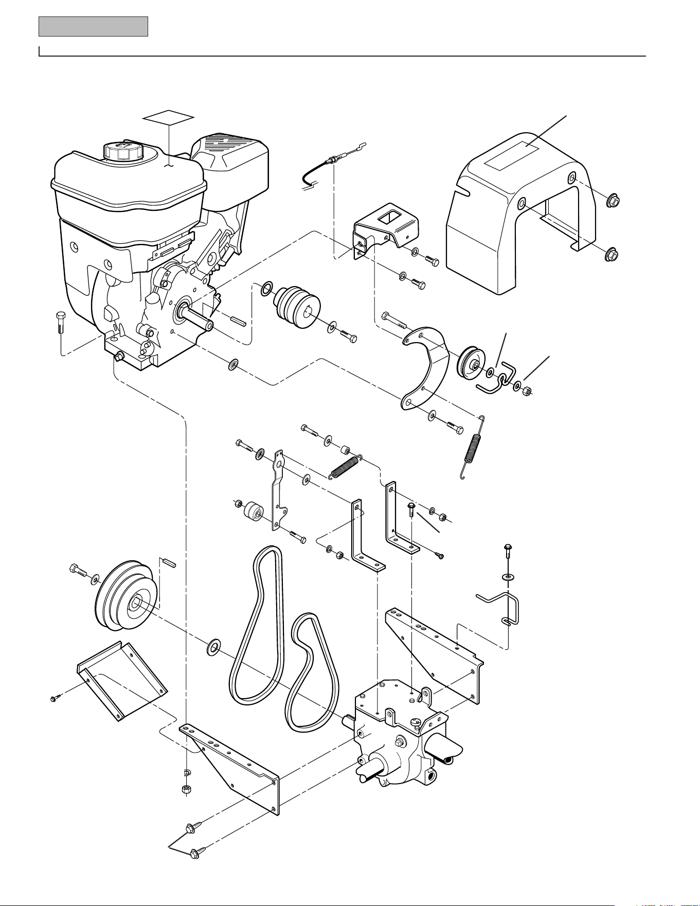
26 Parts List
Model 675B
ENGINE, SUPPORT BRACKETS, PULLEYS, BELTS, BELT COVER
Reverse
Clutch Cable
2
6
5
7
7
3
4
13
14
15
16
17
16
52
21
25
24
23
8
39
46
20
20
43
53
54
41
44
51
43
44
37
38
47
1
45
45
49
50
40
42
48
12
26
27
3
28
29
30
9
22
18
56
11
10
9
2
35
36
(Screw, Ref. 47, secures
Forward Clutch Cable –
page 26, Ref. 10)

Parts List 27
Model 675B
ENGINE, SUPPORT BRACKETS, PULLEYS, BELTS, BELT COVER
1 710-0395 Hex Hd. Screw, 5/16–18 x 2-1/4 ......... 1
2 1917326 Bracket, Clutch Cable .......................... 1
3 736-0119 Lockwasher–5/16................................ 6
4 710-0107 Hex Hd. Screw, 5/16-24 x 1/2 ............. 2
5 777S30651 Decal, Hot Surfaces/Belt Warning ....... 1
6 1917139 Cover (Incl. Ref. 5).............................. 1
7 712-3004A Flange Lock Nut, 5/16-18.................... 2
8 1108841 Key, 3/16 x 1-1/2 ................................ 1
9 GW-1138-1 Shim ................................................... 1
10 1916520 Pulley, Engine Drive ............................ 1
11 GW-9944 Belleville Washer................................. 2
12 GW-9572 Hex Hd. Screw, 5/16–24 x 1-1/8 ......... 1
13 710-3103 Hex Hd. Screw, 5/16–18 x 2 ............... 1
14 1918731 Reverse Idler Arm ............................... 1
15 1916535 Pulley, Reverse Idler ........................... 1
16 1107382 Flat Washer, 5/16................................ 2
17 1916725 Belt Guide, Wire Formed .................... 1
18 710-0117 Hex Head Screw, 5/16-24 x 1.............. 1
19 1917746 Washer, Shoulder ............................... 1
20 GW-9929 Washer, Flat, 1-1/8.............................. 3
21 1916728 Spring, Reverse Return....................... 1
22 1916522 Transmission Pulley............................ 1
23 GW-1440 Support Washer.................................. 1
24 1918812 Reverse Clutch Belt............................. 1
25 1909404 Forward Clutch Belt............................. 1
26 1900396 Self-tapping Screw, #10-32 x 1/2, ...... 4
27 GW-20339 Guard, Belts/Pulleys............................ 1
28 712-0267 Hex Nut, 5/16–18................................ 4
29 1186329 Hex Flange Screw, 5/16-18 x 3/4* ...... 4
30 1916797 Engine Support Bracket, left side ........ 1
31 1916796 Engine Support Bracket, right side...... 1
35 710-0805 Hex Hd. Screw, 5/16–18 x 1-1/2 ......... 5
36 777I20942 Decal, Stabilization.............................. 1
37 1918774 Mounting Bar ...................................... 2
38 GW-90063 Hex Flange Screw, 5/16-18 x 1 ........... 4
39 710-3037 Hex Hd. Screw, 5/16-18 x 2-1/4*........ 1
40 736-0275 Flat Washer, 5/16'............................... 1
41 1918846 Belt Guide, Pony ................................. 2
42 GW-55088 Pivot Bushing...................................... 2
43 736-0119 Lockwasher, 5/16................................ 2
44 712-0267 Hex Nut, 5/16-18................................. 2
45 1917746 Washer, Shoulder ............................... 2
46 1918744 Idler Arm, Forward Tiller Direction...... 1
47 1767754 Screw, self tapping, #10-24 ................ 1
48 1916727 Spring ................................................. 1
49 712-3000 Hex Locknut, 5/16-18 ......................... 1
50 GW-9090 Idler Pulley, Forward .......................... 1
51 710-0347 Screw, 3/8-16 x 1-3/4 ......................... 1
52 712-0158 Hex Lock Nut, 5/16-18 ........................ 1
53 1754128 Screw, 1/4-20 x 3/4 ............................ 1
54 736-0463 Flat Washer–1/4.................................. 1
REF. PART
No. No. DESCRIPTION QTY.
REF. PART
No. No. DESCRIPTION QTY.
* Specify GRADE 5 if ordering part locally.
** See your local authorized engine service dealer for engine parts or
service. Refer to engine nameplate for engine type and code
information.
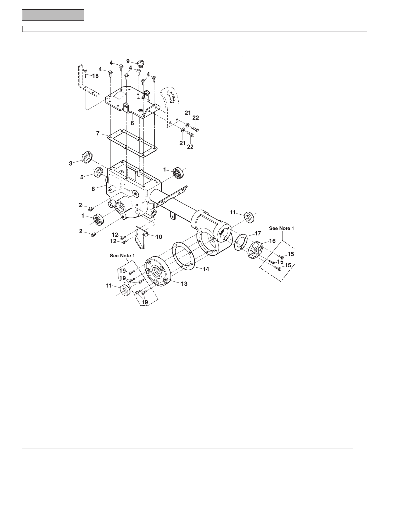
28 Parts List
Model 675B
TRANSMISSION HOUSING, COVERS, SEALS, GASKETS, PLUGS
NOTE 1: These screws are a special sealing screw
that cannot be reused without risking the loss of
transmission oil. If these screws are loosened or
removed, they must be replaced with new screws.
1 721-04035 Oil Seal (Double Lip), Wheel Shaft ...... 2
2 1105620 Pipe Plug, 1/4, ................................... 2
3 721-04001 Seal, Transmission Bore ..................... 1
4 1186329 Hex Flange Screw, 5/16-18 x 3/4* ...... 6
5 1983632 Oil Seal, Input Pinion Shaft ................. 1
6 GW-11513 Transmission Cover (Incl. four Ref. 18
and two ea. Refs. 21 & 22).............. 1
7 GW-20694 Gasket, Transmission Top Cover ........ 1
8 619-04010 Transmission Case Assy. .................... 1
9 GW-9467 Plug .................................................... 1
10 1917101 Mounting Plate, Wheel Clutch Cable ... 1
11 721-04035 Oil Seal, Tiller Shaft............................. 2
12 710-04049 Hex Flange Screw, 5/16-18 x 5/8* ...... 2
13 GW-20873 Tiller Housing Cover, left side ............. 1
14 GW-1129-1 Gasket, Tiller Housing Cover, .010"
(fits all covers) ................................ A/R
15 1915089 Screw Kit: Incl. three 1/4-20 x 7/8
Self-Sealing Screws ........................ A/R
16 GW-1115 Rear Bearing Cap ................................ 1
17 GW-1124-2 Gasket, Rear Bearing Cap, .010"
Thick ............................................... A/R
18 GW-90063 Hex Flange Screw, 5/16-18 x 1* ......... 4
19 1915087 Screw Kit: Incl. five 1/4-20 x 5/8
Self-Sealing Screws ........................ A/R
21 736-0169 Lockwasher, 3/8.................................. 2
22 710-0216 Hex Hd. Screw, 3/8-16 x 3/4* ............. 2
REF. PART
No. No. DESCRIPTION QTY.
REF. PART
No. No. DESCRIPTION QTY.
* Specify GRADE 5 if ordering part locally.
A/R – As Required
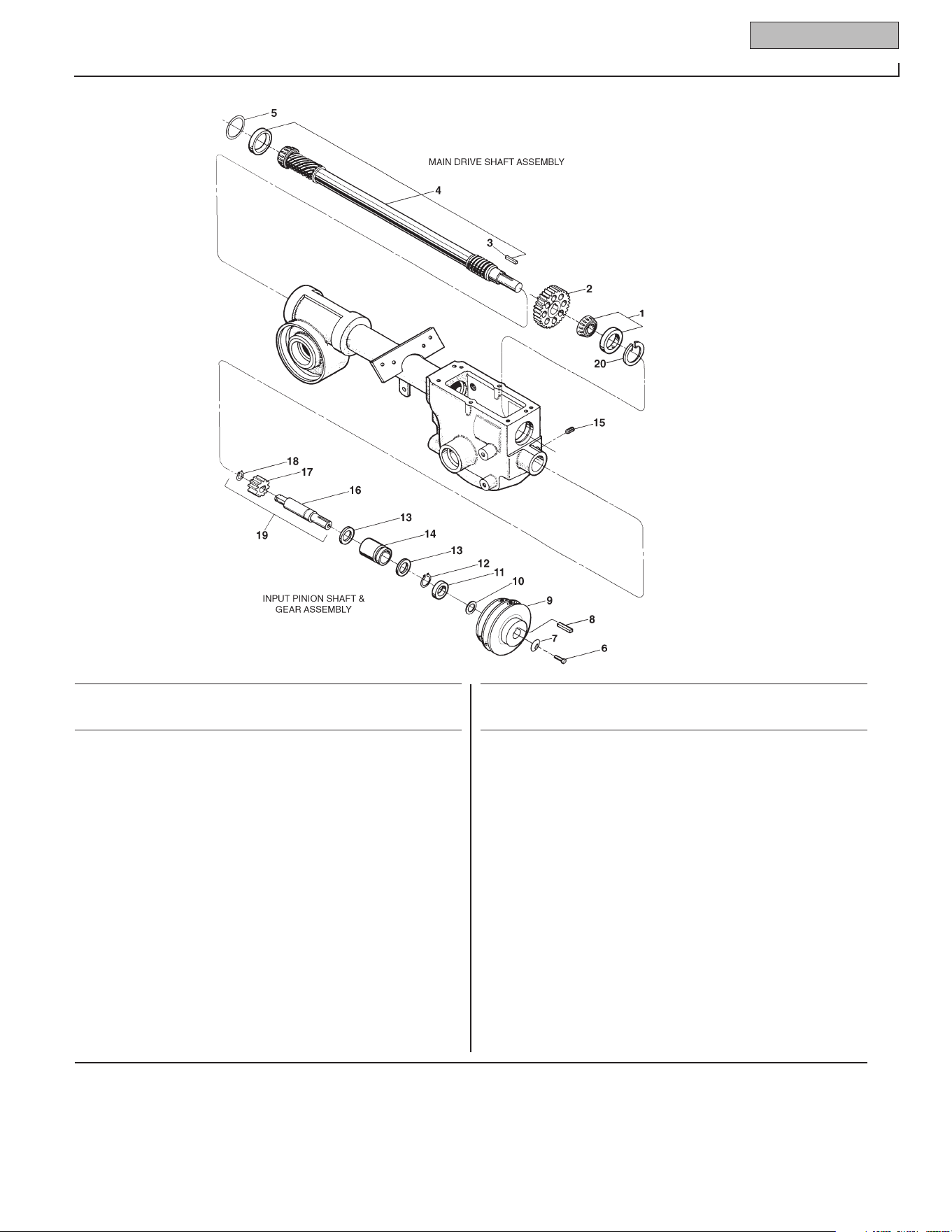
Parts List 29
Model 675B
MAIN DRIVE SHAFT
1 GW-1714 Bearing, Tapered Roller with Race .... 1
2 GW-20718 Spur Gear .......................................... 1
3 GW-9301 Key, 3/16 sq. x 1 ............................... 1
4 1916597 Main Drive Shaft (Drive shaft is one-
piece with integral, single-lead,
work-hardened front worm, and
integral, six-lead, work-hardened
rear worm. Also includes pressed-
on GW-1714 and GW-9301).......... 1
5 GW-1224-1 Shim, Rear Bearing Cap, .010" thick
(see Note below) ........................... A/R
5 GW-1224-2 Shim, same as above, but .030" thick
(see Note)...................................... A/R
5 GW-1224-3 Shim, same as above, but .005" thick
(see Note)...................................... A/R
... GW-1325C Shim Set (Incl. two GW-1224-1; two
1224-2 and one GW-1224-3) ........ A/R
INPUT PINION SHAFT & GEAR ASSEMBLY
6 GW-9572 Hex Hd. Screw, 5/16-24 x 1-1/8* ...... 1
7 GW-9944 Washer, Disc Spring (concave
surface faces pulley)...................... 1
8 1108841 Key, 3/16 sq. x 1-1/2......................... 1
9 1916522 Transmission Drive Pulley................. 1
10 GW-1440 Support Washer ................................ 1
11 721-04044 Oil Seal, Input Pinion Shaft................ 1
12 1113527 Retaining Ring (external) .................. 1
13 GW-9953 Thrust Washer................................... 2
14 GW-9428 Bushing............................................. 1
15 GW-9677 Set Screw, 5/16-18 x 3/8*................. 1
16 GW-20791 Input Pinion (steel shaft)................... 1
17 GW-20792 Input Pinion Gear .............................. 1
18 GW-9093 Retaining Ring (external) l................. 1
19 GW-20799 Pinion Assy. (Incl. one each Refs. 16,
17 and 18 ...................................... A/R
20 GW-9517 Retaining Ring (internal) .................. 1
REF. PART
No. No. DESCRIPTION QTY.
REF. PART
No. No. DESCRIPTION QTY.
NOTE: Shim between drive shaft rear bearing and rear bearing cap to achieve 5-to-10 thousandths of an inch (.005-.010) end play on drive shaft.
A/R - As Required
* Specify GRADE 5 if ordering part locally.
DRIVE SHAFT, INPUT PINION SHAFT and GEAR ASSEMBLIES
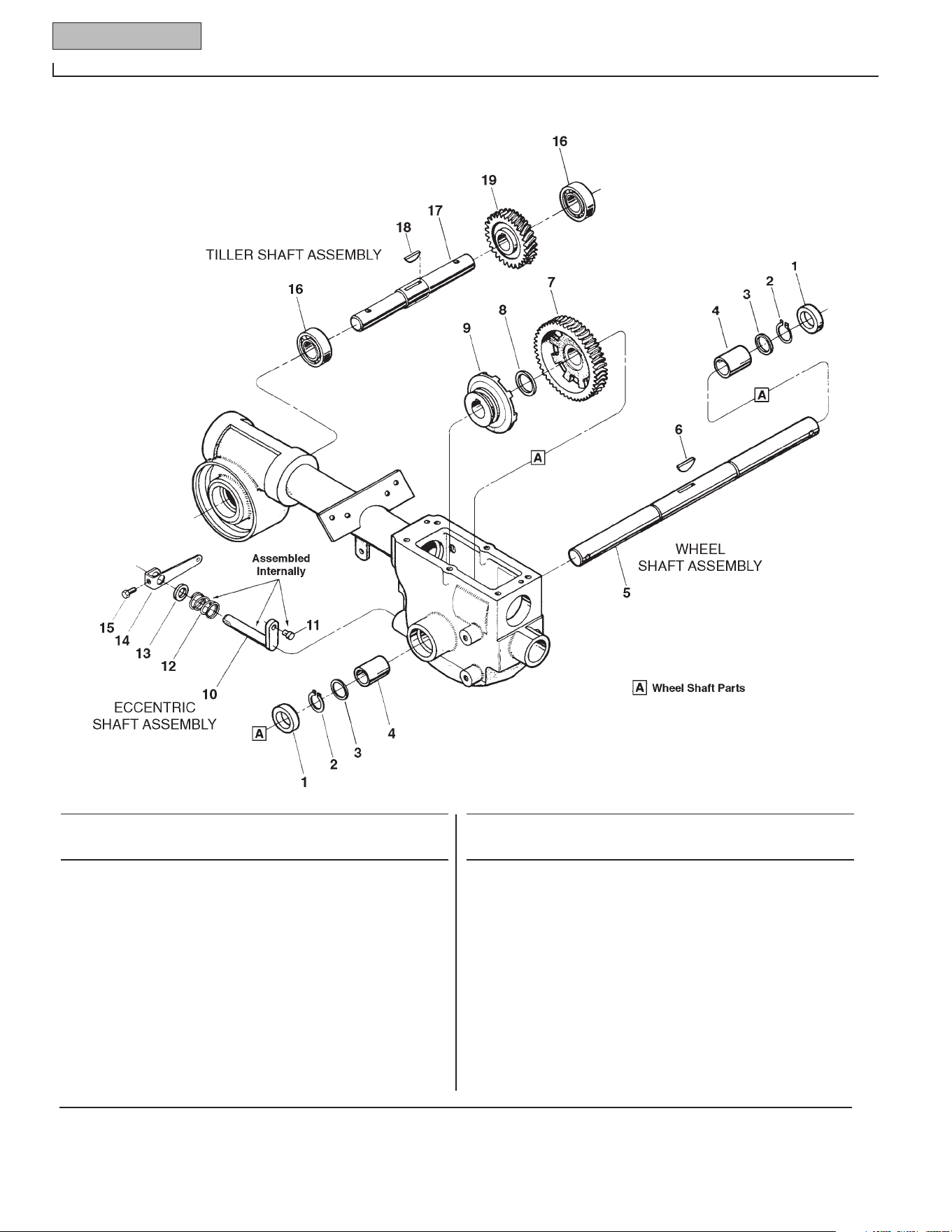
30 Parts List
Model 675B
WHEEL SHAFT, ECCENTRIC SHAFT and TILLER SHAFT ASSEMBLIES
REF. PART
No. No. DESCRIPTION QTY.
REF. PART
No. No. DESCRIPTION QTY.
1 721-04031 Oil Seal.............................................. 2
2 1909950 Retaining Ring (heavy-duty, external) 2
3 GW-1166-1 Shim, 1-1/64 I.D., .062" thick ............ A/R
--- GW-1166-2 Shim, as above, but .030" thick ......... A/R
--- GW-1166-3 Shim, as above, but .015" thick ......... A/R
--- GW-1166-4 Shim, as above, but .010" thick ......... A/R
4 GW-1086 Bushing............................................. 2
5 711-04091 Wheel Shaft (Incl. Ref. 6) .................. 1
6 GW-9373 Hi-Pro Key, 1/4 x 1-5/16.................... 1
7 GW-20914 Wheel Drive Worm Gear (cast-iron) .. 1
8 GW-9935 Shim (between key and gear),
1.016 I.D. x 1.468 O.D. x .062
Thick.............................................. 1
9 GW-20712 Wheel Drive Clutch (cast-iron) .......... 1
10 611-04002 Eccentric Shaft .................................. 1
11 GW-1442 Pin, Eccentric Shaft ........................... 1
12 GW-9055 Spring ............................................... 1
13 721-04034 Oil Seal.............................................. 1
14 786-04001 Eccentric Shaft Lever......................... 1
15 710-3013 Hex Hd. Screw, 1/4-20 x 1/2* ........... 1
16 741-3037 Ball Bearing ....................................... 2
17 711-04130 Tiller Shaft (Incl. Ref. 18) .................. 1
18 GW-1104 Woodruff Key, 1/4 x 1-1/4................. 1
19 1904279 Tiller Drive Worm Gear (bronze) ....... 1
* Specify GRADE 5 if ordering part locally.
A/R - As Required
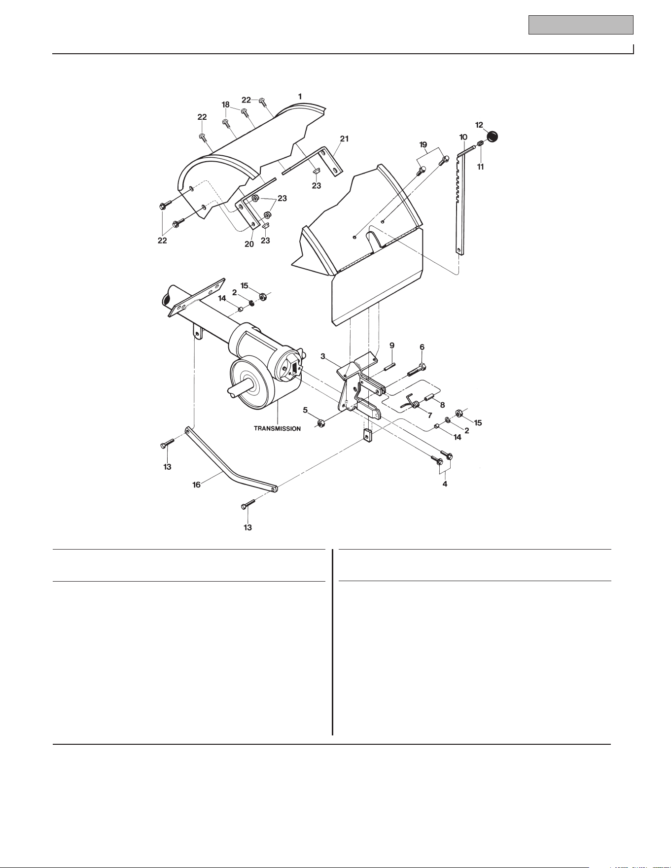
Parts List 31
Model 675B
1 686-04021 Hood, Tine .......................................... 1
2 736-0169 Lockwasher, 3/8.................................. 2
3 GW-2525 Bracket, Hood & Depth Regulator ....... 1
4 710-04049 Hex Hd. Flg. Screw, 5/16-18 x 5/8* .... 2
5 712-0291 Hex Lock Nut, 1/4-20 .......................... 1
6 710-0597 Hex Hd. Screw, 1/4-20 x 1* ................ 1
7 GW-9384 Spring, Depth Regulator Plunger ........ 1
8 GW-9534 Spacer................................................. 1
9 1185469 Roll Pin (spiral), 1/4 x 1 ..................... 1
10 1916186 Bar Assembly, Depth Adjustment........ 1
11 GW-9120 Retaining Ring (Tolerance Ring) ......... 1
12 GW-9119 Knob, Depth Regulator (Incl. Ref. 11). 1
13 710-3005 Hex Hd. Screw, 3/8-16 x 1-1/4*.......... 2
14 GW-1113-1 Bushing (spacer)................................. 2
15 712-3017 Hex Nut, 3/8-16................................... 2
16 GW-20775 Drag Bar, Depth Regulator ................. 1
18 710-0759 Hex Hd. Screw, self-tapping,
5/16-18 x 1/2* ................................ 2
19 710-0599 Hex Hd. Flg. Screw, self-tapping,
1/4-20 x 1/2* .................................. 2
20 1916700 Support Bracket, Left-Side.................. 2
21 1916701 Support Bracket, Right-Side ............... 1
22 1186328 Hex Hd. Screw, 5/16-18 x 5/8 ............. 6
23 1186391 Hex Nut, 5/16-18 ................................ 6
REF. PART
No. No. DESCRIPTION QTY.
REF. PART
No. No. DESCRIPTION QTY.
* Specify GRADE 5 if ordering part locally.
HOOD, BRACKET AND DEPTH REGULATOR
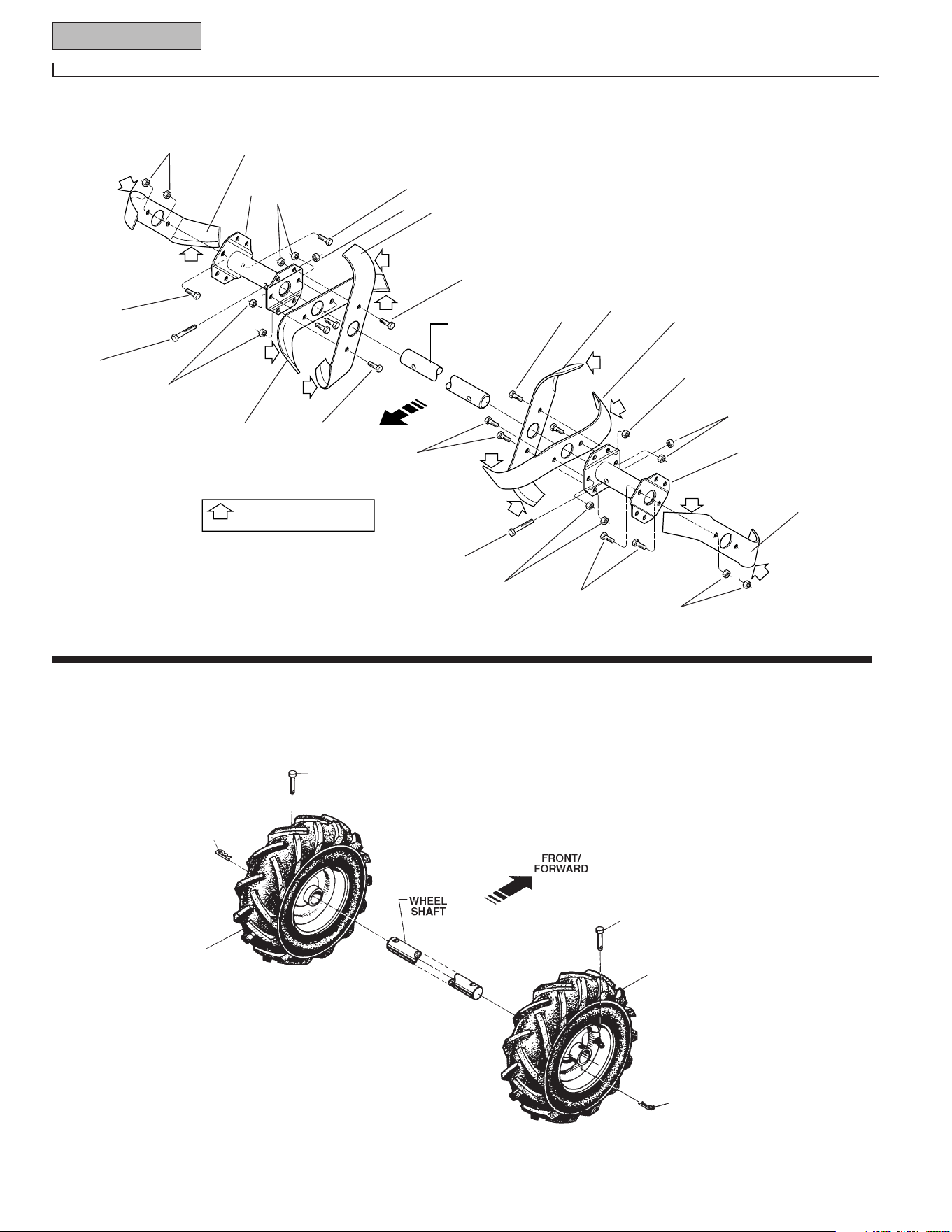
32 Parts List
Model 675B
ENGINE
TINE
SHAFT
DENOTES CUTTING EDGE
OF TINE
11
12
9
10
12
11
WHEELS
1
3
5
5
8A
7
7
1
3
3
1
1
1
1
2
7
2
2
1
3
3
3
3
3
8
OPERATOR
POSITION
TINES
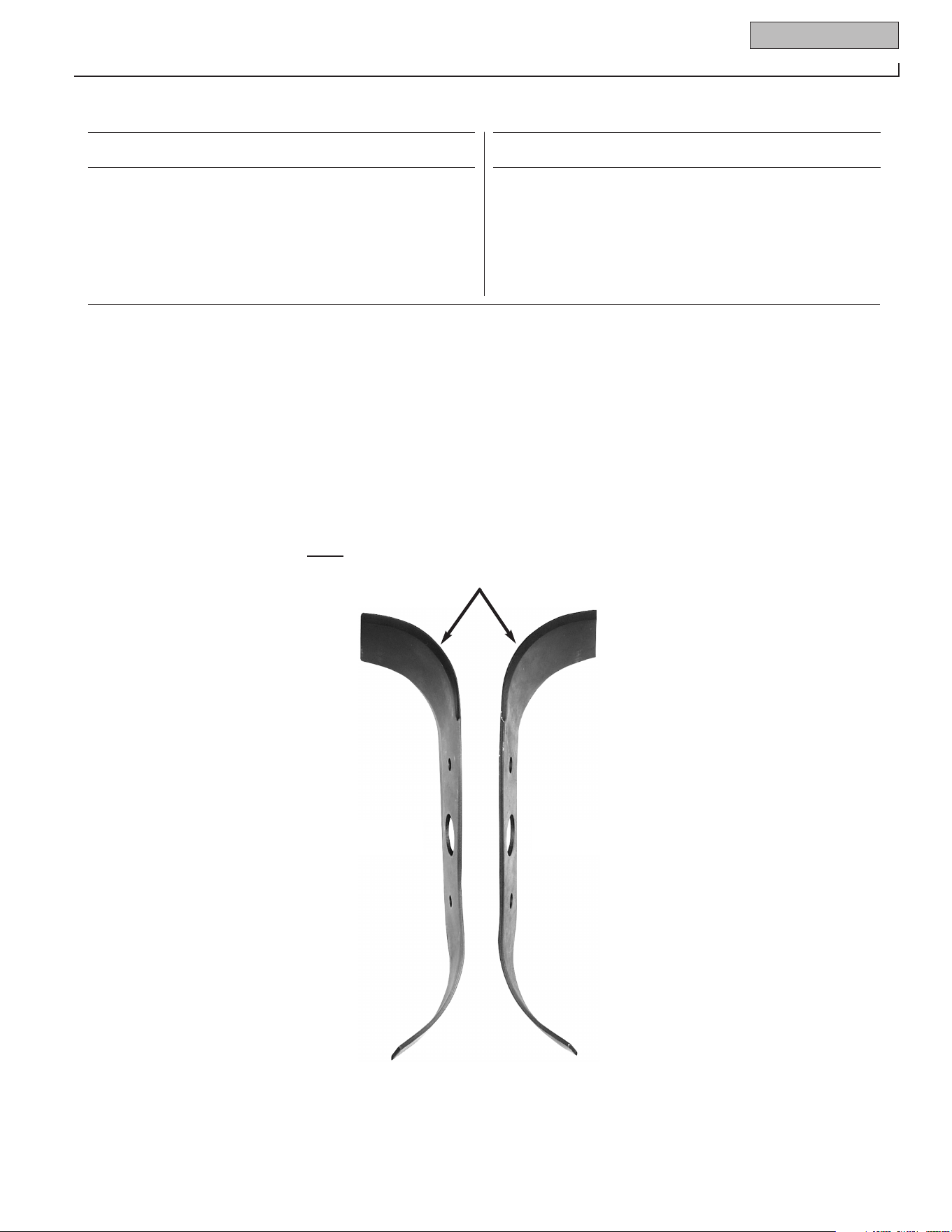
Parts List 33
Model 675B
1 1100068 Hex Hd. Screw, 3/8-16 x 3/4* ............. 12
2 1985101 Tine – right-hand ................................ 3
3 1110108 Hex Lock Nut, 3/8-16 .......................... 14
5 710-3096 Hex Hd. Screw, 3/8-16 x 2, Grade 8.... 2
7 1985100 Tine – left-hand................................... 3
8 1916693 Tine Holder, left-side........................... 1
8A 1916694 Tine Holder, right-side ........................ 1
9 634-04033 Wheel & Tire Assy., left-side............... 1
10 634-04032 Wheel & Tire Assy., right-side ............ 1
11 GW-9380 Clevis Pin, .312 x 1-3/4 long ............... 2
12 GW-9338 Hitch Pin ............................................. 2
IMPORTANT: LEFT and RIGHT sides of tiller are determined by standing in the operator
position (BEHIND THE HOOD) and facing the direction of forward travel.
RIGHT-HAND TINELEFT-HAND TINE
(TOP)
(BOTTOM)
MOUNT TINES SO THE CUTTING EDGE AT THE
TOP OF EACH TINE FACES THE OPERATOR
REF. PART
No. No. DESCRIPTION QTY.
REF. PART
No. No. DESCRIPTION QTY.
TINES & WHEELS
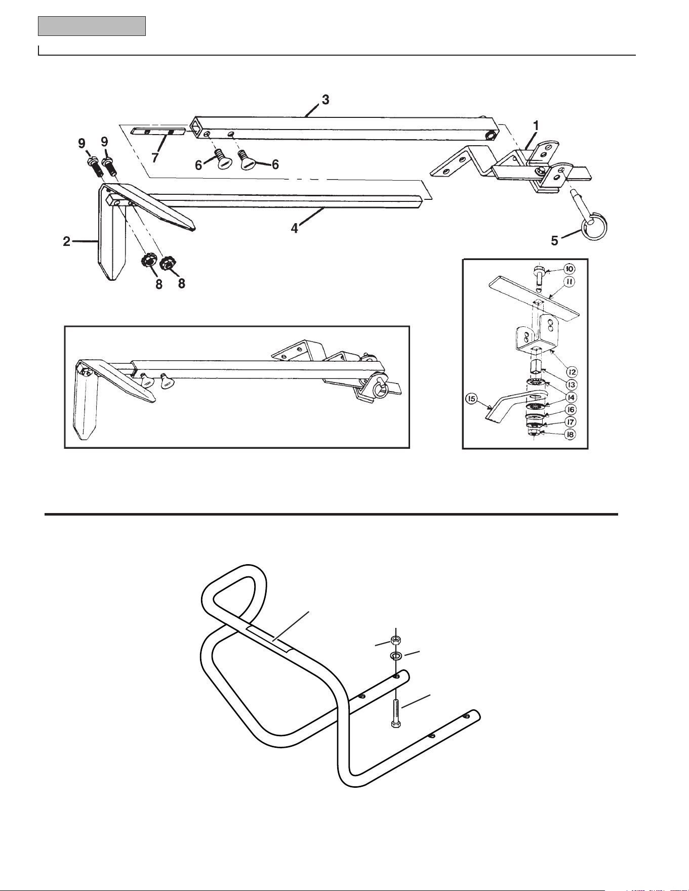
34 Parts List
Model 675B
ROW MARKER ATTACHMENT
ROW MARKER ATTACHMENT – OEM-290-257
(Complete – Attaches to Furrower Attachment)
MAIN SUPPORT/YOKE ASSEMBLY
PART # 1904522001
DETAIL A
19
20
23
22
21
BUMPER
OEM-290-254
(See Detail A)
BUMPER ATTACHMENT

Parts List 35
Model 675B
ROW MARKER ATTACHMENT & BUMPER ATTACHMENT
Row Marker Attachment (option) – OEM-290-254
1 1904522 Main Support & Yoke Assy–
complete. (Incl. Ref. No.'s
10,11,12,13,14,15,16,17 & 18).......... 1
2 GW-1594 Marker Blade–blade only ................... 1
3 1904524 Marker Arm–main arm ...................... 1
4 1904523 Marker Arm–extension arm with
stop pin ......................................... 1
5 GW-9347 Hitch Pin–(incl. in Hardware Pkg
GW-1837)...................................... 1
6 GW-9786 Thumbscrew–1/4-20 x 1/2, not
avail. sep. (see hardware pkg.
GW-1837)...................................... 2
7 GW-1596 Nut Bar–(incl. in hardware pkg
GW-1837)...................................... 1
8 GW-9828 Nut–hex, 10-24 w/attached start
washers, not avail. sep. (see
hardware pkg #1837) .................... 2
9 1100135 Screw–round hd.,10-24 x 1, not
avail. sep. (see hardware pkg
GW-1837)...................................... 2
--- GW-1837 Hardware Package–includes: one
GW-9347 hitch pin (Ref. 5), two
GW-9786 thumbscrews (Ref. 6),
one GW-1596 nut bar (Ref. 7),
two GW-9828 hex nuts (Ref. 8),
two 1100135 screws (Ref. 9) ........ 1
Row Marker Main Support & Yoke Assembly – Part #1904522001
10 1186349 Screw–hex flanged locking,
3/8-16 x 1-1/2* ............................. 1
11 GW-1593 Stop Bar ............................................ 1
12 GW-1592 Yoke .................................................. 1
13 GW-1591 Tube Key–square............................... 1
14 GW-1590 Washer–friction................................. 2
15 GW-1588 Main Support .................................... 1
16 GW-1589 Washer–square hole.......................... 1
17 GW-9925 Washer–disc spring .......................... 1
18 1186231 Nut–hex 3/8-16 ................................. 1
Bumper – OEM-290-254
19 1918749 Bumper ............................................. 1
20 777S30653 Decal - Caution.................................. 1
21 710-3073 Screw–hex hd., 5/16-18 x 2-1/4*,..... 4
22 736-0119 Lockwasher–5/16*,........................... 4
23 712-0267 Nut–hex, 5/16-18*, ........................... 4
--- 1918781 Hardware Kit: Incl. four each of
Refs. 21, 22 and 23 ....................... 1
Note: Common hardware listed above as “not available separately” can be found at
most hardware stores.
* Specify GRADE 5 if ordering part locally.
REF PART
No. No. DESCRIPTION QTY.
REF PART
No. No. DESCRIPTION QTY.

TROY-BILT TILLER LIFETIME LIMITED WARRANTY
WHAT PRODUCT All Troy-Bilt branded rear tine walk-behind tillers with gear drive transmissions.
IS COVERED This warranty begins on the date of purchase and is warranted by Troy-Bilt LLC for the life
of the tiller, to the original purchaser only.
WHAT IS COVERED Troy-Bilt LLC will, at its option, repair or replace any part found to be defective in material
BY THIS WARRANTY or workmanship without charge for parts and labor.
This limited lifetime warranty also applies to non-powered attachments and accessories. Powered
attachments and accessories are warranted separately by their manufacturers. Refer to the applicable
manufacturer’s warranty on these items for terms and conditions.
WHAT IS NOT This warranty does not apply to parts that have been damaged by accident, alteration,
COVERED BY THIS misuse, abuse, neglect, improper maintenance, vandalism, theft, fire, water, or damage
WARRANTY because of peril or other natural disaster.
The following items are not covered after the first year of this residential use limited warranty: belts,
batteries, bushings, seals, tines, tires, wheels, paint, appearance items, and similar items that are nor-
mally replaced through periodic maintenance.
Charges for pick-up, delivery, and service calls are not covered by this warranty.
Service completed by someone other than an authorized service dealer is not covered by this warranty.
Parts that are not genuine Troy-Bilt LLC service parts are not covered by this warranty.
The engine is warranted separately by the engine manufacturer. Refer to the engine manufacturer’s
warranty for terms and conditions.
LIMITED If used for commercial, institutional, industrial, rental, or demonstrator purposes, the
COMMERCIAL warranty on the tiller is limited in duration to 90 days from the date of purchase.
USE WARRANTY
This warranty does not apply to parts that have been damaged by accident, alteration, misuse, abuse,
neglect, improper maintenance, vandalism, theft, fire, water, or damage because of peril or other natural
disaster.
HOW TO OBTAIN Warranty service is available,
with proof of purchase, through your local authorized
SERVICE service dealer. To locate a dealer in your area, consult your Yellow Pages, or contact Troy-Bilt LLC at
P.O. Box 361131, Cleveland, Ohio 44136-0019, 1-866-840-6483, or log on to our Web site at
www.troybilt.com.
The provisions set forth in this warranty provide the sole and exclusive remedy arising from the sale. Troy-Bilt LLC shall
not be liable for any incidental or consequential damage or expense of any kind, including but not limited to cost of
equipment rental, loss of profits, or costs of hiring services to perform tasks normally performed by the equipment.
Any implied warranties, including any implied warranty of merchantability or fitness for a particular purpose, shall be limited in
duration to the period of ownership by the original purchaser (and a maximum of 90 days from the date of sale if the tiller is
purchased for commercial or other non-residential use).
Some states do not allow the exclusion or limitation of incidental or consequential damages, or limitations on how long an
implied warranty lasts, so the above exclusions or limitations may not apply to you.
This limited warranty gives you specific legal rights, and you may also have other rights which vary from state to state.
For customer assistance, contact your nearest authorized dealer, or contact us at:
TROY-BILT LLC, P.O. Box 361131, Cleveland, Ohio 44136-0019, 1-866-840-6483