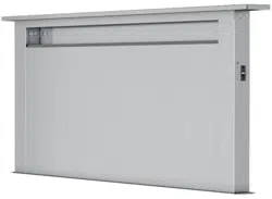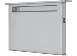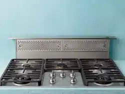
Models: DLI-E30ASX, DLI-E36ASX
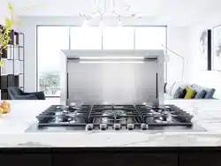
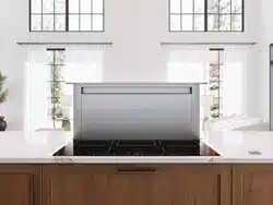
Downdraft Hood
For use with these blowers
(purchase blowers separately):
Model DBI-600A - Internal
Models CBE-1000 - External
Models PBN-1000A - In-Line
READ AND SAVE THESE INSTRUCTIONS
Register your product online at: www.zephyronline.com
Français p. 35
Español p. 69
APR19.0101

2
Table of Contents
Safety Information .................................................................................................................................................................................. 3
Contents .................................................................................................................................................................................................. 4
Specifications ......................................................................................................................................................................................... 4
Tools Needed ........................................................................................................................................................................................... 4
Planning
Before You Begin ............................................................................................................................................................................... 5
Taking Measurements........................................................................................................................................................................ 5
Ducting Configurations ...................................................................................................................................................................... 5
Cabinet Cutouts ................................................................................................................................................................................. 10
Preparing the Downdraft
Side or Rear Ducting .......................................................................................................................................................................... 12
Front Ducting ..................................................................................................................................................................................... 12
Electrical Panel in Remote Location ................................................................................................................................................... 13
Final Assembly ................................................................................................................................................................................... 13
Installation
Cutting Countertop Opening ............................................................................................................................................................... 14
Install Housing into Cabinet ................................................................................................................................................................ 15
Install Finishing Trim .......................................................................................................................................................................... 16
Installing Ductwork ............................................................................................................................................................................ 16
Electrical Wiring Installation
Internal Blower Only .......................................................................................................................................................................... 17
Exterior or In-Line Blower Only .......................................................................................................................................................... 18
Appliance Installation/Operation ........................................................................................................................................................... 19
Use and Care ........................................................................................................................................................................................... 20
Optional Accessories .............................................................................................................................................................................. 21
Blower Duct Routing Configurations A - H ............................................................................................................................................ 23
Wiring Diagram ....................................................................................................................................................................................... 31
Dimensional Drawing ............................................................................................................................................................................. 32
Warranty ................................................................................................................................................................................................. 33
3
Safety Information
WARNING
TO REDUCE THE RISK OF FIRE, ELECTRIC SHOCK, OR
INJURY TO PERSONS, OBSERVE THE FOLLOWING:
1. Use this unit only in the manner intended by the manufacturer.
If you have questions, contact the manufacturer at the address
or telephone number on the back page.
2. Before servicing or cleaning unit, switch power off at
service panel and lock the service disconnecting means to
prevent power from being switched on accidentally. When the
service disconnecting means cannot be locked, securely fasten
a prominent warning device, such as a tag, to the service
panel.
3. Installation work and electrical wiring must be done by a
qualified person(s) in accordance with all applicable codes and
standards, including fire-rated construction codes and
standards.
4. Sufficient air is needed for proper combustion and exhausting
of gases through the flue (chimney) of fuel burning equipment
to prevent backdrafting. Follow the heating equipment
manufacturer’s guideline and safety standards such as those
published by the National Fire Protection Association (NFPA),
and the American Society for Heating, Refrigeration and Air
Conditioning Engineers (ASHRAE), and the local code
authorities.
5. When cutting or drilling into wall or ceiling, do not damage
electrical wiring and other hidden utilities.
6. Ducted fans must always be vented to the outdoors.
7. To reduce the risk of fire, use only metal ductwork.
8. Do not install this product with the activating switch directly
behind a burner or element. Minimum distance between the
switch and the edge of the burner should be 4 inches.
9. Loose-fitting or hanging clothing should never be worn when
operating this appliance. They may be ignited by burners/
elements on cooktop.
10. Children should not be left alone or unattended in the area
where this appliance is in use.
11. This unit must be grounded.
TO REDUCE THE RISK OF A RANGE TOP GREASE FIRE:
a) Never leave surface units unattended at high settings. Boil
overs cause smoking and greasy spillovers that may ignite.
Heat oils slowly on low or medium settings.
b) Always turn hood ON when cooking at high heat or when
cooking flaming foods.
c) Clean ventilating fans frequently. Grease should not be allowed
to accumulate on fan or filter.
d) Use proper pan size. Always use cookware appropriate for the
size of the surface element.
WARNING
TO REDUCE THE RISK OF INJURY TO PERSONS IN THE
EVENT OF A RANGE TOP GREASE FIRE, OBSERVE THE
FOLLOWING:
1. SMOTHER FLAMES with a close-fitting lid, cookie sheet, or
metal tray, then turn off the burner. BE CAREFUL TO PREVENT
BURNS. If the flames do not go out immediately, EVACUATE AND
CALL THE FIRE DEPARTMENT.
2. NEVER PICK UP A FLAMING PAN - You may be burned.
3. DO NOT USE WATER, including wet dishcloths or towels -
a violent steam explosion will result.
4. Use an extinguisher ONLY if:
A. You know you have a Class ABC extinguisher, and you
already know how to operate it.
B. The fire is small and contained in the area where it started.
C. The fire department is being called.
D. You can fight the fire with your back to an exit. Based on
“Kitchen Fire Safety Tips” published by NFPA.
CAUTION
1. For indoor use only.
2. For general ventilating use only. Do not use to exhaust
hazardous or explosive materials and vapors.
3. To avoid motor bearing damage and noisy and/or unbalanced
impellers, keep drywall spray, construction dust, etc. off
power unit.
4. Clean filters and grease-laden surfaces frequently.
5. Do not repair or replace any part of this appliance unless
specifically recommended in this manual. All other servicing
should be done by a qualified technician.
6. Please read specification label on product for further
information and requirements.
7. To reduce the risk of fire and electric shock, install this
downdraft only with blower models shown below. Other blower
models cannot be substituted. (Blowers sold separately).
Internal Blower Model DBI-600A, Exterior Blower Model CBE-
1000, In-Line Blower Model PBN-1000A.
INSTALLER: Save this manual for Electrical Inspector
and Homeowner to use.
4
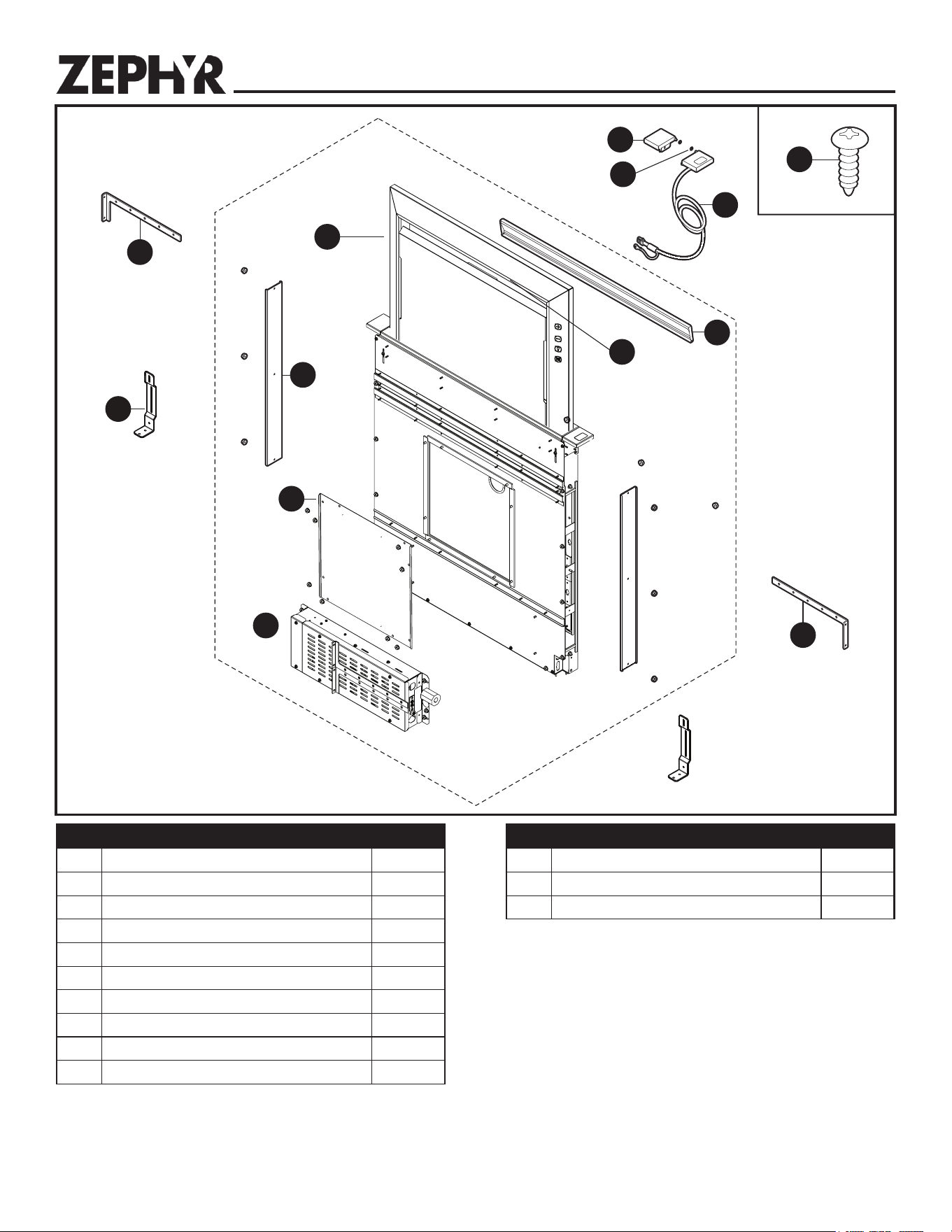
Contents
G
H
I
C
D
B
A
BB
L
x4
x8
J
ELECTRICAL
SPECIFICATIONS
Model DBI-600A - Internal
120 VAC • 60 Hz • 3.0 A
Models CBE-1000 - Exterior
Models PBN-1000A - In-Line
120 VAC • 60 Hz • 6.0 A (max.)
M
C1
N
E
x2
Tools Needed
Measuring tape, pencil, Phillips screwdriver #2, nut drivers (11/32", 3/8", 7/16"), box-end wrench, saw, spirit-level, tin snips, work gloves,
and aluminum tape. (DO NOT use insulating tape.)
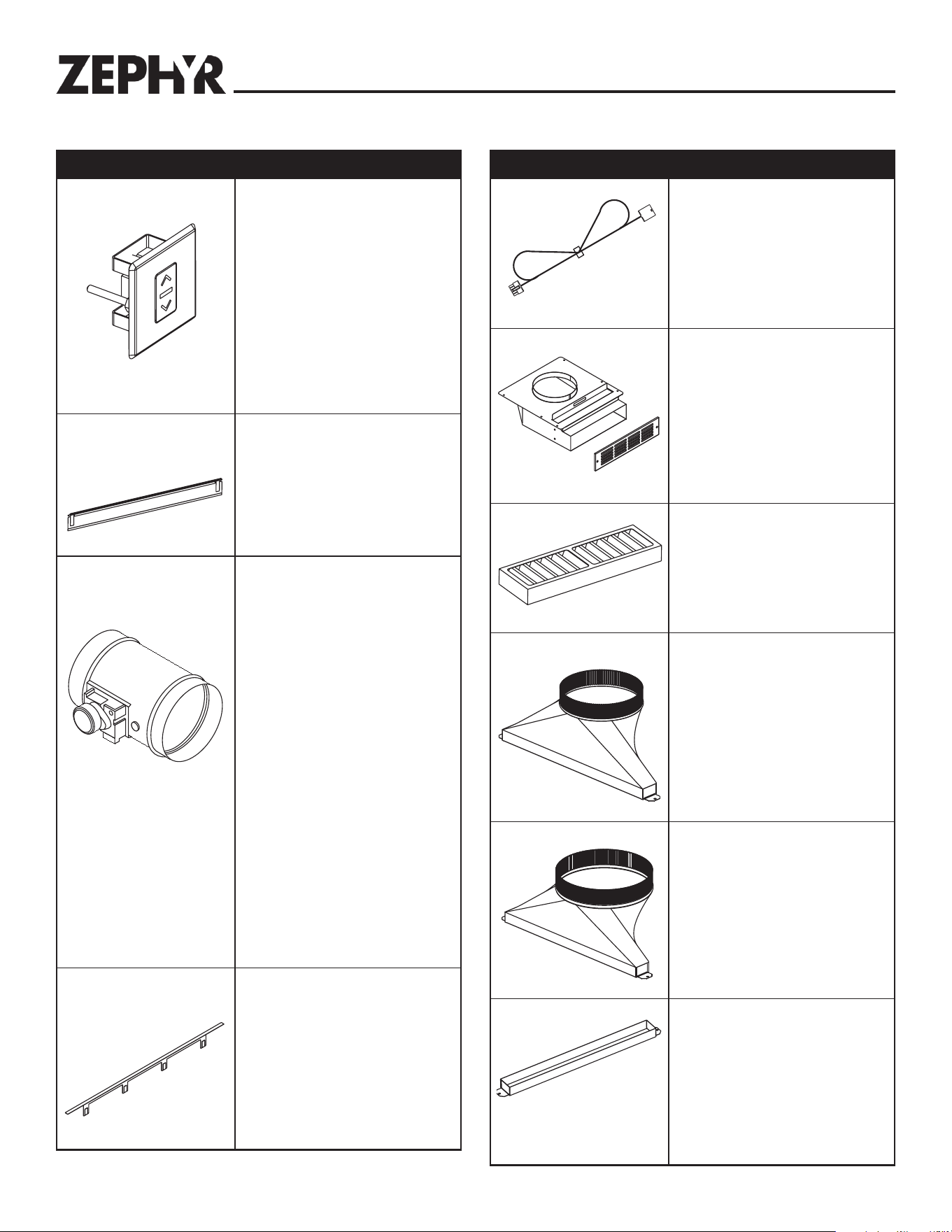
Part Description
Quantity
A Upper support bracket (left) 1
B Downdraft ventilator housing 1
C End cap trim (left) 1
C1 End cap trim retaining washer 2
D End cap trim–up button (right) 1
E Support Leg 2
G Discharge cover 4
H Front panel cover 1
I Electrical panel 1
J Upper support bracket (right) 1
Part Description
Quantity
M Flip door 1
N LED light strip 1
BB #10 x .50 Phillips round head screw 8
5
Planning
Due to its flexible design, this downdraft system can be used to
exhaust airborne contaminants when cooking with a variety of gas
or electric cooking appliances - including cooktops, rangetops,
slide-in ranges and free-standing ranges.
It can be mounted in island, peninsula, or conventional wall
locations. The blower (purchase separately) and electrical panel
can be mounted to the downdraft unit, inside the cabinet, or in a
convenient remote location.
This unit can be easily installed following these basic steps:
• Cut out the countertop opening.
• Mount the unit in the cabinet.
• Install the blower and electrical panel.
• Connect the ductwork and electrical.
• Install the trim.
• Install the cooking appliance.
Note: the high level of air flow of this appliance may affect the
gas flame on some types of gas cooktops. This is NORMAL and
will cause no harm, but can be corrected by lowering the speed
of the blower.
Gas Cooktop Seal Kit is recommended for use with all gas
cooktops. The kit creates a seal between the cooktop and the
lower cabinet. Includes trim bracket and trim seal. See Optional
Accessories section.
Taking Measurements
• Refer to the cooktop installation instructions for dimensions
of cooktop, countertop cut-out, and cabinet requirements.
However, it is recommended that oversized cabinets be used
for easier installation. Custom island designs need to account
for deeper cabinets - especially when installed with a range in
front of the downdraft or when mounting the blower behind the
downdraft. You must also plan for an access door.
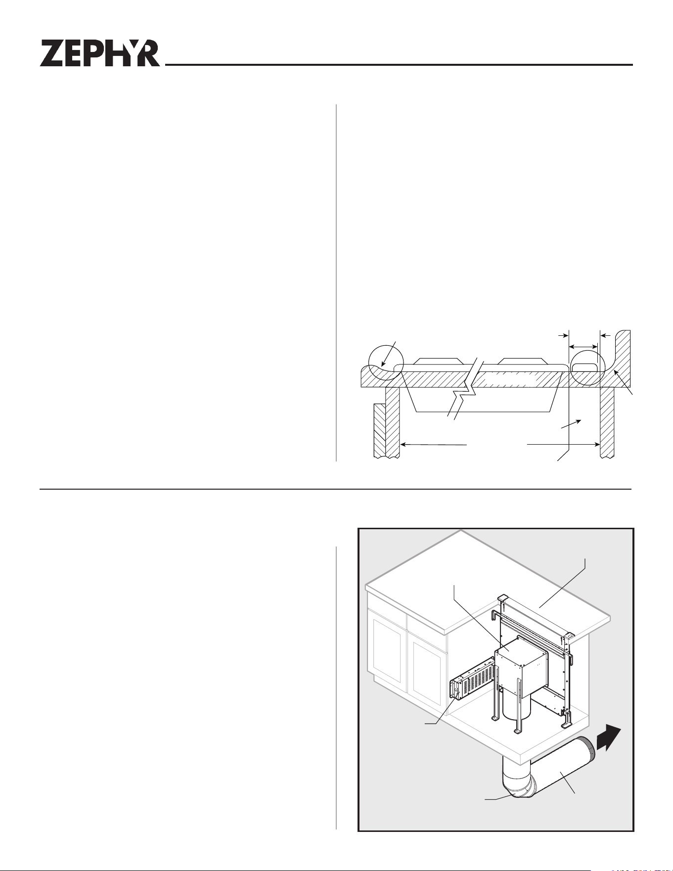
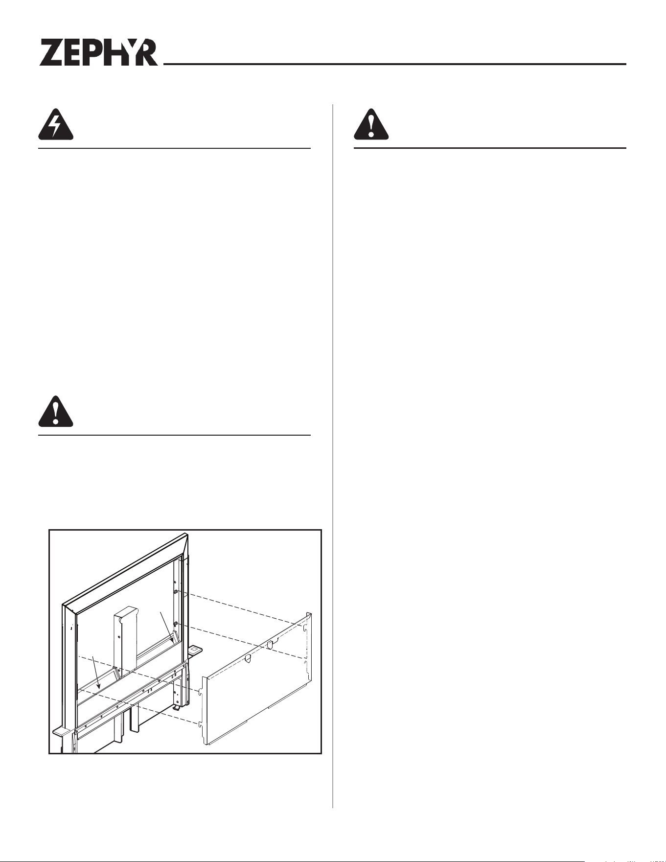
• Cooktop depth can vary greatly from one to another. This
may cause the fit of these two appliances to be rather tight.
Pay special attention to the areas of potential interference
highlighted above. A countertop with (A) a raised lip and/or (B)
a backsplash may not allow enough flat countertop for a proper
installation. Note that 2-3/4" of flat countertop is required
behind cooktop and that 2-1/2" is necessary between the back
edge of the cooktop and the inside of cabinet back.
2-7/8"
A
B
2-3/4"
Downdraft
Cooktop
Front to Back
Inside Cabinet Depth
CountertopCountertop
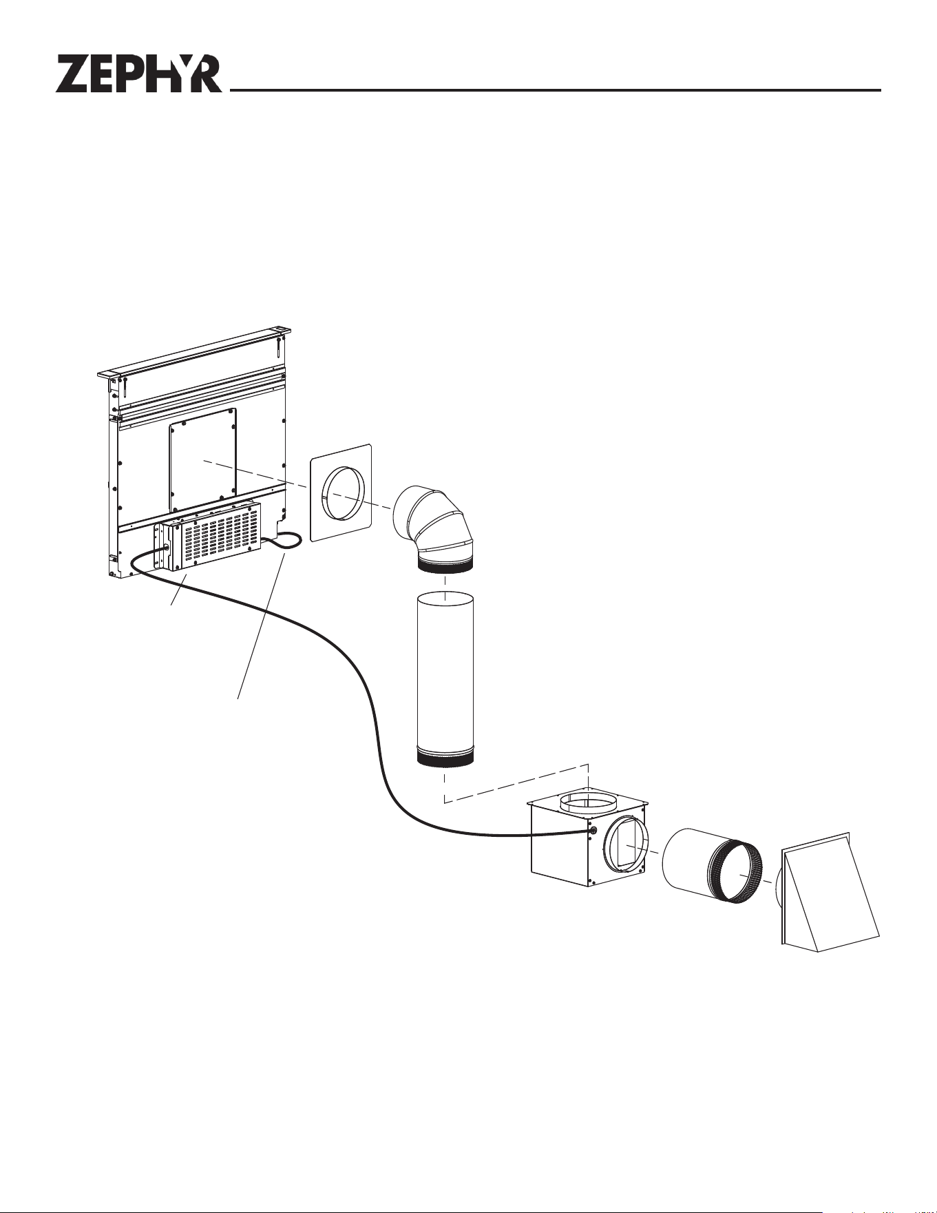
Before You Begin
Downdraft
8" Round Elbow
DBI-600A Blower
8
"
Straight Duct
Electrical Panel
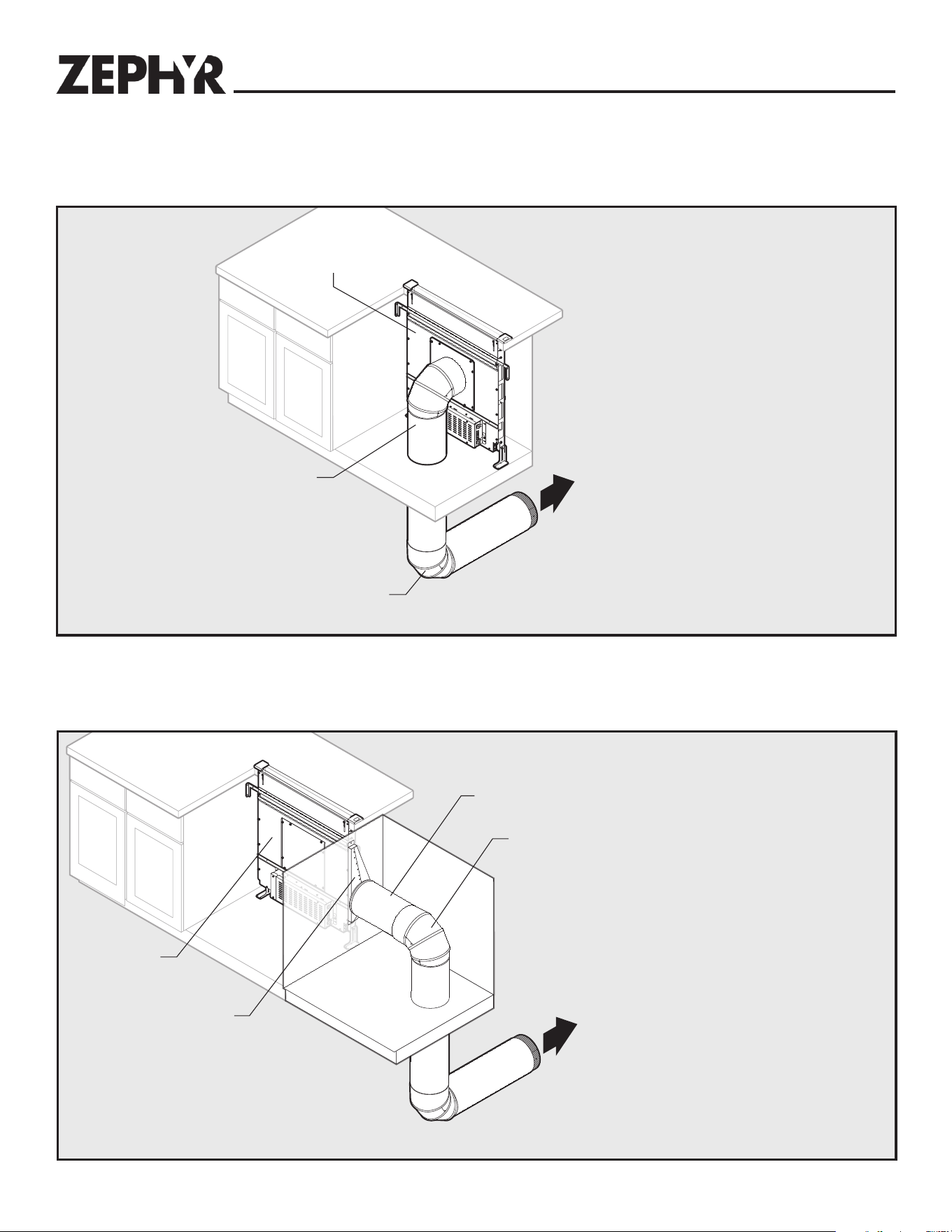
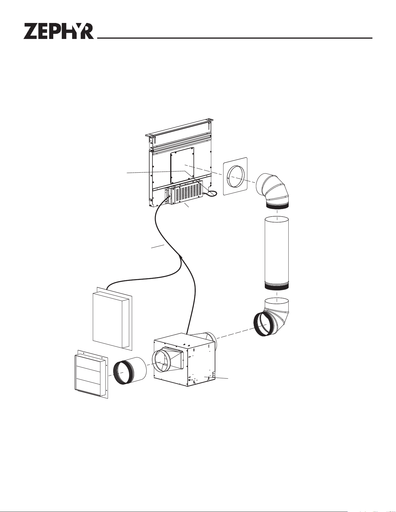
Ducting Configurations
Front Exhaust with Internal Blower
• The downdraft blower system is designed for use with 8" round
ductwork using a DBI-600A blower or 10" round ductwork using
a remote blower. (Purchase blowers separately.)
• For best performance: Choose the ducting option which allows
the shortest length of ductwork and a minimum number of
elbows and transitions. Check location of floor joists, wall studs,
electrical wiring or plumbing for possible interference.
6
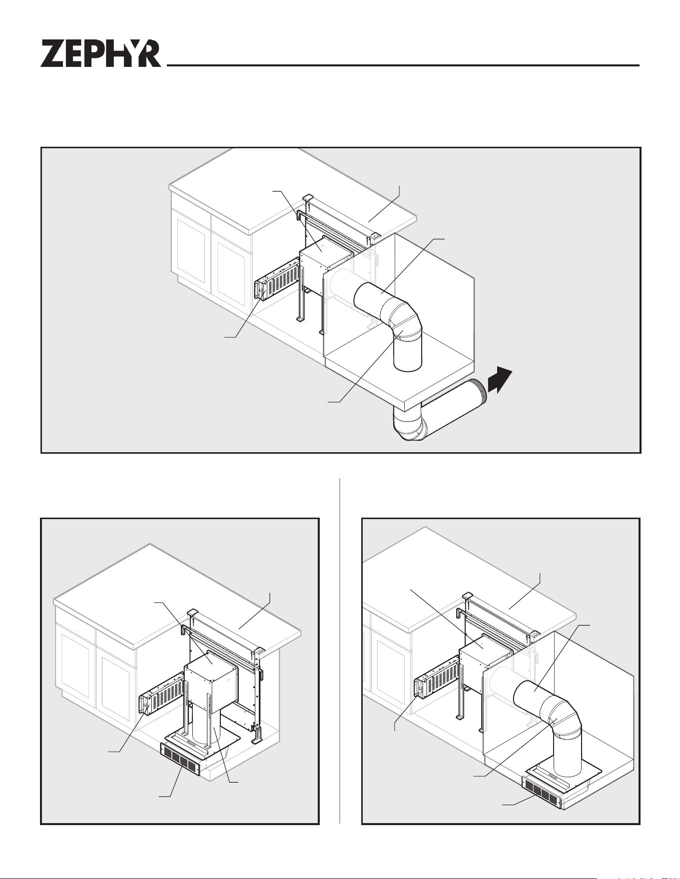
Ducting Configurations (continued)
Planning
Front Exhaust with DBI-600A Blower (through cabinet)
Electrical Panel
Downdraft
DBI-600A Blower
8
"
Straight Duct
8
"
Round Elbow
Downdraft
Electrical Panel
ZRC-00LF (Recirculating Kit)
DBI-600A Blower
8
"
Straight Duct
Front Exhaust with DBI-600A Blower and
Recirculating Kit
Front Exhaust with DBI-600A Blower (through
cabinet) and Recirculating Kit
Electrical Panel
Downdraft
DBI-600A Blower
8
"
Straight
Duct
8
"
Round Elbow
ZRC-00LF (Recirculating Kit)
Refer to ZRC-00LF manual for further recirculating kit installation
instructions .
7
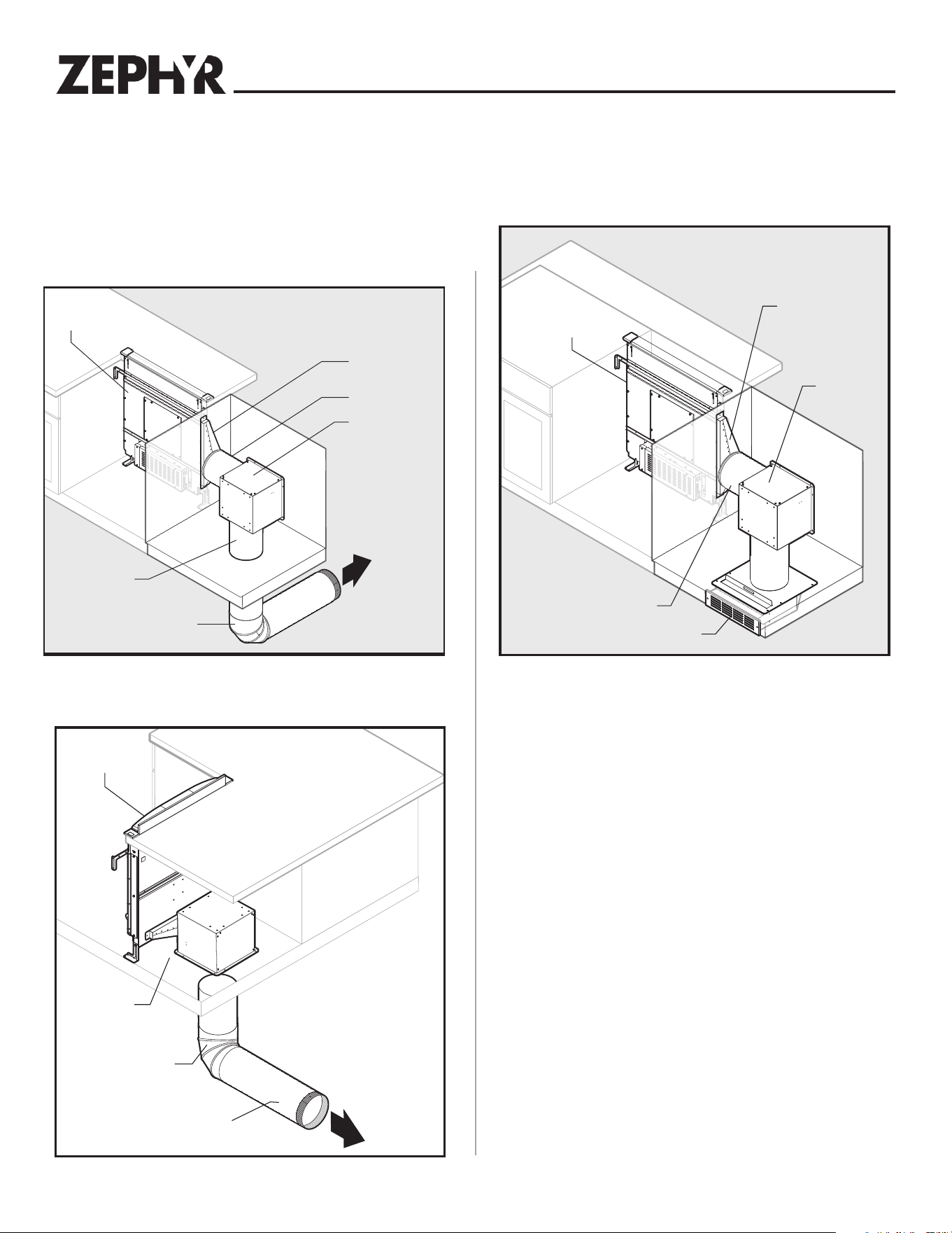
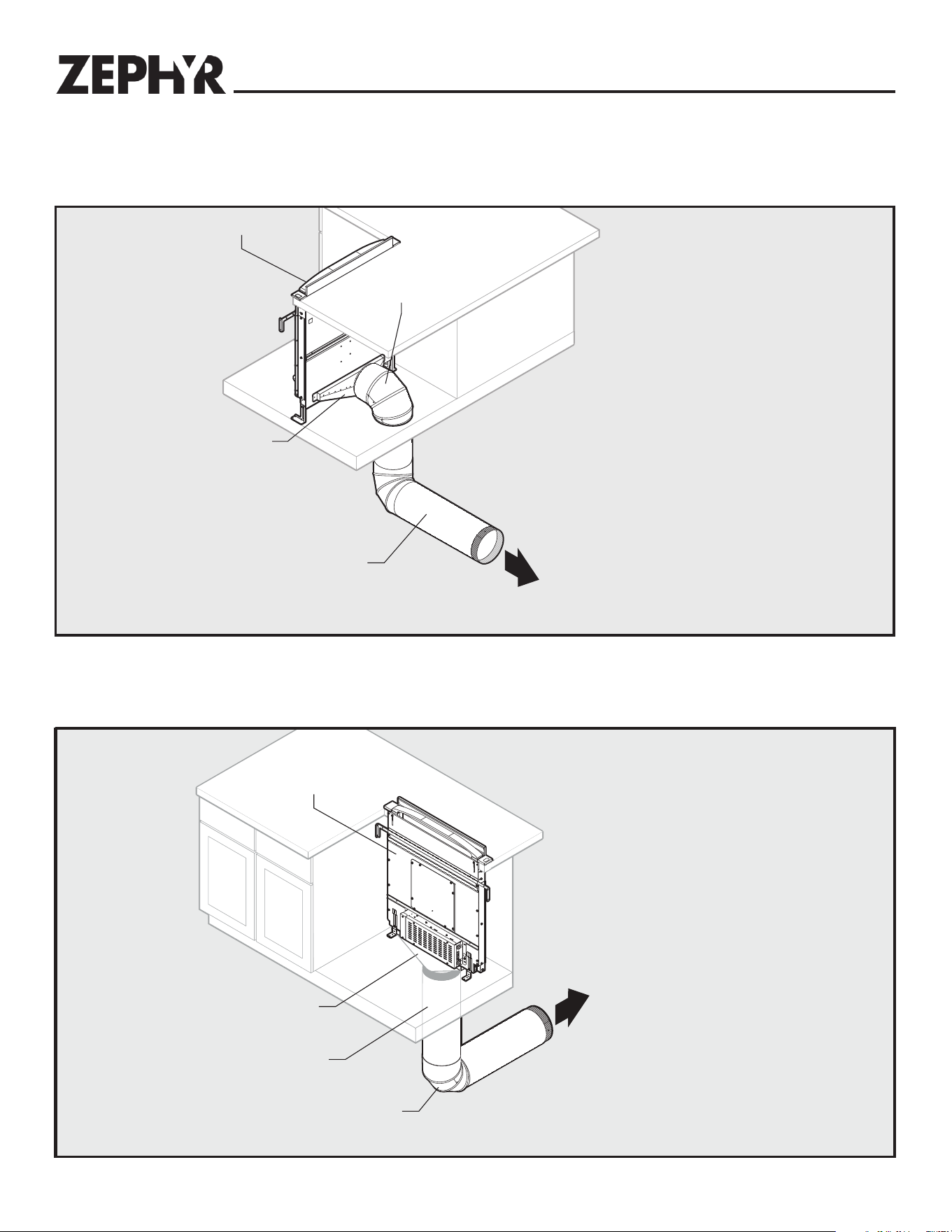
Planning
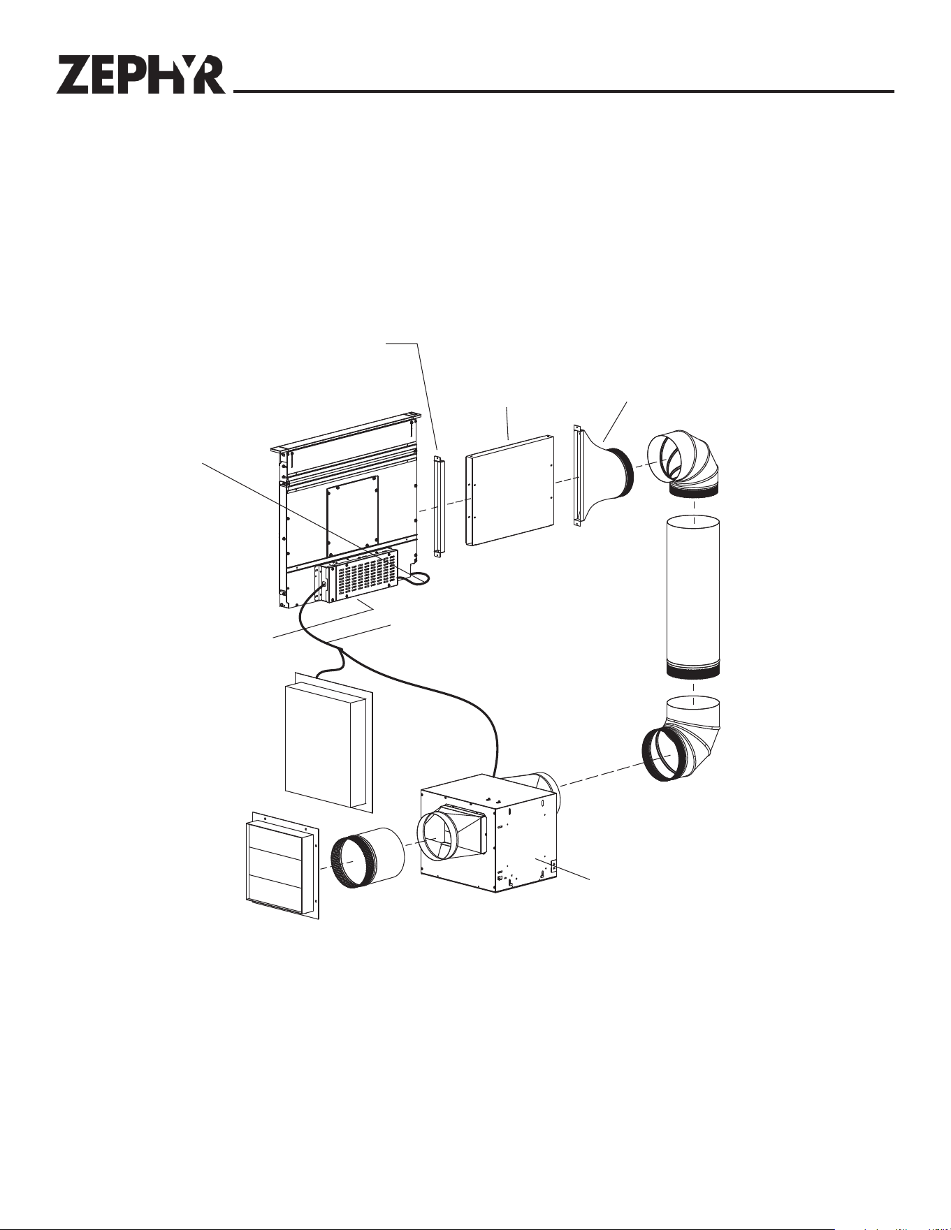
Ducting Configurations (continued)
Side Exhaust with DBI-600A Blower
Downdraft
1-7/8" to 8"
Round Transition
8" Round Elbow
DBI-600A Blower
8
"
Straight Duct
8
"
Straight Duct
Downdraft
1-7/8" to 8"
Round Transition
DBI-600A
Blower
8" Straight Duct
ZRC-00LF Recirculating Kit
Downdraft
8"
Round Elbow
8
"
Straight Duct
1-7/8" to 8"
Round Transition
Side Exhaust with DBI-600A Blower and
Recirculating Kit
Rear Exhaust with DBI-600A Blower
Refer to ZRC-00LF manaul for further recirculating kit installation
instructions .
8
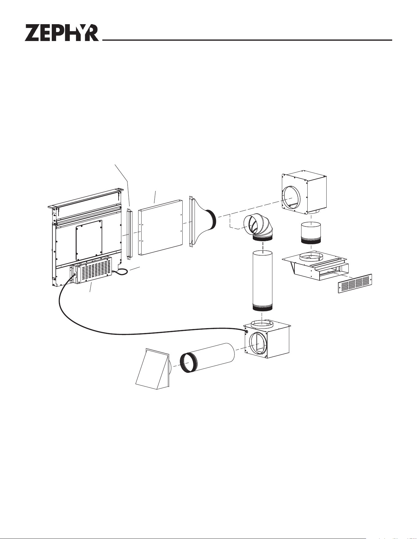
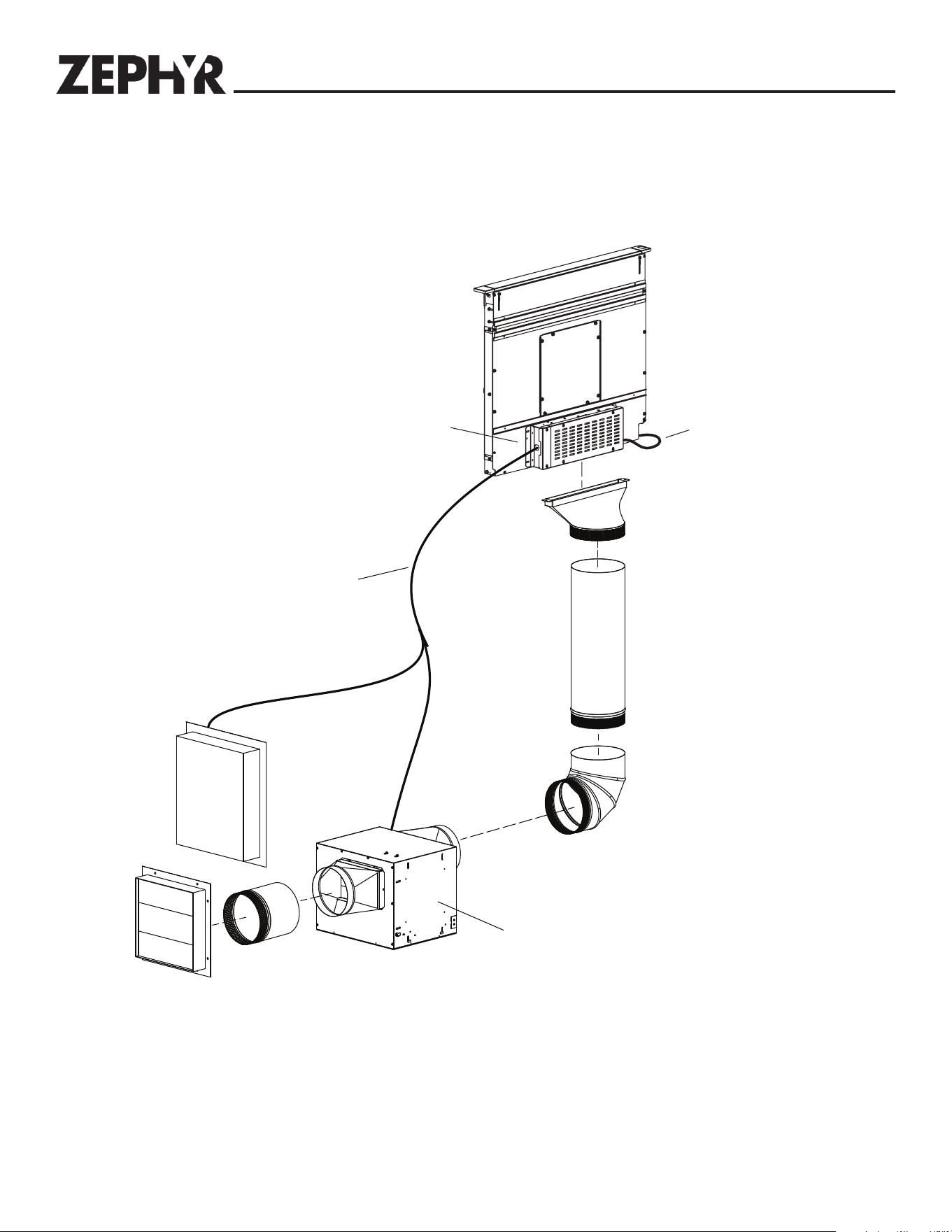
Planning
Downdraft
10
"
Round Elbow
10"
Straight Duct
* To one of the following:
Model CBE-1000 External Blower
• Model PBN-1000A In-line Blower
Note: External or in-line blowers require 10" ducting.
*
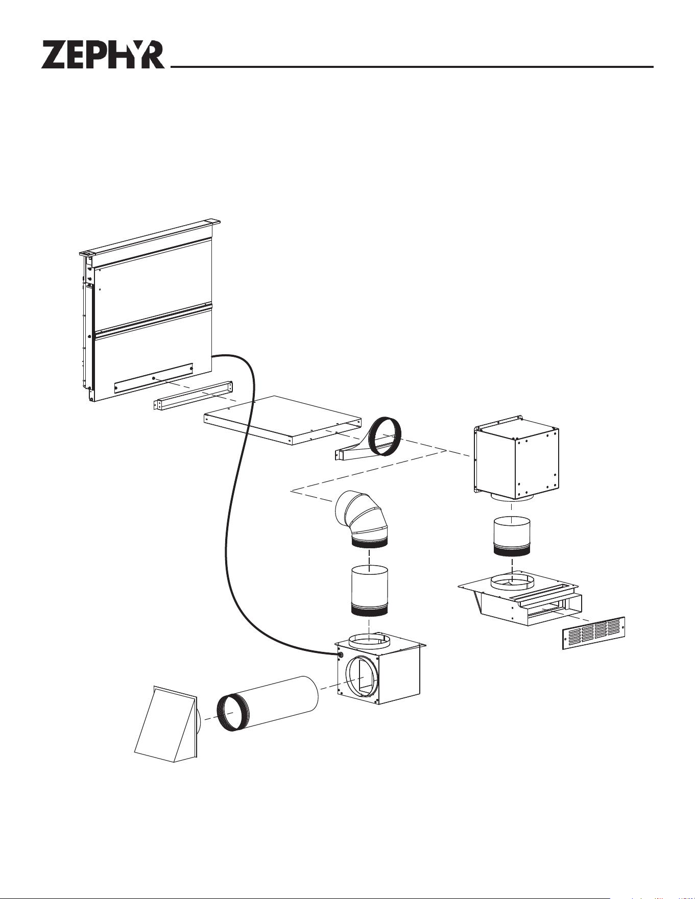
Downdraft
1-7/8" to
10" Round Transition
10"
Round Elbow
10"
Straight Duct
* To one of the following:
Model CBE-1000 External Blower
• Model PBN-1000A In-line Blower
Note: External or in-line blowers require 10" ducting.
*
Side Exhaust with Remote Blower
Ducting Configurations (continued)
Front Exhaust with Remote Blower
9
Planning
Downdraft
1-7/8" to 10"
Round Transition
10" Round Elbow
10"
Straight Duct
*
* To one of the following:
Model CBE-1000 External Blower
• Model PBN-1000A In-line Blower
Note: External or in-line blowers require 10" ducting.
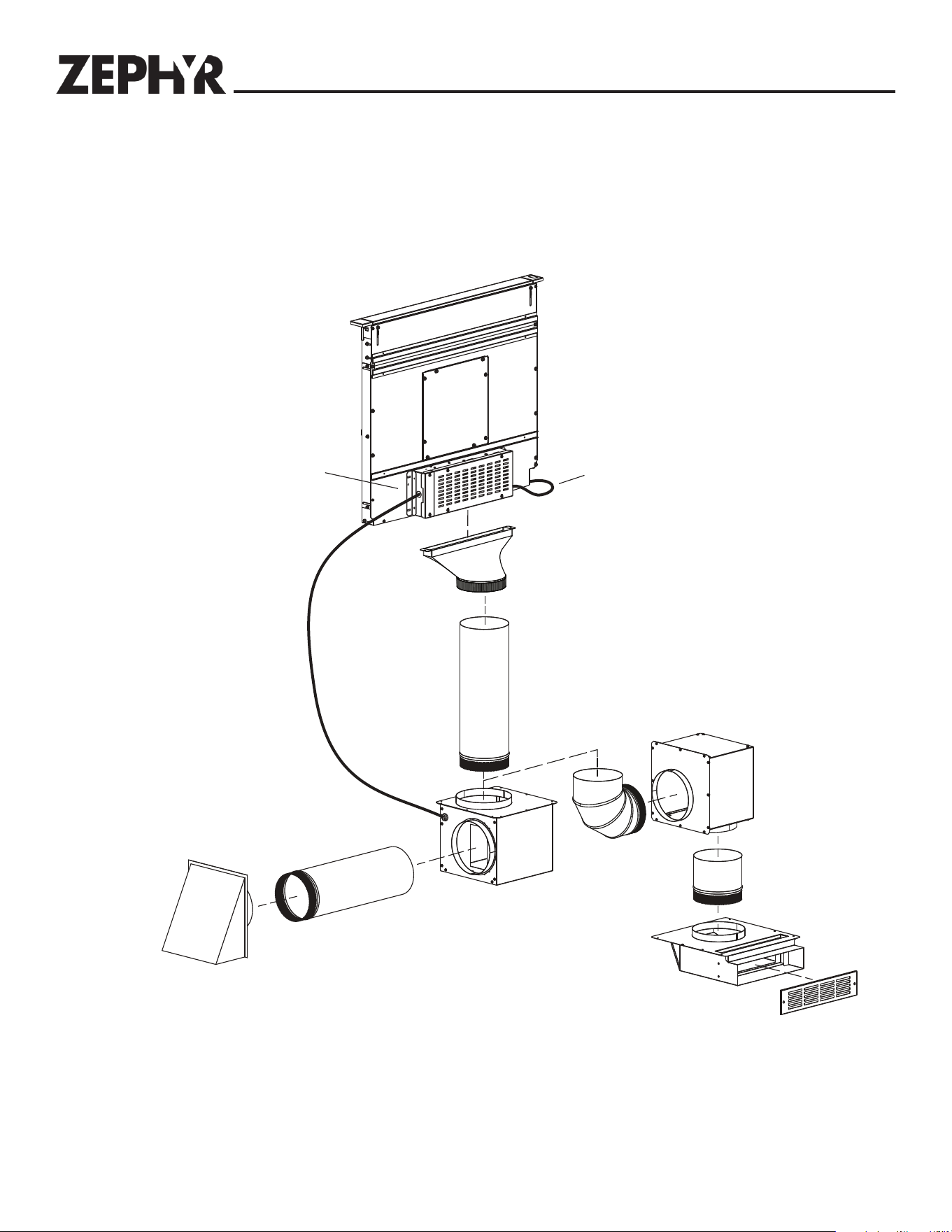
Downdraft
8
"
or 10
"
Round Elbow
* To one of the following:
• Model DBI-600A Blower
• Model PBN-1000A In-Line Blower
Note:: DBI-600A blower requires 8" ducting. External or in-line blowers require 10" ducting.
*
8
" or 10"
Straight Duct
1-7/8" to 8" or
10" Round Transition
• Model CBE-1000 External Blower
Below Exhaust with Remote Blower
Ducting Configurations (continued)
Rear Exhaust with Remote Blower
10
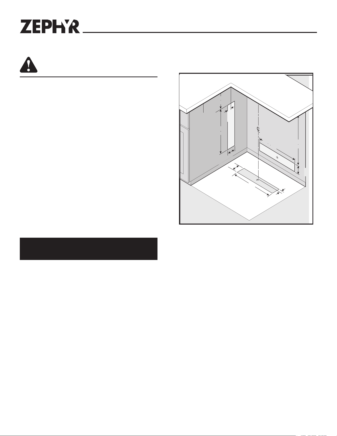
Planning
CAUTION
BEFORE CUTTING HOLE IN CABINET FOR DUCTWORK,
check for interference with floor joists, wall studs,
electrical wiring, or plumbing.
Use the dimensions in illustrations to help plan how and where to
provide duct access through your cabinet. Generally, 1-7/8" x 19"
rectangular duct will be used through left, right, below and back of
cabinet - while 8" round duct will be used through cabinet floor
using DBI-600A blower.
For left, right, below or rear exhaust: Allow at least 18" for transi-
tion and elbow or blower.
For left / right exhaust: a 30" deep cabinet is recommended to align
properly with DBI-600A blower. DBI-600A blower can be mounted
to rear cabinet wall or to a platform / frame (not provided) on the
base of the cabinet floor. (See DBI-600A blower instructions).
Note: DBI-600A blower can only attach to the front of the down-
draft.
Cabinet depths of 24" to 30" are required - depending on the
type of cooking appliance.
If using a Recirculating Kit, see “Plan the installation”
section of the installation instructions packaged with the
kit.
Cabinet Cutouts
4"
(10.2 cm)
5-7/8"
(14.9 cm)
5-7/8"
(14.9 cm)
21"
(53.3 cm)
21"
(53.3 cm)
Appliance
Cutout
2"
(5.1 cm)
1-1/8"
(2.9 cm)
1-1/8"
(2.9 cm)
4"
(10.2 cm)
4"
(10.2 cm)
21"
(53.3 cm)
21"
(53.3 cm)
21"
(53.3 cm)
21"
(53.3 cm)
24-3/4"
(62.9 cm)
24-3/4"
(62.9 cm)
4"
(10.2 cm)
Below, Side or Rear Ducting Cutouts
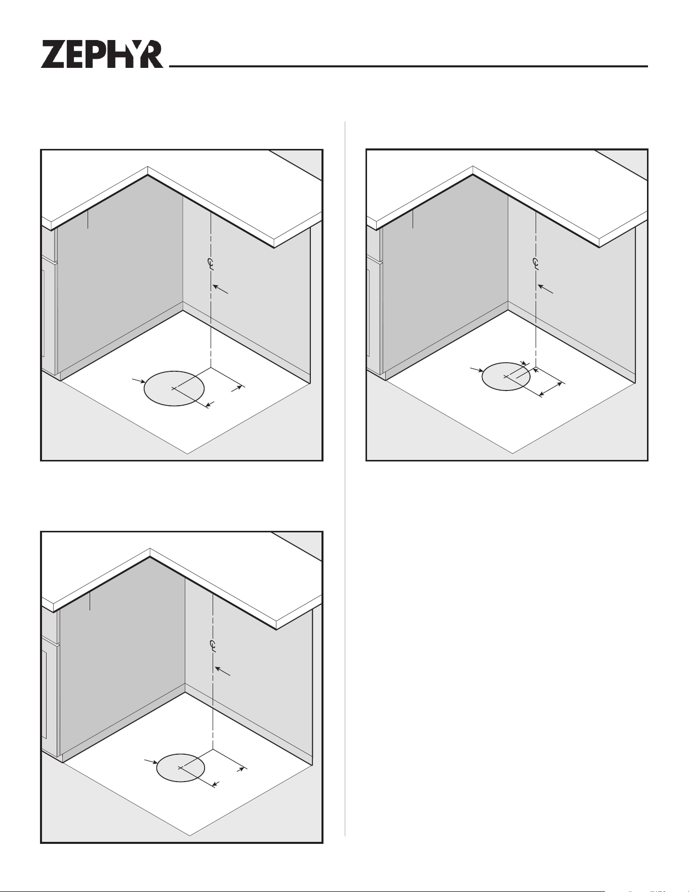
11
DBI-600A Blower Ducting Cutout10" External or In-line Blower Ducting Cutout
7-5/8"
(14.3 cm)
7-5/8"
(14.3 cm)
Ø8"
(20.3 cm)
Appliance
Cutout
Center line of downdraft
5-5/8"
(14.3 cm)
5-5/8"
(14.3 cm)
1-1/2"
(3.8 cm)
Ø8"
(20.3 cm)
Appliance
Cutout
Center line of downdraft
8-5/8"
(14.3 cm)
8-5/8"
(14.3 cm)
Ø10"
(25.4 cm)
Appliance
Cutout
Center line of downdraft
Planning
Cabinet Cutouts (continued)
Dimensions based off of - 10" round elbow
Dimensions based off of - 8" round elbow
DBI-600A Blower Ducting - Remote Location
Cutout
12
Install 8" or 10" remote discharge plate to downdraft (B).
(Remote discharge plate sold separately)
Install 1-7/8" to 8" or 10" round transition to downdraft (B).
(Rectangular to round transitions sold separately)
Install a transition and rectangular ductwork to downdraft (B).
(Rectangular ductwork sold separately)
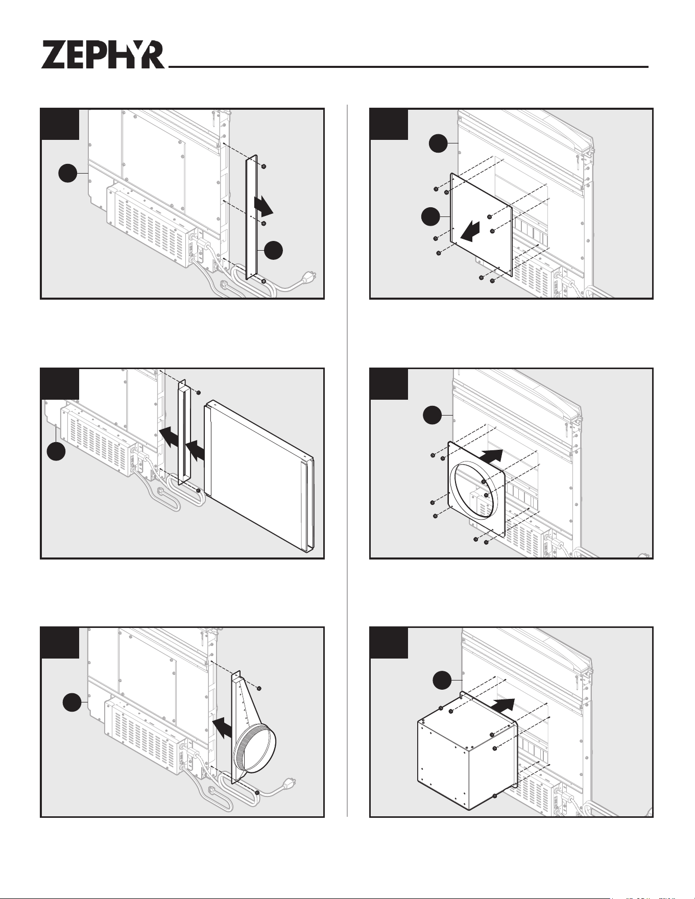
Remove a discharge cover (G) from sides or rear of downdraft (B).
Note: Only remove one cover.
Remove front panel cover (H) from downdraft (B).
Side or Rear Ducting
Preparing the Downdraft
Front Ducting
Install the DBI-600A blower to downdraft (B).
Note: DBI-600A blower can be installed with duct to left, right or downward.
1
B
G
1
B
H
2a
B
1
2
2a
B
1
2b
B
2b
B
13
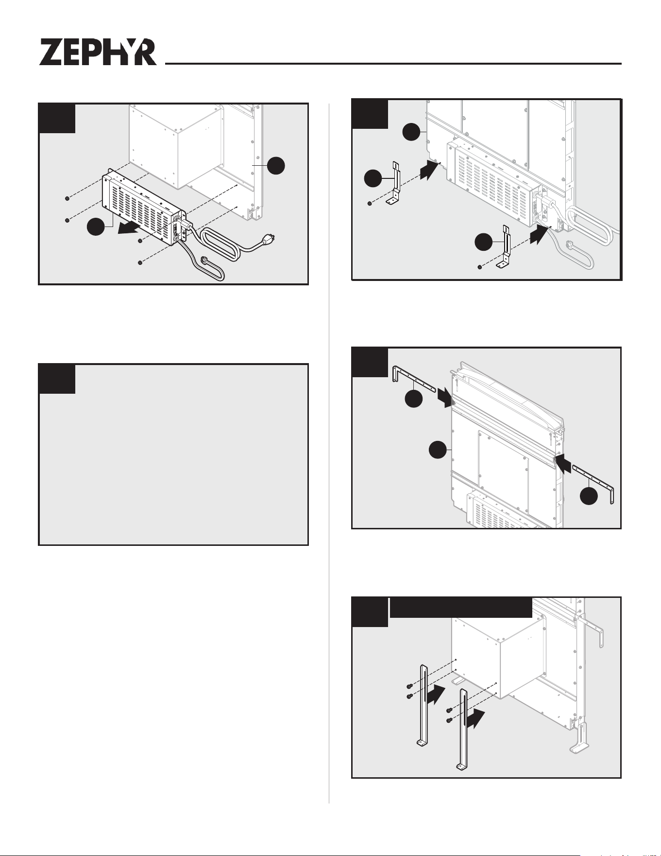
Preparing the Downdraft
If using DBI-600A blower, attach blower support legs with supplied
screws.
Slide upper support brackets (A,J) into side channels of downdraft (B).
Final Assembly
Attach previously removed lower support legs (E) to downdraft (B) using one
nut for each leg.
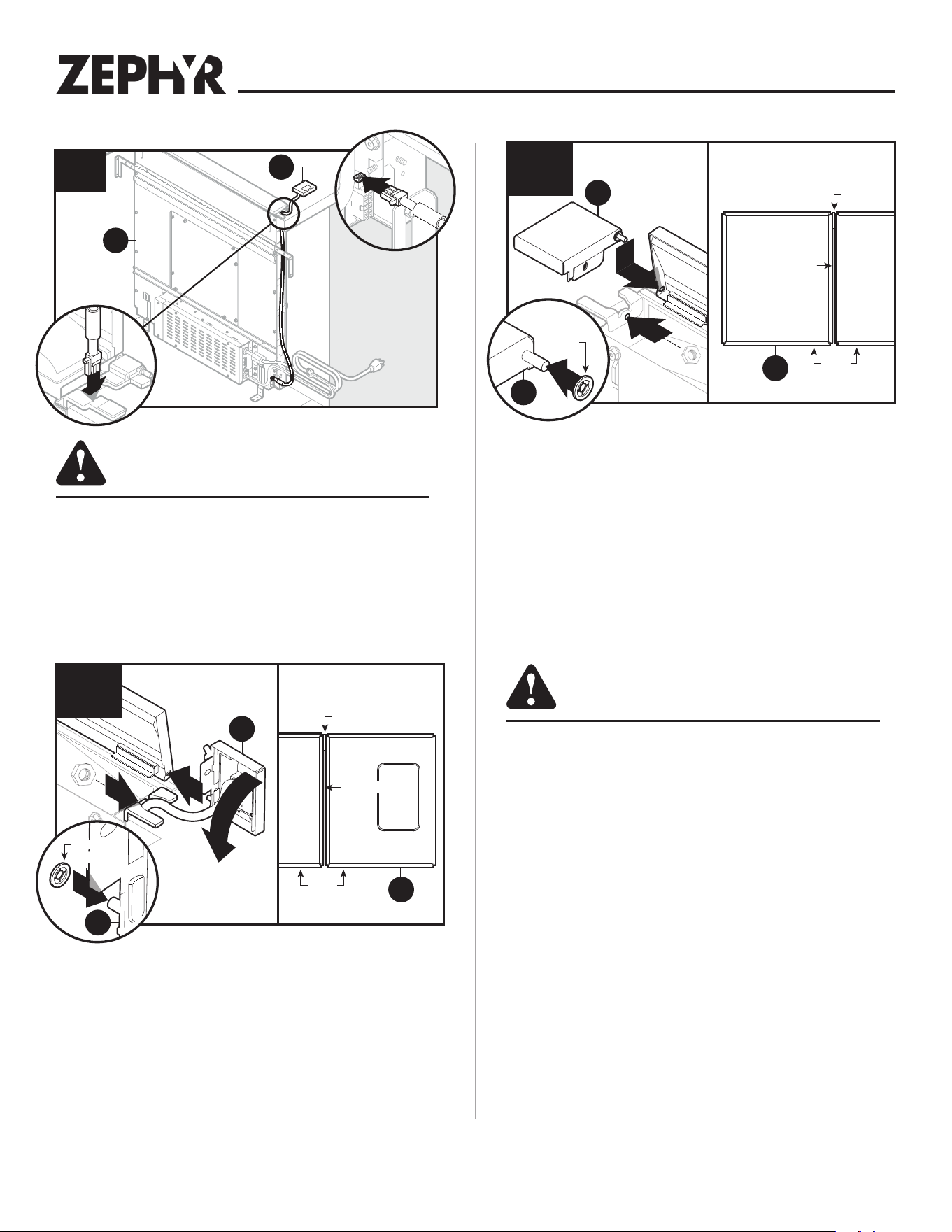
Electrical Panel in Remote Location
Remove electrical panel (I) from downdraft (B). Electrical panel connector
cable legth is 2 feet. Optional 5 foot cable extension available.
Note: Option for most installations. Required for DBI-600A blower installa-
tions when discharge is down.
1
B
I
2
Install electrical panel
in remote location.
3
3
B
E
E
4
B
A
J
5
DBI-600A Blower Only
14
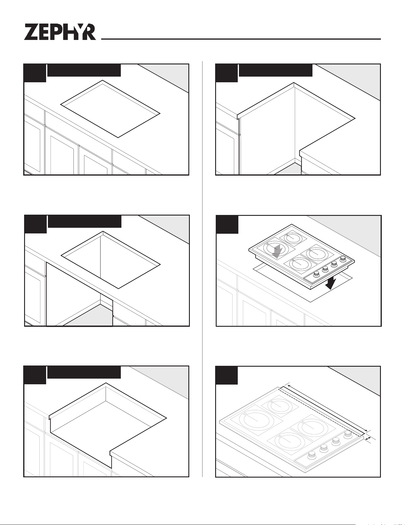
Center template against the back flange and mark downdraft opening.
A = 1-7/8" B = 27-1/4" DLI-E30ASX, 33-1/4" DLI-E36ASX
Place appliance.
Note: Cook top shown.
Cutting Counter Top Opening
Installation
6a
Cooktop
6d
Range
6b
Cooktop with Oven
6c
Rangetop
7
8
A
B
Gass Cooktop seal kit is recommended if installing a gas cooktop . See
Optional Accessory page for more information.
Gas Cooktop seal kit is recommended if installing a gas cooktop. See
Optional Accessory page for more information.
Range trim kit may be required. See Optional Accessory page for more
information.
15
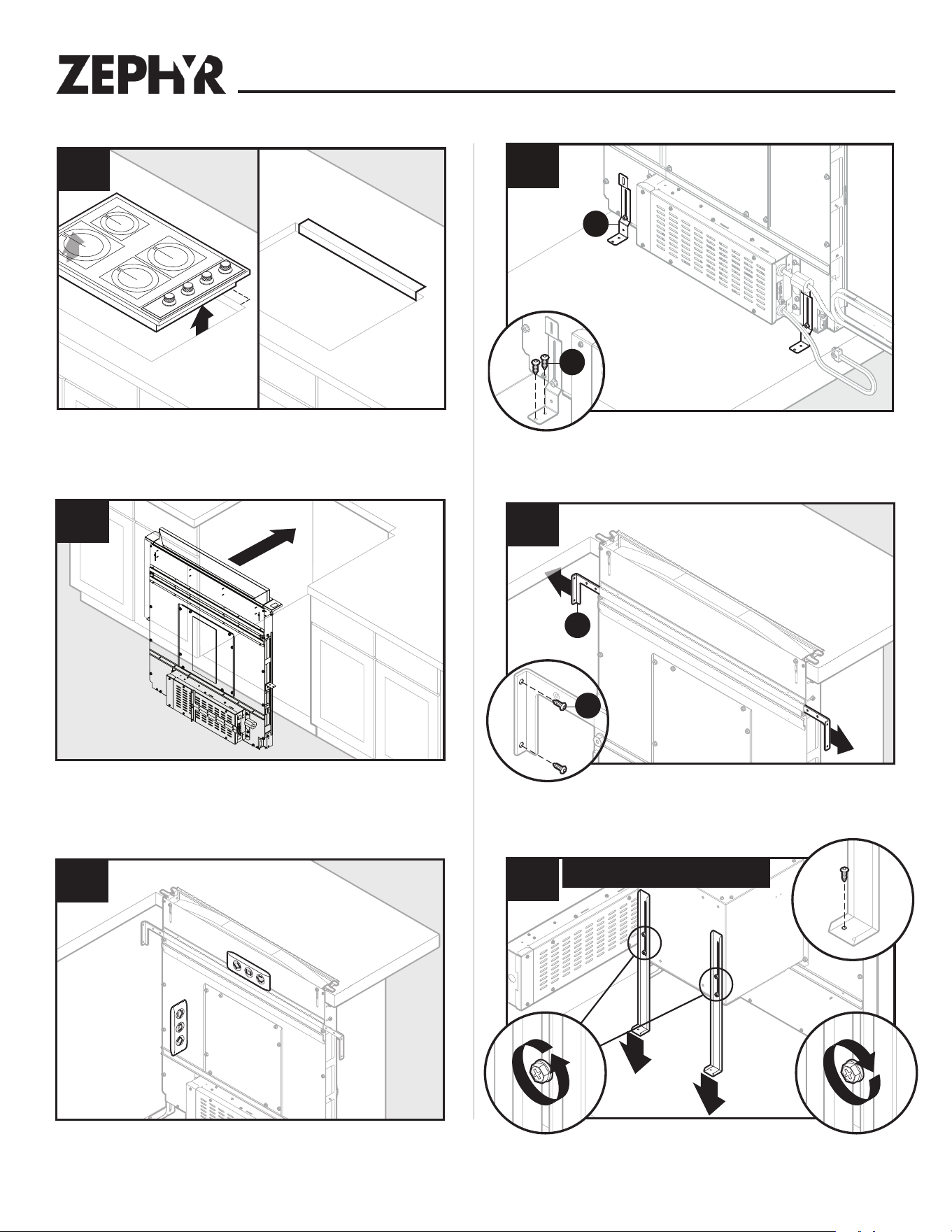
Installation
Level housing.
Note: Steps 11-15, right cabinet not shown for clarity.
Attach support legs (E) to bottom of cabinet with two screws (AA) per
leg. Tighten hex screws. Note: If cabinet bottom is removed, use blocks
as spacers between floor and support legs.
Extend upper support brackets (A) and attached to sides of cabinet with
two screws (BB) per bracket.
Remove cook top/appliance and cut opening.
Cutting Counter Top Opening (continued)
Install Housing into Cabinet
Install Housing into Cabinet (continued)
9
Set housing into cabinet.
10
11
1
1
12
2
E
AA
1
1
13
2
A
BB
Loosen four screws attaching blower support legs to DBI-600A blower.
Extend legs and secure to bottom of cabinet with one screw through
each bracket. Re-tighten four blower screws.
1
2
2
14
DBI-600A Blower Only
4
3
1
16
CAUTION
BEFORE CUTTING HOLE IN CABINET FOR
DUCTWORK, check for interference with floor
joists, wall studs, electrical wiring, or plumbing.
• Refer to Ductwork Configurations in the Planning section of this
document.
• Cut hole in cabinet as well as holes in wall or floor as necessary.
• Mount the roof or wall cap and work back towards the cabinet,
attaching all ductwork, elbows and transitions as previously
planned. Tape all ductwork connections to make them secure and
air tight.
• Connect ductwork (and transition, if required) to downdraft.
Place retaining washer on left trim cap (C). Insert hinge pin into slot of the
flip door. Position left trim cap and flip door. Align trim caps and complete
assembly by tightening trim cap nut.
Note: Make sure trim sits flat on countertop surface, is flush with top door,
and has 1/16” GAP between trim and top door.
End cap trim peices are available, extending each trim by 1”. See Optional
Accessory page for more information.
Installation
Position right trim cap (D). Place retaining washer on right trim cap. Insert
hinge pin into slot of the flip door. Secure right trim cap by trim cap nut.
Note: Make sure trim: sits flat on countertop surface, is flush with top door,
has 1/16” GAP between trim and top door, and wiring is not pinched.
Installing Finish Trim (continued)
Installing Ductwork
Door Trim
1/16" Gap
1/16" Gap
Washer
TOP VIEW
Flush
3
2
4
16
1
D
D
Retaining
Washer
Retaining
Washer
D
TOP VIEW
Flush
2
3
17
1
C
Retaining
Washer
Retaining
Washer
C
C
DoorTrim
1/16" Gap1/16" Gap
Washer
2
Installing Finish Trim
CAUTION
Only connect or disconnect UP BUTTON CABLE
with main power off for at least 60 seconds.
Insert wiring harness with wire from right upper button (D) into opening
in side of downdraft (B). Insert upper button (D) wiring harness into
receptacle at lower right side of downdraft (B).
15
1
B
D
2
17
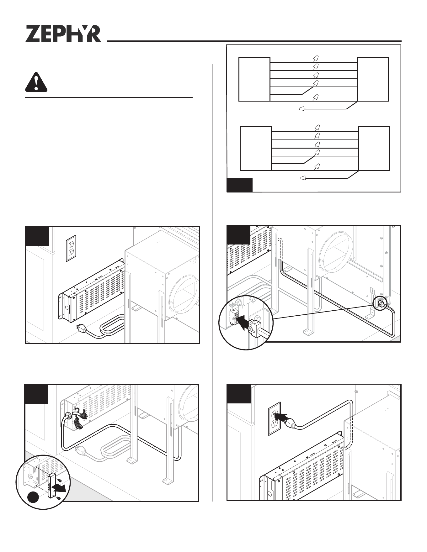
Plug downdraft’s power cord into outlet.
Note: Make sure that power cord is routed away from the heat
generated by the cooktop.
Plug electrical panel cable into lower receptacle on side of downdraft.
The DBI-600A blower is capable of maximum CFM of 600 CFM or 400 CFM.
Connect blower wires to wire in electrical panal as needed for your CFM
requirements.
Remove electrical panel (I) cover and route blower wire into wiring box.
Mount a standard wiring box, with 3-pronged receptacle, within reach
of downdraft’s power cord. (Run appropriate power cable and connect it
to receptacle.)
Electrical Wiring Installation
DBI-600A Blower only
CAUTION
All electrical wiring should be done by a qualified
person(s) in accordance with all applicable codes
and standards.
• This downdraft blower using the DBI-600A Blower (purchase
separately) draws 3.0 Amps and requires a
120 VAC, 60 Hz circuit.
• The unit has a 30 in. long power cord with a 3-pronged plug
attached to the electrical panel. Plan to provide a grounded
outlet in a location which will allow the unit’s power cord to
reach.
• Install electrical box according to local codes.
18a
19a
I
White (common)
Grey (med.) Red (med.)
Black (high)
Green (ground)
Lift
Downdraft
DBI-600A
Blower
White (common)
Blue (low)
Blue (low)
Green (ground)
Orange (high)
Black (high)
Orange (Cap Off)
20a
22a
21a21a
White (common)
Grey (med.) Red (med.)
Black (high)
Green (ground)
Lift
Downdraft
DBI-600A
Blower
White (common)
Blue (low)
Blue (low)
Green (ground)
Orange (high)
Orange (high)
Black (Cap Off)
600 CFM WIRING SET UP
400 CFM WIRING SET UP
18
Electrical Wiring Installation
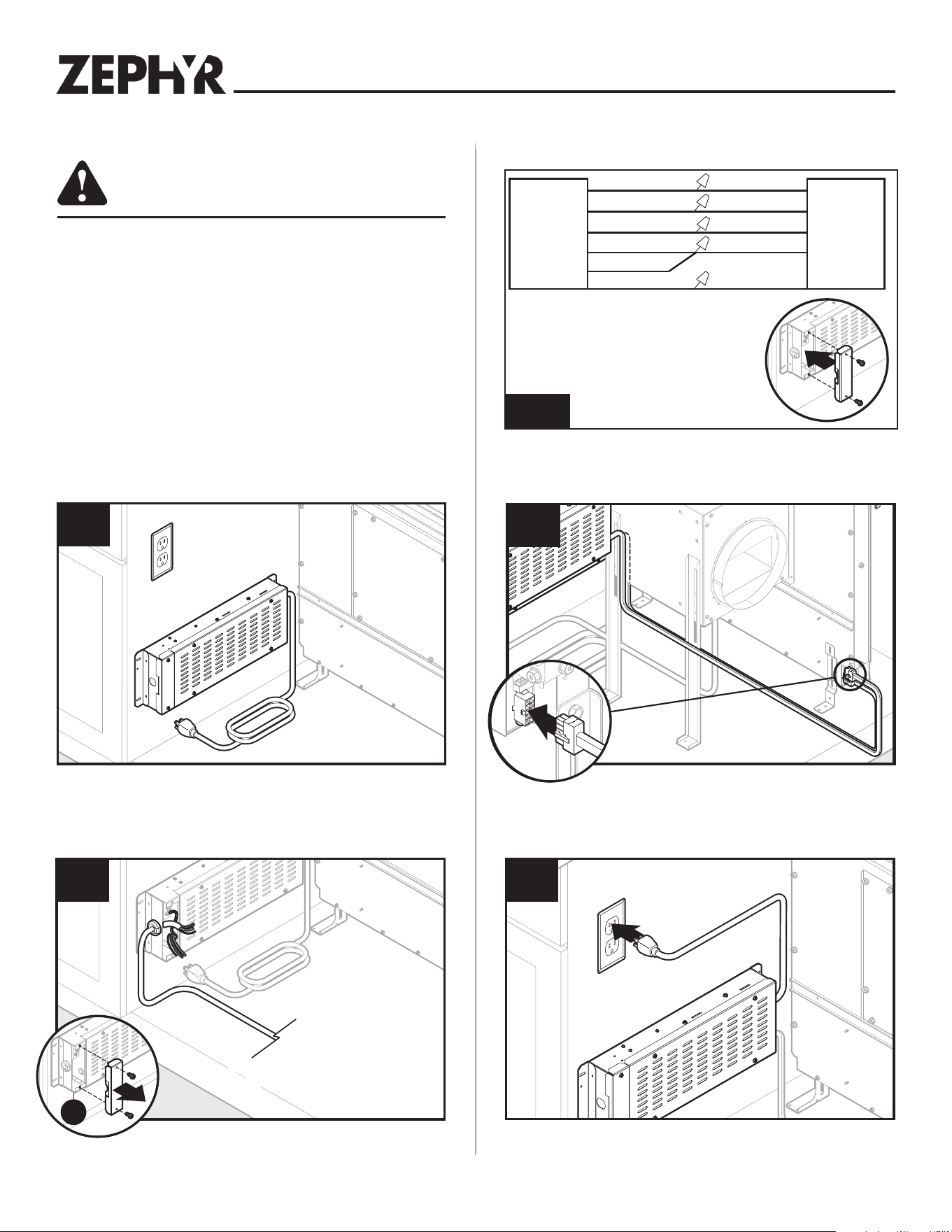
Plug downdraft’s power cord into outlet.
Note: Make sure that power cord is routed away from the heat gen-
erated by the cooktop.
Plug electrical panel cover into lower receptacle as shown.
Connect blower wires to wires in wiring box. Replace wiring box cover.
Mount a standard wiring box, with 3-pronged receptacle, within
reach of downdraft’s power cord. Run appropriate power cable and
connect it to receptacle.
CAUTION
All electrical wiring should be done by a qualified
person(s) in accordance with all applicable codes
and standards.
• If using a remote blower (purchase separately), the
system draws 6.0 Amps (max.) and requires a 120 VAC,
60 Hz circuit.
• The unit has a 30 in. long power cord with a 3-pronged plug
attached to the electrical panel. Plan to provide a grounded
outlet in a location which will allow the unit’s power cord to
reach.
• Install electrical box according to local codes.
Exterior or In-Line Blower only
18b
22b
20a21b
Remove wiring box cover and route blower wire into wiring box.
From Exterior or
In-Line Blower
From Exterior or
In-Line Blower
19b
I
White (Common)
Gray (Med.) Blue (Med.)
Black (High)
Greed (Ground)
Lift
Downdraft
Remote
Blower
White (Common)
Blue (Low)
Red (Low)
Green (Ground)
Orange (High)
Black (High)
20b
19
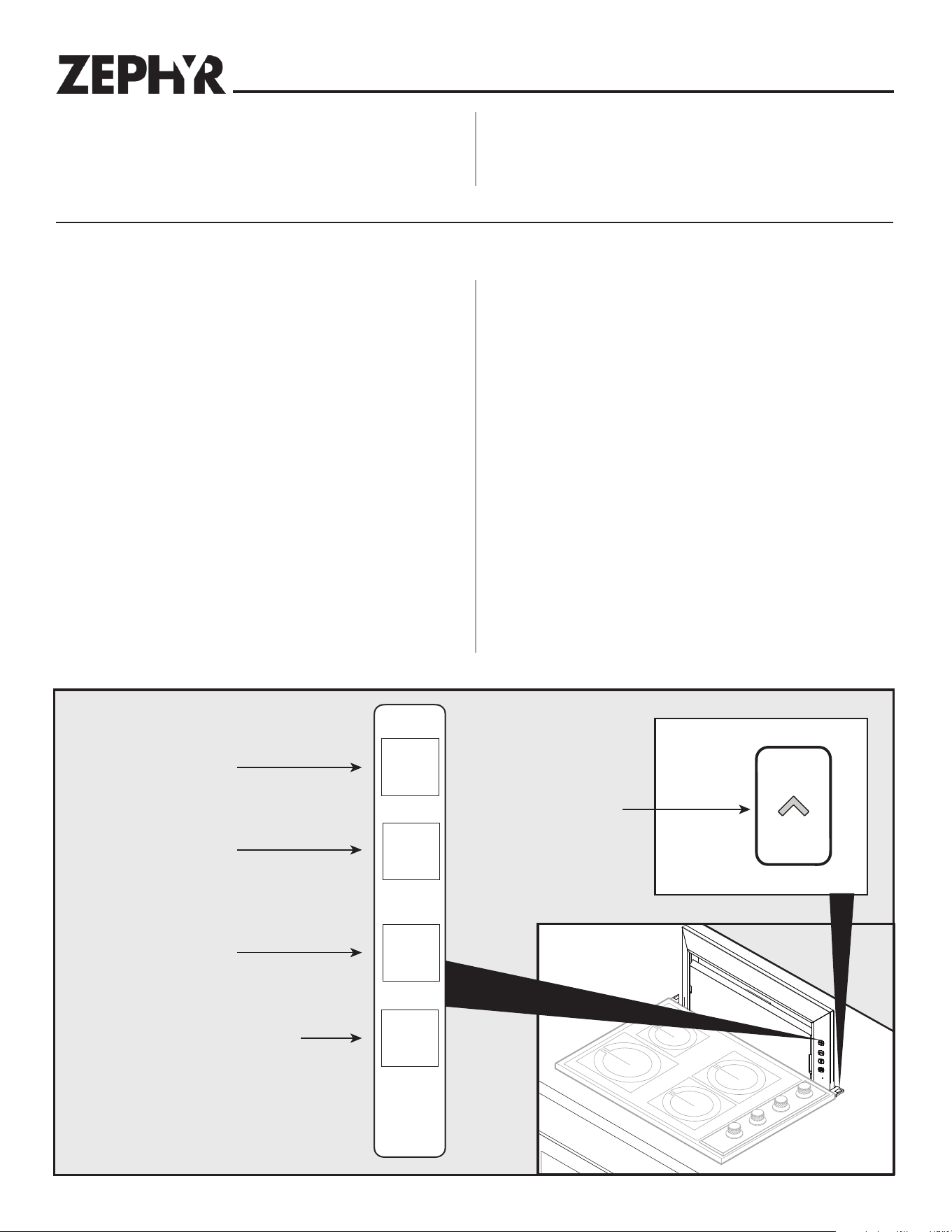
Appliance Installation/Operation
Fan + Button
• Press to increase fan speed.
• After maximum speed is reached, press + button once more to
turn fan off.
Fan - Button
• Press to decrease fan speed.
• After minimum speed is reached, press - button once more to
turn fan off.
2 Level Light Control
• Press once for dim level.
• Press 2x for bright level.
• Press 3x to turn light off.
30-Hour Filter Clean Reminder
• After 30 hours of blower “ON” time, filter clean icon will blink
continuously.
• To reset, touch and hold icon for 2 or more seconds. Indicator
will turn off.
Up/Down Button
• To retract chimney, touch down button. Any feature that is
active will shut off.
• Touch up button on right trim to raise chimney. All functions will
return to their previous settings.
Fan +
Fan -
Light
Filters
Increase Fan Speed
Decrease Fan Speed
2 Level Light Control
30-Hour Filter Clean Reminder
Up/Down Button
Control Panel and Up Button
Install Cooking Appliance
1. Align the cooking appliance with downdraft and fasten appliance
in place following appliance instructions.
Note: Accurate alignment of cooking appliance and downdraft is
necessary to ensure that there is no interference when air vent is
raised and lowered. There should be a gap of 1/32" - 1/16" between
the back of the cooktop and the front of the downdraft cover.
20
Use and Care
Cooking
WARNING
Always disconnect electric power
supply before cleaning and/or servicing unit.
Always turn the downdraft blower on before you begin cooking
to establish an air flow in the kitchen. Let the blower run for a few
minutes to clean the air after you turn the cooktop off. This will
keep the whole kitchen cleaner and brighter.
It is recommended to use the rear burners when cooking with tall
pots or when the cooking method will generate high amounts of
smoke or steam. The combination of using the rear burners and
operating the unit at high speed will increase the likelihood that
all the smoke and steam will be removed by the downdraft.
Cleaning
CAUTION
To Clean grease filters:
Lift FRONT PANEL up and out and take out the GREASE FILTERS.
Wash filters in a mild detergent solution or a dishwasher. Replace
filters and front panel before using downdraft.
Filter
Filter
Front Panel
CAUTION
To clean inside chimney:
Lift FRONT PANEL up and out and take out the GREASE FILTERS.
Use a mild detergent. DO NOT USE ABRASIVE CLOTH, STEEL WOOL
PADS, OR SCOURING POWDERS. Replace filters and front panel
before using downdraft.
Servicing
It may be necessary to remove the downdraft blower system from
the cabinet in order to service components such as the blower
motor or air vent mechanism.
Disconnect power to the cooktop and remove it first. Reverse the
steps under “INSTALL HOUSING INTO CABINET” to remove the
downdraft from the cabinet.
21
Optional Accessories
Accessory Description
Model DDA-0002
REMOTE UP/DOWN CONTROL
Use when you cannot reach the UP/
DOWN Button on the downdraft chimney.
Can be located on counter top, face of
cabinetry or on the side cabinet of an
island. Cut-out size: 2 1/4" H x 2" W
Cannot be used where remote control
will interfere with cooking, where hot
pans could be set, or where hot liquids
could be spilled on the control.
(Remote wiring connects with 6-pin
connection)
MODELS
DDS-0030
DDS-0036
GAS COOKTOP SEAL KIT
Recommended for use with all gas
cooktops. Includes trim bracket and trim
seal.
30", 36" widths.
MODELS
MUA008A
MUA010A
MAKE-UP AIR DAMPER
Use to provide make-up air (when called
for) to keep the home comfortable by
allowing the downdraft to operate at
optimum levels.
MODELS
DDT-0030
DDT-0036
RANGE TRIM KIT
Use with free-standing range - where a
gap is present between back of range
and downdraft.
30", 36" widths.
Accessory Description
MODEL 11030132
EXTENSION CABLE - 5-FT.
Use where electrical panel is remotely
mounted. Extends electrical panel cable
an additional 5 feet.
MODEL ZRC-00LF NON-DUCT RECIRCULATING KIT
Use where ducting is not feasible or
available. Mount to toe kick or base of
a cabinet and attach directly to Model
DBI-600A Blower using 8" round duct.
Kit can be rotated so that the exhaust is
not directly at your feet. Includes
recirculating filter and decorative
cover plate.
MODEL Z0F-C006
RECIRCULATION FILTER REPLACEMENT
Replacement filter for ZRC-00LF Non-
Duct Recirculating Kit. Use to effectively
capture cooking contaminants.
MODEL AK00070
1-7/8" X 19” TO 8" ROUND
TRANSITION
Rectangular to 8" round transition for
left, right, or rear exhaust - using Model
DBI-600A Blower. Can be attached
to downdraft unit or rectangular duct
(AK00072). Includes S-clips for easy,
secure attachment.
MODEL AK00071
1-7/8" X 19" TO 10" ROUND
TRANSITION
Rectangular to 10" round transition for
left, right, or rear exhaust - using
external blower. Can be attached to
downdraft unit or rectangular duct
(AK00072).
MODEL AK00072
RECTANGULAR ADAPTOR FOR
1-7/8" X 19"
Use to connect 1-7/8" x 19" rectangular
duct directly to downdraft when using
side or rear exhaust.
Optional Accessories
22
Optional Accessories
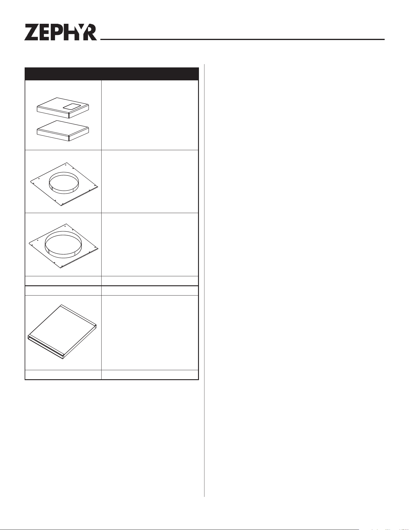
Accessory Description
MODEL DDE-0001
END CAP TRIM EXTENSION +1"
WIDTH - LH & RH
Use left and right to increase the overall
trim width by 1".
MODEL 54190053
FRONT PANEL ROUGH-IN PLATE -
8" ROUND
Use where 8" round duct or elbow
attaches to front of airbox (Model DBI-
600A used as remote blower installa-
tion).
MODEL 54190054
FRONT PANEL ROUGH-IN PLATE -
10" ROUND
Use where 10" round duct or elbow
attaches to front of airbox (exterior or
in-line blower installation).
MODEL AK00080
RECTANGULAR DUCT - 2-FT.
SECTIONS (1-7/8" X 19")
Galvanized steel construction.
Optional Accessories (continued)
23
Blower duct routing configuration A
MODEL DBI-600
Internal Blower (sold separately)
(“Down” discharge shown. Blower can
also be rotated for “Left” or “Right”
discharge.)
8-inch Round
Wall Cap*
8-inch Round
Straight Duct*
* As required - sourced locally.
MODEL ZRC-00LF
Non-Duct Recirculating Kit with
Kickspace Grille (sold separately)
(Only required for non-duct
applications. “Front” discharge
shown. Kit can also be rotated for
“Left” , “Right” or “Rear” discharge.)
MODEL 11030132
5-foot Extension
Cable (sold separately)
(Only required if electrical panel
is more than 2-feet away from
downdraft. Use up to 2 extension
cables connected together.)
Electrical Panel
(Mount in remote location)
8-inch Round
Straight Duct*
Internal Blower (DBI-600A) - Front Mounted to Downdraft
8-inch Round Elbow*
24
MODEL 54190053
8-inch Round Front
Rough-in Plate
(sold separately)
MODEL 11030132
5-foot Extension Cable
(sold separately)
(Only required if electrical panel
is mounted in a remote location -
more than 2-feet away from
downdraft. Use up to 2 extension
cables connected together.)
8-inch Round Elbow*
8-inch Round
Straight Duct*
Electrical Panel
(Can be mounted
in remote location)
8-inch Round
Straight Duct*
8-inch Round
Wall Cap*
MODEL DBI-600A
Internal Blower (sold separately)
* As required - sourced locally
Internal Blower (DBI-600A) - Remote Mounted - Front Outlet
Blower duct routing configuration B
25
Blower duct routing configuration C
MODEL ZRC-00LF
Non-Duct Recirculating Kit
with Kickspace Grille
(sold separately)
(Only required for non-duct
applications. “Front” discharge
shown. Kit can also be rotated
for “Left” , “Right” or “Rear” discharge.)
MODEL AK00072
1-7/8-inch x 19-inch
Rectangular Transition
(sold separately)
(Only required to
extend duct along
back of cabinet.)
MODEL AK00080
1-7/8-inch x 19-inch
Rectangular Duct
(sold separately)
(Only required to
extend duct along
back of cabinet.)
MODEL AK00070
1-7/8-inch to 8-inch
Round Transition
(sold separately)
MODEL DBI-600A
Internal Blower
(sold separately)
(Mounted in
adjacent cabinet)
MODEL DBI-600A
Internal Blower
(sold separately)
(Mounted in
adjacent cabinet)
8-inch Round
Straight Duct*
8-inch Round
Straight Duct*
8-inch Round
Elbow*
8-inch Round
Wall Cap*
MODEL 11030132
5-foot Extension Cable
(sold separately)
(Only required if
electrical panel is mounted
in a remote location - more
than 2-feet away from downdraft.
Use up to 2 extension cables
connected together.)
Electrical Panel
(Can be mounted in
remote location.)
* As required - sourced locally
Internal Blower (DBI-600A) - Remote Mounted - Side Outlet
8-inch Round
Straight Duct*
26
Blower duct routing configuration D
MODEL ZRC-00LF
Non-Duct Recirculating Kit
with kickspace grille
(sold separately)
(Only required for non-duct
applications. “Front” discharge
shown. Kit can also be rotated
for “Left” , “Right” or “Rear” discharge.)
MODEL AK00072
1-7/8-inch x 19-inch
Rectangular Transition
(sold separately)
MODEL AK00080
1-7/8-inch x 19-inch
Rectangular Duct
(sold separately)
MODEL AK00070
1-7/8-inch to 8-inch
Round Transition
(sold separately)
MODEL DBI-600A
Internal Blower
(sold separately)
(Mounted in
adjacent cabinet)
8-inch Round
Straight Duct*
8-inch Round
Straight Duct*
8-inch Round
Elbow*
MODEL DBI-600A
Internal Blower
(sold separately)
(Mounted in
remote location)
8-inch Round
Wall Cap*
8-inch Round
Straight Duct*
* As required - sourced locally
Internal Blower (DBI-600A) - Remote Mounted - Rear Outlet
27
Blower duct routing configuration E
MODEL DBI-600A
Internal Blower
(sold separately)
(Mounted in
adjacent cabinet)
8-inch Round
Straight Duct*
8-inch Round
Wall Cap*
Electrical Panel
(Can be mounted in
remote location.)
MODEL AK00070
1-7/8-inch x 19-inch
to 8-inch Round Transition
(sold separately)
8-inch Round
Straight Duct*
MODEL ZRC-00LF
Non-Duct Recirculating Kit
with Kickspace Grille
(sold separately)
(Only required for non-duct
applications. “Front” discharge
shown. Kit can also be rotated
MODEL DBI-600A
Internal Blower
(sold separately)
(Mounted in
adjacent cabinet)
8-inch Round
Straight Duct*
8-inch Round
Elbow*
MODEL 11030132
5-foot Extension Cable
(sold separately)
(Only required if
electrical panel is mounted
in a remote location - more
than 2-feet away from downdraft.
Use up to 2 extension cables
connected together.)
Internal Blower (DBI-600A) - Remote Mounted - Below Outlet
28
Blower duct routing configuration F
MODEL 11030132
5-foot Extension Cable
(sold separately)
(Only required if
Electrical Panel is mounted
in a remote location - more
than 2-feet away from downdraft.
Use up to 2 Extension Cables
connected together.)
MODEL
54190054
10-inch Round
Front Rough-in Plate
(sold separately)
10-inch Round Elbow*
10-inch Round Elbow*
10-inch Round Straight Duct*
MODEL PBN-1000A
1,100 cfm
10-inch Round
In-Line Blower**
10-inch Round
Straight Duct*
10-inch Round
Wall Cap*
Electrical Panel
(Can be mounted in
remote location.)
(Standard 120 VAC
wiring rated for 6A
minimum - sold separately.)
* As required - sourced locally.
** Choose 1 external or in-line
blower - sold separately.
MODEL CBE-1000
1,000 cfm
10-inch Round
External Blower**
External or In-Line Blower - Front Outlet
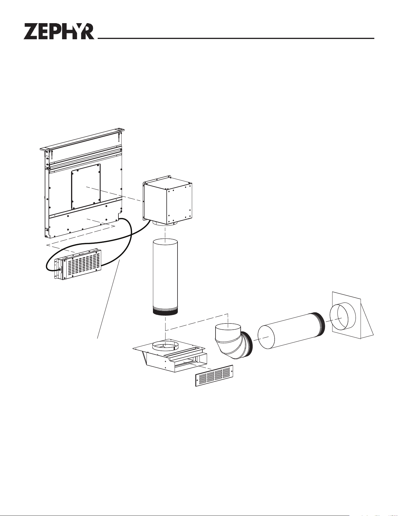
29
Blower duct routing configuration G
MODEL AK00072
1-7/8-inch x 19-inch
Rectangular Transition
(sold separately)
(Only required to extend
duct along back of cabinet)
MODEL 11030132
5-foot Extension Cable
(sold separately)
(Only required if
Electrical Panel is mounted
in a remote location - more
than 2-feet away from downdraft.
Use up to 2 extension cables
connected together.)
MODEL AK00080
1-7/8-inch x 19-inch
Rectangular Duct
(sold separately)
(Only required to
extend duct along
back of cabinet.)
MODEL AK00071
1-7/8-inch to 10-inch
Round Transition
(sold separately)
10-inch Round Elbow*
10-inch Round Elbow*
10-inch Round Straight Duct*
10-inch Round
Straight Duct*
10-inch Round
Wall Cap*
Electrical Panel
(Can be mounted in
remote location)
(Standard 120 VAC
wiring rated for 6A
minimum - sold separately)
* As required - sourced locally.
** Choose 1 external or in-line
blower - sold separately.
MODEL PBN-1000A
1,100 cfm
10-inch Round
In-Line Blower**
MODEL CBE-1000
1,000 cfm
10-inch Round
External Blower**
External or In-Line Blower - Side or Rear Outlet
30
Blower duct routing configuration H
Electrical Panel
(Can be mounted in
remote location.)
MODEL AK00071
1-7/8-inch x 19-inch
to 10-inch Round Transition
(sold separately)
MODEL 11030132
5-foot Extension Cable
(sold separately)
(Only required if
electrical panel is mounted
in a remote location - more
than 2-feet away from downdraft.
Use up to 2 extension cables
connected together.)
10-inch Round Elbow*
10-inch Round Straight Duct*
10-inch Round
Straight Duct*
10-inch Round
Wall Cap*
(Standard 120 VAC
wiring rated for 6 A
minimum - sold separately.)
* As required - sourced locally.
** Choose 1 external or in-line
blower - sold separately.
MODEL PBN-1000A
1,100 cfm
10-inch Round
In-Line Blower**
MODEL CBE-1000
1,000 cfm
10-inch Round
External Blower**
External or In-Line Blower - Below Outlet
31
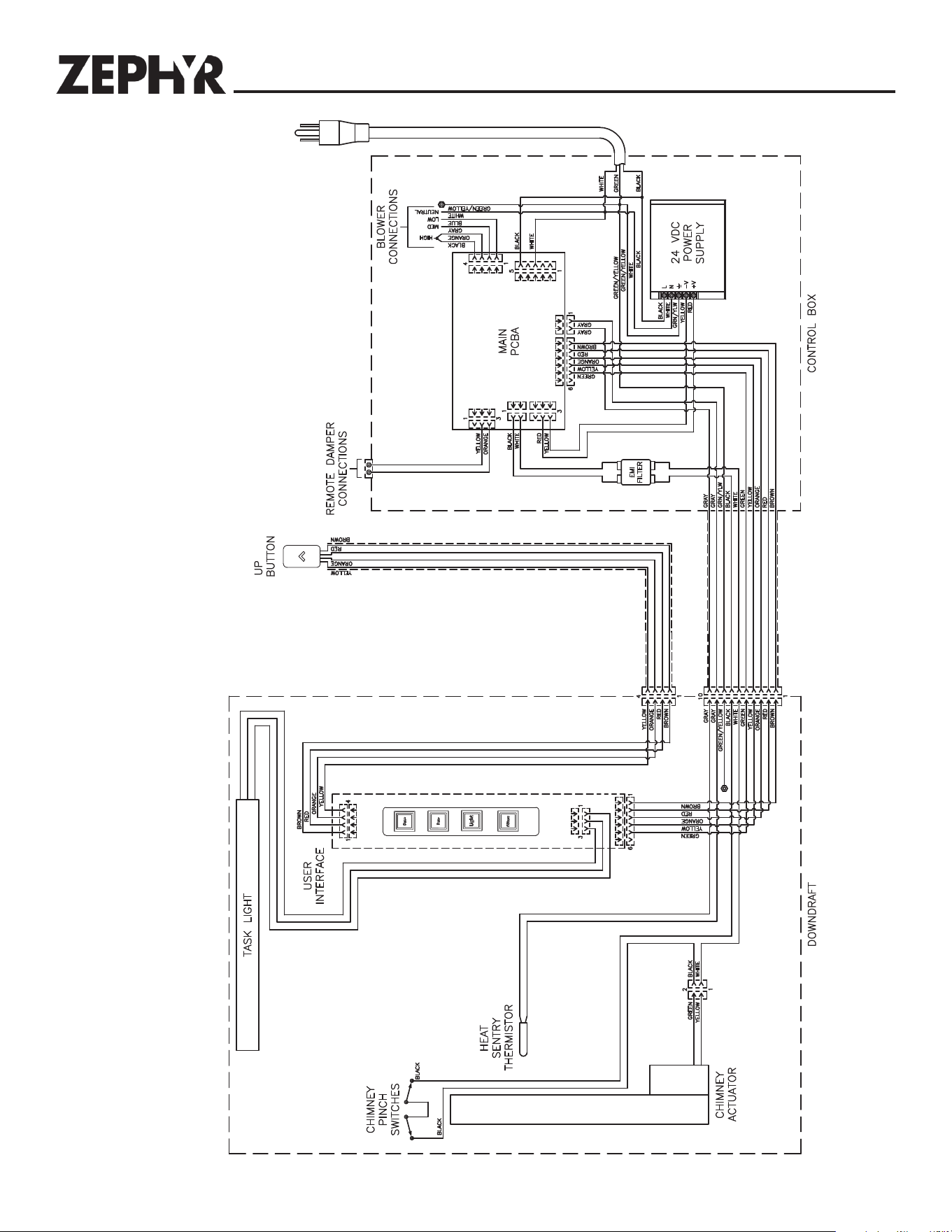
DESU TON
Wiring Diagram
32
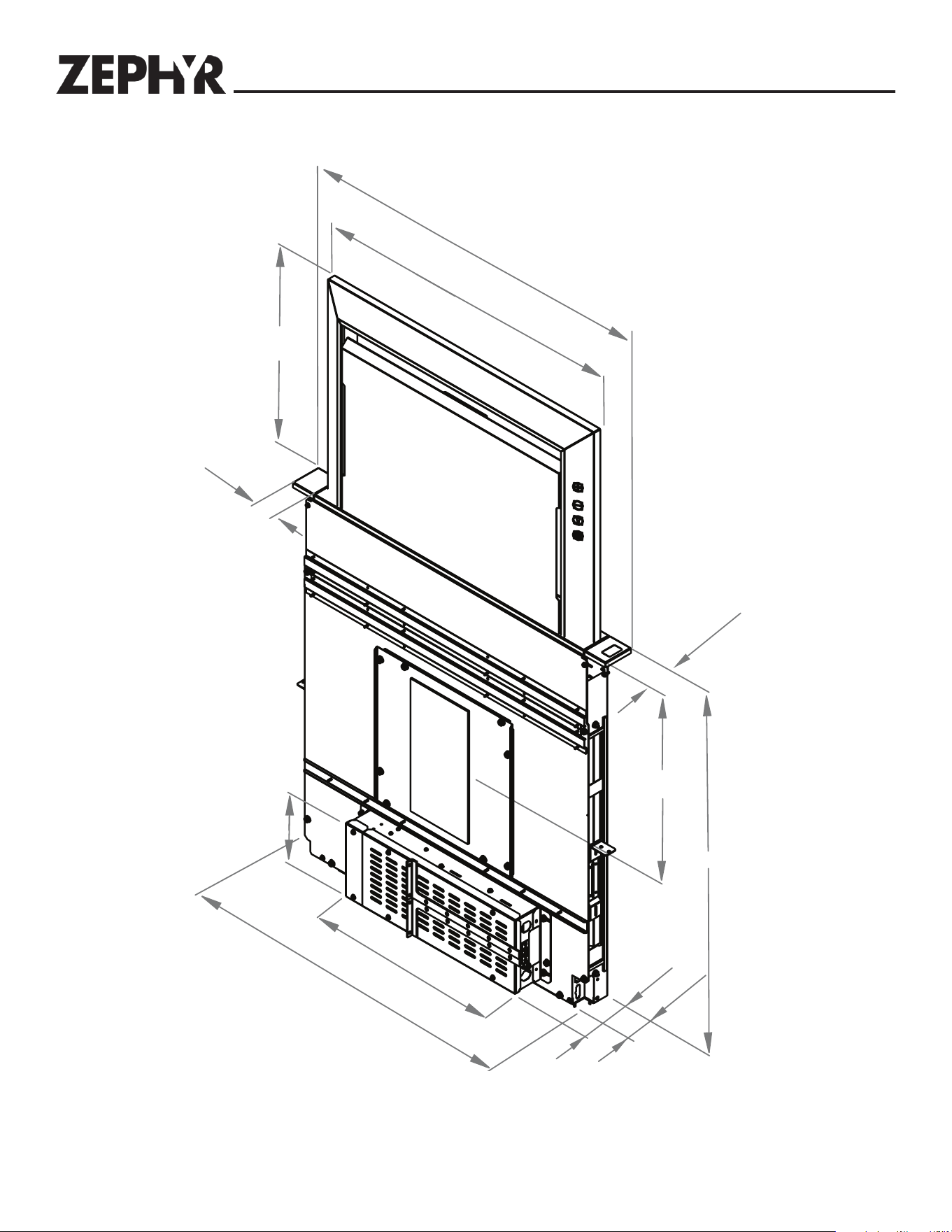
Dimensional Drawing
3
0
”
,
3
6
”
2
5-1
/
2
”
, 31-1/2
”
2-1/2”
15-1/8”
29-3/8”
27-1
/
4
”,
3
3
-
1
/
4
”
5”
18”
2”
16-1
/
4
”
6-1/4”
2-1/2”

33
OCT17.0301
Zephyr Ventilation, LLC (referred to herein as “we” or “us”) warrants to the original consumer purchaser (referred to herein
as “you” or “your”) of Zephyr products (the “Products”) that such Products will be free from defects in materials or
workmanship as follows:
Two Year Limited Warranty for Parts: For two years from the date of your original purchase of the Products, we will
provide, free of charge, Products or parts (including LED light bulbs, if applicable) to replace those that failed due to
manufacturing defects subject to the exclusions and limitations below. We may choose, in our sole discretion, to repair or
replace parts before we elect to replace the Products.
One Year Limited Warranty for Labor: For one year from the date of your original purchase of the Products, we will
provide, free of charge, the labor cost associated with repairing the Products or parts to replace those that failed due to
manufacturing defects subject to the exclusions and limitations below. After the first year from the date of your original
purchase, you are responsible for all labor costs associated with this warranty.
Warranty Exclusions: This warranty covers only repair or replacement, at our option, of defective Products or parts and
does not cover any other costs related to the Products including but not limited to: (a) normal maintenance and service
required for the Products and consumable parts such as fluorescent, incandescent or halogen light bulbs, mesh and char-
coal filters and fuses; (b) any Products or parts which have been subject to freight damage, misuse, negligence, accident,
faulty installation or installation contrary to recommended installation instructions, improper maintenance or repair (other
than by us); (c) commercial or government use of the Products or use otherwise inconsistent with its intended purpose; (d)
natural wear of the finish of the Products or wear caused by improper maintenance, use of corrosive and abrasive cleaning
products, pads, and oven cleaner products; (e) chips, dents or cracks caused by abuse or misuse of the Products; (f) service
trips to your home to teach you how to use the Products; (g) damage to the Products caused by accident, fire, floods, acts
of God; or (h) Custom installations or alterations that impact serviceability of the Products. If you are outside our service
area, additional charges may apply for shipping costs for warranty repair at our designated service locations and for the
travel cost to have a service technician come to your home to repair, remove or reinstall the Products. After the first year
from the date of your original purchase, you are also responsible for all labor costs associated with this warranty. All Products
must be installed by a qualified professional installer to be eligible for warranty repairs or service.
Limitations of Warranty. OUR OBLIGATION TO REPAIR OR REPLACE, AT OUR OPTION, SHALL BE YOUR SOLE
AND EXCLUSIVE REMEDY UNDER THIS WARRANTY. WE SHALL NOT BE LIABLE FOR INCIDENTAL,
CONSEQUENTIAL OR SPECIAL DAMAGES ARISING OUT OF OR IN CONNECTION WITH THE USE OR
PERFORMANCE OF THE PRODUCTS. THE EXPRESS WARRANTIES IN THE PRECEDING SECTION ARE
EXCLUSIVE AND IN LIEU OF ALL OTHER EXPRESS WARRANTIES. WE HEREBY DISCLAIM AND EXCLUDE ALL
OTHER EXPRESS WARRANTIES FOR THE PRODUCTS, AND DISCLAIM AND EXCLUDE ALL WARRANTIES
IMPLIED BY LAW, INCLUDING THOSE OF MERCHANTABILITY AND FITNESS FOR A PARTICULAR PURPOSE.
Some states or provinces do not allow limitations on the duration of an implied warranty or the exclusion or limitation of
incidental or consequential damages, so the above limitations or exclusions may not apply to you. To the extent that
applicable law prohibits the exclusion of implied warranties, the duration of any applicable implied warranty is limited to the
same two-year and one-year periods described above if permitted by applicable law. Any oral or written description of the
Products is for the sole purpose of identifying the Products and shall not be construed as an express warranty. Prior to
using, implementing or permitting use of the Products, you shall determine the suitability of the Products for the intended
use, and you shall assume all risk and liability whatsoever in connection with such determination. We reserve the right to
use functionally equivalent refurbished or reconditioned parts or Products as warranty replacements or as part of warranty
service. This warranty is not transferable from the original purchaser and only applies to the consumer residence where the
Product was originally installed located in the United States and Canada. This warranty is not extended to resellers.
To Obtain Service Under Limited Warranty: To qualify for warranty service, you must: (a) notify us at the address or
telephone number stated below within 60 days of the discovery of the defect; (b) give the model number and serial number;
and (c) describe the nature of any defect in the Product or part. At the time of the request for warranty service, you must
present evidence of your proof of purchase and proof of the original purchase date. If we determine that the warranty
exclusions listed above apply or if you fail to provide the necessary documentation to obtain service, you will be responsible
for all shipping, travel, labor and other costs related to the services. This warranty is not extended or restarted upon warranty
repair or replacements.
Please check our website for any additional Product information,
www.zephyronline.com.
Zephyr Ventilation Service Department, 2277 Harbor Bay Parkway, Alameda, CA 94502 1-888-880-8368
Warranty

34