MODEL VT-81009
SKU 23425
INPUT VOLTAGE AC: 220-240V, 50/60 Hz
RATED LOAD
Max. 500W
200W +LED
TIME DELAY
Min. 10sec ±3sec
Max. 7min ±2min
DETECTION
RANGE
120°
DETECTION
DISTANCE
10m Max (<24° C)
DETECTION
MOTION SPEED
0.6-1.5m/s
WORKING
TEMPERATURE
-20°C to +40°C
WORKING
HUMIDITY
<93%RH
AMBIENT LIGHT <3-2000 LUX (Adjustable)
IP RATING
IP20
In case of any query/issue with the product, please reach out to us at: support@v-tac.eu
For More products range, inquiry please contact our distributor or nearest dealers.
V-TAC EUROPE LTD. Bulgaria, Plovdiv 4000, bul.L.Karavelow 9B
MULTI-LANGUAGE
MANUAL QR CODE
Please scan the QR code
to access the manual in
multiple languages.
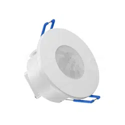
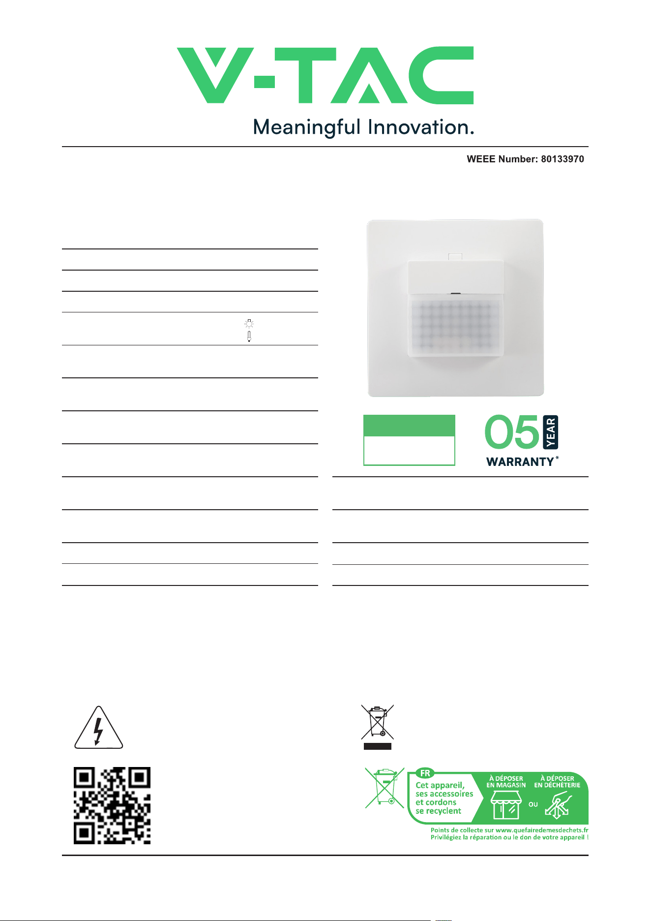
INSTRUCTION MANUAL
INFRARED MOTION SENSOR
TECHNICAL DATA
INTRODUCTION & WARRANTY
Thank you for selecting and buying V-TAC product. V-TAC will serve you the best. Please read these instructions
carefully before starting the installation and keep this manual handy for future reference. If you have any another
query, please contact our dealer or local vendor from whom you have purchased the product. They are trained
and ready to serve you at the best. The warranty is valid for 5 years from the date of purchase. The warranty
does not apply to damage caused by incorrect installation or abnormal wear and tear. The company gives no
warranty against damage to any surface due to incorrect removal and installation of the product.
V-TAC LED
RANGE (UPTO 200W)
COMPATIBLE WITH
This marking indicates that this
product should not be disposed
of with other household wastes.
Caution, risk of electric shock.
POWER
CONSUMPTION
approx 0.9w
INSTALLATION
HEIGHT
1-1.8m
CUTOUT SIZE
XXXX
DIMENSION 80x80x43.5 mm
FUNCTION
1. Can identify day and night: The consumer can adjust working state in dierent ambient light.
It can work in the daytime and at night when it is adjusted on the “sun” position (max). It can
work in the ambient light less than 3LUX when it is adjusted on the “moon” position (min). As
for the adjustment pattern, please refer to the testing pattern.
2. Time-Delay is added continually: When it receives the second induction signals within the first
induction, it will restart to time from the moment.
3. The switch: “ON”,“OFF”,“PIR”.
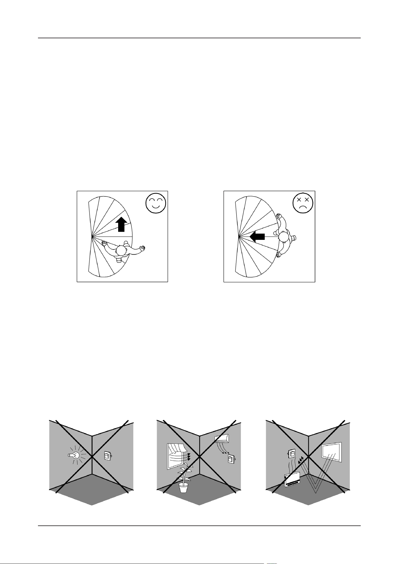
As the detector responds to changes in temperature, avoid the following situations:
INSTALLATION ADVICE
• Avoid pointing the detector towards objects with highly reflective surfaces,
such as mirrors etc.
• Avoid mounting the detector near heat sources, such as heating vents, air
conditioning units, light etc.
• Avoid pointing the detector towards objects that may move in the wind, such
as curtains, tall plants etc.
Good Sensitivity Poor Sensitivity
WARNING
1. Please make sure to turn o the power before starting the installation.
2. Installation must be performed by a qualified electrician.
3. Cover or shied any adjacent live components.
4. For indoor use only.
DO NOT PUT THE SENSOR
INTO POWER DIRECTLY!
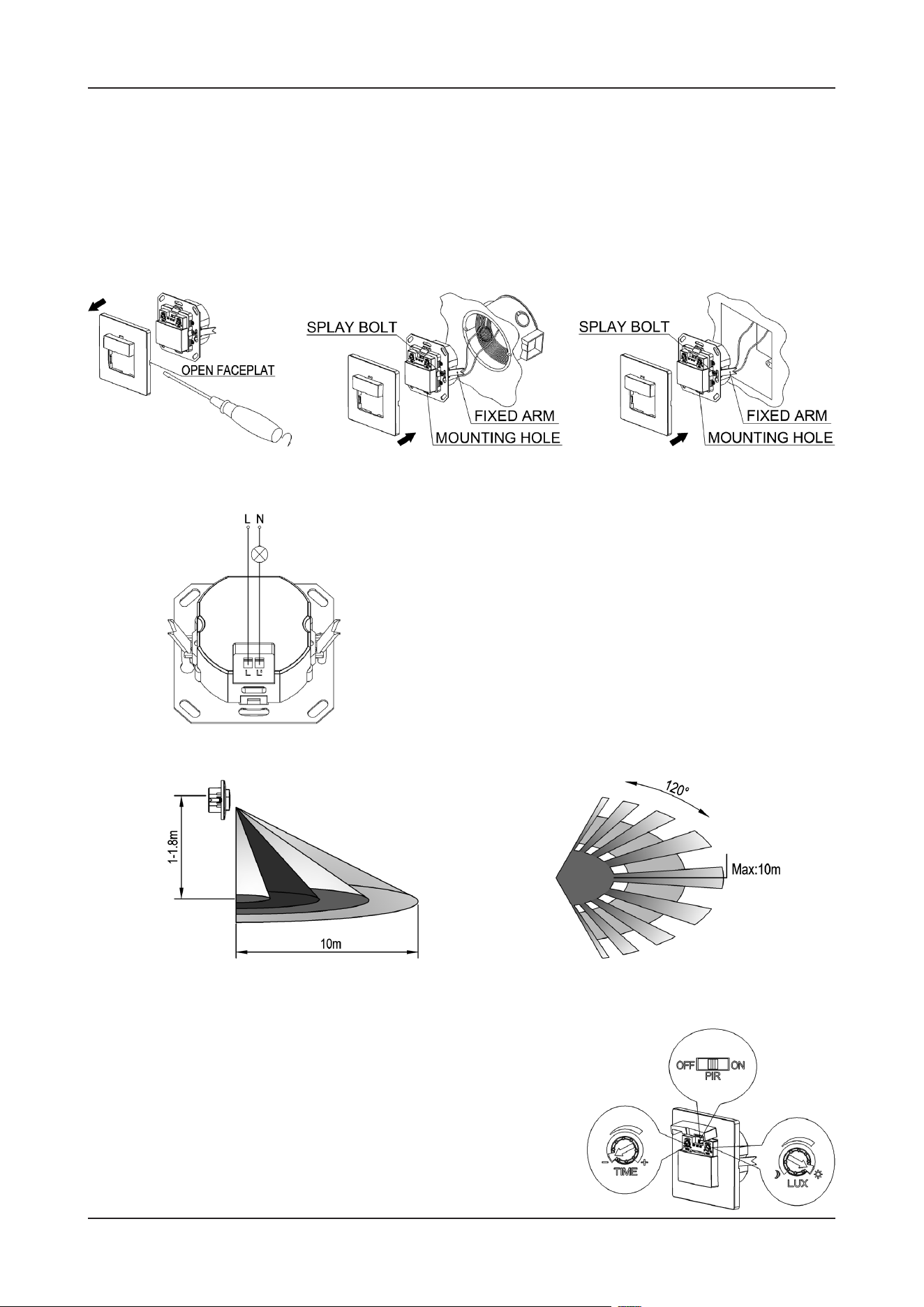
CONNECTION
WIRING DIAGRAM
SENSOR INFORMATION
TEST
• Set the function switch to “ON”, set “TIME” anti-clock-
wise to minimum (-), “LUX” clockwise to maximum (sun).
• Switch on the power, the lamp should be on.
• Set the function switch to “OFF”, the lamp should be o
immediately.
• Set the function switch to “PIR”,Switch on the power;
the sensor and its connected lamp will have no signal
• Unload the faceplate of sensor and adjust the time and LUX knob.(refer to figure 1)
• Loose the screws in the connection terminal, and then connect the power to connection
terminal of sensor according to connection-wire diagram.
• If you want to install it in circular hole, put the sensor into the hole and tighten the splay
bolt on both sides (refer to figure 2). If you want to install in quadrate hole, put the sen-
sor into the hole, fix the screw through the mounting hole (refer to figure 3).
• Install back the faceplate, switch on the power and then test it.
Height of Installation: 1-1.8m DETECTION DISTANCE: Max. 10m

• The load does not work:
a. Please check if the connection of power source and load is correct.
b. Please check if the load is good.
c. Please check if the settings of working light correspond to ambient light.
• The sensitivity is poor:
a. Please check if there is any hindrance in front of the detector to aect it to receive the signals.
b. Please check if the ambient temperature is too high.
c. Please check if the induction signal source is in the detection field.
d. Please check if the installation height corresponds to the height required in the instruction.
e. Please check if the moving orientation is correct.
• The sensor can not shut o the load automatically:
a. Please check if there is continual signal in the detection field.
b. Please check if the time delay is set to the maximum position.
TROUBLESHOOTING
Note: when testing in daylight, please turn LUX knob to ☼ (SUN) position, Otherwise the
sensor lamp will not work.
at the beginning. Aer Warm-up 30sec,the sensor can start work. If the sensor receives the
induction signal, the lamp will turn on. While there is no another induction signal any more,
the load should stop working within 10sec±3sec and the lamp would turn o.
• Set “LUX” anti-clockwise to minimum (moon), if the ambient light is more than 3LUX, the in-
ductor load should not work aer the load stop working. If the ambient light is less than 3LUX
(darkness), the sensor would work. Under no induction signal condition, the load should stop
working within 10sec±3sec.