
Programmable Controller
FP7 Multi-wire Link Unit
User's Manual
Supported models
● AFP7MW
WUME-FP7MW-06
2024.4 industry.panasonic.com/

(MEMO)
2 WUME-FP7MW-06

Introduction
Thank you for buying a Panasonic product. Before you use the product, please carefully read
the installation instructions and the user’s manual, and understand their contents in detail to
use the product properly.
Types of Manual
● There are different types of user’s manual for the FP7 series, as listed below. Please refer to
a relevant manual for the unit and purpose of your use.
● The manuals can be downloaded on our website: https://industry.panasonic.com/global/en/
downloads/?tab=manual
Unit name or purpose of
use
Manual name Manual code
FP7 Power Supply Unit FP7 CPU Unit User’s Manual
(Hardware)
WUME-FP7CPUH
FP7 CPU Unit
FP7 CPU Unit Command Reference Manual WUME-FP7CPUPGR
FP7 CPU Unit User’s Manual
(Logging Trace Function)
WUME-FP7CPULOG
FP7 CPU Unit User’s Manual
(Security Function)
WUME-FP7CPUSEC
Instructions for Built-in
LAN Port
FP7 CPU Unit User’s Manual
(LAN Port Communication)
WUME-FP7LAN
FP7 CPU Unit User’s Manual
(Ethernet Expansion Function)
WUME-FP7CPUETEX
FP7 CPU Unit User’s Manual
(EtherNet/IP Communication)
WUME-FP7CPUEIP
Web Server Function Manual WUME-FP7WEB
Instructions for Built-in
COM Port
FP7 Series User’s Manual
(SCU Communication)
WUME-FP7COM
FP7 Extension Cassette
(Communication)
(RS-232C / RS485 type)
FP7 Extension Cassette
(Communication)
(Ethernet Type)
FP7 Series User’s Manual
(Communication Cassette Ethernet Type)
WUME-FP7CCET
FP7 Extension (Function)
Cassette
Analog Cassette
FP7 Analog Cassette User’s Manual WUME-FP7FCA
FP7 Digital Input / Output Unit FP7 Digital Input / Output Unit User’s Manual WUME-FP7DIO
FP7 Analog Input Unit FP7 Analog Input Unit User’s Manual WUME-FP7AIH
FP7 Analog Output Unit FP7 Analog Output Unit User’s Manual WUME-FP7AOH
FP7 Thermocouple Multi-
analog Input Unit
FP7 Thermocouple Multi-analog Input Unit
FP7 RTD Input Unit
User’s Manual
WUME-FP7TCRTD
FP7 RTD Input Unit
FP7 Multi Input / Output Unit FP7 Multi Input / Output Unit User’s Manual WUME-FP7MXY
FP7 High-speed counter unit FP7 High-speed Counter Unit User’s Manual WUME-FP7HSC
WUME-FP7MW-06 iii

Unit name or purpose of
use
Manual name Manual code
FP7 Pulse Output Unit FP7 Pulse Output Unit User’s Manual WUME-FP7PG
FP7 Positioning Unit FP7 Positioning Unit User’s Manual WUME-FP7POSP
FP7 Serial Communication
Unit
FP7 Series User’s Manual (SCU Communication) WUME-FP7COM
FP7 Multi-wire Link Unit FP7 Multi-wire Link Unit User’s Manual WUME-FP7MW
FP7 Motion Control Unit FP7 Motion Control Unit User’s Manual WUME-FP7MCEC
PHLS System PHLS System User’s Manual WUME-PHLS
Programming Software
FPWIN GR7
FPWIN GR7 Introduction Guidance WUME-FPWINGR7
iv WUME-FP7MW-06
Safety Precautions
● Observe the following precautions to ensure personal safety or to prevent accidents.
● Before performing installation, operation, maintenance, or inspection, read this manual carefully to
understand how to use the product correctly.
● Make sure that you fully understand the product, information on safety, and other precautions.
● This manual uses two safety symbols, different levels of safety precautions “Warning” and “Caution”, to
indicate .
Indicates a potentially hazardous situation which, if not handled correctly, could result in
death or serious injury of the user.
● Take safety measures outside the product to ensure the safety of the entire system even if this product fails
or an error occurs due to external factors.
● Do not use this product in atmospheres that contain flammable gases.
Doing so may result in explosion.
● Do not throw this product into the fire.
Doing so may cause the batteries or other electronic parts to explode.
Indicates a potentially hazardous situation which, if not handled correctly, could result in
injury to the user or property damage.
● To prevent abnormal heat generation or smoke generation, use this product with some leeway from the
guaranteed characteristics and performance values of the product.
● Do not disassemble or modify this product.
Doing so may result in abnormal heat generation or smoke generation.
● Do not touch any terminals while the power is on.
Doing so may result in electrical shock.
● Configure emergency stop and interlock circuits outside this product.
● Connect wires and connectors properly.
Failure to do so may result in abnormal heat generation or smoke generation.
● Do not perform work (such as connection or removal) with the power turned on.
Doing so may result in electrical shock.
● If this product is used in any way that is not specified by Panasonic, its protection function may be impaired.
● This product has been developed and manufactured for industrial use only.
Copyright / Trademarks
● The copyright of this manual is owned by Panasonic Industry Co., Ltd.
● Unauthorized reproduction of this manual is strictly prohibited.
● Windows is a registered trademark of Microsoft Corporation in the U.S. and other countries.
● Other company and product names are trademarks or registered trademarks of their respective companies.
Handling Precautions
■
In this manual, the following symbols are used to indicate safety information that
must be observed.
Indicates an action that is prohibited or a matter that requires caution.
Indicates an action that must be taken.
Indicates supplemental information.
Indicates details about the subject in question or information useful to remember.
WUME-FP7MW-06 v

Indicates operation procedures.
vi WUME-FP7MW-06

Table of Contents
1 System Configuration...........................................................................1-1
1.1 Unit Functions and Types ...................................................................1-2
1.1.1 Functions of Unit .............................................................................. 1-2
1.1.2 Unit Type.......................................................................................... 1-3
1.2 Network Type ......................................................................................1-4
1.2.1 MEWNET-W / MEWNET-W2 ........................................................... 1-4
1.2.2 MEWNET-F ...................................................................................... 1-5
1.3 Function Overview ..............................................................................1-7
1.3.1 PLC Link (MEWNET-W / MEWNET-W2) ......................................... 1-7
1.3.2 Data Transfer (MEWNT-W / MEWNET-W2) .................................... 1-8
1.3.3 Remote I/O Control (MEWNET-F) ................................................... 1-9
1.3.4 Other Functions (MEWNET-W / MEWNE-W2) ................................ 1-10
1.4 Restrictions on Combinations of Units................................................1-11
1.4.1 Restrictions on Power Consumption................................................ 1-11
1.4.2 Applicable Versions of Unit and Software ........................................ 1-11
1.4.3 Restrictions on Number of Installed Units and Used Functions....... 1-11
1.4.4 Restrictions on Installation Position ................................................. 1-11
1.5 Restrictions on Communication ..........................................................1-13
1.5.1 Restrictions on Network Configuration............................................. 1-13
2 Names and Functions of Parts ............................................................2-1
2.1 Names and Functions of Parts............................................................2-2
2.2 Switch Settings ...................................................................................2-3
2.3 Operation Monitor LEDs .....................................................................2-5
3 Wiring.....................................................................................................3-1
3.1 Applicable Cables and Solderless Terminals......................................3-2
3.1.1 Applicable cables ............................................................................. 3-2
3.1.2 Terminals.......................................................................................... 3-3
3.2 Wiring..................................................................................................3-4
3.2.1 Wiring of Transmission Line............................................................. 3-4
4 MEWNET-W............................................................................................4-1
4.1 Overview.............................................................................................4-2
4.2 Setting the Switches of the Unit..........................................................4-3
4.3 Configuration.......................................................................................4-4
4.3.1 Registration in I/O Map .................................................................... 4-4
4.3.2 No. of Occupied I/O Points of MEWNET-W ..................................... 4-4
4.3.3 Confirmation of Slot Numbers.......................................................... 4-5
4.3.4 W Link Unit Setting Procedure......................................................... 4-6
4.3.5 W Link Unit Setting Dialog Box ........................................................ 4-7
4.3.6 Configuration Using User Programs ................................................ 4-9
4.4 PLC Link .............................................................................................4-12
4.4.1 Example of Link Area Allocation ...................................................... 4-12
WUME-FP7MW-06
vii

4.4.2 Holding Start Number Setting .......................................................... 4-14
4.4.3 Communication State Information Copy Destination Device ........... 4-15
4.5 Data Transfer ......................................................................................4-16
4.5.1 Data Transfer from Own Unit to Destination Unit (SEND) ............... 4-16
4.5.2 Data Transfer from Destination Unit to Own Unit............................. 4-17
4.5.3 Precautions When Using Data Transfer Function............................ 4-18
5 MEWNET-W2..........................................................................................5-1
5.1 Overview.............................................................................................5-2
5.2 Setting the Switches of the Unit..........................................................5-3
5.3 Configuration.......................................................................................5-4
5.3.1 Registration in I/O Map .................................................................... 5-4
5.3.2 No. of Occupied I/O Points of MEWNET-W2 ................................... 5-4
5.3.3 Confirmation of Slot Numbers.......................................................... 5-5
5.3.4 W2 Link Unit Setting Procedure....................................................... 5-6
5.3.5 W2 Link Unit Setting dialog box ....................................................... 5-7
5.3.6 Configuration Using User Programs ................................................ 5-8
5.4 PLC Link .............................................................................................5-10
5.4.1 Example of Link Area Allocation ...................................................... 5-10
5.4.2 PLC Link Operation State Flag ........................................................ 5-11
5.4.3 Link Error Information ...................................................................... 5-12
5.5 Data Transfer ......................................................................................5-13
5.5.1 Data Transfer from Own Unit to Destination Unit (SEND) ............... 5-13
5.5.2 Data Transfer from Destination Unit to Own Unit............................. 5-14
5.5.3 Precautions When Using Data Transfer Function............................ 5-15
6 MEWNET-F.............................................................................................6-1
6.1 Overview.............................................................................................6-2
6.2 Settings of the Unit..............................................................................6-3
6.3 Configuration.......................................................................................6-4
6.3.1 Registration in I/O Map .................................................................... 6-4
6.3.2 Number of Occupied I/O Points for the Unit..................................... 6-4
6.3.3 Confirmation of Slot Numbers.......................................................... 6-5
6.3.4 F Link Unit Setting Procedure .......................................................... 6-5
6.3.5 F Link Unit Setting Dialog Box ......................................................... 6-7
6.4 Allocation of Remote I/O Map.............................................................6-9
6.4.1 I/O Numbers Allocated to Slaves ..................................................... 6-9
6.4.2 Registration by Configuration........................................................... 6-11
6.4.3 Online Mount Allocation ................................................................... 6-13
6.5 Starting MEWNET-F System ..............................................................6-15
6.5.1 Check Before Turning On the Power ............................................... 6-15
6.5.2 Power-on and Power-off Sequences ............................................... 6-15
6.5.3 Setting and Operation of Slave Connection Wait Time.................... 6-15
6.6 Checking Before Operation (Before Switching to RUN Mode) ...........6-17
6.6.1 Checking Communication State....................................................... 6-17
6.7 Behavior During Operation .................................................................6-18
6.7.1 Remote I/O Refresh ......................................................................... 6-18
viii
WUME-FP7MW-06

7 Other Functions ....................................................................................7-1
7.1 Remote programming .........................................................................7-2
7.1.1 Overview .......................................................................................... 7-2
7.1.2 Operation of Tool Software .............................................................. 7-3
7.2 Computer Link.....................................................................................7-4
7.2.1 Overview .......................................................................................... 7-4
7.2.2 Specifications and Restrictions ........................................................ 7-4
7.3 Hierarchy Link.....................................................................................7-6
7.3.1 Overview .......................................................................................... 7-6
7.3.2 Specifications and Restrictions ........................................................ 7-7
7.4 Relevant Information...........................................................................7-9
7.4.1 Format of [LC] Command Response ............................................... 7-9
7.4.2 Format of [0C] Command Response ............................................... 7-10
8 Troubleshooting....................................................................................8-1
8.1 Self-diagnostic Function......................................................................8-2
8.1.1 Operation Monitor LEDs of CPU Unit .............................................. 8-2
8.1.2 Operation State of CPU Unit When an Error Occurs ....................... 8-2
8.1.3 Operation Monitor LEDs of FP7 MW Unit ........................................ 8-3
8.2 Confirmation by System Relays / System Data Registers..................8-4
8.2.1 Confirmation by System Registers................................................... 8-4
8.2.2 Confirmation by System Data Registers .......................................... 8-4
8.3 Monitor and Operation by User Programs ..........................................8-6
8.3.1 Monitoring Status by PMGET Instruction......................................... 8-6
8.3.2 Clearing Errors by ERR Instruction.................................................. 8-7
8.4 What to Do If an Error Occurs.............................................................8-8
8.4.1 When Transmission Error Occurs (COM.LED of FP7 MW Unit
Turns Off).......................................................................................... 8-8
8.4.2 When ERR LED on FP7 MW Unit Turns ON ................................... 8-8
8.4.3 When ERR LED on FP7 MW Unit is Flashing ................................. 8-8
9 Instruction References .........................................................................9-1
9.1 Communication Instructions................................................................9-2
9.1.1 SEND Instruction (When Using FP7 MW Unit) ................................ 9-2
9.1.2 RECV instruction (When using FP7 MW Unit)................................. 9-3
9.1.3 PMGET Instruction (For MEWNET-W) ............................................ 9-5
9.1.4 PMGET Instruction (For MEWNET-W2) .......................................... 9-8
9.1.5 PMGET Instruction (For MEWNET-F).............................................. 9-11
9.1.6 PMSET/pPMSET Instruction (For MEWNET-W) ............................. 9-12
9.1.7 PMSET/pPMSET Instruction (For MEWNET-W2) ........................... 9-14
9.2 Special Instructions.............................................................................9-16
9.2.1 ERR Instruction................................................................................ 9-16
10 Specifications......................................................................................10-1
10.1 Specifications....................................................................................10-2
10.1.1 General Specifications ................................................................... 10-2
10.1.2 Performance Specifications ........................................................... 10-2
10.2 List of System Relays (SR)...............................................................10-4
WUME-FP7MW-06
ix

10.3 List of System Data Registers (SD) ..................................................10-5
11 Appendix..............................................................................................11-1
11.1 Compatibility with Conventional Model FP2SH.................................11-2
11.1.1 Restrictions on the Number of Units Installed ................................ 11-2
11.1.2 PLC Link Function (W Mode, W2 Mode)........................................ 11-2
11.1.3 Data Transfer Function (W Mode, W2 Mode) ................................ 11-3
11.1.4 Command Relay Function (W Mode, W2 Mode)............................ 11-4
11.1.5 Remote I/O Function (F Mode)....................................................... 11-5
11.1.6 Serial Communication Unit............................................................. 11-5
11.1.7 No. of Occupied I/O Points............................................................. 11-6
x WUME-FP7MW-06

1 System Configuration
1.1 Unit Functions and Types ...................................................................1-2
1.1.1 Functions of Unit .............................................................................. 1-2
1.1.2 Unit Type.......................................................................................... 1-3
1.2 Network Type ......................................................................................1-4
1.2.1 MEWNET-W / MEWNET-W2 ........................................................... 1-4
1.2.2 MEWNET-F ...................................................................................... 1-5
1.3 Function Overview ..............................................................................1-7
1.3.1 PLC Link (MEWNET-W / MEWNET-W2) ......................................... 1-7
1.3.2 Data Transfer (MEWNT-W / MEWNET-W2) .................................... 1-8
1.3.3 Remote I/O Control (MEWNET-F) ................................................... 1-9
1.3.4 Other Functions (MEWNET-W / MEWNE-W2) ................................ 1-10
1.4 Restrictions on Combinations of Units................................................1-11
1.4.1 Restrictions on Power Consumption................................................ 1-11
1.4.2 Applicable Versions of Unit and Software ........................................ 1-11
1.4.3 Restrictions on Number of Installed Units and Used Functions....... 1-11
1.4.4 Restrictions on Installation Position ................................................. 1-11
1.5 Restrictions on Communication ..........................................................1-13
1.5.1 Restrictions on Network Configuration............................................. 1-13
WUME-FP7MW-06
1-1
1.1 Unit Functions and Types
1.1.1 Functions of Unit
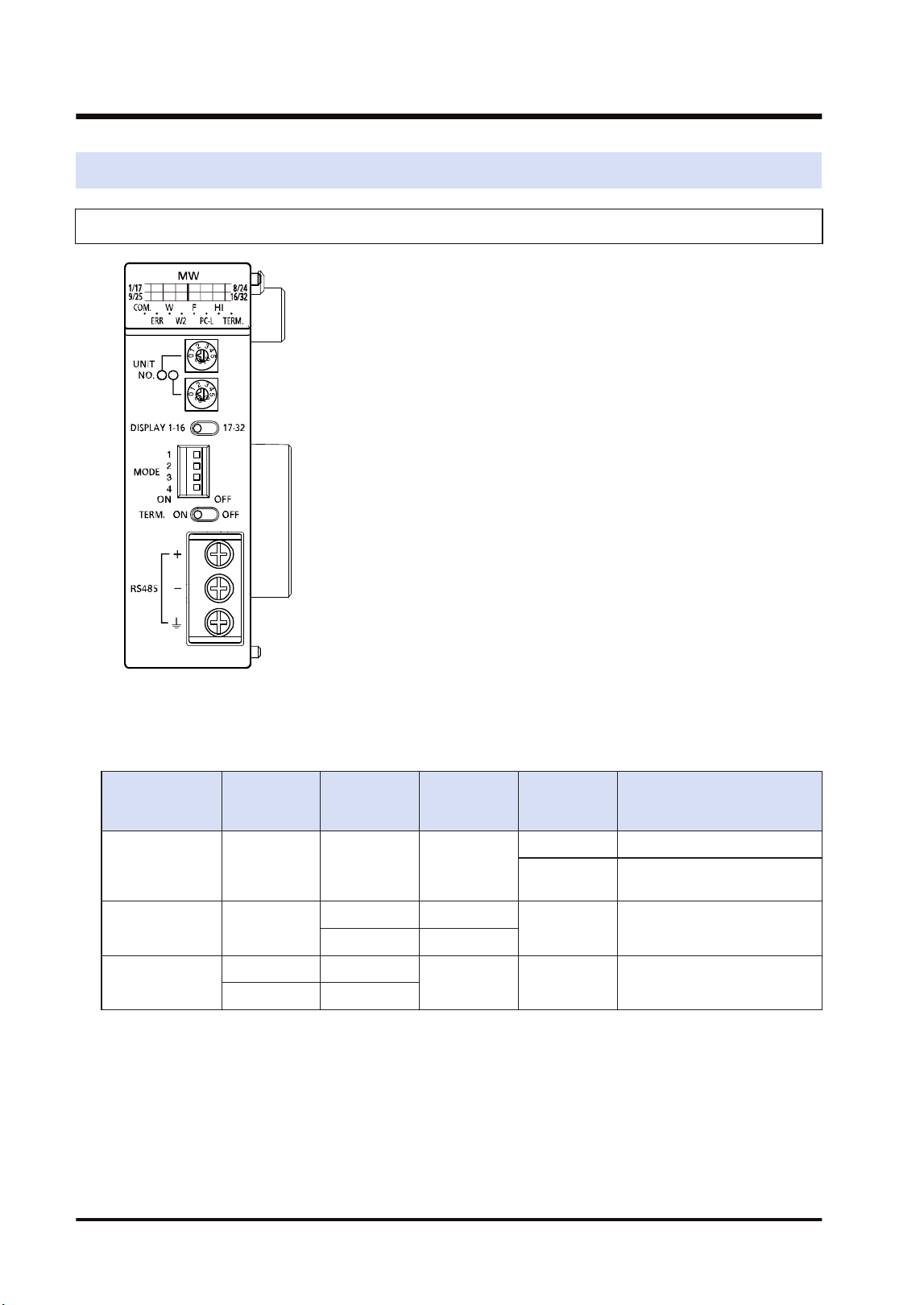
■
Overview
FP7 Multi-wire Link Unit can be used as an interface unit connected to any of the following
networks by switching with the mode setting switches of the unit.
Network Transmissio
n line
Trans-
mission
distance
Baud rate Number of
units
Main functions
MEWNET-W Twisted pair Max. 800 m 500k bit/s
Max. 16 units PLC Link
Max. 32 units
Data transmission and remote
programming
MEWNET-W2 Twisted pair
Max. 800 m 500k bit/s
Max. 32 units
PLC link, data transmission
and remote programming
Max. 1200 m 250k bit/s
MEWNET-F
Twisted pair Max. 700 m
500k bit/s Max. 32 units Remote I/O control
VCTF Max. 400 m
■
Term: Product name
To simplify the expression in the manual, the product name is abbreviated to "FP7 MW Unit".
1.1 Unit Functions and Types
1-2 WUME-FP7MW-06
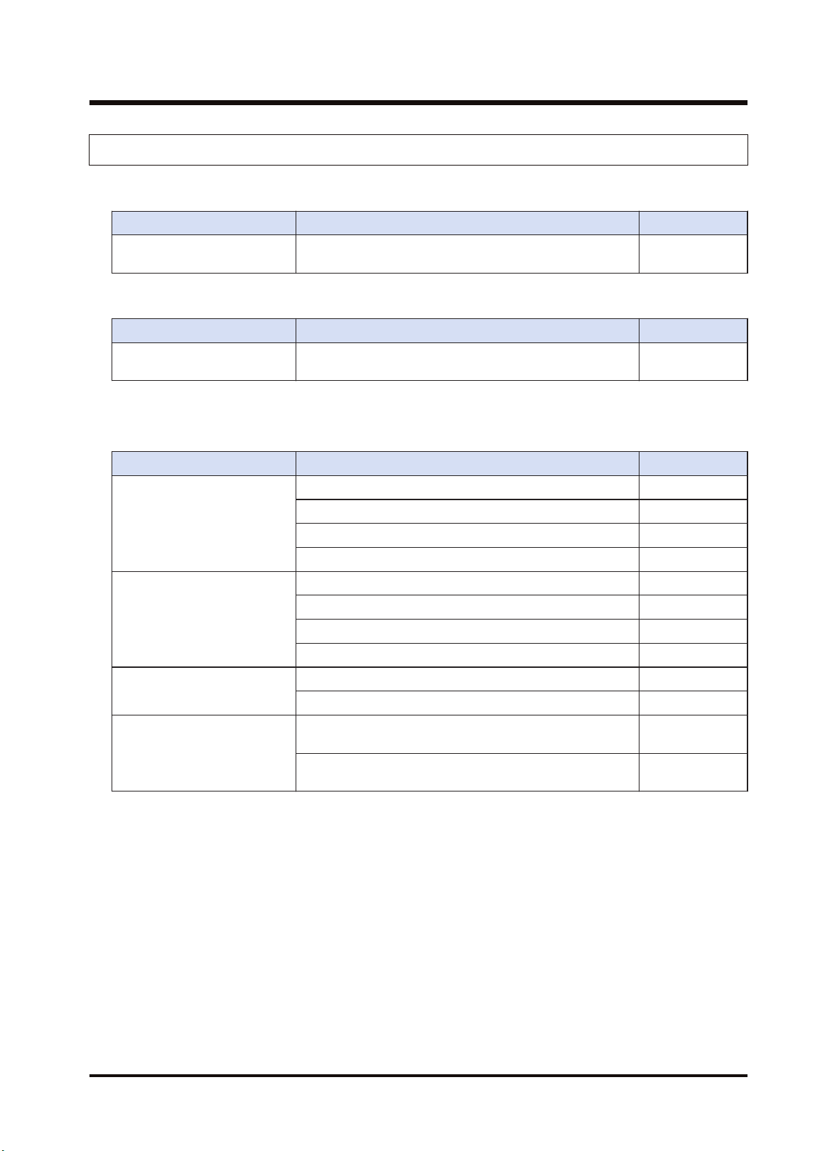
1.1.2 Unit Type
■
Unit Type
Name Specifications Product number
FP7 Multi-wire Link Unit
Unit for connecting the FP7 series to MEWNET-W,
MEWNET-W2 or MEWNET-F.
AFP7MW
■
Product related to MEWNET-W / MEWNET-W2
Item name Specifications Product number
FP2 Multi-wire Link Unit
Unit for connecting the conventional model FP2 series to
MEWNET-W, MEWNET-W2 or MEWNET-F.
AFP2720
■
Product related to MEWNET-F
The following are connectable products when using FP7 MW Unit in F mode.
Item name Specifications Product number
FP I/O terminal unit
(Primary unit)
DC input: 8 points AFP87421
DC input: 16 points AFP87422
Transistor output: 8 points AFP87423
Transistor output: 16 points AFP87424
FP I/O terminal unit
(Expansion unit)
DC input: 8 points AFP87425
DC input: 16 points AFP87426
Transistor output: 8 points AFP87427
Transistor output: 16 points AFP87428
FP I/O terminal board
(Terminal block type)
DC Input: 16 points, Relay output: 8 points AFP87432
DC input: 16 points, Transistor output: 16 points AFP87444
FP I/O terminal board
(MIL connector type)
DC input: 16 points, Transistor output: 16 points, Power
supply: 12 VDC
AFP87445
DC input: 16 points, Transistor output: 16 points, Power
supply: 24 VDC
AFP87446
1.1 Unit Functions and Types
WUME-FP7MW-06 1-3
1.2 Network Type
1.2.1 MEWNET-W / MEWNET-W2
■
Overview
● They are used to link data between PLCs connected to each network.
● The PLC link function is used to share and transmit exclusive internal relays "link relays (L)"
and data registers "link registers (LD)" between PLCs cyclically. For MEWNET-W2, "internal
relays (WR)" and "data registers (DT)" can be specified as well as "link relays (L)" and "link
registers (LD)".
● With the data transfer function, data can be transferred from a specified arbitrary source to
arbitrary destination by executing the SEND/RECV instructions with user programs.
● Also, monitoring or programming destination PLCs can also be possible via network.
● Either MEWNET-W or MEWNET-W2 can be used in the same network. It is selected by the
switch on the FP7 MW Unit.
■
Specifications
Item
Specifications
MEWNET-W MEWNET-W2
Communication
method
Token bus
Transmission system Baseband
Transmission line Twisted pair cable
Transmission distance
(Total length)
Max. 800 m Max. 800 m Max. 1200 m
Baud rate 500 kbit/s 500 kbit/s 250 kbit/s
Function / Number of
units
PLC link: Max. 16 units PLC link: Max. 32 units
data transfer: Max. 32 units data transfer: Max. 32 units
PLC link capacity
Per unit
Link relay: 1,024 points Link relay: 4,096 points
Link register: 128 words Link register: 4,096 words
Other functions Remote programming (USB port, COM port), Computer link, Hierarchy link
Interface Conforming to RS-485
RAS function Hardware self-diagnosis function
(Note 1) For MEWNET-W2, the transmission distance depends on the setting of baud rate. The baud rate is set
by the mode setting switches of the unit.
1.2 Network Type
1-4 WUME-FP7MW-06
■
Example of application
They are used when using the following Panasonic PLCs and link function.
● FP7 (Using FP7 MW Unit)
● FP2/FP2SH (Using FP2 MW Unit)
● MEWNET-W can also be connected to the conventional models FP3/FP10SH (discontinued
products) with the MEWNET-W link function.
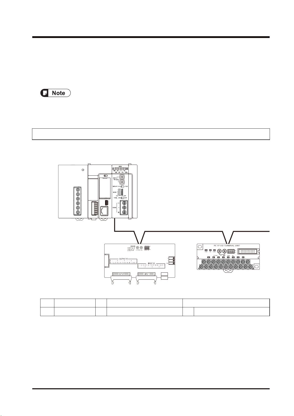
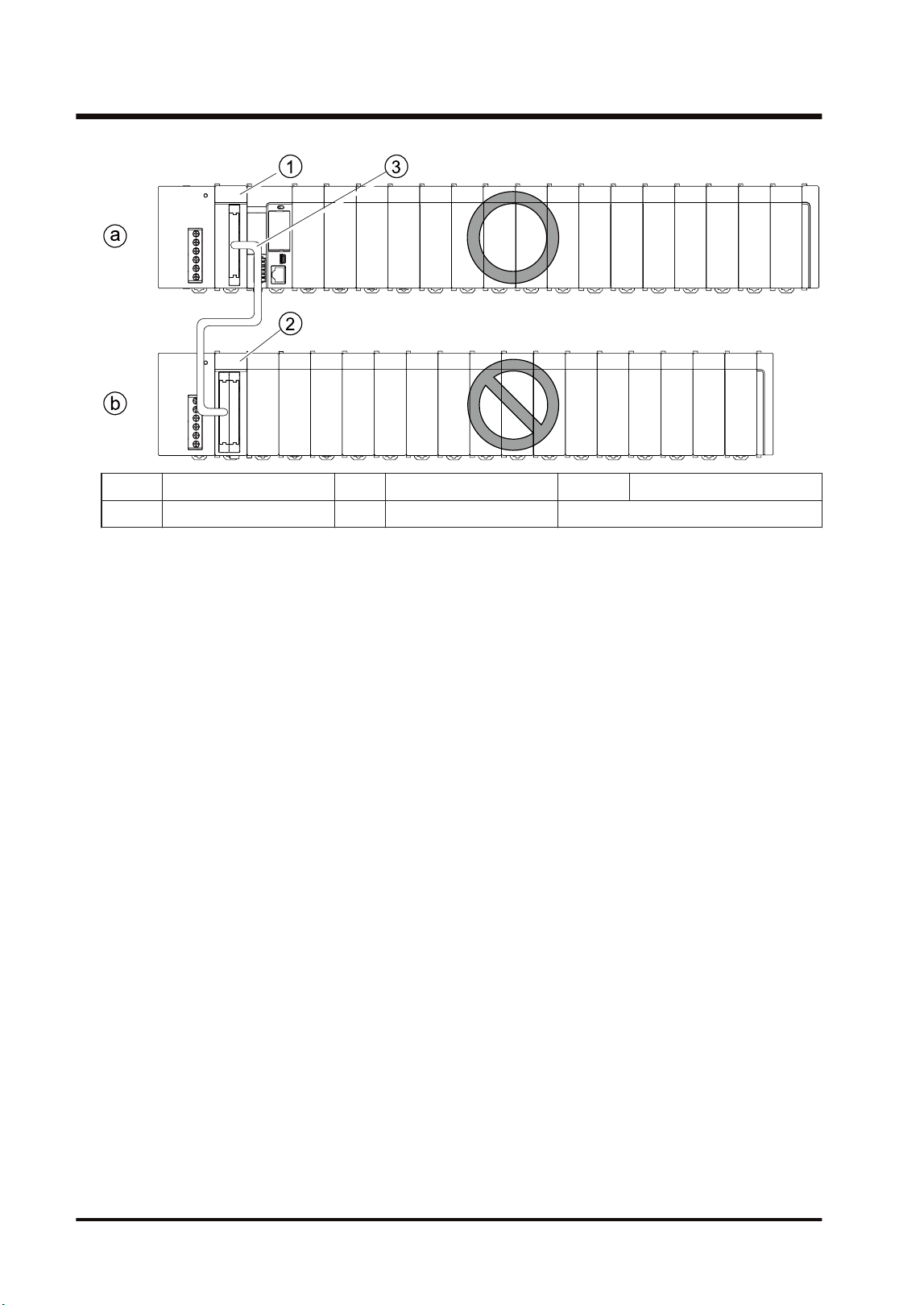
1.2.2 MEWNET-F
■
Configuration diagram
P OW E R
①
②
③
0
2
5
3
1
4
8
7
9
6
0
2
5
3
1
4
8
7
9
6
ⓐ
ⓑ
(a) Master station (1) FP7 MW Unit
(b) Slave station (2) FP I/O terminal board (3) FP I/O terminal unit
■
Overview
● A remote I/O system in which the FP7 is applied as a master unit can be established. I/O in a
remote place can be controlled via a two-wire cable so that saving wiring, reducing man-
hours and saving space is achievable.
● Up to 32 slave units, or 4096 I/O points can be controlled per FP7 MW Unit.
● The I/O of slave units can be treated as external input (X) and external output (Y) as well as
general I/O devices.
1.2 Network Type
WUME-FP7MW-06 1-5
■
Specifications
Item Specifications
Communication
method
Polling
Transmission system Baseband
Transmission line Twisted pair cable / VCTF cable
Transmission distance
(Note 1)
Max. 700 m (when using twisted pair cable)
Max. 400 m (when using VCTF cable)
Baud rate 500 kbps
No. of slave units Max. 32 units (Per master unit)
Controllable I/O points
(Note 2)
Max. 4,096 units (Per master unit)
Interface Conforming to RS-485
Transmission error
check
CRC method
(Note 1) The transmission distance varies according to the used cable and unit.
(Note 2) The number of I/O points that can be actually controlled varies according to the configuration.
■
Example of application
The remote I/O control can be performed by connecting slave units compliant with Panasonic
MEWNET-F.
● FP I/O terminal board
● FP I/O terminal unit
● It cannot be connected to FP2 Slave Unit or FP3 Slave Unit (discontinued products).
1.2 Network Type
1-6 WUME-FP7MW-06
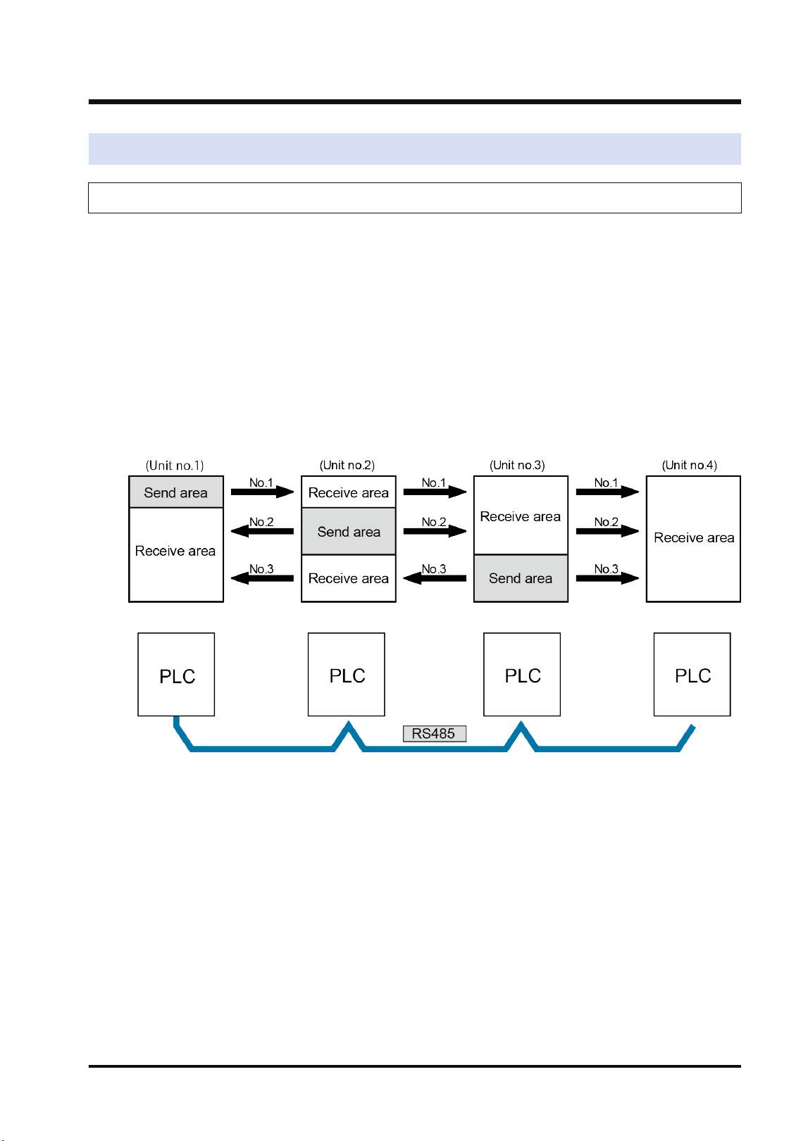
1.3 Function Overview
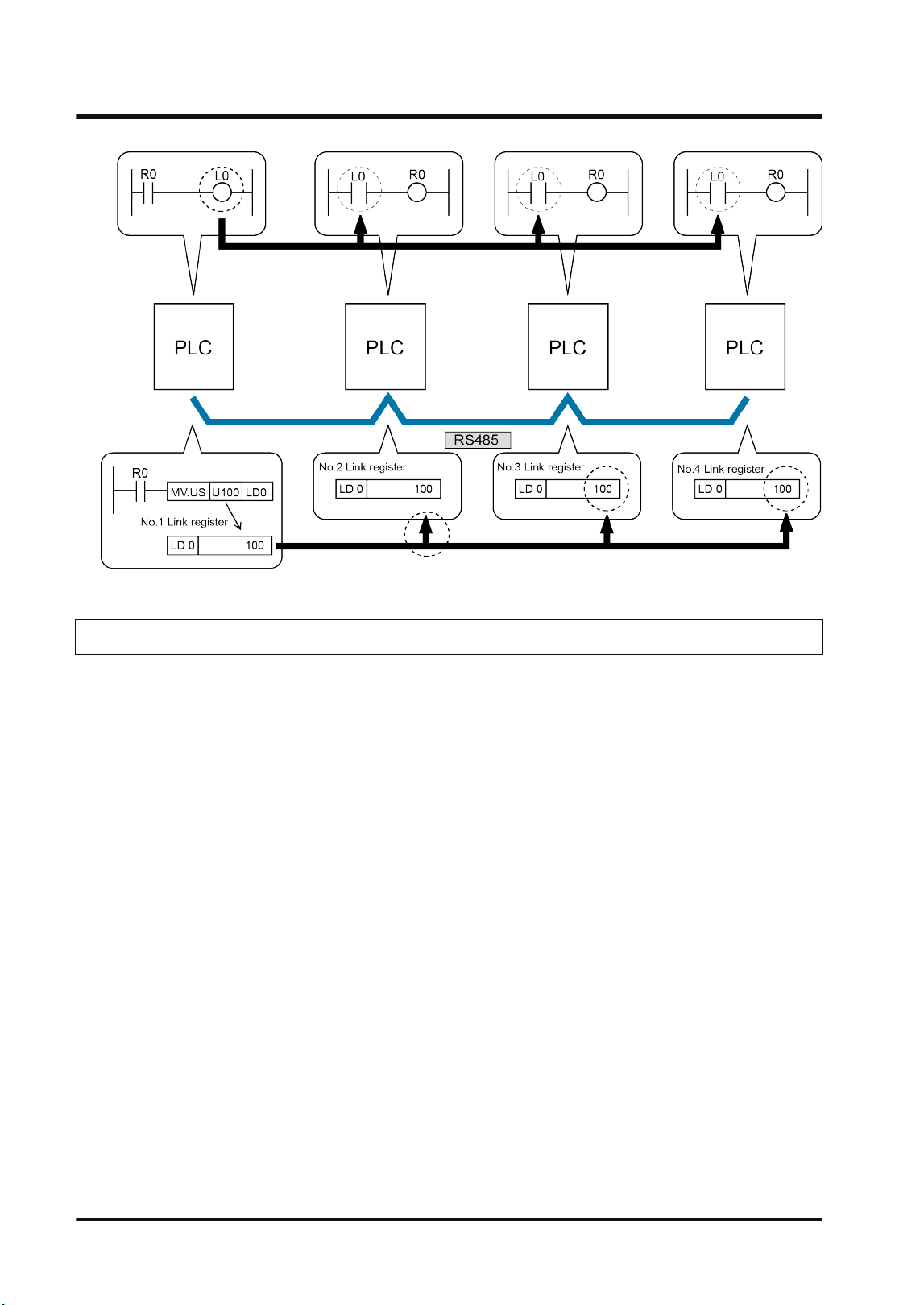
1.3.1 PLC Link (MEWNET-W / MEWNET-W2)
■
Overview of Function
● The PLC link function is a communication function which enables data sharing between
PLCs easily using link relays (L) and link registers (LD) transmitted cyclically.
● For MEWNET-F, data of link relays (1008 points) and link registers (128 words) can be
converted between max. 16 PLC units.
● For MEWNET-W2, data of link relays (4,096 points) and link registers (4,096 words) can be
converted between max. 32 PLC units. Also, internal relays (WR) and data registers (DT)
can be specified as well as link relays (L) and link registers (LD).
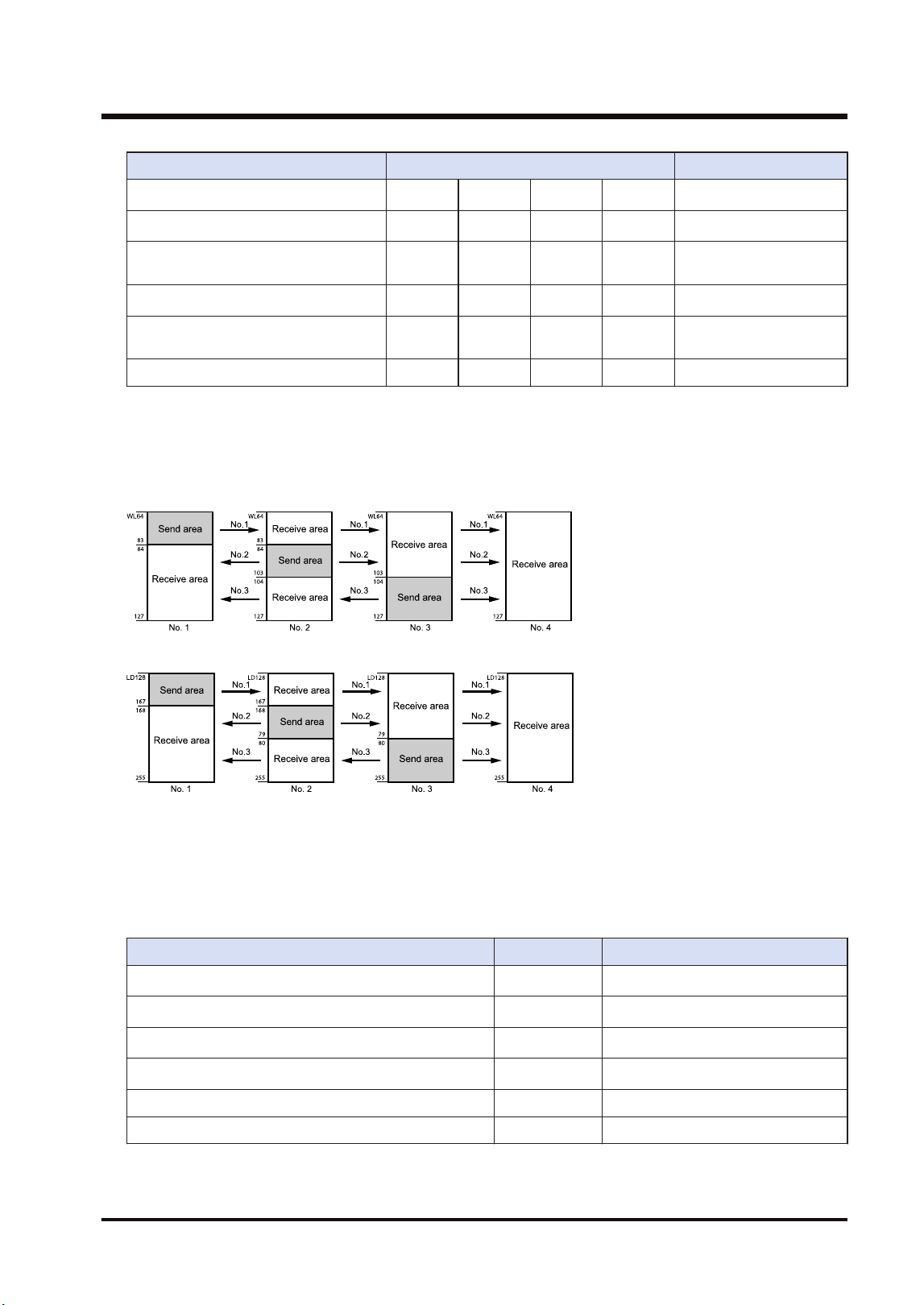
● Send area and receive area can be allocated for each PLC connected to the network. They
are set from the configuration menu of tool software.
Example of PLC link allocation
● Either one of MEWNET-W and MEWNET-W2 can be used in the same network. It is selected
by the switch on the FP7 MW Unit.
■
Role of link relays and link registers
● If the link relay contact for one PLC goes on, the same link relay also goes on in each of the
other PLCs connected to the network.
● Likewise, if the value of a link register in one PLC is changed, the values of the same link
register are changed in all PLCs on the same network.
1.3 Function Overview
WUME-FP7MW-06 1-7
1.3.2 Data Transfer (MEWNT-W / MEWNET-W2)
● With the data transfer function, data can be transferred from a specified arbitrary source to
arbitrary destination by executing the SEND/RECV instructions with user programs.
● Destination PLCs need no program for sending/receiving data.
1.3 Function Overview
1-8 WUME-FP7MW-06
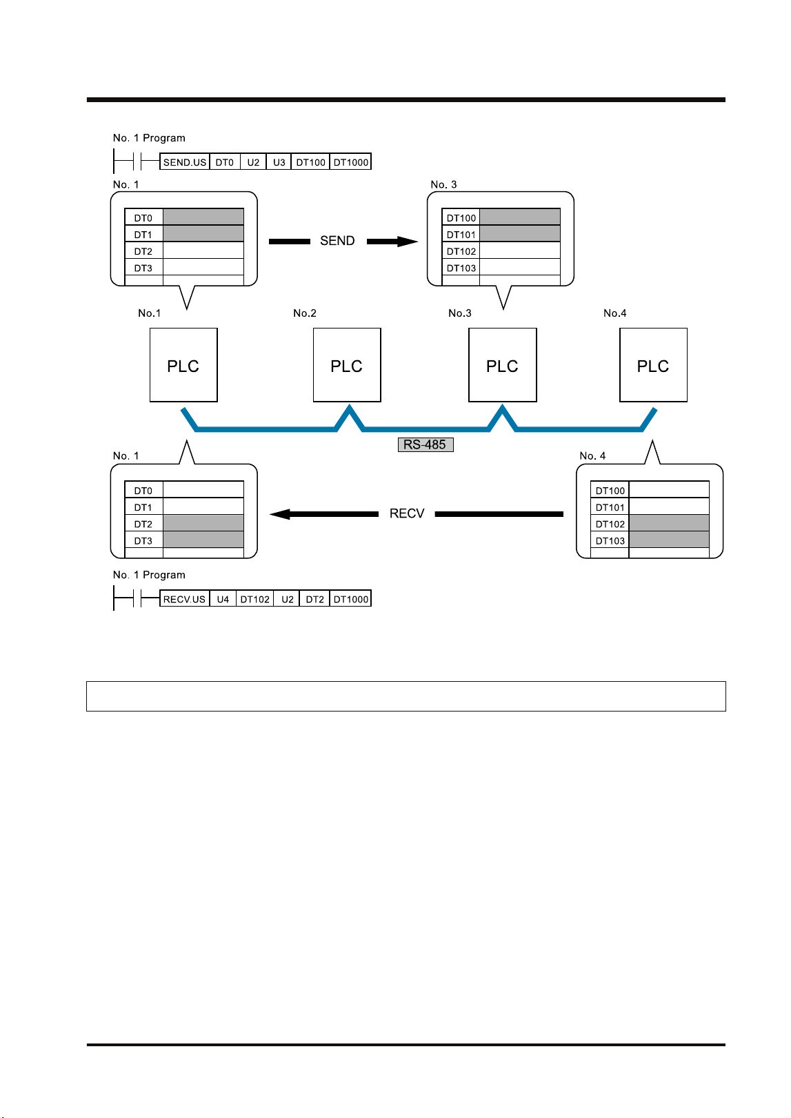
(Note 1) For the FP7 MW Unit, either one of SEND and RECV instructions can be executed.
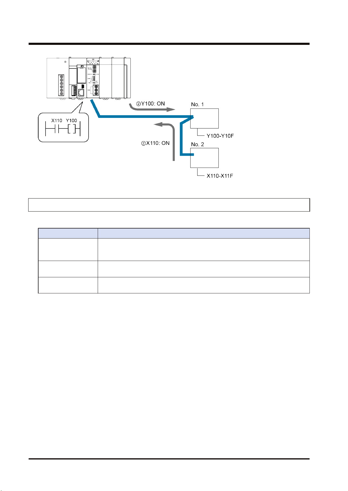
1.3.3 Remote I/O Control (MEWNET-F)
The I/O of a slave unit can be controlled on the CPU of the system (master unit) which FP7 MW
(F mode) Unit has been connected. The remote I/O control is made possible by transferring I/O
information to a slave unit according to a sequence in the CPU on the master unit.
1.3 Function Overview
WUME-FP7MW-06 1-9
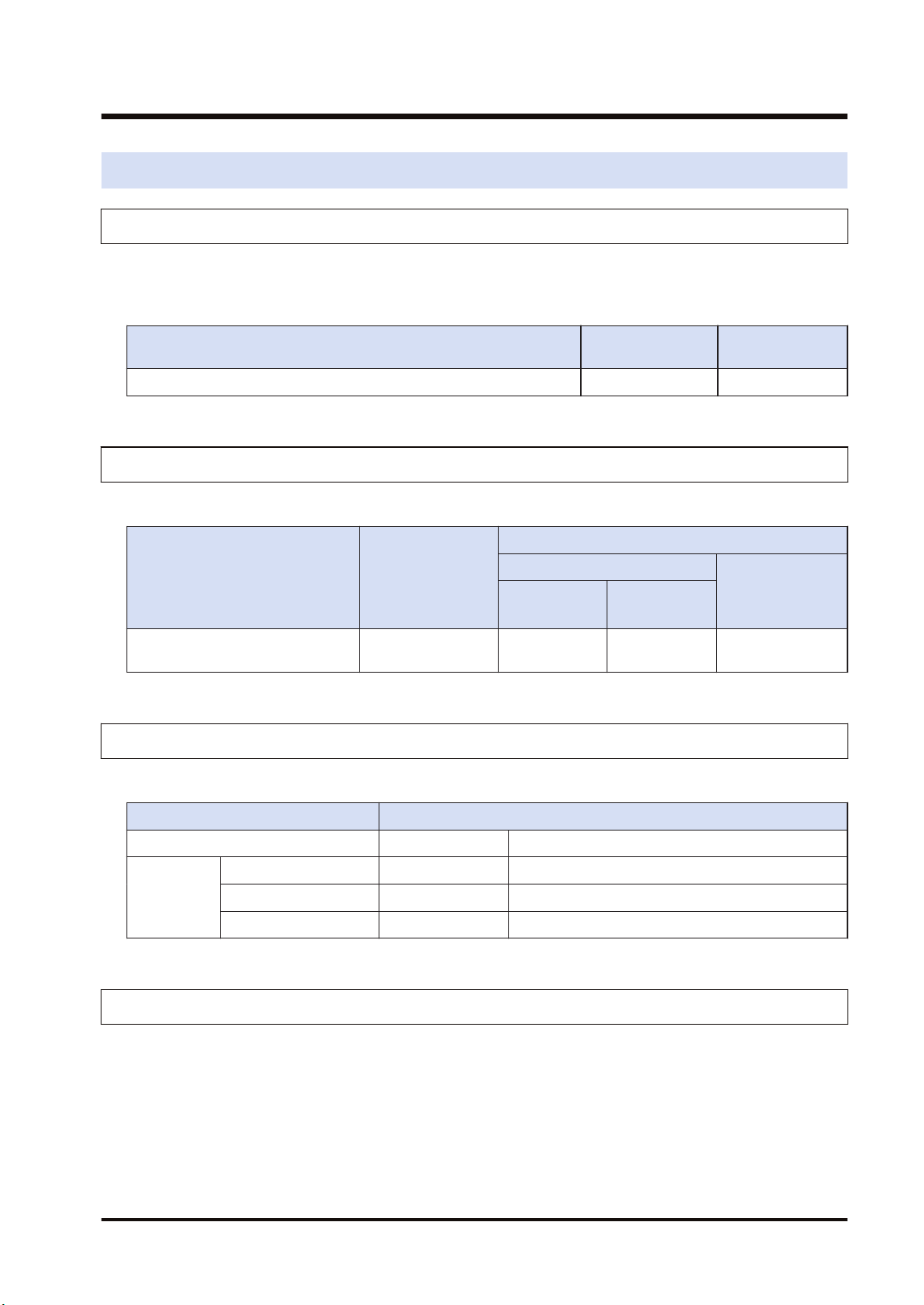
1.3.4 Other Functions (MEWNET-W / MEWNE-W2)
The functions are available besides the PLC link and data transfer functions.
Functions Overview
Remote programming
Enables PLCs in the same system connected to the network to be operated by tool
software remotely. Monitoring contacts and registers, switching the mode and rewriting
programs can be performed.
Computer Link
Enables PLCs connected to the network to be operated by MEWTOCOL commands
from a high-order PC or high-order PLC.
Hierarchy Link
Enables PLCs in different hierarchies to be operated by MEWTCOL commands
through multiple FP7 MW Units.
1.3 Function Overview
1-10 WUME-FP7MW-06
1.4 Restrictions on Combinations of Units
1.4.1 Restrictions on Power Consumption
The unit has the following internal current consumption. Make sure that the total current
consumption is within the capacity of the power supply with consideration of all other units used
in combination with this unit.
Name Product no. Consumption
current
FP7 MW Unit AFP7MW 100mA or less
1.4.2 Applicable Versions of Unit and Software
The following version of CPU unit and software are required.
Name Product no.
Applicable versions
CPU unit
FPWINGR7
CPS4*
CPS3*
CPS2*
FP7 MW Unit AFP7MW Ver.4.40 or
later
Ver.1.40 or
later
Ver.2.17 or later
1.4.3 Restrictions on Number of Installed Units and Used Functions
There are following restrictions depending on functions to be used.
Number of usable units
Total number of units Max. 6 units
MEWNET-W Max. 4 units Of which, PLC link is max. 2 units.
MEWNET-W2 Max. 4 units Of which, PLC link is max. 2 units.
MEWNET-F Max. 4 units
1.4.4 Restrictions on Installation Position
The FP7 MW Unit can be installed in the base block only. It cannot be installed in the expansion
block.
1.4 Restrictions on Combinations of Units
WUME-FP7MW-06 1-11
(a) Base block (1) Expansion master unit (3) Expansion cable
(b) Expansion block (2) Expansion Slave Unit
1.4 Restrictions on Combinations of Units
1-12 WUME-FP7MW-06
1.5 Restrictions on Communication
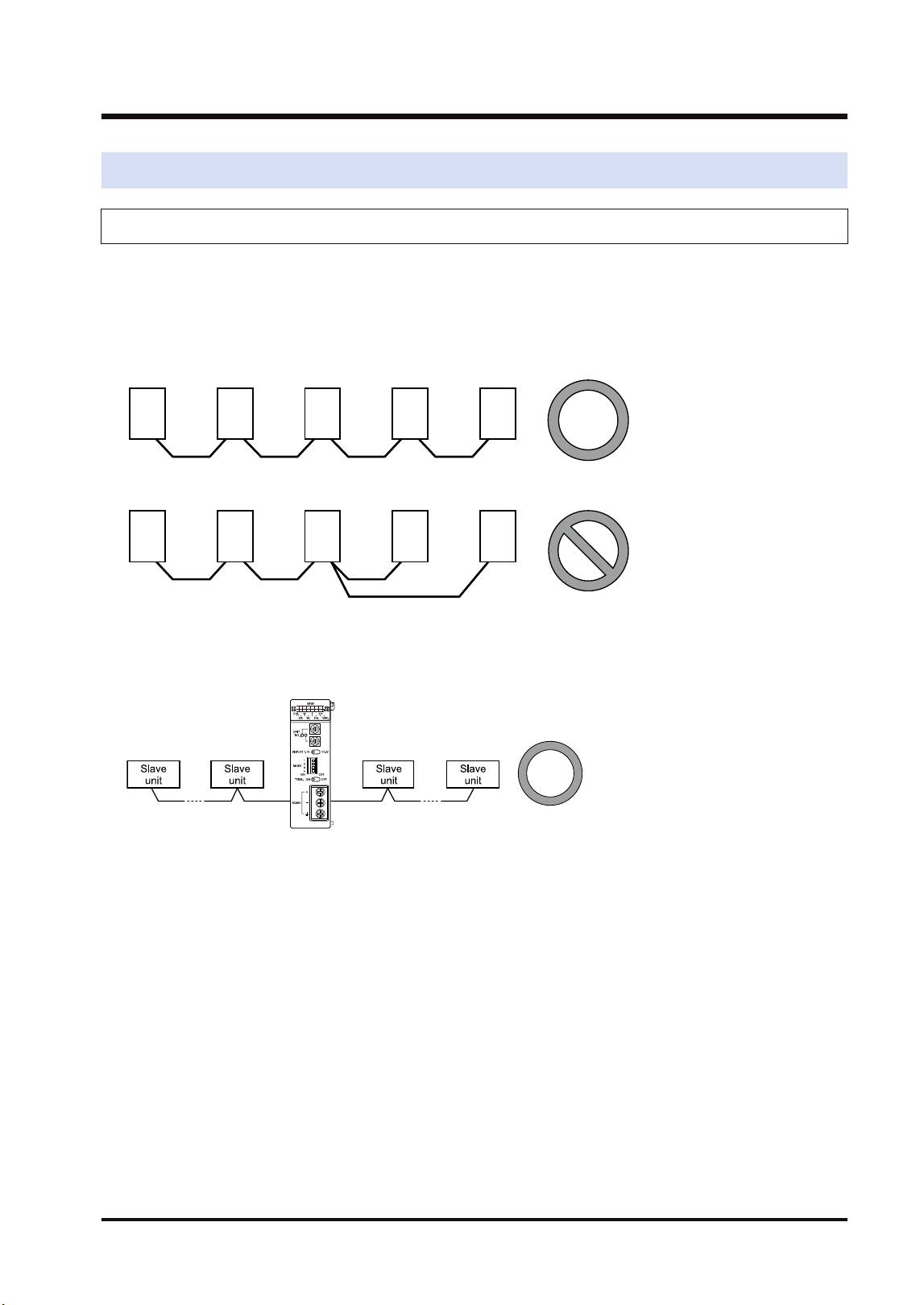
1.5.1 Restrictions on Network Configuration
■
Connection method of transmission line
Arrange the transmission line by connecting like drawing with one stroke. Never run two wires
from a single unit to two other units.
Example of correction connection
Example of wrong connection
■
Setting terminal unit
To be a terminal unit, set the switch of the unit. Also, for MEWNET-F, the FP7 MW Unit can be
placed in the middle.
1.5 Restrictions on Communication
WUME-FP7MW-06 1-13

(MEMO)
1-14 WUME-FP7MW-06

2 Names and Functions of
Parts
2.1 Names and Functions of Parts............................................................2-2
2.2 Switch Settings ...................................................................................2-3
2.3 Operation Monitor LEDs .....................................................................2-5
WUME-FP7MW-06 2-1
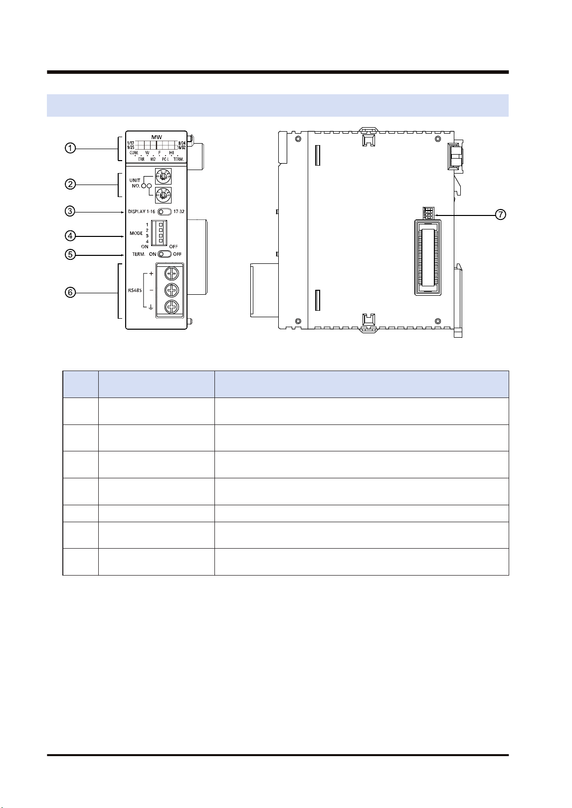
2.1 Names and Functions of Parts
■
Names and Functions of Parts
Numb
er
Name Functions
(1) Operation Monitor LEDs
Indicates the operation state of the unit such as the communication state,
error state and selected communication mode.
(2) Unit number selector
Sets the unit number of the own unit in the network. It is used in the Wor
W2 mode only.
(3)
Slave unit number display
selector
Switches the slave unit number display of the operation monitor LEDs. It
is used in the F mode only.
(4) Mode setting switch
Sets the operation mode (network type, PLC link mode, non-PLC link
mode and baud rate).
(5) Terminator setting switch Sets the terminating unit.
(6)
Connection terminal for
transmission line
For connecting the communication cables.
(7) Side switch
This switch is used for the system. Use this at the factory default (all off)
as it is.
2.1 Names and Functions of Parts
2-2 WUME-FP7MW-06
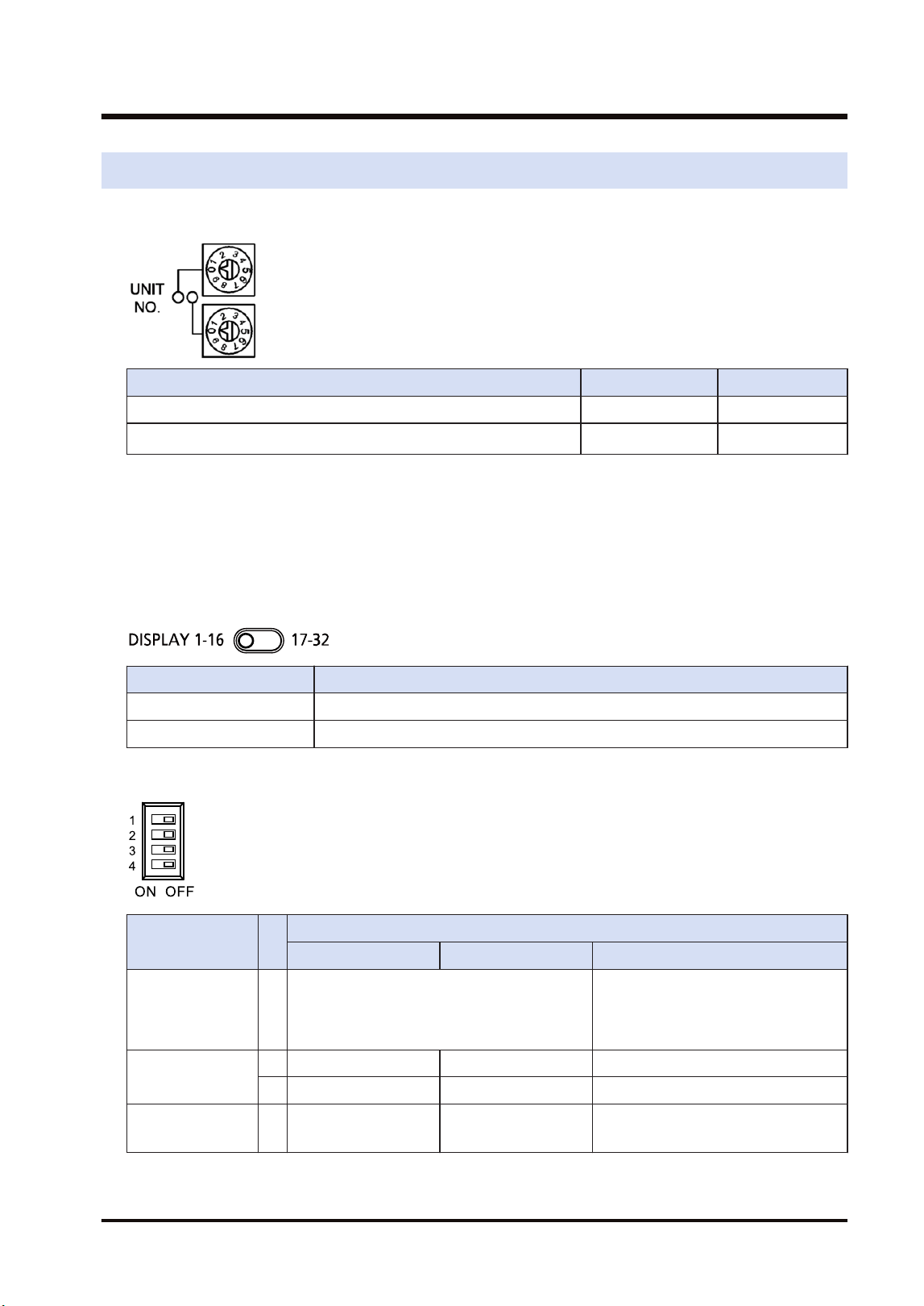
2.2 Switch Settings
■
Unit number selector (For W mode / W2 mode)
W mode W2 mode
PLC link (Corresponding unit numbers) 01 to 16 01 to 32
Data transfer (Corresponding unit numbers) 01 to 32
01 to 64
(Note 2)
(Note 1) The factory default setting is "00". When using tool software or user program to set unit numbers, set
"00".
(Note 2) It shows the range of settable unit numbers. The maximum number of units that can be actually used
is 32.
■
Slave unit number display selector (For F mode)
Switches the slave unit number display of the operation monitor LEDs.
Item Settings
1-16 Displays the connected units nos. 1 to 16.
17-32 Displays the connected units nos. 1 to 32.
■
Mode setting switch
Item
Operation
W mode W2 mode F mode
Operation mode 1
OFF: PLC link mode
ON: Non-PLC link mode
OFF: Stops communication in case of
communication error.
ON: Continues communication in case
of communication error.
Mode setting
2 OFF ON ON
3 OFF OFF ON
Baud rate 4 500 kbps fixed
OFF: 500 kbps
ON: 250 kbps
500 kbps fixed
(Note 1) Be sure the power is off when changing the switches.
(Note 2) All the switches are set to OFF at the factory.
2.2 Switch Settings
WUME-FP7MW-06 2-3
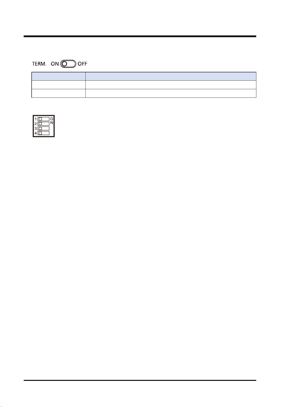
■
Terminator setting switch
Item Settings
ON Set this unit as a terminal unit.
OFF Not set this unit as a terminal unit.
■
Side switch
Do not operate the dip switch on the side of the unit. All the switches are set to OFF at the
factory.
2.2 Switch Settings
2-4 WUME-FP7MW-06
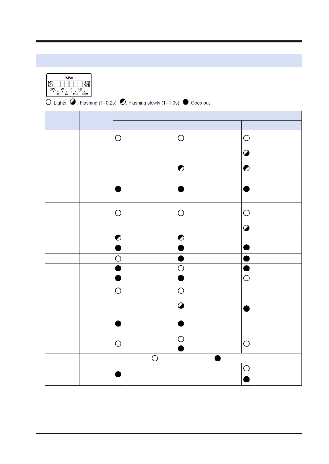
2.3 Operation Monitor LEDs
LED Description
Operation
W mode W2 mode F mode
COM.
Communicati
on status
: Communicating
(Normal)
: Communicating
(Normal)
: Waiting for
communication
: Communicating
(Normal)
: Communication
buffer overloaded
: Stop mode
transmitting
: Communication
error
(Transmission is
not available)
: Communication
error (Transmission
is not available)
: Communication
error
ERR
Hardware/
Software
error
: Out of control/
Self-diagnostic
error
: Out of control/Self-
diagnostic error
: Out of control/
Self-diagnostic
error
Setup error
: Various errors : Various errors
: Normal operation : Normal operation : Normal operation
W W mode : Lights : Goes out : Goes out
W2 W2 mode : Goes out : Lights : Goes out
F F mode : Goes out : Goes out : Lights
PC-L
PLC link
state
: PLC link
operation state
: PLC link operation
state
: Not used
: PLC link operation
impossible
: PLC link stop/
Non-PLC link
operation state
: Non-PLC link
operation state
HI Baud rate : 500 kbps fixed
: 500 kbps
: 500 kbps fixed
: 250 kbps
TERM. Terminal unit : Terminal unit : Not terminal unit
1/17-8/24
9/25-16/32
Slave unit
display
: Not used
: Connected
: Not connected
2.3 Operation Monitor LEDs
WUME-FP7MW-06 2-5

(MEMO)
2-6 WUME-FP7MW-06

3 Wiring
3.1 Applicable Cables and Solderless Terminals......................................3-2
3.1.1 Applicable cables ............................................................................. 3-2
3.1.2 Terminals.......................................................................................... 3-3
3.2 Wiring..................................................................................................3-4
3.2.1 Wiring of Transmission Line............................................................. 3-4
WUME-FP7MW-06 3-1
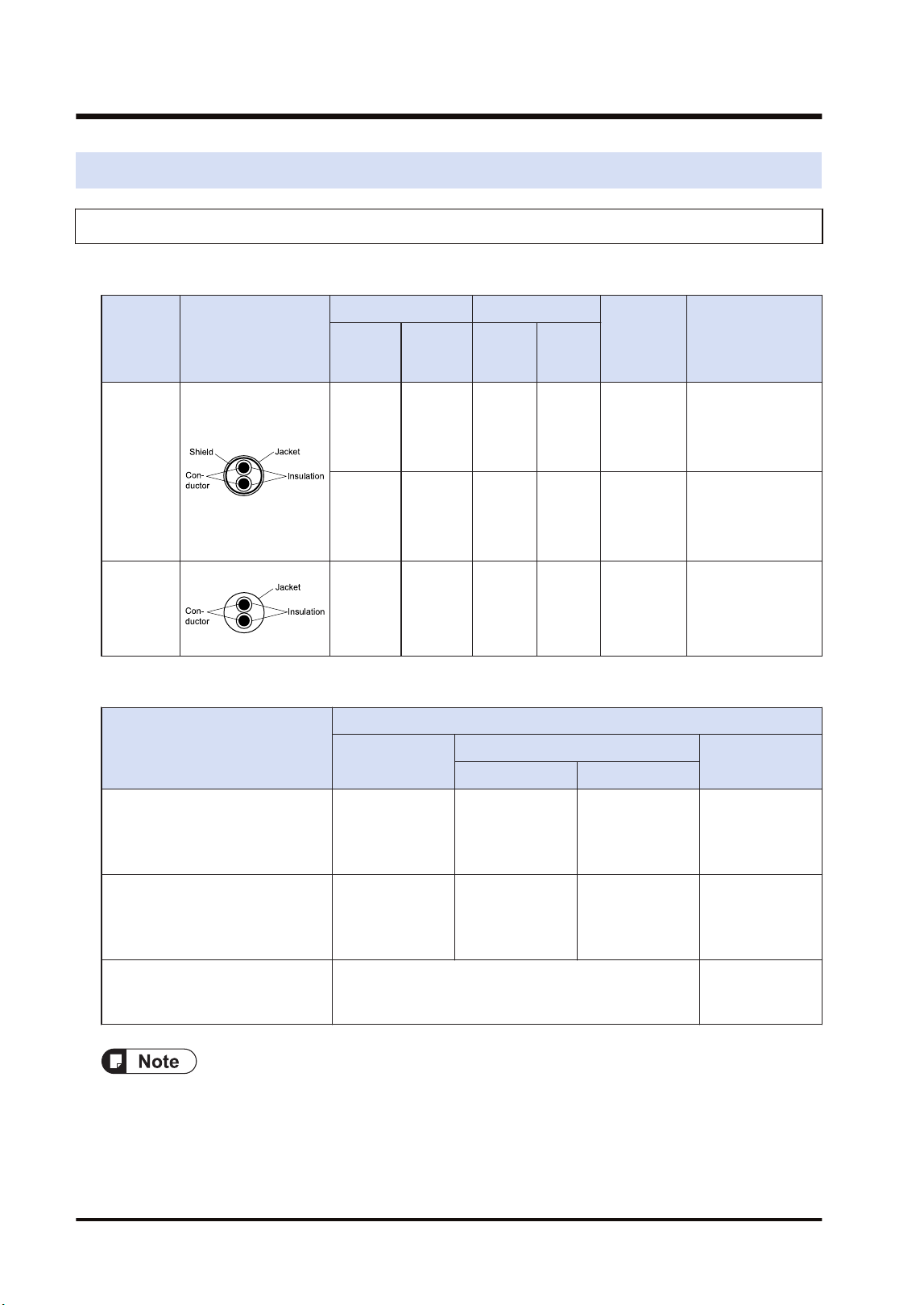
3.1 Applicable Cables and Solderless Terminals
3.1.1 Applicable cables
■
Applicable cables
Classifi-
cation
Cross-sectional
view
Conductor Insulator
Cable
diam.
Sample
appropriate cable
Size
Resistan
ce (at
20°C)
Materia
l
Thick-
ness
Shielded
twisted
pair
1.25 mm
2
(AWG16)
or more
Max.16.8
Ω/km
Polyeth
ylene
Max.
0.5 mm
Approx. 8.5
mm
Sumiden Hitachi
Cable Ltd.
KPEV-S
1.25 mm
2
× 1P
0.5 mm
2
(AWG20)
Max.
33.4
Ω/km
Polyeth
ylene
Max.
0.5 mm
Approx. 7.0
mm
Sumiden Hitachi
Cable Ltd.
KPEV-S
0.5 mm
2
× 1P
VCTF
0.75 mm
2
(AWG18)
or more
Max.
25.1
Ω/km
Polychl
orinated
bipheny
l
Max.
0.6 mm
Approx. 6.6
mm
VCTF
0.75 mm
2
× 2C
(JIS)
or equivalent
■
Applicable cables and transmission distance
Type
Transmission distance (Total length)
W mode
W2 mode
F mode
500k bit/s 250k bit/s
Shielded twisted-pair cable
Sumiden Hitachi Cable Ltd.
KPEV-S 1P × 1.25 mm2 or
equivalent
Max. 800 m Max. 800 m Max. 1200 m Max. 700 m
Shielded twisted-pair cable
Sumiden HST Cable, Ltd.
KPEV-S 1P × 0.5 mm2 or
equivalent
Max. 700 m Max. 700 m Max. 1100 m Max. 600 m
VCTF
VCTF2C×0.75mm2(JIS) or
equivalent
Not available Max. 400 m
● Configure all the wiring systems using the same type of cables. Do not mix different types of
cables.
● Polyvinyl chloride has worse electrical charactersitics than polyethylene, the total transmission
distance is shorter.
● Use shielded twisted pair cables in noisy environments.
3.1 Applicable Cables and Solderless Terminals
3-2 WUME-FP7MW-06
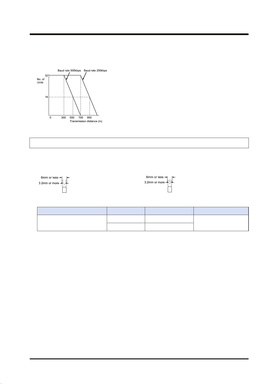
■
Example of characteristic (when using KPEV-S1Px0.5mm2 or equivalent)
When using KPEV-S1Px0.5mm2 or equivalent, reduce the transmission distance or the number
of units.
3.1.2 Terminals
M3 terminal screws are used for the terminal. The following solderless terminals are
recommended for the wiring to the terminals
<Fork type terminal> <Round type terminal>
Suitable solderless terminals
Manufacturer Shape Part No. Suitable wires
J.S.T. Mfg Co.,Ltd
Fork type 1.25-B3A
0.25 to 1.65 mm
2
Round type 1.25-MS3
Suitable wires (strand wire)
Size: AWG20-12, Rated temperature: 60/75°C
Tightening torque: 0.5–0.6 N·m (5.3 lb-in)
3.1 Applicable Cables and Solderless Terminals
WUME-FP7MW-06 3-3
3.2 Wiring
3.2.1 Wiring of Transmission Line
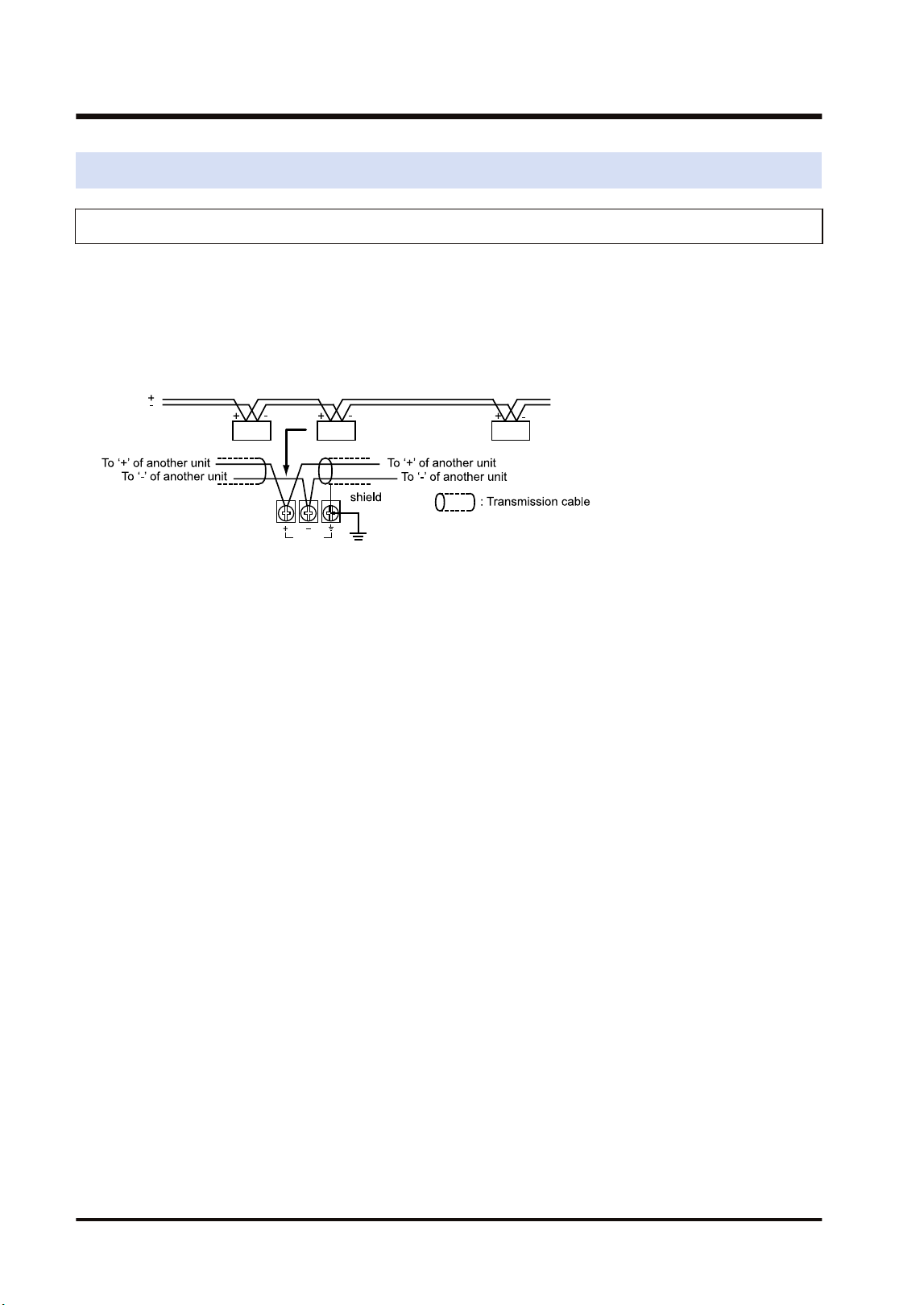
● As for transmission cables, connect RS-485 terminals, positive (+) to positive (+) and
negative (-) to negative (-).
● Connect transmission cables from one unit to the next. Never run two wires from a single unit
to two other units.
● When using a shielded transmission cable, ground the one end of the shield. Never ground
at the both ends of the cable.
3.2 Wiring
3-4 WUME-FP7MW-06

4 MEWNET-W
4.1 Overview.............................................................................................4-2
4.2 Setting the Switches of the Unit..........................................................4-3
4.3 Configuration.......................................................................................4-4
4.3.1 Registration in I/O Map .................................................................... 4-4
4.3.2 No. of Occupied I/O Points of MEWNET-W ..................................... 4-4
4.3.3 Confirmation of Slot Numbers.......................................................... 4-5
4.3.4 W Link Unit Setting Procedure......................................................... 4-6
4.3.5 W Link Unit Setting Dialog Box ........................................................ 4-7
4.3.6 Configuration Using User Programs ................................................ 4-9
4.4 PLC Link .............................................................................................4-12
4.4.1 Example of Link Area Allocation ...................................................... 4-12
4.4.2 Holding Start Number Setting .......................................................... 4-14
4.4.3 Communication State Information Copy Destination Device ........... 4-15
4.5 Data Transfer ......................................................................................4-16
4.5.1 Data Transfer from Own Unit to Destination Unit (SEND) ............... 4-16
4.5.2 Data Transfer from Destination Unit to Own Unit............................. 4-17
4.5.3 Precautions When Using Data Transfer Function............................ 4-18
WUME-FP7MW-06
4-1

4.1 Overview
The following are main steps to use the FP7 MW Unit in W mode.
Item Used tool Outline of operation
(1)
Set the switches of the
unit.
-
Select "W mode" by the mode selector switches. Set whether to
use PLC link or not.
Specify unit number. When setting it in the configuration of tool
software or user program, set it to "00".
(2)
Registration in I/O map
of the unit
FPWIN GR7
Register the unit configuration of the FP7 system in the "I/O
map" dialog box.
Confirm slot numbers specified for each instruction.
When using the data transfer function, confirm the number of
the flag to be checked when executing SEND/RECV
instructions.
(3) Unit Configuration FPWIN GR7
Specify unit number. (When selecting "00" by the unit number
selector of the unit.)
(Note 1)
Allocate link relays and link registers used for the PLC link.
(Note
2)
Set a device in which the communication state (transmission
assurance relay, operation mode relay) is copied.
(4)
Download the settings
to the unit and confirm
the operation state.
FPWIN GR7
Download "I/O map" and "unit configuration" information to the
FP7 CPU Unit.
Switch the mode to RUN mode.
Confirm the state if the process is normally performed. The
communication state and error information can be confirmed by
the communication state information copy destination device,
system relays or system data registers. Also, detailed
information can be read by PMGET instruction.
(Note 1) The unit number can be set by a user program.
(Note 2) For MEWNET-W, link relays and link registers can be allocated by user programs.
4.1 Overview
4-2 WUME-FP7MW-06
4.2 Setting the Switches of the Unit
For using the FP7 MW Unit as W link unit, the switches on the front of the unit need to be set.
■
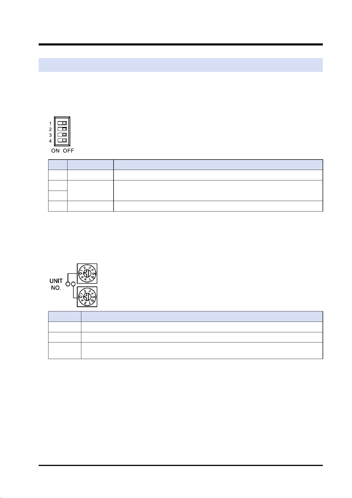
Mode setting switch
Each mode is set with the four dip switches on the front of the unit.
No. Item Range
1 Operation mode OFF: PLC link mode, ON: Non-PLC link mode
2
Mode Turn off the both 2 and 3 to activate the unit as the unit for "MEWNET-W".
3
4 Baud rate For "MEWNET-W", it is fixed at 500 kbps.
(Note 1) All the switches are set to OFF at the factory.
(Note 2) Be sure the power is off when changing the switches.
■
Unit number selector
Specify the own unit number by the two rotary switches on the front of the unit.
Range Description
01 to 16 For target unit of PLC link
01 to 32 For target unit of data transfer
00 When setting it in the configuration of the tool software or user program (PMSET/pPMSET
instruction).
(Note 1) Be sure the power is off when changing the switches.
4.2 Setting the Switches of the Unit
WUME-FP7MW-06 4-3
4.3 Configuration
4.3.1 Registration in I/O Map
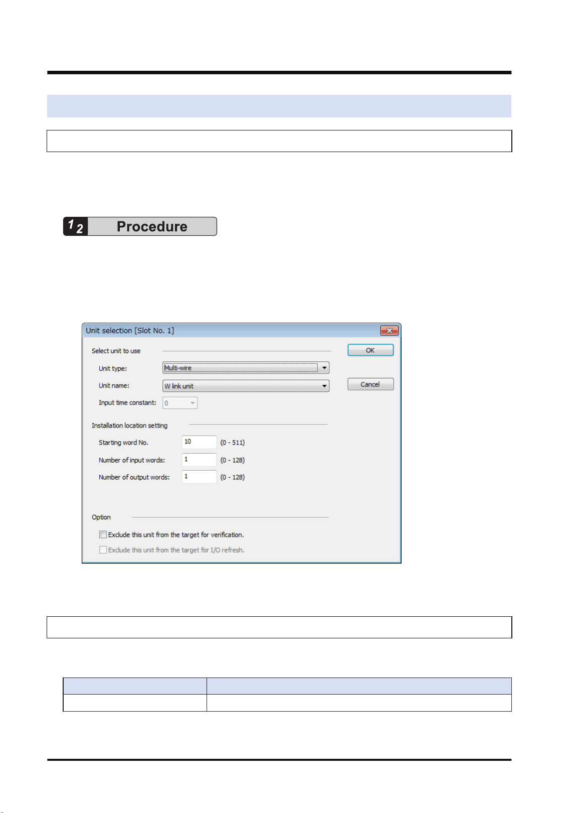
The unit is allocated to the I/O map in the tool software FPWIN GR7.
■
Allocation method
1. Select Options>FP7 Configuration>I/O map in the menu bar.
2. Double-click the target slot where the operating unit is to be inserted.
The "Unit Selection" dialog box is displayed.
3. Select "Multi-wire" and "W2 link unit" in the "Select unit to use" field.
4. Press the [[OK]] button.
4.3.2 No. of Occupied I/O Points of MEWNET-W
In W mode, the FP7 MW Unit occupies only one word. It is allocated as a flag for executing the
data transfer function (SEND/RECV instruction).
Mode No. of points
W mode 1 word / Output: 1 word (Fixed)
4.3 Configuration
4-4 WUME-FP7MW-06

■
I/O Allocation
I/O number Name Description
X100
Master communication clear
to send flag
Turns ON when the unit number of MEWNET-W has been set
and the unit is in RUN mode.
Y100
Master communication send
active flag
Turns ON during sending data based on the SEND/RECV
instruction. Turns OFF when the ED instruction is executed
after the completion of the response receive processing.
(Note 1) Each contact in the table above is used for reading the operation status. Do not write them using user
programs.
(Note 2) The above I/O numbers are those for the base word number 10.
4.3.3 Confirmation of Slot Numbers
Slot numbers are decided by registering units in the I/O map. Slot numbers are used when
reading or writing the values of unit memories by user programs. They are also used when
performing the data monitoring on FPWIN GR7.
■
Slot No.
Slot numbers are decided by each installation position of units. They are counted from the unit
closest to the CPU unit.
■
Display on the I/O map of FPWIN GR7
Slot numbers can be confirmed in the "I/O map" dialog box of FPWIN GR7.
■
Using by user programs
The user program below is that for specifying the slot number.
PMGET DT0U2
R100
UNITSEL U0U1
S1 S2
S D
4.3 Configuration
WUME-FP7MW-06 4-5
4.3.4 W Link Unit Setting Procedure
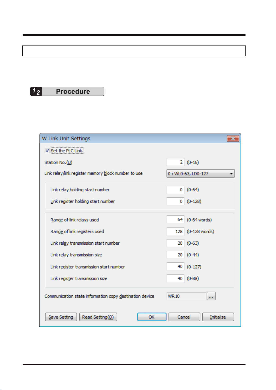
Link relays and link registers are set in the "W Link Unit Settings" dialog box of FPWIN GR7.
The following procedure describes the case that "W link unit" has been already registered in the
"I/O map" dialog box.
1. Select Options>FP7 Configuration>I/O map in the menu bar.
The "I/O map" dialog box is displayed.
2. Select the slot where the W link unit has been selected, and press the [Advanced] button.
The "W Link Unit Settings" dialog box is displayed.
3. Check "Set the PLC Link" and set the unit number.
For setting the PLC link in the configuration (the above dialog box), check the checkbox.
For setting the PLC link in the configuration (the above dialog box), uncheck the checkbox.
4.3 Configuration
4-6 WUME-FP7MW-06
4. For making the configuration of PLC link, set each item relating to link relays and link
registers.
5. Press the [[OK]] button.
The window returns to the "I/O map" dialog box.
6. Press the [[OK]] button.
It returns to the edit window of FPWIN GR7. These settings will be downloaded to the CPU
unit together with programs and other configuration information, and will be effective in
RUN mode.
● Assign the own unit number within the following ranges.
PLC link target unit numbers: 1 to 16
Data transfer target unit numbers: 1 to 32
● Press the [Save Setting] button in the "W Link Unit" Settings dialog box to save configuration
data (extension: .fp7mww) for the W link unit. The configuration data can also be used for other
projects.
● For the details of the setting items of "W Link Unit" Settings dialog box, refer to the next page.
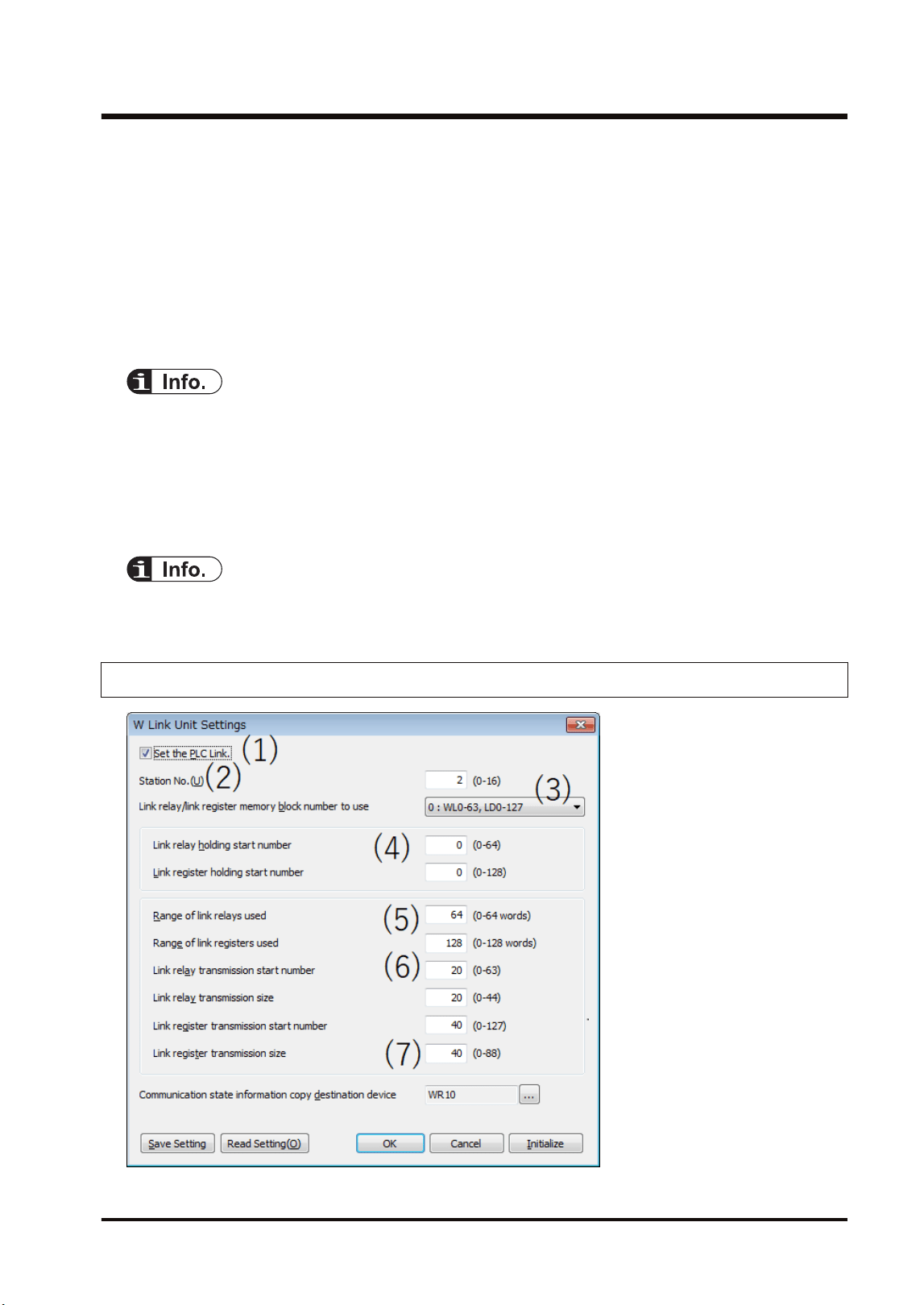
4.3.5 W Link Unit Setting Dialog Box
4.3 Configuration
WUME-FP7MW-06 4-7

■
Setting item
No. Item Range Remarks
(1) Set the PLC Link.
For setting the PLC link in the configuration (the above
dialog box), check the checkbox. For setting the PLC link
in the configuration (the above dialog box), uncheck the
checkbox.
(2) Unit no.
Specify a unit number for the own unit.
PLC link target unit numbers: 1 to 16
Data transfer target unit numbers: 1 to 32
When setting it using a user program (PMSET/pPMSET
instruction), specify "0".
(3)
Link relay/link register memory
block number to use
Select the range of device numbers.
0: WL0-WL63, LD0-LD127
1: WL64-WL127, LD128-LD255
2: WL128-WL191, LD256-LD383
3: WL192-WL255, LD384-LD511
4: WL256-WL319, LD512-LD639
5: WL320-WL383, LD640-LD767
6: WL384-WL447, LD768-LD895
7: WL448-WL511, LD896-LD1023
(4)
Link relay holding start no.
Link register holding start no.
Set the starting word number of a device used as hold
type. The holding start number is specified as a relative
value from the beginning of the memory block.
For link relays: 0-64
For link registers: 0 to 128
Example 1) When specifying 0, the area in the selected
range is hold type.
Example 2) When specifying the maximum value, the
area in the selected range is non-hold type.
(5)
Range of link relays used Set the number of words of a device used as link relay
and link register. Link relays and link registers that are
not used can be used as functions similar to internal
relays and data registers.
Range of link registers used
(6)
Starting number for link relay
transmission
Specify the send area of link relays and link registers in
word units. The transmission start number is specified as
a relative value from the beginning of the memory block.
Example) When selecting the memory block number "1:
WL64-WL127, LD128-LD255", WL84- will be the send
area by setting the link relay transmission start number to
"20".
Link relay transmission size
Starting number for link register
transmission
Link register transmission size
(7)
Communication State
Information Copy Destination
Device
Specify the starting device of the 2-word area in which
the transmission assurance relay (1 word: for 16 units)
and operation mode relay (1 word: for 16 units) of
MEWNET-W are copied.
4.3 Configuration
4-8 WUME-FP7MW-06
● Assign the own unit number within the following ranges.
PLC link target unit numbers: 1 to 16
Data transfer target unit numbers: 1 to 32
● For FP7, the ranges of link relays and link registers that can be specified are different from
those for conventional models. Link relays and link registers can be allocated to different blocks
in such a case as using memory blocks (0: WL0-WL63, LD0-LD127, 1: WL64-WL127, LD128-
LD255) by the system using MEWNET-W0. It is recommended to allocate the same numbers
(0: WL0-WL63, LD0-LD127, 1: WL64-WL127, LD128-LD255) when performing the PLC link
with conventional models such as FP2SH series.
● For information on configuration examples of link relays and link registers, refer to "4.4 PLC
Link".
4.3.6 Configuration Using User Programs
In MEWNET-W, unit numbers, link relays and link registers can be allocated by the user
programs (PMSET/pPMSET instruction). The unit number selector on the front panel of the unit
needs to be set to "00".
■
Sample program
This sample program shows the allocation of unit number, link relay and link register for the FP7
MW Unit (W Link Unit) installed in the slot number 1.
4.3 Configuration
WUME-FP7MW-06 4-9
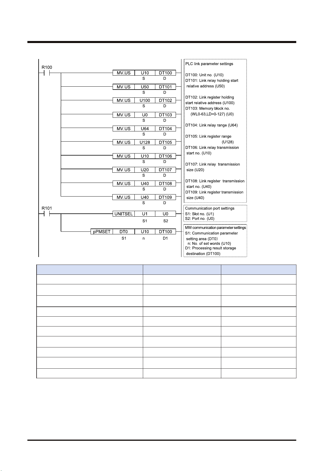
Item Setting example Remarks
Unit no. U10
Link relay holding start relative address 50
(Note 1)
Link register holding start relative address U100
(Note 2)
Memory block number 0 (WL0-63, LD=0-127)
Range of link relays used 64
Range of link registers used 128
Starting number for link relay transmission U10
(Note 1)
Link relay transmission size 20
Starting number for link register transmission 40
(Note 2)
Link register transmission size 40
(Note 1) The link relay transmission start number is specified as a relative value from the beginning of the
device specified by "Memory block number".
(Note 2) The link register transmission start number is specified as a relative value from the beginning of the
device specified by "Memory block number".
4.3 Configuration
4-10 WUME-FP7MW-06

● For the FP7 MW Unit (W mode), link areas as well as unit numbers can be allocated by user
programs.
4.3 Configuration
WUME-FP7MW-06 4-11
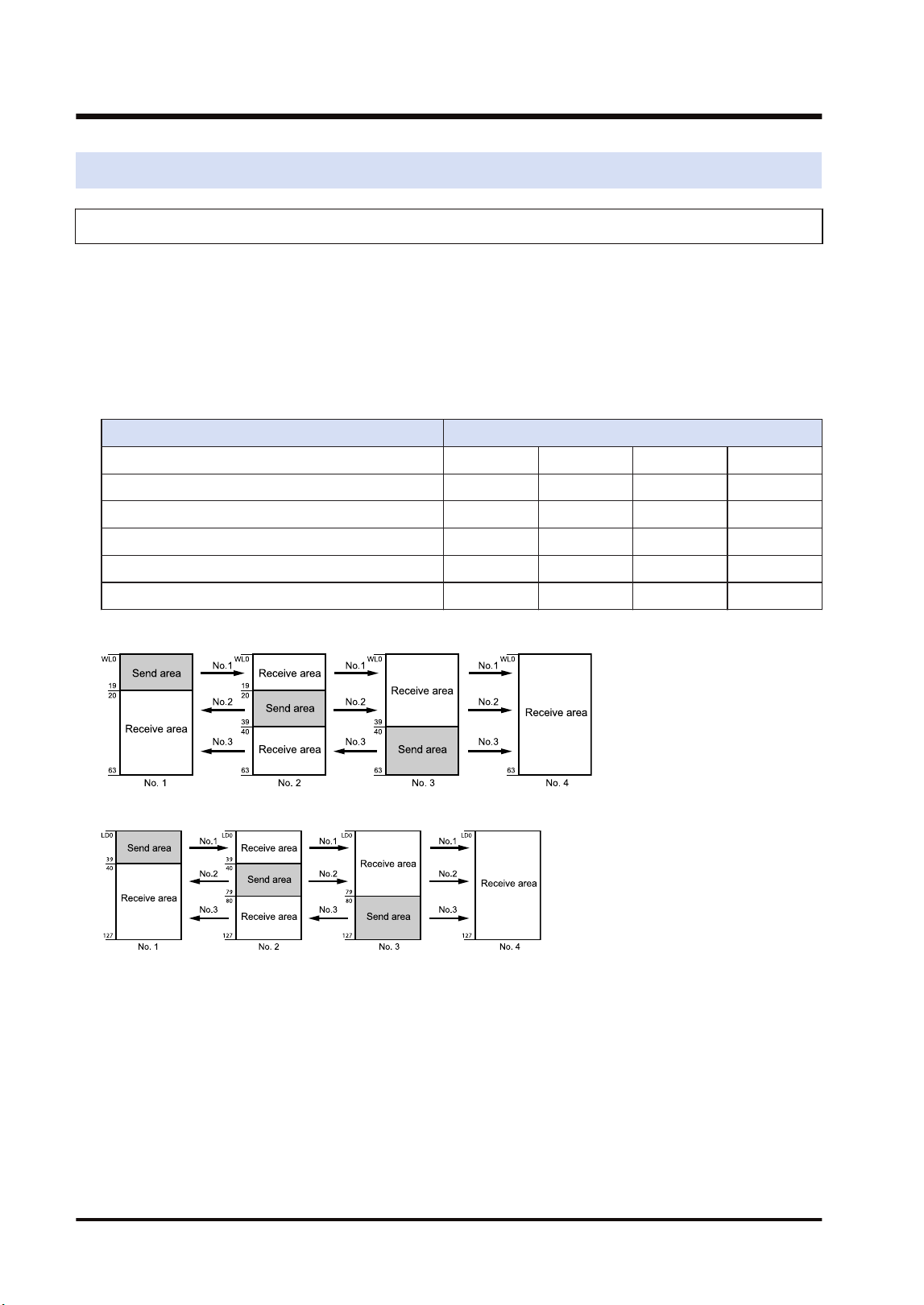
4.4 PLC Link
4.4.1 Example of Link Area Allocation
Link relays and link registers used for the PLC link are allocated to the configuration of the FP7
MW Unit.
■
Link Area Allocation: Example 1
● The PLC link area is divided into the send area and receive area for each unit and used.
● The link relays and link registers are sent from the send area to the receive area of a
different PLC.
Item Each unit setting
Range of link relays used 64 64 64 64
Range of link registers used 128 128 128 128
Starting number for link relay transmission 0 20 40 0
Link relay transmission size 20 20 24 0
Starting number for link register transmission 0 40 80 0
Link register transmission size 40 40 48 0
- Link relay allocation
- Link register allocation
● When link areas are allocated as shown above, the send area no. 1 is sent to the receive
areas nos.2, 3 and 4. Also, the receive area no. 1 receives data from the send areas nos. 2
and 3.
● No.4 is allocated as a receive area only, and receives data from nos. 1, 2 and 3.
■
Link area allocation: Example 2 (WL64-127, LD128-255)
● Select the memory block numbers (1: WL64-127, LD128-255) of used link relay and link
register.
● The PLC link area is divided into the send area and receive area for each unit and used.
● The link relays and link registers are sent from the send area to the receive area of a
different PLC.
4.4 PLC Link
4-12 WUME-FP7MW-06
Item Each unit setting
Range of link relays used 64 64 64 64
(Note 1)
Range of link registers used 128 128 128 128
(Note 2)
Starting number for link relay
transmission
0 20 40 0
(Note 1)
Link relay transmission size 20 20 24 0
(Note 2)
Starting number for link register
transmission
0 40 80 0
Link register transmission size 40 40 48 0
(Note 1) The link relay transmission start number is specified as a relative value from the beginning of the
device specified by "Memory block number".
(Note 2) The link register transmission start number is specified as a relative value from the beginning of the
device specified by "Memory block number".
- Link relay allocation
- Link register allocation
■
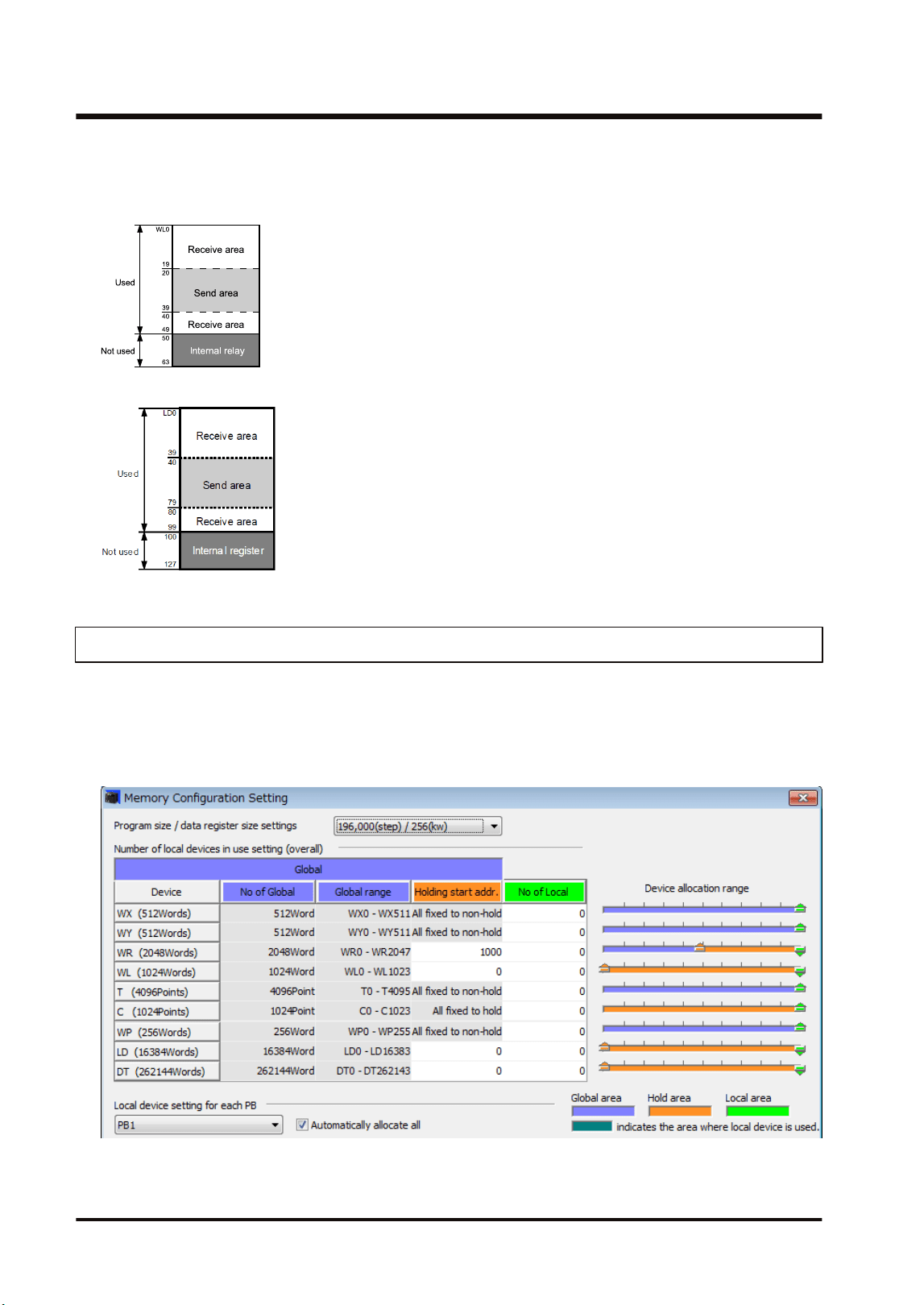
Link area allocation: Example 3 (Partial use of link area)
● In the link area, link relays (1024 points) and link registers (128 words) can be used. This
does not mean, however, that it is necessary to reserve the entire area.
● Parts of the area which have not been reserved can be used as internal relays or internal
registers.
Item Set value
Range of link relays used 50
(Note 1)
Range of link registers used U100
(Note 2)
Starting number for link relay transmission 20
(Note 1)
Link relay transmission size 20
(Note 2)
Starting number for link register transmission 40
Link register transmission size 40
(Note 1) The link relay transmission start number is specified as a relative value from the beginning of the
device specified by "Memory block number".
4.4 PLC Link
WUME-FP7MW-06 4-13
(Note 2) The link register transmission start number is specified as a relative value from the beginning of the
device specified by "Memory block number".
- Link relay allocation
- Link register allocation
4.4.2 Holding Start Number Setting
● To enable the setting of the "holding start number" specified in the "W Link Unit Settings"
dialog box, the device "L" or "LD" should be set to the hold area in the "Memory
Configuration Setting" dialog box for the CPU unit.
● Select Options>FP7 Configuration>Memory Configuration in the menu bar of FPWIN
GR7.
4.4 PLC Link
4-14 WUME-FP7MW-06
4.4.3 Communication State Information Copy Destination Device
The information indicating the communication state of the unit can be monitored as the
transmission assurance relay and operation mode relay. The information storage destination is
specified in the "W Link Unit Settings" dialog box.
■
Communication state information
Storage
location
Item Description
[D]
PLC link transmission assurance
relays
bit0 to bit15: Unit no. 1 to unit no. 16
OFF: Normal
ON: Unit which performs PLC link
[D+1] PLC link operation mode relay
bit0 to bit15: Unit no. 1 to unit no. 16
OFF: PROG mode
ON: RUN mode
(Note 1) The storage destination [D] to [D+1] is determined by the device specified for "Communication state
information copy destination device" in the "W Link Unit Settings" dialog box. When selecting WR10,
they are allocated as follows.
PLC link transmission assurance relay: R100 to R10F, PLC link operation mode relay: R110 to R11F
● The communication state information can also be read by a user program (PMGET
instruction).Refer to "9.1.3 PMGET Instruction (For MEWNET-W)".
4.4 PLC Link
WUME-FP7MW-06 4-15
4.5 Data Transfer
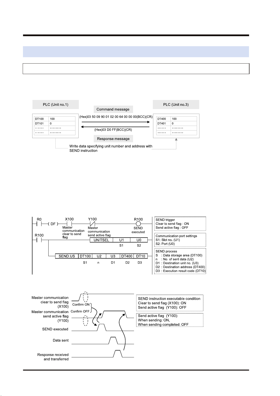
4.5.1 Data Transfer from Own Unit to Destination Unit (SEND)
In MEWNET-W, data can be transferred by specifying an arbitrary unit number or device in a
user program. The PLC generates a message according to the protocol automatically.
Destination PLCs need no program for sending/receiving data.
■
Sample Program (Word transmission)
● Transfers the content of the device for operation (DT100 to DT101) of the own unit to the
device for operation (DT400 to DT401) of a destination unit via the MW Unit installed in the
slot 1.
● The SEND instruction is executed by specifying the starting address (DT100) and number of
DATA (U2) of the source unit and the unit number (U3) and starting address (DT400) of the
destination unit.
● The execution result code is set in DT10 of the own unit.
■
Time chart
4.5 Data Transfer
4-16 WUME-FP7MW-06
■
I/O Allocation
I/O number Name Description
X100
Master communication clear
to send flag
Turns ON when the unit number of MEWNET-W has been set
and the unit is in RUN mode.
Y100
Master communication send
active flag
Turns ON during sending data based on the SEND/RECV
instruction. Turns OFF when the ED instruction is executed
after the completion of the response receive processing.
(Note 1) Each contact in the table above is used for reading the operation status. Do not write them using user
programs.
(Note 2) The above I/O numbers are those for the base word number 10.
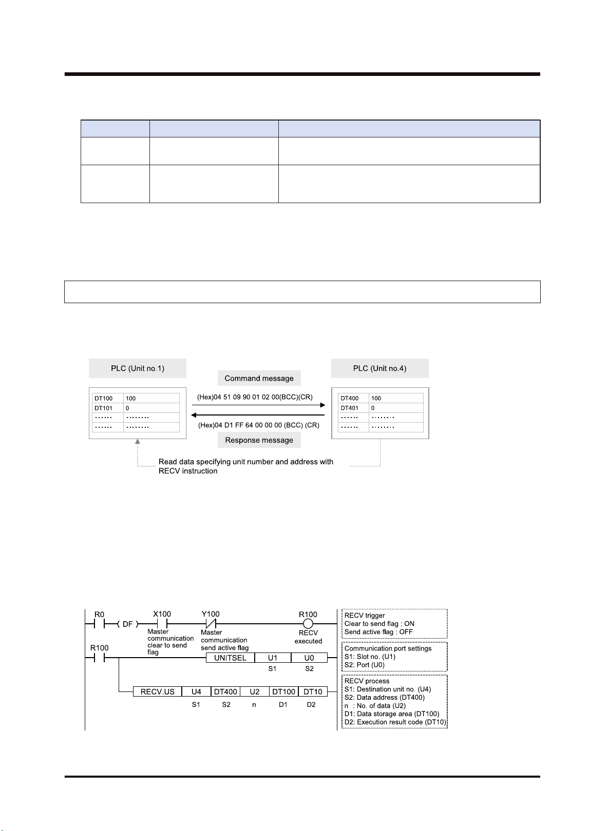
4.5.2 Data Transfer from Destination Unit to Own Unit
In MEWNET-W, data can be transferred by specifying an arbitrary unit number or device in a
user program. The PLC generates a message according to the protocol automatically.
Destination PLCs need no program for sending/receiving data.
■
Sample Program (Word reception)
● Reads and transfers the content of the device for operation (DT400 to DT401) of a
destination unit to the device for operation (DT100 to DT101) of the own unit via the MW Unit
installed in the slot 1.
● The RECV instruction is executed by specifying the unit number (U4), starting address
(DT400) and number of data (U2) of the destination unit and the starting address (DT100) of
the own unit.
● The execution result code is set in DT10 of the own unit.
4.5 Data Transfer
WUME-FP7MW-06 4-17
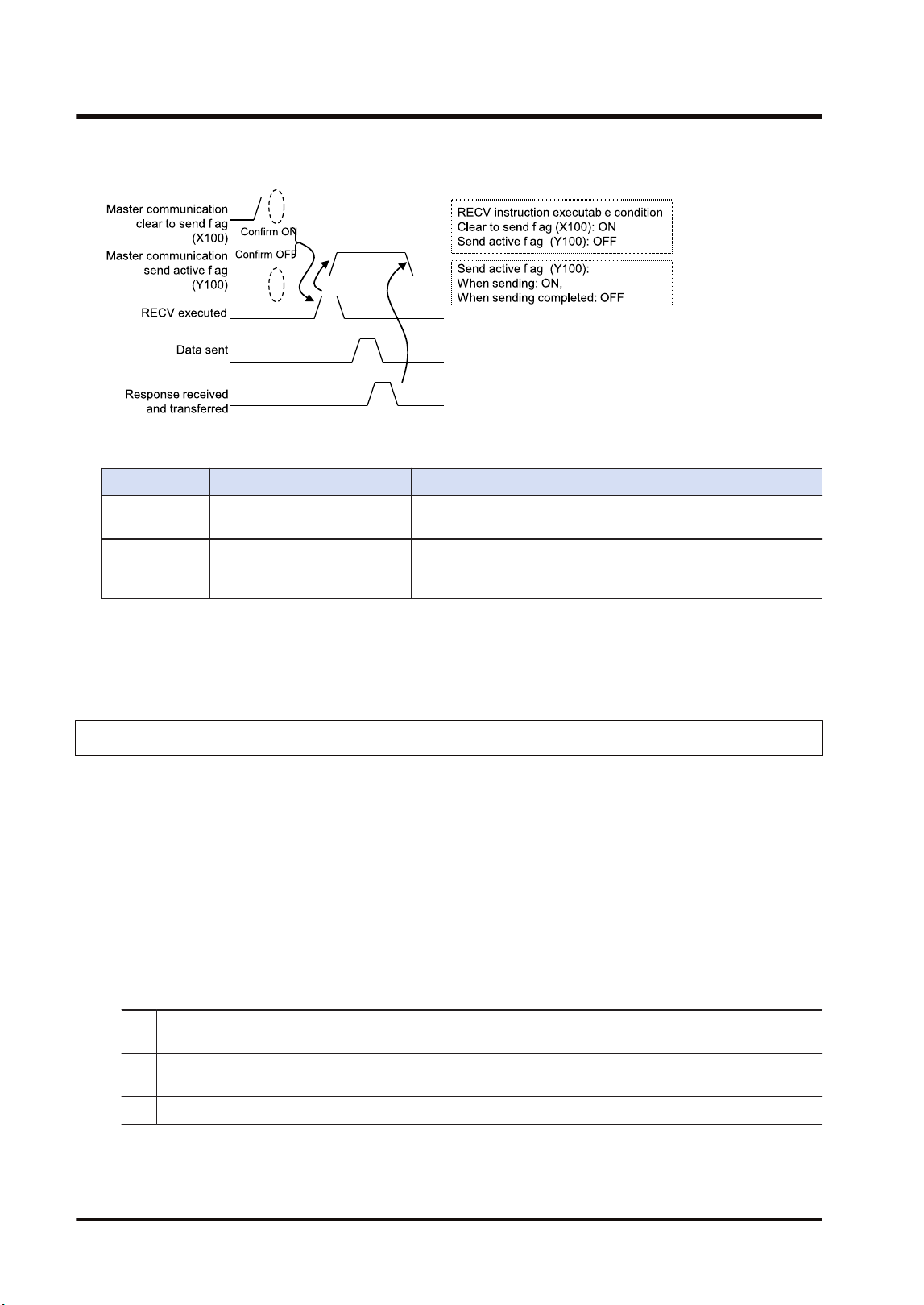
■
Time chart
■
I/O Allocation
I/O number Name Description
X100
Master communication clear
to send flag
Turns ON when the unit number of MEWNET-W has been set
and the unit is in RUN mode.
Y100
Master communication send
active flag
Turns ON during sending data by SEND/RECV instruction.
Turns OFF when the ED instruction is executed after the
completion of the response receive processing.
(Note 1) Each contact in the table above is used for reading the operation status. Do not write them using user
programs.
(Note 2) The above I/O numbers are those for the base word number 10.
4.5.3 Precautions When Using Data Transfer Function
■
Specifications of data transfer function:
● Using the data transfer function, communication can be performed between any units in
either PLC link mode or non-PLC link mode.
● For the FP7 MW Unit, one instruction can be executed for each one unit simultaneously.
● The maximum number of transmission data that can be specified is 55 words (SEND
instruction) and 56 words (RECV instruction) in W mode.
■
Execution condition of SEND/RECV instructions:
● Start the SEND/RECV instruction (message communication) in the W mode of FP7 MW Unit
after any of the following steps.
(1) Confirm that the PLC link transmission assurance relays of the destination unit to send a message or
all units are ON.
(2) Confirm that the information bit of the units being added to the link of the destination unit is ON. The
information on the units added to the link can be monitored by PMGET instruction.
(3) After a certain period of time after power-on (After a few seconds)
● Use the UNITSEL instruction following the SEND/RECV instruction to specify a target slot
number for communication. Specify U0 for [S2] port number.
4.5 Data Transfer
4-18 WUME-FP7MW-06

● Confirm that the "master communication clear to send flag" is ON, and execute the SEND/
RECV instruction.
● Confirm that the "master communication send active flag" is OFF, and execute the SEND/
RECV instruction. For the FP7 MW Unit, one instruction can be executed for each one unit
simultaneously.
● SEND and RECV instructions cannot be executed for the FP7 MW Units during the slave
communication.
● The information on PLC link transmission assurance relays and units added to the link can also
be read by a user program (PMGET instruction).Refer to "9.1.4 PMGET Instruction (For
MEWNET-W2)".
4.5 Data Transfer
WUME-FP7MW-06 4-19

(MEMO)
4-20 WUME-FP7MW-06

5 MEWNET-W2
5.1 Overview.............................................................................................5-2
5.2 Setting the Switches of the Unit..........................................................5-3
5.3 Configuration.......................................................................................5-4
5.3.1 Registration in I/O Map .................................................................... 5-4
5.3.2 No. of Occupied I/O Points of MEWNET-W2 ................................... 5-4
5.3.3 Confirmation of Slot Numbers.......................................................... 5-5
5.3.4 W2 Link Unit Setting Procedure....................................................... 5-6
5.3.5 W2 Link Unit Setting dialog box ....................................................... 5-7
5.3.6 Configuration Using User Programs ................................................ 5-8
5.4 PLC Link .............................................................................................5-10
5.4.1 Example of Link Area Allocation ...................................................... 5-10
5.4.2 PLC Link Operation State Flag ........................................................ 5-11
5.4.3 Link Error Information ...................................................................... 5-12
5.5 Data Transfer ......................................................................................5-13
5.5.1 Data Transfer from Own Unit to Destination Unit (SEND) ............... 5-13
5.5.2 Data Transfer from Destination Unit to Own Unit............................. 5-14
5.5.3 Precautions When Using Data Transfer Function............................ 5-15
WUME-FP7MW-06
5-1

5.1 Overview
The following are main steps to use the FP7 MW Unit in W2 mode.
Item Used tool Outline of operation
(1)
Set the switches of the
unit.
-
Select "W2 mode" by the mode selector switches. Set whether
to use the PLC link or not, and buad rate.
Specify unit number. When setting it in the configuration of tool
software or user program, set it to "00".
(2)
Registration in I/O map
of the unit
FPWIN GR7
Register the unit configuration of the FP7 system in the "I/O
map" dialog box.
Confirm slot numbers specified for each instruction.
When using the data transfer function, confirm the number of
the flag to be checked when executing SEND/RECV
instructions.
(3) Unit Configuration FPWIN GR7
Specify unit number. (When selecting "00" by the unit number
selector of the unit.)
(Note 1)
Allocate link relays and link registers used for the PLC link.
Set the device to which the PLC link operation state flag is
copied.
Set the device to which the link error information output
destination is copied.
(4)
Download the settings
to the unit and confirm
the operation state.
FPWIN GR7
Download "I/O map" and "unit configuration" information to the
FP7 CPU Unit.
Switch the mode to RUN mode.
Confirm the state if the process is normally performed. The
communication state and error information can be confirmed by
the communication state information copy destination device,
system relays or system data registers. Also, detailed
information can be read by PMGET instruction.
(Note 1) The unit number can be set by a user program.
5.1 Overview
5-2 WUME-FP7MW-06

5.2 Setting the Switches of the Unit
For using the FP7 MW Unit as W2 link unit, the switches on the front of the unit need to be set.
■
Mode setting switch
Each mode is set with the four dip switches on the front of the unit.
No. Item Range
1 Operation mode OFF: PLC link mode, ON: Non-PLC link mode
2
Mode Set 2 to ON and 3 to OFF. The unit operates as the unit for "MEWNET-W2".
3
4 Baud rate For "MEWNET-W2", set it to OFF: 500 kbps and ON: 250 kbps.
(Note 1) All the switches are set to OFF at the factory.
(Note 2) Be sure the power is off when changing the switches.
■
Unit number selector
Specify the own unit number by the two rotary switches on the front of the unit.
Range Description
01 to 32 For target unit of PLC link
01 to 64
For target unit of data transfer
(Note 1)
00
When setting it in the configuration of the tool software or user program (PMSET/pPMSET
instruction).
(Note 1) It indicates the range that can be specified. The range of units that can be actually connected is up to
32 units.
(Note 2) Be sure the power is off when changing the switches.
5.2 Setting the Switches of the Unit
WUME-FP7MW-06 5-3
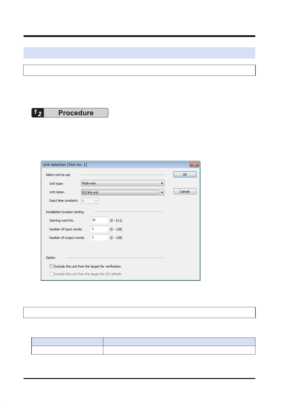
5.3 Configuration
5.3.1 Registration in I/O Map
The unit is allocated to the I/O map in the tool software FPWIN GR7.
■
Allocation method
1. Select Options>FP7 Configuration>I/O map in the menu bar.
2. Double-click the target slot where the operating unit is to be inserted.
The "Unit Selection" dialog box is displayed.
3. Select "Multi-wire" and "W2 link unit" in the "Select unit to use" field.
4. Press the [[OK]] button.
5.3.2 No. of Occupied I/O Points of MEWNET-W2
In W2 mode, the FP7 MW Unit occupies only one word. It is allocated as a flag for executing
the data transfer function (SEND/RECV instruction).
Mode No. of points
W2 mode 1 word / Output: 1 word (Fixed)
5.3 Configuration
5-4 WUME-FP7MW-06
■
I/O Allocation
I/O number Name Description
X100
Master communication clear
to send flag
Turns ON when the unit number of MEWNET-W2 has been set
and the unit is in RUN mode.
Y100
Master communication send
active flag
Turns ON during sending data by SEND/RECV instruction.
Turns OFF when the ED instruction is executed after the
completion of the response receive processing.
(Note 1) Each contact in the table above is used for reading the operation status. Do not write them using user
programs.
(Note 2) The above I/O numbers are those for the base word number 10.
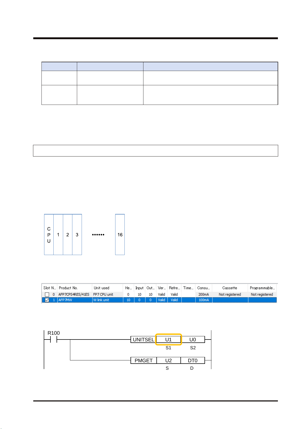
5.3.3 Confirmation of Slot Numbers
Slot numbers are decided by registering units in the I/O map. Slot numbers are used when
reading or writing the values of unit memories by user programs. They are also used when
performing the data monitoring on FPWIN GR7.
■
Slot No.
Slot numbers are decided by each installation position of units. They are counted from the unit
closest to the CPU unit.
■
Display on the I/O map of FPWIN GR7
Slot numbers can be confirmed in the "I/O map" dialog box of FPWIN GR7.
■
Using by user programs
The user program below is that for specifying the slot number.
PMGET DT0U2
R100
UNITSEL U0U1
S1 S2
S D
5.3 Configuration
WUME-FP7MW-06 5-5
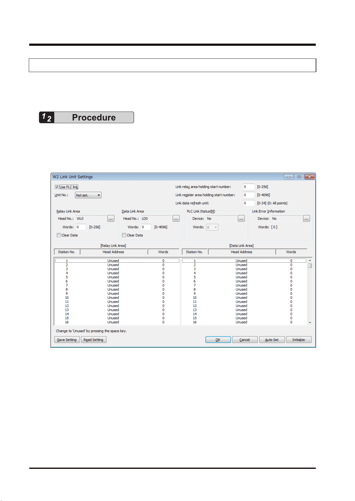
5.3.4 W2 Link Unit Setting Procedure
Link relays and link registers are set in the "W2 Link Unit Settings" dialog box of FPWIN GR7.
The following procedure describes the case that "W2 link unit" has been already registered in
the "I/O map" dialog box.
1. Select Options>FP7 Configuration>I/O map in the menu bar.
The "I/O map" dialog box is displayed.
2. Select the slot where the W2 link unit has been selected, and press the [Advanced] button.
The "W2 Link Unit Settings" dialog box is displayed.
3. Check "Use PLC link" and set the unit number.
When the PLC link is not used, uncheck the checkbox.
4. For the PLC link, set each item relating to link relays and link registers.
5. Press the [[OK]] button.
The window returns to the "I/O map" dialog box.
6. Press the [[OK]] button.
It returns to the edit window of FPWIN GR7. These settings will be downloaded to the CPU
unit together with programs and other configuration information, and will be effective in
RUN mode.
5.3 Configuration
5-6 WUME-FP7MW-06
● Press the [Save Setting] button in the "W2 Link Unit" Settings dialog box to save configuration
data (extension: .fp7mww2) for the W link unit. The configuration data can also be used for
other projects.
● For the details of the setting items of "W2 Link Unit" Settings dialog box, refer to the next page.
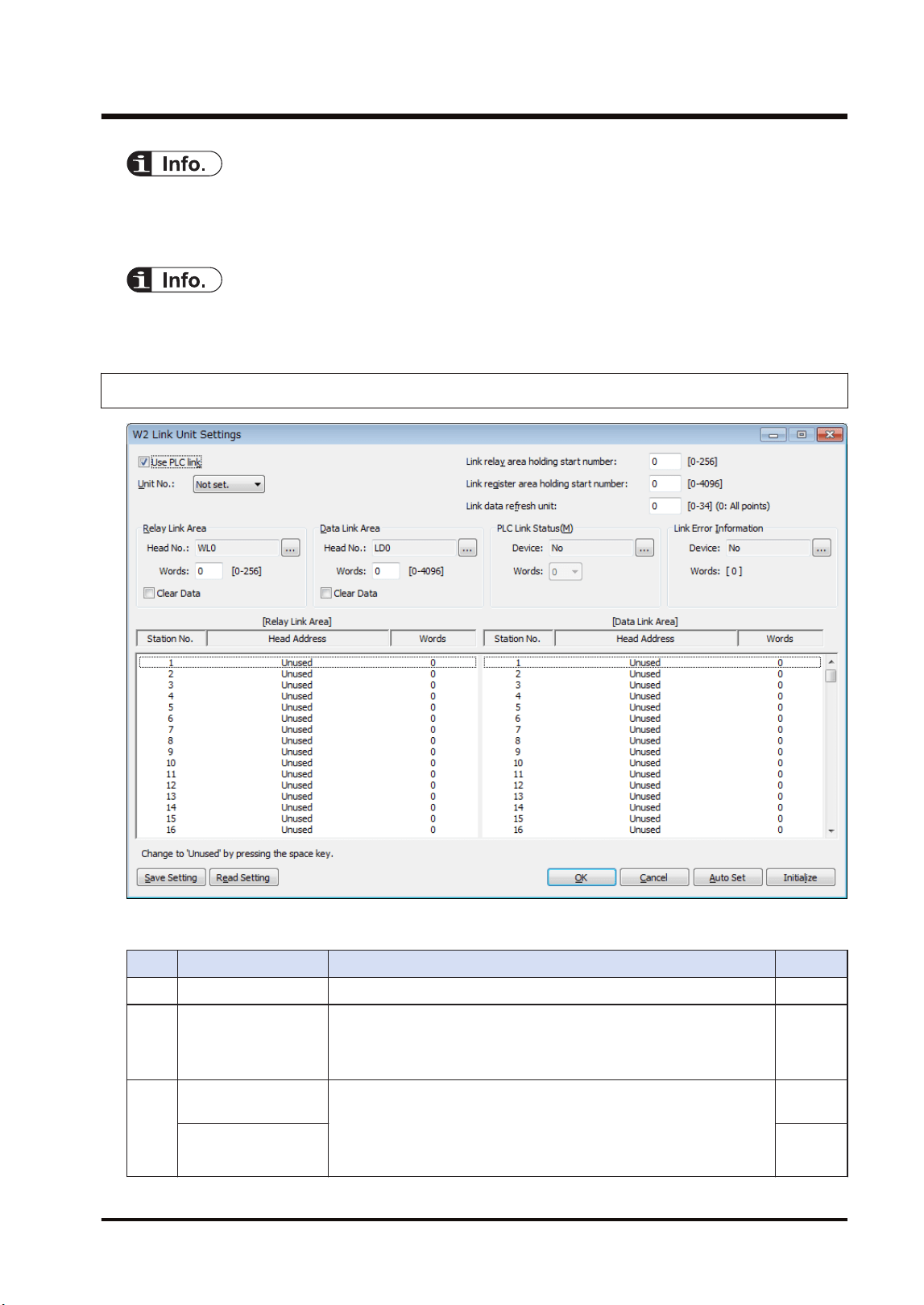
5.3.5 W2 Link Unit Setting dialog box
■
Setting item
No. Item Range Remarks
(1) Use PLC link For using the PLC link, check the checkbox.
(2) Unit No.:
Specify a unit number for the own unit. When setting it using a user
program (PMSET/pPMSET instruction), specify "Not set". The unit
number selector on the front panel of the unit needs to be set to
"00".
(3)
Link relay area
holding start number
Set the starting word number of a device used as hold type. The
holding start number is specified as a relative value from the
beginning of "Relay Link Area" and "Data Link Area".
For link relays: 0-256
For link registers: 0 to 4096
Link register area
holding start number
5.3 Configuration
WUME-FP7MW-06 5-7

No. Item Range Remarks
Example 1) When specifying 0, the area in the selected range is
hold type.
Example 2) When specifying the maximum value, the area in the
selected range is non-hold type.
(4) Link data refresh unit
Specify the unit to refresh the I/O by the PLC link in the format of
(set value x 256 bytes/scan). By default, all points are refreshed
collectively when specifying 0. Although the responsiveness is
improved, the scan time of a single unit becomes longer. When a set
value is changed, data of the set number of bytes is refreshed for
each scan. Although the responsiveness is deteriorated, the scan
time of a single unit becomes shorter.
(5)
Relay Link Area (Own
unit)
Select a device type and number used as link relay.
WL, WR, LD, DT, global device or local device can be used.
Specify a device number.
Specify the usage area of relay link (no. of words). [0-256]
For clearing the area when the PLC link stops, check this checkbox.
(6)
Data Link Area (Own
unit)
Select a device type.
WL, WR, LD, DT, global device or local device can be used.
Specify a device number.
Specify the usage area of data link (no. of words). [0-4096]
For clearing the area when the PLC link stops, check this checkbox.
(7)
PLC Link Operation
State Flag
Specify a device storing the PLC link operation state.
Device type: WL, WR, LD, DT (Global device/Local device)
Device no.: From 0
No. of words: 0, 3, 6
(8)
Link Error Information
Output Destination
Specify a destination device to output link error information.
Device type: WL, WR, LD, DT (Global device/Local device)
Device no.: From 0
(9)
Relay Link Area
(Each unit number)
Specify the transmission starting device number and the number of
sent words for each unit.
No. of sent words: [0-256]
(10)
Data Link Area (Each
unit number)
Specify the transmission starting device number and the number of
sent words for each unit.
No. of sent words: [0-4096]
● For information on configuration examples of link relays and link registers, refer to
"5.4.1 Example of Link Area Allocation".
5.3.6 Configuration Using User Programs
In MEWNET-W2, unit numbers can be set by the user programs (PMSET/pPMSET instruction).
The unit number selector on the front panel of the unit needs to be set to "00".
5.3 Configuration
5-8 WUME-FP7MW-06
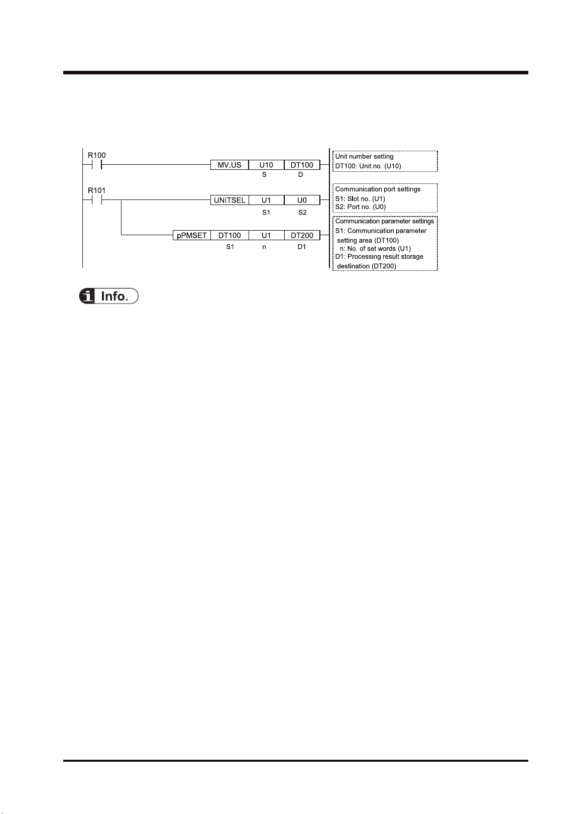
■
Sample program
This sample program shows the case that the unit number for the FP7 MW Unit (W2 link unit) in
the slot number 1 is set to 10.
● For the MEWNET-W2, the link area cannot be allocated by the user programs. Allocate the
area in the "W2 Link Settings" dialog box of the tool software.
5.3 Configuration
WUME-FP7MW-06 5-9
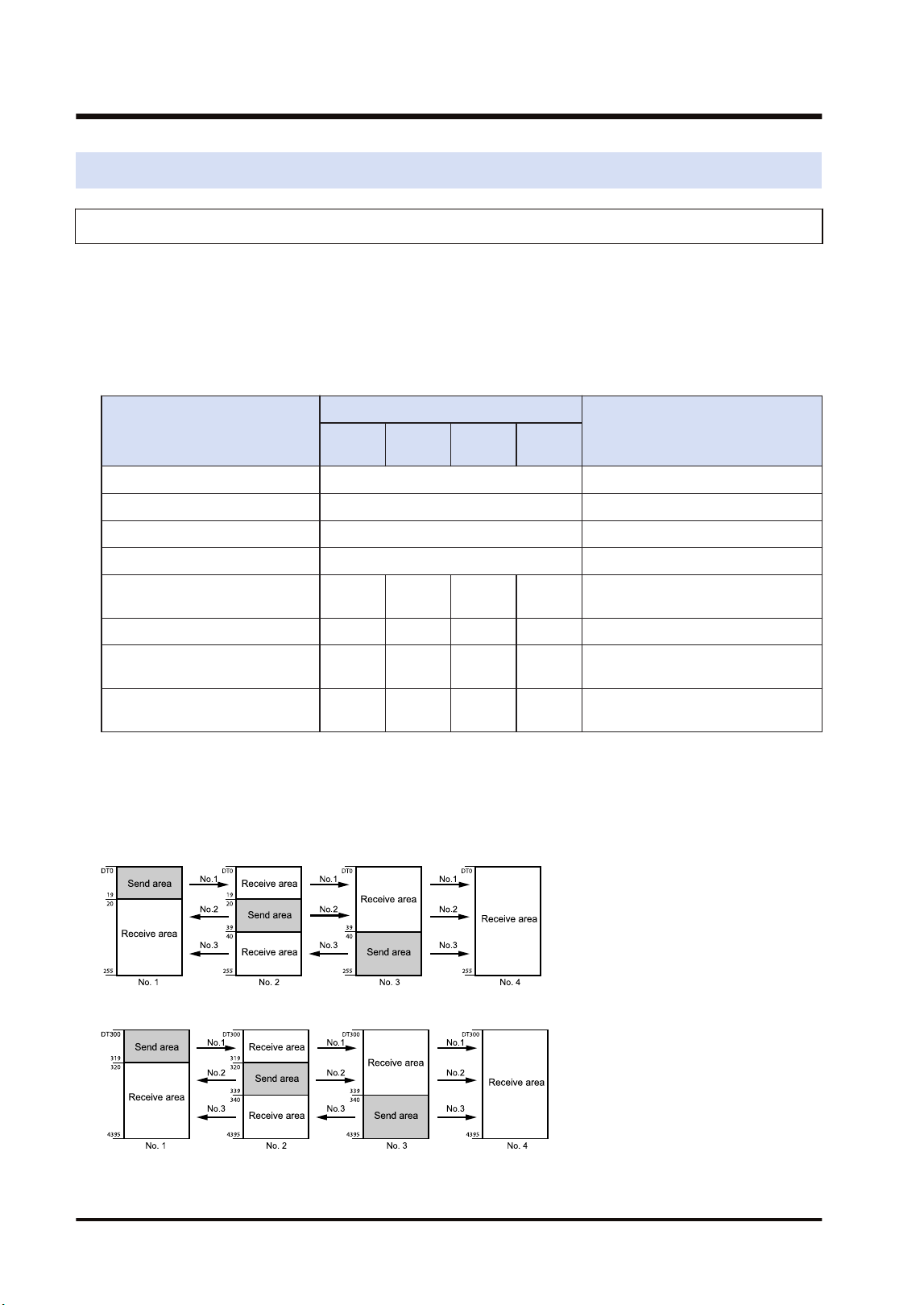
5.4 PLC Link
5.4.1 Example of Link Area Allocation
For MEWNET-W2, a device allocated for the PLC link can be selected from WL, WR, LD and
DT.
■
Link area allocation:
The PLC link area is divided into the send area and receive area for each unit and used. The
link relays and link registers are sent from the send area to the receive area of a different PLC.
Item
Each unit setting
Remarks
Unit no.
1
Unit no.
2
Unit no.
3
Unit no.
4
Range of link relays used DT0
No. of all words for link relays 256
Range of link registers used DT300
No. of all words for link registers 4096
Starting number for link relay
transmission
0 20 40 0
(Note 1)
No. of sent words for link relays 20 20 20 0
Starting number for link register
transmission
0 40 80 0
(Note 2)
No. of sent words for link
registers
40 40 40 0
(Note 1) The link relay transmission start number is specified as a relative value from the beginning of "Range
of link relays used".
(Note 2) The link register transmission start number is specified as a relative value from the beginning of
"Range of link registers used".
- Link relay allocation
- Link register allocation
5.4 PLC Link
5-10 WUME-FP7MW-06
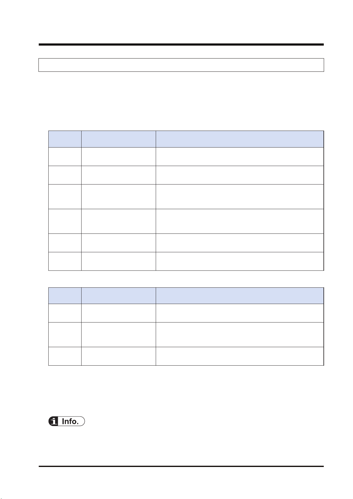
5.4.2 PLC Link Operation State Flag
Information showing the PLC link communication state of the unit can be monitored by the
following flags. The information storage destination is specified in the "W2 Link Unit Settings"
dialog box.
■
Format of PLC link operation state
Format when setting the number of words to 6 in the W2 configuration.
Storage
location
Name Description
[D]
PLC link state monitor flag
Unit nos. 1 to 16
bit0 to bit15: Unit no. 1 to unit no. 16
OFF: Stop, ON: PLC link communicating normally
[D+1]
PLC link state monitor flag
Unit nos. 17 to 32
bit0 to bit15: Unit no. 17 to unit no. 32
OFF: Stop, ON: PLC link communicating normally
[D+2]
PLC link operation mode
flag
Unit nos. 1 to 16
bit0 to bit15: Unit no. 1 to unit no. 16
OFF: PROG. mode, ON: RUN mode
[D+3]
PLC link operation mode
flag
Unit nos. 17 to 32
bit0 to bit15: Unit no. 17 to unit no. 32
OFF: PROG. mode, ON: RUN mode
[D+4]
PLC link operation state flag
Unit nos. 1 to 16
bit0 to bit15: Unit no. 1 to unit no. 16
OFF: Error occurs in PLC transmission is ensured, ON: No error.
[D+5]
PLC link operation state flag
Unit nos. 17 to 32
bit0 to bit15: Unit no. 17 to unit no. 32
OFF: Error occurs in PLC transmission is ensured, ON: No error.
Format when setting the number of words to 3 in the W2 configuration.
Storage
location
Name Description
[D]
PLC link state monitor flag
Unit nos. 1 to 16
bit0 to bit15: Unit no. 1 to unit no. 16
OFF: Stop, ON: PLC link communicating normally
[D+1]
PLC link operation mode
flag
Unit nos. 1 to 16
bit0 to bit15: Unit no. 1 to unit no. 16
OFF: PROG. mode, ON: RUN mode
[D+2]
PLC link operation state flag
Unit nos. 1 to 16
bit0 to bit15: Unit no. 1 to unit no. 16
OFF: Error occurs in PLC transmission is ensured, ON: No error.
(Note 1) The storage destination is determined by the device specified for "Communication state information
copy destination device" in the "W2 Link Unit Settings" dialog box. When selecting WR10, they are
allocated as follows.
PLC link transmission assurance relay: WR100 to WR10F, PLC link operation mode relay: WR110 to
WR11F, PLC link operation state flag: WR120 to WR12F
● The PLC link operation state flag can also be read by a user program PMGET
instruction).Refer to "9.1.4 PMGET Instruction (For MEWNET-W2)".
5.4 PLC Link
WUME-FP7MW-06 5-11
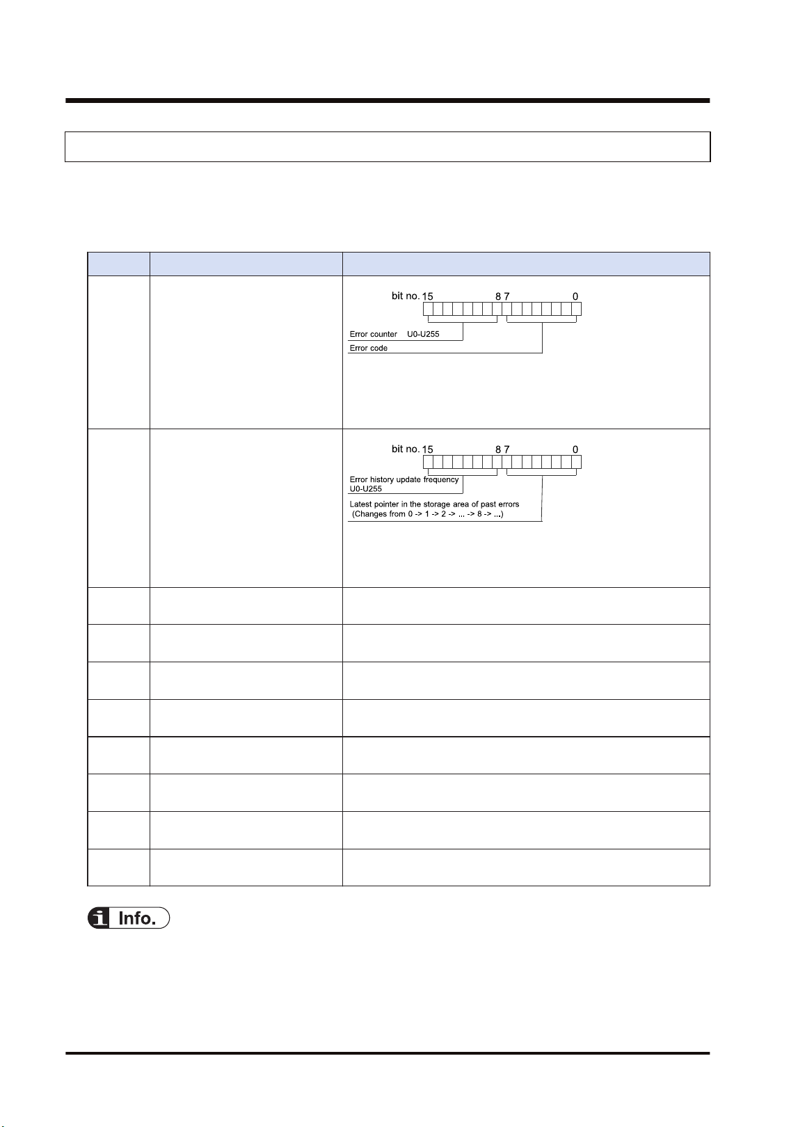
5.4.3 Link Error Information
The link error information of the units can be monitored by the following flags. The information
storage destination is specified in the "W2 Link Unit Settings" dialog box.
■
Format of link error information
Item Description
[D] State of error currently occurs
When the same error occurs, the error counter of high byte will
be updated. When the error content changes and the error is
cleared, the information will be stored in the error occurrence
state history area ([D+2] to [D+9]).
[D+1]
Error occurrence state history
management
When the latest pointer in the storage area of past errors is 0, it
indicates that there is no error. When the number of error
updates is 0, it indicates that there is no update.
[D+2] Error occurrence state history
area 1
History of error occurrence state (parameter of [D]) 1
[D+3] Error occurrence state history
area 2
History of error occurrence state (parameter of [D]) 2
[D+4] Error occurrence state history
area 3
History of error occurrence state (parameter of [D]) 3
[D+5] Error occurrence state history
area 4
History of error occurrence state (parameter of [D]) 4
[D+6] Error occurrence state history
area 5
History of error occurrence state (parameter of [D]) 5
[D+7] Error occurrence state history
area 6
History of error occurrence state (parameter of [D]) 6
[D+8] Error occurrence state history
area 7
History of error occurrence state (parameter of [D]) 7
[D+9] Error occurrence state history
area 8
History of error occurrence state (parameter of [D]) 8
● The PLC link operation state flag can also be read by a user program PMGET
instruction).Refer to "9.1.4 PMGET Instruction (For MEWNET-W2)".
5.4 PLC Link
5-12 WUME-FP7MW-06
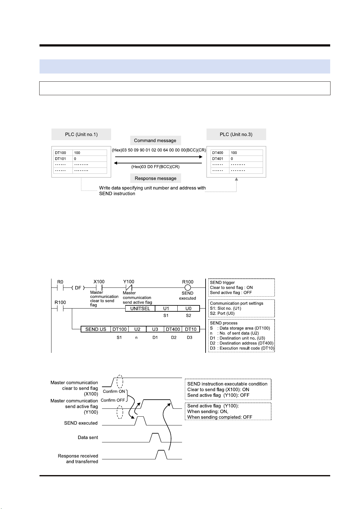
5.5 Data Transfer
5.5.1 Data Transfer from Own Unit to Destination Unit (SEND)
In MEWNET-W2, data can be transferred by specifying an arbitrary unit number or device in a
user program. The PLC generates a message according to the protocol automatically.
Destination PLCs need no program for sending/receiving data.
■
Sample Program (Word transmission)
● Transfers the content of the device for operation (DT100 to DT101) of the own unit to the
device for operation (DT400 to DT401) of a destination unit via the MW Unit installed in the
slot 1.
● The SEND instruction is executed by specifying the starting address (DT100) and number of
DATA (U2) of the source unit and the unit number (U3) and starting address (DT400) of the
destination unit.
● The execution result code is set in DT10 of the own unit.
■
Time chart
5.5 Data Transfer
WUME-FP7MW-06 5-13
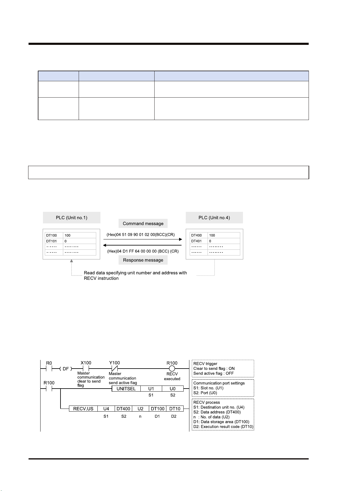
■
I/O Allocation
I/O number Name Description
X100
Master communication clear
to send flag
Turns ON when the unit number of MEWNET-W2 has been set
and the unit is in RUN mode.
Y100
Master communication send
active flag
Turns ON during sending data by SEND/RECV instruction.
Turns OFF when the ED instruction is executed after the
completion of the response receive processing.
(Note 1) Each contact in the table above is used for reading the operation status. Do not write them using user
programs.
(Note 2) The above I/O numbers are those for the base word number "10".
5.5.2 Data Transfer from Destination Unit to Own Unit
In MEWNET-W2, data can be transferred by specifying an arbitrary unit number or device in a
user program. The PLC generates a message according to the protocol automatically.
Destination PLCs need no program for sending/receiving data.
■
Sample Program (Word reception)
● Reads and transfers the content of the device for operation (DT400 to DT401) of a
destination unit to the device for operation (DT100 to DT101) of the own unit via the MW Unit
installed in the slot 1.
● The RECV instruction is executed by specifying the unit number (U4), starting address
(DT400) and number of data (U2) of the destination unit and the starting address (DT100) of
the own unit.
● The execution result code is set in DT10 of the own unit.
5.5 Data Transfer
5-14 WUME-FP7MW-06
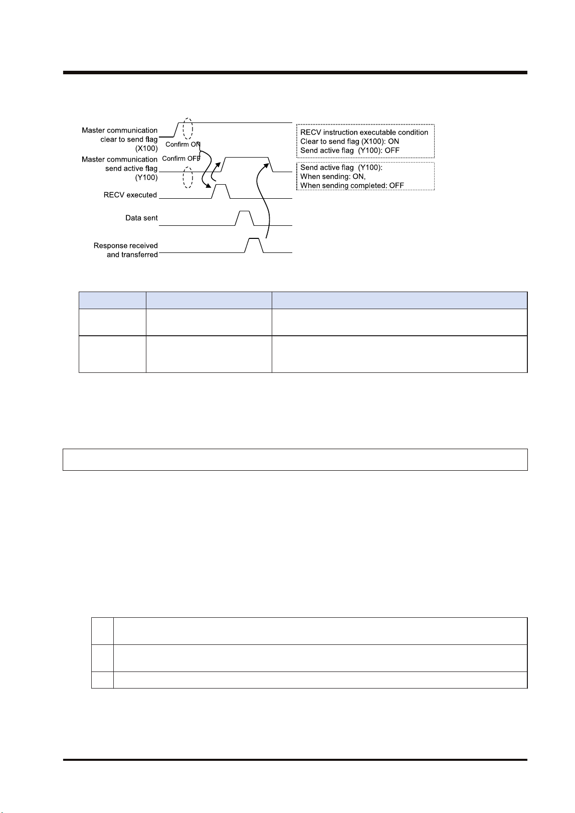
■
Time chart
■
I/O Allocation
I/O number Name Description
X100
Master communication clear
to send flag
Turns ON when the unit number of MEWNET-W2 has been set
and the unit is in RUN mode.
Y100
Master communication send
active flag
Turns ON during sending data by SEND/RECV instruction.
Turns OFF when the ED instruction is executed after the
completion of the response receive processing.
(Note 1) Each contact in the table above is used for reading the operation status. Do not write them using user
programs.
(Note 2) The above I/O numbers are those for the base word number "10".
5.5.3 Precautions When Using Data Transfer Function
■
Specifications of data transfer function:
● Using the data transfer function, communication can be performed between any units in
either PLC link mode or non-PLC link mode.
● For the FP7 MW Unit, one instruction can be executed for each one unit simultaneously.
● The maximum number of transmission data that can be specified is 1020 words.
■
Execution condition of SEND/RECV instructions:
● Start the SEND/RECV instruction (message communication) in the W2 mode of FP7 MW
Unit after any of the following steps.
(1)
Confirm that the PLC link transmission assurance relays of the destination unit to send a message or
all units are ON.
(2)
Confirm that the information bit of the units being added to the link of the destination unit is ON. The
information on the units added to the link can be monitored by PMGET instruction.
(3) After a certain period of time after power-on (After a few seconds)
● Use the UNITSEL instruction following the SEND/RECV instruction to specify a target slot
number for communication. Specify (U0) for [S2] port number.
● Confirm that the "master communication clear to send flag" is ON, and execute the SEND/
RECV instruction.
5.5 Data Transfer
WUME-FP7MW-06 5-15

● Confirm that the "master communication send active flag" is OFF, and execute the SEND/
RECV instruction. For the FP7 MW Unit, one instruction can be executed for each one unit
simultaneously.
● SEND and RECV instructions cannot be executed for the FP7 MW Units during the slave
communication.
● The information on PLC link transmission assurance relays and units added to the link can also
be read by a user program (PMGET instruction).Refer to "9.1.4 PMGET Instruction (For
MEWNET-W2)".
5.5 Data Transfer
5-16 WUME-FP7MW-06

6 MEWNET-F
6.1 Overview.............................................................................................6-2
6.2 Settings of the Unit..............................................................................6-3
6.3 Configuration.......................................................................................6-4
6.3.1 Registration in I/O Map .................................................................... 6-4
6.3.2 Number of Occupied I/O Points for the Unit..................................... 6-4
6.3.3 Confirmation of Slot Numbers.......................................................... 6-5
6.3.4 F Link Unit Setting Procedure .......................................................... 6-5
6.3.5 F Link Unit Setting Dialog Box ......................................................... 6-7
6.4 Allocation of Remote I/O Map.............................................................6-9
6.4.1 I/O Numbers Allocated to Slaves ..................................................... 6-9
6.4.2 Registration by Configuration........................................................... 6-11
6.4.3 Online Mount Allocation ................................................................... 6-13
6.5 Starting MEWNET-F System ..............................................................6-15
6.5.1 Check Before Turning On the Power ............................................... 6-15
6.5.2 Power-on and Power-off Sequences ............................................... 6-15
6.5.3 Setting and Operation of Slave Connection Wait Time.................... 6-15
6.6 Checking Before Operation (Before Switching to RUN Mode) ...........6-17
6.6.1 Checking Communication State....................................................... 6-17
6.7 Behavior During Operation .................................................................6-18
6.7.1 Remote I/O Refresh ......................................................................... 6-18
WUME-FP7MW-06
6-1
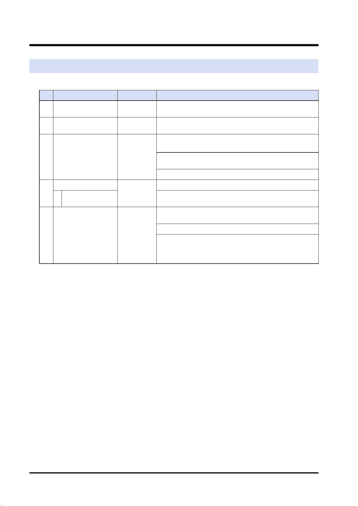
6.1 Overview
The following are main steps to use the FP7 MW Unit in F mode.
Item Used tool Outline of operation
(1)
Set the switches of the
unit.
-
Select "F mode" by the mode selector switches. Sets the
operation mode in an abnormal state.
(2)
Set the switches of
slave units.
-
Set the unit numbers of connected slave units by the dip
switches of each slave unit.
(3)
Registration in I/O map
of the unit
FPWIN GR7
Register the unit configuration of the FP7 system in the "I/O
map" dialog box.
(Note 1)
For the F mode, set the number of I/O words allocated to slave
units and base numbers of I/O numbers.
Confirm slot numbers specified for each instruction.
(4)
Unit Configuration
FPWIN GR7
Set the slave unit connection wait time and I/O refresh method.
Allocation of Remote
I/O Map
Allocate I/O for slave units.
(Note 1)
(5)
Download the settings
to the unit and confirm
the operation state.
FPWIN GR7
Download "I/O map" and "unit configuration" information to the
FP7 CPU Unit.
Switch the mode to RUN mode.
Confirm the state if the process is normally performed. The
communication state and error information can be confirmed by
system relays or system data registers. Also, detailed
information can be read by PMGET instruction.
(Note 1) I/O can be allocated by mount allocation.
6.1 Overview
6-2 WUME-FP7MW-06
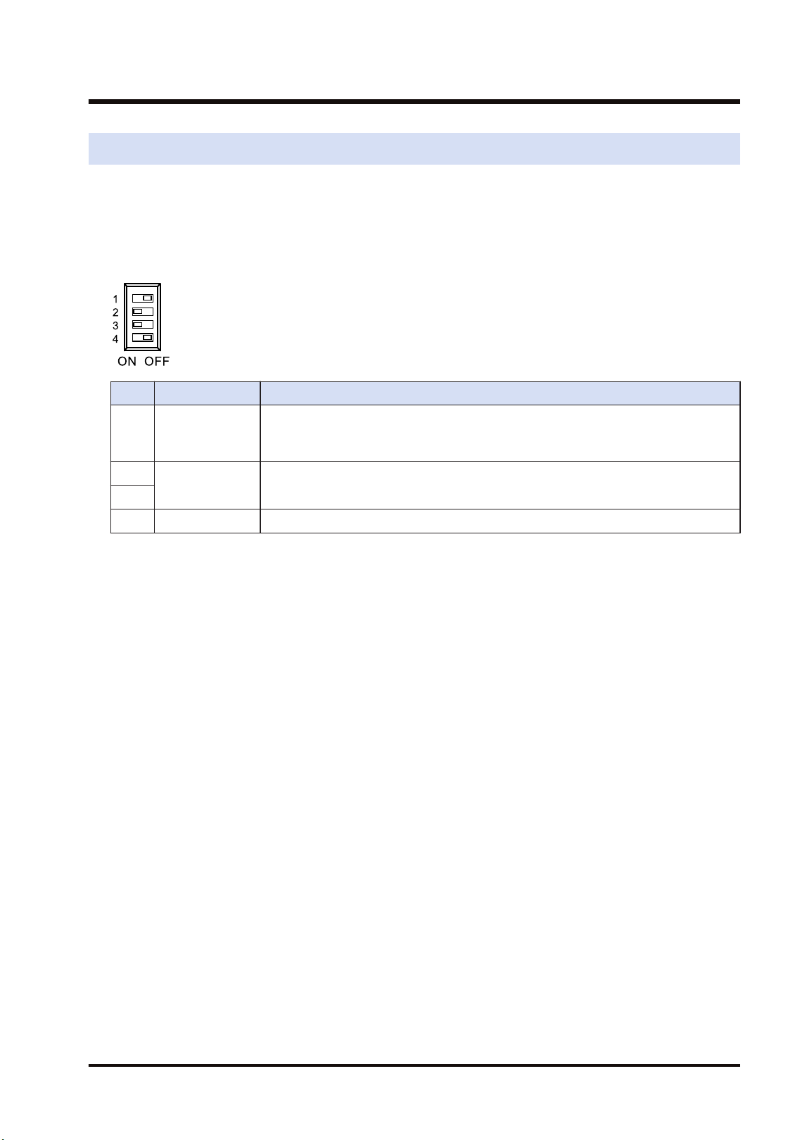
6.2 Settings of the Unit
For using the FP7 MW Unit as F link unit, the switches on the front panel of the unit need to be
set.
■
Mode setting switch
Each mode is set with the four dip switches on the front of the unit.
No. Item Range
1 Operation mode
Select the operation mode of the FP7 MW Unit when an error occurs.
OFF: Stops operation in case of communication error, ON: Continues operation in
case of communication error
2
Mode Set 2 and 3 to ON. The unit operates as the unit for "MEWNET-F".
3
4 Baud rate For "MEWNET-F", it is fixed at 500 kbps.
(Note 1) Be sure the power is off when changing the switches.
(Note 2) All the switches are set to OFF at the factory.
■
Unit number selector
It is not used in F mode.
6.2 Settings of the Unit
WUME-FP7MW-06 6-3
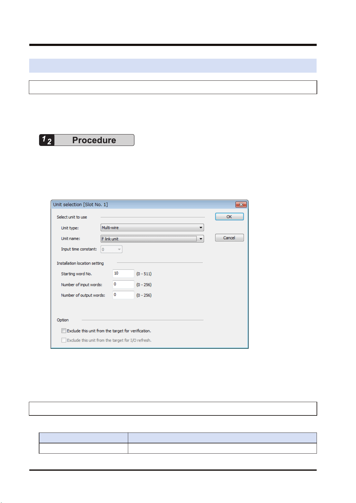
6.3 Configuration
6.3.1 Registration in I/O Map
The unit is allocated to the I/O map in the tool software FPWIN GR7.
■
Allocation method
1. Select Options>FP7 Configuration>I/O map in the menu bar.
2. Double-click the target slot where the operating unit is to be inserted.
The "Unit Selection" dialog box is displayed.
3. Select "Multi-wire" and "F link unit" in the "Select unit to use" field.
4. Input the number of input words and the number of output words according to the
connected configuration.
5. Press the [[OK]] button.
6.3.2 Number of Occupied I/O Points for the Unit
For the F mode, the number of I/O points allocated to the remote I/O part is occupied.
Mode No. of points
F mode Input: 0 to 256 words / Output: 0 to 256 words
6.3 Configuration
6-4 WUME-FP7MW-06
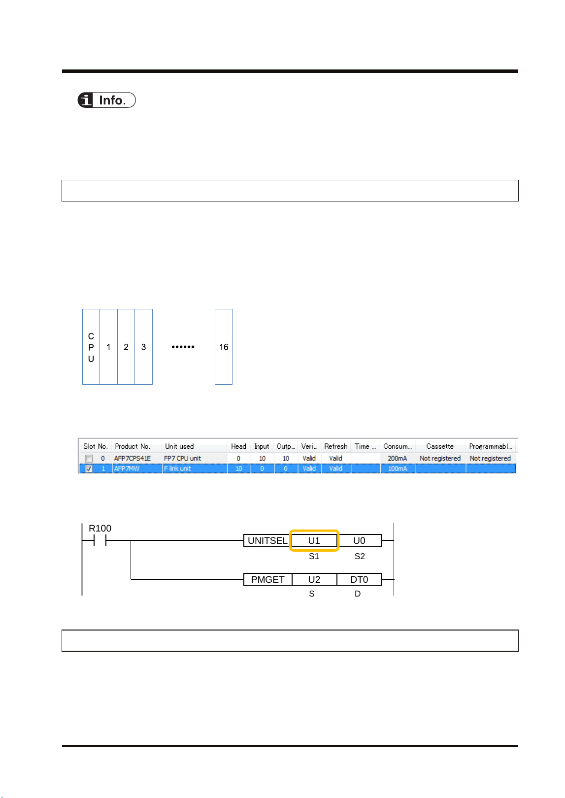
● Set the numbers of input words and output words according to the configuration of connected
remote I/O. When the allocation of occupied I/O points is not enough, it is necessary to change
the allocation of I/O map along with other units.
6.3.3 Confirmation of Slot Numbers
Slot numbers are decided by registering units in the I/O map. Slot numbers are used when
reading or writing the values of unit memories by user programs. They are also used when
performing the data monitoring on FPWIN GR7.
■
Slot No.
Slot numbers are decided by each installation position of units. They are counted from the unit
closest to the CPU unit.
■
Display on the I/O map of FPWIN GR7
Slot numbers can be confirmed in the "I/O map" dialog box of FPWIN GR7.
■
Using by user programs
The user program below is that for specifying the slot number.
PMGET DT0U2
R100
UNITSEL U0U1
S1 S2
S D
6.3.4 F Link Unit Setting Procedure
The allocations of the slave unit connection wait time, I/O refresh method and MEWNET-F
slave unit I/O are set in the "F Link Unit Settings" dialog box of FPWIN GR7. The following
procedure describes the case that "F link unit" has been already registered in the "I/O map
dialog" box.
6.3 Configuration
WUME-FP7MW-06 6-5
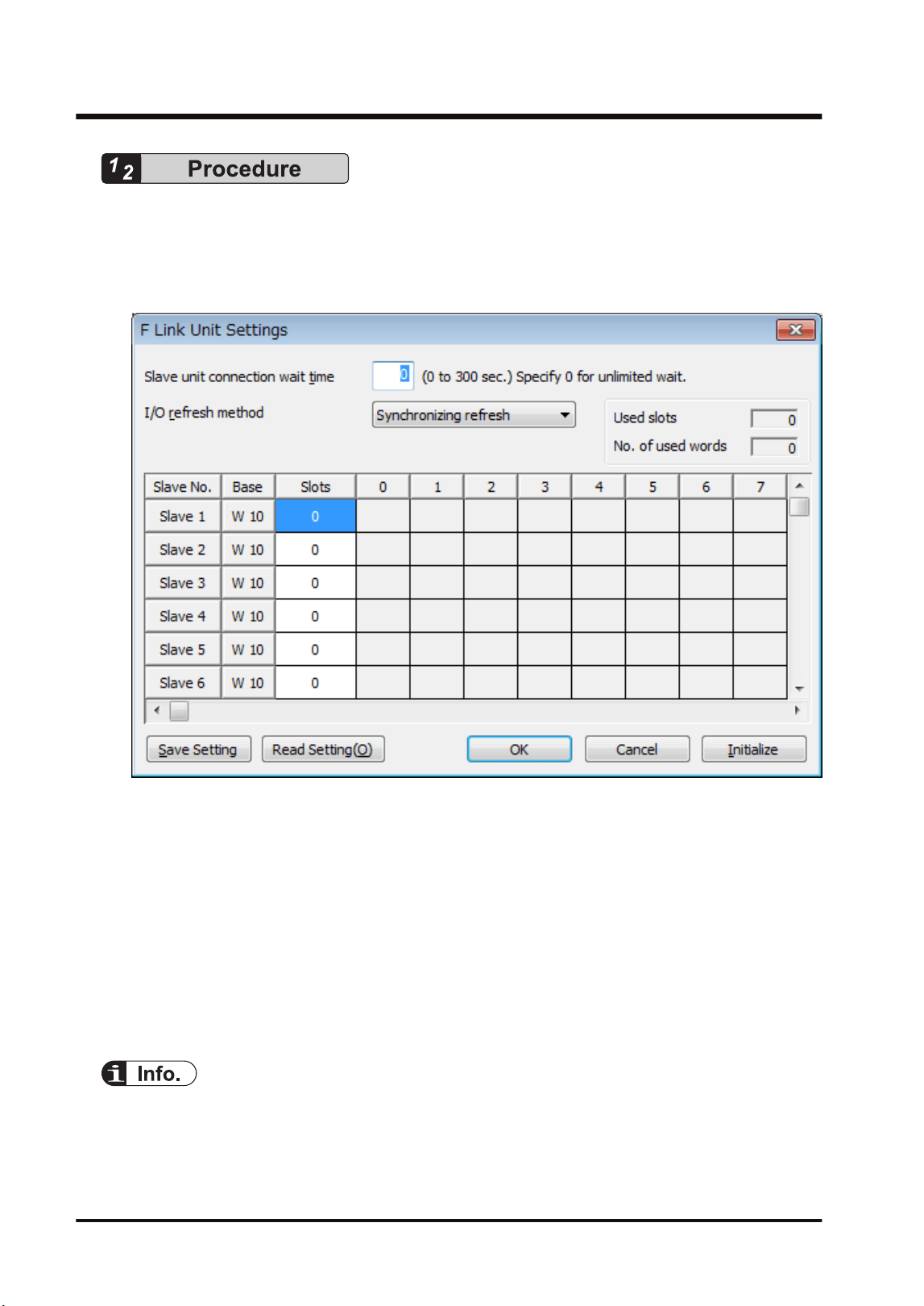
1. Select Options>FP7 Configuration>I/O map in the menu bar.
The "I/O map" dialog box is displayed.
2. Select the slot where the F link unit has been selected, and press the [Advanced] button.
The "F Link Unit Settings" dialog box is displayed.
3. Confirm "Slave unit connection wait time" and change the setting as necessary.
4. Confirm "I/O refresh method" and change the setting as necessary.
5. Set the I/O allocation for slave units.
6. Press the [[OK]] button.
The window returns to the "I/O map" dialog box.
7. Press the [[OK]] button.
It returns to the edit window of FPWIN GR7. These settings will be downloaded to the CPU
unit together with programs and other configuration information, and will be effective in
RUN mode.
● Press the [Save Setting] button in the "F Link Unit Settings" dialog box to save configuration
data (extension: .fp7mwf) for the W link unit. The configuration data can also be used for other
projects.
6.3 Configuration
6-6 WUME-FP7MW-06
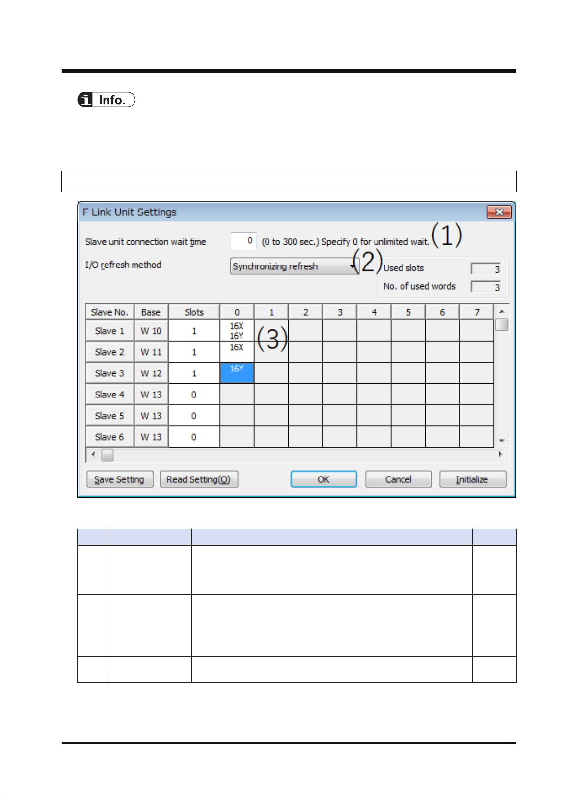
● For the details of the setting items of "F link unit" dialog box, refer to the next page.
● For information on the allocation of slave units, refer to "6.4 Allocation of Remote I/O Map".
6.3.5 F Link Unit Setting Dialog Box
■
Setting item
No. Item Range Remarks
(1)
Slave unit
connection wait
time
Set a time to determine the state that a slave unit is not connected as
an error when the power is turned on. When it is set to 0, a standby
state continues until the slave unit communicates normally.
Range: 0 to 300 seconds
"P.6-15"
(2) I/O refresh method
Select the /O refresh method of remote I/O.
Synchronizing refresh: The normal I/O refresh is executed
synchronously with a scan of remote I/O.
Asynchronizing refresh: The normal I/O refresh is executed
asynchronously with a scan of remote I/O.
"P.6-18"
(3)
Slave unit I/O
allocation field
Set the numbers of input points and output points according to the
types of used slave units.
6.3 Configuration
WUME-FP7MW-06 6-7

● The I/O allocation for slave units can also be made by turning on the power supply when the
slave units are connected and pressing the [Mount] button in the online "I/O map setting" dialog
box.Refer to "6.4.3 Online Mount Allocation".
● For information on the difference between operations according to the slave unit connection
wait time, refer to "6.5.3 Setting and Operation of Slave Connection Wait Time".
● For information on the difference between operations according to the I/O refresh methods,
refer to "6.7.1 Remote I/O Refresh".
6.3 Configuration
6-8 WUME-FP7MW-06

6.4 Allocation of Remote I/O Map
6.4.1 I/O Numbers Allocated to Slaves
I/O numbers allocated to each slave unit of the MEWNET-F system by FP7 are determined by
the starting word numbers and slave numbers of a connected master unit.
■
Slave types and allocated I/O numbers
The following I/O numbers are those when the starting word number is "10" and slave number
is "1".
Item name
Product
number
No. of
inputs/
outputs
I/O no.
Input Output
FP I/O terminal unit
(Primary unit)
AFP87421 Input: 8
points
X100 to X107 -
AFP87422 Input: 16
points
X100 to X10F -
AFP87423 Output: 8
points
- Y100 to Y107
AFP87424 Output: 16
points
- Y100 to Y10F
FP I/O terminal unit
(Expansion unit)
AFP87425 Input: 8
points
X110 to X117 -
AFP87426 Input: 16
points
X110 to X11F -
AFP87427 Output: 8
points
- Y110 to Y117
AFP87428 Output: 16
points
- Y110 to Y11F
FP I/O terminal board
[Terminal block type]
AFP87432 Input: 16
points
Output: 8
points
X100 to X10F Y100 to Y107
AFP87444 Input: 16
points
Output: 16
points
X100 to X10F Y100 to Y10F
FP I/O terminal board [MIL
connector type]
AFP87445
AFP87446
Input: 16
points
Output: 16
points
X100 to X10F Y100 to Y10F
(Note 1) 16 points are used by the 8-point unit.
(Note 2) The allocated settings vary according to the combination of primary unit and expansion units.
Combination No. of occupied I/O points in software
Primary unit (Input) + Expansion unit (Input) 32-point input (32X)
Primary unit (Input) + Expansion unit (Output) 16-point input (16X) / 16-point output (16Y)
6.4 Allocation of Remote I/O Map
WUME-FP7MW-06 6-9
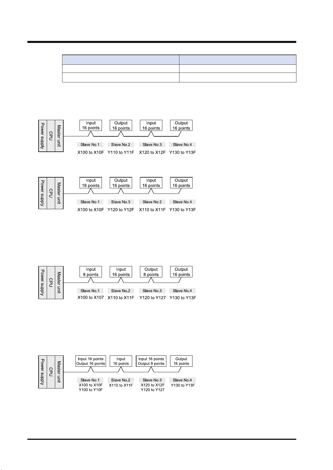
Combination No. of occupied I/O points in software
Primary unit (Output) + Expansion unit (Input)
Primary unit (Output) + Expansion unit (Output) 32-point output (32Y)
■
Order of allocated I/O numbers
I/O numbers for slave units are allocated in the order of slave numbers set with the switch of
each slave unit.
I/O numbers for slave units are allocated in the order of slave numbers regardless of the
connecting order of slave units.
■
I/O numbers allocated when 8-type units are mixed
As 16-point I/Os are allocated even for an 8-point type, dead numbers occur between the unit
and a subsequent unit with the next slave number.
Example) When the I/O numbers for the 8-type slave no. 1 are X100 to X107, X108 to X10F are
dead numbers. The I/O numbers for the slave no. 2 start from X110 or Y110.
■
How to count I/O numbers for units that have both inputs and outputs
In the case of a unit that has both inputs and outputs, input numbers and output numbers start
with the same value.
Example) If input numbers for an I/O terminal board (input 16 points / output 16 points) are
X100 to X10F, the unit's output numbers are set at Y100 to Y10F.
6.4 Allocation of Remote I/O Map
6-10 WUME-FP7MW-06
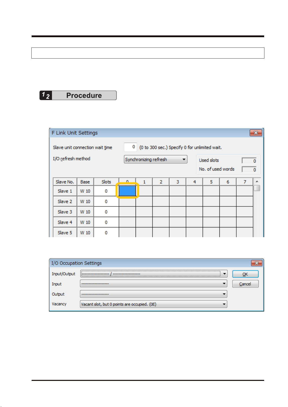
6.4.2 Registration by Configuration
This section describes the procedure for setting the I/O allocation of MEWNET-F slave units in
the "F Link Unit Settings" dialog box of FPWIN GR7. The following are operations in the "F Link
Unit Settings" dialog box.
1. Double-click the slot in which "F link unit" has been registered in the "I/O Map Settings"
dialog box.
The "F Link Unit Settings" dialog box is displayed.
2. Double-click the position of a slave unit to be registered.
The "I/O Occupation Settings" dialog box is displayed.
3. Select "I/O Occupation Settings" according to the used slave unit, and press the [OK]
button.
The symbols indicating the number of I/O points are registered and the number of slots is
updated. In the base column, the word number is displayed.
4. Repeat the above steps according to your system configuration.
5. Press the [[OK]] button.
The window returns to the "I/O map" dialog box.
6.4 Allocation of Remote I/O Map
WUME-FP7MW-06 6-11
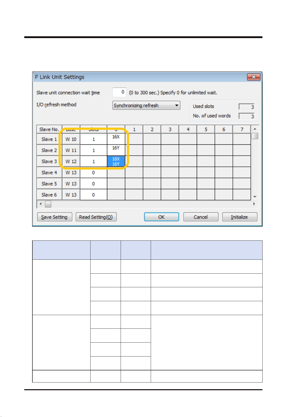
Setting example
The following figure shows the case when three slave units are registered in the remote I/O
map. The base word number and slot number of each slave unit is automatically input.
Unit type and I/O occupation settings
Item name Product
number
No. of
inputs/
outputs
No. of occupied I/O points in software
FP I/O terminal unit
(Primary unit)
AFP87421
Input: 8
points
16-point input (16X)
AFP87422
Input: 16
points
16-point input (16X)
AFP87423
Output: 8
points
16-point output (16Y)
AFP87424
Output: 16
points
16-point output (16Y)
FP I/O terminal unit
(Expansion unit)
AFP87425
Input: 8
points
(Note 2)
AFP87426
Input: 16
points
AFP87427
Output: 8
points
AFP87428
Output: 16
points
FP I/O terminal board
[Terminal block type]
AFP87432
Input: 16
points
16-point input (16X) / 16-point output (16Y)
6.4 Allocation of Remote I/O Map
6-12 WUME-FP7MW-06
Item name Product
number
No. of
inputs/
outputs
No. of occupied I/O points in software
Output: 8
points
AFP87444
Input: 16
points
Output: 16
points
16-point input (16X) / 16-point output (16Y)
FP I/O terminal board [MIL
connector type]
AFP87445
AFP87446
Input: 16
points
Output: 16
points
16-point input (16X) / 16-point output (16Y)
(Note 1) 16 points are used by the 8-point unit.
(Note 2) The allocated settings vary according to the combination of primary unit and expansion units.
Combination No. of occupied I/O points in software
Primary unit (Input) + Expansion unit (Input) 32-point input (32X)
Primary unit (Input) + Expansion unit (Output)
Primary unit (Output) + Expansion unit (Input)
16-point input (16X) / 16-point output (16Y)
Primary unit (Output) + Expansion unit (Output) 32-point output (32Y)
6.4.3 Online Mount Allocation
This section describes the procedure for configuring units by changing to the online mode and
reading the mounting state connected to MEWNET-F.
1. Confirm that the FP7 MW Unit and slave units are connected.
2. Turn on slave units first, and then FP7 MW Unit.
3. Select Online>Switch to Online Mode from the menu bar. Or select "Upload from PLC".
4. Select“Options>FP7 Configuration”>I/O mapin the menu bar
The "I/O map" dialog box is displayed.
5. Confirm that "F link unit" has been registered in the I/O map.
6. Press the [Mount] button.
The mounting state of FP7 including remote I/O slave units is read. Also, it is written as the
configuration information in the FP7 CPU Unit.
6.4 Allocation of Remote I/O Map
WUME-FP7MW-06 6-13

● For performing the mount allocation of "Remote I/O allocation" with the FP7 MW Unit, "F link
unit" must be registered in the I/O map in advance.
● By executing the "mount allocation", the mounting state of the CPU unit, I/O unit and advanced
unit is read besides "Remote I/O allocation" connected to the FP7 MW Unit, and the I/O map is
updated. Check if the design content matches the mounting state in the I/O map.
6.4 Allocation of Remote I/O Map
6-14 WUME-FP7MW-06

6.5 Starting MEWNET-F System
6.5.1 Check Before Turning On the Power
Check the following items before starting the system to prevent malfunction and accidents.
■
Items to check
1. Check to make sure the various devices have been connected as indicated by the design.
2. Check to make sure settings have been entered so that power supplies will be turned on
according to the following order.
3. Check to make sure the CPU unit starts in PROG. mode in the initial state.
6.5.2 Power-on and Power-off Sequences
Start the PHLS system by the following procedure to prevent the malfunction when the system
starts or stops.
■
Procedure for Turning On the Power
1. Turn on I/O devices connected to MEWNET-F slave units.
2. Turn on the MEWNET-F slave units.
3. Turn on the FP7 to which the FP7 MW Unit is installed.
■
Procedure for Turning Off the Power
1. Turn off the FP7 to which the FP7 MW Unit is installed.
2. Turn off the MEWNET-F slave units.
3. Turn off I/O devices connected to MEWNET-F slave units.
6.5.3 Setting and Operation of Slave Connection Wait Time
The operation of switching the mode from PROG. to RUN when the power turns on, after
making the FP7 configuration or downloading a project varies according to the setting of the
slave connection wait time.
■
Operation when the connection wait time is set to "0"
● Waits until the registered slave units start. Until then, the PROG.LED of the CPU unit flashes.
During this processing, the mode cannot be switched to RUN mode.
● If slave units start when turning on the power in RUN mode or switching the mode from
PROG. to RUN, the mode changes to RUN mode.changes to RUN mode.
■
Operation when the connection wait time is set to "1 to 300 seconds"
● During the specified wait time, waits until the registered slave units start. Until then, the
PROG.LED of the CPU unit flashes. During this processing, the mode cannot be switched to
RUN mode.
6.5 Starting MEWNET-F System
WUME-FP7MW-06 6-15
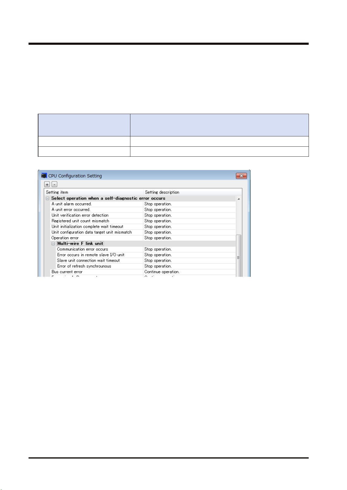
● If the registered slave unit starts during the wait time, the mode changes to RUN mode. The
mode can be switched. When turning on the power in RUN mode or switching the mode from
PROG. to RUN, the mode automatically changes to RUN mode.
● When the time until the registered slave unit starts exceeds the specified connection wait
time, an error occurs. At this time, the ERROR LED of the FP7 MW Unit turns on.
● The operation mode of the CPU unit when an error occurs depends on the setting of CPU
configuration (Select operation when a self-diagnostic error occurs: A unit error occurred).
Select operation when a self-
diagnostic error occurs: A unit
error occurred.
Operation when the startup time of the slave registered in "select
slave connection" exceeds the setting of connection wait time
Operation stops. A unit error occurs. The CPU unit stays in PROG. mode.
Operation continues. A unit error occurs. The CPU unit is changed to RUN mode.
CPU configuration menu
6.5 Starting MEWNET-F System
6-16 WUME-FP7MW-06

6.6 Checking Before Operation (Before Switching to RUN Mode)
6.6.1 Checking Communication State
● When slave units and the master unit communicate normally, the both COM.LEDs turn on.
The connected slave numbers can be confirmed by the operation monitor LEDs of the
master unit.
● Confirm that the COM.LEDs of the master unit and all slave units are on. Then, confirm if the
connected slave numbers are correct by the operation monitor LEDs of the master unit.
● For details of the operation monitor LEDs of the master unit, refer to "2.3 Operation Monitor
LEDs".
6.6 Checking Before Operation (Before Switching to RUN Mode)
WUME-FP7MW-06 6-17
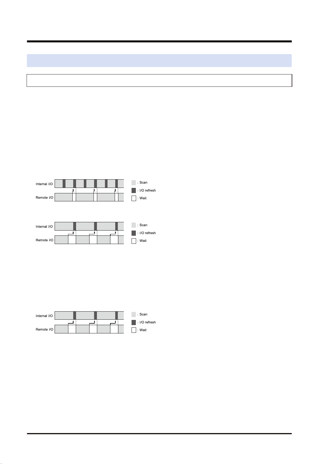
6.7 Behavior During Operation
6.7.1 Remote I/O Refresh
There are two remote I/O refresh methods.
● For "Synchronous refresh", remote I/Os are simultaneously updated with the normal I/Os of
the master unit system. When selecting "Synchronous refresh", the time taken for one scan
becomes longer as the number of remote I/Os increases.
● When selecting "Asynchronous refresh", remote I/Os are not simultaneously updated with
the normal I/Os, however, it can decrease the scan time for the normal I/Os.
■
Asynchronous refresh
● The normal I/O update (refresh) is performed after completing the processing of normal I/Os
even if remote I/O processing has not been completed yet.
● The remote I/O update (refresh) is performed after completing the processing of remote I/Os.
(Note 1) The above figure shows the operation when "Normal I/O scan time" is shorter than "Remote I/O scan
time".
(Note 1) The above figure shows the operation when "Normal I/O scan time" is longer than "Remote I/O scan
time". Even when selecting "Asynchronous refresh", the update is performed at the same timing as
that for "Synchronous refresh".
■
Synchronous refresh
● The normal I/O update (refresh) and remote I/O update (refresh) are performed after
completing the processing of normal I/Os and remote I/Os.
● When the time for scanning remote I/Os is long, the scan time relatively increases.
(Note 1) The above figure shows the operation when "Normal I/O scan time" is longer than "Remote I/O scan
time".
6.7 Behavior During Operation
6-18 WUME-FP7MW-06

7 Other Functions
7.1 Remote programming .........................................................................7-2
7.1.1 Overview .......................................................................................... 7-2
7.1.2 Operation of Tool Software .............................................................. 7-3
7.2 Computer Link.....................................................................................7-4
7.2.1 Overview .......................................................................................... 7-4
7.2.2 Specifications and Restrictions ........................................................ 7-4
7.3 Hierarchy Link.....................................................................................7-6
7.3.1 Overview .......................................................................................... 7-6
7.3.2 Specifications and Restrictions ........................................................ 7-7
7.4 Relevant Information...........................................................................7-9
7.4.1 Format of [LC] Command Response ............................................... 7-9
7.4.2 Format of [0C] Command Response ............................................... 7-10
WUME-FP7MW-06
7-1
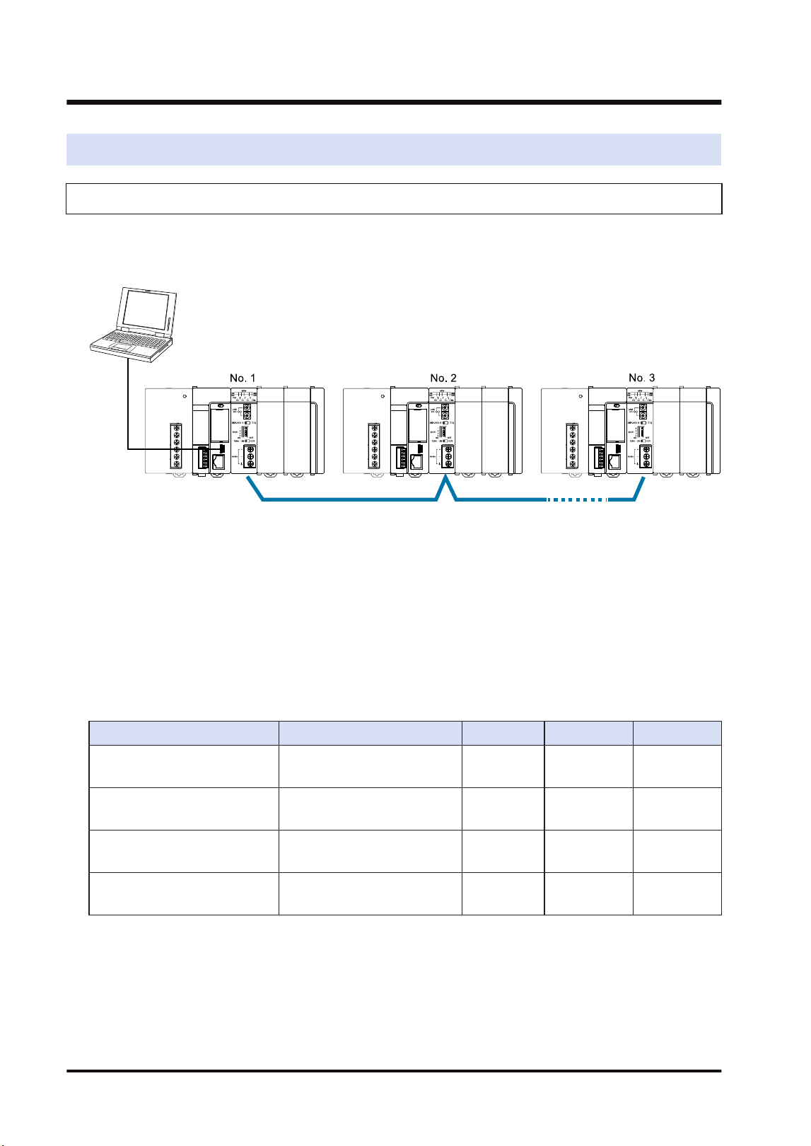
7.1 Remote programming
7.1.1 Overview
This function enables PLCs in the same system connected to the network to be programmed by
tool software remotely. For the system which uses FP7 MW Unit, it can be executed under the
following conditions.
■
Remote programming function
● By connecting a PC to the USB port or COM0 port of FP7 CPU Unit, operation is performed
by the tool software via the network.
● To operate the remote FP7, it must be connected by the MEWNET-W2.
● To operate remote FP series PLCs (such as FP2SH), either MEWNET-W2 or MEWNET-W
must be connected.
● The remote FP7 cannot be operated from a PC connected to conventional models FP2/
FP2SH.
■
Combination (A: Available, Blank: Not available)
PC connection port Programmed PLC W mode W2 mode Remarks
FP7
(USB port/COM0 port)
FP7 A
(Note 1)
FP7
(USB port/COM0 port)
FP2/FP2SH A A
FP2/FP2SH
(Tool port/COM port)
FP2/FP2SH A A
FP2/FP2SH
(Tool port/COM port)
FP7
(Note 2)
(Note 1) As the W mode is not available for MEWTOCOL7, remote programming cannot be performed.
(Note 2) As the models other than FP7 does not support MEWTOCOL7, remote programming cannot be
performed.
7.1 Remote programming
7-2 WUME-FP7MW-06
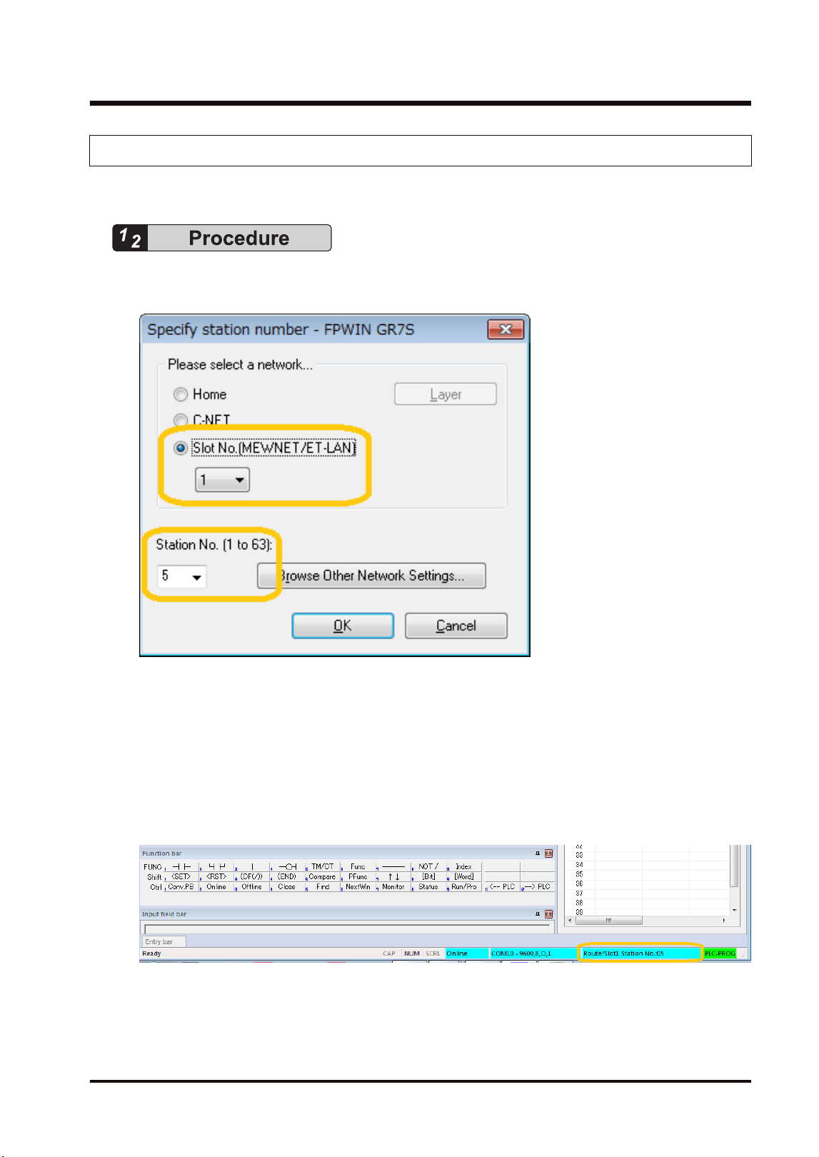
7.1.2 Operation of Tool Software
This section describes the procedure for performing remote programming from FPWIN GR7.
1. Select Online>Communication Settings from the menu bar.
The "Communication Settings" dialog box is displayed.
2. Select "Slot Number (MEWNET/ET-LAN)" and the slot number of the home unit in which
the FP7 MW Unit is installed.
3. Select the unit number of a PLC to be remotely programmed.
4. Press the [[OK]] button.
The slot number and unit number of the connected communicating unit is displayed on the
right side of the status field. After that, remote programming operation can be performed for
the communicating unit, such as uploading/downloading projects, monitoring devices, and
monitoring statuses.
7.1 Remote programming
WUME-FP7MW-06 7-3
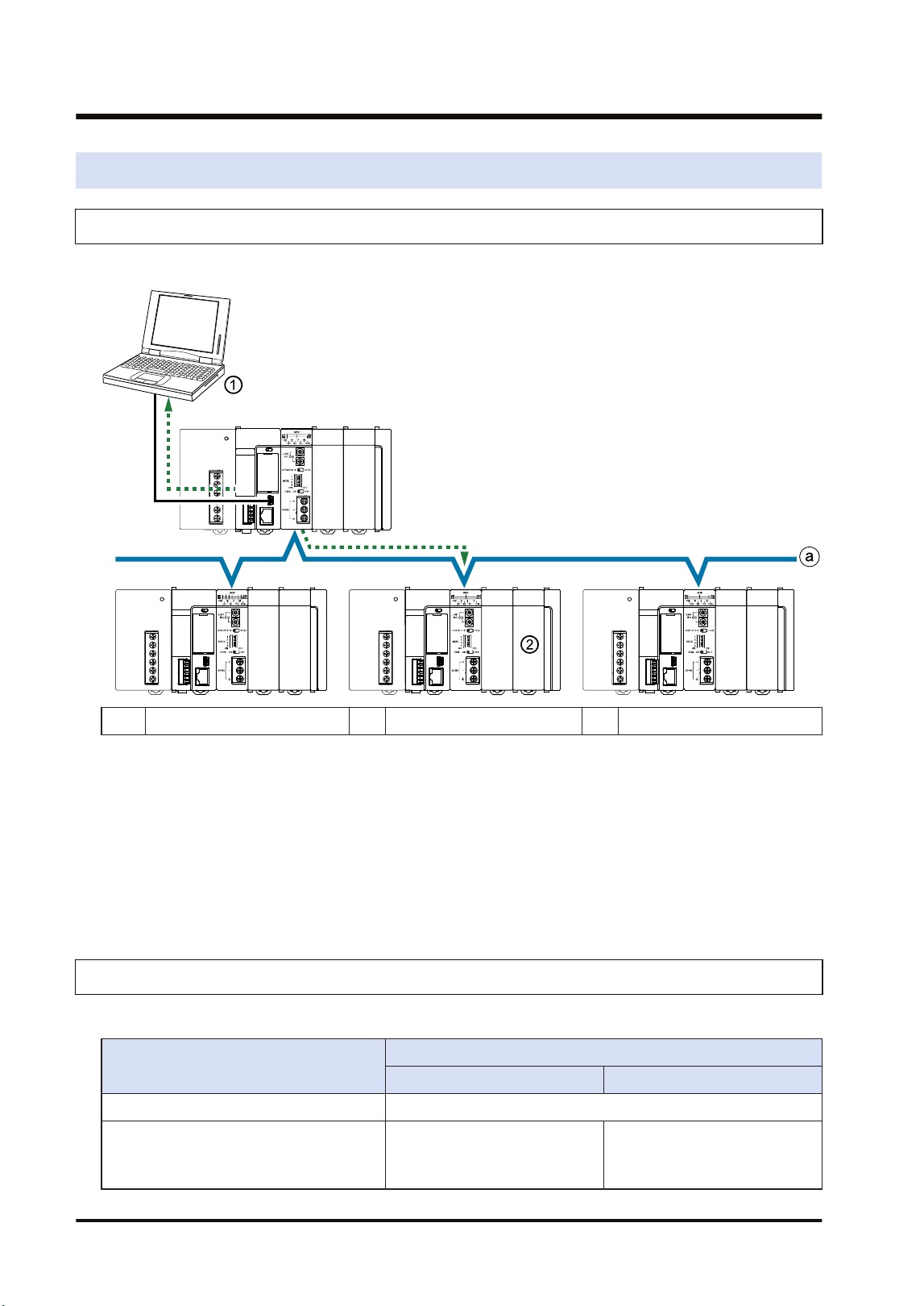
7.2 Computer Link
7.2.1 Overview
This figure shows an example when a command is sent/received to/from a higher-order PC.
(1) Source (2) Destination (3) Depth 0
■
Computer Link Function
● Communication is performed by sending commands and receiving responses from a higher-
order PC or higher-order PLC. Various operations such as reading and writing operation
devices can be performed.
● The communication is performed according to the format of MEWTOCOL-COM or
MEWTOCOL7.
● Destination PLCs need no user programs for communication.
7.2.2 Specifications and Restrictions
Usable protocols and capacity vary according to the mode.
Item
Specifications
W mode W2 mode
Number of units Max. 32 units
Supported protocol MEWTOCOL-COM
MEWTOCOL-COM
MEWTOCOL7
(Note 1)
7.2 Computer Link
7-4 WUME-FP7MW-06

Item
Specifications
W mode W2 mode
Computer link capacity Max. 118 bytes per frame Max. 2048 bytes per frame
(Note 1) For sending commands using MEWTOCOL7, PLCs must consists of FP7 only.
7.2 Computer Link
WUME-FP7MW-06 7-5
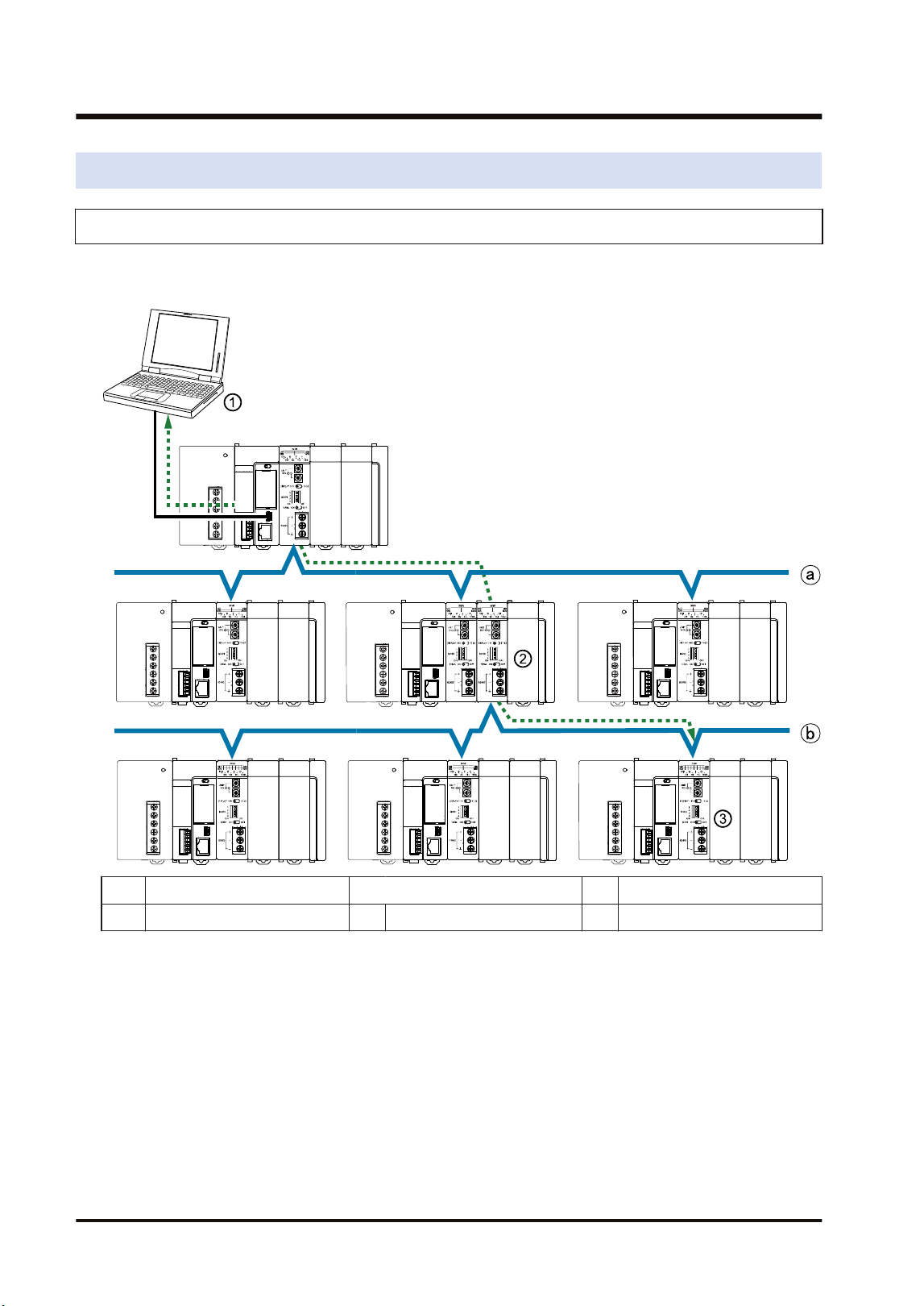
7.3 Hierarchy Link
7.3.1 Overview
This figure shows an example when a command is sent/received to/from a higher-order PC via
a relay station.
(1) Source (a) Depth 0
(2) Relay station (3) Destination (b) Depth 1
■
Hierarchy link function
● Commands can be sent or received to link with PLCs in different hierarchies using a PLC
with multiple link units as a relay station.
● The system using the FP7 MW Unit can consist of PLCs in a maximum of two hierarchies
(depth 0 or depth 1).
● For the hierarchy link, linked PLCs are specified by the hierarchy control command "LC" of
communication procedure "MEWTOCOL-COM". After sending the hierarchy control
command "LC", PLCs are controlled by sending/receiving MEWTOCOL commands
according to used applications.
● In the system using the FP7 MW Unit, the transmission path information is held in case of
power outage. Even after the occurrence of an instantaneous power failure, operation can be
7.3 Hierarchy Link
7-6 WUME-FP7MW-06
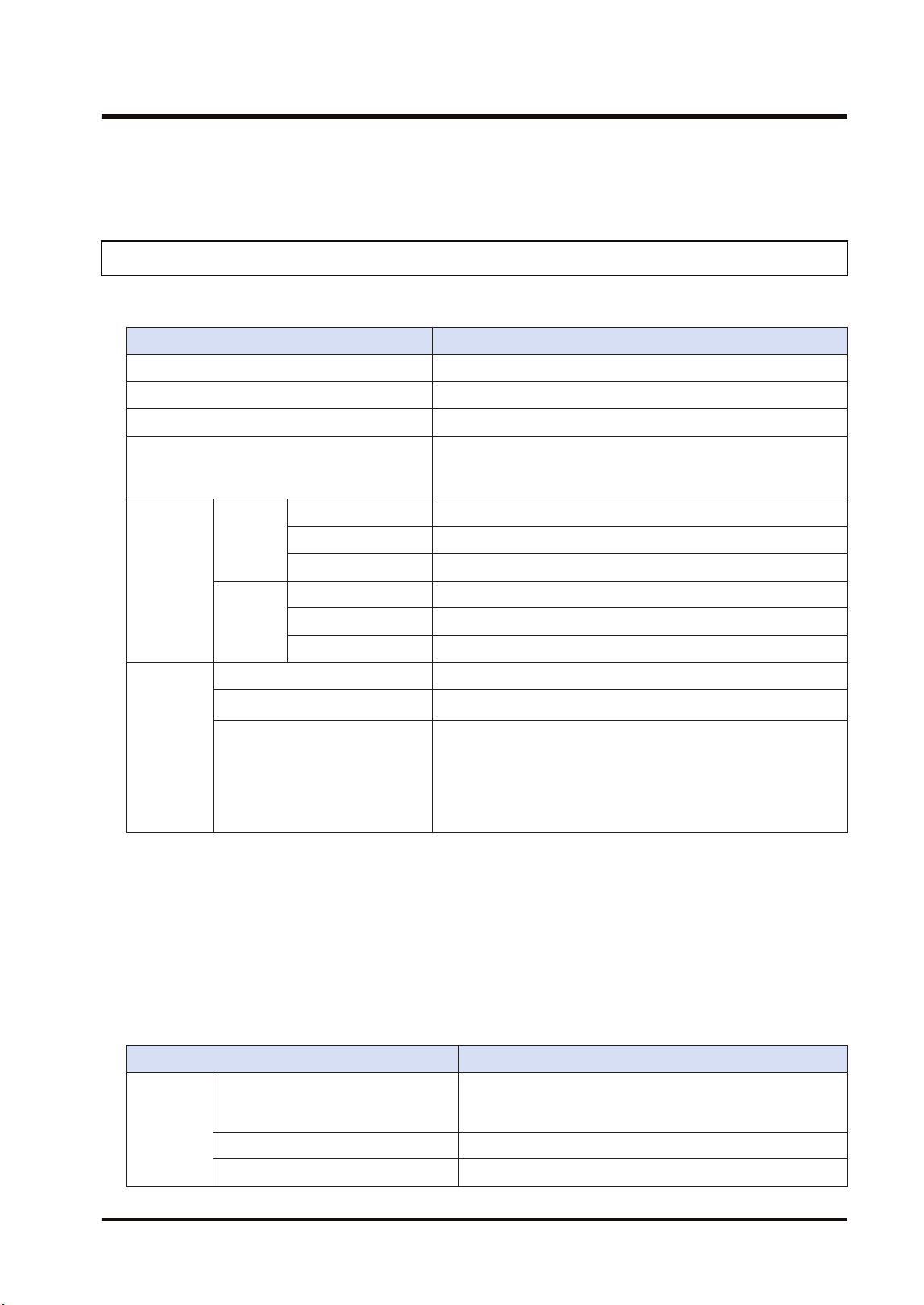
continued. Send the hierarchy control command "LC" again for communicating with PLCs in
different hierarchies.
7.3.2 Specifications and Restrictions
■
Specifications
Item Specifications
Supported function Computer Link
Hierarchy Max. 2 hierarchies (Depth 0, depth 1)
Corresponding port of CPU unit USB port / COM0 port
Transmission path setting function
Set it to the PLC communication port by MEWTOCOL-COM
command (0C, LC). The transmission path information is held
in case of power outage.
(Note 2)(Note 3)
Protocol
and size
capable of
relaying
W mode
MEWTOCOL7 Not available
MEWTOCOL-COM 118 bytes per frame
MEWTOCOL-DAT 118 bytes per frame
W2 mode
MEWTOCOL7 4 k bytes per frame
MEWTOCOL-COM 2 k bytes per frame
MEWTOCOL-DAT 2 k bytes per frame
Available
transmissio
n path
Source -> (Relay station) -> Destination
MEWTOCOL7
(Note 4)
FP7(FP7)FP7FP7→(FP7)→FP7
MEWTOCOL-COM
MEWTOCOL-DAT
(Note 1)(Note 5)
FP7(FP7)FP7FP7→(FP7)→FP7
FP7→(FP2)→FP7
FP7→(FP2)→FP2
FP2→(FP2)→FP7
FP2→(FP7)→FP7
(Note 1) The remote programming function and data transfer function (transfer by SEND/RECV instructions)
are available for PLCs in the same hierarchy (depth 0). They cannot be executed for PLCs in the
different hierarchy (depth 1).
(Note 2) Slot numbers are set in the range of 01h to 10h (1 to 16).
(Note 3) The relay position for the FP7 CPU is specified with a slot number. The depth is selected from 0 or 1.
(Note 4) For communicating with MEWTOCOL7, the system must consist of MEWNET-W2 and FP7 only.
(Note 5) Data must be sent by the minimum size limited in the transmission path.
■
Other restrictions
Item Specifications
Unit
configuratio
n
Relay from W mode to W mode
Available only when the units in W mode are two. When
there are more than three units, it cannot be used as the
relay station.
Relay from W mode to W2 mode Not available
Relay from W2 mode to W mode Not available
7.3 Hierarchy Link
WUME-FP7MW-06 7-7

Item Specifications
Relay from W2 mode to W2 mode
There is no restrictions when the installed units are up to 4
units (i.e. max. connectable number of units).
Relay to the built-in ET-LAN in the
CPU
Not available
Simultaneous transmission of commands
Communication cannot be performed when another
command for the same function (computer link, data
transfer, remote programming) is sent to the same relay
station
7.3 Hierarchy Link
7-8 WUME-FP7MW-06
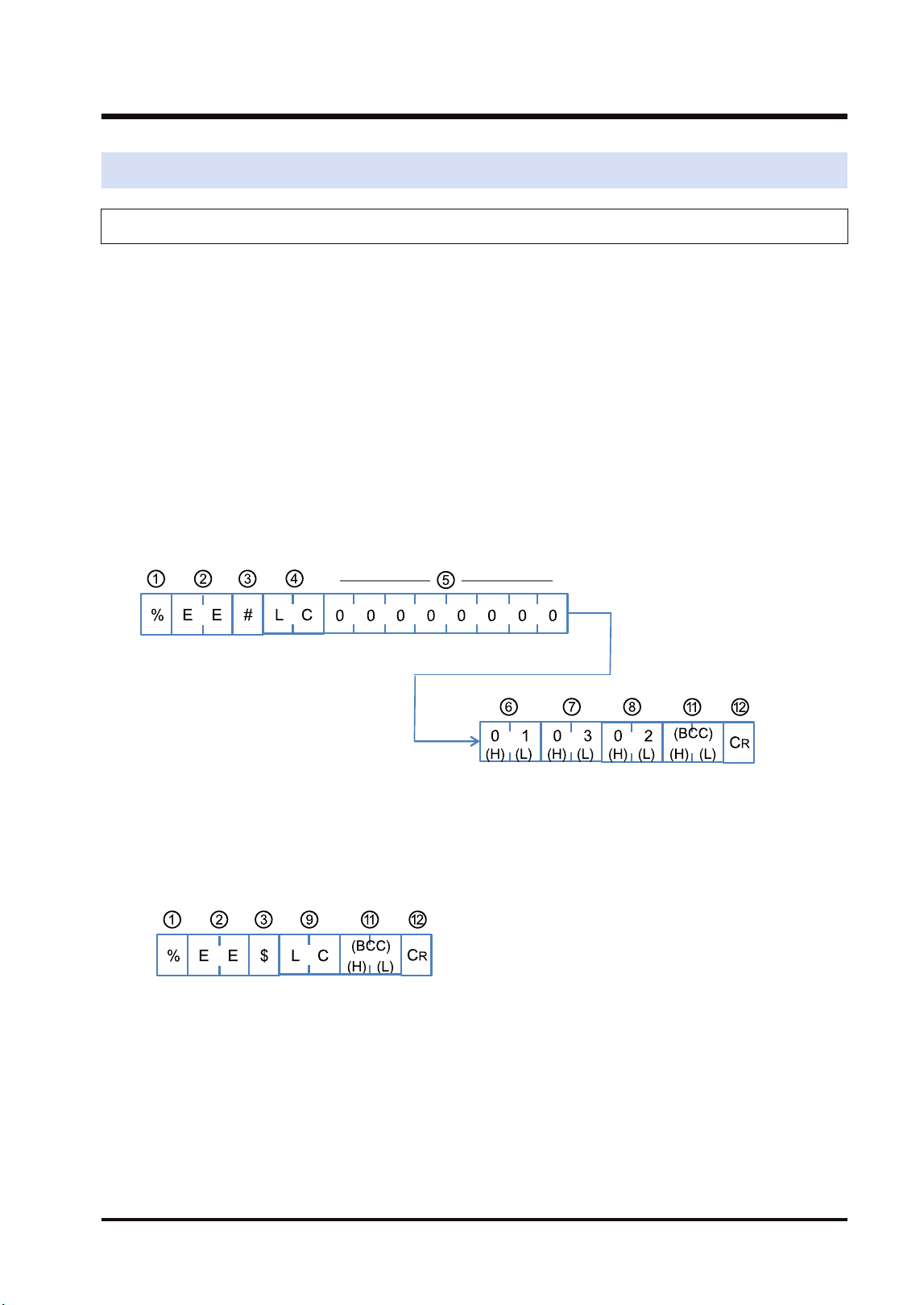
7.4 Relevant Information
7.4.1 Format of [LC] Command Response
This section describes the formats of "LC: Hierarchy control" used for the hierarchy link
function.
■
Overview
● Specify hierarchies and register the units to be linked in the PLC.
● In the system using the FP7 MW Unit, the transmission path information is held in case of
power outage. Even after the occurrence of an instantaneous power failure, operation can be
continued.
● Send the hierarchy control command "LC" again for communicating with PLCs in different
hierarchies.
■
Command format
Format when using the FP7 MW Unit
■
Response format (in normal state)
"LC" that is the same as the command code is returned on successful completion.
■
Response format (in abnormal state)
An error code is returned when the operation abnormally ends.
7.4 Relevant Information
WUME-FP7MW-06 7-9
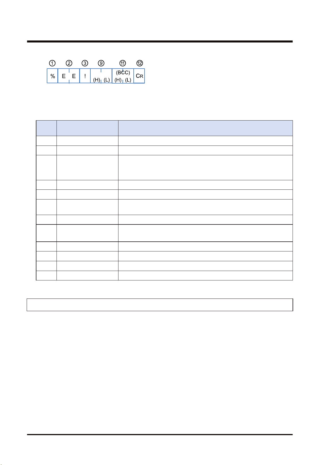
■
Elements which compose command responses
Numb
er
Name Description
(1) Header % or <
(2) Address "EE" (Fixed): Specify the own unit.
(3) Identification code
"#": Indicates a command.
"$": Indicates a normal response.
"!": Indicates an error response.
(4) Command code "LC": Indicates the hierarchy control command.
(5) 0 (Fixed) "0" x 8 characters of LC command are given.
(6) Depth
"00" to "01": Specify the depth to a connected unit. For the FP7 MW Unit,
up to the depth 1 can be specified.
(7) Relay source unit no. "01" to "32": Specify a relay source unit number.
(8) Relay destination slot no.
"0x01" to "0x10": For the FP7 MW Unit, specify slot numbers.
Specify slot numbers (01 to 16) converted to hexadecimal.
(9) Response code "LC": It is returned for a normal response.
(10) Error code An error code is returned when an error occurs.
(11) Check code BCC code is stored.
(12) Terminator ”CR” (0D:Hex):
7.4.2 Format of [0C] Command Response
This section describes the formats of "0C: Access link unit" used for the hierarchy link function.
■
Overview
● Register units to be linked in the PLC.
● When this command is received, the transmission path information set by "LC: Hierarchy
control" command will be invalid.
● In the system using the FP7 MW Unit, the transmission path information is held in case of
power outage. Even after the occurrence of an instantaneous power failure, operation can be
continued.
● The transmission path information is initialized (cleared to 0) by specifying "00" for a slot
number.
■
Command format
Format when using the FP7 MW Unit
7.4 Relevant Information
7-10 WUME-FP7MW-06
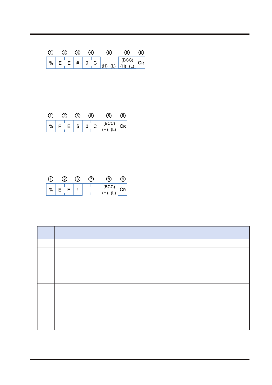
■
Response format (in normal state)
"0C" that is the same as the command code is returned on successful completion.
■
Response format (in abnormal state)
An error code is returned when the operation abnormally ends.
■
Elements which compose command responses
Numb
er
Name Description
(1) Header % or <
(2) Destination "EE" (Fixed): Specify the own unit.
(3) Identification code
"#": Indicates a command.
"$": Indicates a normal response.
"!": Indicates an error response.
(4) Command code "0C": Indicates the access link unit command.
(5) Slot no.
"0x01" to "0x10": For the FP7 MW Unit, specify slot numbers.
Specify slot numbers (01 to 16) converted to hexadecimal.
(6) Response code "0C": It is returned for a normal response.
(7) Error code An error code is returned when an error occurs.
(8) Check code BCC code is stored.
(9) Terminator ”CR” (0D:Hex)
7.4 Relevant Information
WUME-FP7MW-06 7-11

(MEMO)
7-12 WUME-FP7MW-06

8 Troubleshooting
8.1 Self-diagnostic Function......................................................................8-2
8.1.1 Operation Monitor LEDs of CPU Unit .............................................. 8-2
8.1.2 Operation State of CPU Unit When an Error Occurs ....................... 8-2
8.1.3 Operation Monitor LEDs of FP7 MW Unit ........................................ 8-3
8.2 Confirmation by System Relays / System Data Registers..................8-4
8.2.1 Confirmation by System Registers................................................... 8-4
8.2.2 Confirmation by System Data Registers .......................................... 8-4
8.3 Monitor and Operation by User Programs ..........................................8-6
8.3.1 Monitoring Status by PMGET Instruction......................................... 8-6
8.3.2 Clearing Errors by ERR Instruction.................................................. 8-7
8.4 What to Do If an Error Occurs.............................................................8-8
8.4.1 When Transmission Error Occurs (COM.LED of FP7 MW Unit
Turns Off).......................................................................................... 8-8
8.4.2 When ERR LED on FP7 MW Unit Turns ON ................................... 8-8
8.4.3 When ERR LED on FP7 MW Unit is Flashing ................................. 8-8
WUME-FP7MW-06
8-1
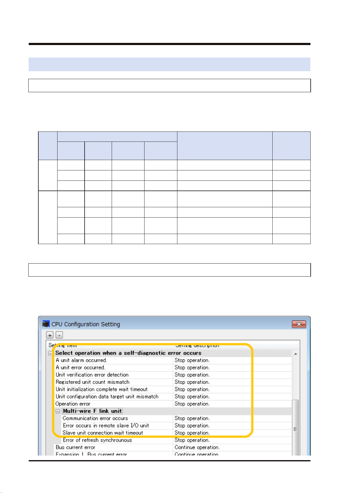
8.1 Self-diagnostic Function
8.1.1 Operation Monitor LEDs of CPU Unit
The CPU unit has a self-diagnostic function which identifies errors and stops operation if
necessary. Indications concerning self-diagnosis are as follows.
■
LEDs related to self-diagnostic errors
LEDs of CPU Unit
Description
Operation
status
RUN
Green
PROG
Green
ERROR
Red
ALARM
Red
Norm
al
opera
tion
ON OFF OFF OFF Normal operation Operating
OFF ON OFF OFF Program mode Stop
Flashes OFF OFF OFF Forcing input/output in RUN mode Operating
Error
ON OFF Flashes OFF Self-diagnostic error (During
operation)
Operating
OFF ON Flashes OFF Self-diagnostic error (During stop) Stop
OFF ON (Not fixed) ON System watchdog timer has been
activated
Stop
OFF Flashes (Not fixed) OFF Waiting for connection of slaves Stop
8.1.2 Operation State of CPU Unit When an Error Occurs
Operation mode of the CPU unit at the time of error can be set (Continue or Stop) in the "FP7
Configuration" dialog box of the programming tool FPWIN GR7.
■
Configuration menu of FPWIN GR7
8.1 Self-diagnostic Function
8-2 WUME-FP7MW-06
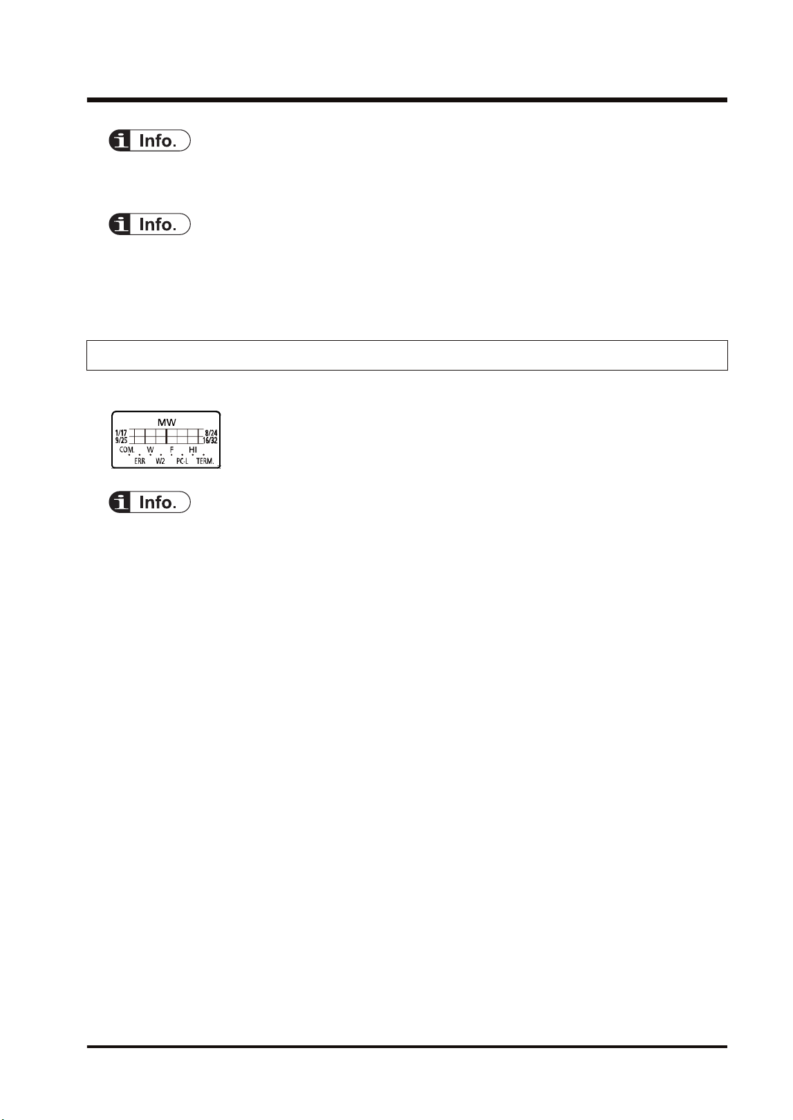
● For information on the troubleshooting for the CPU unit, also refer to FP7 CPU Unit User's
Manual (Hardware).
● In W mode or W2 mode, the CPU unit continues the operation even if an error occurs in the
FP7 MW Unit (except for the hardware error of the FP7 MW Unit).
● In F mode, the operation mode is determined by "CPU Configuration Setting".
8.1.3 Operation Monitor LEDs of FP7 MW Unit
The FP7 MW Unit has a self-diagnostic function which identifies errors.
● For details of the operation monitor LEDs of the FP7 MW Unit, refer to "2.3 Operation Monitor
LEDs".
8.1 Self-diagnostic Function
WUME-FP7MW-06 8-3
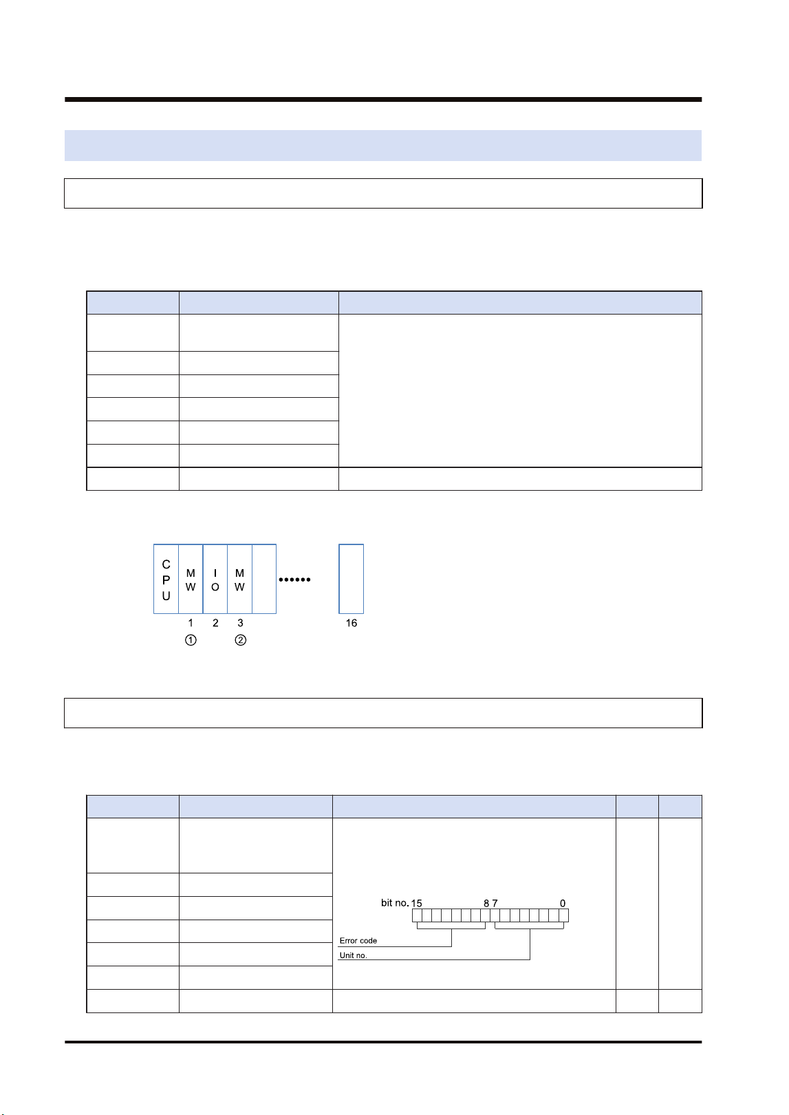
8.2 Confirmation by System Relays / System Data Registers
8.2.1 Confirmation by System Registers
The system relay of the relative number of an abnormal unit among installed FP7 MW Units
turns on.
SR50-SR5F
Relay no. Name Description
SR50 FP7 MW Unit error
annunciation relay (1st unit)
Turns on when an error occurs in the FP7 MW Unit.
The error code and unit number is stored in the system registers
SD90-SD95.
SR51 (2nd unit)
SR52 (3rd unit)
SR53 (4th unit)
SR54 (5th unit)
SR55 (6th unit)
SR56-SR5F Reserved for system
(Note 1) The unit numbers in the above table are those for the installed FP7 MW Units (W mode/W2 mode/F
mode) counted from the unit closest to the CPU unit. They are different from the slot numbers.
8.2.2 Confirmation by System Data Registers
The following is a list of system data registers (SD) related to the FP7 MW Unit.
SD90-SD99 (A: Available, Blank: Not available)
Register No. Name Description R W
SD90
FP7 MW Unit error
annunciation register
(1st unit)
When an error occurs in the FP7 MW Unit, the
error code is stored in the high byte and the unit
number is stored in the low byte.
A
SD91 (2nd unit)
SD92 (3rd unit)
SD93 (4th unit)
SD94 (5th unit)
SD95 (6th unit)
SD96-SD99 Reserved for system
8.2 Confirmation by System Relays / System Data Registers
8-4 WUME-FP7MW-06

(Note 1) The following values are stored in the error code and unit number.
Network Error code Unit No.
MEWNET-W
bit 8 Transmission system
error
H01 to H20 (U1 to U32)
bit 9 Unit number duplicate
bit10 PLC link address
duplicate
bit11 Unit number error
bit12 Undefined
bit13 Undefined
bit14 Undefined
bit15 Undefined
MEWNET-W2
bit 8 Link unit stopped
H01 to H40 (U1 to U64)
bit 9 Link disabled
bit10 Undefined
bit11 Packet transmission
disabled
bit12 PLC link address
duplicate
bit13 Undefined
bit14 Undefined
bit15 Undefined
MEWNET-F
bit 8 Line error
H00 (Fixed)
bit 9 Transmission error
bit10 Prohibited unit
bit11 Terminal unit error
bit12 Excessive number of
slots
bit13 Excessive number of I/O
points
bit14 Instantaneous power
failure
bit15 Verification error
8.2 Confirmation by System Relays / System Data Registers
WUME-FP7MW-06 8-5
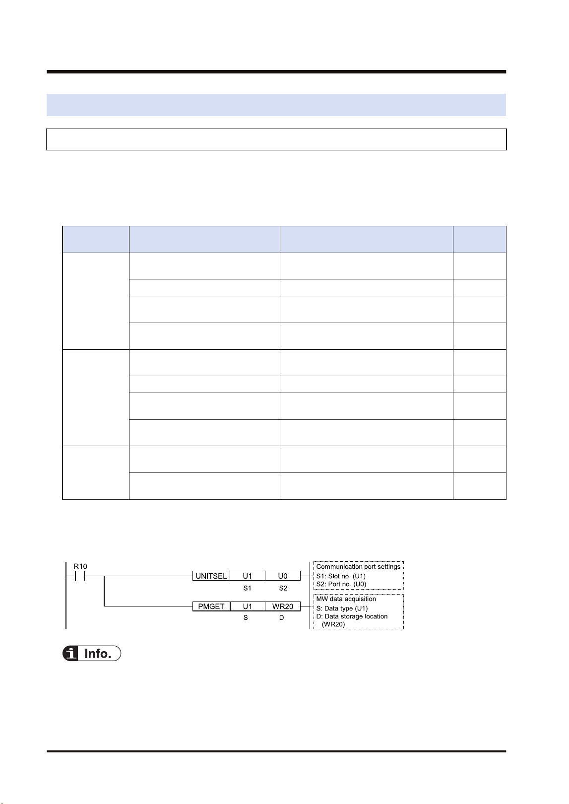
8.3 Monitor and Operation by User Programs
8.3.1 Monitoring Status by PMGET Instruction
The communication state or error information on the unit can be monitored by using PMGET
instruction. Readable type of information and the number of wards vary according to the
network mode.
■
Monitorable items
Mode Item Description No. of
words
MEWNET-W
PLC link communication state
The transmission state and operation
mode of PLC link are stored.
3
Network participation state The network participation state is stored. 3
Detail of W link communication error
The number of occurred communication
errors is stored.
15
PLC link refresh operation
monitoring information
The transmission/reception state of PLC
link is stored.
8
MEWNET-W2
PLC link transmission state
The transmission state and operation
mode of PLC link are stored.
6
Network participation state The network participation state is stored. 5
W2 link error system counter type
error area
The number of occurred communication
errors is stored.
18
W2 link error system error register
area
The error history is stored. U10
MEWNET-F
No. of F link services
The number of services of master unit is
stored.
1
F link operation state monitor
The information on connected unit and
abnormal units is stored.
U10
■
Example of program
This program is for acquiring the state of the unit connected to the network of the FP7 MW Unit
in the slot number 1.
● For checking communication parameters with PMGET instruction, the CPU should be set in the
RUN mode. For MEWNET-F, the operation stops according to errors and changes to PROG.
mode. As necessary, set "Mode selection when self-diagnostic error occurs - A unit error
occurred." to "Continue operation" in the "CPU configuration".
8.3 Monitor and Operation by User Programs
8-6 WUME-FP7MW-06
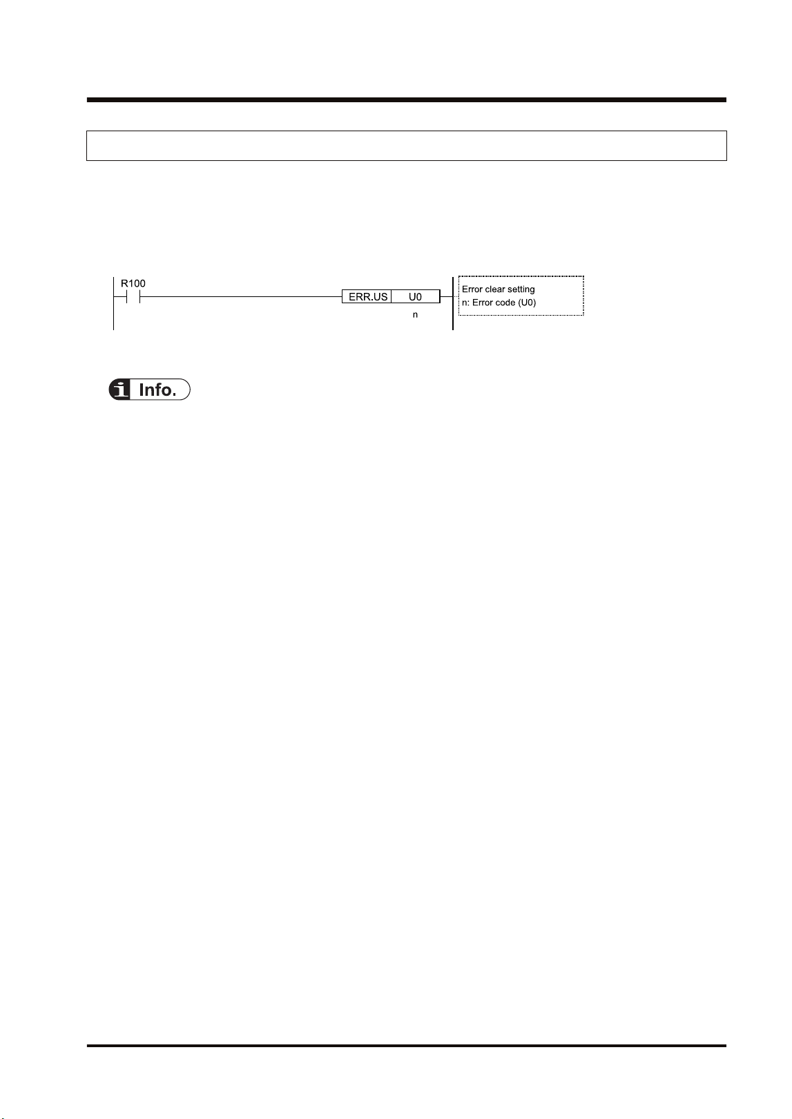
8.3.2 Clearing Errors by ERR Instruction
The self-diagnostic errors in the FP7 MW Unit can be cleared by user programs. After
correcting error factors, execute the clear operation.
■
Sample program
When clearing the self-diagnostic error code, the errors in the FP7 MW Unit are also cleared.
● For details of "PMGET" instructions, refer to "9.1.3 PMGET Instruction (For MEWNET-W)",
"9.1.4 PMGET Instruction (For MEWNET-W2)", and "9.1.5 PMGET Instruction (For MEWNET-
F)".
● For details of "ERR" instructions, refer to "9.2.1 ERR Instruction".
8.3 Monitor and Operation by User Programs
WUME-FP7MW-06 8-7

8.4 What to Do If an Error Occurs
8.4.1 When Transmission Error Occurs (COM.LED of FP7 MW Unit Turns Off)
■
Situation
A transmission error may have occurred.
■
Procedure (1)
Check to make sure the transmission cables have been connected between the two (+)
terminals, and between the two (-) terminals of the units.
■
Procedure (2)
Check if the transmission cables are within the specifications range. Configure all the wiring
systems using the same type of cables. Do not mix different types of cables.
■
Procedure (3)
Check the operation monitor LEDS and terminator setting switch on the unit to make sure the
units at the both ends of the network are set as terminal units.
8.4.2 When ERR LED on FP7 MW Unit Turns ON
■
Situation
An error may have occurred in the hardware of FP7 MW Unit.
■
Procedure
Turn off and on the power, and check again.
8.4.3 When ERR LED on FP7 MW Unit is Flashing
■
Situation
Any setting or configuration of the unit may be wrong.
■
Procedure
Confirm the position of the unit and error content by using any of the followings.
● System relays (SR), System data registers (SD)
● Status information (such as transmission assurance relay, operation mode relay)
● PMGET instruction
■
Procedure
Correct the settings and configuration of the unit.
8.4 What to Do If an Error Occurs
8-8 WUME-FP7MW-06

■
Check items
Item Contents to check Remarks
Switch settings
Is the selection of the mode switch (W mode/W2 mode/F mode)
correct?
For the PLC link, is the mode switch number 1 off?
Are the unit numbers set correctly?
Isn't there any overlapping unit number?
Configuration
Is the allocation of PLC link correct?
Isn't there any overlapping transmission area for connected units.
Is the transmission/reception area of PLC link correct?
When unit numbers are set in Configuration, are unit numbers set
correctly?
Isn't there any overlapping unit number?
User program
When unit numbers are set by user programs, are unit numbers set
correctly?
(W mode) When performing the PLC link allocation by user programs,
is the PLC link allocation correct?
(Note 1) For checking communication parameters with PMGET instruction, the CPU should be set in the RUN
mode.
8.4 What to Do If an Error Occurs
WUME-FP7MW-06 8-9

(MEMO)
8-10 WUME-FP7MW-06

9 Instruction References
9.1 Communication Instructions................................................................9-2
9.1.1 SEND Instruction (When Using FP7 MW Unit) ................................ 9-2
9.1.2 RECV instruction (When using FP7 MW Unit)................................. 9-3
9.1.3 PMGET Instruction (For MEWNET-W) ............................................ 9-5
9.1.4 PMGET Instruction (For MEWNET-W2) .......................................... 9-8
9.1.5 PMGET Instruction (For MEWNET-F).............................................. 9-11
9.1.6 PMSET/pPMSET Instruction (For MEWNET-W) ............................. 9-12
9.1.7 PMSET/pPMSET Instruction (For MEWNET-W2) ........................... 9-14
9.2 Special Instructions.............................................................................9-16
9.2.1 ERR Instruction................................................................................ 9-16
WUME-FP7MW-06 9-1
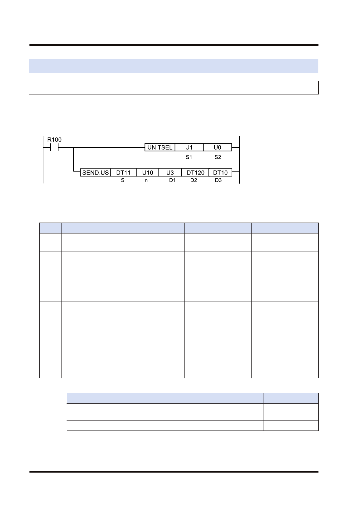
9.1 Communication Instructions
9.1.1 SEND Instruction (When Using FP7 MW Unit)
Data can be transferred from the own unit to destination units between PLCs connected by
MEWNET-W or MEWNET-W2 by specifying the both operation devices.
■
Instruction format
(Note 1) The above figure shows the case that the FP7 MW Unit of S1=U1 (slot no.1) is specified by UNITSEL
instruction.
■
Operand
Item Settings Settable device Setting range
S
Specify the starting address of the source data
area.
(Note 1)
WX, WY, WR, WL, DT,
LD, X, Y, R, L, DT.n, LD.n
-
n
Specify the number of sent data.
(Note 2)
WX, WY, WR, WL, DT,
LD, U, H
(For register
transmission)
W mode: 1 to 55
W2 mode: 1 to 1020
(For bit transmission)
1 (Fixed)
D1 Specify the destination unit number.
WX, WY, WR, WL, DT,
LD, U, H
W mode: 1 to 32
W2 mode: 1 to 64
D2
Specify the starting address of the device in the
destination data area of destination unit.
(Note 3)
WX, WY, WR, WL, DT,
LD, X, Y, R, L
(For register
transmission)
0 to 65535
(For bit transmission)
0 to 65535F
D3
Specify the device area of the local unit storing
the execution result code (1 word).
WX,WY,WR,WL,DT,LD -
(Note 1) The transfer method varies according to the device type specified for operands [S] and [D2].
Devices specified for [S] and [D2] Transfer method
16-bit device: WX, WY, WR, WL, DT, LD Register
transmission
1-bit device: X, Y, R, L, DT.n, LD.n Bit transmission
(Note 2) The number of sent data is in word unit for the register transmission and it is in bit unit for the bit
transmission.
(Note 3) When the destination unit is FP7, only global devices can be specified. Local devices cannot be
specified.
9.1 Communication Instructions
9-2 WUME-FP7MW-06

(Note 4) When the destination data is FL, specify the integer (U, H). (For FL100, specify U100.)
■
Execution result code [D3]
Code Description Code Description
H0 Normal end H24 Transmission format error
H 1
The communication port is being used in
the master communication.
H25 MW hardware error
H 2
The communication port is being used in
the slave communication.
H26 The unit number setting error occurs.
H 3
The number of master communication
instructions simultaneously used is
exceeded.
H27 NOT support
H 4 Transmission timeout H28 No response
H 5 Response reception timeout H29 MW hardware error
H 6
Reception error
(Note 1)
H30 Transmission timeout error
H7
I/O allocation shortage error
(Note 2)
H30-H39 MW hardware error
H8 The send buffer is being used.
H9 Own unit unset error H41 Format error
H21 NACK H60 Parameter error
H22 WACK H61 Data error
H23 The unit number duplicate error occurs. H91 Missing expansion slave unit error
(Note 1) It occurs when an abnormal telegram is received. When the format of the header for each protocol is
abnormal, the reception data will be discarded and the response reception will time out.
(Note 2) It occurs when the communication control I/O relays corresponding to the communication port (master
communication clear to send flag, master communication send active flag, master communication
send done result relay) are not allocated as I/O words of the CPU unit in the I/O map. It occurs only
when the number of user connections of ET-LAN is expanded and this instruction is executed
specifying that expanded connections.
■
Precautions during programming
● Describe UNITSEL instruction immediately before SEND instruction and specify the slot
number of FP7 MW Unit in [S1] and 0 in [S2].
● For FP7 MW Unit, SEND instruction executes the transmission and reception by
MEWTOCOL-DAT (fixed).
● Up to 16 send instructions can be performed to different COM ports and connections
simultaneously. (The total of simultaneous usage of SEND, RECV, pGPSEND, GPTRNS,
and pPMSET instructions.)
● For the FP7 MW Unit, only one of those can be executed for one unit.
9.1.2 RECV instruction (When using FP7 MW Unit)
Data can be transferred from the destination unit to own unit between PLCs connected by
MEWNET-W or MEWNET-W2 by specifying the both operation devices.
9.1 Communication Instructions
WUME-FP7MW-06 9-3
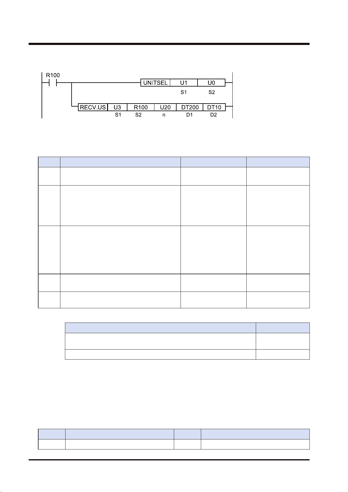
■
Instruction format
(Note 1) The above figure shows the case that the FP7 MW Unit of S1=U1 (slot no.1) is specified by UNITSEL
instruction.
■
Operand
Item Settings Settable device Setting range
S1 Specify the destination unit number.
WX, WY, WR, WL, DT,
LD, U, H
W mode: 1 to 32
W2 mode: 1 to 64
Examp
le 1
Specify the starting address of the device in the
source data area of destination unit.
(Note 1)(Note
2)(Note 3)(Note 4)
WX, WY, WR, WL, DT,
LD, U, H
X, Y, R, L, DT.n, LD.n
(For register
transmission)
0 to 65535
(For bit transmission)
0 to 65535F
n
Specify the number of received data.
(Note 5)
WX, WY, WR, WL, DT,
LD, U, H
(For register
transmission)
W mode: 1 to 56
W2 mode: 1 to 1020
(For bit transmission)
1 (Fixed)
D1
Specify the device starting address in the home
unit storing received data.
(Note 1)
WX, WY, WR, WL, DT,
LD, X, Y, R, L, DT.n, LD.n
(Note 1)
D2
Specify the device area of the local unit storing
the execution result code (1 word).
WX,WY,WR,WL,DT,LD -
(Note 1) The transfer method varies according to the device type specified for operands [S2] and [D1].
Device specified in [S2] and [D1] Transfer method
16-bit device: WX, WY, WR, WL, DT, LD Register
transmission
1-bit device: X, Y, R, L, DT.n, LD.n Bit transmission
(Note 2) The bit devices DT, n, LD and n cannot be specified for the starting address of the source data of
destination unit.
(Note 3) When the source unit is FP7, only global devices can be specified. Local devices cannot be specified.
(Note 4) When the source data is FL, specify the integer (U, H). (For FL100, specify U100.)
(Note 5) The number of sent data is in word unit for the register transmission and it is in bit unit for the bit
transmission.
■
Execution result code [D2]
Code Description Code Description
H0 Normal end H24 Transmission format error
9.1 Communication Instructions
9-4 WUME-FP7MW-06

Code Description Code Description
H 1
The communication port is being used in
the master communication.
H25 MW hardware error
H 2
The communication port is being used in
the slave communication.
H26 The unit number setting error occurs.
H 3
The number of master communication
instructions simultaneously used is
exceeded.
H27 NOT support
H 4 Transmission timeout H28 No response
H 5 Response reception timeout H29 MW hardware error
H 6
Reception error
(Note 1)
H30 Transmission timeout error
H7
I/O allocation shortage error
(Note 2)
H30-H39 MW hardware error
H8 The send buffer is being used.
H9 Own unit unset error H41 Format error
H21 NACK H60 Parameter error
H22 WACK H61 Data error
H23 The unit number duplicate error occurs. H91 Missing expansion slave unit error
(Note 1) It occurs when an abnormal telegram is received. When the format of the header for each protocol is
abnormal, the reception data will be discarded and the response reception will time out.
(Note 2) It occurs when the communication control I/O relays corresponding to the communication port (master
communication clear to send flag, master communication send active flag, master communication
send done result relay) are not allocated as I/O words of the CPU unit in the I/O map. It occurs only
when the number of user connections of ET-LAN is expanded and this instruction is executed
specifying that expanded connections.
■
Precautions during programming
● Describe UNITSEL instruction immediately before RECV instruction and specify the slot
number of FP7 MW Unit in [S1] and 0 in [S2].
● For FP7 MW Unit, RECV instruction executes the transmission and reception by
MEWTOCOL-DAT (fixed).
● Up to 16 send instructions can be performed to different COM ports and connections
simultaneously. (The total of simultaneous usage of SEND, RECV, pGPSEND, GPTRNS,
and pPMSET instructions.)
● For the FP7 MW Unit, only one of those can be executed for one unit.
9.1.3 PMGET Instruction (For MEWNET-W)
Monitor information showing the communication state and PLC link operation can be acquired.
9.1 Communication Instructions
WUME-FP7MW-06 9-5
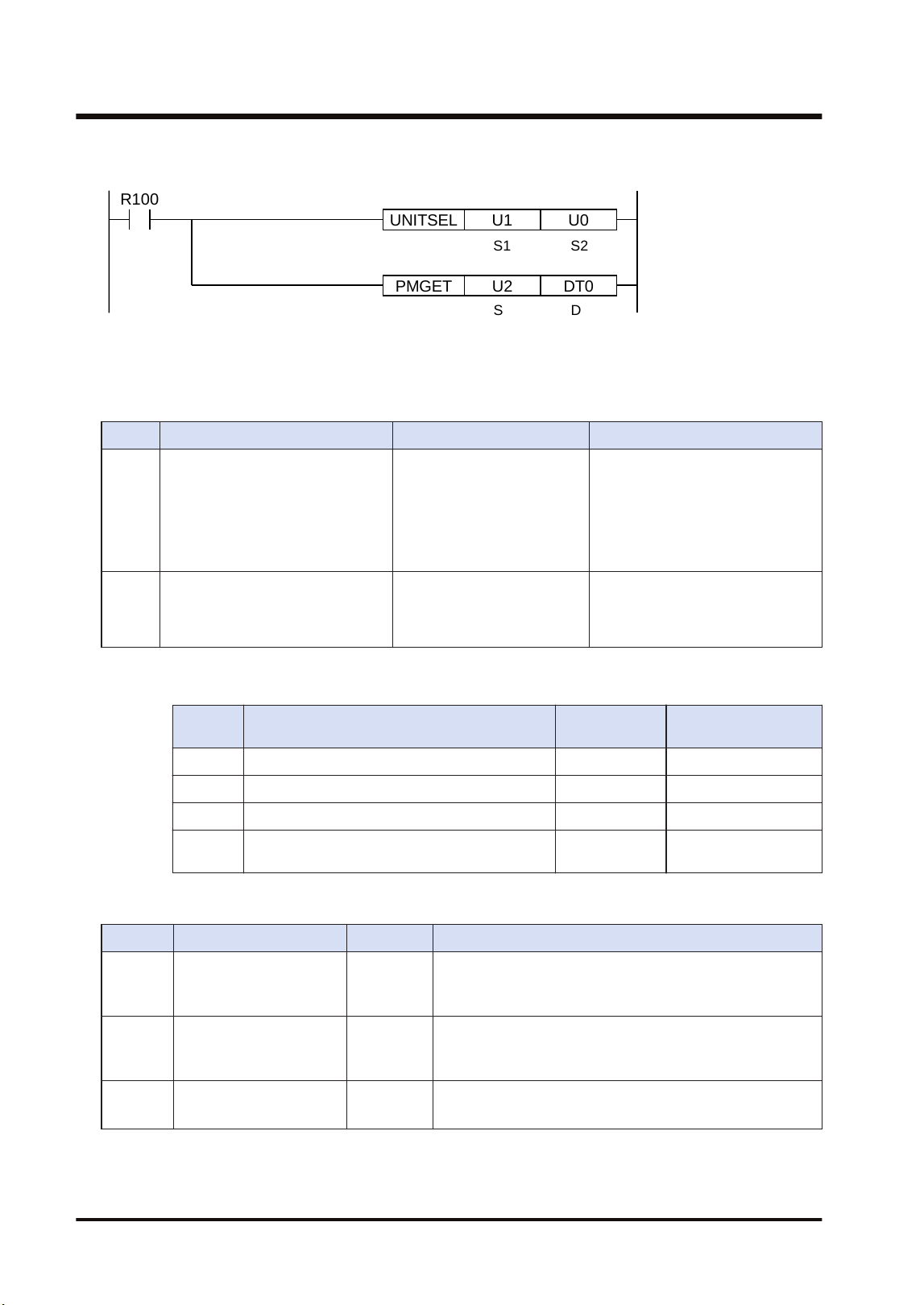
■
Instruction format
PMGET DT0U2
R100
UNITSEL U0U1
S1 S2
S D
(Note 1) The above figure shows the case that the FP7 MW Unit of S1=U1 (slot no.1) is specified by UNITSEL
instruction.
■
Operand
Item Settings Settable device Setting range
S Specify the type of acquired data. WX,WY,WR,WL,DT,LD,U
0: PLC link communication state
1: Network participation state
2: Detail of W link communication
error
3: PLC link refresh operation
monitor
D
Specify the starting address of the
area storing the acquired
communication parameter
(monitor information).
WX,WY,WR,WL,DT,LD
(Note 1)
(Note 1) The size of the area storing data varies in the range of 3 to 15 words according to the data type
specified in [S].
Value of
[S]
Type No. of words Storage location
0 PLC link communication state 3 [D] to [D+2]
1 Network participation state 3 [D] to [D+2]
2 Detail of W link communication error 15 [D] to [D+14]
3 PLC link refresh operation monitoring
information
8 [D] to [D+7]
■
PLC link communication state (When [S] = 0)
Item Range Description
[D]
PLC Link
address duplicate
destination
H0 to HF
bit0 to bit15: Unit no. 1 to unit no. 16
OFF: Normal, ON: Area duplication occurs (The position of
destination unit is set to ON.)
[D+1]
PLC Link
transmission assurance
relay
H0 to HF
bit0 to bit15: Unit no. 1 to unit no. 16
OFF: When stopped or in abnormal state, ON: PLC link
communicating normally
[D+2]
PLC Link
operation mode relay
H0 to HF
bit0 to bit15: Unit no. 1 to unit no. 16
OFF: PROG. mode, ON: RUN mode
9.1 Communication Instructions
9-6 WUME-FP7MW-06

■
Network participation state (When [S] = 1)
Item Range Description
[D]
No. of units added to the
link
U0 to U32
The number of units added to the link is stored. The value
is 0 when the existing unit in the network is only one or a
unit number is being changed.
[D+1]
Link participation unit flag
Unit nos. 1 to 16
H0 to HF
bit0 to bit15: Unit no. 1 to unit no. 16
OFF: Not exist, ON: Participating
[D+2]
Link participation unit flag
Unit nos. 17 to 32
H0 to HF
bit0 to bit15: Unit no. 17 to unit no. 32
OFF: Not exist, ON: Participating
■
[D] Detail of W link communication error (When [S] = 2)
Item Range
[D] No. of occurrences of non-token state U0 to U255
[D+1] No. of occurrences of duplicate tokens U0 to U255
[D+2] No. of occurrences of non-signal state U0 to U255
[D+3] No. of occurrences of synchronous error U0 to U255
[D+4] No. of occurrences of transmission answer NACK U0 to U255
[D+5] No. of occurrences of three consecutive transmission answers NACK U0 to U255
[D+6] No. of occurrences of transmission answer WACK U0 to U255
[D+7] No. of occurrences of three consecutive transmission answers WACK U0 to U255
[D+8] No. of occurrences of non-response U0 to U255
[D+9] No. of occurrences of three consecutive non-response U0 to U255
[D+10] No. of occurrences of receive command code error U0 to U255
[D+11] No. of occurrences of receive data CRC error U0 to U255
[D+12] No. of absences of receive data end code U0 to U255
[D+13] No. of occurrences of receive data format error U0 to U255
[D+14] No. of occurrences of receive data NOT support error U0 to U255
■
PLC link refresh operation monitoring information (When [S] = 3)
Item Range
[D] No. of receptions RING counter U0 to U65535
[D+1] Reception interval Current value (x1ms)
[D+2] Reception interval Minimum value (x1ms)
[D+3] Reception interval Maximum value (x1ms)
[D+4] No. of transmissions RING counter U0 to U65535
[D+5] Transmission interval Current value (x1ms)
[D+6] Transmission interval Minimum value (x1ms)
[D+7] Transmission interval Maximum value (x1ms)
9.1 Communication Instructions
WUME-FP7MW-06 9-7
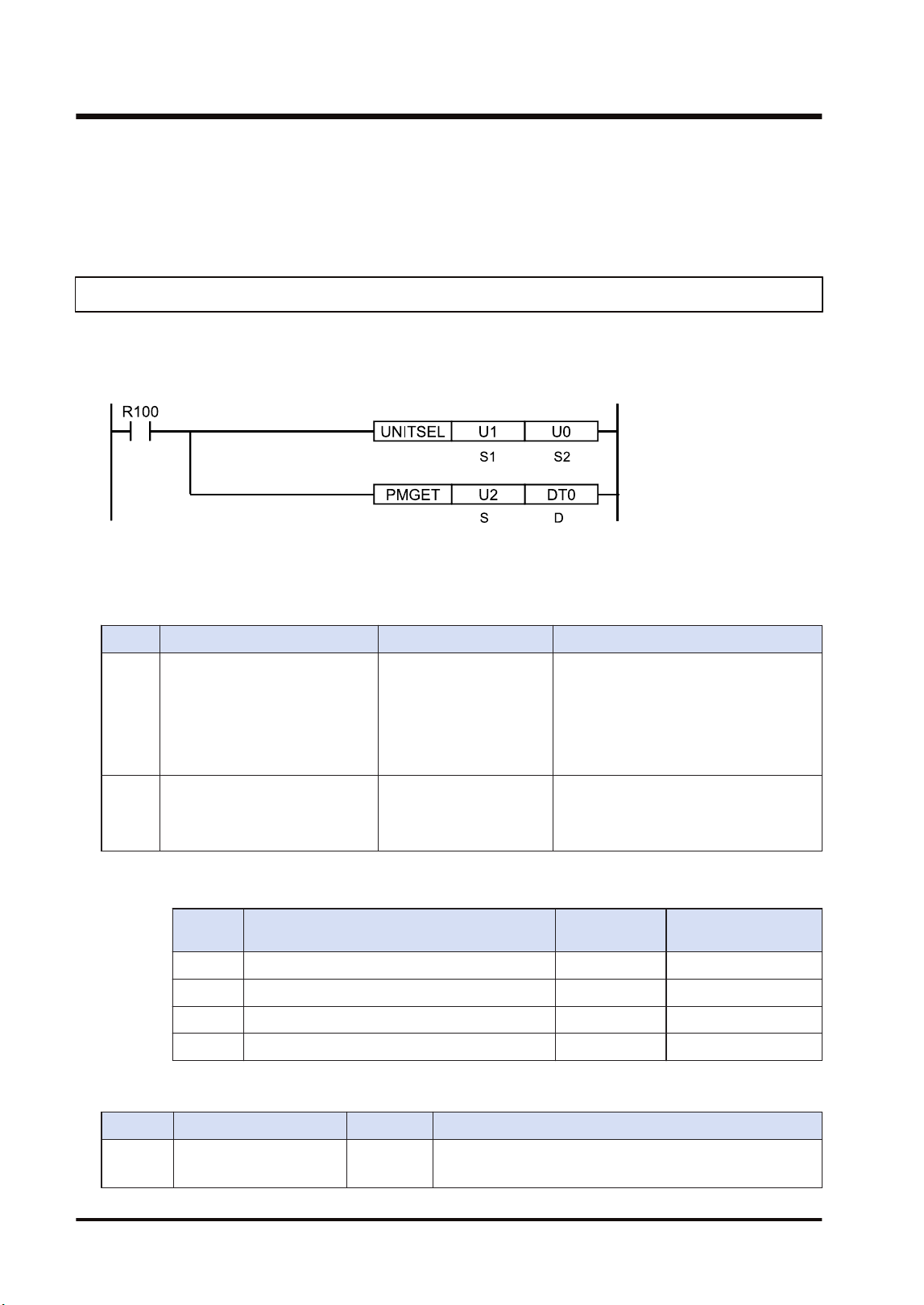
■
Precautions during programming
● Describe UNITSEL instruction immediately before PMGET instruction and specify the slot
number of the unit which acquires parameters in [S1] and 0 in [S2].
9.1.4 PMGET Instruction (For MEWNET-W2)
Monitor information showing the communication state and PLC link operation can be acquired.
■
Instruction format
(Note 1) The above figure shows the case that the FP7 MW Unit of S1=U1 (slot no.1) is specified by UNITSEL
instruction.
■
Operand
Item Settings Settable device Setting range
S
Specify the type of acquired
data.
WX,WY,WR,WL,DT,LD,U
0: PLC link transmission state
1: Network participation state
2: W2 link error system counter type
error area
3: W2 link error system error register
area
D
Specify the starting address of
the area storing the acquired
communication parameter
(monitor information).
WX,WY,WR,WL,DT,LD
(Note 1)
(Note 1) The size of the area storing data varies in the range of 5 to 18 words according to the data type
specified in [S].
Value of
[S]
Type No. of words Storage location
0 PLC link transmission state 6 [D] to [D+5]
1 Network participation state 5 [D] to [D+4]
2 W2 link error system counter type error area 18 [D] to [D+17]
3 W2 link error system error register area U10 [D] to [D+9]
■
PLC link transmission state (When [S] = 0)
Item Range Description
[D] to [D
+1]
PLC link state monitor
flag Unit no. 1 to 32
H00 to HFF
bit0 to bit31: Unit no. 1 to unit no. 32
OFF: Stop, ON: PLC link communicating normally
9.1 Communication Instructions
9-8 WUME-FP7MW-06

Item Range Description
[D+2] to
[D+3]
PLC link operation mode
flag Unit no. 1 to 32
H00 to HFF
bit0 to bit31: Unit no. 1 to unit no. 32
OFF: PROG. mode, ON: RUN mode
[D+4] to
[D+5]
PLC link operation state
flag Unit no. 1 to 32
H00 to HFF
bit0 to bit31: Unit no. 1 to unit no. 32
OFF: No error, ON: Error occurs in PLC transmission is
ensured.
(Note 1) Even when the above (3) has been set by the PLC link operation state flag>"W2 link unit setting"
of the tool software, the data of 6 words is read by PMGET instruction.
■
Network participation state (When [S] = 1)
Item Range Description
[D]
No. of units added to the
link
U0 to U64
The number of units added to the link is stored. The value is
0 when the existing unit in the network is only one or a unit
number is being changed.
[D+1]
Link participation unit
flag
Unit nos. 1 to 16
H0 to HF
bit0 to bit15: Unit no. 1 to unit no. 16
OFF: Not exist, ON: Participating
[D+2]
Link participation unit
flag
Unit nos. 17 to 32
H0 to HF
bit0 to bit15: Unit no. 17 to unit no. 32
OFF: Not exist, ON: Participating
[D+3]
Link participation unit
flag
Unit nos. 33 to 48
H0 to HF
bit0 to bit15: Unit no. 33 to unit no. 48
OFF: Not exist, ON: Participating
[D+4]
Link participation unit
flag
Unit nos. 49 to 64
H0 to HF
bit0 to bit15: Unit no. 49 to unit no. 64
OFF: Not exist, ON: Participating
■
W2 link error system counter type error area (When [S] = 2)
Item Range
[D] No. of missing tokens U0 to U255
[D+1] No. of duplicate tokens U0 to U255
[D+2] No. of occurrences of non-signal state U0 to U255
[D+3] No. of occurrences of synchronous error U0 to U255
[D+4] No. of occurrences of transmission NACK error (When an error occurs) U0 to U255
[D+5] No. of occurrences of transmission NACK error (At the time of third retry) U0 to U255
[D+6] No. of occurrences of transmission WACK error (When an error occurs) U0 to U255
[D+7] NNo. of occurrences of transmission WACK error (When occurred 16 times
continuously)
U0 to U255
[D+8] No. of occurrences of non-response (When an error occurs) U0 to U255
[D+9] No. of occurrences of non-response (At the time of third retry) U0 to U255
[D+10] No. of receptions of undefined commands U0 to U255
[D+11] No. of occurrences of receive parity check error U0 to U255
[D+12] No. of occurrences of END CODE reception error U0 to U255
9.1 Communication Instructions
WUME-FP7MW-06 9-9
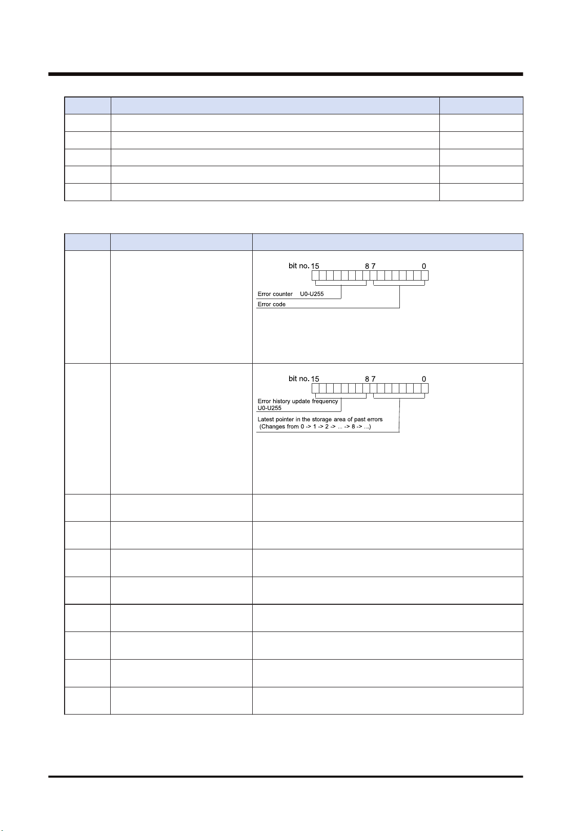
Item Range
[D+13] No. of occurrences of receive data format error U0 to U255
[D+14] No. of occurrences of receive data NOT support error U0 to U255
[D+15] No. of token retransmissions U0 to U255
[D+16] No. of detection of unit OFF U0 to U255
[D+17] No. of occurrences of link disabled state U0 to U255
■
W2 link error system error register area (When [S] = 3)
Item Description
[D] State of error currently occurs
When the same error occurs, the error counter of high byte will
be updated. When the error content changes and the error is
cleared, the information will be stored in the error occurrence
state history area ([D+2] to [D+9]).
[D+1]
Error occurrence state history
management
(Changes from 0 -> 1 -> 2 -> ... -> 8 -> ...)
When the latest pointer in the storage area of past errors is 0, it
indicates that there is no error. When the number of error
updates is 0, it indicates that there is no update.
[D+2]
Error occurrence state history
area 1
History of error occurrence state (parameter of [D]) 1
[D+3]
Error occurrence state history
area 2
History of error occurrence state (parameter of [D]) 2
[D+4]
Error occurrence state history
area 3
History of error occurrence state (parameter of [D]) 3
[D+5]
Error occurrence state history
area 4
History of error occurrence state (parameter of [D]) 4
[D+6]
Error occurrence state history
area 5
History of error occurrence state (parameter of [D]) 5
[D+7]
Error occurrence state history
area 6
History of error occurrence state (parameter of [D]) 6
[D+8]
Error occurrence state history
area 7
History of error occurrence state (parameter of [D]) 7
[D+9]
Error occurrence state history
area 8
History of error occurrence state (parameter of [D]) 8
9.1 Communication Instructions
9-10 WUME-FP7MW-06
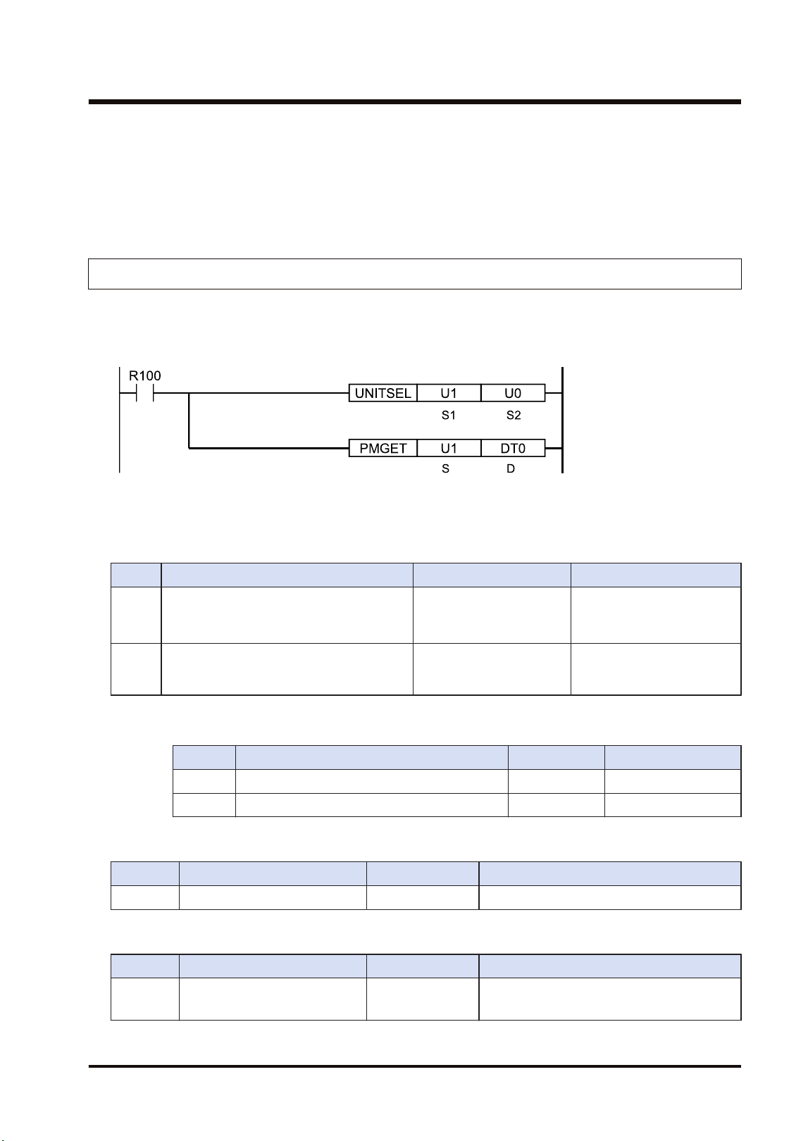
■
Precautions during programming
● Describe the UNITSEL instruction immediately before the PMGET instruction. Specify the
slot number of the unit from which the parameters are acquired for [S1] and specify 0 for
[S2].
9.1.5 PMGET Instruction (For MEWNET-F)
Monitor information showing the communication state can be acquired.
■
Instruction format
(Note 1) The above figure shows the case that the FP7 MW Unit of S1=U1 (slot no.1) is specified by UNITSEL
instruction.
■
Operand
Item Settings Settable device Setting range
S Specify the type of acquired data. WX,WY,WR,WL,DT,LD,U
0: No. of F link services
1: F link operation state
monitor
D
Specify the starting address of the area
storing the acquired communication
parameter (monitor information).
WX,WY,WR,WL,DT,LD
(Note 1)
(Note 1) The size of the area storing data varies in the range of 5 to 18 words according to the data type
specified in [S].
Type No. of words Storage location
0 No. of F link services 1 [D]
1 F link operation state monitor U10 [D] to [D+9]
■
No. of F link services (When [S] = 0)
Item Range Description
[D] F link service counter U0 to U65535 Service ring counter of master unit
■
F link operation state monitor {When [S] = 1)
Item Range Description
[D] to [D
+1]
Connected unit H00 to HFF
bit0 to bit31: Unit no. 1 to unit no. 32
OFF: Disconnected unit, ON: Connected unit
9.1 Communication Instructions
WUME-FP7MW-06 9-11
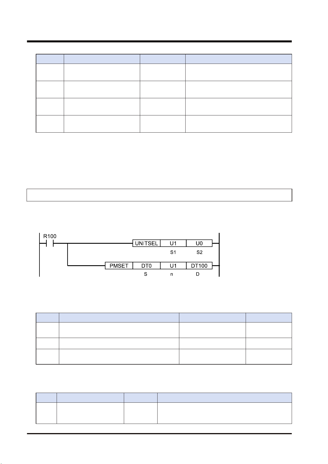
Item Range Description
[D+2] to
[D+3]
Abnormal unit current value H00 to HFF
bit0 to bit31: Unit no. 1 to unit no. 32
OFF: Normal unit, ON: Abnormal unit
[D+4] to
[D+5]
Abnormal unit cumulative value H00 to HFF
bit0 to bit31: Unit no. 1 to unit no. 32
OFF: Normal unit, ON: Abnormal unit
[D+6] to
[D+7]
Setting of slave unit where I/O
verification error occurred
H00 to HFF
bit0 to bit31: Unit no. 1 to unit no. 32
OFF: Normal unit, ON: Abnormal unit
[D+8] to
[D+9]
Slave unit where instantaneous
power failure occurred
H00 to HFF
bit0 to bit31: Unit no. 1 to unit no. 32
OFF: Normal unit, ON: Abnormal unit
■
Precautions during programming
● Describe the UNITSEL instruction immediately before the PMGET instruction. Specify the
slot number of the unit from which the parameters are acquired for [S1] and specify 0 for
[S2].
9.1.6 PMSET/pPMSET Instruction (For MEWNET-W)
Unit numbers and PLC link allocation can be set.
■
Instruction format
(Note 1) The above figure shows the case that the FP7 MW Unit of S1=U1 (slot no.1) is specified by UNITSEL
instruction.
■
Operand
Item Settings Settable device Setting range
S
Specify the starting address of the device storing
set communication parameters.
WX,WY,WR,WL,DT,LD
n Specify the number of set words. WX,WY,WR,WL,DT,LD,U
10 or 1
(Note 1)
D
Specify the device area of the local unit storing the
processing result (1 word).
WX,WY,WR,WL,DT,LD
(Note 1) When the unit number is 17 or more, specify 1.
■
[S] to [S+9]: Communication parameter settings in W mode
Parameter Range Description
[S] Unit no. U1 to U32
It can be changed only when the rotary switch on the front
panel of the unit is set to 0. When using the PLC link, set
it in the range of 1 to 16.
9.1 Communication Instructions
9-12 WUME-FP7MW-06
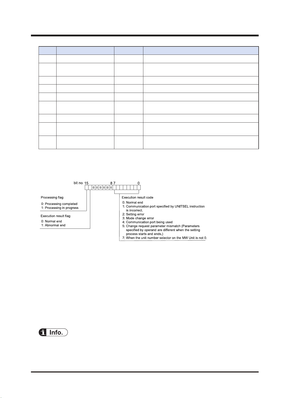
Parameter Range Description
[S+1] Link relay holding start no. U0 to U128 Specify the hold area of link relays by word numbers.
[S+2]
Link register holding start
no.
U0 to U128 Specify the hold area of link relays by word numbers.
[S+3] Memory block number U0 to U7 Memory block no. of PLC link area
[S+4] Range of link relays U0 to U64 Link relay usable range in the above memory block
[S+5] Range of link registers U0 to U128 Link register usable range in the above memory block
[S+6]
Starting number for link
relay transmission
U0 to U63 Link relay transmission start no.
[S+7] Link relay transmission size U0 to U64 Link relay transmission size
[S+8]
Starting number for link
register transmission
U0 - U12 Link register transmission start no.
[S+9]
Link register transmission
size
U1 - U12
As for the link register transmission size, up to 127 words
can be sent.
■
[D]: Processing result
● The execution result is stored in the area of one word.
● The execution result code in the lower byte is valid when the processing flag of bit 15 is zero.
■
Precautions during programming
● The unit number of the FP7 MW Unit can be set by PMSET/pPMSET instruction only when
the unit number selector on the unit is set to 0.
● Describe UNITSEL instruction immediately before PMSET/pPMSET instruction and specify
the slot number of the unit which acquires parameters in [S1] and 0 in [S2].
● Confirm the execution result when the bit 15 (processing flag) in the area specified in [D]
changes from 1 to 0.
● The content set by the PMSET/pPMSET instruction is not held in the case of power outage.
Turn on the power supply again and switch to RUN mode to return to the configuration
information set in the tool software.
● When setting it for the FP7 MW Unit, it cannot be used in an interrupt program.
● For details of sample programs of "PMGET" and "pPMSET" instructions, refer to
"9.1.7 PMSET/pPMSET Instruction (For MEWNET-W2)".
9.1 Communication Instructions
WUME-FP7MW-06 9-13
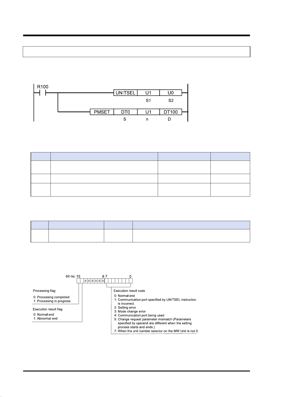
9.1.7 PMSET/pPMSET Instruction (For MEWNET-W2)
Unit numbers can be set.
■
Instruction format
(Note 1) The above figure shows the case that the FP7 MW Unit of S1=U1 (slot no.1) is specified by UNITSEL
instruction.
■
Operand
Item Settings Settable device Setting range
S
Specify the starting address of the device storing set
communication parameters.
WX,WY,WR,WL,DT,LD
n Specify the number of set words. WX,WY,WR,WL,DT,LD,U
U1
(Note 1)
D
Specify the device area of the local unit storing the
processing result (1 word).
WX,WY,WR,WL,DT,LD
(Note 1) For MEWNET-W2, specify 1.
■
[S]: Communication parameter settings in W2 mode
Parameter Range Description
[S] Unit no. U1 to U64
It can be changed only when the rotary switch on the front
panel of the unit is set to 0.
■
[D]: Processing result
● The execution result is stored in the area of one word.
● The execution result code in the lower byte is valid when the processing flag of bit 15 is zero.
■
Precautions during programming
● The unit number of the FP7 MW Unit can be set by PMSET/pPMSET instruction only when
the rotary switch on the unit is set to 0.
9.1 Communication Instructions
9-14 WUME-FP7MW-06
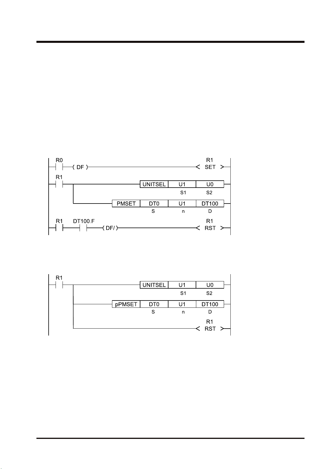
● Describe UNITSEL instruction immediately before PMSET/pPMSET instruction and specify
the slot number of the unit which acquires parameters in [S1] and 0 in [S2].
● Confirm the execution result when the bit 15 (processing flag) in the area specified in [D]
changes from 1 to 0.
● The content set by the PMSET/pPMSET instruction is not held in the case of power outage.
Turn on the power supply again and switch to RUN mode to return to the configuration
information set in the tool software.
● When setting it for the FP7 MW Unit, it cannot be used in an interrupt program.
■
Program example (PMSET)
For the PMSET instruction, it is necessary to turn ON the execution condition of the PMSET
instruction until the end of processing, and turn OFF the execution condition at a scan in which
the end of data transmission is confirmed.
■
Program example (pPMSET)
For pPMSET instruction, when the execution condition arises, the parameter change
processing is performed only once.
9.1 Communication Instructions
WUME-FP7MW-06 9-15
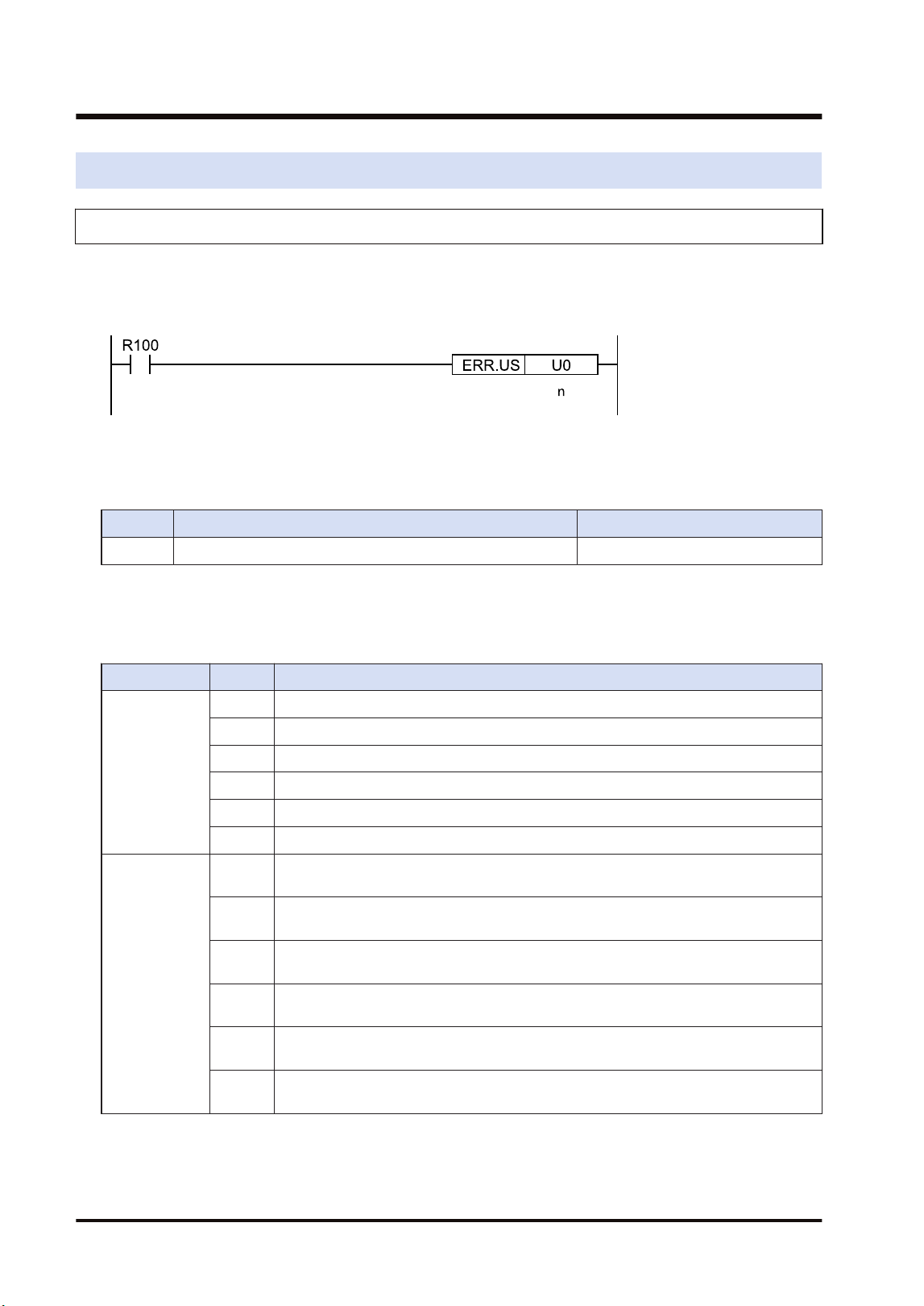
9.2 Special Instructions
9.2.1 ERR Instruction
Errors related to the FP7 MW Unit can be cleared.
■
Instruction format
■
Operand
Item Settings Setting range
n Specify the self-diagnostic error code. 0: Clear the self-diagnostic error.
■
Area cleared by ERR instruction
Resets values of system relays and system data registers as well as clearing errors in the FP7
MW Unit.
Item No. Description
System relay
SR50 FP7 MW Unit 1 error
SR51 FP7 MW Unit 2 error
SR52 FP7 MW Unit 3 error
SR53 FP7 MW Unit 4 error
SR54 FP7 MW Unit 5 error
SR55 FP7 MW Unit 6 error
System data
register
SD90 FP7 MW Unit 1 error (High-order 8 bits = Error code, Low-order 8 bits = Unit
number)
SD91 FP7 MW Unit 2 error (High-order 8 bits = Error code, Low-order 8 bits = Unit
number)
SD92 FP7 MW Unit 3 error (High-order 8 bits = Error code, Low-order 8 bits = Unit
number)
SD93 FP7 MW Unit 4 error (High-order 8 bits = Error code, Low-order 8 bits = Unit
number)
SD94 FP7 MW Unit 5 error (High-order 8 bits = Error code, Low-order 8 bits = Unit
number)
SD95 FP7 MW Unit 6 error (High-order 8 bits = Error code, Low-order 8 bits = Unit
number)
(Note 1) Error information can be read by PMGET instruction.
9.2 Special Instructions
9-16 WUME-FP7MW-06

10 Specifications
10.1 Specifications....................................................................................10-2
10.1.1 General Specifications ................................................................... 10-2
10.1.2 Performance Specifications ........................................................... 10-2
10.2 List of System Relays (SR)...............................................................10-4
10.3 List of System Data Registers (SD) ..................................................10-5
WUME-FP7MW-06 10-1

10.1 Specifications
10.1.1 General Specifications
Item Specifications
Operating ambient
temperature
0°C to 55°C
Storage ambient
temperature
-40°C to +70°C
Operating ambient
humidity
10 to 95% RH (at 25°C with no condensing)
Storage ambient
humidity
10 to 95% RH (at 25°C with no condensing)
Vibration resistance
10 to 55 Hz, 1 cycle/min
(Double amplitude of 0.75 mm, 10 min. on 3 axes)
Shock resistance
98 m/s
2
, 4 times on X, Y and Z directions
Noise resistance
1000 V DC [P-P] with pulse widths of 50 ns or 1 μs (based on in-house
measurements)
Environment Free from corrosive gases and excessive dust. EU Directive applicable standard
Overvoltage category Category II
Pollution degree Pollution degree 2
Weight (main unit) Approx. 100g
Consumption current 100mA or less
10.1.2 Performance Specifications
■
Transmission specifications
Item
Specifications
W mode W2 mode F mode
Communication
method
Token bus Polling
Transmission system Baseband
Baud rate 500k bit/s 500k bit/s、250k bit/s 500k bit/s
Transmission distance
(Total length)
Max. 800 m
Max. 800m (500k bit/s)
Max. 1200m (250k bit/s)
Max. 700 m
No. of connected units Max. 32 units
Master unit: 1 unit + Slave
units: Max. 32 units
Transmission error
check
CRC (Cyclic Redundancy Check) method
Synchronous method Start stop synchronous system
Interface Conforming to RS-485
10.1 Specifications
10-2 WUME-FP7MW-06
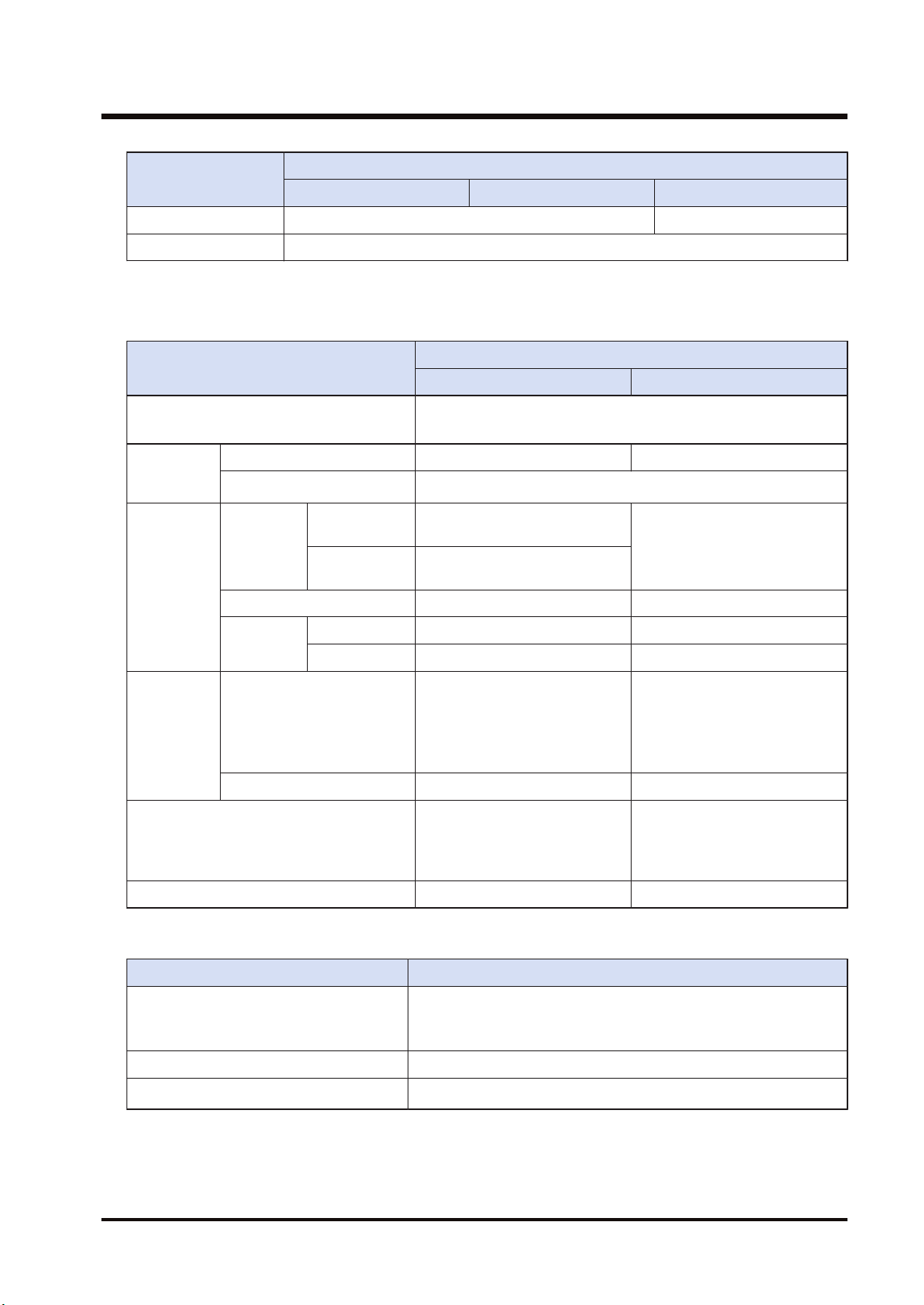
Item
Specifications
W mode W2 mode F mode
Transmission line Twisted pair cable Twisted pair, VCTF
RAS function Hardware self-diagnosis function
(Note 1) For details of the specifications of applicable cables, refer to "3.1.1 Applicable cables".
■
W / W2 mode specifications
Item
Specifications
W mode W2 mode
Communication Functions
PLC link, Data transfer
Remote programming, Computer link, Hierarchy link
Function /
Number of
units
PLC Link Max. 16 units Max. 32 units
Others Max. 32 units
PLC Link
Used area
Link relay
Memory block specification of
WL
WL, WR, LD, DT can be used.
(by setting)
Link register
Memory block specification of
LD
Setting method W link configuration W2 link configuration
Capacity
Link relay Max. 1024 points Max. 4096 points
Link register Max. 128 words Max. 4096 words
Operation
state/Error
annunciation
Used area
● System relay
● System data register
● Detailed information can be
output to WR, LD, DT by
setting.
● System relay
● System data register
● Detailed information can be
output to WL, WR, LD, DT
by setting.
Setting method W link configuration W2 link configuration
Data transfer capacity
Max. 55 words (SEND
instruction)
Max. 56 words (RECV
instruction)
Max. 1020 words
Computer link capacity Max. 118 bytes Max. 2048 bytes
■
F mode specifications
Item Specifications
No. of control points per CPU
Total I/O points: 16064
(excluding 320 points of 10 words occupied by the SCU and ET-
LAN built in the CPU)
No. of control points per unit Total I/O points: 4096
No. of master units per CPU
Max. 4 units
(Note 1)
(Note 1) Up to 4 master units (F mode) can be used in the range of the number of control points of CPU Unit.
10.1 Specifications
WUME-FP7MW-06 10-3
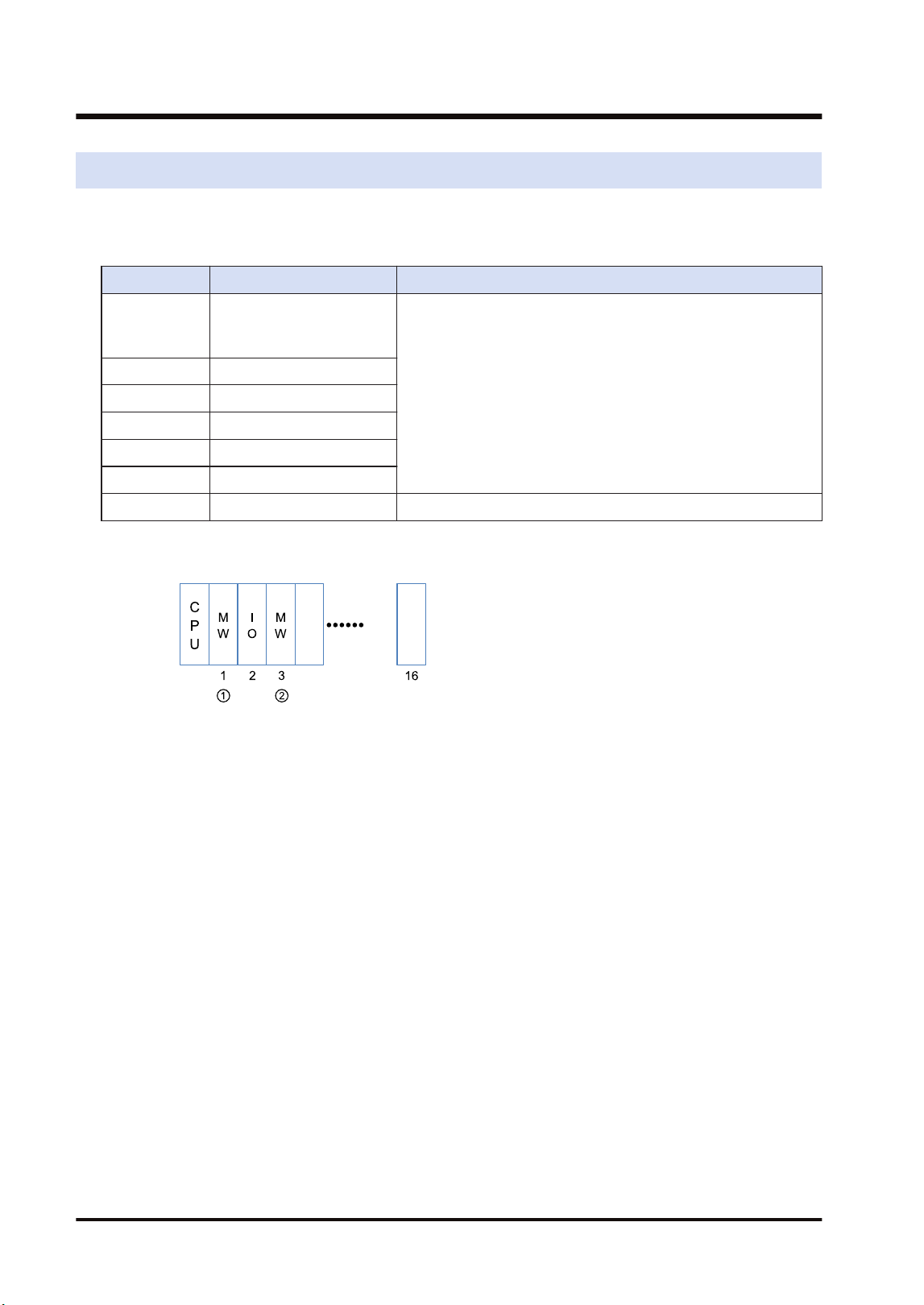
10.2 List of System Relays (SR)
The following is a list of system relays (SR) related to the FP7 MW Unit.
SR50-SR5F
Relay no. Name Description
SR50
FP7 MW Unit error
annunciation relay
(1st unit)
Turns on when an error occurs in the FP7 MW Unit.
The error code and unit number is stored in the system registers
SD90-SD95.
SR51 (2nd unit)
SR52 (3rd unit)
SR53 (4th unit)
SR54 (5th unit)
SR55 (6th unit)
SR56-SR5F Reserved for system
(Note 1) The unit numbers in the above table are those for the installed FP7 MW Units (W mode/W2 mode/F
mode) counted from the unit closest to the CPU unit. They are different from the slot numbers.
10.2 List of System Relays (SR)
10-4 WUME-FP7MW-06
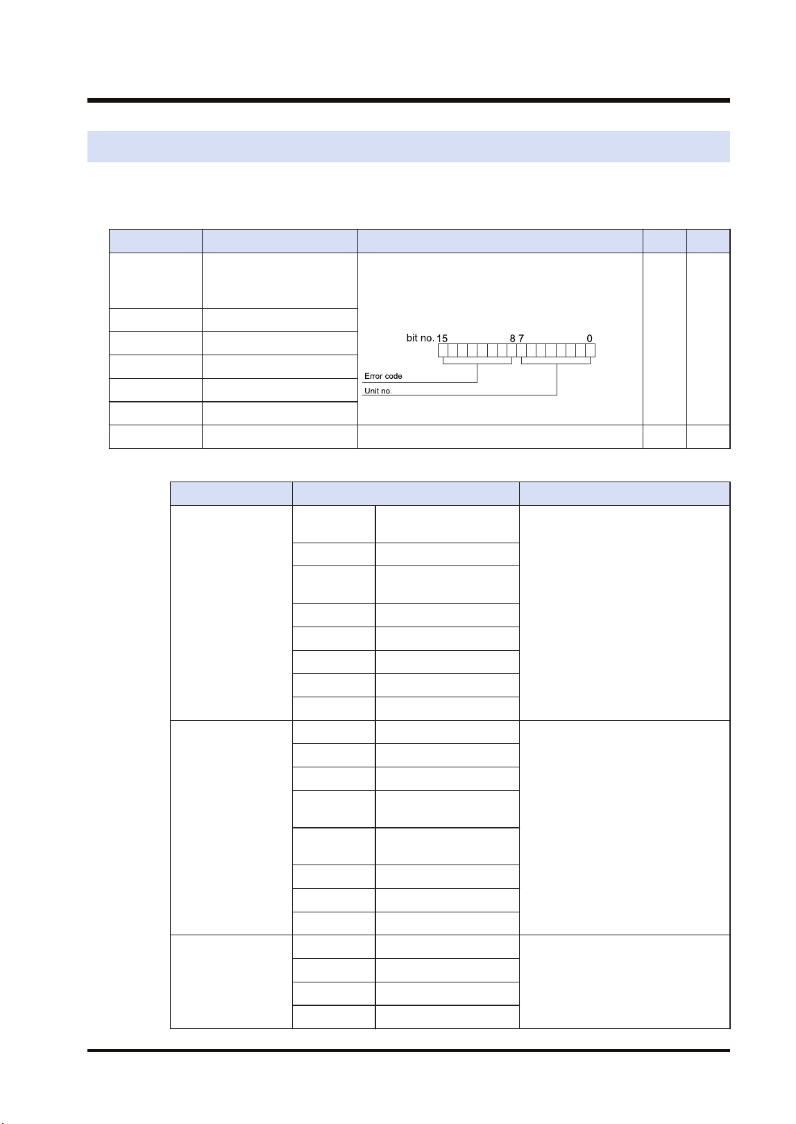
10.3 List of System Data Registers (SD)
The following is a list of system data registers (SD) related to the FP7 MW Unit.
SD90-SD99 (A: Available, Blank: Not available)
Register No. Name Description R W
SD90
FP7 MW Unit error
annunciation register
(1st unit)
When an error occurs in the FP7 MW Unit, the
error code is stored in the high byte and the unit
number is stored in the low byte.
A
SD91 (2nd unit)
SD92 (3rd unit)
SD93 (4th unit)
SD94 (5th unit)
SD95 (6th unit)
SD96-SD99 Reserved for system
(Note 1) The following values are stored in the error code and unit number.
Network Error code Unit No.
MEWNET-W
bit 8 Transmission system
error
H01 to H20 (U1 to U32)
bit 9 Unit number duplicate
bit10 PLC link address
duplicate
bit11 Unit number error
bit12 Undefined
bit13 Undefined
bit14 Undefined
bit15 Undefined
MEWNET-W2
bit 8 Link unit stopped
H01 to H40 (U1 to U64)
bit 9 Link disabled
bit10 Undefined
bit11 Packet transmission
disabled
bit12 PLC link address
duplicate
bit13 Undefined
bit14 Undefined
bit15 Undefined
MEWNET-F
bit 8 Line error
H00 (Fixed)
bit 9 Transmission error
bit10 Prohibited unit
bit11 Terminal unit error
10.3 List of System Data Registers (SD)
WUME-FP7MW-06 10-5

Network Error code Unit No.
bit12 Excessive number of
slots
bit13 Excessive number of I/O
points
bit14 Instantaneous power
failure
bit15 Verification error
10.3 List of System Data Registers (SD)
10-6 WUME-FP7MW-06

11 Appendix
11.1 Compatibility with Conventional Model FP2SH.................................11-2
11.1.1 Restrictions on the Number of Units Installed ................................ 11-2
11.1.2 PLC Link Function (W Mode, W2 Mode)........................................ 11-2
11.1.3 Data Transfer Function (W Mode, W2 Mode) ................................ 11-3
11.1.4 Command Relay Function (W Mode, W2 Mode)............................ 11-4
11.1.5 Remote I/O Function (F Mode)....................................................... 11-5
11.1.6 Serial Communication Unit............................................................. 11-5
11.1.7 No. of Occupied I/O Points............................................................. 11-6
WUME-FP7MW-06 11-1

11.1 Compatibility with Conventional Model FP2SH
11.1.1 Restrictions on the Number of Units Installed
Item FP7 FP2SH
Total number of installed
units
Max. 6 units
Max. 17 units
(Note 1)
W mode Max. 4 units (Of which, PLC link is max.
2 units.)
Max. 5 units (Of which, PLC link is max.
2 units.)
W2 mode Max. 4 units (Of which, PLC link is max.
2 units.)
Max. 8 units (Of which, PLC link is max.
2 units.)
F mode Max. 4 units Max. 4 units
Installation position
In base block (Cannot be installed in
expansion block)
Master backplane is recommended.
(Can be installed on expansion
backplane.)
(Note 1) The total number of installed units of FP2SH shows the total number of the following units; (W mode,
CCU) × 5 units, (W2 mode) × 8 units, and (F mode) × 4 units.
11.1.2 PLC Link Function (W Mode, W2 Mode)
■
Link area
Item FP7 FP2SH
W mode
Capacity
Link relay: 1024 points, Link register:
128 words per unit
Link relay: 1024 points, Link register:
128 words per unit
Allocation
Selectable from the following areas in
the configuraiton.
0: WL0-WL63, LD0-LD127
1: WL64-WL127, LD128-LD255
2: WL128-WL191, LD256-LD383
3: WL192-WL255, LD384-LD511
4: WL256-WL319, LD512-LD639
5: WL320-WL383, LD640-LD767
6: WL384-WL447, LD768-LD895
7: WL448-WL511, LD896-LD1023
Allocated to the fixed areas of WL and
LD.
0: WL0-WL63, LD0-LD127
1: WL64-WL127, LD128-LD255
W2 mode
Capacity
Link relay: 4096 points, Data link: 4096
words per unit
Link relay: 4096 points, Data link: 4096
words per unit
Allocation
Selectable from the following areas in
the configuraiton.
Device: WL/WR/LD/DT
Can also be allocated to local devices.
Can be linked between the DT of FP7
and FL of FP2SH.
Select from the MEWNET-W2 setting
menu, or set by a user program.
Device: WL/WR/LD/DT/FL
(Note 1) When it is used in conjunction with the system using MEWNET-W0, the PLC link area (0: WL0-WL63,
LD0-LD127) and (1: WL64-WL127, LD128-LD255) cannot be allocated redundantly.
11.1 Compatibility with Conventional Model FP2SH
11-2 WUME-FP7MW-06

(Note 2) When the areas of MEWNET-W, MEWNET-W2 and MEWNET-W0 are duplicated in FP7, the self-
diagnostic error (128) which continues the operation occurs.
■
Transmission information monitoring method
Item FP7 FP2SH
Transmission
information
monitoring
method
W mode
● System relays, system data registers
● Copy to registers by the unit
configuration
● Read by PMGET instruction
● Special internal relays, special
registers
W2 mode
● System relays, system data registers
● Copy to registers by the unit
configuration
● Read by PMGET instruction
● Copy to registers by the unit
configuration
● Special internal relays, special
registers
■
MEWNET-W2 Operation of flags related to PLC link
Item FP7 FP2SH
Operation
All-point reception unit also sends the
PLC link status to other units. All-point
transmission unit also perform the
reception processing of other units.
All-point reception unit does not send
the PLC link status. All-point
transmission unit does not perform the
reception processing of other units.
Flag monitored on all-point
transmission unit
Transmission assurance relays of other
FP2W2 (all-point reception unit) turn off.
Transmission assurance relays of other
FP2W2 (all-point reception unit) turn off.
Transmission assurance relays of other
FP7W2 (all-point reception unit) turn on.
Transmission assurance relays of other
FP7W2 (all-point reception unit) turn off.
Flag monitored on all-point
reception unit
Transmission assurance relays of other
FP2W2 (all-point transmission unit) turn
on.
Transmission assurance relays of other
FP2W2 (all-point transmission unit) turn
on.
Transmission assurance relays of other
FP7W2 (all-point transmission unit) turn
on.
Transmission assurance relays of other
FP7W2 (all-point transmission unit) turn
on.
Transmission assurance relays of other
FP2W2 (all-point reception unit) turn off.
Transmission assurance relays of other
FP2W2 (all-point reception unit) turn off.
Transmission assurance relays of other
FP7W2 (all-point reception unit) turn on.
Transmission assurance relays of other
FP7W2 (all-point reception unit) turn off.
(Note 1) When the network is composed of FP7 units only, the status can be confirmed on all the units.
(Note 2) In the case of MEWNET-W, the status can be confirmed on all the units.
11.1.3 Data Transfer Function (W Mode, W2 Mode)
Item FP7 FP2SH
SEND/
RECV
instructio
n
No. of sent
data
Max. 55 words (SEND, Max. 56 words (RECV)
Simultaneous
execution
One instruction per unit can be executed
simultaneously.
Only one instruction can be executed
simultaneously for all mounted units.
Control flag Allocate for each unit. Special Internal Relay
11.1 Compatibility with Conventional Model FP2SH
WUME-FP7MW-06 11-3
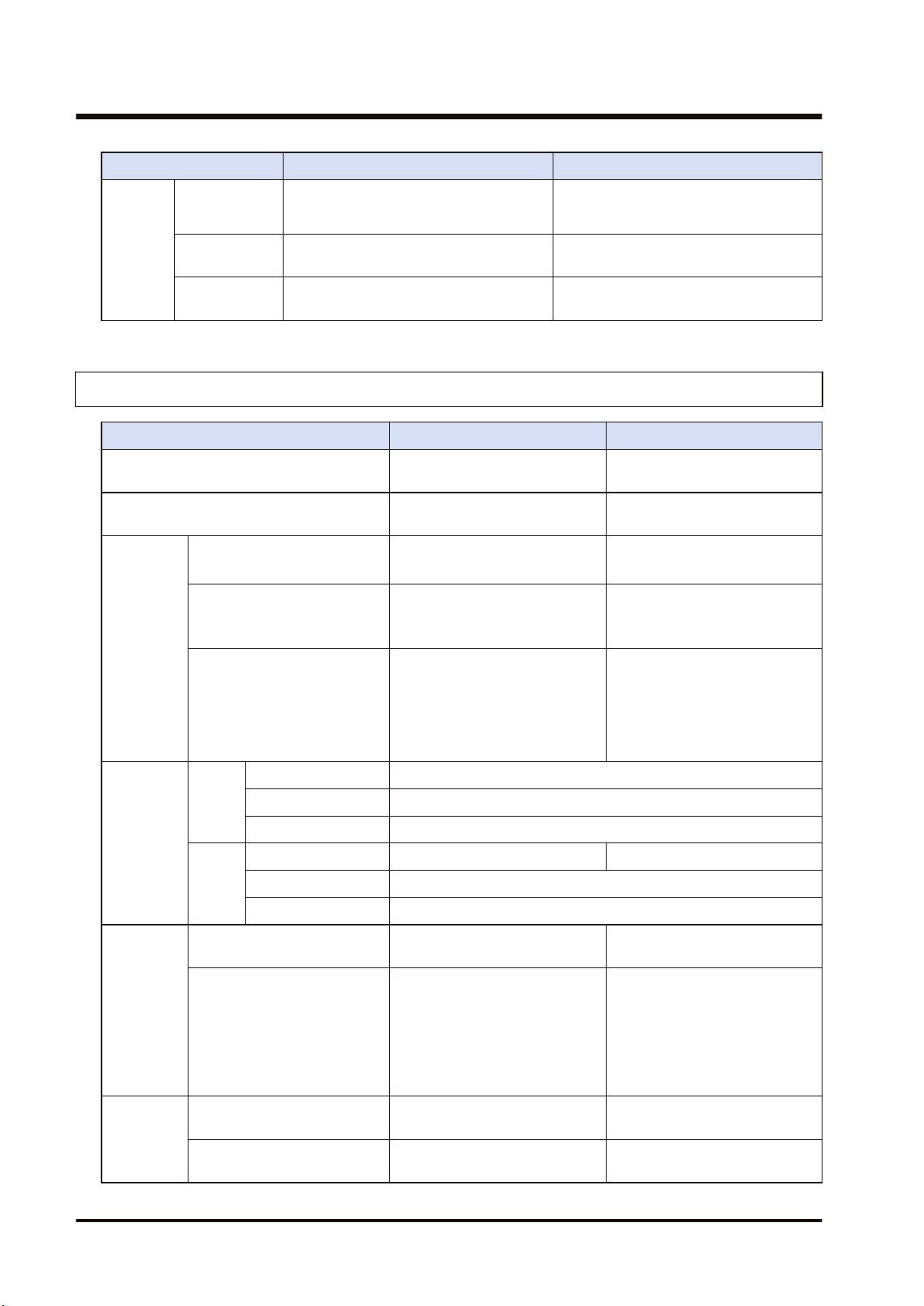
Item FP7 FP2SH
X0: Master communication clear to
send, Y0: Master communication send
active
Execution
result
Specify an arbitrary area by instruction. Special data registers
Hierarchy
transfer
Only the transfer to the same hierarchy
is possible. (1st hierarchy, depth 0 only)
Hierarchy transfer is possible. (Up to
2nd hierarchy, depth 1)
11.1.4 Command Relay Function (W Mode, W2 Mode)
Item FP7 FP2SH
Command input port for remote
programming
USB port / COM0 port Too.l port / COM port
Restriction on relayed units
Impossible to relay to the built-
in ET-LAN.
Possible to relay to the ET-LAN
unit.
Transmissi
on path
setting
function
0C command (Access link
unit)
Specify a slot number.
Settable values: 0x01 to 0x10
Specify a route number.
Settable values: 1 to 15
Relay position information of
LC command
Depth specification
Specify a slot number for the
relay position.
Depth specification: 0 or 1
Specify a route number for the
relay position.
Depth specification: 0 or 1
Transmission path
information in case of power
outage
Transmission path information:
Held in case of power outage.
(Can be continued after the
occurrence of instantaneous
power failure.)
Transmission path information:
Not held in case of power
outage.
(Cannot be continued after the
occurrence of instantaneous
power failure.)
Protocol
and size
capable of
relaying
W
mode
MEWTOCOL7 Not available
MEWTOCOL-COM 118B per frame
MEWTOCOL-DAT 118B per frame
W2
mode
MEWTOCOL7 4kB per frame Not available
MEWTOCOL-COM 2kB per frame
MEWTOCOL-DAT 2kB per frame
Available
transmissio
n path
MEWTOCOL7 (W2 mode)
FP7(FP7)FP7FP7→(FP7)
→FP7
Relay is not available.
MEWTOCOL-COM
MEWTOCOL-DAT
(Note 1)(Note 2)
FP7(FP7)FP7FP7→(FP7)
→FP7
FP7→(FP2)→FP7
FP7→(FP2)→FP2
FP2→(FP2)→FP7
FP2→(FP7)→FP7
FP2→(FP2)→FP2
FP2→(FP2)→FP7
FP2→(FP7)→FP7
Restriction
on relay 1
Relay from W mode to W
mode
Available only when the units in
W mode are two.
Available only when the postion
of reception unit is 1 or 2.
Relay from W mode to W2
mode
Not available
The allowable total number of
W and W2 link units is 2 only.
11.1 Compatibility with Conventional Model FP2SH
11-4 WUME-FP7MW-06

Item FP7 FP2SH
Relay from W2 mode to W
mode
Not available
The allowable total number of
W and W2 link units is 2 only.
Relay from W2 mode to W2
mode
No restriction No restriction
Restriction
on
communica
tion and
relay 2
(Source)
USB port
COM port
SEND/RECV instruction
Communication is not available
when the transmission paths of
commands whose transmission
source is the same type cross
over the MW Unit.
Same as on the left.
(Note 1) Data must be sent by the minimum size limited in the transmission path.
(Note 2) For FP7, the hierarchy transmission for MEWTOCOL-DAT is not available due to the restriction on
SEND/RECV instructions.
11.1.5 Remote I/O Function (F Mode)
Item FP7 FP2SH
I/O allocation method
Master unit base number + No. of I/O
points
(Note 1)
Master unit base number
(Note 2)
Slave unit I/O number
allocation method
The starting numbers for the Input X
and output Y of the same unit number
are the same.
(FP7 I/O allocation method)
Allocate in the order of the input X and
output Y.
(FP2 I/O allocation method)
Slave unit registration
method
Unit configuration System register I/O map registration
Connectable slave unit
FP I/O terminal unit
FP I/O terminal board
FP I/O terminal unit
FP I/O terminal board
FP2 Slave Unit
Transmission information
monitoring method
Read by PMGET instruction
System relays, system data registers
Special internal relays, special data
registers
I/O map mount allocation
For executing the mount registration, it
is necessary to register "F link unit" in
the I/O map in advance.
-
(Note 1) For FP7, the base word number of FP7 WM Unit is a reference.
(Note 2) For FP2SH, the base word number set by the system register (remote I/O allocation) is a reference.
11.1.6 Serial Communication Unit
Item FP7 FP2SH
Remote programming
Remote programming is not available
from Serial Communication Unit
(product no. AFP7NSC).
Remote programming is available (via
MEWNET-W/MEWNET-W2) from CCU
(Computer Communication Unit
(product no. AFP2462)).
11.1 Compatibility with Conventional Model FP2SH
WUME-FP7MW-06 11-5

Item FP7 FP2SH
Remote programming is not available
from MCU (Multi Communication Unit
(product no. AFP2465)).
MEWTOCOL-DAT ASCII
transmission by SEND
instruction
Not available
Sending MEWTCOL-COM commands
by SEND/RECV instruction is available.
MEWTOCOL-DAT ASCII transmission
by SEND instruction is available from
CCU (Computer Communication Unit).
11.1.7 No. of Occupied I/O Points
Item FP7 FP2SH
W mode Input: 1 word / Output: 1 word (Fixed)
16SE(0SE)
W2 mode Input: 1 word / Output: 1 word (Fixed)
F mode Input: 256 word / Output: 256 word
(Max.)
(Note 1) For FP7 (W mode/W2 mode), they are occupied as flags for controlling SEND/RECV instruction.
(Note 2) For FP7 (F mode), the number of occupied points varies according to the number of I/O points
allocated to the remote I/O part.
(Note 3) In the system of FP2SH, they are occupied for one word (16 points). (It can be set to 0 point by the
system register.
11.1 Compatibility with Conventional Model FP2SH
11-6 WUME-FP7MW-06

Record of changes
Manual numbers can be found at the bottom of the manual cover.
Date Manual No. Record of changes
Jun. 2017 WUME-FP7MW-01 1st Edition
May. 2018 WUME-FP7MW-02 2nd Edition
● Errors corrected
Jan. 2019 WUME-FP7MW-03 3rd Edition
● Errors corrected
Sep. 2020 WUME-FP7MW-04 4th Edition
● Errors corrected
Jun. 2022 WUME-FP7MW-05 5th Edition
● Changed manual format
Apr. 2024 WUME-FP7MW-06 6th Edition
● Change in Corporate name
WUME-FP7MW-06

(MEMO)
WUME-FP7MW-06

(MEMO)
WUME-FP7MW-06

Panasonic Industry Co., Ltd.
1006, Oaza Kadoma, Kadoma-shi, Osaka 571-8506, Japan
https://industry.panasonic.com/
Please visit our website for inquiries and about our sales network.
© Panasonic Industry Co., Ltd. 2017-2024
April, 2024
WUME-FP7MW-06
