Loading ...
Loading ...
Loading ...

9
Step6
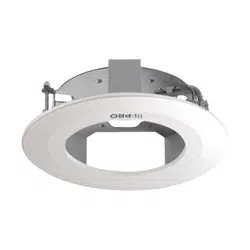
Fix the camera body to the ceiling mount bracket.
The triangle mark of the ceiling mount bracket and the direction marker ( TOP) of the camera body
should be located on the opposite sides.
<When using 4 mounting holes> <When using the adjustment plates>
Fix the camera using 4 fixing screws
(accessory).
Fix the camera on the adjustment plates
(accessory) attached in step 3 using 2 fixing
screws (accessory).
Main body
Main body
Triangle mark
Triangle mark
Camera body
Direction marker
(
TOP)
Fixing screws (accessory)
Recommended tightening torque:
1.6 N·m {1.18 lbf·ft}
Fixing screws (accessory)
Recommended tightening torque:
1.6 N·m {1.18 lbf·ft}
Direction marker
(
TOP)
<When using the attachment plate>
Align the attachment fixing screws on the
bottom side of the camera with the holes
of the attachment plate, and temporarily
attach the camera by rotating it about 15°
clockwise. Next, secure the camera with
the camera fixing screw.
(Recommended tightening torque:
0.78 N·m {0.58 lbf·ft})
Important:
• When using the adjustment plates, do not pass the cables through the hole of the main body.
When the wiring touches the edges of the main body, the cables may get damaged.
Triangle mark
Holes of the
attachment plate
(x4)
Direction marker (
TOP)
Camera fixing screw
Camera body
* Install the camera so that
the wiring should be con-
nected from the side of
the ceiling mount
bracket.
Loading ...
Loading ...
Loading ...