Loading ...
Loading ...
Loading ...

8
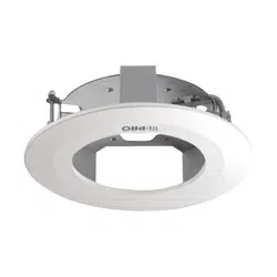
Step3
Fix the plates to the ceiling mount bracket.
Attach the adjustment plates (accessory) or attachment plate (camera accessory) to the ceiling
mount bracket first if they are needed for the attachment of the camera body.
Main body
Triangle mark
Adjustment plates
(accessory)
Fixing screws (accessory)
Recommended tightening torque:
1.6 N·m {1.18 lbf·ft}
Main body
Triangle mark
Attachment plate
(camera accessory)
Fixing screws (accessory)
Recommended
tightening torque:
1.6 N·m {1.18 lbf·ft}
Step4
Fix the ceiling mount bracket onto the ceiling board.
Loosen the fixing screws by rotating them counterclockwise until the length between the clamp
plates becomes wider than the thickness of the ceiling board. Insert the ceiling mount bracket into
the ceiling board, and clamp and secure the ceiling board by rotating the fixing screws clockwise.
Important:
• When the ceiling board is
plasterboard, make sure that
no crack was made on the
ceiling board by clamping.
Step5
Connect the cables to the camera.
Remove the enclosure from the camera body and connect the cables from above the ceiling board
first. Refer to the operating instructions of the camera for information about connection points and
how to make connections.
Triangle mark
Main body
* The "i-PRO" logo on the
camera and the
decorative cover should
be located on the side of
this triangle mark.
Maximum thickness
of the ceiling board is
30 mm
{1-3/16 inches} for
installation.
Fixing screws (accessory)
Recommended tightening torque:
1.6 N·m {1.18 lbf·ft}
Clamp plates
Clamp
the
ceiling
board.
< When securing the camera body
using 2 screws>
< When securing the camera body
using the attachment plate>
Loading ...
Loading ...
Loading ...