Installation, Operating
and Service Instructions
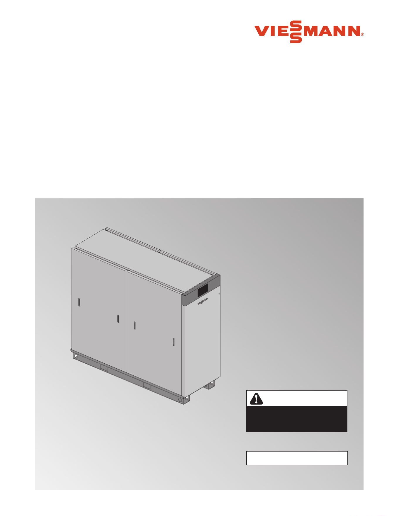
VITOTRANS 300
5833 275 - 07 11/2023
for use by heating contractor
Read and save these instructions
for future reference.
IMPORTANT
Please file in Service Binder
Product may not be exactly as shown
Vitotrans 300, S3HA Series
Indirect Fired Domestic Hot Water Unit – Single Wall
Vitotrans 300, D3HA Series
Indirect Fired Domestic Hot Water Unit – Double Wall
CAUTION
The Vitotrans 300 S3HA and D3HA
series are not suitable for steam
heating applications.

2
5833 275 - 07
Vitotrans 300 Installation, Operating and Service
Safety, Installation and Warranty Requirements
Introduction
Please ensure that these instructions are read and understood before commencing installation. Failure to comply with
the instructions listed below and details printed in this manual can cause product/property damage, severe personal
injury, and/or loss of life. Ensure all requirements below are understood and fulfilled (including detailed information
found in manual subsections).
H Licensed professional heating contractor
The installation, adjustment, service and maintenance
of this equipment must be performed by a licensed
professional heating contractor.
uPlease see section entitled
“Important Regulatory and Installation
Requirements”.
H Product documentation
Read all applicable documentation before commencing
installation. Store documentation near product in a
readily accessible location for reference in the future
by service personnel.
uFor a listing of applicable literature,
please see section entitled “Important
Regulatory and Installation Requirements”.
H Advice to owner
Once the installation work is complete, the heating
contractor must familiarize the system operator/
ultimate owner with all equipment, as well as safety
precautions/requirements, shutdown procedure, and
the need for professional service annually before the
heating season begins.
H Warranty
Information contained in this and
related product documentation must
be read and followed. Failure to do
so renders the warranty null and void.

3
5833 275 - 07
Vitotrans 300 Installation, Operating and Service
Contents
Safety, Installation and Warranty Requirements .............. 2
Licensed professional heating contractor ....................2
Product documentation ............................................2
Advice to owner .....................................................2
Warranty ...............................................................2
Important Regulatory and Installation Requirements ....... 5
Codes ....................................................................5
Mechanical room ....................................................5
Working on the equipment .......................................5
Instructing the system user ......................................6
Initial startup ..........................................................6
Operation ...............................................................6
Technical literature .................................................6
About These Instructions ............................................7
Product Information ....................................................7
Mechanical Room .......................................................7
General Installation Information ....................................8
Connecting to the Heating System - Supply and Return.... 8
Connecting to the Heating System - Closely Spaced Tees .. 9
Connecting to the Heating System - Low Loss Header ..... 9
Connecting to the Heating System - Direct Boiler
Connection .......................................................... 10
Single Direct ......................................................... 11
Single Direct with DHW Storage Tank ....................... 12
Multiple Direct ....................................................... 13
Multiple Direct with DHW Storage Tank ..................... 14
Single Solar Direct with DHW Storage Tank ............... 15
Multiple Solar Direct with DHW Storage Tank ............. 16
Recommended Minimum Service Clearances ................17
Unpacking and Placing the Unit .................................. 18
Preparing the Unit for Installation ........................ 18
Installation Fittings ...................................................19
Waterside Connections .............................................20
Drain Connections ....................................................21
Pressure Relief Valve Connection ...............................21
Electrical Connections ............................................... 22
Initial System Fill ...................................................... 29
Checking Heating Water Connections for Leakage ........29
Commissioning and Initial Start-up ..............................29
User Interface ..........................................................31
Instantaneous ..........................................................32
DHW Storage Tank ...................................................32
DHW Recirculation Pump ........................................ 33
Time schedule .........................................................33
Sanitation Function .................................................36
System Information ............................................... 37
Commissioning ........................................................38
Vitotrans 300 BACnet (IP) Points ...............................41
Domestic Hot Water Production .................................43
Temperature ............................................................44
Instructing the System Operator .................................44
Operating the Service Documents .....................................44
Introduction
Safety
General Information
Installation
Overview
Page

4
5833 275 - 07
Vitotrans 300 Installation, Operating and Service
Contents
Putting the Unit into Operation ...................................45
User Interface ...................................................... 45
Fault Notification ......................................................46
Menu ...................................................................... 46
Settings ..................................................................46
Information ......................................................... 47
Trending ............................................................. 48
Alarms ................................................................. 49
Shutting Down the System ...................................... 49
Troubleshooting ........................................................50
Safety Instructions ...................................................51
Service Equipment ....................................................52
Service and Cleaning ................................................52
Preparing for Service ......................................... 53
Heating System WYE Strainer .................................... 55
Domestic WYE Strainer .............................................55
Heat Exchangers ......................................................56
Descaling Pump .......................................................57
System Pump ..........................................................58
System Faults .......................................................... 60
System Pump Warning Codes ....................................61
System Pump Fault Codes ......................................... 61
Sensors and FHL Location ........................................ 62
Temperature Sensors ............................................. 63
Flow Sensors ........................................................... 63
Fixed High Limit .......................................................64
Completion of Service ............................................... 65
Putting the Unit into Operation After Service ...............67
Faults .....................................................................67
Fault History ...................................................................68
Maintenance Mode / Relay Test ........................................69
Maintenance Mode ..........................................................70
Service ...........................................................................70
Restoring to Normal Operation ..........................................70
Wiring Diagram - S3HA 30, D3HA 30, S3HA 60 and
D3HA 60 ................................................................71
Wiring Diagram - S3HA 90 and D3HA 90 .....................72
Technical Data ........................................................73
Dimensions .....................................................................74
Parts List ................................................................75
Installation Fittings ........................................................... 86
Maintenance ...........................................................87
Maintenance Record .................................................87
Operation
Service
Wiring
Specification
Parts
Maintenance
Page
5
5833 275 - 07
Vitotrans 300 Installation, Operating and Service
WARNING
If the heating system itself is to be filled with Glycol or
any other antifreeze, the system fill must be of non-toxic
or food grade antifreeze. In any circumstance, a non-toxic
fluid must be used. Ensure a copy of the Safety Data
Sheet (SDS) is supplied to the operator/ultimate owner
of the system. The use of Viessmann supplied “Tyfocor-
HTL” solar fill is recommended for the solar heating
circuit.
Codes
The installation of indirect-fired hot water heaters in
boilers and solar system application might be governed
by individual local rules and regulations for this type of
product, which must be observed. Always use latest
editions of codes.
In the Commonwealth of Massachusetts, all plumbing
work must be done by a licensed plumber or gas-fitter
and for gas installations, all gas piping must be done by
a licensed gas-fitter.
Mechanical room
Ensure the mechanical room complies with the
requirements of the system design guideline and/or
Technical Data Manual (available from your Viessmann
sales representative).
The unit must be installed in a mechanical room which
is never subject to freezing temperatures.
Ensure water is drained if not in use and danger of
freezing exists in the mechanical room.
Working on the equipment
The installation, adjustment, service, and maintenance
of this equipment must be done by a licensed professional
heating contractor who is qualified and experienced in
the installation, service, and maintenance of hot water
heating systems. There are no user serviceable parts on
this equipment.
Ensure main power supply to equipment, the heating
system, and all external controls has been deactivated.
Close main oil or gas supply valve. Take precautions to
avoid accidental activation of power during service work.
uPlease carefully read this manual prior to attempting
installation. Any warranty is null and void if these
instructions are not followed.
This product must be installed observing not only the
information and instruction provided in the pertinent
product literature (see list on the following page), but
also all local, provincial/state plumbing and building
codes, as they apply to this product and all periphery
equipment.
For information regarding other Viessmann System
Technology componentry, please reference
documentation of the respective product (available from
your Viessmann sales representative).
We offer frequent installation and service seminars to
familiarize our partners with out products. Please inquire.
uThe completeness and functionality of field supplied
electrical controls and components must be verified
by the heating contractor. These include low-water
cut-offs, flow switches (if used), staging controls,
pumps, motorized valves, air vents, thermostats,
temperature controls, etc.
Safety
Important Regulatory and Installation Requirements
6
5833 275 - 07
Vitotrans 300 Installation, Operating and Service
Safety
Important Regulatory Requirements (continued)
Technical literature
Literature applicable to all aspects of the Vitotrans:
- Technical Data Manual
- Installation, Operating and Service Instructions
- Wiring diagram
uLeave all literature at the installation site and advise the
system operator/ultimate owner where the literature
can be found. Contact Viessmann for additional copies.
Instructing the system user
The installer of the system is responsible to ensure the
system operator/ultimate owner is made familiar with the
system functioning, its activation, and its shut-down.
The operator/ultimate owner should also be instructed to
complete and mail the warranty registration form in order
to be eligible for limited warranty.
Initial startup
Initial start-up must be performed by a qualified heating
contractor. Completion of the Maintenance Record by the
heating contractor is also required.
uThe following topics must be covered:
Proper system operation sequence.
Explain the equipment as well. Demonstrate an
emergency shut-down, what to do and what not.
Explain that there is no substitute for proper maintenance
to help ensure safe operation.
uThe Maintenance Record is located on page 87 of this
manual.
uFailure to abide by all the requirements set out in the
technical literature renders warranty null and void.
Operation
Please carefully read the operating and service section of
this manual prior to operation.
The installer of the system is responsible to ensure the
system operator/ultimate owner is made familiar with the
system functioning, its activation, and its shut-down.
The operator/ultimate owner should also complete and
mail the warranty registration form in order to be eligible
for limited warranty.
CAUTION
For the Vitotrans 300 S3HA series only the heat transfer
medium must be water or other non-toxic fluid having a
toxicity rating or class of 1, as listed in clinical toxicology of
commercial products, 5th edition. The pressure of the heat
transfer medium must be limited to a max. of 30 psig by an
approved safety or relief valve.
7
5833 275 - 07
Vitotrans 300 Installation, Operating and Service
About These Instructions
Product Information
Take note of all symbols and notations intended to draw attention to potential hazards or important product information.
These include “WARNING”, “CAUTION”, and “IMPORTANT”. See below.
uWarnings draw your attention to the presence of
potential hazards or important product information.
uCautions draw your attention to the presence of
potential hazards or important product information.
uHelpful hints for installation, operation or maintenance
which pertain to the product.
uThis symbol indicates that additional, pertinent
information is to be found.
uThis symbol indicates that other instructions must be
referenced.
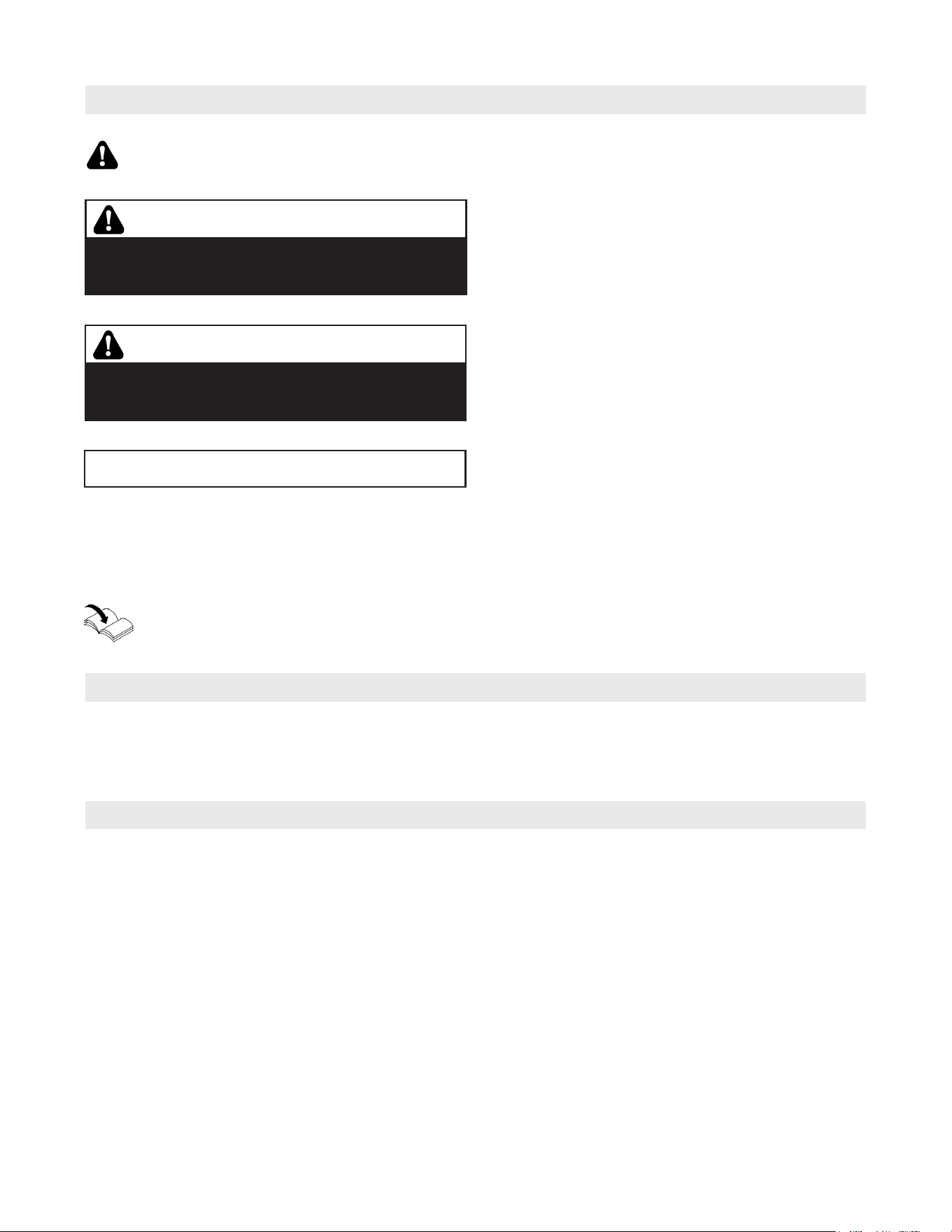
WARNING
Indicates an imminently hazardous situation which, if
not avoided, could result in substantial product/property
damage, serious injury or loss of life.
CAUTION
Indicates an imminently hazardous situation which, if not
avoided, may result in minor injury or product/property
damage.
IMPORTANT
u
General Information
The Vitotrans is a domestic hot water heating system
for direct (instantaneous) hot water heat or use with
a field supplied domestic hot water storage / DHW
storage tanks.
Mechanical Room
The Vitotrans 300 should be located in a heated indoor
space, near a floor drain.
Prevent high levels of humidity.
Prevent freezing and ensure good ventilation.
Otherwise, the system may suffer faults and damage
which is not covered under warranty.
8
5833 275 - 07
Vitotrans 300 Installation, Operating and Service
Installation
General Installation Information
The examples on the following pages depict possible
piping layouts of the Vitotrans 300, equipped with
Viessmann System Technology.
For system combinations, please install only
feasible combinations listed in the Viessmann Price List.
Please note that the following examples are simplified
conceptual drawings only!
Piping and necessary componentry must be field
verified.
Proper installation and functionality in the field is the
responsibility of the heating contractor.
IMPORTANT
Clearances
A minimum of 2 in. (51 mm) circumferential clearance
from non-insulated hot water pipes to combustible
construction must be maintained. In cases where the
pipes are insulated with pipe insulation of sufficient
thickness and insulation values, the above clearance
may be reduced to 0 in. (refer to local codes).
Note: In the following piping layout examples all pumps
are field supplied.
WARNING
If a DHW storage tank is used, the installer must verify
proper operation of the tank temperature sensor with
the original manufacturer of the tank.
Viessmann strongly recommends the installation of a
thermostatic tempering valve in the DHW supply line.
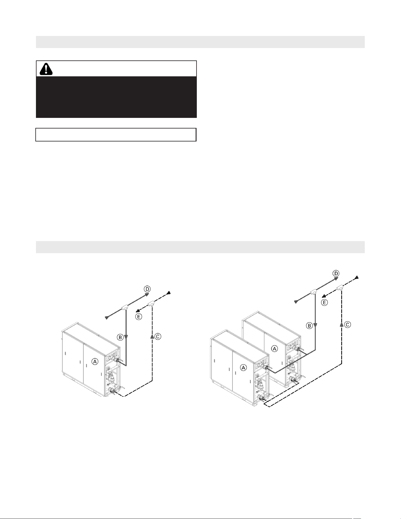
Connecting to the Heating System - Supply and Return
Legend
A Vitotrans 300
B Vitotrans supply
C Vitotrans return
D Heating system supply
E Heating system return
Branch off from main heating
system supply and return.
The system heat source (boiler) should be set to supply
water to the Vitotrans 300 at least 20ºF (11ºC) higher
than the desired DHW setpoint. It is recommended that
the Vitotrans 300 is connected close to the heat source.
Install isolation valves in all heating, domestic piping
and recirculation piping as necessary to service all
equipment properly (e.g. pumps).
The schematics on the following pages are to be used
as guidelines only. They do not display all system
varieties, safety devices, or concepts possible. Specific
system layouts may be further discussed with the local
Viessmann sales representative office.
9
5833 275 - 07
Vitotrans 300 Installation, Operating and Service
Installation
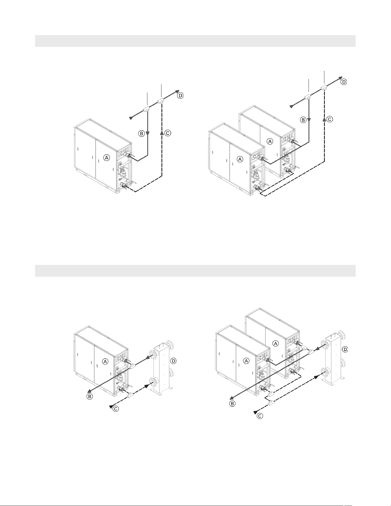
Connecting to the Heating System - Closely Spaced Tees
Connecting to the Heating System - Low Loss Header
Legend
A Vitotrans 300
B Vitotrans supply
C Vitotrans return
D Heating system supply
Legend
A Vitotrans 300
B Vitotrans supply
C Vitotrans return
D Connection to heating equipment
* Maximum spacing between tees is 4X the pipe diameter.
Branch off from main heating system supply and
return from the system side of the low loss header.
Branch off from main heating
system supply.
The system heat source (boiler) should be set to supply
water to the Vitotrans 300 at least 20ºF (11ºC) higher
than the desired DHW setpoint. It is recommended that
the Vitotrans 300 is connected close to the heat source.
The system heat source (boiler) should be set to supply
water to the Vitotrans 300 at least 20ºF (11ºC) higher
than the desired DHW setpoint. It is recommended that
the Vitotrans 300 is connected close to the heat source.
*
*
10
5833 275 - 07
Vitotrans 300 Installation, Operating and Service
Installation
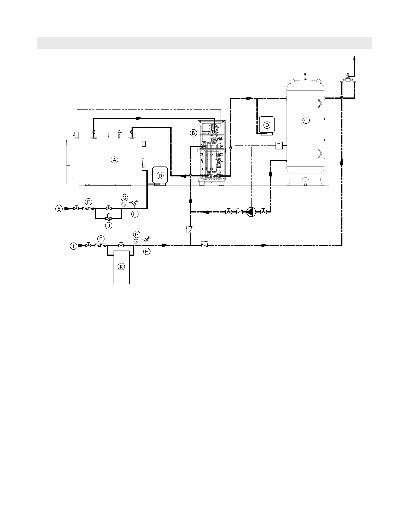
Connecting to the Heating System – Direct Boiler Connection
Legend
A High Mass Boiler (example: CM2)
B Vitotrans 300
C DHW Storage Tank
D Expansion tank
E System Fill
F Back Flow Preventor
G Pressure Guage
H Safety Relief Valve
I Domestic Cold Water (DCW)
J Pressure Reducing Valve
K Water Softener
The Vitotrans 300 may be connected directly to a hot
water heating boiler when following the system design
considerations below;
- DHW load type (constant load with minimal
fluctuations) – Vitotrans directly connected to the
hot water heating boiler operates optimally with
steady DHW flow or gradual fluctuations to DHW flow
- Thermal mass/water content of the hot water heating
boiler - High mass boilers are typically better suited
for direct connection to the Vitotrans
- Modulation range of the hot water heating boiler
– the boiler should be sized and selected based on
matching the anticipated minimum and maximum
DHW load
- Use with or without a DHW Storage Tank, a DHW
storage tank will absorb small fluctuations in DHW
temperature generated by rapid changes in DHW load
Taking into consideration the points above, the system
designer will be able to optimize the system to ensure
system performance, occupant comfort and longevity of
the system.
The system heat source (boiler) should be set to supply
water to the Vitotrans 300 at least 20ºF (11ºC) higher
than the desired DHW setpoint. It is recommended that
the Vitotrans 300 is connected close to the heat source.
11
5833 275 - 07
Vitotrans 300 Installation, Operating and Service
Installation
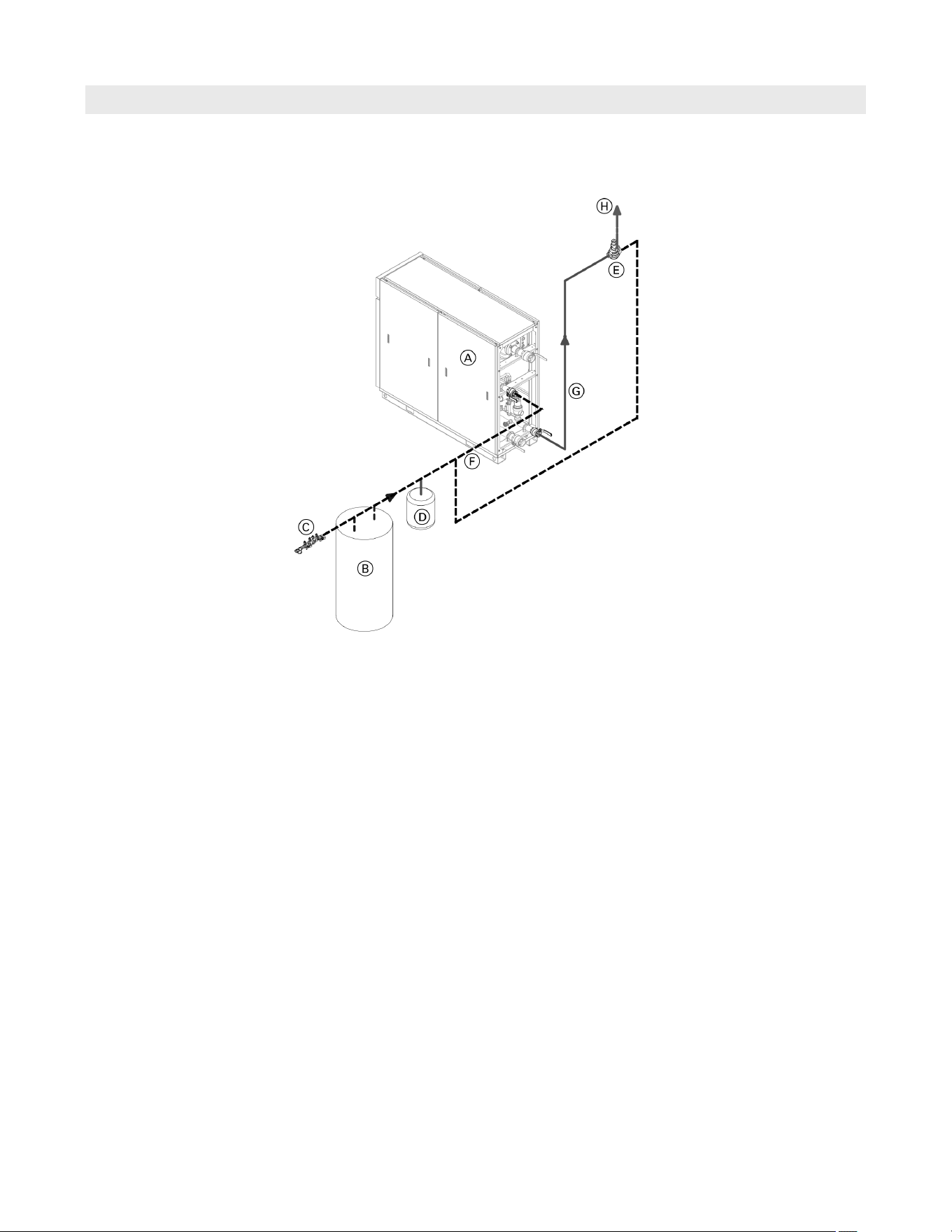
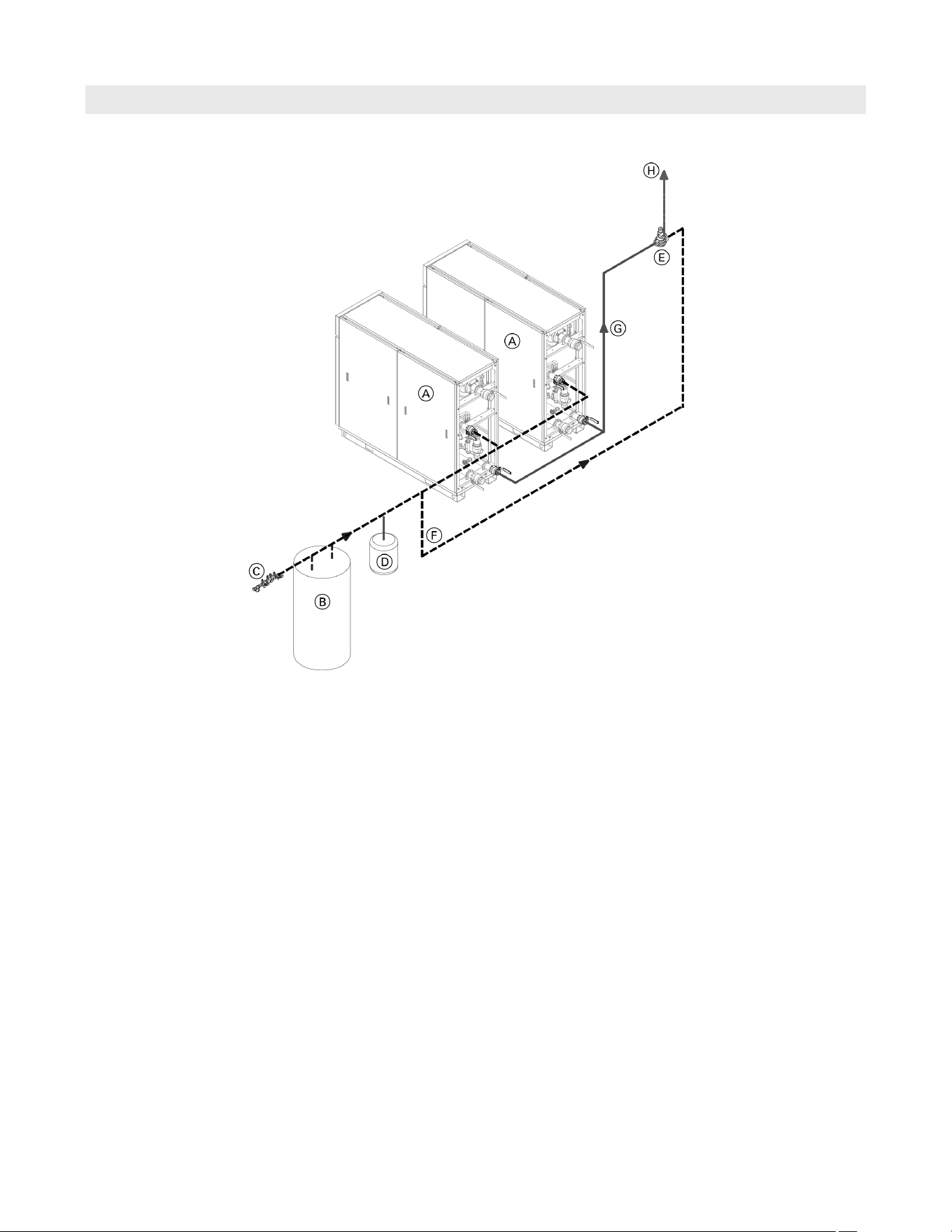
Single Direct
Vitotrans 300 with ....
direct connection to building DHW system.
Legend
A Vitotrans 300
B Water softening equipment
C Back flow preventer
D Expansion tank
E Point of source tempering valve
F Domestic cold water (DCW)
G Domestic hot water (DHW)
H Tempered water building supply
Single Vitotrans 300, for use with direct / instantaneous
domestic hot water heating. For use with long steady
draws of DHW.
Minimum DHW flow activation adjust between 5 and 30 GPM
(19 and 114 L/min). This is a user adjustable setting that can
be set based on the DHW system operating characteristics.
12
5833 275 - 07
Vitotrans 300 Installation, Operating and Service
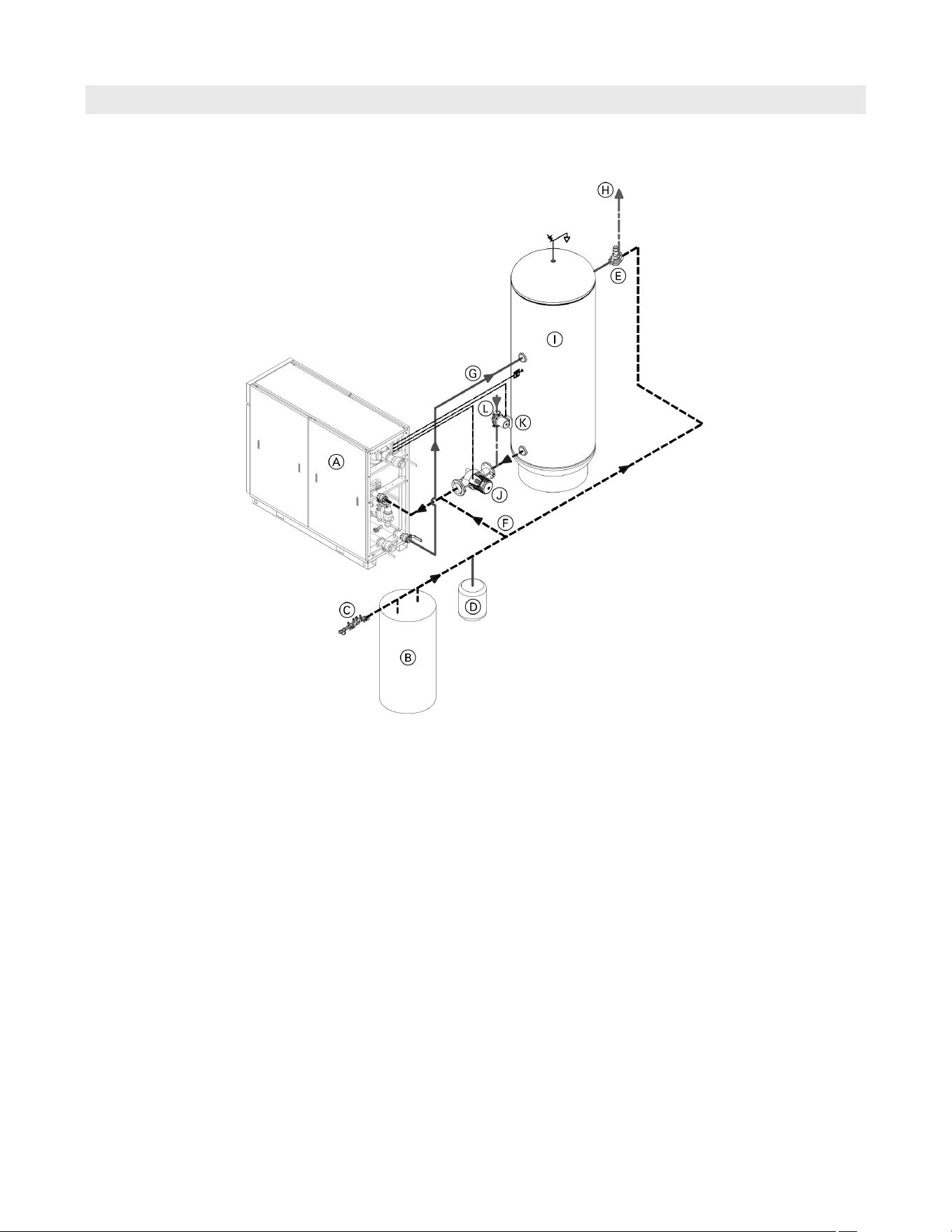
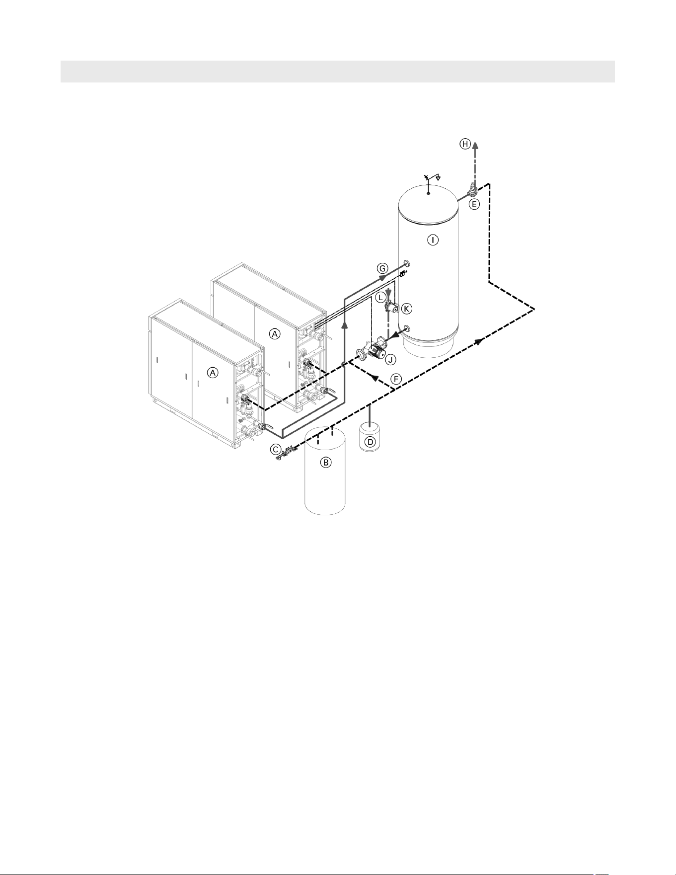
Single Direct with DHW Storage Tank
Installation
Single Vitotrans 300, for use with DHW storage tank, for
stored domestic hot water with integration to the building
recirculation pump and tank loading pump.
Note: A DHW storage tank is highly recommended for
applications where fluctuating DHW system flow
rates, particularly those flow rates below 30 GPM
(114 L/min) for all Vitotrans 300 models sizes.
The DHW storage tank loading pump should be sized
according to DHW storage tank’s size and desired
recovery time, but must not exceed the maximum flow
for the associated Vitotrans 300 model size. It is
recommended that the DHW storage tank loading pump
should provide at least 30 GPM (114 L/m) of flow and be
able to overcome the head losses of the Vitotrans 300
and the piping connecting it to the DHW storage tank.
The minimum flow activation setting for the Vitotrans
300 can be set between 5 and 30 GPM (19 and 114 L/m)
when used with a DHW storage tank. When determining
the activation setpoint, consider the size of the DHW
storage tank and the anticipated minimum constant DHW
draw rate (based on usage patterns). It is also important
to identify the minimum output of the heating system and
use this as a factor when choosing a sufficient activation
setting. This will help reduce short cycling of the heating
equipment.
Note: It is the responsibility of the system designer
to ensure the sizing of the tank loading pump
and corresponding DHW storage tank are sized
for the required demand.
Legend
A Vitotrans 300
B Water softening equipment
C Back flow preventer
Note: for the type of backflow preventor consult
the local plumbing code requirements.
D Expansion tank - domestic water
E Point of source domestic water tempering valve
F Domestic cold water (DCW)
G Domestic hot water (DHW)
H Tempered DHW building supply
I DHW DHW storage tank
J DHW storage tank circulation pump
K DHW recirculation pump
L DHW recirculation line from building
Vitotrans 300 with ....
DHW DHW storage tank, for system applications
where low or fluctuating DHW flow rates may occur,
to prevent short-cycling of the system and to provide
added comfort through DHW recirculation.
13
5833 275 - 07
Vitotrans 300 Installation, Operating and Service
Multiple Direct
Installation
Legend
A Vitotrans 300
B Water softening equipment
C Back flow preventer
D Expansion tank
E Point of source tempering valve
F Domestic cold water (DCW)
G Domestic hot water (DHW)
H Tempered water building supply
Multiple Vitotrans 300 with ....
direct connection to building DHW system.
Multiple Vitotrans 300, for use with direct / instantaneous
domestic hot water heating. For use with long steady
draws of DHW.
Minimum DHW flow activation adjust between 5 and 30 GPM
(19 and 114 L/min). This is a user adjustable setting that can
be set based on the DHW system operating characteristics.
14
5833 275 - 07
Vitotrans 300 Installation, Operating and Service
Multiple Direct with DHW Storage Tank
Installation
Multiple Vitotrans 300, for use with DHW storage tank,
for stored domestic hot water with integration to building
recirculation pump and tank loading pump.
Note: A DHW storage tank is highly recommended for
applications where fluctuating DHW system flow
rates, particularly those flow rates below 30 GPM
(114 L/min) for all Vitotrans 300 models sizes.
The DHW storage tank loading pump should be sized
according to DHW storage tank’s size and desired
recovery time, but must not exceed the maximum flow
for the associated Vitotrans 300 model size. It is
recommended that the DHW storage tank loading pump
should provide at least 30 GPM (114 L/m) of flow and be
able to overcome the head losses of the Vitotrans 300
and the piping connecting it to the DHW storage tank.
The minimum flow activation setting for the Vitotrans
300 can be set between 5 and 30 GPM (19 and 114 L/m)
when used with a DHW storage tank. When determining
the activation setpoint, consider the size of the DHW
storage tank and the anticipated minimum constant DHW
draw rate (based on usage patterns). It is also important
to identify the minimum output of the heating system and
use this as a factor when choosing a sufficient activation
setting. This will help reduce short cycling of the heating
equipment.
Note: It is the responsibility of the system designer
to ensure the sizing of the tank loading pump
and corresponding DHW storage tank are sized
for the required demand.
Legend
A Vitotrans 300
B Water softening equipment
C Back flow preventer
Note: for the type of backflow preventor consult
the local plumbing code requirements.
D Expansion tank - domestic water
E Point of source domestic water tempering valve
F Domestic cold water (DCW)
G Domestic hot water (DHW)
H Tempered DHW building supply
I DHW DHW storage tank
J DHW storage tank circulation pump
K DHW recirculation pump
L DHW recirculation line from building
Multiple Vitotrans 300 with ....
DHW storage tank, for system applications where low
or fluctuating DHW flow rates may occur, to prevent
short-cycling of the system and to provide added
comfort through DHW recirculation.
15
5833 275 - 07
Vitotrans 300 Installation, Operating and Service
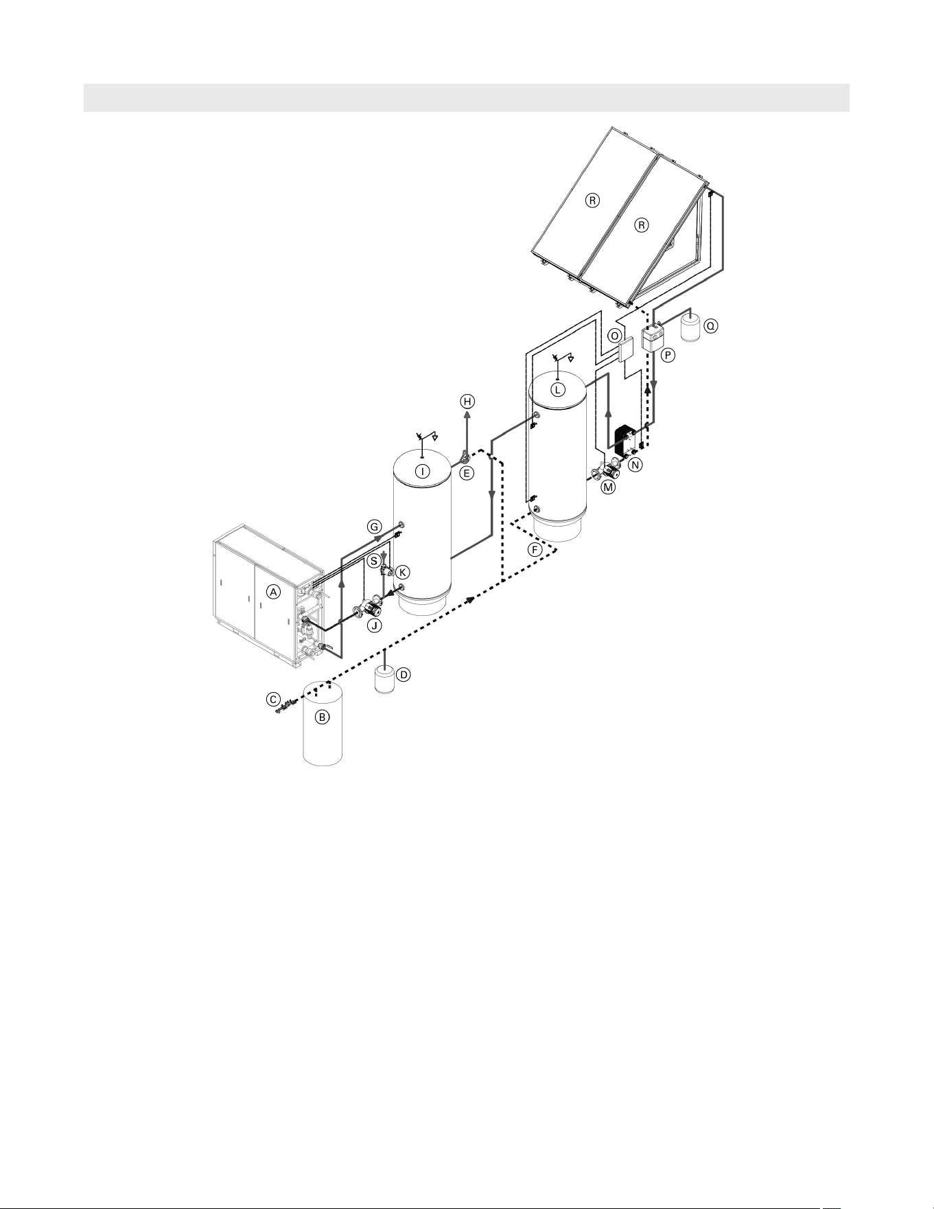
Single Solar Direct with DHW Storage Tank
Installation
Single Vitotrans 300, with DHW storage tank and
integrated solar DHW preheat. The integrated solar
includes using a solar divicon with an external heat
exchanger and solar DHW storage tank with a circulation
pump.
Note: A DHW storage tank is highly recommended for
applications where fluctuating DHW system flow
rates, particularly those flow rates below 30 GPM
(114 L/min) for all Vitotrans 300 models sizes.
The DHW storage tank loading pump should be sized
according to DHW storage tank’s size and desired
recovery time, but must not exceed the maximum
flow for the associated Vitotrans 300 model size. It is
recommended that the DHW storage tank loading pump
should provide at least 30 GPM (114 L/m) of flow and be
able to overcome the head losses of the Vitotrans 300
and the piping connecting it to the DHW storage tank.
The minimum flow activation setting for the Vitotrans
300 can be set between 5 and 30 GPM (19 and 114 L/m)
when used with a DHW storage tank. When determining
the activation setpoint, consider the size of the DHW
storage tank and the anticipated minimum constant DHW
draw rate (based on usage patterns). It is also important
to identify the minimum output of the heating system and
use this as a factor when choosing a sufficient activation
setting. This will help reduce short cycling of the heating
equipment.
Note: It is the responsibility of the system designer
to ensure the sizing of the tank loading pump
and corresponding DHW storage tank are sized
for the required demand.
Legend
A Vitotrans 300
B Water softening equipment
C Back flow preventer
Note: for the type of backflow preventor consult
the local plumbing code requirements.
D Expansion tank - domestic water
E Point of source domestic water tempering valve
F Domestic cold water (DCW)
G Domestic hot water (DHW)
H Tempered DHW building supply
I DHW storage tank
J DHW storage tank circulation pump
K DHW recirculation pump
L Solar DHW storage tank
M Solar tank loading pump
N Heat exchanger
O Solar control unit
P Solar Divicon
Q Solar expansion tank
R Solar panels
S DHW recirculation line from building
Vitotrans 300 with ....
DHW storage tank, for system applications where low
or fluctuating DHW flow rates may occur, to prevent
short-cycling of the system and to provide added
comfort through DHW recirculation.
Solar system for DHW preheat with solar DHW storage
tank.
16
5833 275 - 07
Vitotrans 300 Installation, Operating and Service
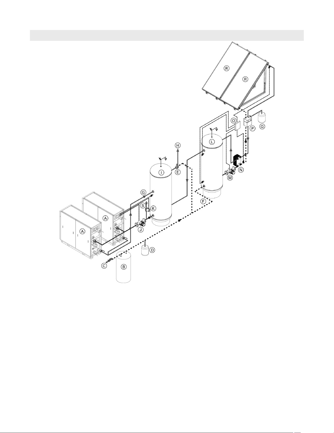
Multiple Solar Direct with DHW Storage Tank
Installation
Single Vitotrans 300, with DHW storage tank and
integrated solar DHW preheat. The integrated solar includes
using a solar divicon with an external heat exchanger and
solar DHW storage tank with a circulation pump.
Note: A DHW storage tank is highly recommended for
applications where fluctuating DHW system flow
rates, particularly those flow rates below 30 GPM
(114 L/min) for all Vitotrans 300 models sizes.
The DHW storage tank loading pump should be sized
according to DHW storage tank’s size and desired
recovery time, but must not exceed the maximum
flow for the associated Vitotrans 300 model size. It is
recommended that the DHW storage tank loading pump
should provide at least 30 GPM (114 L/m) of flow and be
able to overcome the head losses of the Vitotrans 300
and the piping connecting it to the DHW storage tank.
The minimum flow activation setting for the Vitotrans
300 can be set between 5 and 30 GPM (19 and 114 L/m)
when used with a DHW storage tank. When determining
the activation setpoint, consider the size of the DHW
storage tank and the anticipated minimum constant DHW
draw rate (based on usage patterns). It is also important
to identify the minimum output of the heating system and
use this as a factor when choosing a sufficient activation
setting. This will help reduce short cycling of the heating
equipment.
Note: It is the responsibility of the system designer
to ensure the sizing of the tank loading pump
and corresponding DHW storage tank are sized
for the required demand.
Legend
A Vitotrans 300 CA
B Water softening equipment
C Back flow preventer
D Expansion tank
E Point of source tempering valve
F Domestic cold water (DCW)
G Domestic hot water (DHW)
H Tempered water building supply
I DHW storage tank
J DHW storage tank circulation pump
K Building recirculation pump
L Solar DHW storage tank
M Solar tank loading pump
N Heat exchanger
O Solar control unit
P Solar Divicon
Q Solar expansion tank
R Solar panels
S DHW recirculation line from building
Multiple Vitotrans 300 with ....
DHW storage tank, for system applications where low
or fluctuating DHW flow rates may occur, to prevent
short-cycling of the system and to provide added
comfort through DHW recirculation.
Solar system for DHW preheat with solar DHW storage
tank.
17
5833 275 - 07
Vitotrans 300 Installation, Operating and Service
Installation
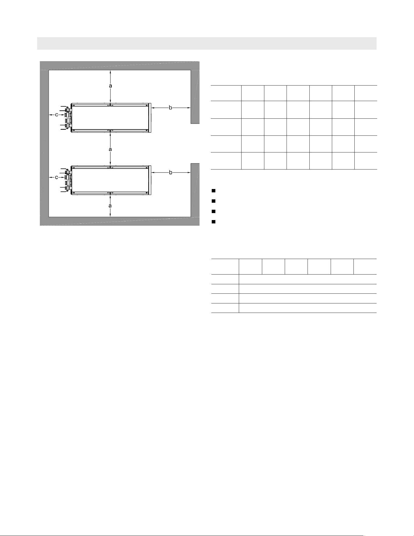
Recommended Minimum Service Clearances
To enable convenient installation and maintenance,
observe the stated clearance dimensions. Maintain the
minimum clearances where space is tight.
Minimum clearances to combustibles
Models
S3HA
30
D3HA
30
S3HA
60
D3HA
60
S3HA
90
D3HA
90
Top 0
Sides 0
Front 0
Floor combustible
Models
S3HA
30
D3HA
30
S3HA
60
D3HA
60
S3HA
90
D3HA
90
a
in.
(mm)
24
(610)
24
(610)
24
(610)
24
(610)
24
(610)
24
(610)
b in.
(mm)
24
(610)
24
(610)
24
(610)
24
(610)
24
(610)
24
(610)
c in.
(mm)
24
(610)
24
(610)
24
(610)
24
(610)
24
(610)
24
(610)
Top in.
(mm)
12
(300)
12
(300)
12
(300)
12
(300)
12
(300)
12
(300)
Mechanical room
Install on a level surface
Avoid high levels of humidity
Protect against frost
Ensure good ventilation
Note: The system may suffer faults and/or damage if the
above are not followed.
18
5833 275 - 07
Vitotrans 300 Installation, Operating and Service
Installation
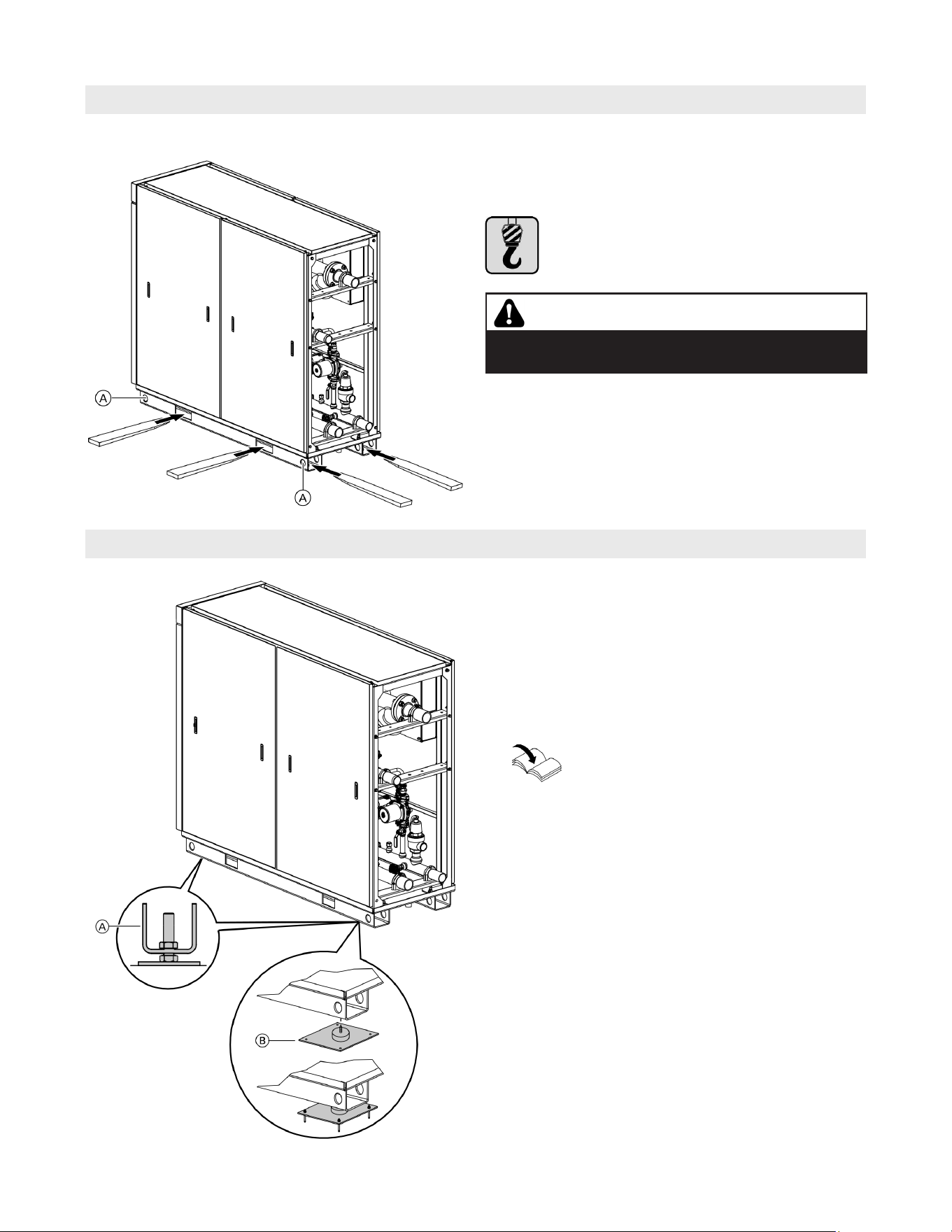
Preparing the Unit for Installation
Unpacking and Placing the Unit
1. Remove the Vitotrans from the wooden shipping
pallet. Remove the 4 leveling bolts A from boiler’s
accessory package and install into the four corners of
the boiler base.
Note: When using seismic brackets B (optional
accessory) do not install levelling bolts.
2. It is recommended to place a flat piece of steel plate
under each leveling bolt for better weight distribution
and adjustment.
3. Level the Vitotrans 300 with a slight slope towards
the base pan drain opening, by adjusting the floor
levelling bolts.
Note: It is recommended that the levelling bolts included
with the boiler are used when installing the
Vitotrans on uneven surfaces.
Refer to the Seismic bracket Installation
Instructions when using the optional seismic
mounts.
It is essential to use appropriate lifting devices
certified for lifting to a minimum of the Vitotrans
weight.
Remove the packaging from the Vitotrans.
The Vitotrans can be positioned using a forklift, using
the openings provided on the front, rear and sides.
CAUTION
Take care to ensure unit is not damaged by the forklift
during lifting.
Legend
A Crane lifting provisions (two on each side)
19
5833 275 - 07
Vitotrans 300 Installation, Operating and Service
Installation
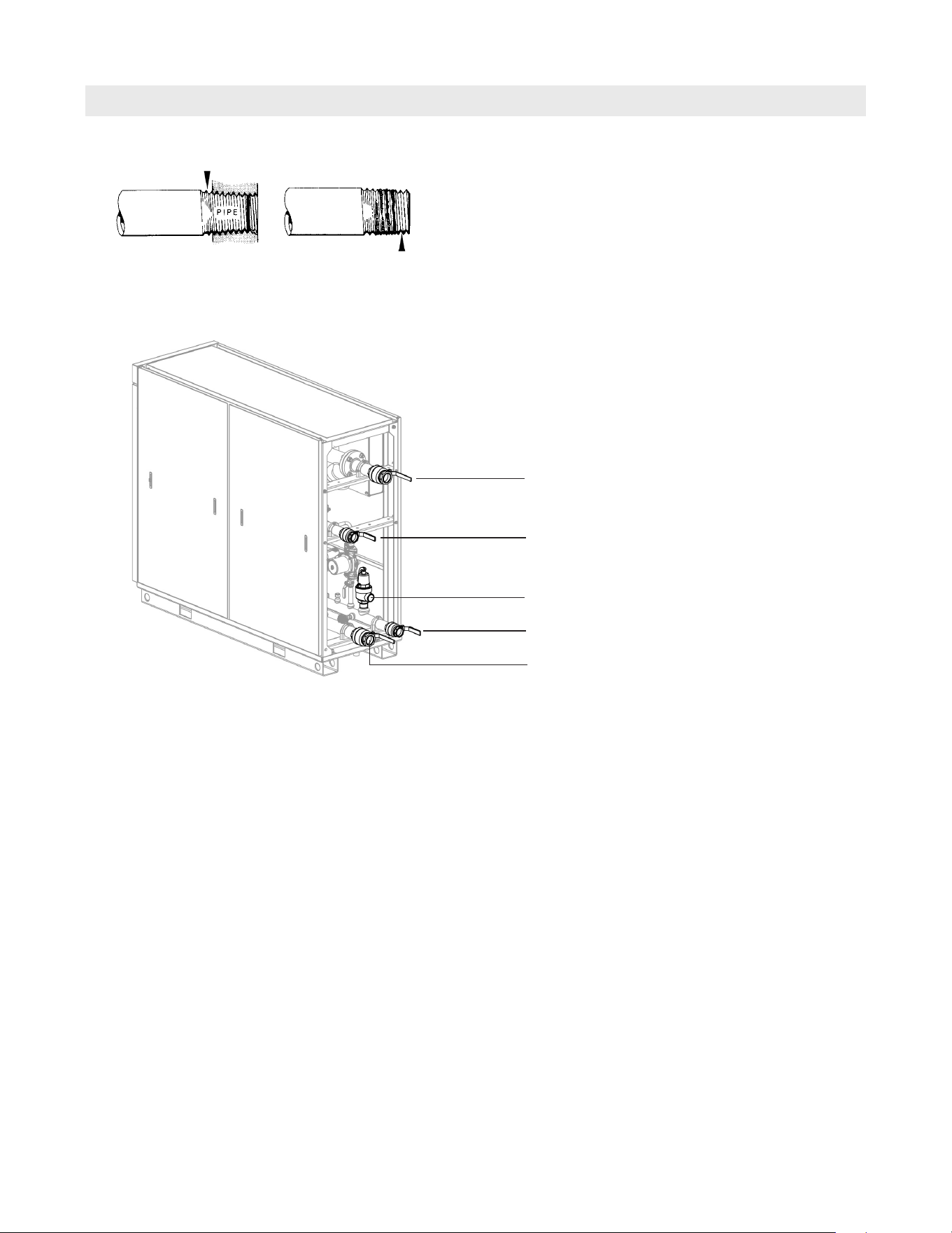
Installation Fittings
When installing the supplied valves to the domestic cold
water supply and the domestic hot water supply of the
Vitotrans 300 it is recommended that a thread sealant
specifically for use with stainless steel pipe is used.
Proper piping practice
Support piping by proper suspension method.
Piping must not rest on or be supported by Vitotrans.
2 imperfect threads
Leave 2 threads bare
Heating system supply
Domestic Cold water supply
Pressure relief valve (PRV)
Domestic Hot water
Heating system return
20
5833 275 - 07
Vitotrans 300 Installation, Operating and Service
Installation
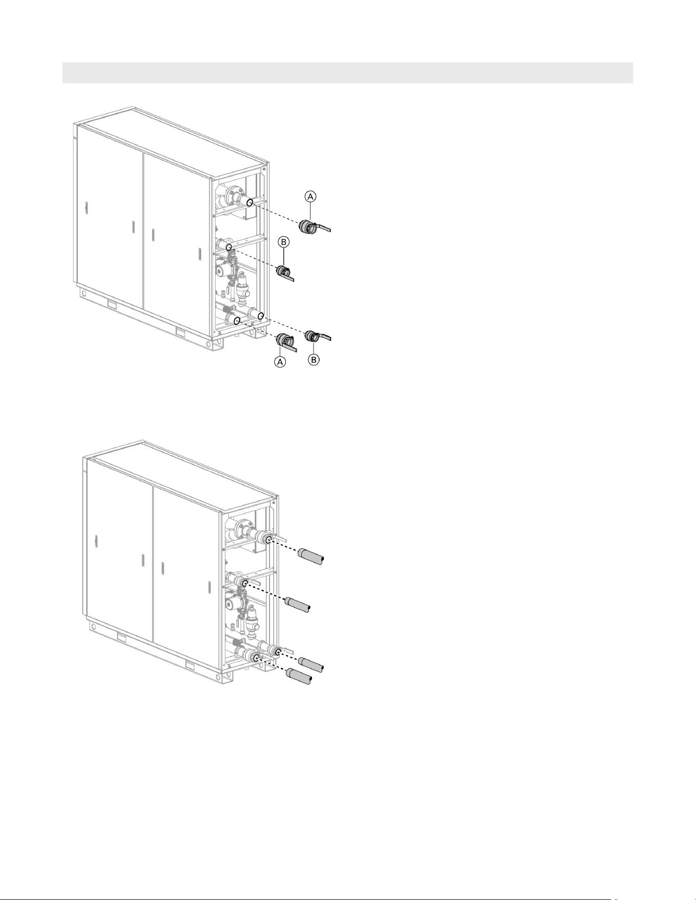
Waterside Connections
Note: Make all connections free of load and torque stresses.
The heating system must be properly flushed, especially if
the Vitotrans is connected to an existing heating system
in a retrofit application.
Connect the system to the Vitotrans according to the
diagram starting on page 8.
Legend
A 2b in. heating system valve
B 2 in. low lead domestic water valve
1. Install the heating system supply and return valves A.
2. Install the domestic hot and domestic cold water
valves B.
21
5833 275 - 07
Vitotrans 300 Installation, Operating and Service
Installation
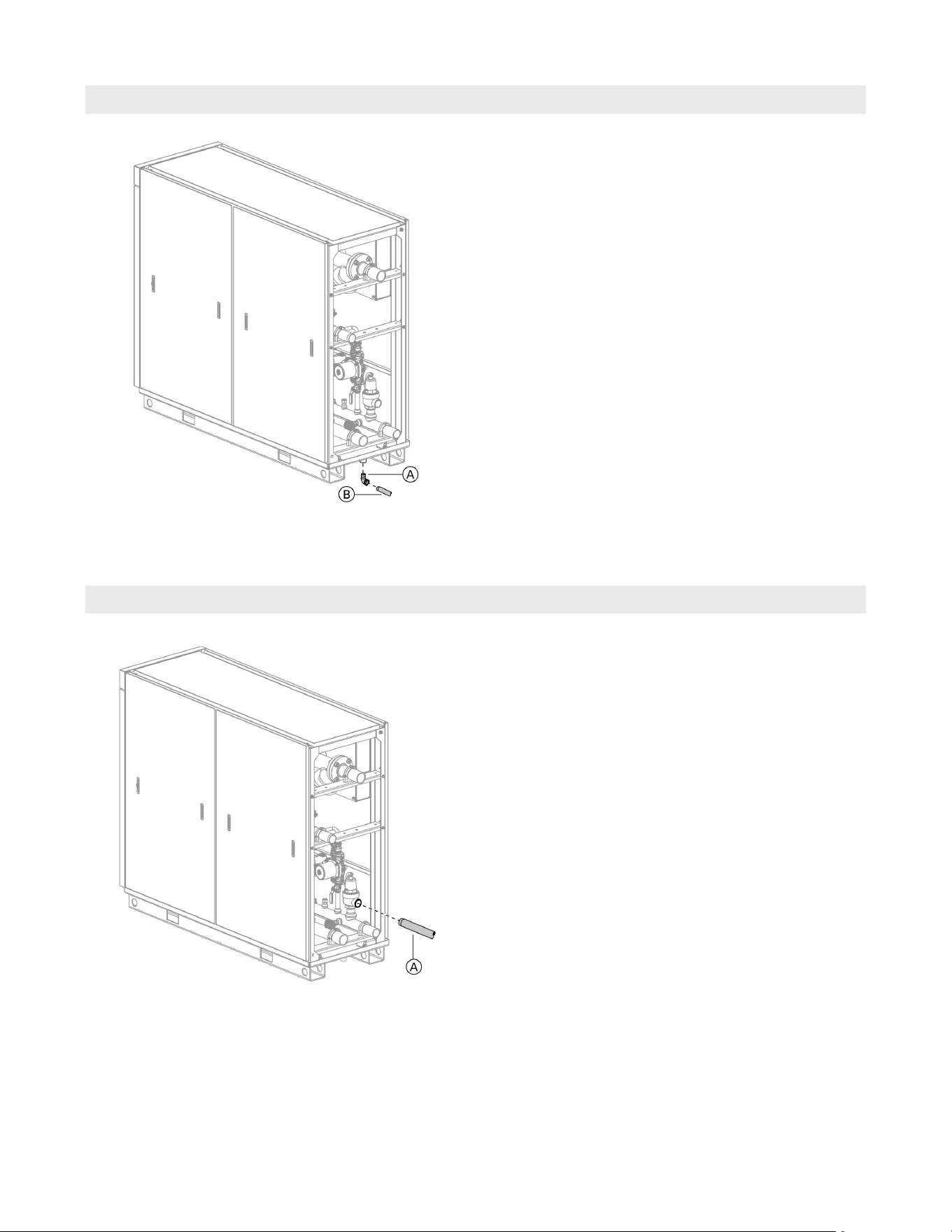
Drain Connection
Pressure Relief Valve Connection
Legend
A c in. street elbow
B c in. pipe
Legend
A 1b in. pipe
Note: Pipe and fittings are field supplied.
Note: Pipe and fittings are field supplied.
No valve, shut-off device or obstruction of any kind must
be used on the discharge side of the pressure relief valve.
The discharge side of the pressure relief valve must continue
out of the rear of the Vitotrans in the same size as the outlet
horizontally and then vertically downwards to end approx.
1 ft. (300 mm) above the floor and piped as close to a floor
drain as possible. Do not install this discharge pipe to the
outdoors or any area where freezing might occur or the
discharge pipe could endanger life and equipment.
1. Connect the piping A and B to the Vitotrans drip
pan and then to the floor drain.
22
5833 275 - 07
Vitotrans 300 Installation, Operating and Service
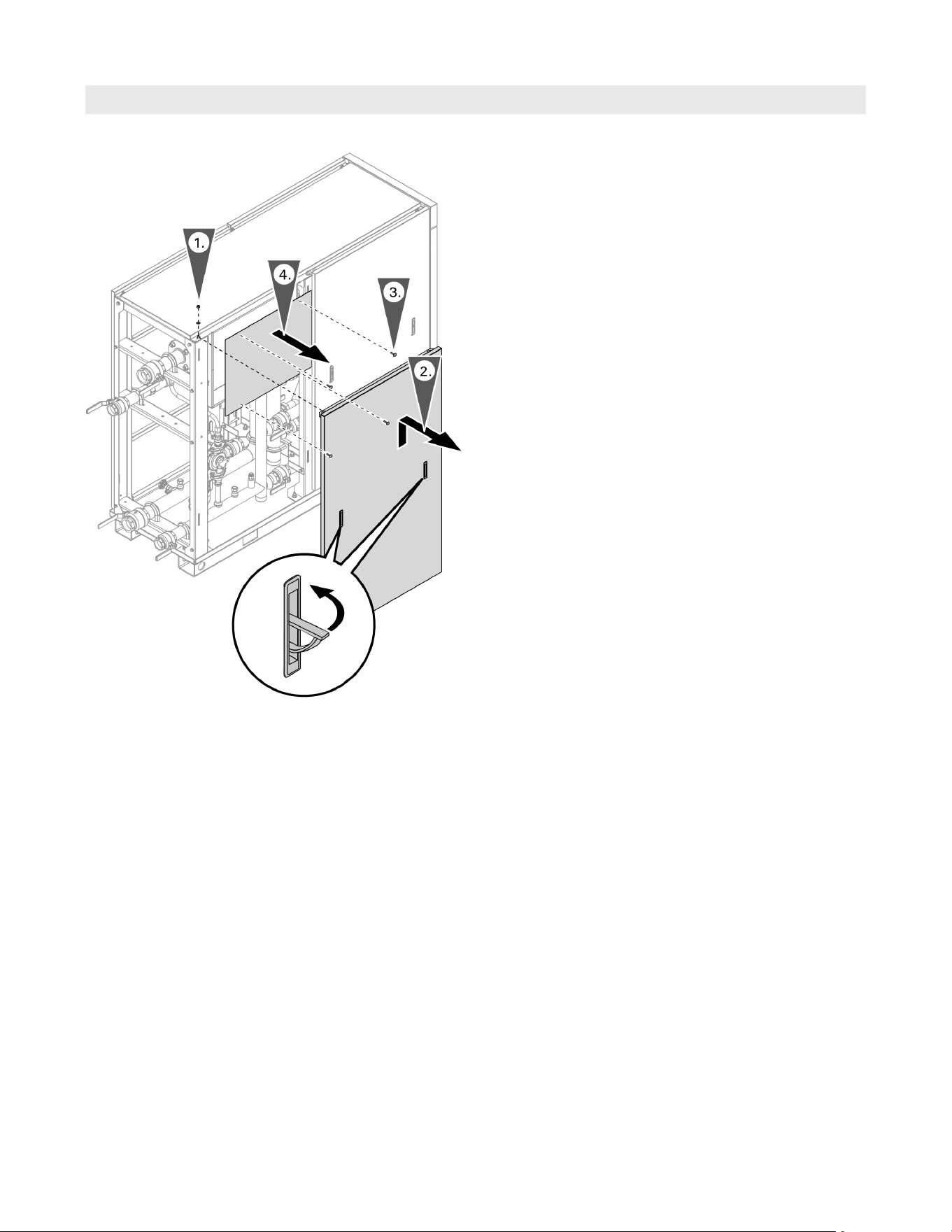
Installation
Electrical Connections
1. Remove left rear side panel retaining nut and washer.
2. Lift left rear side panel handles and remove panel.
3. Remove junction box retaining screws.
4. Remove junction box cover panel.
Accessing the junction box
23
5833 275 - 07
Vitotrans 300 Installation, Operating and Service
Installation
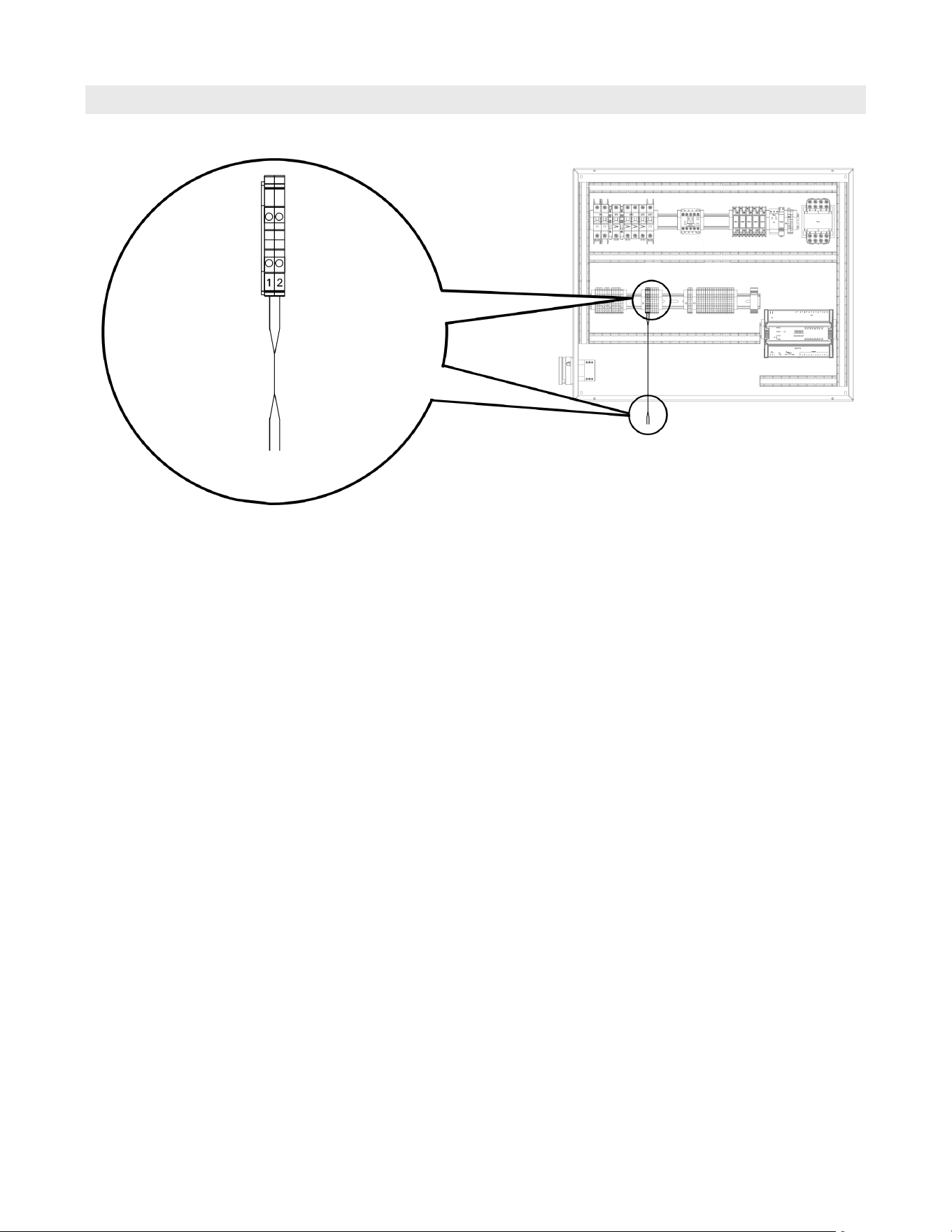
Electrical Connections (continued)
Connect the heat demand dry contacts from terminal
block X2 terminals 1 and 2 to the external demand of
the heat source control (building management system
or heating system).
When installing multiple Vitotrans, wire the heat
demand contact from each Vitotrans in parallel to the
heat source control (building management system or
heating system).
Terminal
Block X2
Dry contact
heat demand
to building
management
system
or heating system
Heat demand
The system heat source (boiler) should be set to supply
water to the Vitotrans 300 at least 20ºF (11ºC) higher
than the desired DHW setpoint.
24
5833 275 - 07
Vitotrans 300 Installation, Operating and Service
Installation
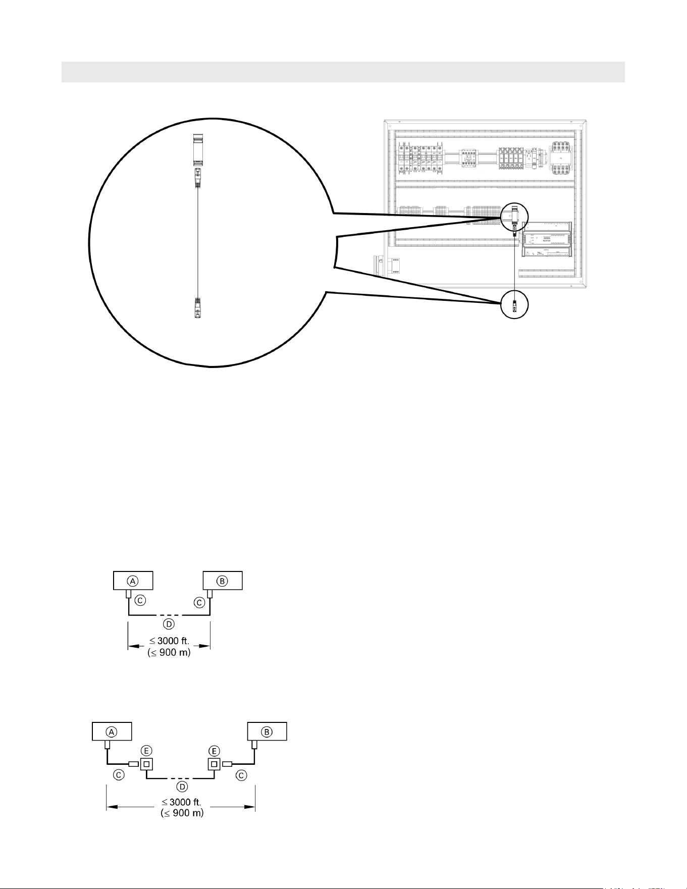
Electrical Connections (continued)
Product information
The integrated BACnet (IP) allows the Vitotrans
to be directly integrated into the BMS system.
The Vitotrans must be integrated into the BACnet control
system by an authorized contractor.
To BACnet
control system
BACnet communication
Functions
The integrated BACnet (IP) of the Vitotrans 300 enables
system users to utilize the following functions in
conjunction with a BACnet control system:
H Setting heating system parameters (temperature setpoint)
H Relaying fault and error messages
H Usage trends (temperature and flow rates for both
heating system and DHW)
Connection with on-site cable and RJ45 plug
Installation spacing ≤3000 ft.(≤900 m)
(with RJ45 connector)
Connection with RJ45 cable, on-site cable and RJ45 socket
Installation spacing ≤3000 ft.(≤ 900 m) (with RJ45 sockets)
Legend
A Vitotrans 300
B BACnet (IP) BMS system
C RJ45 male plug end
D On-site cable (field supplied)
Legend
A Vitotrans 300
B BACnet (IP) BMS system
C LON cable (field supplied)
D On-site cable (field supplied)
E RJ45 sockets
All Viessmann appliances are connected with RJ45
connectors.
Note: When connecting devices and routing cables,
observe the relevant safety requirements.
Ensure the safe electrical separation of all on-site
components (including PC/laptops).
The transfer distances for LON are subject to the electrical
properties of the respective cable. For this reason, only
use the specified cable types. Use only one cable type
within each LON.
H 2-core cable, CAT5, screened
Cable types (on site):
25
5833 275 - 07
Vitotrans 300 Installation, Operating and Service
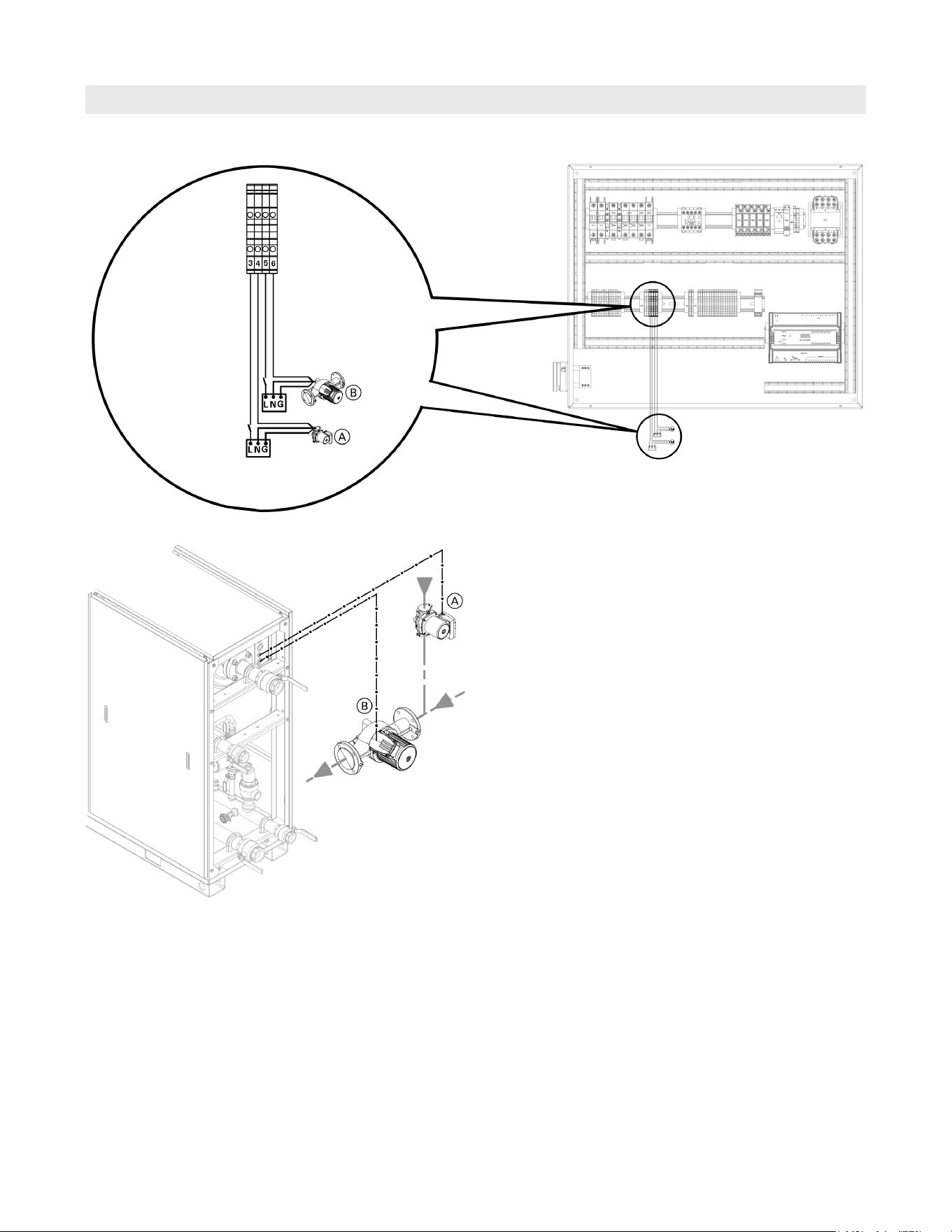
Electrical Connections (continued)
Pump connections for systems with a DHW storage tank
Terminal
Block X2
Provide
disconnect
means and
overload
protection
as required.
Power
Supplies
Legend
A Building DHW re-circulation pump (field supplied)
(Vitotrans terminal block X2, terminals 3 and 4)
(Power supply 120VAC/1Ph/60Hz, Max. 2 FLA
thru contacts)
B DHW DHW storage tank loading pump (field supplied)
(Vitotrans terminal block X2, terminals 5 and 6)
(Power supply 120VAC/1Ph/60Hz, Max. 2 FLA
thru contacts)
Note: See complete system layouts starting on page 8.
Note: The dry contact relays for the DHW tank loading
pump and DHW re-circ pump have a maximum rating
of 2 FLA. Pumps exceeding this rating will require
field supplied motor starter, contactor or relay.
Installation
26
5833 275 - 07
Vitotrans 300 Installation, Operating and Service
Installation
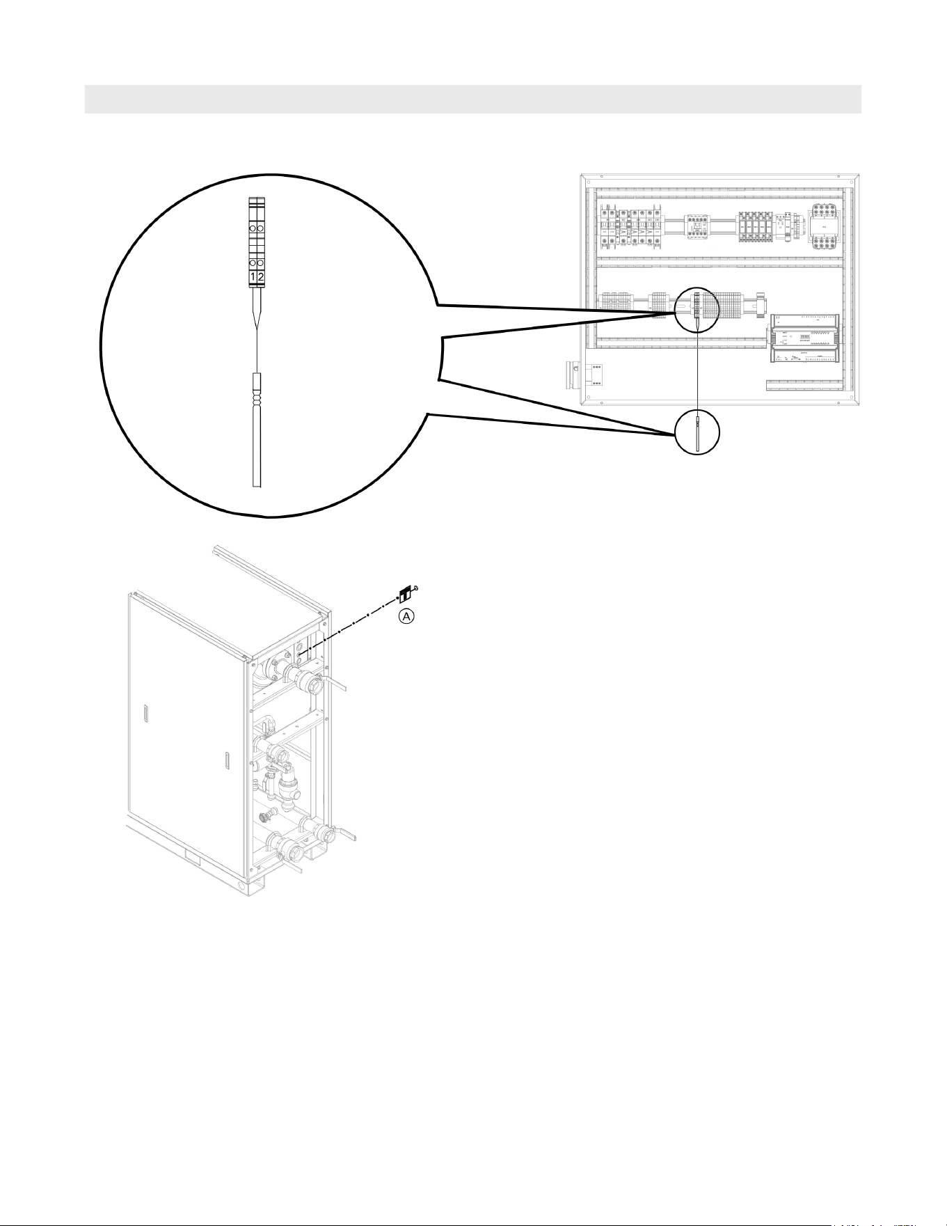
Electrical Connections (continued)
Legend
A DHW DHW storage tank temperature sensor
(terminal block X3, terminals 1 and 2)
Note: See complete system layouts starting on page 8.
Temperature sensor for systems with a DHW storage tank
Terminal
Block X3
DHW storage tank
temperature
sensor
27
5833 275 - 07
Vitotrans 300 Installation, Operating and Service
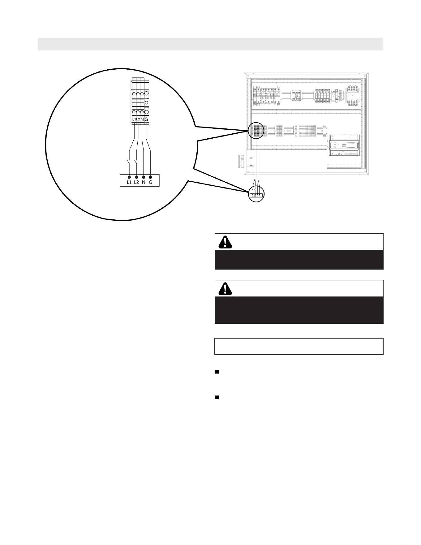
Electrical Connections (continued)
Installation
WARNING
Incorrectly executed electrical installations can lead to
injuries from electrical current and result in appliance
damage.
WARNING
The control must be grounded.
Ensure that ‘L’, ‘N’ and ‘G’ are not interchanged.
IMPORTANT
Electrical installations must comply with the latest edition of:
In the U.S.A., the National Electrical Code (NEC),
ANSI/NFPA 70 and any other state, local codes and/or
regulations.
In Canada, the Canadian Electrical Code (CEC),
CSA C22.1 Part 1 and any other province, territory,
local codes and/or regulations.
Provide disconnect
means and overload
protection as required.
Power Supply
120/208-240VAC/1Ph/60Hz
L1/L2/N/G
20 Amps (full load Amperage)
Terminal
Block X1
Main power supply

28
5833 275 - 07
Vitotrans 300 Installation, Operating and Service
Installation
Electrical Connections (continued)
1. Reinstall junction box cover panel.
2. Secure cover panel with retaining screws.
3. Position side panel using handles (bottom first).
4. Secure panel with retaining nut and washer and close
handle.
Closing the junction box
29
5833 275 - 07
Vitotrans 300 Installation, Operating and Service
Installation
Initial System Fill
Please observe that an antifreeze/water mixture may
require a backflow preventer within the automatic water
feed and influence components such as diaphragm
expansion tanks, radiation etc. A 40% antifreeze content
will provide freeze-up protection to -10°F (-23°C).
The Vitotrans 300 is only suitable for closed hot water
heating systems with pumps.
IMPORTANT
CAUTION
Before the Vitotrans is installed and piped into an
existing system, the heating system itself must be
properly flushed to remove dirt and system sludge.
Accumulations in old heating systems will tend to settle
in the Vitotrans and can lead to deposits which can
cause hot spots, noise and water-side corrosion. For
damages resulting from those kinds of impurities, the
warranty will be null and void.
Cold water fill pressure must equal expansion tank pressure.
The Vitotrans should be filled and properly bled of air and
the cold water fill pressure should not exceed 18-20 psig.
All openings, as well as pipe connections on the Vitotrans,
should be observed for possible leaks.
WARNING
Fill only suitable water in boiler. Unsuitable water
quality may damage the Vitotrans. Refer to the boiler
manufactures requirements.
IMPORTANT
Only use antifreeze specific for hydronic heating
systems. Do not use automotive glycol!
Heating system water quality
Domestic (potable) water quality
CAUTION
Before the Vitotrans is installed and piped into an
existing system, the heating system itself must be
properly flushed to remove dirt and system sludge.
Accumulations in old heating systems will tend to settle
in the Vitotrans and can lead to deposits which can
cause hot spots, noise and water-side corrosion. For
damages resulting from those kinds of impurities, the
warranty will be null and void.
Secure the discharge piping from the pressure relief valve
with the appropriate hangers or brackets.
IMPORTANT
The Vitotrans should be filled and properly bled of air and
the cold water fill pressure should not exceed 18-20 psig.
All openings, as well as pipe connections on the Vitotrans,
should be observed for possible leaks.
Water treatment should be considered in areas with
known problems, such as where a high mineral content
and hardness exist (see chart below).
Water Content Concentration
Chlorides <200 ppm
pH 6.0 - 9.0
Total hardness CACO
3
150 ppm
WARNING
Working on pressure loaded parts can be dangerous.
Connections around the heating water should only be
opened if the Vitotrans is unpressurized.
CAUTION
Under-pressure in the Vitotrans can lead to material
damages. Only empty Vitotrans with open ventilation
with a suction pump.
IMPORTANT
Checking Heating Water Connections for Leakage
Ensure that connections for control equipment and
minimum pressure monitor (low-water indicator) are also
leakage-free.
Treatment of boiler feed water should be considered in
areas of known problems, such as high mineral content and
hardness. In areas where freezing might occur, an antifreeze
may be added to the system water to protect the system
(maximum mix ratio - 50% / 50%). Please adhere to the
specifications given by the antifreeze manufacturer for
hydronic heating systems.
30
5833 275 - 07
Vitotrans 300 Installation, Operating and Service
Installation
Commissioning and Initial Start-up
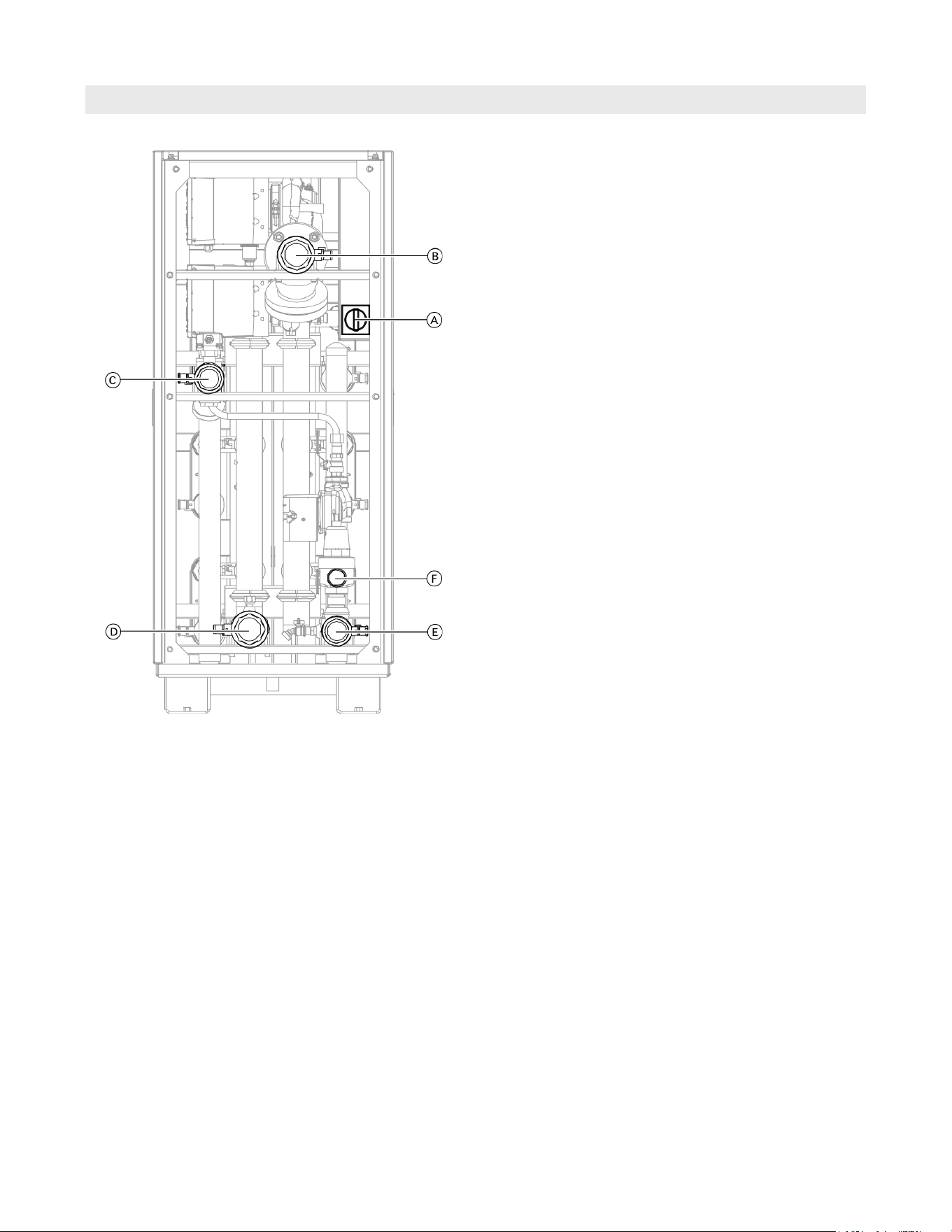
Legend
A Main power switch
B Heating system supply valve
C Domestic cold water (DCW) valve
D Heating system return valve
E Domestic hot water (DHW) valve
F Pressure relief valve
1. Open the hydronic connection pottable water valves
C and E.
2. Verify the proper operation of the pressure relief
valve F.
3. Open the heating system valves B and D.
4. Turn the Vitotrans main power switch A to the ON
position.
5.
Check all gaskets and plugs, and retighten if necessary.
Note: Check all connections on the heating water side
for leaks approx. every 500 operating hours.
Note: Check the heating system pressure.
Maximum operating pressure: ......... 150 psi (10.3 bar)
Minimum operating pressure: .............. 13 psi (0.9 bar)
31
5833 275 - 07
Vitotrans 300 Installation, Operating and Service
User Interface
Installation
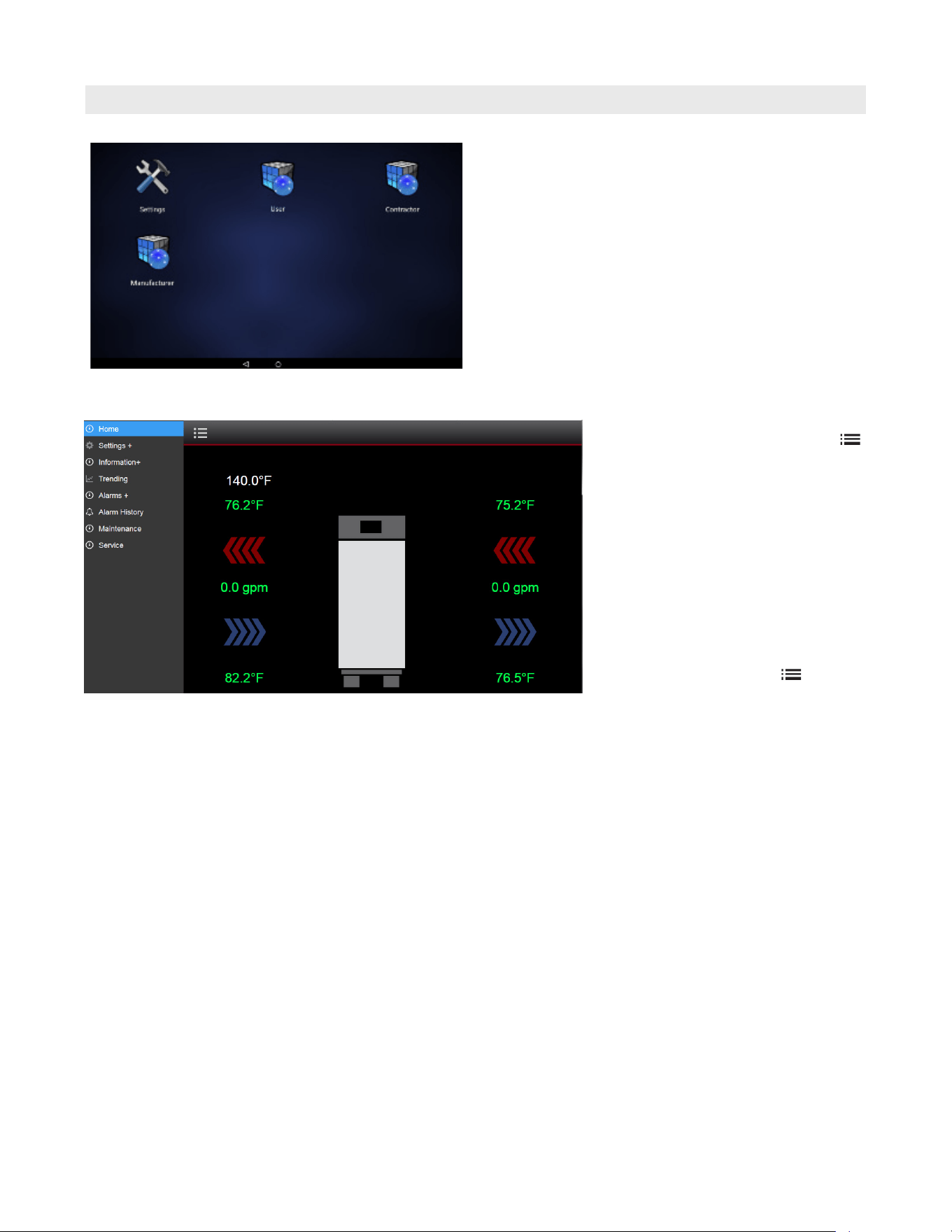
From the home screen select menu .
From the menu select Settings +.
The ‘settings +’ screen will provide
access to system setpoints required
for the initial set-up and configuration
of the Vitotrans 300, based on system
layout, temperature requirements and
time schedules.
Note: The Vitotrans 300 is factory set
to imperial units.
You can return to the home screen at
any time by selecting menu then
select Home.
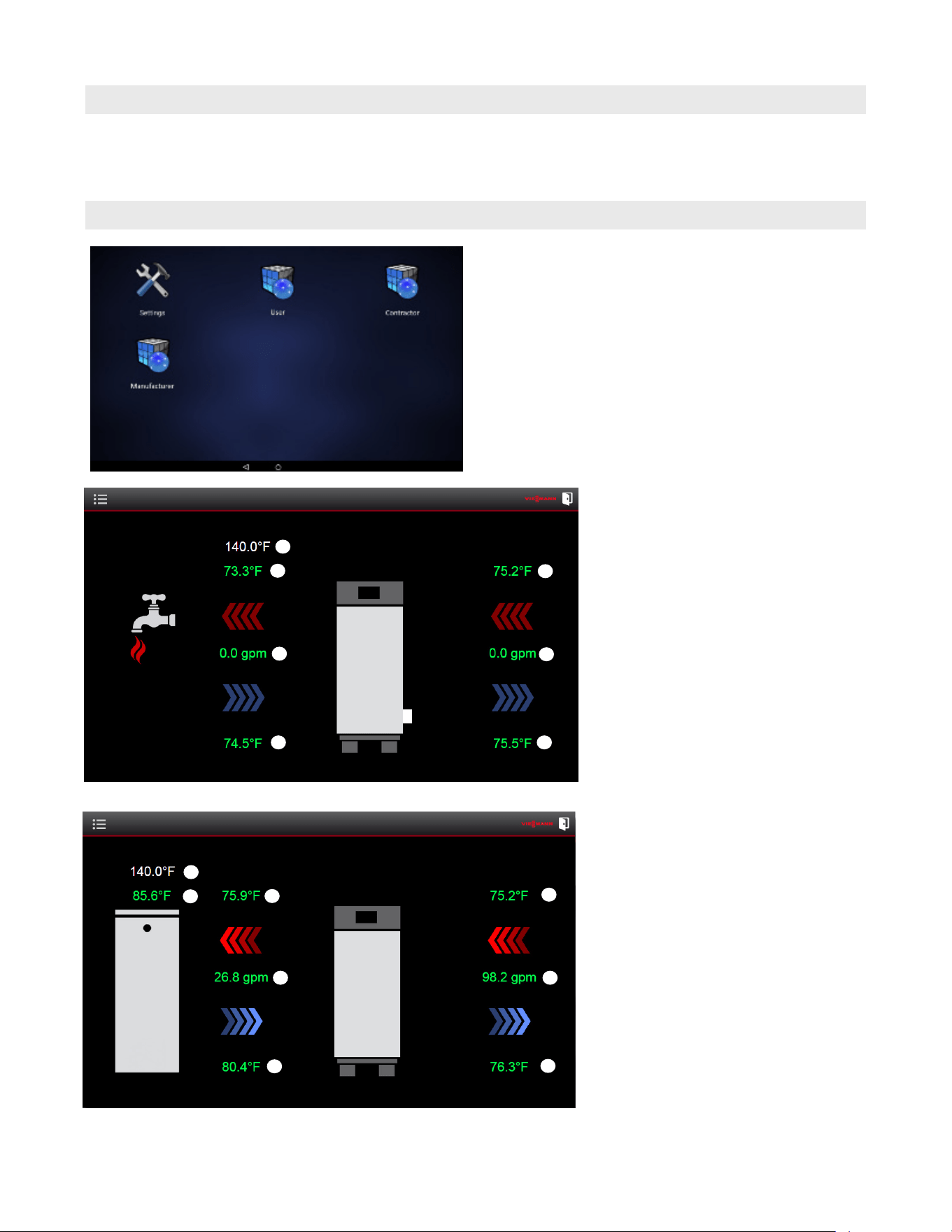
Log into the system by tapping the icon for the desired
level of system access, no password is required for user
level access. Service level access is password protected;
Service level password: viservice
To switch access levels, tap the circle icon located at
the bottom of the screen to return to login screen.
The setting icon on the home screen is for adjustment
of the screen settings only – do not adjust.
32
5833 275 - 07
Vitotrans 300 Installation, Operating and Service
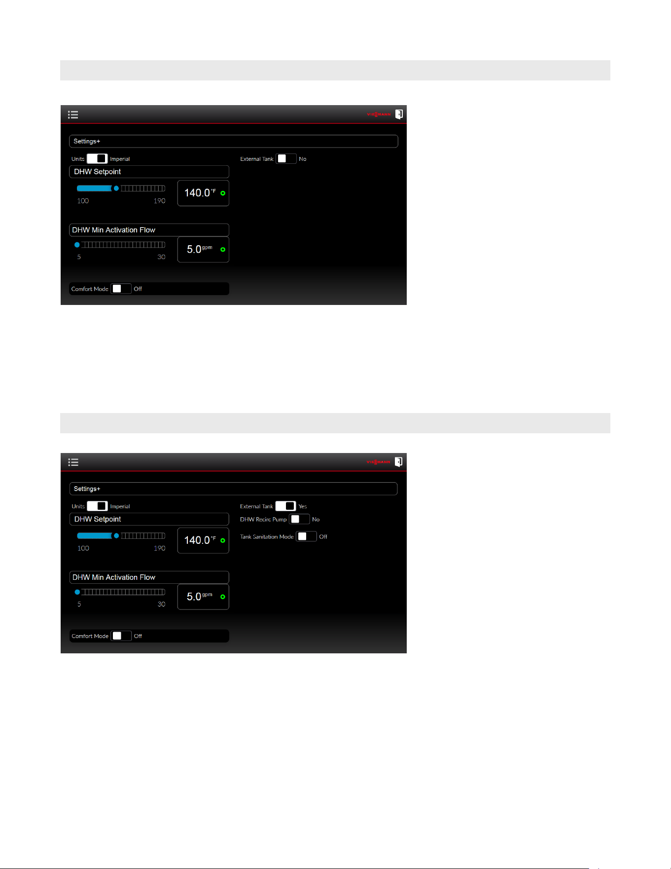
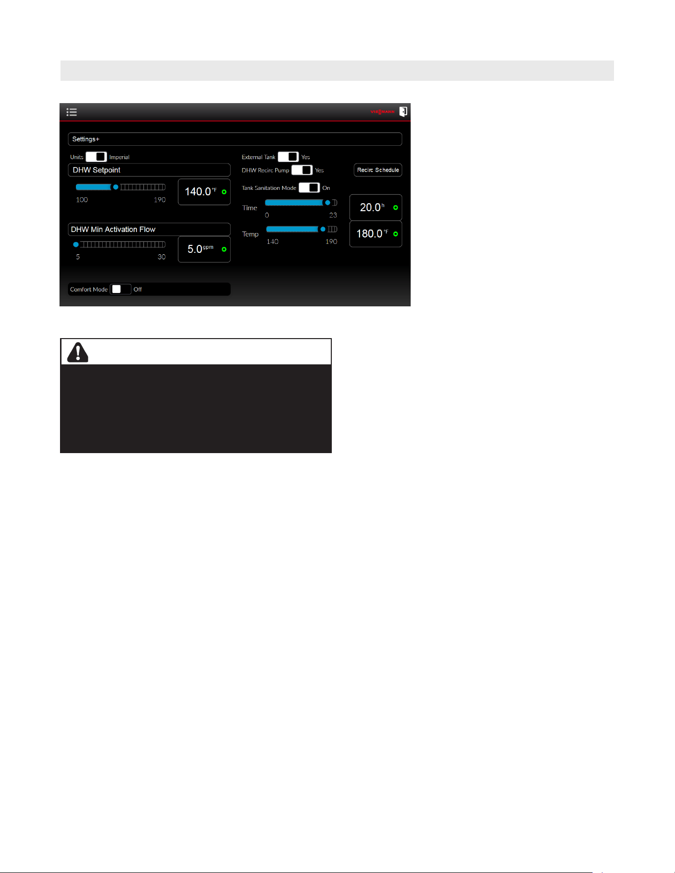
External Tank – When the external tank
is switched to ‘Yes’, this allows the
Vitotrans 300 to be set up for operation
with an external DHW storage tank
(See the recommended system layouts -
starting on page 8).
When the ‘external tank’ function is set in
the ‘yes’ position, the tank loading pump
output is activated. The tank loading
pump is connected to the control as
shown on page 25.
The option for a building DHW
recirculation pump and sanitation function
will also become available and display on
the Settings + screen.
Note: A DHW storage tank is highly
recommended for applications
where fluctuating DHW system
flow rates, particularly those flow
rates below 30 GPM (114 L/min)
for all Vitotrans 300 models sizes.
Installation
Instantaneous
DHW DHW Storage Tank
Units – The Units switch can be toggled to
change between Imperial units (ºF / GPM)
and Metric units (ºC / L/min.).
DHW Setpoint – This is the DHW setpoint
adjustable from 100ºF to 190ºF (38ºC to
88ºC). Drag the slider to adjust the DHW
setpoint.
DHW Min Activation Flow – This is the
minimum flow rate of domestic water that
is required to activate the Vitotrans 300.
This is adjustable from 5 GPM to 30 GPM
(19 L/min to 114 L/min). Drag the slider to
adjust the DHW min. activation flow.
Comfort mode
When the Vitotrans 300 is in standby,
this function will run the internal system
pump at a constant minimum speed.
This function can be used with a heating
system or boiler that is set up to maintain
a certain minimum system temperature.
This is to ensure that hot water is always
available at the Vitotrans 300 and that
DHW can be produced without delay.
33
5833 275 - 07
Vitotrans 300 Installation, Operating and Service
DHW Recirculation Pump
Installation
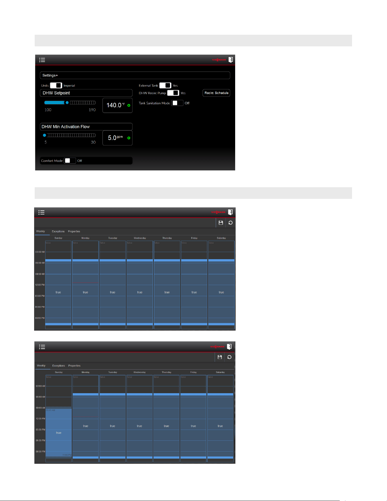
Recirc Schedule – Once the ‘Recirc
Schedule’ is selected, a 7-day schedule
will be displayed. Each day can be
programmed with its own single or
multiple unique run times.
The exceptions and properties tabs
contain no usable functions.
To adjust the schedule, drag the top or
bottom blue edge (for each day) to adjust
the start and stop times.
Time Schedule
DHW Recirc Pump – This option is only
available if external tank function has been
selected. When the ‘DHW recirc pump’ is
set in the yes position, the pump will run
according to the set time schedule.
To set the recirculation pump schedule tap
‘Recirc Schedule’.
34
5833 275 - 07
Vitotrans 300 Installation, Operating and Service
Installation
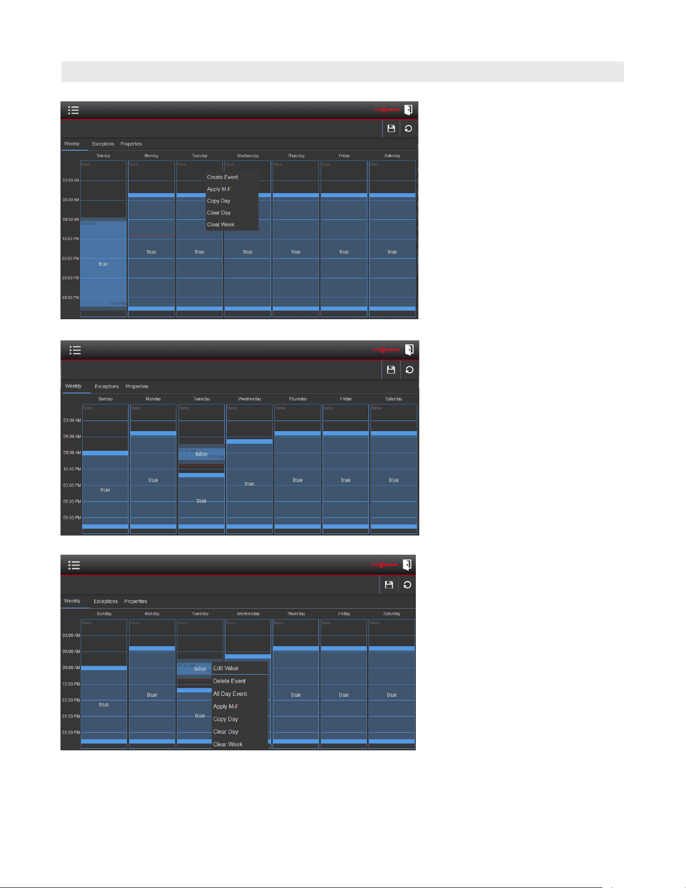
Time Schedule (continued)
To add additional run times per day,
touch and hold on the desired day
outside of the blue area. When the pop-
up menu appears, select “Create Event”.
Once the second event is adjusted to
the desired time, press and hold within
the blue area of that event and select
Edit Value to change the run time to
“true” for the new time made above.
A block of time will appear for the
day you selected and it will read false.
Adjust the start and stop times for that
block by dragging the top or bottom
blue edge.
Note: The new run time will not take
effect if left as ‘false’.
35
5833 275 - 07
Vitotrans 300 Installation, Operating and Service
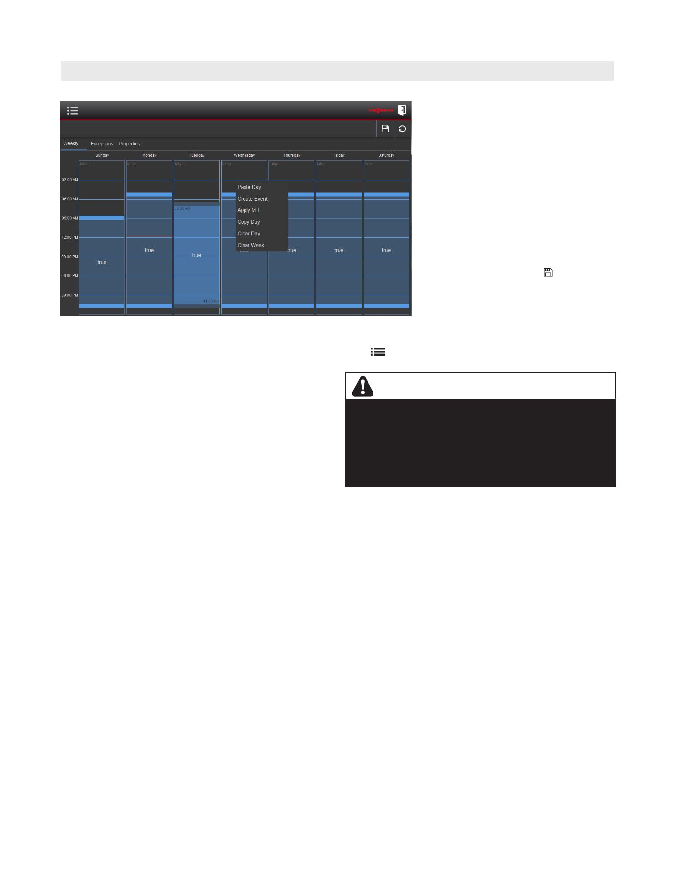
Time Schedule (continued)
Installation
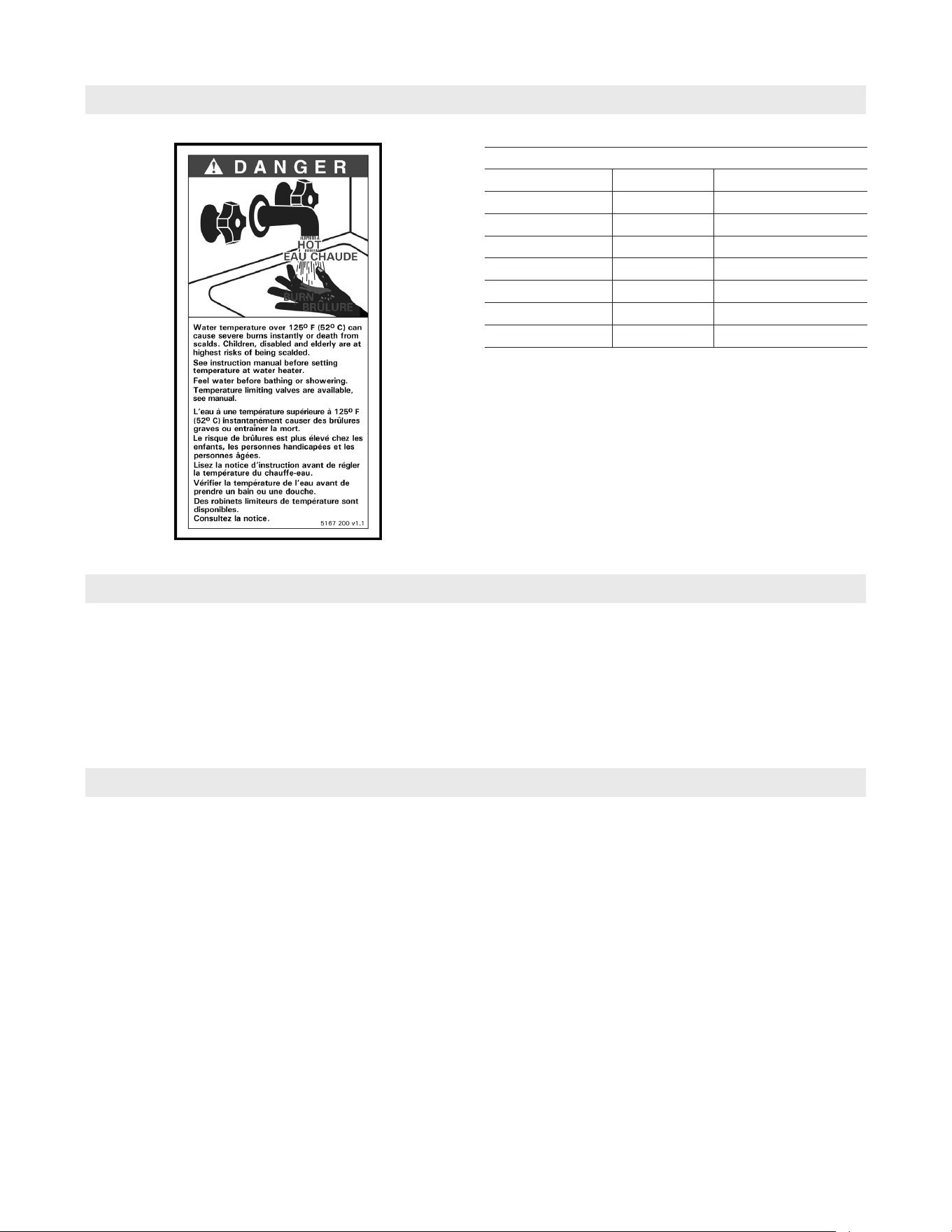
WARNING
Domestic hot water temperatures over 125°F (52°C) can
cause severe burns instantly or loss of life from scalds.
Children, disabled and elderly are at highest risk of being
scalded. Feel water before bathing or showering.
Temperature limiting valves are available and must be used
where domestic hot water temperatures exceed 140°F
(60°C).
If the same schedule is required for
multiple days, it can be set for one day,
then copied to other days. This can be
done by touching and holding on the day
outside of the blue area, then selecting
“Copy Day” from the pop-up menu. Touch
and hold on a day that requires the same
schedule and select “Paste Day”, the
schedule should be duplicated.
The exceptions and properties tabs
contain no usable functions.
When the weekly schedule has been
configured, press the Save button in
the upper right corner of the screen.
Note: To return to the ‘settings +’ screen select menu
then select Settings +.
36
5833 275 - 07
Vitotrans 300 Installation, Operating and Service
Installation
Sanitation Function
Sanitation function – When the ‘Tank
Sanitation Mode’ is set to ‘ON’, the
start time and temperature setpoint hours
will appear on the display. The Vitotrans
300 will perform a sanitation cycle for the
external tank once per day at the selected
time. Each cycle will increase the external
tank temperature above the DHW setpoint
to the sanitation function setpoint.
The cycle will end once the setpoint has
been reached or 1 hour has elapsed,
whichever comes first.
WARNING
Domestic hot water temperatures over 125°F (52°C) can
cause severe burns instantly or loss of life from scalds.
Children, disabled and elderly are at highest risk of being
scalded. Feel water before bathing or showering.
Temperature limiting valves are available and must be used
where domestic hot water temperatures exceed 140°F
(60°C).
Sanitation Time – This allows the selection of what time
each day the sanitation function will start. The adjustable
time slider selects the desired start time with 0 = 12:00 AM
and 23 = 11:00 PM. Choose a time of day where the DHW
draw from the external tank is expected to be minimal.
Sanitation Temperature – This is a temporary DHW tank
setpoint during the sanitation cycle. It can be set from
140ºF to 190ºF (60ºC to 88ºC). Once the sanitation
cycle is complete, the tank temperature will return to
the DHW setpoint temperature.
For proper operation the system supply temperature
must be at least 20ºF (11ºC) higher then the sanitation
setpoint temperature.
37
5833 275 - 07
Vitotrans 300 Installation, Operating and Service
Installation
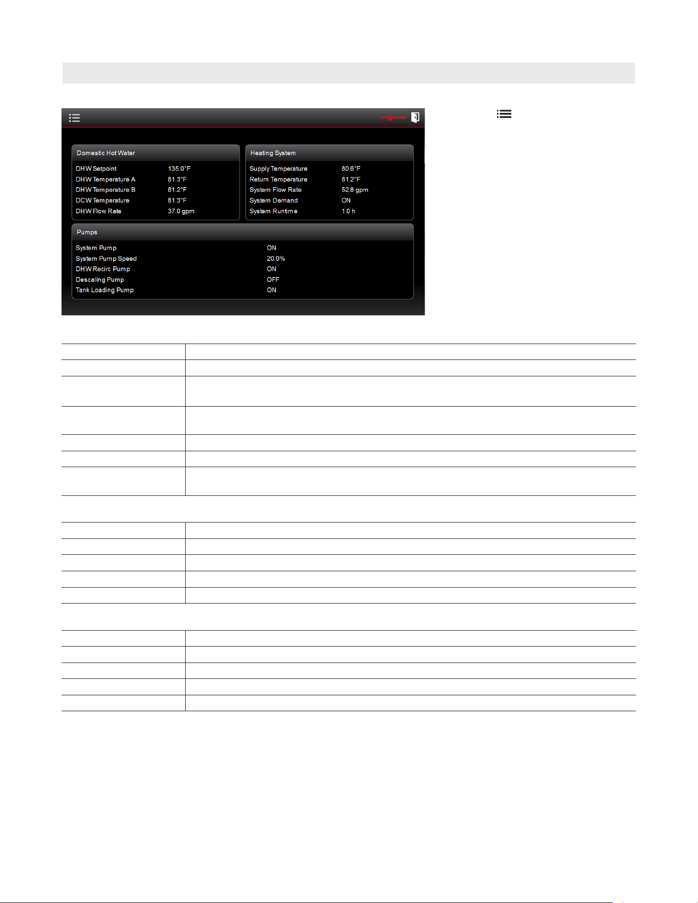
System Information
Select menu . then select the
Information + button to display the
Information screen. This screen displays
the current system operating status
(no adjustments can be made from this
screen).
Pumps
System Pump A Operational status of main system pump A, will run anytime there is demand for DHW.
System Pump A Speed Modulating signal to pump A (20%-80%)
System Pump B
(S3HA/D3HA 90 only)
Operational status of main system pump B, may run in conjunction with pump A when
there is demand for DHW.
System Pump B Speed
(S3HA/D3HA 90 only)
Modulating signal to pump B (20%-80%)
DHW Recirculation Operational signal for DHW recirculation pump, will activate according to set time schedule.
Descaling Pump Operational status of descaling pump, will run continuously whenever the unit is in standby.
Tank Loading Pump Operational signal for DHW storage tank loading pump, will activate when there is a
demand to recover the DHW storage tank.
Domestic Hot Water
DHW Setpoint Domestic hot water setpoint temperature
DHW Temperature A Dual sensor actual DHW temperature A
DHW Temperature B Dual sensor actual DHW temperature B
DCW Temperature Domestic cold water incoming temperature
DHW Flow Rate Actual domestic hot water draw rate
Heating System
Supply Temperature Actual heating system supply water temperature
Return Temperature Actual heating system return water temperature
System Flow Rate Actual heating system flow rate through the unit
System Demand Call for heat to the heating system
System Runtime Number of hours the system has been producing DHW
38
5833 275 - 07
Vitotrans 300 Installation, Operating and Service
Installation
Commissioning
Devices Required for Commissioning:
- PC Laptop with Ethernet port and
web browser application
- CAT5 / RJ45 network cable
1. Using the Network and Sharing
Center, set Internet Protocol
Version 4 (TCP/IPv4) to a static IP
address of 192.168.0.XX (use any
other than 50, 100, 101, 102).
2. Plug the network cable into the
RJ45 port located inside the
control panel of the Vitotrans 300.
(see page 24 for diagram of
control panel layout)
3. Open the web browser application
and type 192.168.0.100 into the
address bar.
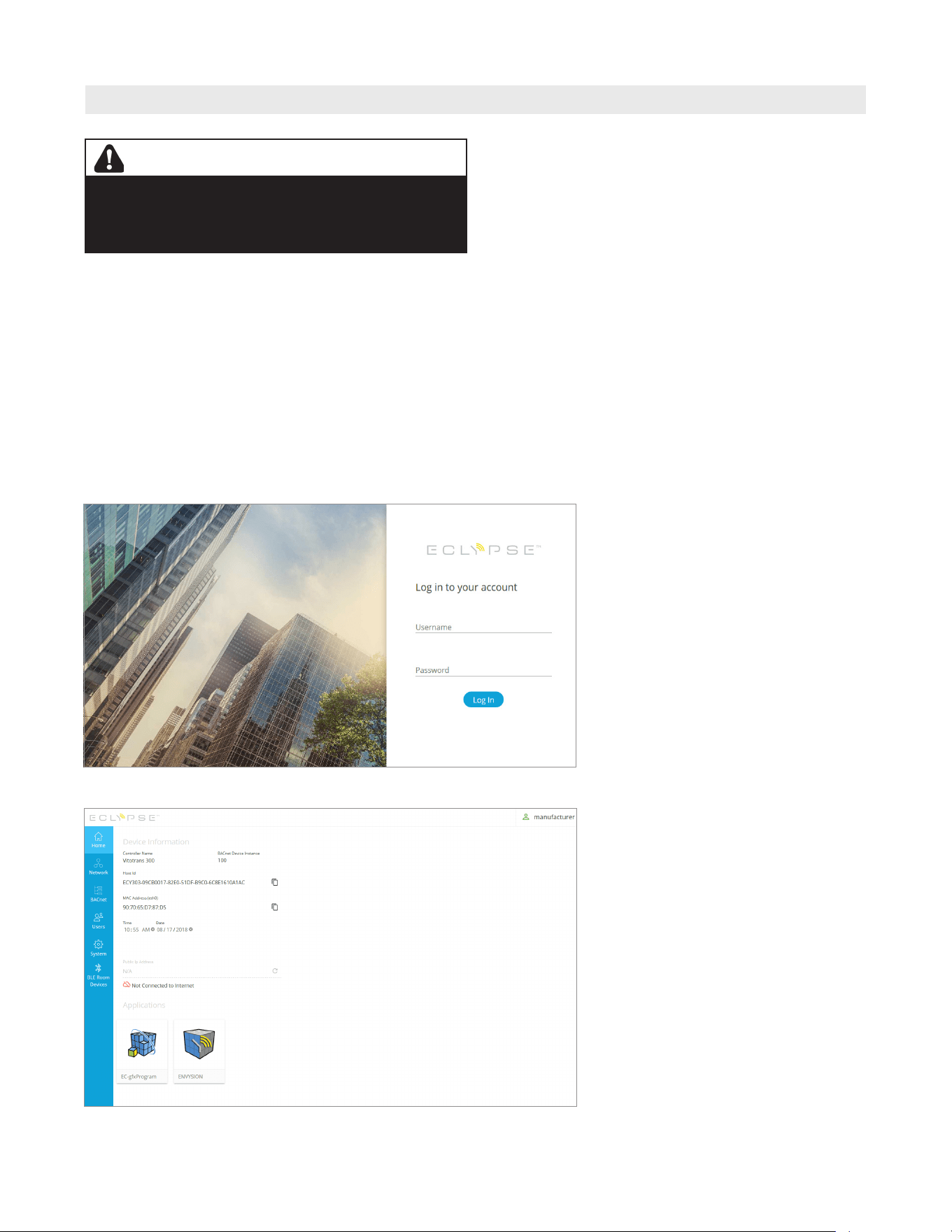
4. A login screen will appear, enter
the following information:
Username: manufacturer
Password: vimaster
WARNING
The MANUFACTURER access level allows for changes
to be made that can alter the function of the Vitotrans
300. Making changes other than what is detailed in
these instructions may result in unwanted operation.
5. Once logged in, a menu pane on
the left side of the screen will
display the following tabs, note the
actions that can be taken:
- Home: Displays general device
information, No Changes
can be made.
- Network: No Changes can be made
to any settings within
this tab.
- BACnet: Changes can be made,
see following steps.
- Users: No Changes can be made to
any settings within this tab.
- System: Changes can be made,
see following steps.
- BLE Room Devices: Not Applicable
39
5833 275 - 07
Vitotrans 300 Installation, Operating and Service
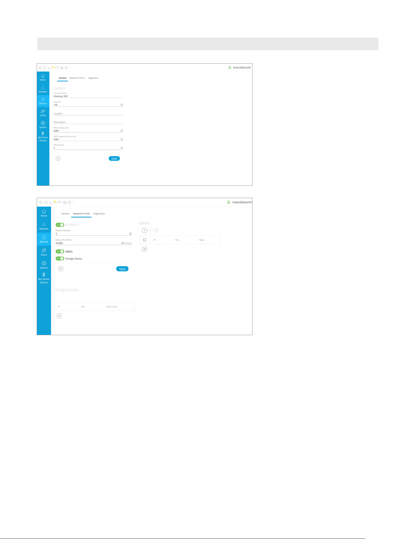
6. BACnet
- General: The “Controller Name”
and “Device ID” can be
changed.
Installation
Commissioning (continued)
- Network IP Ports:
H IP Port 1
H BBMD (BACnet/IP Broadcast
Management Device)
H Foreign Device
Use BBMD and Foreign Device when
communication with a different
network is required.
- Diagnostics: No Changes can be
made to the settings
within this tab.
(information only)
40
5833 275 - 07
Vitotrans 300 Installation, Operating and Service
Installation
Commissioning (continued)
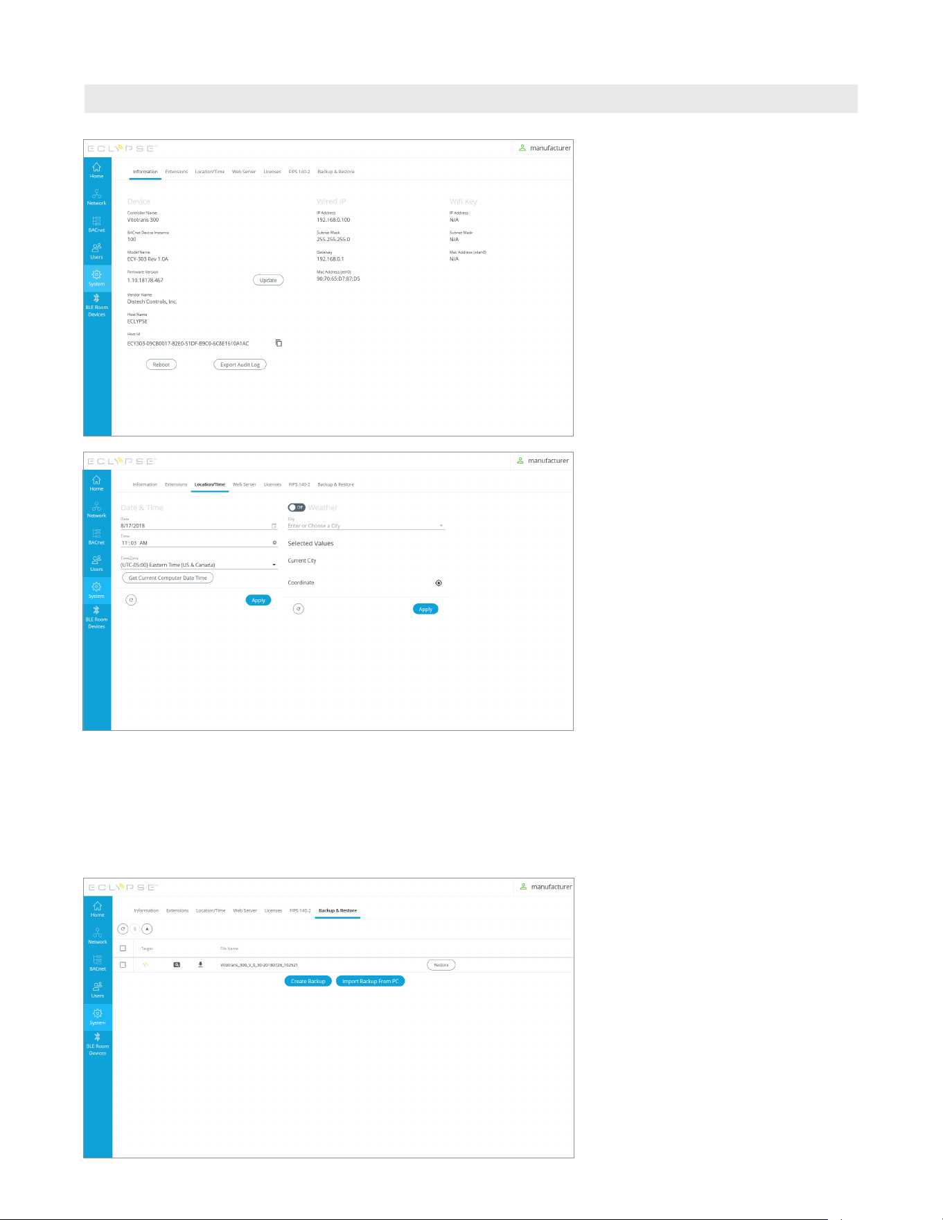
7. System
- Information: The controller
firmware can be
updated;
Contact Viessmann Service for
assistance with this function.
- Extensions: No Changes can be
made to the settings
within this tab.
- Location/Time: The date and time
can be updated by
clicking “Get Current
Computer Date
Time” then clicking
“Apply” This may
need to be done if
the Vitotrans 300 is
powered off for more
than 20 days or if it
is installed in a
different time zone.
The ”Weather”
function is not used
and remain off.
- Web Server: No Changes can be
made to the settings
within this tab.
- Licenses: No Changes can be made
to the settings within
this tab.
- FIPS 140-2: No Changes can be
made to the settings
within this tab.
- Backup & Restore:
Contact Viessmann Service for
assistance with this function.
- Log out when setup is complete

41
5833 275 - 07
Vitotrans 300 Installation, Operating and Service
Installation
Vitotrans 300 BACnet (IP) Points
Name Object ID Read / Write Note / Description
DHW Temp T1A analogInput:101 Read only DHW Dual Temp Sensor A (ºF)
DHW Temp T1B analogInput:102 Read only DHW Dual Temp Sensor B (ºF)
DCW Temp T2 analogInput:103 Read only DCW Temp Sensor (ºF)
Flow Rate DHW analogInput:104 Read only DHW Flow Rate (GPM)
Boiler Return Temp T4 analogInput:105 Read only System Return Temp Sensor (ºF)
External Tank Temp T5 analogInput:107 Read only DHW Storage Tank Temp Sensor (ºF)
Boiler Pump Speed P1A analogOutput:107 Writable Do Not Change
Boiler Pump Speed P1B analogOutput:108 Writable Do Not Change
DHW Stpt Temp analogValue:1 Read / Write DHW Setpoint Temp (100ºF-190ºF)
Min DHW Activation Flow analogValue:2 Read / Write DHW Min. Activation Flow (5-30GPM)
External Tank Differential analogValue:4 Read / Write Do Not Change
Tank Sanitize Stpt Temp analogValue:5 Read / Write Sanitize Function Setpoint Temp (140ºF-190ºF)
Tank Sanitize Time analogValue:6 Read / Write Sanitize Function Activation Time (0-23hr)
Number of HX analogValue:7 Read / Write Do Not Change
System Runtime analogValue:8 Read / Write System Runtime (hr)
Boiler Supply Temp T3 analogValue:10 Read / Write System Supply Temp Sensor (ºF)
Boiler Flow Rate analogValue:11 Read / Write System Flow Rate (GPM)
Pump P1 Head Pressure analogValue:12 Read / Write Do Not Change
DHW Temp T1A_C analogValue:20 Read / Write DHW Dual Temp Sensor A (ºC)
DCW Temp T2_C analogValue:21 Read / Write DCW Temp Sensor (ºC)
Boiler Return Temp T4_C analogValue:22 Read / Write System Return Temp Sensor (ºC)
External Tank Temp T5_C analogValue:23 Read / Write DHW Storage Tank Temp Sensor (ºC)
Flow Rate DHW_LPM analogValue:24 Read / Write DHW Flow Rate (LPM)
Boiler Supply Temp T3_C analogValue:25 Read / Write System Supply Temp Sensor (ºC)
Pump P1 Head Pressure_Bar analogValue:26 Read / Write Do Not Change
Flow Rate Boiler_LPM analogValue:27 Read / Write System Flow Rate (LPM)
DHW Temp T1B_C analogValue:28 Read / Write DHW Dual Temp Sensor B (ºF)
DHW Stpt Temp_C analogValue:31 Read / Write DHW Setpoint Temp (38ºC-88ºC)
Min DHW Activation Flow_LPM analogValue:32 Read / Write DHW Min. Activation Flow (19-114LPM)
External Tank Differential_C analogValue:33 Read / Write Do Not Change
Tank Sanitize Stpt Temp_C analogValue:34 Read / Write Sanitize Function Setpoint Temp (60ºC-88ºC)
PID DHW Stpt Input analogValue:10001 Read / Write Do Not Change
PID DHW Stpt Setpoint analogValue:10002 Read / Write Do Not Change
PID DHW Stpt Output analogValue:10003 Read / Write Do Not Change
PID P1 Limit Input analogValue:10011 Read / Write Do Not Change
PID P1 Limit Setpoint analogValue:10012 Read / Write Do Not Change
PID P1 Limit Output analogValue:10013 Read / Write Do Not Change
Safety High Limit binaryInput:106 Read only Do Not Change
Boiler Pump Cmd P1A binaryOutput:101 Writable Do Not Change
Internal Descaling Pump Cmd P2 binaryOutput:102 Writable Do Not Change
WARNING
Attempting to modify points listed as „Do Not Change“ will
result in undesired operation.

42
5833 275 - 07
Vitotrans 300 Installation, Operating and Service
Installation
Vitotrans 300 BACnet (IP) Points (continued)
Name Object ID Read / Write Note / Description
Boiler Dmd binaryOutput:103 Writable Do Not Change
DHW Recirc Pump Cmd binaryOutput:104 Writable Do Not Change
External Tank Loading Pump Cmd binaryOutput:105 Writable Do Not Change
Boiler Pump Cmd P1B binaryOutput:106 Writable Do Not Change
Language binaryValue:1 Read / Write Language (English / French) - DISABLED
Units binaryValue:2 Read / Write Units (Imperial / Metric)
External Tank binaryValue:3 Read / Write External DHW Storage Tank (No / Yes)
DHW Recirculation binaryValue:4 Read / Write DHW Recirculation Pump (No / Yes)
Reset Dead Lock binaryValue:6 Read / Write Do Not Change
Service 1 HX binaryValue:7 Read / Write Service Mode (No / Yes)
Comfort mode binaryValue:9 Read / Write Comfort Mode (No / Yes)
DHW Flow Presence binaryValue:11 Read / Write Do Not Change
Boiler Flow Presence binaryValue:12 Read / Write Do Not Change
Reset System Runtime binaryValue:13 Read / Write Do Not Change
Tank Sanitation Mode binaryValue:14 Read / Write Tank Sanitation Function (No / Yes)
Fault - System Pump Comms binaryValue:20 Read / Write System Pump Communication
(Normal / Fault)
Fault - DHW Flow Sensor binaryValue:21 Read / Write Flow Sensor (Normal / Fault)
Fault - System Pump Deadhead binaryValue:22 Read / Write System Pump Deadhead (Normal/Fault)
Fault - DHW Temp Sensor binaryValue:23 Read / Write DHW Temp Sensor (Normal / Fault)
Fault - Fixed High Limit binaryValue:24 Read / Write Fixed High Limit (Normal / Fault)
Fault - Fixed High Limit binaryValue:25 Read / Write DCW Temp Sensor (Normal / Fault)
Fault - System Return Temp Sensor binaryValue:26 Read / Write Return Temp Sensor (Normal / Fault)
Fault - DHW Tank Temp Sensor binaryValue:27 Read / Write Tank Temp Sensor (Normal / Fault)
Fault - General Fault binaryValue:30 Read / Write General Fault (Normal / Fault) -
generated by any fault
PID DHW Stpt loop:1 Read only Do Not Change
PID P1 Limit loop:2 Read only Do Not Change
Alarm_Class-notificationClass notificationClass:1 Read only Do Not Change
DHW Recirc Pump Schedule schedule:1 Read only Do Not Change
DHW Recirc Pump Schedule 1 schedule:2 Read only Do Not Change
Fault - System Pump multiStateValue:1 Read / Write System Pump Fault (Normal / Fault)
Warning - System Pump multiStateValue:2 Read / Write System Pump Warning (Normal / Fault)
DHW Temp T1A Trend Log-recordCount trendLog:100101 Read only Do Not Change
DCW Temp T2 Trend Log-recordCount trendLog:100103 Read only Do Not Change
Flow Rate DHW Trend Log-recordCount trendLog:100104 Read only Do Not Change
Boiler Return Temp T4 Trend Log-recordCount trendLog:100105 Read only Do Not Change
External Tank Temp T5 Trend Log-recordCount trendLog:100107 Read only Do Not Change
Boiler Supply Temp T3 Trend Log-recordCount trendLog:300010 Read only Do Not Change
Boiler Flow Rate Trend Log-recordCount trendLog:300011 Read only Do Not Change
DHW Temp T1A_C Trend Log-recordCount trendLog:300020 Read only Do Not Change
DCW Temp T2_C Trend Log-recordCount trendLog:300021 Read only Do Not Change
Boiler Return Temp T4_C Trend Log-recordCount trendLog:300022 Read only Do Not Change
External Tank Temp T5_C Trend Log-recordCount trendLog:300023 Read only Do Not Change
Boiler Supply Temp T3_C Trend Log-recordCount trendLog:300025 Read only Do Not Change
Flow Rate Boiler_LPM Trend Log-recordCount trendLog:300027 Read only Do Not Change
43
5833 275 - 07
Vitotrans 300 Installation, Operating and Service
Overview
Domestic Hot Water Production
Ensure the instructions and requirements
of the boiler control and system accessories
are observed.
Domestic hot water production can occur via heating
boiler or a remote heating plant.
The maximum heating supply temperature is 230°F
(110°C), the maximum operating pressure is 150 psig.
Do not use steam.
Domestic hot water production
1. Set the desired domestic hot water temperature
140°F (60°C) for example) on the Vitotrans 300
control.
2. The boiler water supply temperature for domestic hot
water production is set on the heating system control.
It should be approximately 20°F (11°C) above the
desired domestic hot water temperature.
3. For your personal safety, we recommend the
installation of a tempering valve to restrict the entry
of excessively hot domestic hot water into the system.
Hire a qualified heating contractor.
IMPORTANT
Domestic hot water may be preheated or heated to
temperatures over 113°F (45°C) depending on system
energy output and temperature characteristics.
WARNING
The DHW fixed high limit is factory set to 210°F (99°C).
Do Not Ajust!
WARNING
Domestic hot water temperatures over 125°F (52°C) can
cause severe burns instantly or death from scalds.
Children, disabled and elderly are at highest risk of being
scalded. Feel water before bathing or showering.
Temperature limiting valves are available and must be used
where domestic hot water temperatures exceed 140°F
(60°C).
44
5833 275 - 07
Vitotrans 300 Installation, Operating and Service
Overview
Temperature
DHW tempering valve (field supplied)
An DHW tempering valve is recommended when
domestic hot water supply is above 115ºF (46ºC).
Approximate time / temperature relationships in scalds
ºF (ºC) 120 (49) more than 5 min.
ºF (ºC) 125 (52)
1b to 2 min.
ºF (ºC) 130 (54) about 30 sec.
ºF (ºC) 135 (57) about 10 sec.
ºF (ºC) 140 (60) less than 5 sec.
ºF (ºC) 145 (63) less than 3 sec.
ºF (ºC) 150 (66)
about 1b sec.
ºF (ºC) 155 (68) about 1 sec.
Instructing the System Operator
The system manufacturer must hand over the operating
instructions to the system operator and instruct him in
its operation.
This includes all accessories that have been installed
as components, such as remote controls. The system
manufacturer must also provide instruction regarding
maintenance work.
Operating and Service Documents
1. Complete customer information file and separate:
Hand over segment for system operator to system
operator. Retain segment for heating contractor in files.
2. Assemble all parts lists, operating and service
instructions in a file and deliver to the system
operator.
45
5833 275 - 07
Vitotrans 300 Installation, Operating and Service
Operation
User Interface
Putting the Unit into Operation
Turn main power on using the switch located on the
rear of the Vitotrans 300.
Once logged in, the Home Screen will
be displayed (the home screen provides
a system overview with the following
information;
- DHW storage tank or direct DHW
operation (tank or faucet graphic)
- The DHW storage tank or direct DHW
actual temperature B
- The DHW storage tank or direct DHW
setpoint temperature G
- DHW flow rate C
- DCW inlet temperature D
- DHW supply temperature to tank H
- Heating system supply temp. A,
heating system return temp. E and
heating system flow rate F
- The red and blue arrows will become
animated when the Vitotrans 300 is
activate to show when there is a
DHW demand and when the heating
system side responds to the demand.
On Demand Operation
Operation With DHW storage tank
User Interface
B
A
C
D
G
H
C
D
E
F
A
E
F
B
G
Log into the system by tapping the icon for the desired
level of system access, no password is required for user
level access. Service level access is password protected;
Service level password: viservice
To switch access levels, tap the circle icon located at
the bottom of the screen to return to login screen.
The setting icon on the home screen is for adjustment
of the screen settings only – do not adjust.
46
5833 275 - 07
Vitotrans 300 Installation, Operating and Service
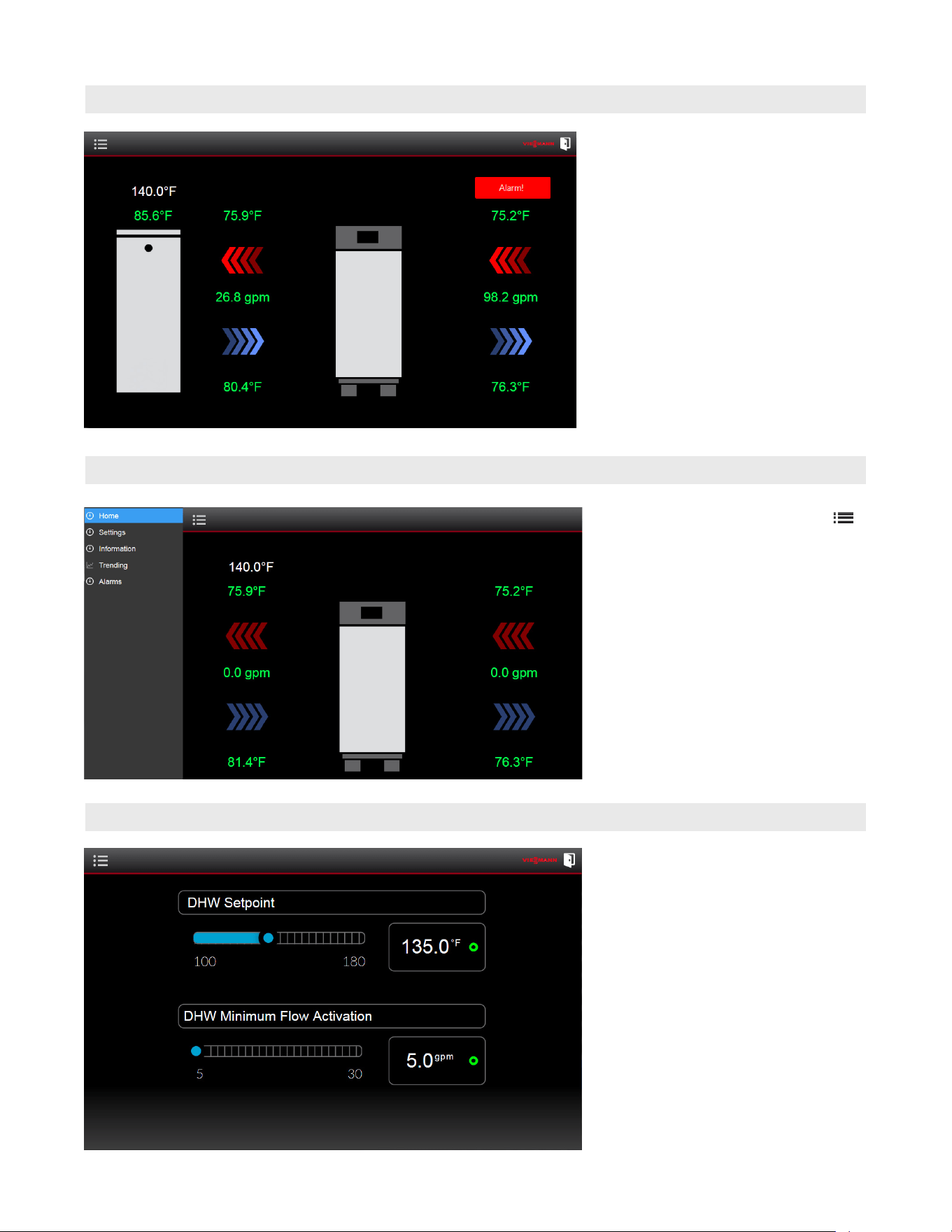
- If a fault has occurred, an “Alarm!” will
be displayed in the top right corner of
the screen. For detailed fault information
refer to page 49.
Operation
Fault Notification
From the home screen select menu .
The following items will be displayed:
- Home
- Settings
- Information
- Trending
- Alarms
User Interface Menu
DHW Setpoint – This is the setpoint
temperature of DHW supplied by the
Vitotrans 300 and is adjustable from
100ºF to 190ºF (38ºC to 88ºC).
This slider controls the DHW
temperature setpoint for the DHW
storage tank or direct DHW depending
on which mode of operation is selected.
DHW Minimum Flow Activation – This is
the minimum domestic water flow that is
required to activate the Vitotrans 300.
This can be set from 5 GPM to 30 GPM
(19 L/min. to 114 L/min.).
User Interface Settings
47
5833 275 - 07
Vitotrans 300 Installation, Operating and Service
Operation
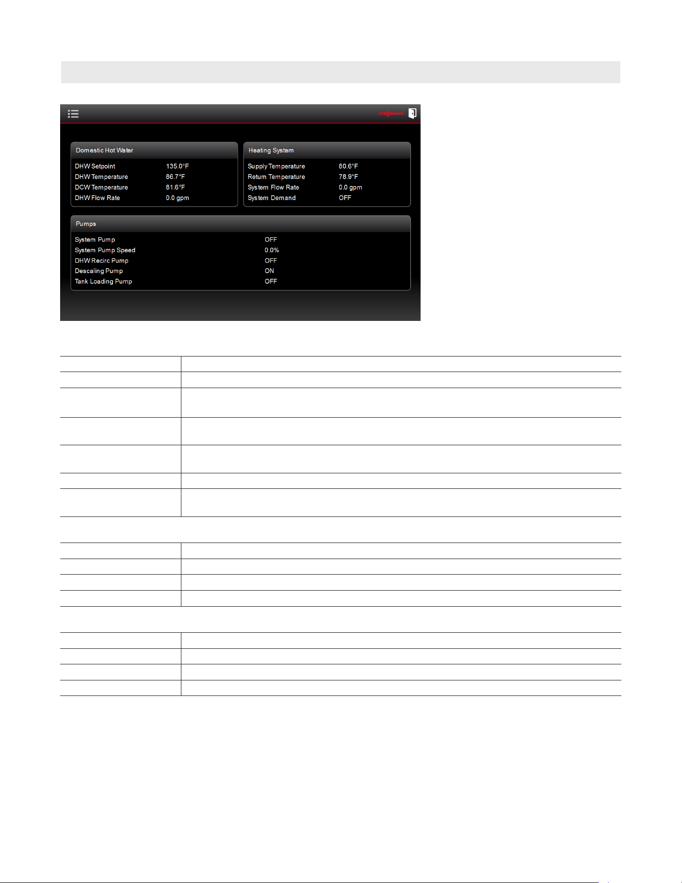
Information
Displays the current operating condition.
Pumps
System Pump A Operational status of main system pump A, will run anytime there is demand for DHW.
System Pump A Speed Modulating signal to pump A (20%-80%)
System Pump B
(S3HA/D3HA 90 only)
Operational status of main system pump B, may run in conjunction with pump A when
there is demand for DHW.
System Pump B Speed
(S3HA/D3HA 90 only)
Modulating signal to pump B (20%-80%)
DHW Recirculation Operational signal for DHW recirculation pump, will activate according to schedule
programmed by contractor.
Descaling Pump Operational status of descaling pump, will run continuously whenever the unit is in standby.
Tank Loading Pump Operational signal for DHW storage tank loading pump, will activate when there is a
demand to recover the DHW storage tank.
Domestic Hot Water
DHW Setpoint Domestic hot water setpoint temperature
DHW Temperature Dual sensor actual DHW temperature A
DCW Temperature Domestic cold water incoming temperature
DHW Flow Rate Actual domestic hot water draw rate
Heating System
Supply Temperature Actual heating system supply water temperature
Return Temperature Actual heating system return water temperature
System Flow Rate Actual heating system flow rate through the unit
System Demand Call for heat to the heating system
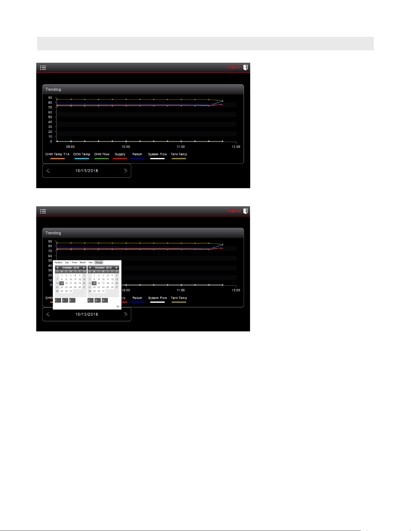
48
5833 275 - 07
Vitotrans 300 Installation, Operating and Service
Operation
This screen will display the historical data
points in 15-minute intervals over a 1-day
period.
The following historical trends will be
displayed on a vertical axis:
- DHW Supply Temp
- DCW Temp
- DHW Flow
- Supply
- Return
- System Flow
Trending
To view historical trending data, use the
arrows at the bottom left of the screen to
scroll between different dates.
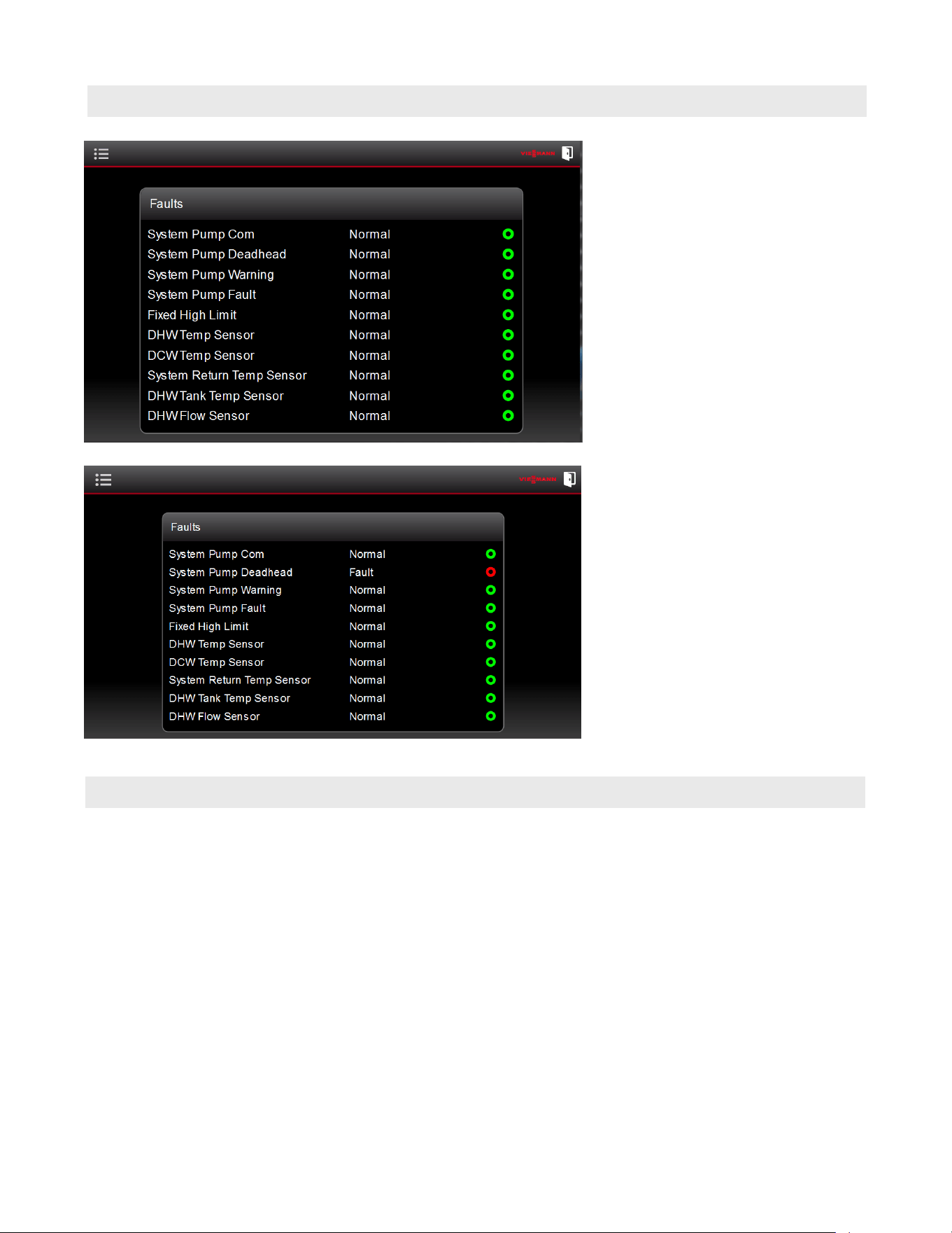
49
5833 275 - 07
Vitotrans 300 Installation, Operating and Service
Alarms
This screen will display the fault
or alarm status of the sensors and
components of the Vitotrans 300.
For service contact a heating
contractor.
The following are the possible faults
that may occur accompanied by a
status message):
- System Pump Communication
- System Pump Dead Head
- System Pump Warning
- System Pump Fault
- Fixed High Limit
- DHW Temperature Sensor
- DCW Temperature Sensor
- Return Temperature Sensor
- Tank Temperature Sensor
- Flow Sensor
The fault message is followed by an
indicator (‘Green’ indicates Normal and
‘Red’ indicated a Fault).
Operation
Shutting Down the System
Shut down your heating system completely if it will not
be needed for long periods (e.g. several months).
We recommend you contact your local heating contractor
if you are planning to take your heating system out of use
for long periods. Your heating contractor can then take
suitable steps such as frost protection for the system or
heating surface preservation as required.
1. Turn OFF the ON/OFF switch.
Note: The system is no longer protected against frost.
2. Close isolation valves.

50
5833 275 - 07
Vitotrans 300 Installation, Operating and Service
Issues System Characteristics Measures
The Vitotrans is off. Screen is blank after touch. Turn the Vitotrans ON.
Check main power supply breaker.
DHW is not hot enough. DHW temperature not as hot as
desired.
Check DHW setpoint and increase if necessary.
Check heating system function and supply
temperature, increase if necessary.
Check heating system valves and ensure they are
in open position.
Check heating system side strainer for debris and
flush if necessary.
Not enough DHW flow. DHW supply flow is insufficient
but the DHW meets desired
temperature
Check valves and ensure they are in open position.
Check DHW side strainer for debris and flush if
necessary. Heat exchangers may be blocked and
require cleaning or replacement.
DHW is too hot. DHW supply flow is not adequate
and warmer than desired.
Check DHW setpoint and decrease if necessary.
Check heating system function and supply
temperature, decrease if necessary.
Verify all temperature sensors are installed
correctly in wells.
Fault message displayed. Vitotrans may or may not be
operational.
Check fault message refer to page 60.
DHW storage tank is not hot
enough.
DHW storage tank does not
reach desired temperature.
Check DHW tank temperature setpoint and increase
if necessary.
Check heating system function and supply
temperature, increase if necessary.
Check tank loading pump function.
Check that the temperature sensor has been
installed correctly.
DHW storage tank is too
hot.
DHW storage tank is hotter than
desired.
Sanitation function may be enabled, contact your
heating contractor to verify settings.
Check DHW tank temperature setpoint and decrease
if necessary.
Check heating system function and supply
temperature, decrease if necessary.
Check that the tank temperature sensor is
functioning and has been installed correctly.
Note: Carry out measures in the described order.
Troubleshooting
Operation

51
5833 275 - 07
Vitotrans 300 Installation, Operating and Service
Safety Instructions
Service
Target group
These instructions are intended exclusively for qualified
contractors.
■ Work on gas installations must only be carried out
by a licensed professional heating contractor.
■ Work on electrical equipment must only be carried
out by a qualified electrician.
■ The system must be commissioned by the system
installer or a qualified person authorized by the installer.
■ This appliance has not been designed to be operated
by individuals other than those qualified and trained.
Regulations
Observe the following when working on this system:
■ Statutory regulations regarding the prevention of accidents
■ Statutory regulations regarding environmental protection
■ Codes of practice of the relevant trade associations.
Auxiliary components, spare and wearing parts
Note: Spare and wearing parts that have not been tested
together with the system can compromise its function.
Installing non-authorized components and making
non-approved modifications or conversions can
compromise safety and may invalidate our warranty.
For replacements, use only original spare parts
supplied or approved by Viessmann.
Note: Electronic assemblies can be damaged by
electrostatic discharges. Before beginning work,
touch grounded objects, such as heating or water
pipes, to discharge static loads.
Repair work
Note: Repairing components that fulfil a safety function
can compromise the safe operation of your system.
Replace faulty components only with original
Viessmann spare parts.
Working on the system
■ Where gas is used as the fuel, close the main gas
shut-off valve and safeguard it against unintentional
reopening.
■ Isolate the system from the power supply (e.g. at the
separate fuse or a main switch) and check that it is
de-energized.
■ Safeguard the system against reconnection.
Checking the high limit safety cut-out setting
The high limit safety cut-out is preset to 210°F (99°C).
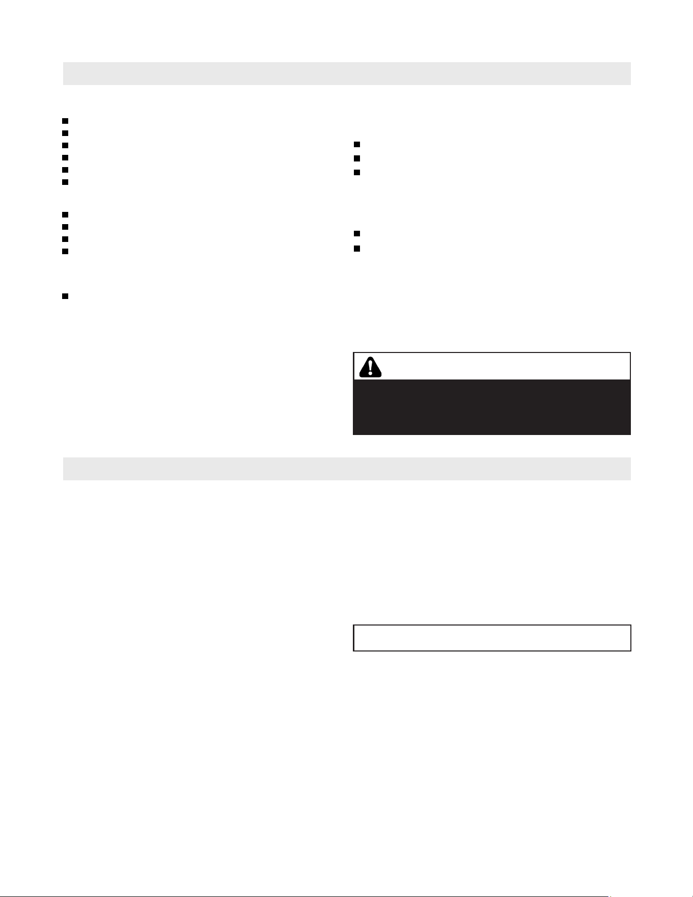
52
5833 275 - 07
Vitotrans 300 Installation, Operating and Service
Service Equipment
Service
Tools
Assortment of flathead and Phillips screwdrivers
Pipe wrenches
Open-ended wrenches
Pipe sealant
Assortment of Hex keys
Flashlight
Cleaning supplies
Plastic hand brush
Cleaning/service brush
Vacuum cleaner
Clean rags
Testing/analysis equipment
(use only calibrated equipment)
Multimeter to measure 0-120VAC, 0-25 amps AC
and 0-100 microamps DC.
Technical information
The following is a list of literature applicable to the
Vitotrans 300:
Installation, Operating and Service Instructions
Technical Data Manual
Wiring diagrams
For installation of the heating system, please refer also
to the technical literature of other Viessmann System
Technology devices:
Installation Instructions for accessories
Installation Instructions for Viessmann hot water
heating boilers
Replacement parts
For a complete listing of replacement components, please
see Parts List starting on page 75 of these instructions.
Order replacement components from your Viessmann
distributor.
CAUTION
Use only original Viessmann recommended components
when replacing defective parts. Installation of incorrect
replacement parts can cause hazardous operation and
will void warranty.
Service and Cleaning
IMPORTANT
Inspection and (if necessary) cleaning of unit must take
place within 2 years of initial start-up and as required
thereafter. Reinspection time must not exceed 2 years.
The internal cleaning of the Vitotrans including its potable
water connections may only be performed by a licensed
professional heating contractor. There are no user
serviceable parts on this equipment.
Clean the Vitotrans enclosure with a commercially
available alcohol-based glass cleaning agent and a soft
clean cloth.
If a water softener system is used in the domestic cold
water inlet piping into the Vitotrans, the water treatment
system should be inspected (serviced) at the same time.
If a drinking water filter is used in the main line, the
filter cartridge should also be investigated. All external
equipment must be serviced regularly and function
properly.
For water quality requirements refer to page 29.
For maintenance schedule refer to page 87.
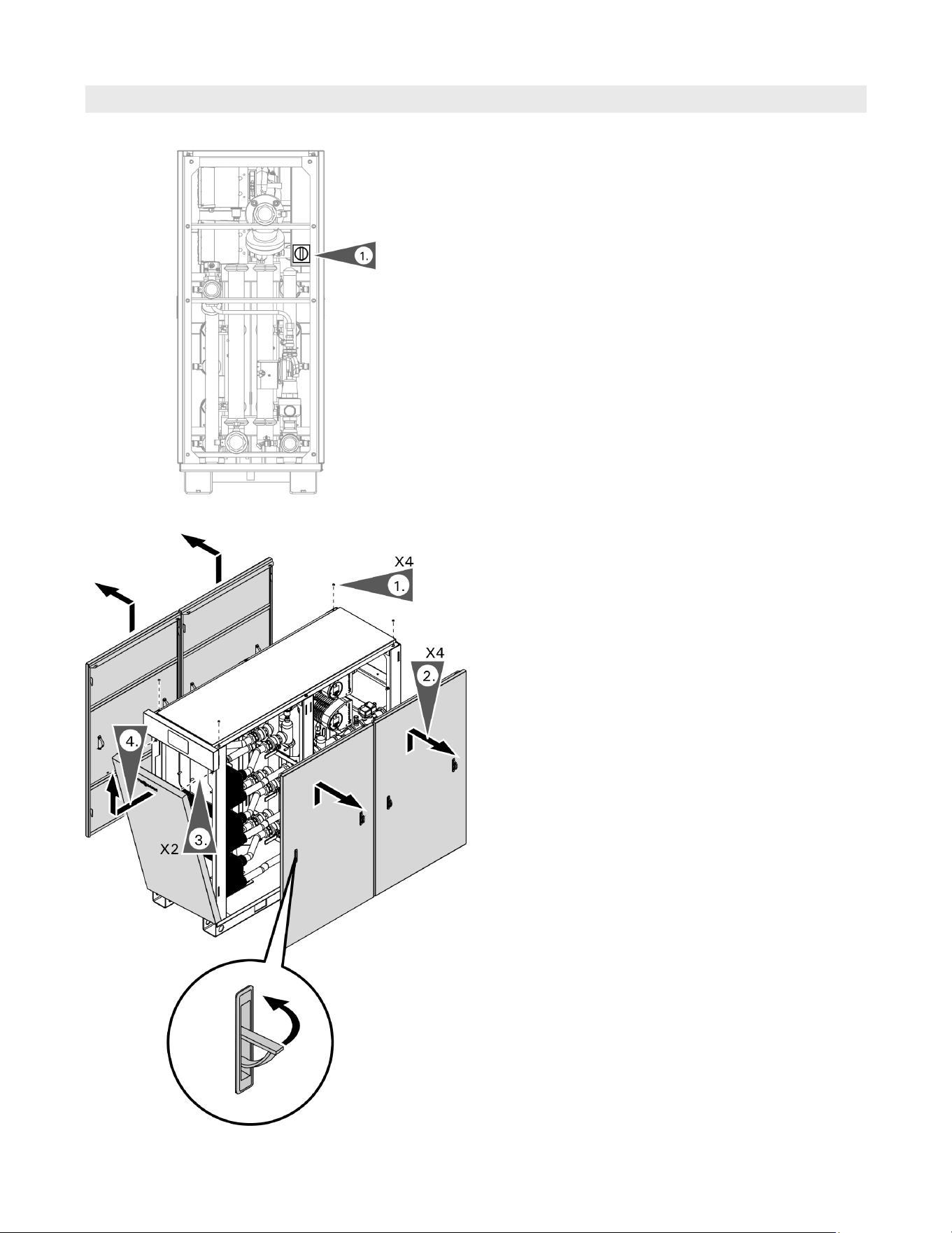
53
5833 275 - 07
Vitotrans 300 Installation, Operating and Service
Preparing for Service
Service
1. Remove the top locknuts.
2. Using handles lift and remove the side panels.
3. Remove front panel retaining screws.
4. Tilt forward, then lift and remove the front panel.
1. Turn the main power switch to the OFF position
(lockout provisions are provided on the switch).
Removing the panels
Power
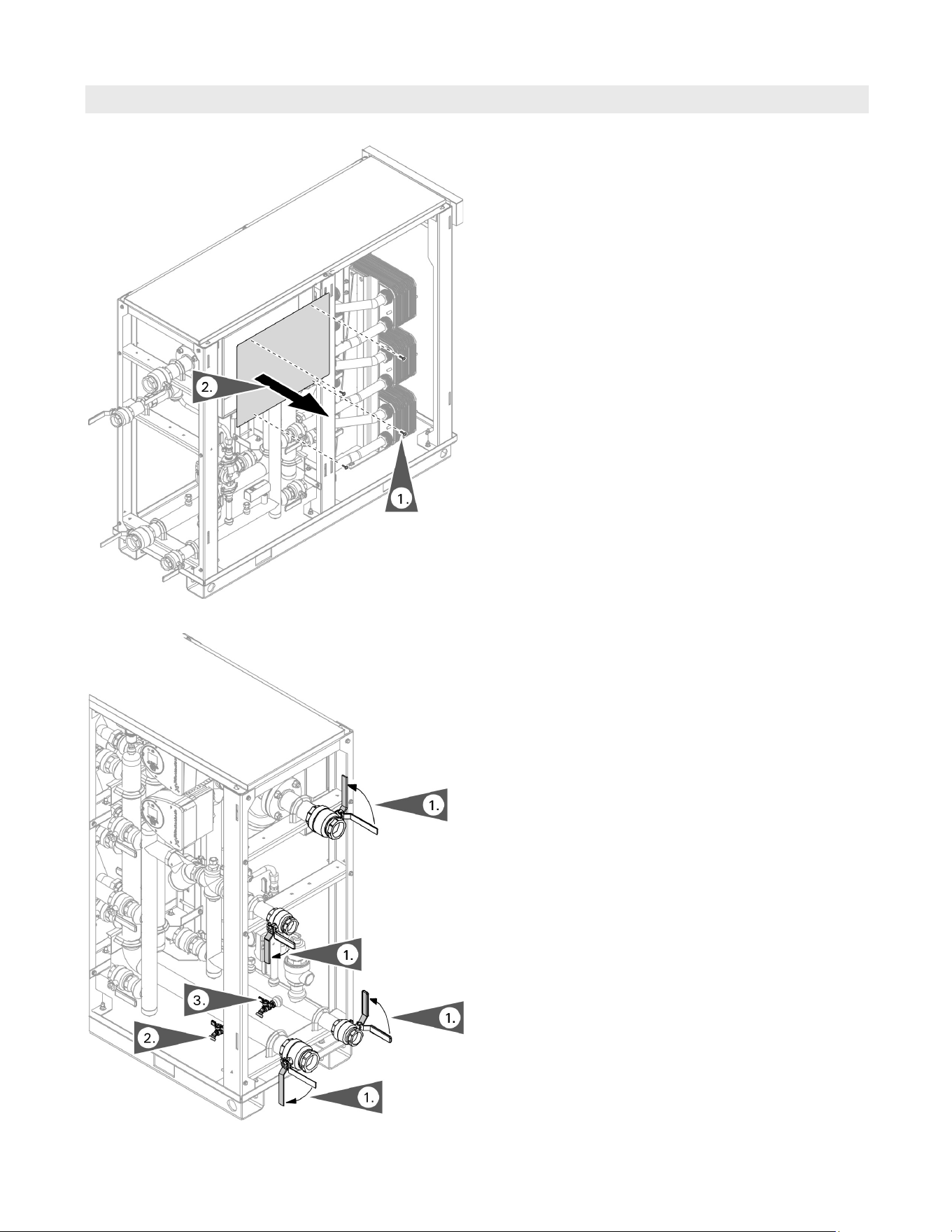
54
5833 275 - 07
Vitotrans 300 Installation, Operating and Service
Service
Preparing for Service (continued)
1. Remove junction box retaining screws.
2. Remove junction box cover panel.
Accessing the junction box
1. Turn the hydronic connection valves to the closed
position.
2. Connect a hose from the Vitotrans heating system
drain shutoff valve and route to a floor drain (when
servicing the heating system side). Open the valve.
3. Connect a hose from the Vitotrans DHW drain shutoff
valve to a floor drain (when servicing the DHW side).
Open the valve.
Isolating from system hydronics and draining the Vitotrans
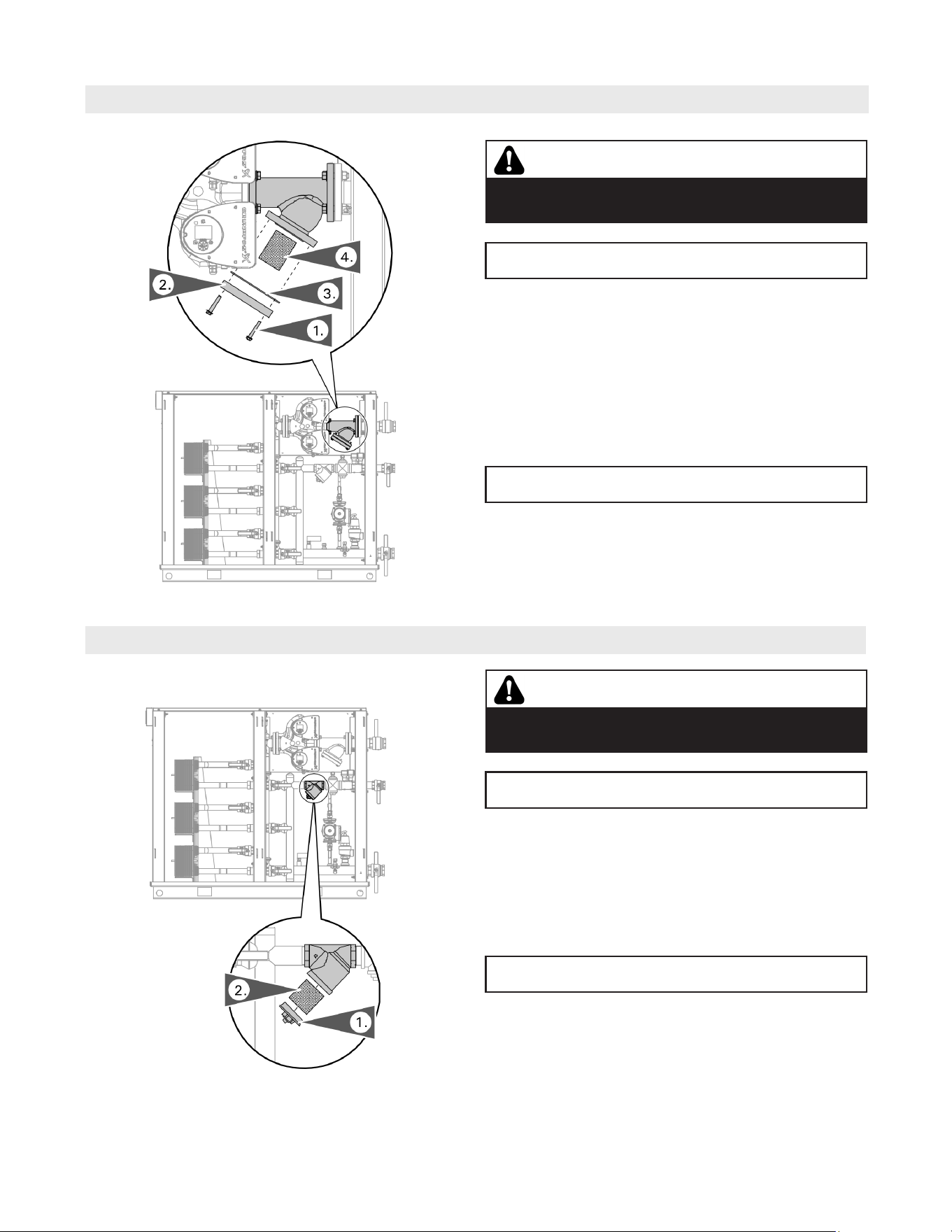
55
5833 275 - 07
Vitotrans 300 Installation, Operating and Service
Heating System WYE Strainer
1. Remove filter cap retaining bolts.
2. Remove filter retaining cap.
3. Remove filter retaining cap gasket.
4. Remove filter and rinse out any accumulated debris.
Inspect for damage and replace as necessary.
5. Reinstall in reverse order.
CAUTION
Hot surface, Do Not Touch.
Allow to cool before servicing.
IMPORTANT
See preparing for service starting on page 53.
Service
IMPORTANT
Refer to completion of service starting on page 65.
IMPORTANT
Refer to completion of service starting on page 65.
CAUTION
Hot surface, Do Not Touch.
Allow to cool before servicing.
IMPORTANT
See preparing for service starting on page 53.
1. Remove filter cap.
2. Remove filter and rinse out any accumulated debris.
Inspect for damage and replace as necessary.
3. Reinstall in reverse order.
Domestic WYE Strainer
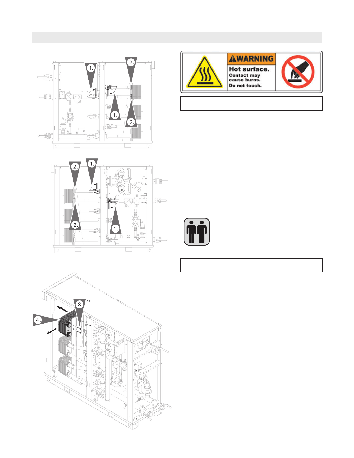
56
5833 275 - 07
Vitotrans 300 Installation, Operating and Service
Heat Exchangers
Service
It is recommended that two people
complete this work.
1. To isolate the heat exchanger, close the 4 isolation
valves for the heat exchanger being serviced.
2. Decouple the 4 flex pipes at the heat exchanger that
is being serviced.
3. Remove the 3 retaining nuts from the heat exchanger
support bracket.
4. Remove the heat exchanger.
IMPORTANT
Allow to cool before servicing. See preparing for service
starting on page 53.
Note: Check for visible leaks on the heat exchanger (double
wall only). If leakage is found, replace heat exchanger.
Note: To remove the heat exchanger follow steps 3 and 4.
5. Reinstall in reverse order. Torque: 15 lb.ft (20 Nm).
IMPORTANT
Refer to completion of service starting on page 65.
Note: Inspect each heat exchanger opening for flow
restrictions.
Note: The single wall heat exchanger weight is 53 lbs. (24 Kg)
The dual wall heat exchanger weight is 98 lbs. (44.6 Kg)
Cleaning the heat exchanger
The brazed plate heat exchangers operate with high
turbulence flow, even at low flow rates. This high turbulence
keeps small particles in suspension minimizing fouling and
scaling. In some applications the fouling can be very high
(e.g. when using extremely hard water at high temperatures).
It is always possible to clean the heat exchanger by
circulating a cleaning liquid. Use a weak acid, 5% phosphoric
acid or if the exchanger is frequently cleaned, 5% oxalic
acid. Pump the cleaning liquid through the exchanger. For
optimum cleaning, the cleaning solution flow rate should be
a minimum of 1.5 times the normal flow rate preferably in a
back-flush mode. After cleaning, rinse the heat exchanger
carefully with clean water and before the final rinse use
a solution of 1-2% sodium hydroxide (NaOH) or sodium
bicarbonate (NaHCO3) to ensure all acid is neutralized.
Clean at regular intervals.
Note: Only chemical cleaning is possible (use chemicals
which do not attack copper and stainless steel)
A commercial cleaning kit is available.
If in doubt, consult a cleaning specialist.
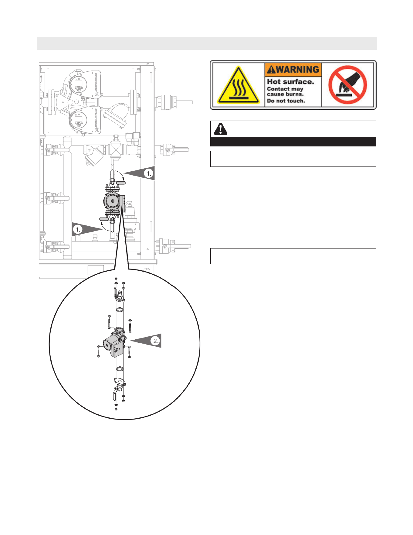
57
5833 275 - 07
Vitotrans 300 Installation, Operating and Service
Descaling Pump
Service
1. Isolate the descaling pump, by closing the 2 descaling
pump isolation valves.
2. Disconnect wiring to the pump (refer to the wiring
diagram). Remove the 4 pump bolts (remove the
top 2 first) and remove the pump.
3. Reinstall in reverse order.
IMPORTANT
Refer to completion of service starting on page 65.
WARNING
DISCONNECT POWER BEFORE SERVICING THE VITOTRANS.
IMPORTANT
Allow to cool before servicing. See preparing for service
starting on page 53.
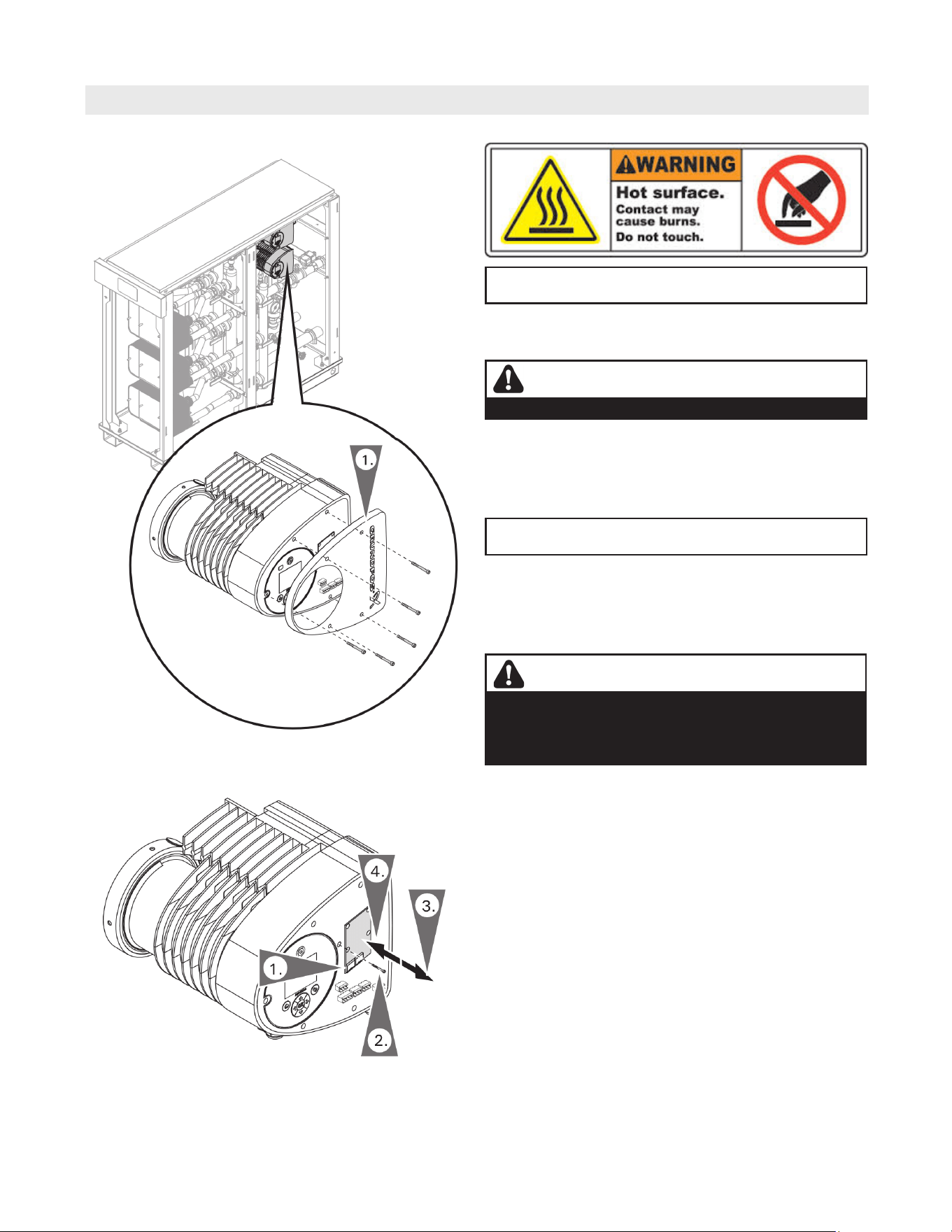
58
5833 275 - 07
Vitotrans 300 Installation, Operating and Service
System Pump
Service
1. On a dual pump system, locate the faulty pump.
and remove pump head cover.
IMPORTANT
Refer to completion of service starting on page 65.
Note: To determine the pump service procedure required,
see ‘System pump fault codes’ on page 61.
1. With the pump head cover off, disconnect cables from
the communication card.
2. Remove mounting screw.
3. Remove card by pulling straight out from the pump head.
4. Replace card, reconnect wires and pump head cover.
Replacing pump communication card
WARNING
DISCONNECT POWER BEFORE SERVICING THE VITOTRANS.
Note: The Vitotrans 300 is equipped with a variable speed
internal heating system pump, that has been
configured specifically for that Vitotrans 300 model.
WARNING
Do not attempt to alter the configuration of the internal
pump. In case of replacement, only use genuine
Viessmann replacemenrt parts. Failure to do so will
compromise the functionality of the Vitotrans 300.
IMPORTANT
Allow to cool before servicing. See preparing for service
starting on page 53.
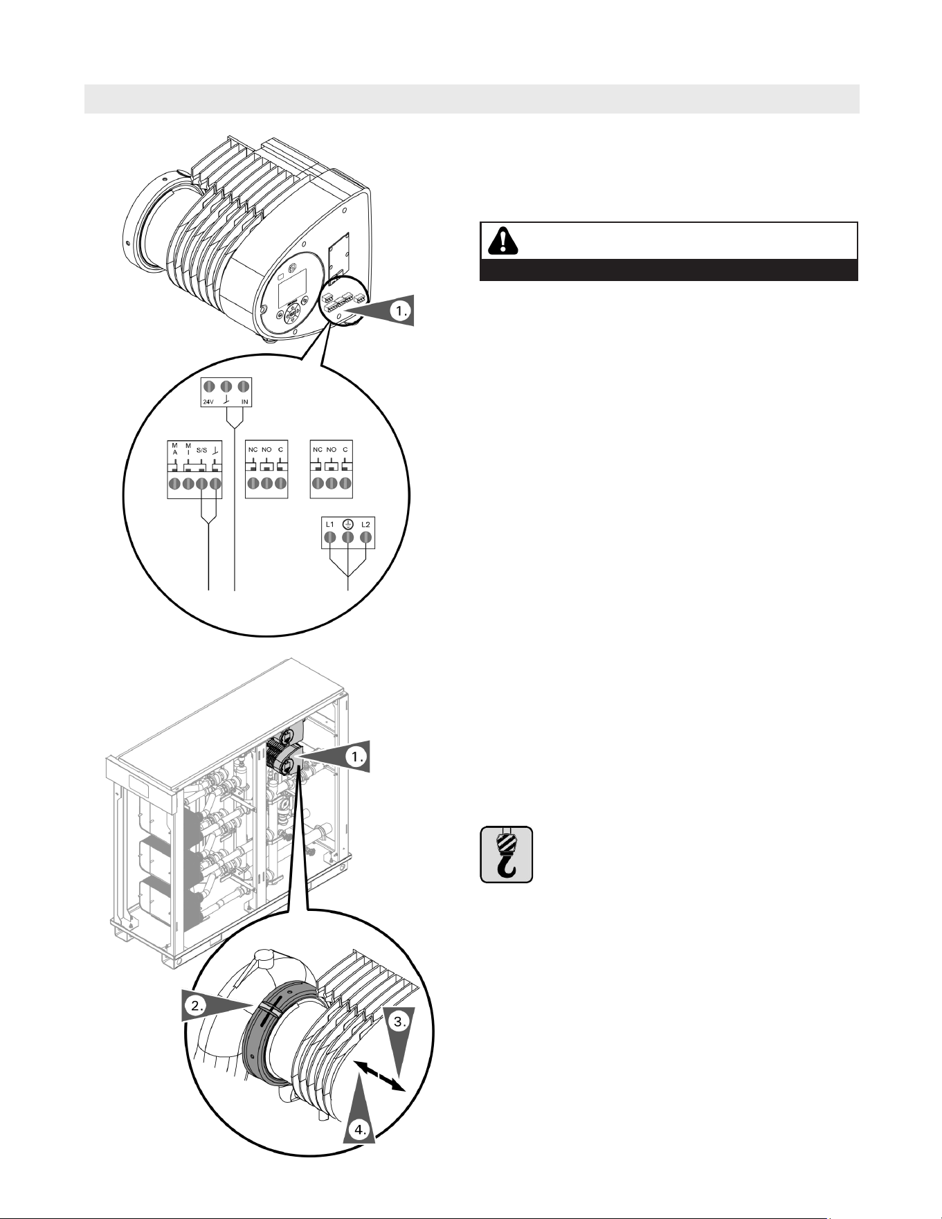
59
5833 275 - 07
Vitotrans 300 Installation, Operating and Service
System Pump (continued)
Service
1. With the pump head cover off, check all pump wiring
connections.
2. Correct faulty wiring.
3. Replace pump head cover.
Check pump wiring
Wiring to Control
All wiring is routed back to the main control, refer to
the wiring diagram on pages 71 and 72 for internal
connections.
1. With the pump head cover off, disconnect the wiring.
2. Support pump head and release the pump head collar.
3. Remove pump head by pulling the pump head straight
out from the pump body.
4. Replace the pump head, tighten collar and reconnect
the wiring.
Pump head removal
It is essential to use appropriate lifting devices
certified for lifting to a minimum of the pump
weight.
WARNING
DISCONNECT POWER BEFORE SERVICING THE VITOTRANS.

60
5833 275 - 07
Vitotrans 300 Installation, Operating and Service
Service
System Faults
System Fault
Display
System Characteristics Cause Measures
Temp Sensor
T1A/B Fault
Vitotrans is not producing DHW.
System pump will not run.
No boiler demand signal available.
Lead break or faulty sensor
T1A/B.
Check sensor wiring connections
and sensor.
Replace sensor if necessary.
Pump P1
Dead Head
Fault
Vitotrans is not producing DHW.
System pump will remain powered
but will not run.
No boiler demand signal available.
System pump P1 has experienced
excessive head pressure and is
not able to provide flow.
Check internal isolation valves
to ensure they are open.
Safety High
Limit
Vitotrans is not producing DHW.
System pump will no longer be
powered.
No boiler demand signal available.
The DHW supply temperature has
exceeded the setting of the fixed
high limit.
Wait for the DHW to cool.
Reset the fixed high limit.
Flow Sensor
Fault
Vitotrans will not respond to
demand for DHW.
No flow of domestic water.
Faulty sensor.
Verify domestic water flow
through unit.
Check sensor power supply.
Check for signal.
Refer to page 63.
Replace sensor if required.
Temp Sensor
T2 Fault
Vitotrans will continue normal
operation, DCW temperature
displayed as “0ºF”.
Lead break or faulty sensor T2. Check leads and sensor, replace
if required.
Temp Sensor
T4 Fault
Vitotrans will continue normal
operation, system return
temperature displayed as “0ºF”.
Lead break or faulty sensor T4. Check leads and sensor, replace
if required.
Temp Sensor
T5 Fault
Vitotrans will continue normal
operation, DHW storage tank
temperature displayed as “0ºF”.
Lead break or faulty sensor T5. Check leads and sensor, replace
if required.
System faults are displayed on the touch screen user
interface.
Note: Carry out measures in the described order.
All system faults are saved to the fault memory.

61
5833 275 - 07
Vitotrans 300 Installation, Operating and Service
Service
System Pump Warnings Codes
Pump Code
Display
System Characteristics Cause Measures
77
(S3HA/D3HA
-90 only)
Communication fault,
twin-head pump.
Communication between
pump heads disrupted or
broken.
Check that the pump heads are powered. One
pump head will display a yellow light and the
second pump head no light will be displayed.
88
Internal sensor fault. The pump is receiving a
signal from the internal
sensor which is outside
the normal range.
Replace the pump head.
93
External sensor fault. The pump is receiving a
signal from the external
control signal which is
outside the normal range.
Does the electrical signal set (0-10VDC) match
the control’s output signal? Refer to page 69.
If the control’s output signal does not match
replace the control PLC.
If the control’s output signal, does match replace
the pump head.
System pump warnings are displayed on the touch screen
user interface as a ‘Pump P1 Warning’. System pump (P1)
warning codes are displayed at the system pump. System
pump may continue to run, but will display a yellow
indicator light.
Remove right rear side panel to access the system pump.
Pump Code
Display
System Characteristics Cause Measures
10 Pump communication
fault.
Internal pump
communication fault.
Replace the pump head.
See code (29) Forced pumping.
29 Forced pumping. Other pumps or sources
forcing flow through the
pump even if the pump
is stopped and switched
off.
Check the system for correct position and / or
defective check valves and replace, if necessary.
40, 75 Undervoltage. Supply voltage to the
pump too low.
Check that the power supply is within the
specified range.
51 Blocked pump. The pump is blocked. Remove pump head and remove any foreign
matter or impurities preventing the pump from
rotating.
57 Dry running. No water at the pump
inlet or the water
contains too much air.
Prime and vent the pump before a new start-up.
Check that the pump is operating correctly. If not,
replace the pump head.
64 High motor
temperature.
Temperature in stator
windings too high.
Replace the pump head.
72, 84,
155, 157
Internal fault. Internal fault in the pump
electronics.
Replace the pump head.
74 Overvoltage Supply voltage to the
pump too high.
Check that the power supply is within the
specified range.
Note: Carry out measures in the described order.
‘Pump P1 Warning’ is saved to the fault memory.
System pump faults are displayed on the touch screen user
interface as a ‘Pump P1 Fault’. System pump (P1) fault
codes are displayed at the system pump. System pump will
not operate and will display a red indicator light.
Remove right rear side panel to access the system pump.
Note: Carry out measures in the described order.
‘Pump P1 Fault’ is saved to the fault memory.
System Pump Fault Codes
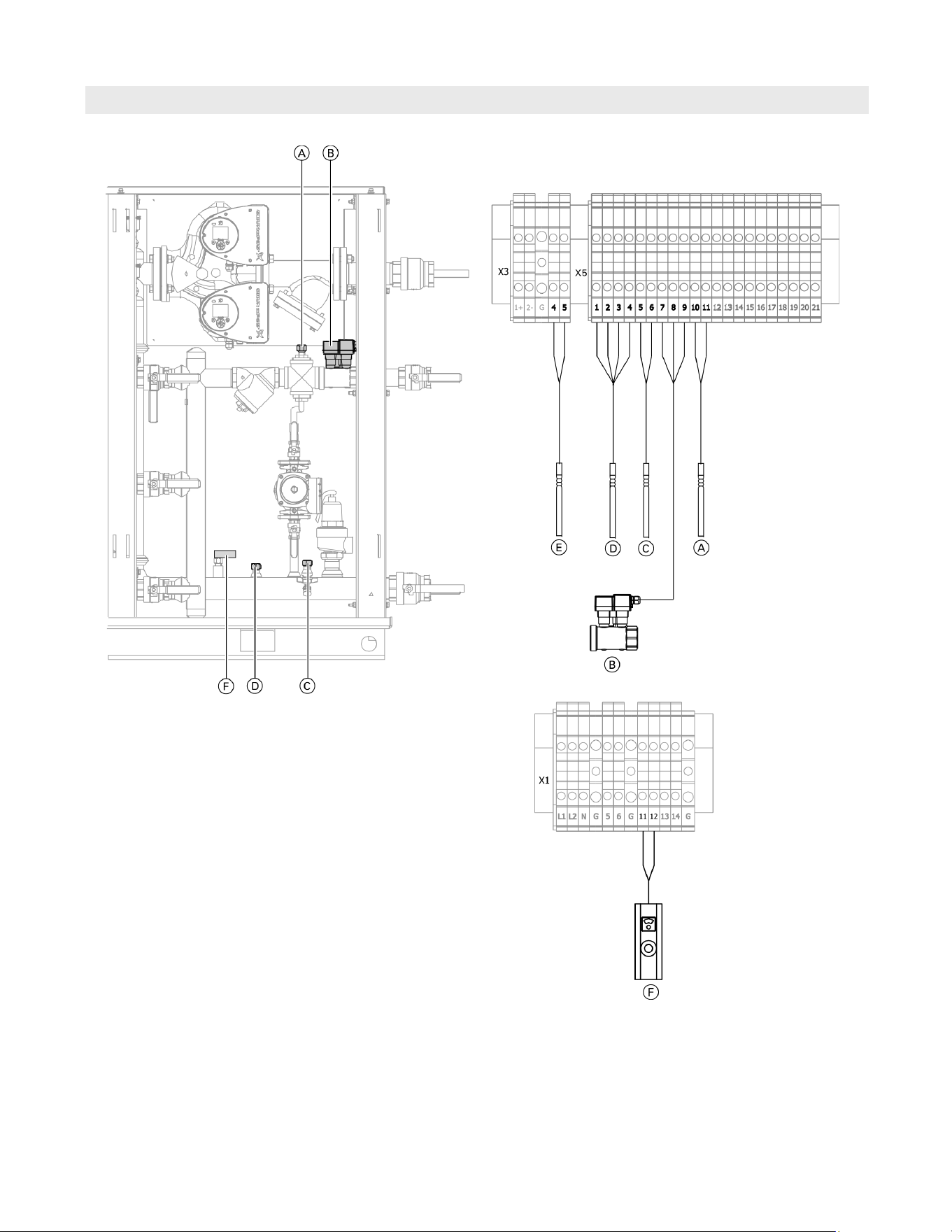
62
5833 275 - 07
Vitotrans 300 Installation, Operating and Service
Service
Sensors and FHL Location
Legend
A DCW temperature sensor (T2)
B Flow sensor
C System return temperature sensor (T4)
D DHW temperature sensor (T1A/B)
E DHW storage tank temperature sensor (T5)
(when optional DHW storage tank is used)
F Fixed high limit
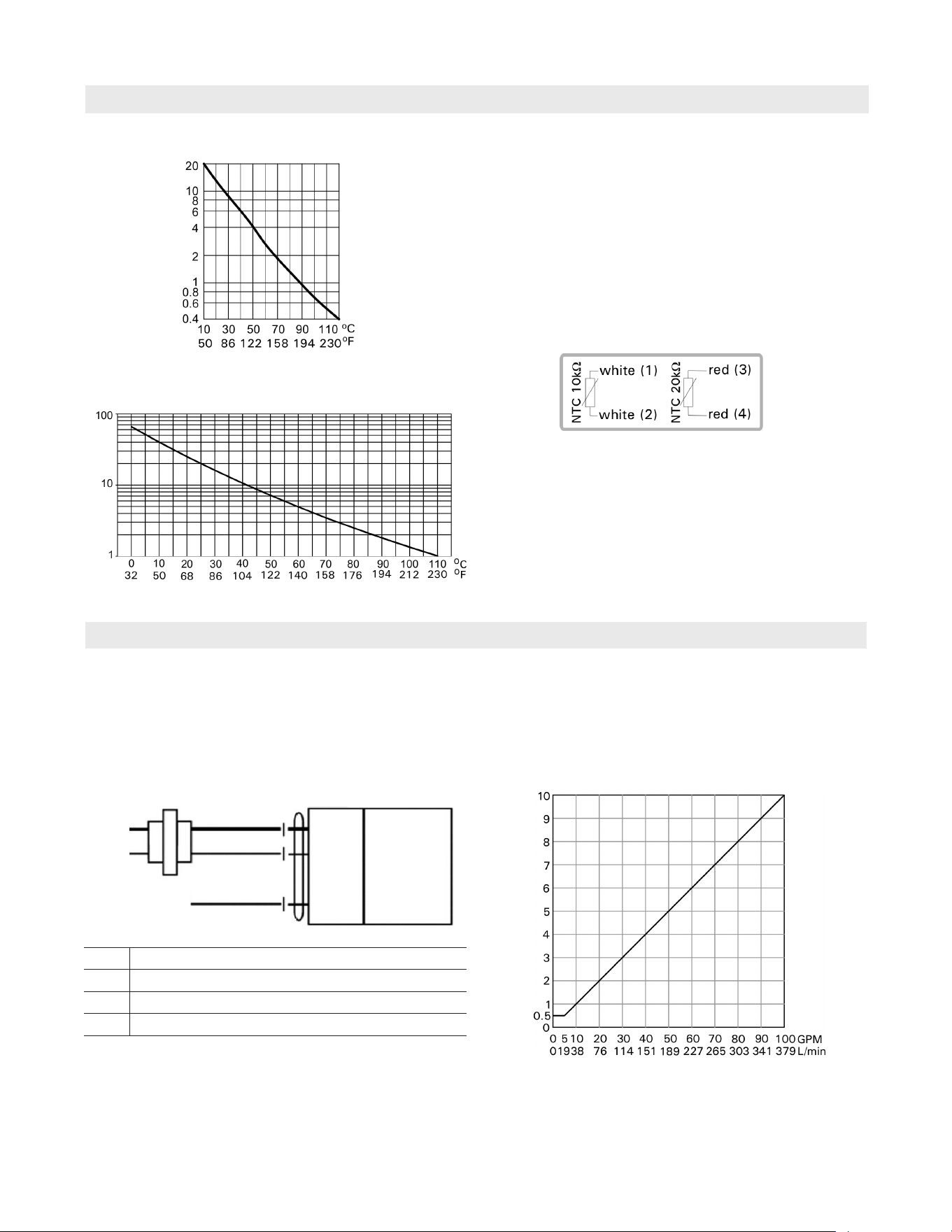
63
5833 275 - 07
Vitotrans 300 Installation, Operating and Service
Service
Temperature Sensors
Temperature
Resistance in k ohms
Temperature
Resistance in k ohms
Temperature sensor (NTC 10kW)
Temperature sensor (NTC 20kW)
1. Locate the sensor in the junction box and remove leads.
2. Check the sensor resistance and compare it with the
curve.
3. In the case of severe deviation, check the installation
and replace the sensor if required.
Flow Sensor
Blk (1)
Red (2)
Wht (3)
Line
Volts
0-10V DC
Common
Hot +
U Output
24V AC/DC Transformer
Operation
The ultrasonic flow meter is an accurate repeatable
liquid flow measurement meter by utilizing ultrasonic
transit time technology. The transducers perform as
both emitter and receiver to provide accurate signal
reflection.
0V Sensor has no supply voltage
0.3V Sensor has supply voltage but is in error state
0.5V Zero flow
10V Maximum flow
DHW temperature sensor
The DHW temperature sensor is a dual core NTC 10K /
NTC 20K sensor.
The boiler return temperature sensor
- single core NTC 10K sensor.
The DCW temperature sensor
- single core NTC 10K sensor.
The DHW storage tank temperature sensor
- single core NTC 10K sensor.
1. Locate the sensor in the junction box and remove leads.
2. Check the sensor voltage (0-10VDC) signal.
3. In the case of severe deviation, check the installation
and replace the sensor if required.
DC Voltage
Flow
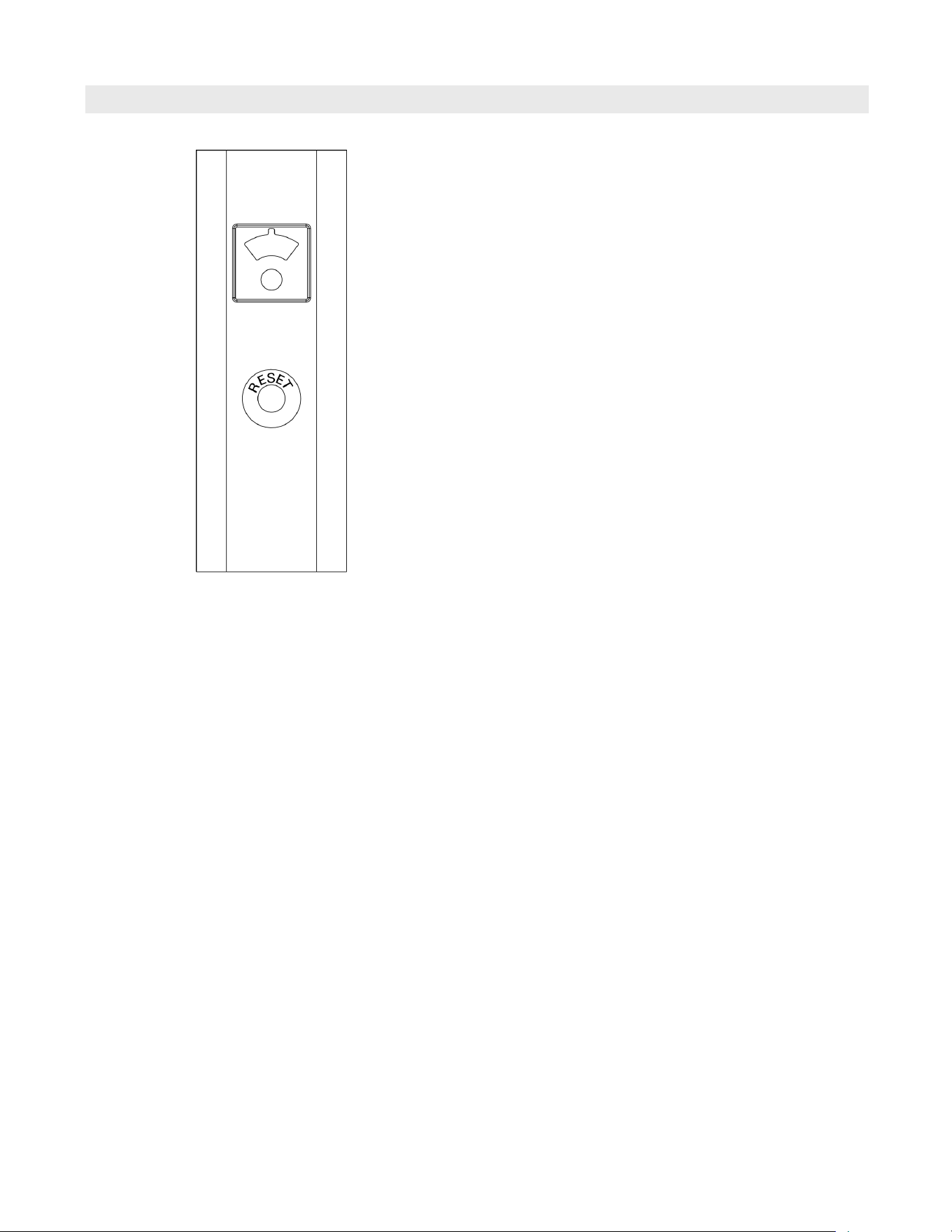
64
5833 275 - 07
Vitotrans 300 Installation, Operating and Service
Fixed High Limit
Operation
The limit switch is factory preset to 210ºF (99ºC)
Shuts off pump when DHW temperature exceeds high
limit setting. The pump will not restart until the
temperature drops to the high limit setting minus the
temperature differential, and the manual reset switch
is reset.
Manual reset
Press the red reset button on the front of the case
to make sure that the controller is not locked out on
safety. When checking out the system, adjust the
control point low enough so the temperature of the
controlled DHW reaches the high limit setting, the
system pump off and the Vitotrans controller locks out.
When the temperature of the DHW drops to the high
limit setting minus the differential, push the manual
reset button and the system should be operative again.
Reset the control to the proper high limit setting.
Service
1. Locate the fixed high limit connection in the junction box.
2. Check the installation and check the voltage at each
terminal.
3. In the case of no voltage, replace the fixed high limit.
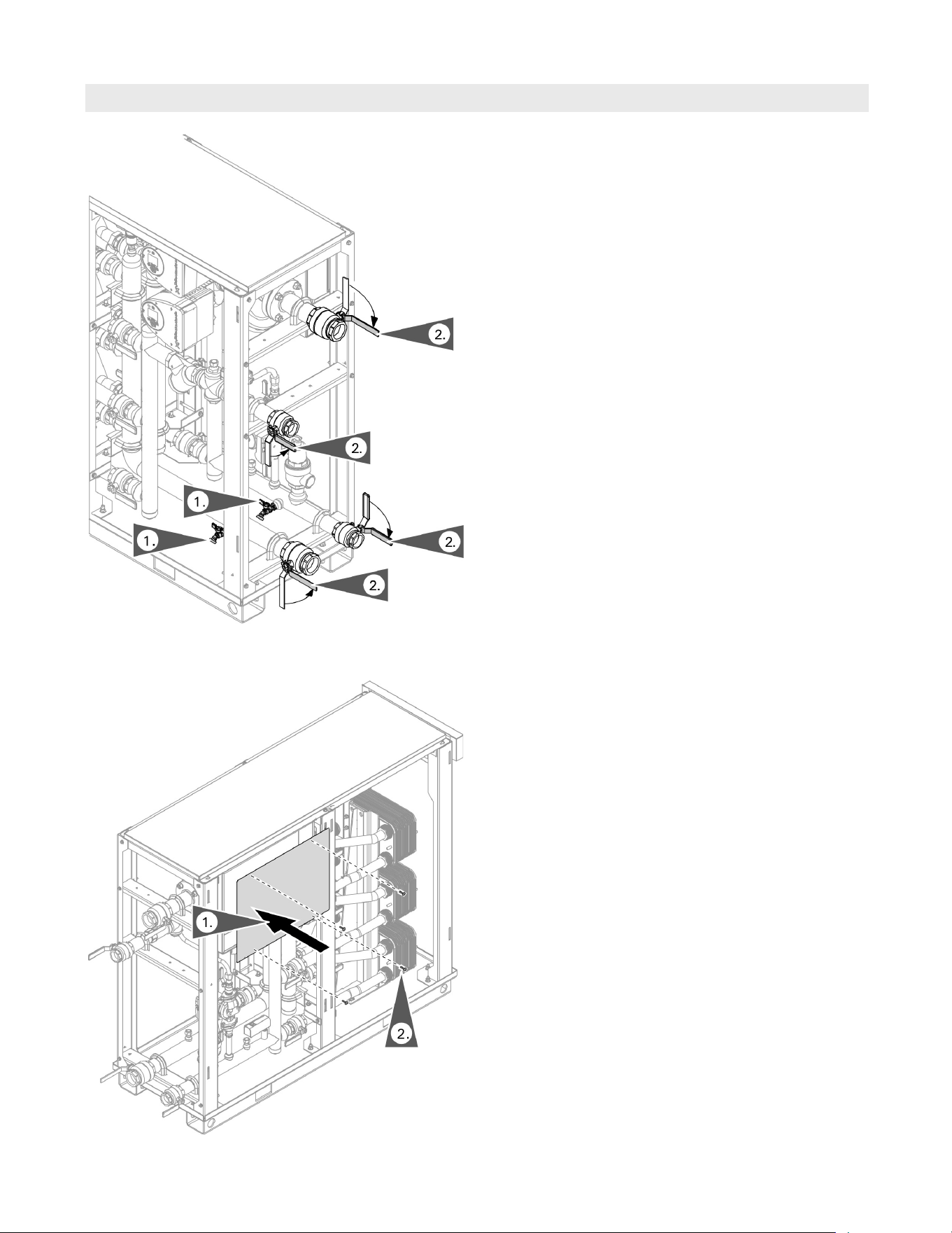
65
5833 275 - 07
Vitotrans 300 Installation, Operating and Service
Service
Completion of Service
1. Install the junction box cover panel with retaining
screws.
1. Close drain valve and remove drain hose.
2. Turn the hydronic connection valves to the open
position.
3. Check for leaks and correct any leaks before proceeding.
Reinstalling the junction box cover
Close drain valves and open system hydronic valves
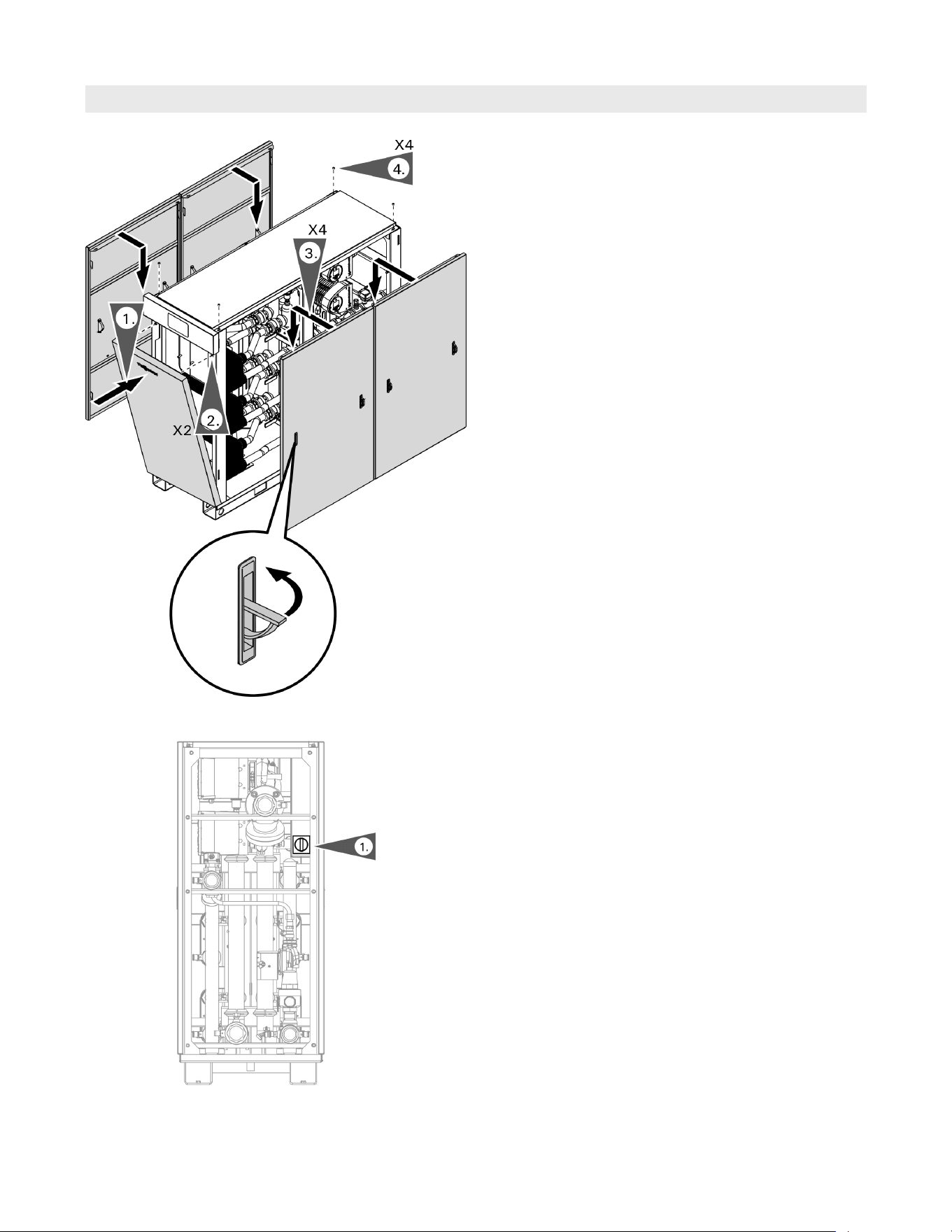
66
5833 275 - 07
Vitotrans 300 Installation, Operating and Service
Completion of Service (continued)
Service
1. Insert the bottom of the lower front panel in place
and push to close.
2. Secure with retaining screws.
3. Using handles lift and install the side panels.
4. Secure with retaining screws.
1. Turn the main power switch to the ON position.
Reinstalling the panels
Power
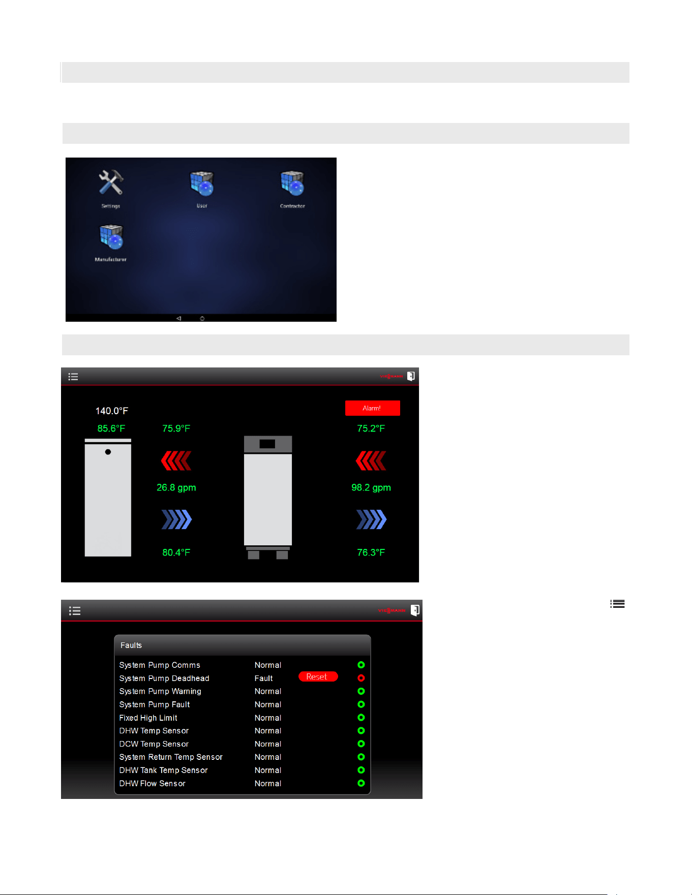
67
5833 275 - 07
Vitotrans 300 Installation, Operating and Service
Accessing Control for Contractor Service Levels
Service
User Interface
Putting the Unit into Operation After Service
Turn main power on using the switch located on the
rear of the Vitotrans 300.
From the home screen select menu .
From the menu select Alarms + to
switch to the ‘Faults’ screen.
This screen will display the fault or alarm
status of the Vitotrans 300’s sensors
and components. The fault message is
followed by an indicator on the far right
of the screen (‘Green’ indicates Normal
and ‘Red’ indicated a Fault).
Faults
If a fault has occurred, an “Alarm!” will be
displayed in the top right corner of the
home screen. For detailed fault information
refer to page 60.
The following faults will shut down the
system until the fault is corrected and
the Reset button is selected:
- System Pump Communication
- System Pump Dead Head
- System Pump Warning
- System Pump Fault
- Fixed High Limit
Log into the system by tapping the icon for the desired
level of system access, no password is required for user
level access. Service level access is password protected;
Service level password: viservice
To switch access levels, tap the circle icon located at
the bottom of the screen to return to login screen.
The setting icon on the home screen is for adjustment
of the screen settings only – do not adjust.
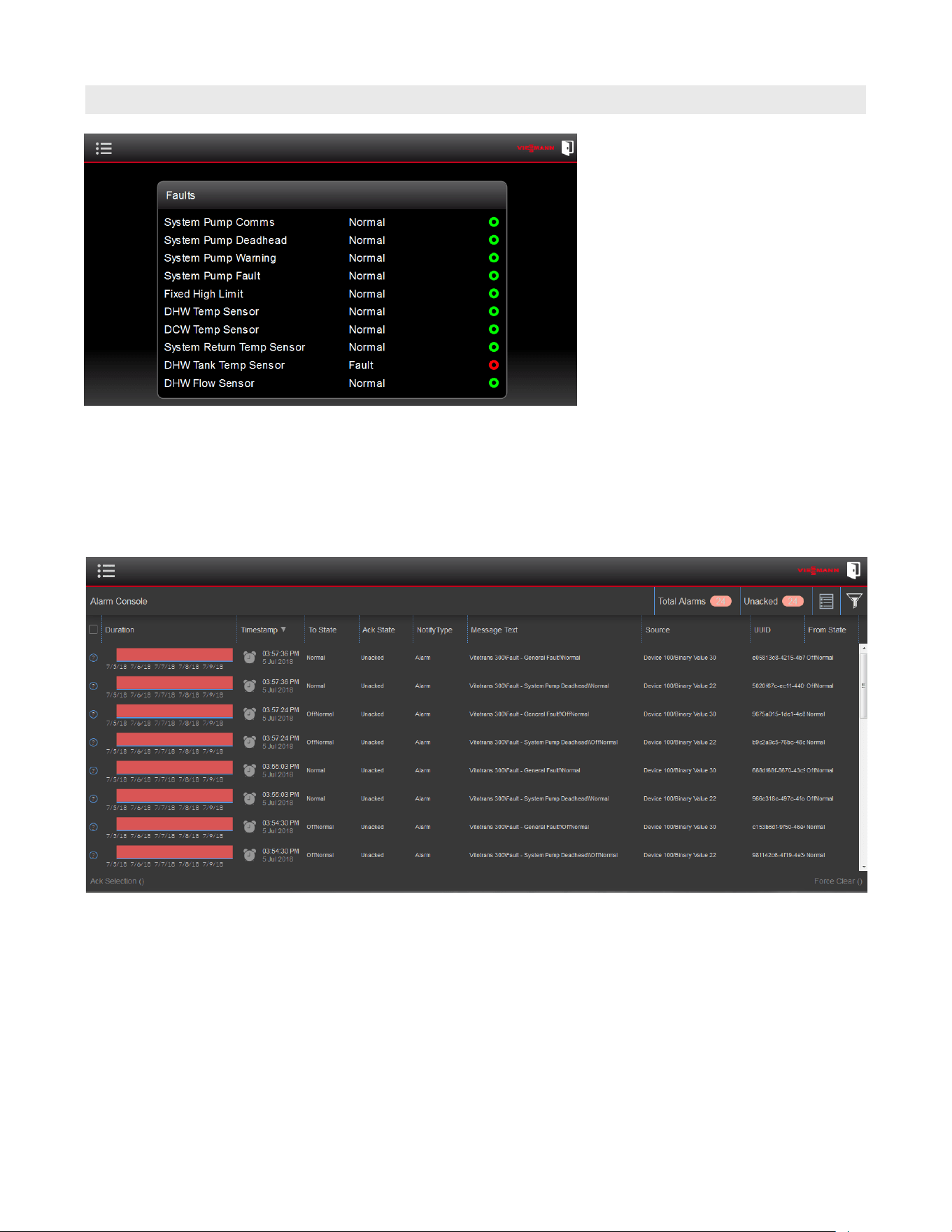
68
5833 275 - 07
Vitotrans 300 Installation, Operating and Service
Fault History
Service
Press the Alarm History button on the menu pane to
display an ongoing history of previous faults.
Note: Alarms/Faults cannot be reset or cleared from
this screen. Any fault that occurs is displayed
as well as accompanied by a ‘General Fault’.
The following faults will allow the system
to continue to operate and when the fault
is corrected the fault will automatically
reset:
- DHW Temperature Sensor
- DCW Temperature Sensor
- Return Temperature Sensor
- Tank Temperature Sensor
- Flow Sensor
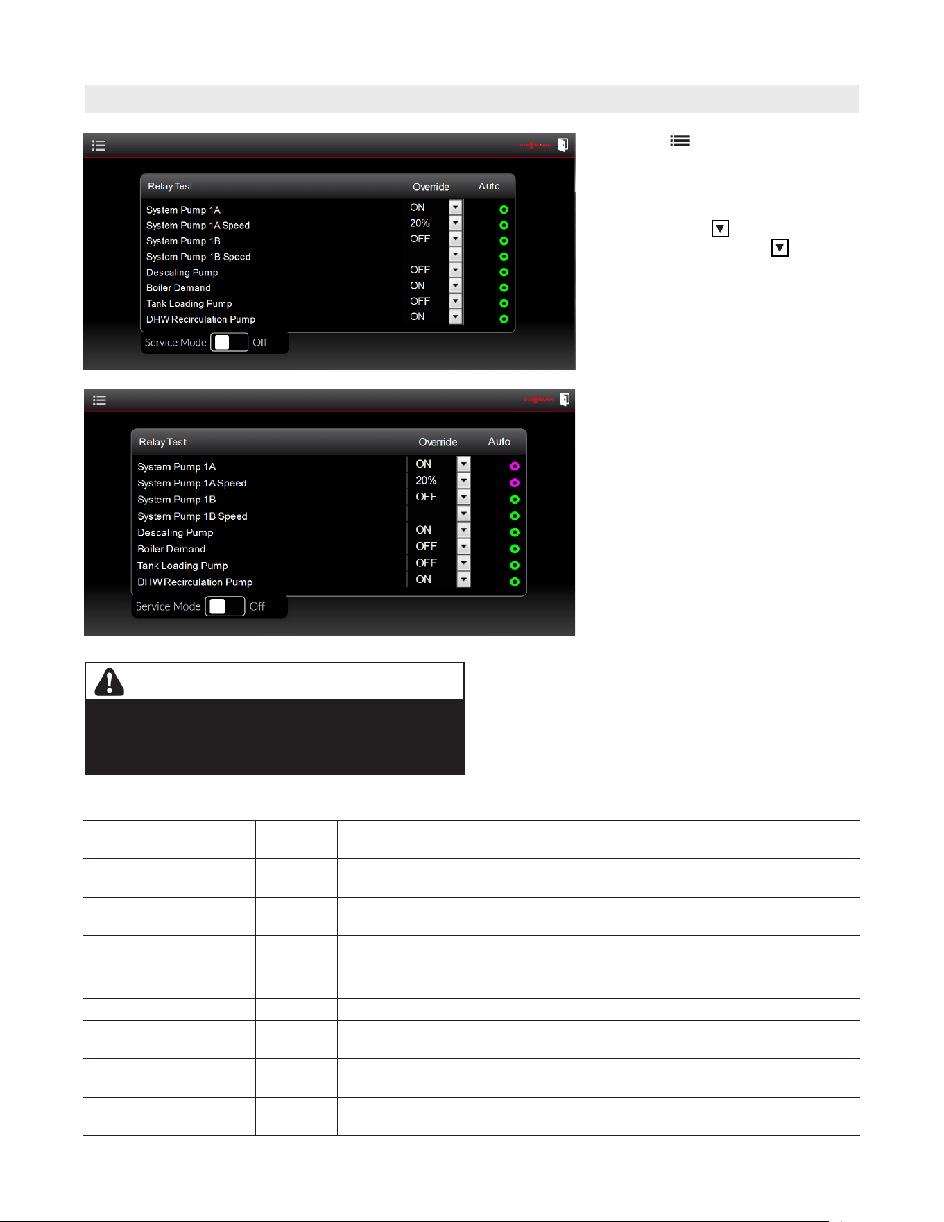
69
5833 275 - 07
Vitotrans 300 Installation, Operating and Service
Select menu . then press the
Maintenance button to allow access to
testing and service functions.
To activate the ‘override’ (to test the
outputs) select the button of the
desired output. Pressing the
will
provide access to the ‘Override’ options,
select the desired function.
The ‘Auto’ indicator will switch from
‘green’ to ‘purple’ (indicating that
function is in the override mode).
When relay testing is complete, select
the ‘purple’ indicator. This will return the
‘Auto’ indicator to green.
Failure to return the ‘Auto’ indicator
to
green may cause undesired performance
and/or function(s).
Maintenance Mode / Relay Test
Service
WARNING
Enabling System Demand without adequate flow through
the heating system or boiler may be unsafe. Ensure there is
sufficient flow through the heating system or boiler before
testing System Demand.
The following outputs can be tested and will operate as such:
System Pump 1A ON or OFF This will turn the primary system pump ON or OFF. When turned ON, the
pump will run at its lowest speed.
System Pump 1A Speed 20 or 80% Once the primary system pump has been turned ON, this will enable the speed
to be manually adjusted to either 20% or 80% modulation.
System Pump 1B ON or OFF (S3HA/D3HA 90 only) This will turn the secondary system pump ON or OFF.
When turned ON, the pump will run at its lowest speed.
System Pump 1B Speed 20 or 80% (S3HA/D3HA 90 only) Once the secondary system pump has been turned ON,
this will enable the speed to be manually adjusted to either 20% or 80%
modulation.
Descaling Pump ON or OFF This will turn the internal descaling pump ON or OFF.
Boiler Demand ON or OFF This will turn the relay (dry contact) for the system or boiler call for heat ON
or OFF.
Tank Loading Pump ON or OFF This will turn the relay (dry contact) that controls the external tank loading
pump ON or OFF (if installed).
DHW Recirculation
Pump
ON or OFF This will turn the relay (dry contact) that controls the DHW recirculation pump
ON or OFF (if installed).
Outputs are based on Vitotrans 300 model and system configuration.
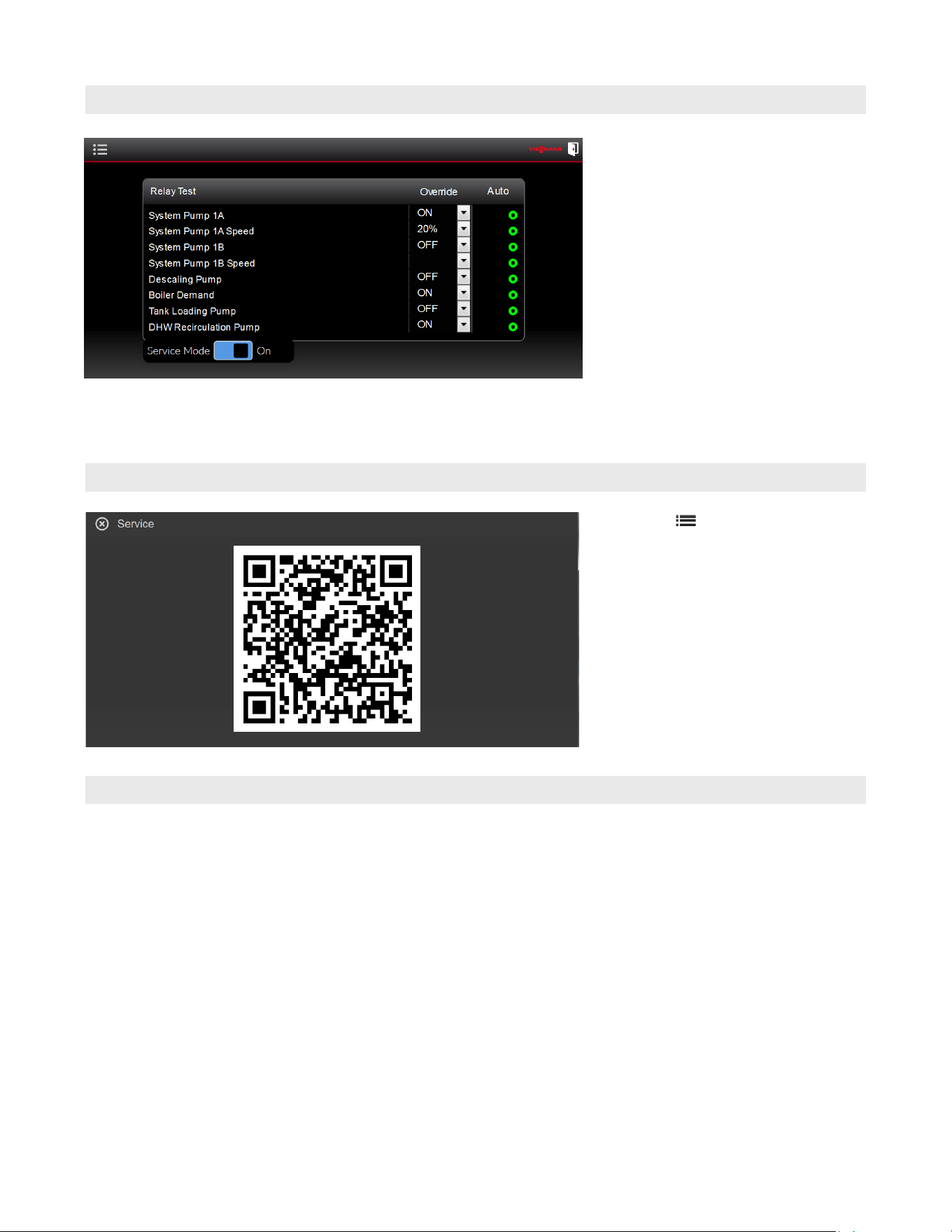
70
5833 275 - 07
Vitotrans 300 Installation, Operating and Service
Maintenance Mode
Service
Service Mode - (S3HA/D3HA 60 & 90
only) Turn on the ‘Service Mode’ slide the
switch to the on position. This function
allows reduced operation the Vitotrans
300 while being serviced so that DHW
production can continue uninterrupted.
The heat exchangers can be isolated and
removed one at a time for cleaning or
serviced (see page 56) and the Vitotrans
300 will continue to operate with a
reduced capacity using the remaining heat
exchanger(s).
The Service Mode function does not have
an automatic time out, turn the Service
Mode switch to the“Off” position.
Note: this function is not available on the
S3HA/D3HA 30 models.
Select menu . then press the Service
button to display the service window.
A QR code will appear. Scanning the QR
code will bring all current documents for
the Vitotrans 300.
When finished with the QR code, press the
“X” in the top left corner of the screen to
close the service window.
When service work is complete in the CONTRACTOR
access level, log out to prevent unwanted changes
being made. This is done by pressing the “Door”
8
icon in the top right corner of the screen. A window
will pop up and prompt: “Do you want to leave this
site?” Press “Leave”.
To complete service log in as ‘user’. For user log In see
page 45.
Restoring to Normal Operation
Service
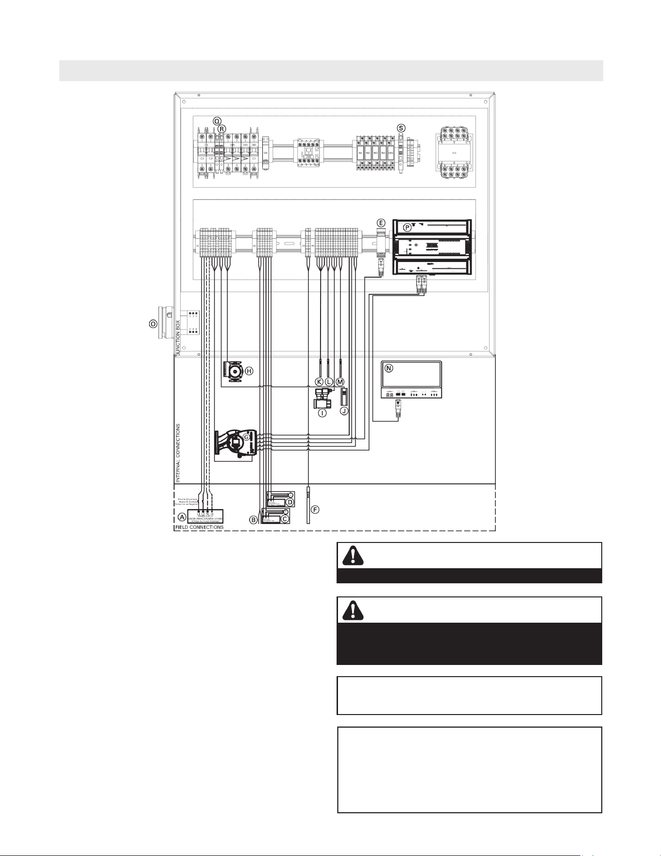
71
5833 275 - 07
Vitotrans 300 Installation, Operating and Service
Wiring Diagram - S3HA 30, D3HA 30, S3HA 60 and D3HA 60
Wiring
Legend
A Power supply 120/208-240VAC/1Ph/60 Hz L1/L2/N/G
B Boiler demand (dry contact)
C Building DHW re-circulation pump (dry contact)
D DHW storage tank (dry contact)
E BACnet (IP) communication RJ45
F DHW storage tank temperature sensor
G Heating system pump
H Internal de-scaling pump
I Domestic cold water flow sensor
J Manual reset fixed high limit 210ºF (99ºC )
K DHW temperature sensor
L DCW temperature sensor
M System return temperature sensor
N Touch screen user interface
O Main disconnect switch
P Control PLC
Q Fuse, T 0.5A/250VAC
R Fuse, T 0.25A/250VAC
S Fuse, F 4A
If any of the original wires as supplied with the appliance
must be replaced, it must be replaced with the exact
equivalent.
WARNING
DISCONNECT POWER BEFORE SERVICING THE VITOTRANS.
CAUTION
Label all wires prior to disconnection when servicing
controls. Wiring errors can cause improper and dangerous
operation. Verify proper operation after servicing.
Electrical Installations must comply with:
In the USA National Electric Code (NEC), ANSI/NFPA
70 and any other national, state and local codes and/or
regulations.
In Canada, the Canadian Electrical Code (CEC), CSA
C22.1 Canadian Electrical Code Part 1 and any other
province, territory, local codes and/or regulations.
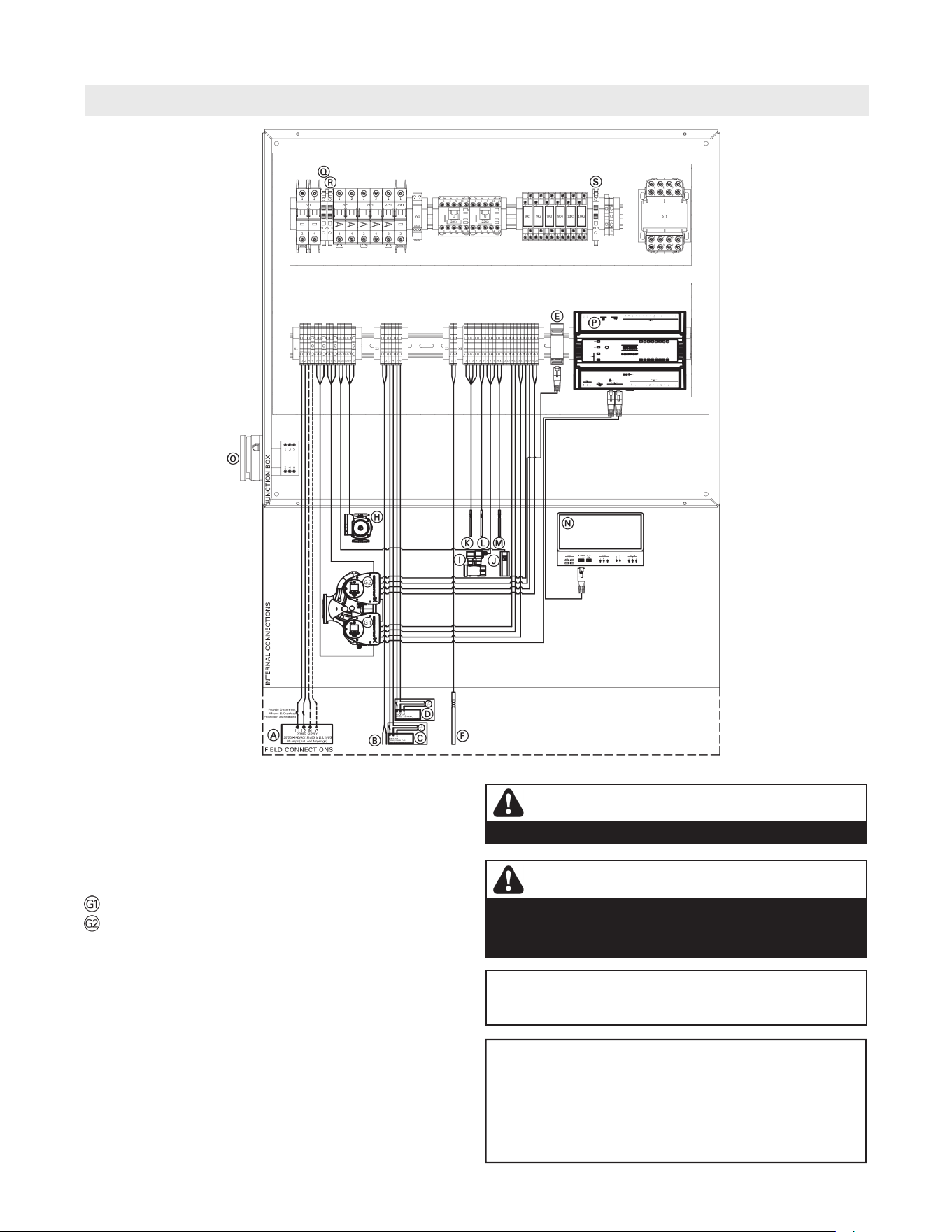
72
5833 275 - 07
Vitotrans 300 Installation, Operating and Service
Wiring Diagram - S3HA 90 and D3HA 90
Wiring
If any of the original wires as supplied with the appliance
must be replaced, it must be replaced with the exact
equivalent.
WARNING
DISCONNECT POWER BEFORE SERVICING THE VITOTRANS.
CAUTION
Label all wires prior to disconnection when servicing
controls. Wiring errors can cause improper and dangerous
operation. Verify proper operation after servicing.
Electrical Installations must comply with:
In the USA National Electric Code (NEC), ANSI/NFPA
70 and any other national, state and local codes and/or
regulations.
In Canada, the Canadian Electrical Code (CEC), CSA
C22.1 Canadian Electrical Code Part 1 and any other
province, territory, local codes and/or regulations.
Legend
A Power supply 120/208-240VAC/1Ph/60 Hz L1/L2/N/G
B Boiler demand (dry contact)
C Building DHW re-circulation pump (dry contact)
D DHW storage tank (dry contact)
E BACnet (IP) communication RJ45
F DHW storage tank temperature sensor
Heating system pump (head 1)
Heating system pump (head 2)
H Internal de-scaling pump
I Domestic cold water flow sensor
J Manual reset fixed high limit 210ºF (99ºC )
K DHW temperature sensor
L DCW temperature sensor
M System return temperature sensor
N Touch screen user interface
O Main disconnect switch
P Control PLC
Q Fuse, T 0.5A/250VAC
R Fuse, T 0.25A/250VAC
S Fuse, F 4A

73
5833 275 - 07
Vitotrans 300 Installation, Operating and Service
Specification
Technical Data
Models S3HA 30 D3HA 30 S3HA 60 D3HA 60 S3HA 90 D3HA 90
Heating input MBH
(kW)
2100
(615)
2100
(615)
4200
(1231)
4200
(1231)
6300
(1846)
6300
(1846)
Power supply Voltage (AC)
Phase
FLA
Hz
240
1
20
60
240
1
20
60
240
1
20
60
240
1
20
60
240
1
20
60
240
1
20
60
Overall length in.
(mm)
73c
(1896)
73c
(1896)
73c
(1896)
73c
(1896)
73c
(1896)
73c
(1896)
Overall width in.
(mm)
26b
673
26b
673
26b
673
26b
673
26b
673
26b
673
Overall height *1 in.
(mm)
62a
(1584)
62a
(1584)
62a
(1584)
62a
(1584)
62a
(1584)
62a
(1584)
Weight (without water) lb.
(Kg)
1037
(470)
1082
(491)
1123
(509)
1223
(550)
1273
(577)
1408
(639)
Weight (with water) lb.
(Kg)
1107
(502)
1155
(524)
1222
(554)
1319
(598)
1404
(637)
1549
(703)
Water content heating system USG
(L)
4.4
(16.2)
4.6
(17.4)
6.2
(23.5)
6.6
(25.0)
8.0
(30.3)
8.6
(32.6)
Water content domestic USG
(L)
4
(15.1)
4.2
(15.9)
5.7
(21.6)
6.1
(23.1)
7.7
(29.1)
8.3
(31.4)
Heat exchanger surface area ft.
2
(m
2
)
69.6
(6.47)
81.2
(7.54)
139.2
(12.93)
162.4
(15.09)
208.8
(19.40)
243.6
(22.63)
Max. boiler supply
temperature
ºF
(ºC)
230
(110)
230
(110)
230
(110)
230
(110)
230
(110)
230
(110)
Max. domestic hot water
supply temperature (FHL)
ºF
(ºC)
210
(99)
210
(99)
210
(99)
210
(99)
210
(99)
210
(99)
Maximum operating pressure psig
(bar)
150
(10.3)
150
(10.3)
150
(10.3)
150
(10.3)
150
(10.3)
150
(10.3)
Boiler supply connection (NPT) in.
(mm)
2b
65
2b
65
2b
65
2b
65
2b
65
2b
65
Boiler return connection (NPT) in.
(mm)
2b
65
2b
65
2b
65
2b
65
2b
65
2b
65
DCW connection (NPT) in.
(mm)
2
50
2
50
2
50
2
50
2
50
2
50
DHW connection (NPT) in.
(mm)
2
50
2
50
2
50
2
50
2
50
2
50
Max DHW flow GPM
(L/min)
60
(227)
60
(227)
120
(454)
120
(454)
180
(681)
180
(681)
Heating system
circulating pump *2
Model 65-150 65-150 65-150 65-150 65-150
Dual
65-150
Dual
*1 Overall height does not include leveling feet or seismic brackets.
*2 The heating system circulating pump is built for the Vitotrans 300 and any replacement parts must be ordered
from Viessmann.
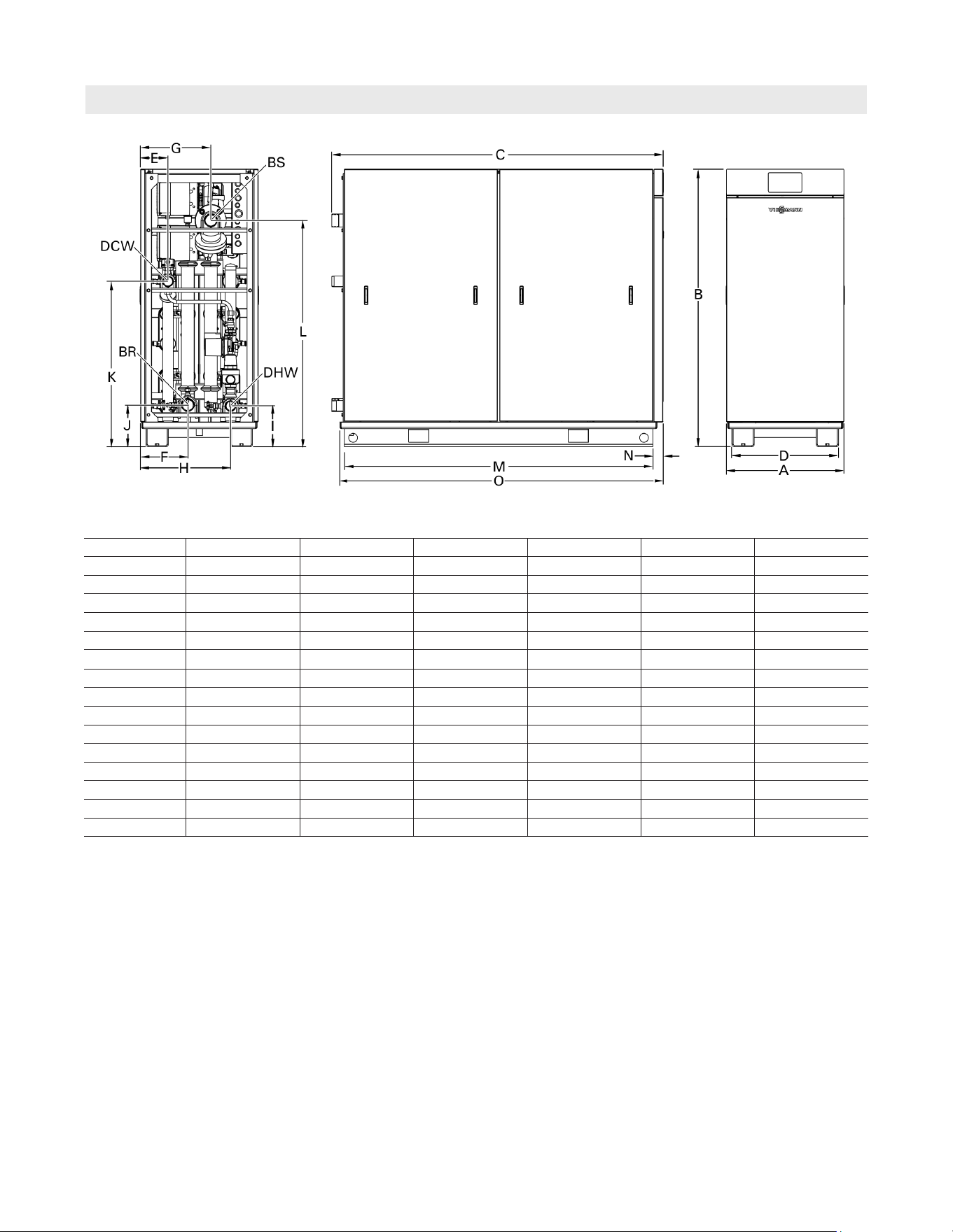
74
5833 275 - 07
Vitotrans 300 Installation, Operating and Service
Specification
Dimensions
*1 *Height Does not include the use of leveling feet [+ up to 2 in. (50 mm)], or seismic feet [+2b in. (60 mm)].
Note: dimensional tolerance of ! a in. (! 5 mm)
Dimensions
Models S3HA 30 D3HA 30 S3HA 60 D3HA 60 S3HA 90 D3HA 90
A in. (mm) 26½ (673) 26½ (673) 26½ (673) 26½ (673) 26½ (673) 26½ (673)
B*1 in. (mm) 62¼ (1584) 62¼ (1584) 62¼ (1584) 62¼ (1584) 62¼ (1584) 62¼ (1584)
C in. (mm) 74¾ (1896) 74¾ (1896) 74¾ (1896) 74¾ (1896) 74¾ (1896) 74¾ (1896)
D in. (mm) 24 (610) 24 (610) 24 (610) 24 (610) 24 (610) 24 (610)
E in. (mm) 6¼ (157) 6¼ (157) 6¼ (157) 6¼ (157) 6¼ (157) 6¼ (157)
F in. (mm) 10¾ (271) 10¾ (271) 10¾ (271) 10¾ (271) 10¾ (271) 10¾ (271)
G in. (mm) 15¾ (403) 15¾ (403) 15¾ (403) 15¾ (403) 15¾ (403) 15¾ (403)
H in. (mm) 20¼ (516) 20¼ (516) 20¼ (516) 20¼ (516) 20¼ (516) 20¼ (516)
I*1 in. (mm) 9¼ (232) 9¼ (232) 9¼ (232) 9¼ (232) 9¼ (232) 9¼ (232)
J*1 in. (mm) 9¼ (237) 9¼ (237) 9¼ (237) 9¼ (237) 9¼ (237) 9¼ (237)
K*1 in. (mm) 37¼ (943) 37¼ (943) 37¼ (943) 37¼ (943) 37¼ (943) 37¼ (943)
L*1 in. (mm) 50¾ (1291) 50¾ (1291) 50¾ (1291) 50¾ (1291) 50¾ (1291) 50¾ (1291)
M in. (mm) 69½ (1765) 69½ (1765) 69½ (1765) 69½ (1765) 69½ (1765) 69½ (1765)
N in. (mm) 2¼ (59) 2¼ (59) 2¼ (59) 2¼ (59) 2¼ (59) 2¼ (59)
O in. (mm) 72¾ (1850) 72¾ (1850) 72¾ (1850) 72¾ (1850) 72¾ (1850) 72¾ (1850)
Legend
BS Boiler Supply (heating system supply)
BR Boiler Return (heating system return)
DHW Domestic Hot Water
DCW Domestic Cold Water
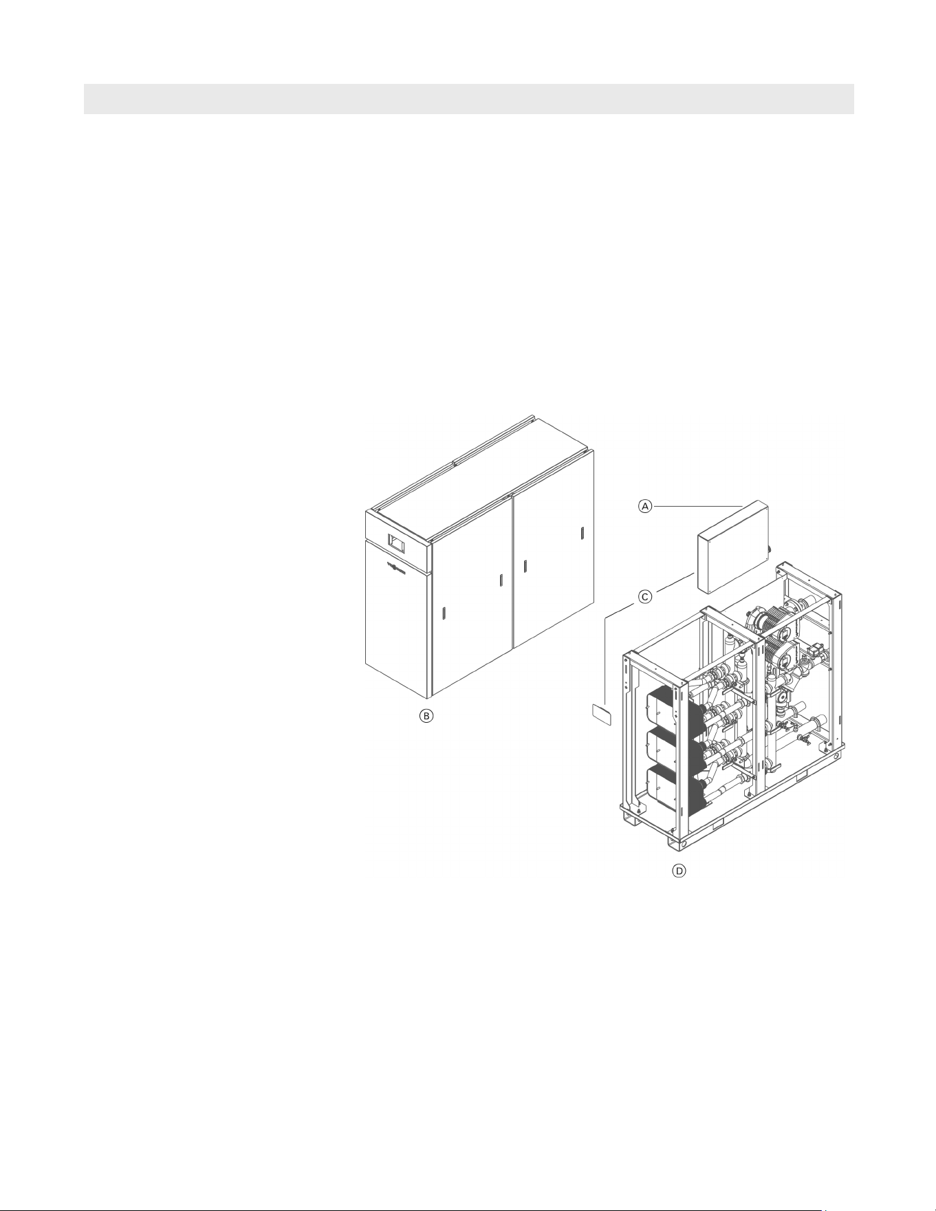
75
5833 275 - 07
Vitotrans 300 Installation, Operating and Service
Parts List
Parts
Model No. Serial No.
S3HA 30 7723997jjjjjjjjj
S3HA 60 7723998jjjjjjjjj
S3HA 90 7723999jjjjjjjjj
D3HA 30 7725000jjjjjjjjj
D3HA 60 7725001jjjjjjjjj
D3HA 90 7725002jjjjjjjjj
Ordering Parts:
Please provide Model and Serial Number from rating
plate A when ordering replacement parts. Order
replacement components from your Viessmann
distributor.
Overview of Assemblies
A Rating Plate with Serial Number
(affixed on Control Assembly cover,
beneath side panel of Vitotrans 300)
B Enclosure Assembly
C Control Assembly
D Heat Exchanger Assembly
Other Parts (not illustrated)
0001 Installation Set (see page 86)
0002 Technical Literature Set
0003 Technical Data Manual
0004 Installation, Operation and
Service Instructions
0005 Wiring Diagram
0006 Warranty Sheet
0007 Parts List, Vitotrans 300
0008 Parts List, Installation Set
0009 Touch-up paint stick, Vitotec silver
0010 Touch-up spray paint, Vitotec silver
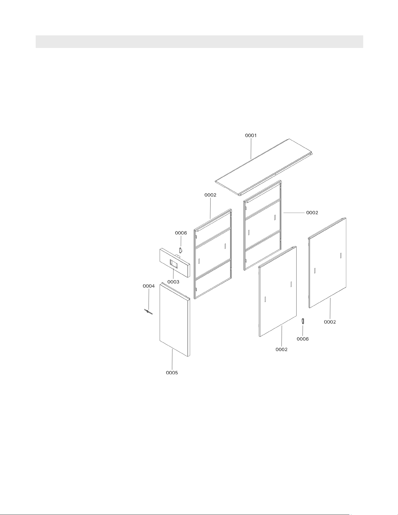
76
5833 275 - 07
Vitotrans 300 Installation, Operating and Service
Parts List (continued)
Parts
Model No. Serial No.
S3HA 30 7723997jjjjjjjjj
S3HA 60 7723998jjjjjjjjj
S3HA 90 7723999jjjjjjjjj
D3HA 30 7725000jjjjjjjjj
D3HA 60 7725001jjjjjjjjj
D3HA 90 7725002jjjjjjjjj
Parts for Enclosure Assembly
0001 Top panel
0002 Side panel
0003 Front panel, top
0004 Nameplate, “Viessmann”
0005 Front panel, bottom
0006 Handle (each)
Other Parts (not illustrated)
0007 Label GRY/CLR “VITOTRANS 300”
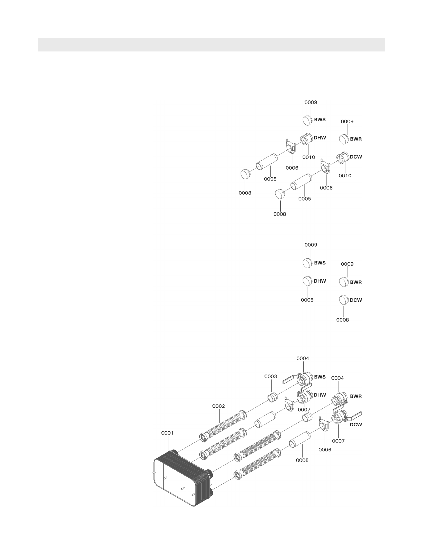
77
5833 275 - 07
Vitotrans 300 Installation, Operating and Service
Parts List (continued)
Parts
Model No. Serial No.
S3HA 30 7723997jjjjjjjjj
D3HA 30 7725000jjjjjjjjj
Parts for Single Heat Exchanger Units
0001 Plate heat exchanger LC 110, 2 in. *1
0002 Flex pipe, 2 x 18 in. SS *2
0003 Nipple, 2 x 2 in. BMI
0004 Ball valve, 2 in.
0005 Nipple, 2 x 7 in. SS *2
0006 Clamp, 2 in.
0007 Ball Valve, 2 in. lead free *2
0008 Cap, 2” SS *2
0009 Cap, 2 in. BMI
0010 Coupling, 2 in. SS *2
*1 Important: Use double wall plate heat
exchanger for D3HA 30.
*2 Important: Ensure only stainless steel or
lead free replacement parts are used on
domestic water side.
BWS Boiler Water Supply
BWR Boiler Water Return
DHW Domestic Hot Water
DCW Domestic Cold Water
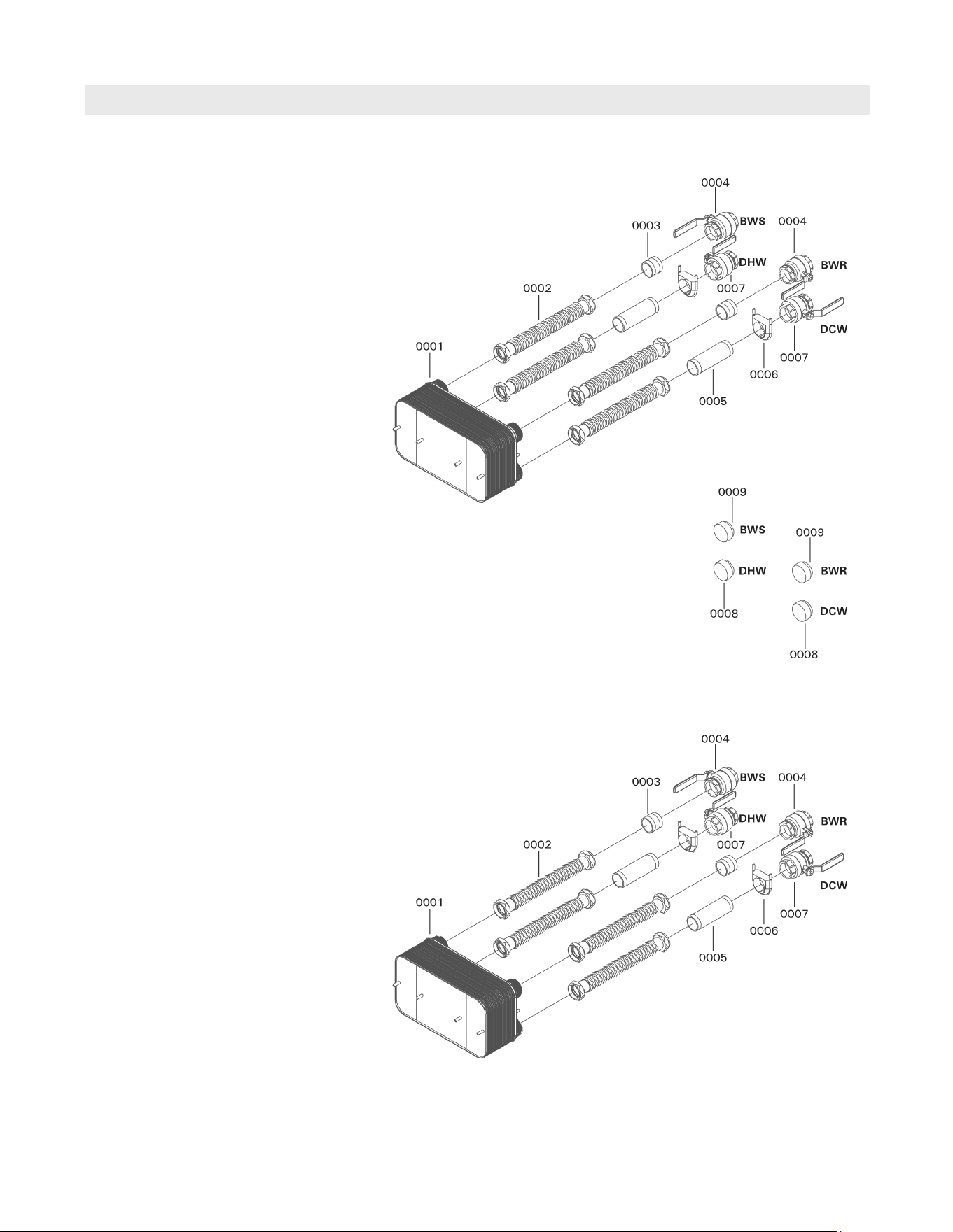
78
5833 275 - 07
Vitotrans 300 Installation, Operating and Service
Parts List (continued)
Parts
Model No. Serial No.
S3HA 60 7723998jjjjjjjjj
D3HA 60 7725001jjjjjjjjj
Parts for Double Heat Exchanger Units
0001 Plate heat exchanger LC 110, 2 in. *1
0002 Flex pipe, 2 x 18 in. SS *2
0003 Nipple, 2 x 2 in. BMI
0004 Ball valve, 2 in.
0005 Nipple, 2 x 7 in. SS *2
0006 Clamp, 2 in.
0007 Ball Valve, 2” lead free *2
0008 Cap, 2 in. SS *2
0009 Cap, 2 in. BMI
*1 Important: Use double wall plate heat
exchanger for D3HA 60.
*2 Important: Ensure only stainless steel or
lead free replacement parts are used on
domestic water side.
BWS Boiler Water Supply
BWR Boiler Water Return
DHW Domestic Hot Water
DCW Domestic Cold Water
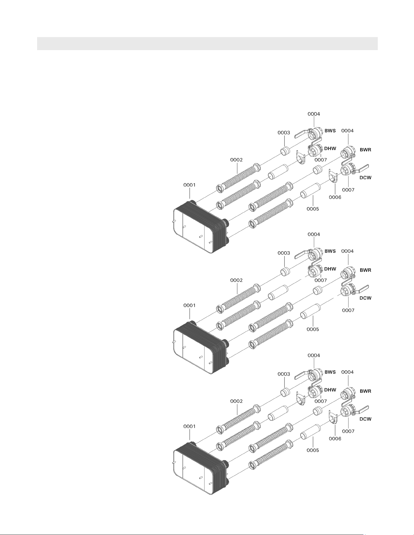
79
5833 275 - 07
Vitotrans 300 Installation, Operating and Service
Parts List (continued)
Parts
Model No. Serial No.
S3HA 90 7723999jjjjjjjjj
D3HA 90 7725002jjjjjjjjj
Parts for Triple Heat Exchanger Units
0001 Plate heat exchanger LC 110, 2 in. *1
0002 Flex pipe, 2” x 18 in. SS *2
0003 Nipple, 2 x 2 in. BMI
0004 Ball valve, 2 in.
0005 Nipple, 2 in. x 7” SS *2
0006 Clamp, 2 in.
0007 Ball Valve, 2 in. lead free *2
*1 Important: Use double wall plate heat
exchanger for D3HA 90.
*2 Important: Ensure only stainless steel or
lead free replacement parts are used on
domestic water side.
BWS Boiler Water Supply
BWR Boiler Water Return
DHW Domestic Hot Water
DCW Domestic Cold Water
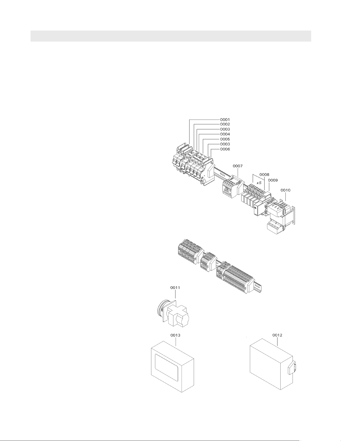
80
5833 275 - 07
Vitotrans 300 Installation, Operating and Service
Parts List (continued)
Parts
Model No. Serial No.
S3HA 30 7723997jjjjjjjjj
S3HA 60 7723998jjjjjjjjj
D3HA 30 7725000jjjjjjjjj
D3HA 60 7725001jjjjjjjjj
Parts for Control Assembly
for units with a single head pump
0001 Circuit breaker, 20A 2P
0002 Fuse T 0.5A (set of 5)
0003 Fuse, T 0.25A/250VAC
0004 Fuse F 4A (set of 5)
0005 Circuit breaker, 10A 2P
0006 Circuit breaker, 5A 1P
0007 Contactor, 12A 3P 120V
0008 Relay, 24V
0009 Power Supply, 5VDC 7.5W
0010 Transformer, 120/240-12/24V 50VA
0011 Disconnect switch, 20A 3P
0012 Controller, ECY-303
(factory programmed)
0013 Circuit Board
control software and touchscreen
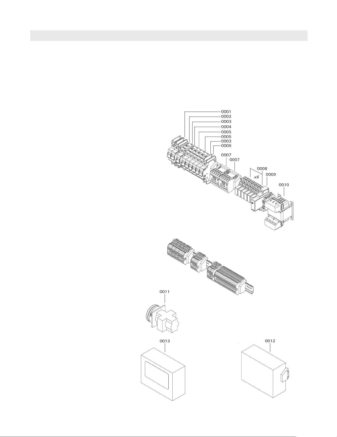
81
5833 275 - 07
Vitotrans 300 Installation, Operating and Service
Parts List (continued)
Parts
Model No. Serial No.
S3HA 90 7723999jjjjjjjjj
D3HA 90 7725002jjjjjjjjj
Parts for Control Assembly
for units with a dual head pump
0001 Circuit breaker, 20A 2P
0002 Fuse T 0.5A (set of 5)
0003 Fuse, T 0.25A/250VAC
0004 Fuse F 4A (set of 5)
0005 Circuit breaker, 10A 2P
0006 Circuit breaker, 5A 1P
0007 Contactor, 12A 3P 120V
0008 Relay, 24V
0009 Power Supply, 5VDC 7.5W
0010 Transformer, 120/240-12/24V 50VA
0011 Disconnect switch, 20A 3P
0012 Controller, ECY-303
(factory programmed)
0013 Circuit Board control software and touchscreen
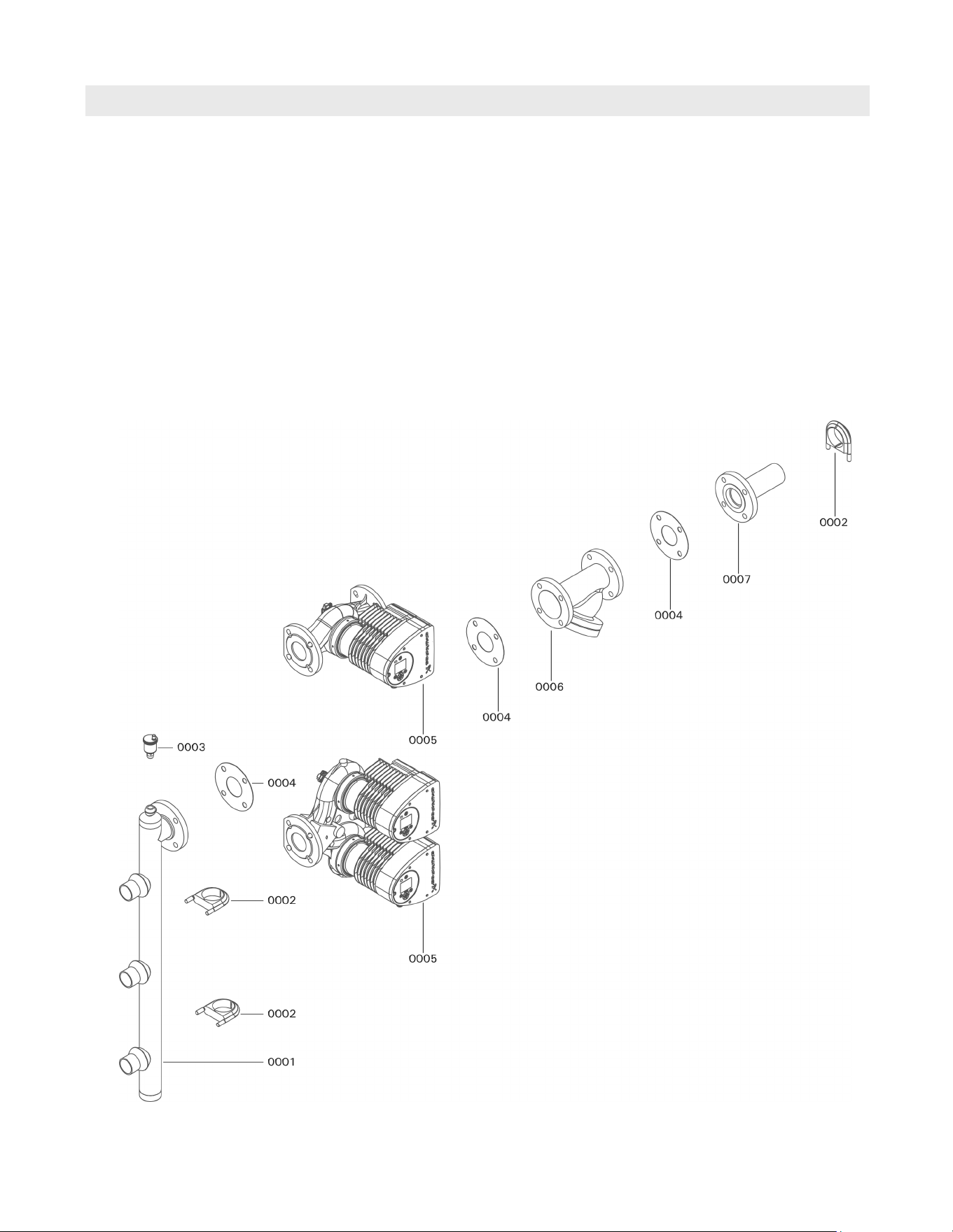
82
5833 275 - 07
Vitotrans 300 Installation, Operating and Service
Parts List (continued)
Parts
Model No. Serial No.
S3HA 30 7723997jjjjjjjjj
S3HA 60 7723998jjjjjjjjj
S3HA 90 7723999jjjjjjjjj
D3HA 30 7725000jjjjjjjjj
D3HA 60 7725001jjjjjjjjj
D3HA 90 7725002jjjjjjjjj
Parts for Hydraulics
Connection Pipe for Boiler Water Supply
0001 Connection pipe 1, heating supply
0002 Clamp, 2½ in.
0003 Air vent with shut-off base, 3/8 in.
0004 Gasket, 2½ in. flat face Blue-Gard
0005 Pump Head, Magna3 65-150 208-230V
0006 Strainer, 2½ in. Y-Type flanged
0007 Connection pipe 2, heating supply
Other Parts (not illustrated)
0008 Communication module, CIM 500
0009 Sensor kit, Magna3
0010 Control box kit, Magna3 1600W
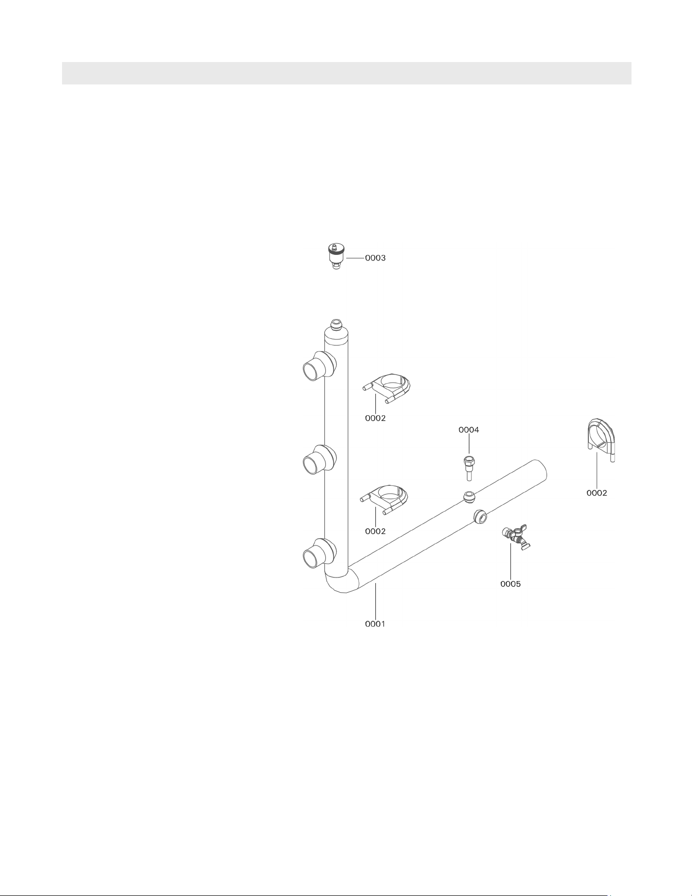
83
5833 275 - 07
Vitotrans 300 Installation, Operating and Service
Parts List (continued)
Parts
Model No. Serial No.
S3HA 30 7723997jjjjjjjjj
S3HA 60 7723998jjjjjjjjj
S3HA 90 7723999jjjjjjjjj
D3HA 30 7725000jjjjjjjjj
D3HA 60 7725001jjjjjjjjj
D3HA 90 7725002jjjjjjjjj
Parts for Hydraulics
Connection Pipe for Boiler Water Return
0001 Connection pipe, heating return
0002 Clamp, 2½ in.
0003 Air vent with shut-off base, 3/8 in.
0004 Sensor well, TH 60V
0005 Drain valve, ¾ in.
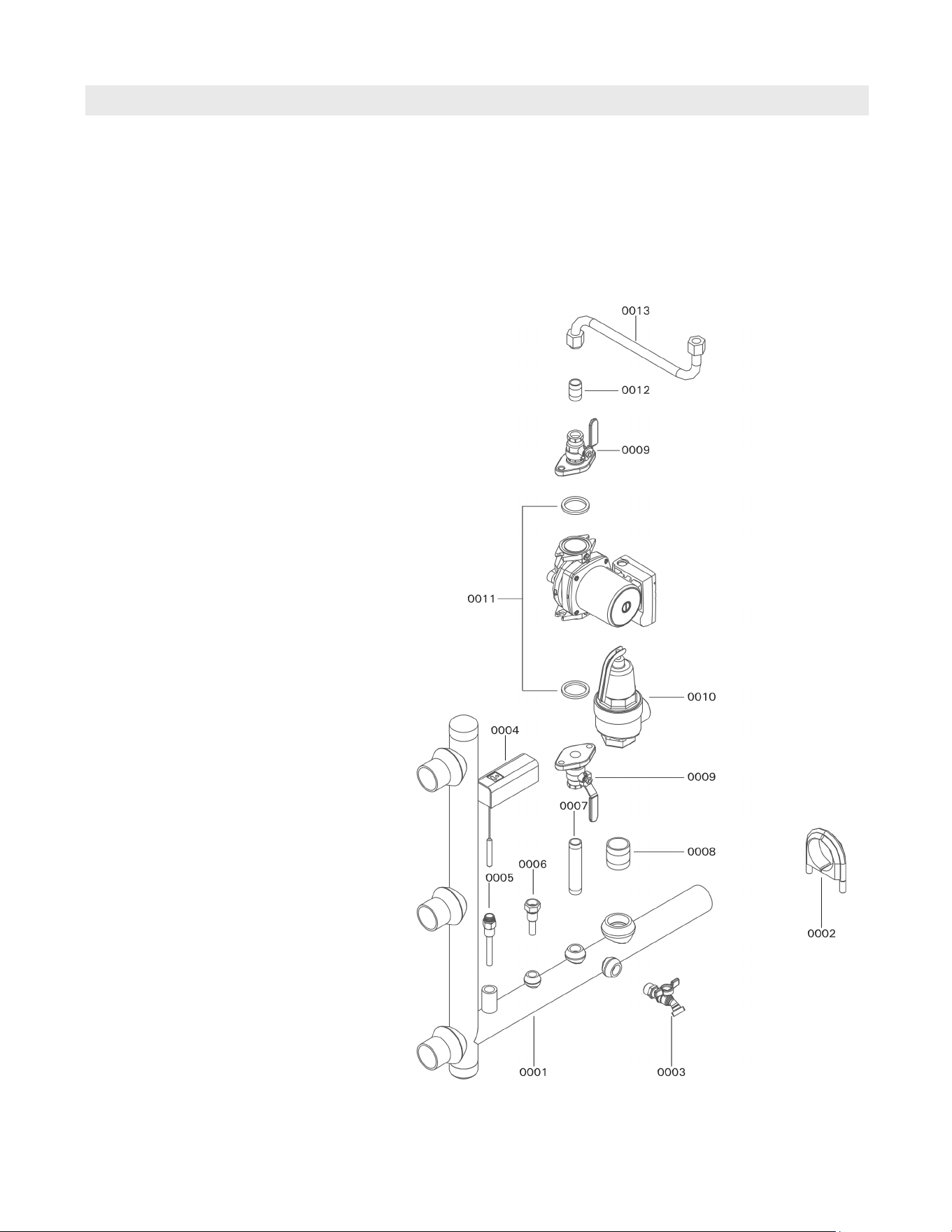
84
5833 275 - 07
Vitotrans 300 Installation, Operating and Service
Parts List (continued)
Parts
Model No. Serial No.
S3HA 30 7723997jjjjjjjjj
S3HA 60 7723998jjjjjjjjj
S3HA 90 7723999jjjjjjjjj
D3HA 30 7725000jjjjjjjjj
D3HA 60 7725001jjjjjjjjj
D3HA 90 7725002jjjjjjjjj
Parts for Hydraulics
Connection Pipe for Domestic Hot Water *1
0001 Connection pipe, DHW hydraulic SS
0002 Clamp, 2 in.
0003 Drain valve, ¾ in. lead free
0004 Aquastat, L4006H1004/U
0005 Sensor well, ½ x 3 in. SS
0006 Sensor well, TH 60V SS
0007 Nipple, ¾ x 5 in. SS
0008 Nipple, 1½ x 2 in. SS
0009 Flange set, ¾ in. Check-Trol lead free
0010 Pressure relief valve, 1½ in. 150 psi lead free
0011 Pump, NBF-36 BRZ lead free
0012 Nipple, ¾ x 1 in. SS
0013 Flex pipe, ¾ x 24 in. SS
*1 Important: Ensure only stainless steel or
lead free replacement parts are used on
domestic water side.
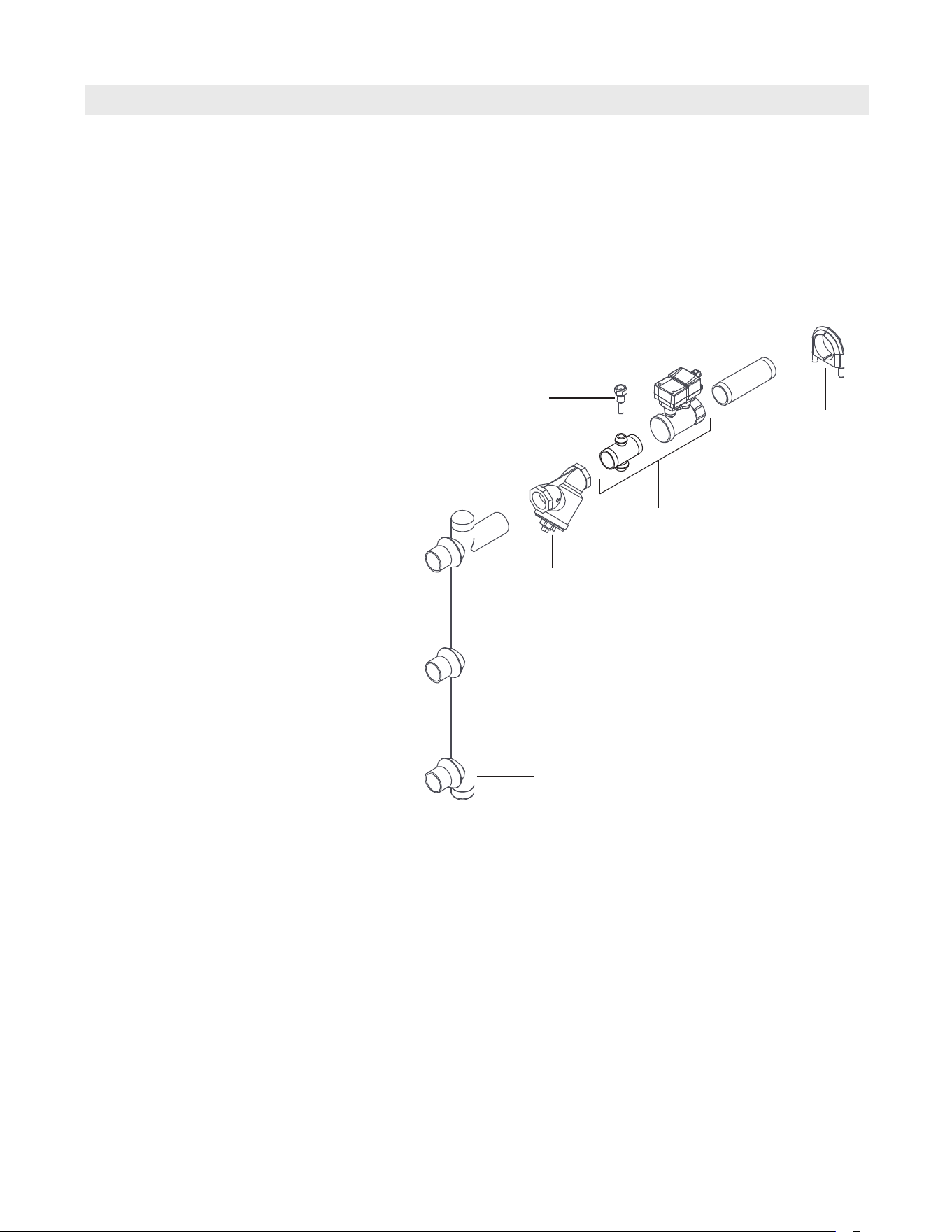
85
5833 275 - 07
Vitotrans 300 Installation, Operating and Service
Parts List (continued)
Parts
Model No. Serial No.
S3HA 30 7723997jjjjjjjjj
S3HA 60 7723998jjjjjjjjj
S3HA 90 7723999jjjjjjjjj
D3HA 30 7725000jjjjjjjjj
D3HA 60 7725001jjjjjjjjj
D3HA 90 7725002jjjjjjjjj
Parts for Hydraulics
Connection Pipe for Domestic Cold Water *1
0001 Connection pipe, DCW hydraulic SS
0002 Strainer, 2 in. Y-Type lead free
0003 DCW Connection Pipe Cross & Flow Sensor
0004 Nipple, 2 x 6 in. SS
0005 Clamp, 2 in.
0006 Sensor well, TH 60V SS
*1 Important: Ensure only stainless steel or
lead free replacement parts are used on
domestic water side.
0003
0004
0005
0006
0002
0001
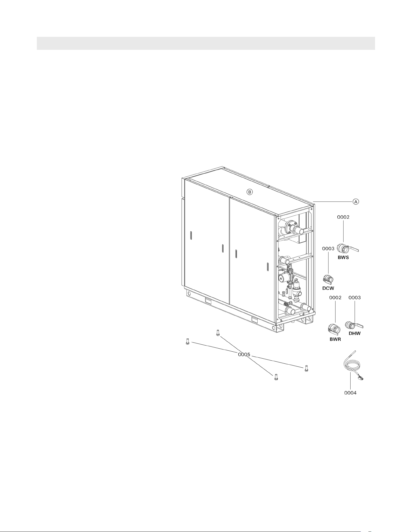
86
5833 275 - 07
Vitotrans 300 Installation, Operating and Service
Installation Fittings
Parts
Model No. Serial No.
S3HA 30 7723997jjjjjjjjj
S3HA 60 7723998jjjjjjjjj
S3HA 90 7723999jjjjjjjjj
D3HA 30 7725000jjjjjjjjj
D3HA 60 7725001jjjjjjjjj
D3HA 90 7725002jjjjjjjjj
Ordering Parts:
Please provide Model and Serial Number
A when ordering replacement parts. Order
replacement components from your Viessmann
distributor.
Parts
0002 Ball valve, 2½ in.
0003 Ball valve, 2 in. *1
0004 Immersion sensor, for low-loss header
0005 Leveling bolt (each)
Other Parts (not illustrated)
0011 Technical Literature Set
0012 Technical Data Manual
0013 Installation, Operation and
Service Instructions
0014 Wiring Diagram
0015 Warranty Sheet
0016 Parts List, Vitotrans 300
0017 Parts List, Installation Set
0018 Touch-up paint stick, Vitotec silver
0019 Touch-up spray paint, Vitotec silver
*1 Important: Ensure only stainless steel
or lead free replacement parts are used on
domestic water side.
BWS Boiler Water Supply
BWR Boiler Water Return
DHW Domestic Hot Water
DCW Domestic Cold Water
A Rating Plate with Serial Number
(affixed on Control Assemly cover,
beneath side panel of Vitotrans 300)

87
5833 275 - 07
Vitotrans 300 Installation, Operating and Service
Maintenance
Maintenance
Maintenance Record
Startup Maintenance/Service Maintenance/Service Maintenance/Service
date:
by:
Maintenance/Service Maintenance/Service Maintenance/Service Maintenance/Service
date:
by:
Maintenance/Service Maintenance/Service Maintenance/Service Maintenance/Service
date:
by:
Maintenance/Service Maintenance/Service Maintenance/Service Maintenance/Service
date:
by:
Maintenance/Service Maintenance/Service Maintenance/Service Maintenance/Service
date:
by:
Maintenance/Service Maintenance/Service Maintenance/Service Maintenance/Service
date:
by:
Interval Maintenance
Weekly Double-Wall heat exchangers only. Check for leakage.
Quarterly Every three months. Check the operation of the high limit switch install on the DHW
manifold.
Semi-annually Evert six months. Check the strainers on both the boiler water and the domestic water
piping side.
Annually Once a year. Check the temperature sensors.
Once a year. Check the operation of the internal system pump and internal descaling
pump.
Periodic Periodic cleaning of the heat exchanger may be necessary, depending on conditions
and settings.
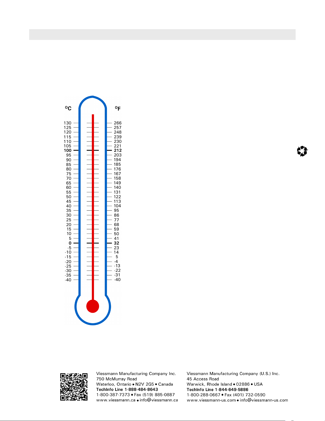
5833 275 - 07
Vitotrans 300 Installation, Operating and Service
Technical information subject to change without notice.
Printed on environmentally friendly
(recycled and recyclable) paper.
Scan for
digital copy
of this
document