Installation and Service
Instructions
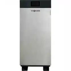
VITOTRON 100
5472 726 - 06 09/2024
For use by heating contractor
Please file in Service Binder
Read and save these instructions
for future reference.
Product may not be exactly as shown
IMPORTANT
Vitotron 100 VLN2
Models 04 to 14.4
Wall-mounted Electric Boiler
Heating input: 13.6 to 49.1 MBH
4.0 to 14.4 kW

2
5472 726 - 06
Vitotron 100 Electric Boiler Installation/Service
Safety Instructions .....................................................3
Electric Boiler Ratings and Specification ...................... 4
Electric Boiler Mounting Clearances ..............................5
Piping Arrangement ....................................................6
Sizing the Electric Boiler ..............................................7
Designed Temperature Differential ..............................7
Circulating Pump Information ......................................7
Plumbing Installation Guidelines ...................................8
Electrical Installation ................................................. 10
Control Panel ...........................................................12
Heating Mode / Initial Start-Up ...................................13
Winter Mode (Heating Mode) .......................................13
Summer Mode (Stand-by Mode) ....................................16
Advanced Settings ...................................................17
Troubleshooting .......................................................18
Care and Maintenance ..............................................18
General View of the Electric Boiler .............................. 19
Parts List .................................................................20
Electric Boiler Parts ...................................................21
Instructions for the Installer
Instructions for the User
Page
Table of Contents
This appliance is not intended for use by persons
(including children) with reduced physical, sensory or
mental capabilities or lack of experience and knowledge,
unless they have been given supervision or instruction
concerning use of the appliance by a person responsible
for their safety. Children should be supervised to ensure
that they do not play with the electric boiler appliance.
Consider all piping and electrical connections before
selecting electric boiler location.
Failure to follow the instructions in this manual could
result in severe personal injury, death or property damage.
IMPORTANT

3
5472 726 - 06
Vitotron 100 Electric Boiler Installation/Service
Instructions for the Installer
Safety Instructions
8. This electric boiler is equipped with a 194°F manual
reset safety high limit device. The reset button is
clearly located in the center of this device.
9. This electric boiler will not operate below a 7 psi
water pressure level.
10. This electric boiler is equipped with a circulator
pump. After thermostat temperature set point
has been reached the pump will continue to
circulate water as part of a post purge sequence to
push heated water away from heat exchanger.
11. This electric boiler is equipped with a differential
pressure relief bypass valve. It allows the system
to keep minimal flow of heating water through
the electric boiler and reduce noise in the installation
when equipped with thermostatic zone valves.
12. Do not drain the water from the electric boiler after
the heating season.
13. In summer do not shut off the power supply (120VAC
and 240VAC) and leave the controller in stand-by
(summer mode) between the heating seasons. The
electric boiler is equipped with an exercise timer
control feature that allows the circulating pump to
operate 15 minutes each day and will ensure longer
operation the circulating pump and will help to
eliminate the buildup of debris. (See section “Summer
mode (stand-by mode)”on page 11).
14. The electric boiler is pre-set by the manufacturer to
work with hydronic radiant floor, radiant ceiling,
hot water baseboard and water to air heat
applications. Temperature adjustments can be made
on the control panel to meet these applications
requiring desired water temperatures between 85° -
140°F.
1. Read and strictly follow the installation and operating
instructions to ensure a longevity and reliable electric
boiler operation.
2. This manual provides general installation guidelines.
Your installation must comply with ALL applicable
local codes.
3. 1 Always have a qualified electrician perform
electrical wiring. Manufacturer will not be held
responsible for faulty installations which are performed
by unqualified electricians. An efficient electrical
installation which has been completed in accordance
with the binding norms of electric installation.
Electric installation should be equipped with electric
circuit breakers and other solutions which will ensure
disconnecting the electric boiler from the source of
power.
4. All installation work must be performed when the
power and water supply is disconnected from the
main electrical panel.
5. This electric boiler must be installed vertically and on
an even wall surface with access to plumbing
connections on bottom.
6. Any associated components (i.e. electric boiler,
water tubing, valves, manifolds etc...) must be
flushed before electric boiler installation.
7. This electric boiler is equipped with a safety relief
valve. Do not install any barrier fitting or valve on the
outlet of the safety valve. Connect and extend
c in. copper piping from relief valve and terminate
within 6 in. of the floor or floor drain.
4
5472 726 - 06
Vitotron 100 Electric Boiler Installation/Service
Instructions for the Installer
Electric Boiler Ratings and Specifications
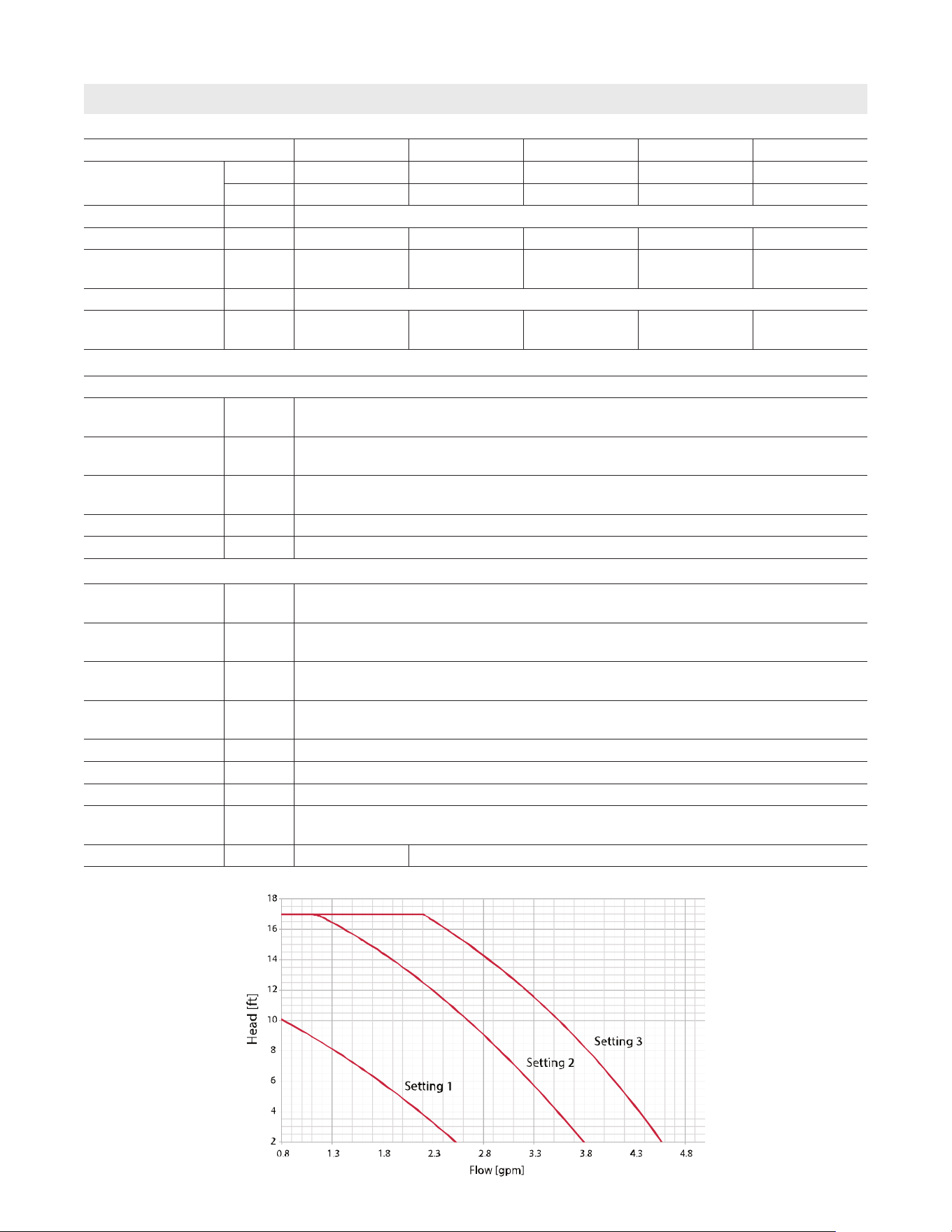
Electric Boiler Model VLN2 04 VLN2 06 VLN2 08 VLN2 12 VLN2 14.4
Electric Boiler
Rated Power
kW 4 6 8 12 14.4
Btu/h 13,652 20,478 27,304 40,956 49,147
Voltage V 240
Rated Current A 16.66 25.0 33.3 50.0 60.0
Breaker Quantity-
Amps
A 1 @
30 amp
1 @
40 amp
1 @
50 amp
1 @
60/70 amp
1 @
80 amp
Heating Elements Quantity 3
Element Resistance
/ each
Ω 43.3 28.8 21.6 14.4 12.0
Circulating Pump - Wilo Star S 21 U 15. 3 speed
Pump Power
Supply
120V, 1 Ph, 60Hz 12 Amp
Circulating Pump
Voltage
V 120V, 60Hz
Circulating Pump
Amps
A .97
Speeds 3
Fuse Rating 2.0 amp
Operating
Temperature Range
°F 85° - 140°
Inlet / Outlet
Pipe Thread
G c in. (Internal Thread)
Expansion Vessel
(14 psi)
Gallon 1.6
Safety Relief Valve
Rating
psi 30
Maximum Pressure psi 30
Minimum Pressure psi 7
Weight Lbs. 68.5
Dimensions
L x W x D
Inches 28 x 17 x 9
7
/
8
Minimum Flow Rate gpm 1.1 1.32
Residual Head
5
5472 726 - 06
Vitotron 100 Electric Boiler Installation/Service
Instructions for the Installer
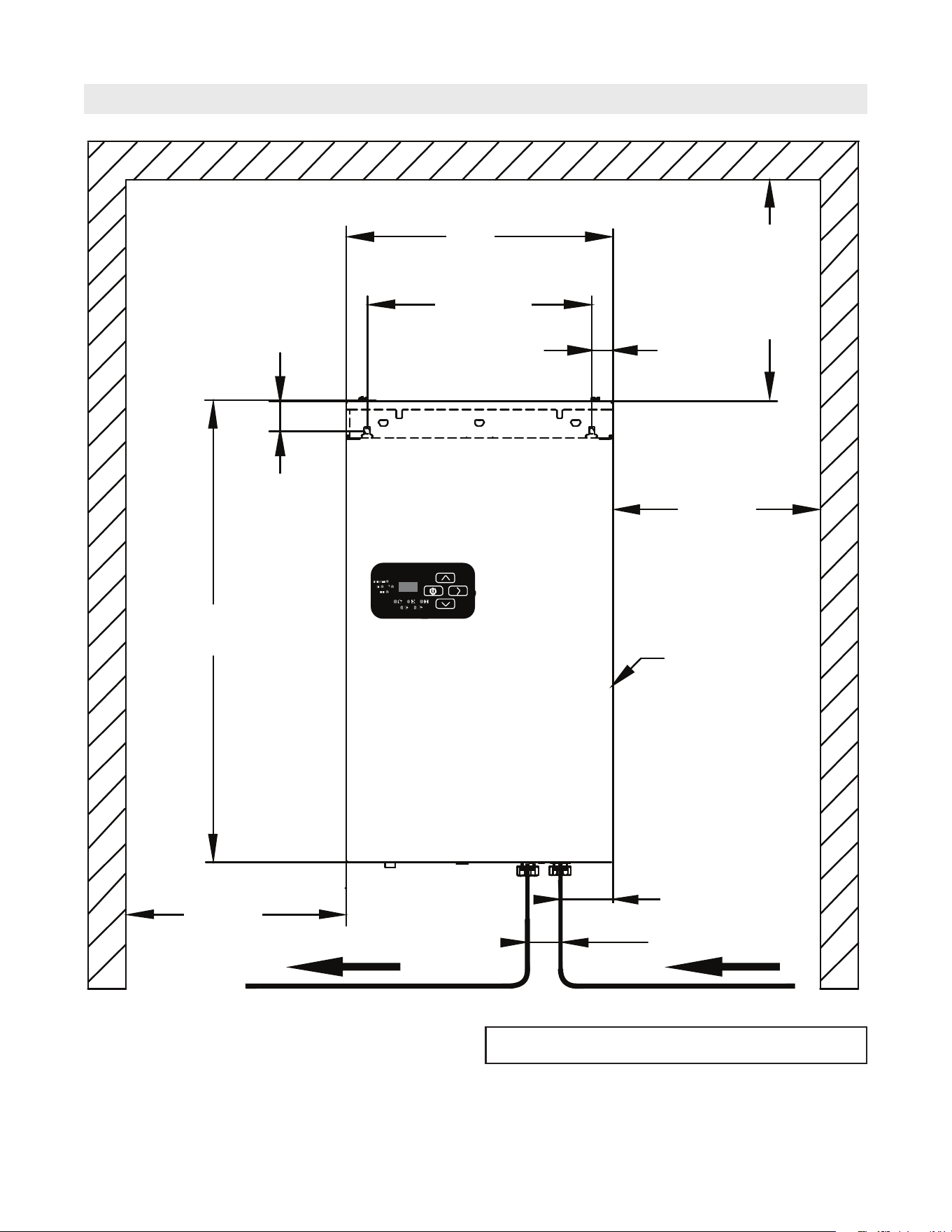
Electric Boiler Mounting Clearances
After reading instructions, please keep this manual with
the electric boiler for future reference.
IMPORTANT
17 in.
13 - 13⁄16 in.
1 - 3⁄8 in.
Min. 2 in.
1- 5⁄16 in.
Min. 5 - 7⁄8 in.
28 in.
Min. 2 in.
9 - 7⁄8 in. Depth
3 - 11⁄16 in.
2 - 3⁄16 in.
6
5472 726 - 06
Vitotron 100 Electric Boiler Installation/Service
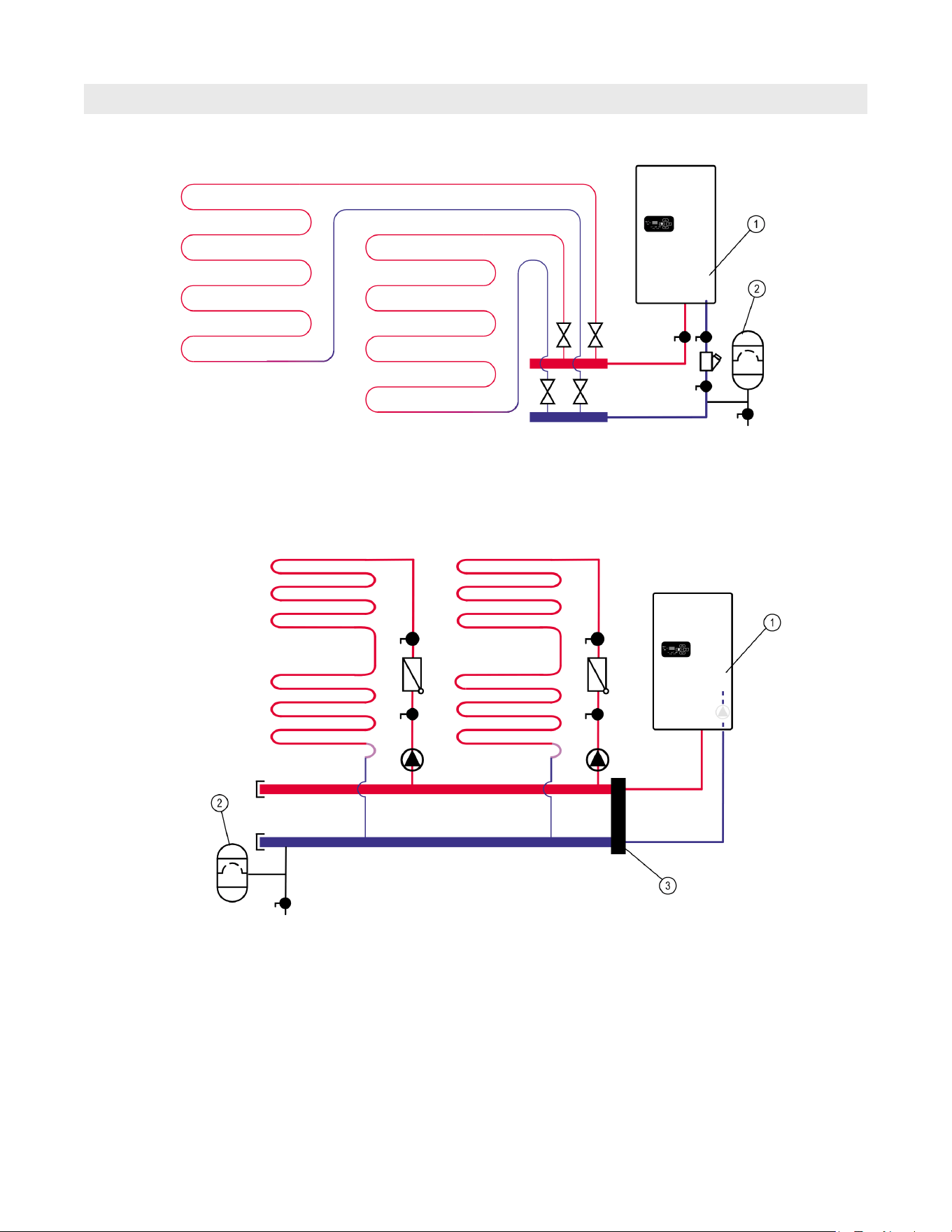
Piping Arrangement
Instructions for the Installer
Typical radiant floor heating application
1 Electric Boiler
2 Additional expansion tank - if needed
Electric boiler piped in a primary/secondary (P/S)
configuration. Use primary/secondary piping when the
system flow rates exceed the stated boiler flow rate.
1 Electric Boiler
2 Additional expansion tank - if needed
3 Low loss header
7
5472 726 - 06
Vitotron 100 Electric Boiler Installation/Service
Sizing of the Boiler
Instructions for the Installer
It is very important to conduct a heatloss analysis of
the intended heated space. Select the electric boiler size
in kW based on its Btu/hr. rating that best meets the
designed heatloss.
Do not excessively oversize the boiler as this will result in
additional costs not only for the electric boiler itself, but
also the connected wiring and other materials
How to choose the correct electric boiler size? Convert
BTU to kW by dividing the BTU load by 3,413.
(Ex. 33,513 BTU / 3,413 = 9.81kW). Choose a electric
boiler that slightly exceeds this kW requirement by no
more than 20%.
For larger BTU loads consider cascading the electric
boilers together and pipe the system in a parallel
configuration as described in the piping arrangement
section.
Note: that utilizing propylene glycol freeze protection will
reduce the heat transfer and cause the system to
be less efficient. Under no circumstance should
more than a 50/50 ratio of water to propylene
glycol be used. Consult with radiant system
designers for required freeze protection guidelines.
Designed Temperature Differential
Radiant floor heating systems are typically designed for a
10°- 20°F temperature differential determined by when
the heating fluid leaves the electric boiler and where it
enters the radiant heat source. i.e. radiant PEX/tubing.
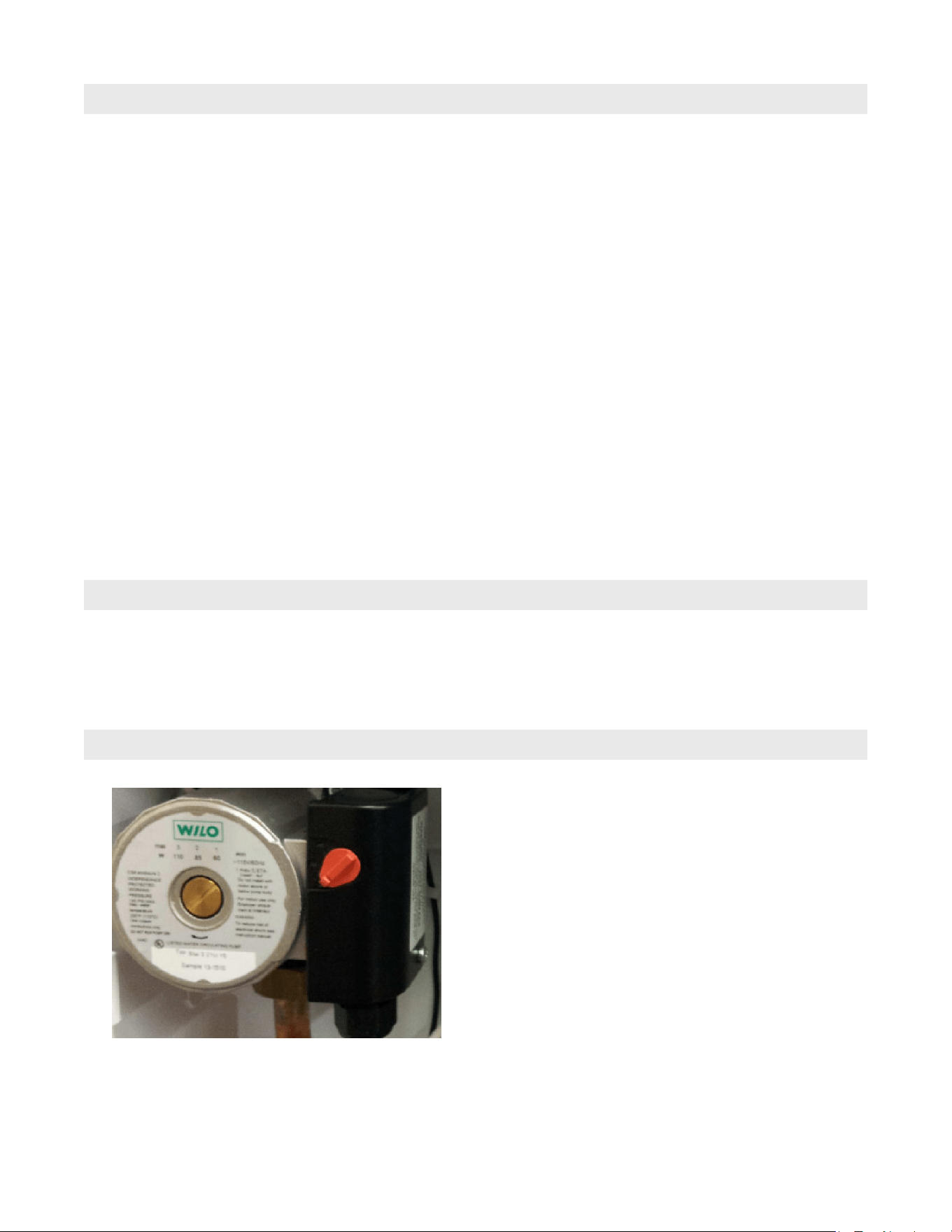
Circulating Pump Information
This electric boiler is equipped with a Wilo Star S 21 U
15, 3 speed circulating pump. To determine the speed or
setting of the pump, confirm with system design completed
by others and or complete a pressure-loss calculation.
Refer to calculations of loop lengths to determine proper
speed. The pump will automatically operate based on a
thermostat call for heat. After the thermostat temperature
set point has been reached, the pump will continue to
circulate water as part of a post purge operation to push
heated water away from the heat exchanger.
This electric boiler is also equipped with an additional
pump relay. This will aid the installer if there is any need
to pipe the systems with a secondary circulating pump to
overcome pressure drop due to piping or hydronic tubing
design. This is commonly referred to as primary/secondary
applications described in the piping arrangement section.
8
5472 726 - 06
Vitotron 100 Electric Boiler Installation/Service
Plumbing Installation Guidelines
Instructions for the Installer
1. Remove outer screws at the bottom and at the top
of electric boiler and carefully open the front cover.
2. The electric boiler is wall hung and must be installed
in a vertical position where plumbing connections are
located at the bottom. Utilize key holes slots to hang
the electric boiler. Refer to diagram on clearances
(page 5).
3. The electric boiler is provided with a e in. air vent
located on top of the heat exchanger. It is designed to
collect and remove air. Ensure plastic drain tubing
remains in place and exits the electric boiler in the
lower right corner.
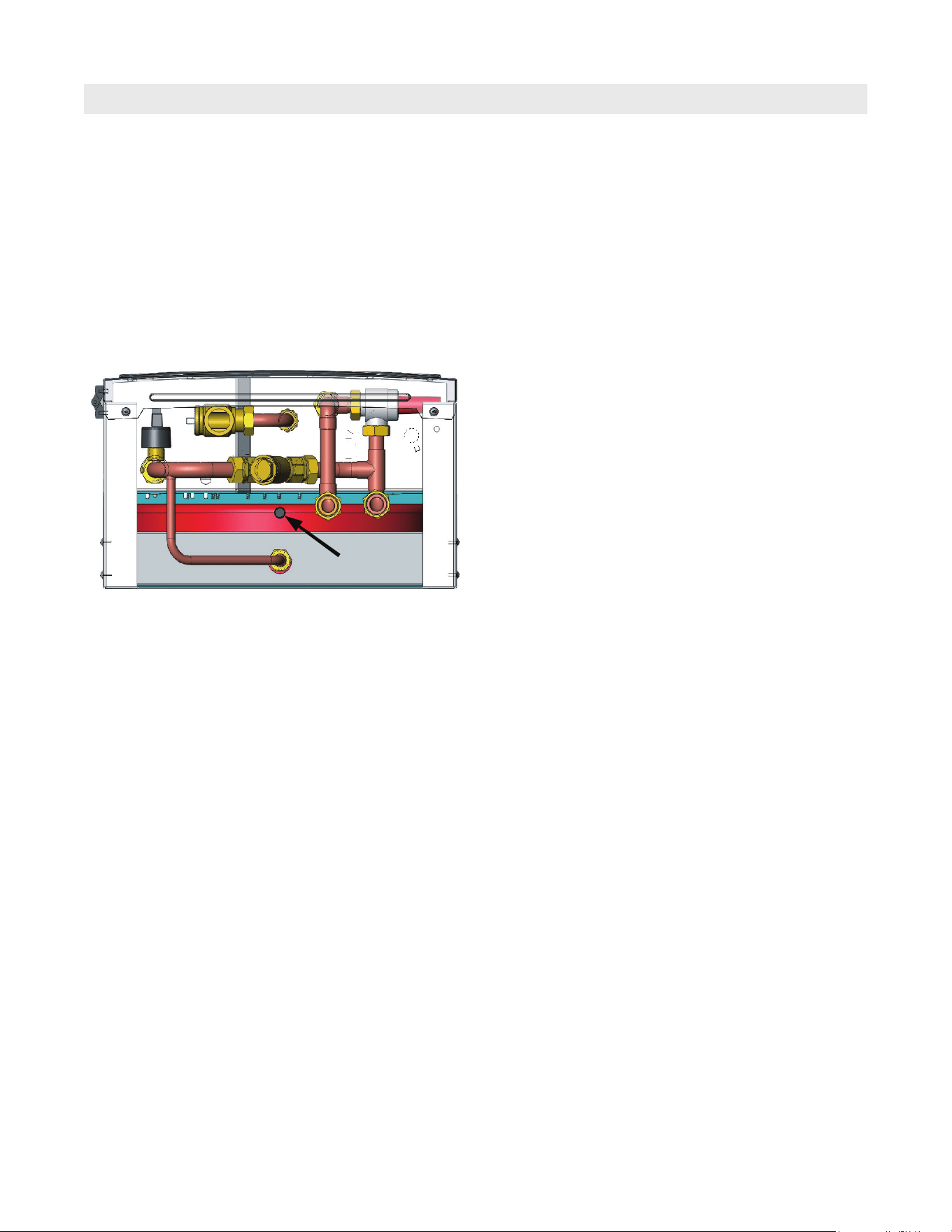
4. The electric boiler is equipped with a pre-charged flat
expansion tank located on the back housing of the
electric boiler. Expansion tank has a Schrader valve,
which location as shown in the diagram to the left.
This diagram presents the bottom view of the electric
boiler. Access to the valve is only from the bottom of
the electric boiler. From there it can be connected to
any pressure gauge to check the pressure or pump to
refill the air inside the tank.
5. The electric boiler is equipped with an ASME
approved 30 psi automatic safety pressure relief
valve. Install the necessary length of c in. copper
piping from the relief valve to within 6 in. of the floor
to prevent personal injury or water damage to
surrounding area.
6. Observe inlet return piping (blue label) and outlet
supply piping (red lable) connections. Install
shutoff valves below inlet and outlet connections
before plumbing the electric boiler to the hydronic
heating system.
DO NOT reverse these connections to the supply and
return manifolds. Optional temperature or pressure
gauges can be installed below the electric boiler if
desired.
7. Install boiler drain valve(s) as necessary to aid in
filling, purging and draining of unit and the related
system components.
8. Water supply feed or pressure reducing valve to
be installed to comply with local building codes.
Local codes may require a back flow preventer when
installing a fixed domestic water supply line to the
electric boiler.
Schrader Valve
9
5472 726 - 06
Vitotron 100 Electric Boiler Installation/Service
Plumbing Installation Guidelines (continued)
Instructions for the Installer
9. When possible, fill the electric boiler and hydronic
system with treated water. (i.e. soft or distilled
water) This will substantially extend the life of the
heating elements and reduce sediment buildup.
10. Freeze protection additives can be added. Only use
propylene glycol type freeze protection products for
hydronic heating systems that are non-toxic and
corrosion resistant.
The propylene glycol mix shall not exceed 50%, by
volume. 1 Under no circumstance should methanol
or ethylene glycol (automobile antifreeze) be added
to the electric boiler system as this may damage
internal components.
11. Insure purging of all air throughout electric boiler
system and related components.
12. This electric boiler requires a minimum
pressure of 7 psi in order to operate. Pressure levels
for hydronic systems typically are above the pre-
charged expansion tank pressure level (12 psi), if
required adjust the precharge of the expansion tank to
match system pressure requirements.
If additional pressure gauges are installed verify
reading.
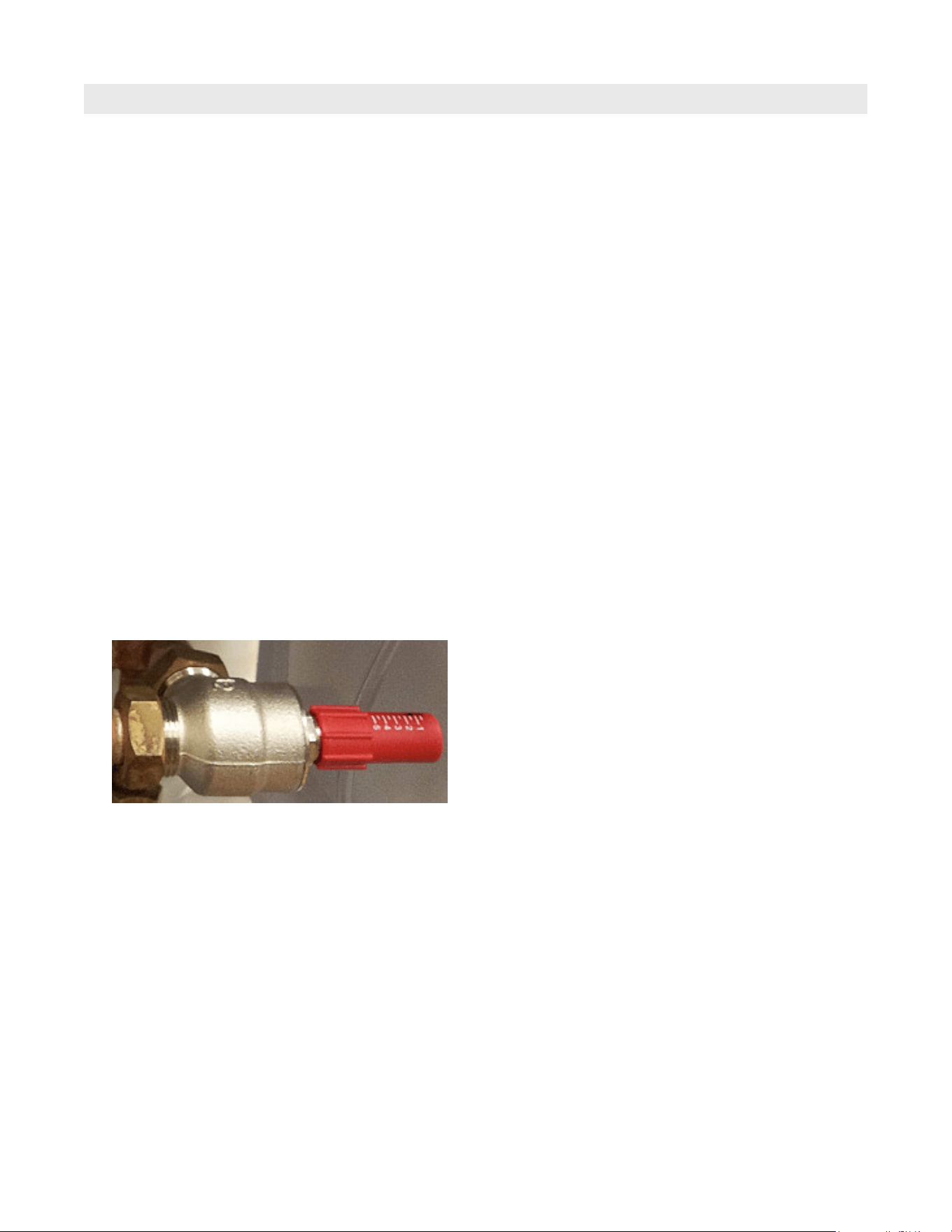
13. The electric boiler is equipped with a pressure
differential bypass valve. This allows the minimum
flow rate to pass through the electric boiler when all
zone valves are closed. The valve will also help
reduce noise issues upon closing of zone valves or
actuators.
To adjust:
Turn differential bypass valve clockwise until it stops.
Turn on all heating zones and let them heat for a
couple of minutes.
Caution! Piping can get hot quickly upon opening
the valve. Slowly open the bypass valve by turning
in a counter clock wise direction.
Stop turning once an increase in temperature is felt
on the outlet side of the valve. This is referred to the
tipping point. After reaching the tipping point continue
to turn the valve one complete turn. The valve is now
set to bypass excess flow as zone valves close.
Set the thermostats to normal set temperatures.
14. Proceed to the Electrical Installation.
10
5472 726 - 06
Vitotron 100 Electric Boiler Installation/Service
Electrical Installation
Instructions for the Installer
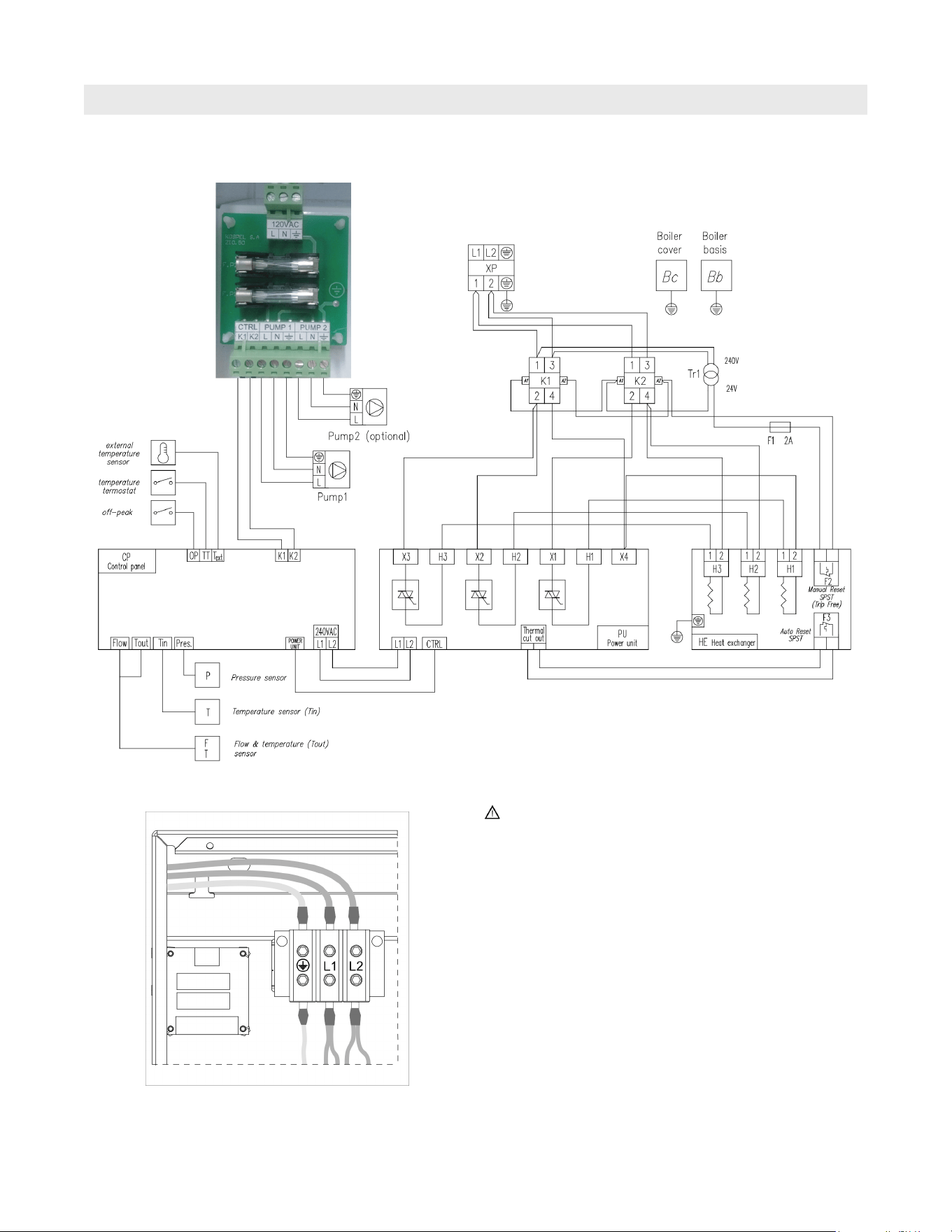
For heating element power supply connections, use
wires suitable for at least 167°F (75°C) and sized for
the amperage load specified on page 4 of this manual.
1. All electrical work should be completed in accordance
to local or state electrical and building codes.
2. This electric boiler must be electrically grounded in
accordance with National Electrical Code ANSI/
NFPA70, or local codes.
3. This electric heating elements operate with 240VAC
single phase electrical power source. A separate
120VAC power supply is required for the internal
pump and connected circulating pump
4. Connect the electric boiler to the electrical service
using 1 COPPER WIRE ONLY. Tighten connections
by using a 3/16 in. Hex key tool. Conform to local
electrical codes for correct sizing of electrical breakers
and size of electric conductor wires. Refer to electric
boiler nameplate for current and kW ratings. Local
electric codes may require an electrical disconnect.
Electrical Wiring Diagram
11
5472 726 - 06
Vitotron 100 Electric Boiler Installation/Service
Electrical Installation (continued)
Instructions for the Installer
5. The circulating pump requires a separate 120VAC,
15 amp electrical circuit. Utilize b in. electrical
knockout as marked on the left side of cabinet to
access circulating pump wiring connections inside
electric boiler. Do not combine the high voltage power
for circulating pump with any thermostat or off peak
low voltage wires.
An optional secondary pump can be installed in the
system for hydronic applications plumbed with multiple
circulators and or primary/secondary applications.
Utilize the Pump 2 connections to operate the
secondary pump. The secondary pump will
automatically turn on upon closure of thermostat
connections on control panel. Spare fuses are taped
into the inside cover.
Fuses specified as:
Time-delay Glass Fuse 6.3 x 32 mm 2A.
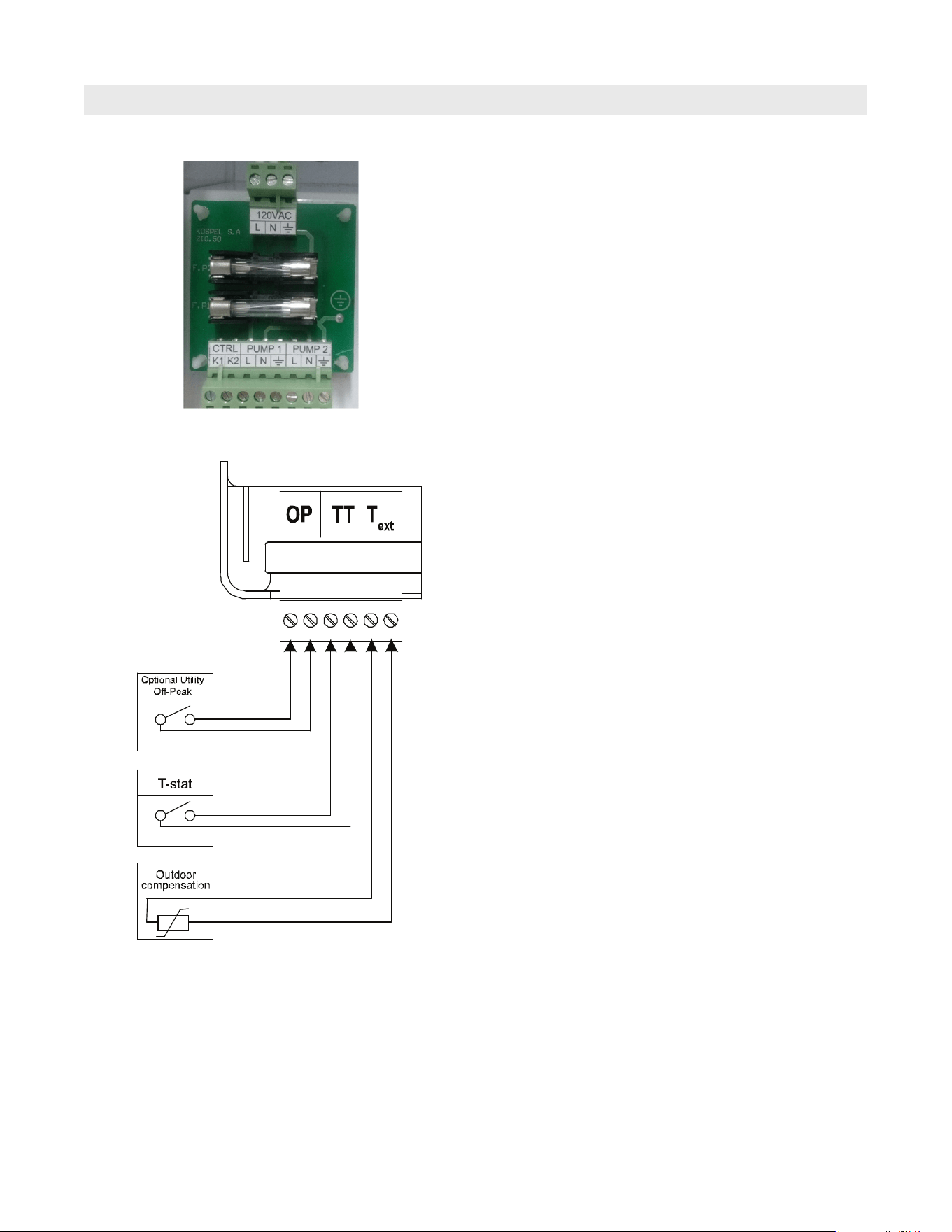
6. Thermostat - This electric boiler can be signaled
to turn on from a standard two wire thermostat,
end switches of an actuating valve or a zone control
panel. These connections should all be voltage
free (dry contact). Extend wires from thermostat
to TT connections on control panel using 2 x 18
gauge wires. Utilize b” electrical knockout to left side
of control panel to gain entrance to this connection.
Install thermostat in a location where it will not be
influenced by other heat sources.
7. Off peak control (optional) -This electric boiler is
equipped with a connection (normally closed) to
receive a utility signal for off peak denoted by OP on
the control board. Ensure the interconnection
from is voltage free (dry contact).
Consult with local utility on questions with off-peak
installations. Keep blue/white jumper wire in place if
not connected.
8. Weather Compensated - The electric boiler can utilize
an outdoor sensor for outdoor compensation
capability. Install the outdoor sensor preferably on the
north side of the building. Keep the outdoor sensor
away from any sources of heat.
Refer to Advanced Settings on page 14 to set proper
heat curve. If no outdoor sensor is wired to the T
ext
terminals on the control panel, the electric boiler will
operate in fixed setpoint.
9. Final check. Verify all electrical connections are tight.
Loose connections can cause premature failures of
electrical components. Once you have finished the
above procedures and before starting the electric
boiler, familiarize yourself with the control buttons
and indicators on the control panel in the following
page.
10. Re-fasten the screws on bottom (2) and top (1) to
hold front door in place.
12
5472 726 - 06
Vitotron 100 Electric Boiler Installation/Service
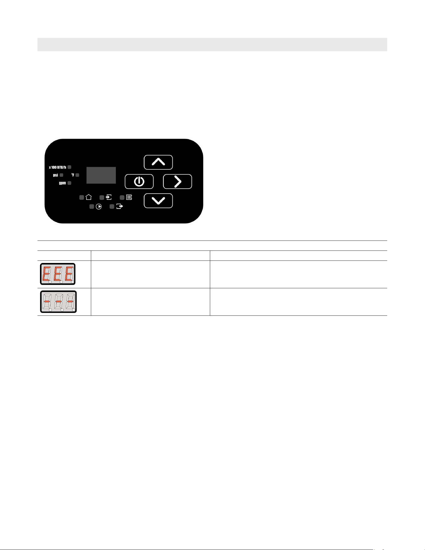
Control Panel
Instructions for the User
The control panel allows the user to identify flow rate
(GPM),the inlet and outlet operating temperatures and
the Btu/h of the electric boiler at any given time. It will
also aid in identifying any faults, which may occur, by
displaying the fault codes.
Indicators
X 100 Btu/h = British thermal units per hour
psi = Pounds/Square Inch, pressure level
gpm= Gallons/minute or Flow rate
F° = Temperature (Fahrenheit)
Buttons
9= Power
5/6 = Up and down selection
4= Scroll option
Failures indication
Indicator Status Details
EEE Message on electronic display Data record error
Parameter out of range or a failed temperature sensor
The control panel consists of two working areas: the
signaling area and control buttons. The user can select
the following working modes: winter mode (heating mode)
or summer mode (stand-by mode). Utilize the push button
arrows to scroll through the different working parameters
of the electric boiler. The control panel will automatically
switch to main view if no buttons are pressed within 1
minute.
13
5472 726 - 06
Vitotron 100 Electric Boiler Installation/Service
Winter Mode (Heating Mode)
Instructions for the User
Heating Mode / Initial Start-Up
3. If 120VAC power is connected to the circulating
pump, turn control panel on 9 and utilize push
buttons to scroll to psi indicator. Disconnect
thermostat wiring connection below control panel.
This will ensure electric boiler will not operate. If
pressure is below the 7 psi level the circulating pump
indicator will blink. Verify pressure (psi) reading on
control panel to achieve desired pressure levels.
Typical pressure readings should be slightly above
the 12 psi expansion tank setting or higher depending
on application (15-20 psi recommended).
4. For testing, turn the thermostat above the room
temperature reading. This will turn the electric boiler
on. After testing return the thermostat to a comfort
setting.
5. To immediately return to the main viewing mode,
press the 9 button. If no buttons are pressed the
control will automatically return to the main viewing
mode after one minute.
1. To set in the heating mode press the power button 9.
The indicators will show the current working mode
of the electric boiler.
2. Set the supply water temperature (SWT) set point.
Utilize the right arrow4push button to scroll
through working parameters of the electric boiler.
Highlight the SWT symbol r and utilize the up and
down arrows 5/6 to select the temperature that
meets the hydronic system heating application. The
supply water temperature can be set between
85° - 140°F. Notice the °F symbol will light up at the
same time when changing temperature.
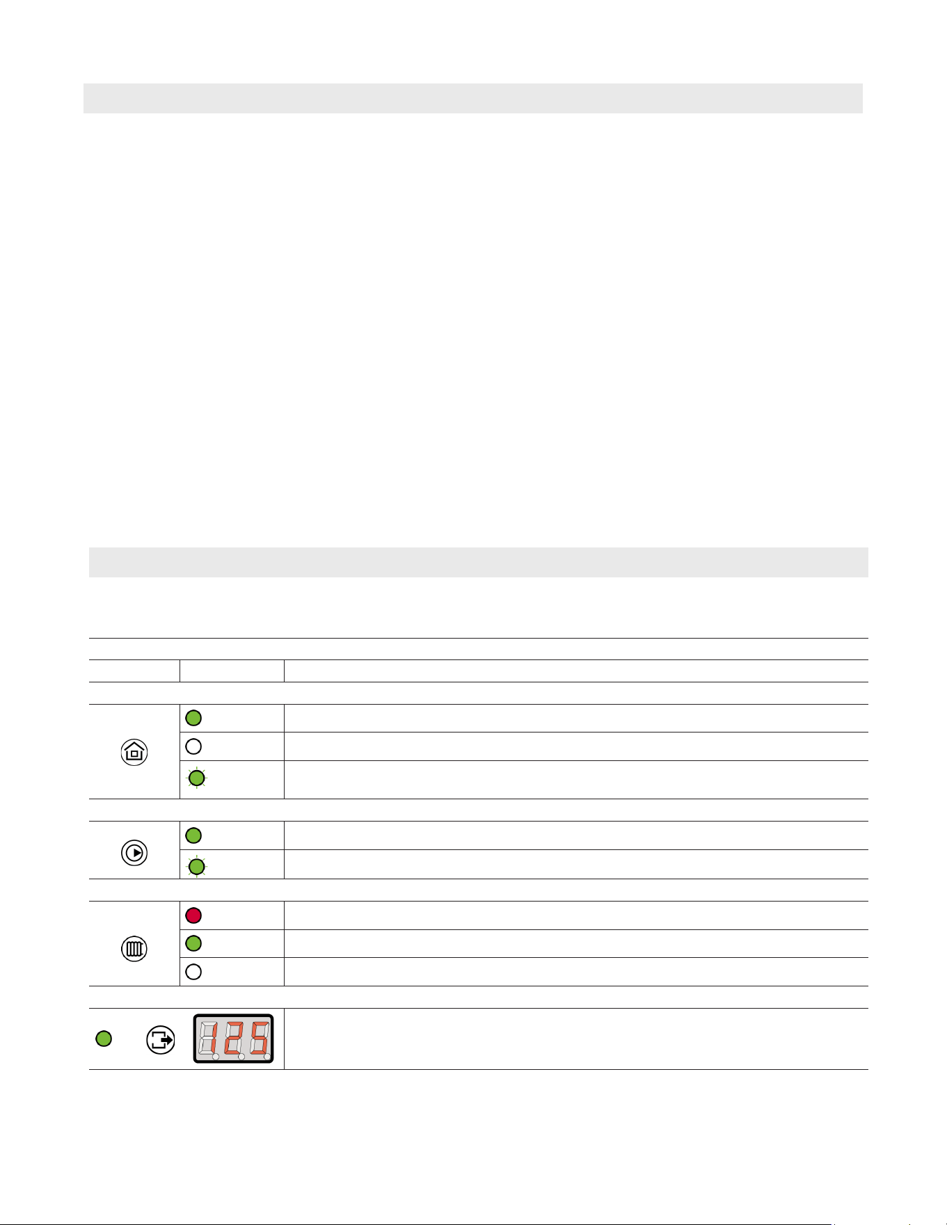
To set in the heating mode press the power 9 button. The indicators will show the current parameters of the electric
boiler (see control panel).
MAIN VIEW
INDICATOR STATUS DETAILS
Heating Status
on
Thermostat is calling for heat
off
Room set temperature has been reached - no call for heating
blinks
Off Peak load control or master appliance mode.
Outdoor temperature reached a thermal cut - off value (see parameter 5 in advanced settings).
Circulating Pump Indicator
on
Pump is active, proper flow rate of water has been reached
blinks
Lack of water flow or insufficient flow of water - heating elements off
Supply Water Temperature
red light
Electric boiler is in heating mode
green light
Supply water temperature has been reached in the electric boiler
off
Heating is off
Outlet Temperature
°F
Temperature on the outlet of the electric boiler
14
5472 726 - 06
Vitotron 100 Electric Boiler Installation/Service
Winter Mode (Heating Mode) (continued)
Instructions for the User
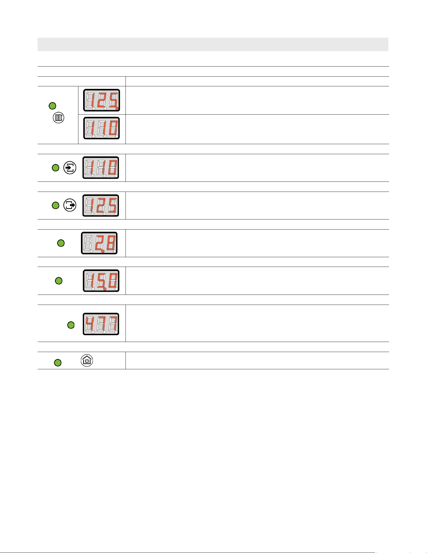
SUPPLY WATER TEMPERATURE VIEW
INDICATOR DETAILS
°F
The LED in the first location on the display indicates automatic setting, according to the
heating curve and offset (see parameters 4 and 5 in advanced settings). This is active
only when the outdoor sensor is wired to Text terminals on control panel.
Manual setting (see parameter 4 in advanced settings), outlet temperature can be set
manually in range 85 - 140°F.
Use buttons 5and6 to change the parameter.
INLET TEMPERATURE VIEW
°F
Inlet temperature
OUTLET TEMPERATURE VIEW
°F
Outlet temperature
FLOW VIEW
gpm
Flow rate [gallons/min.]
PRESSURE VIEW
psi
Pressure level [pounds/square inch]
ENERGY CONSUMPTION VIEW
X100
BTU/h
Current energy consumption [BTU/h]
OUTDOOR TEMPERATURE VIEW
°F
Outdoor temperature. In case of lack of outdoor temperature sensor, preview is not available

15
5472 726 - 06
Vitotron 100 Electric Boiler Installation/Service
Winter Mode (Heating Mode) (continued)
Instructions for the User
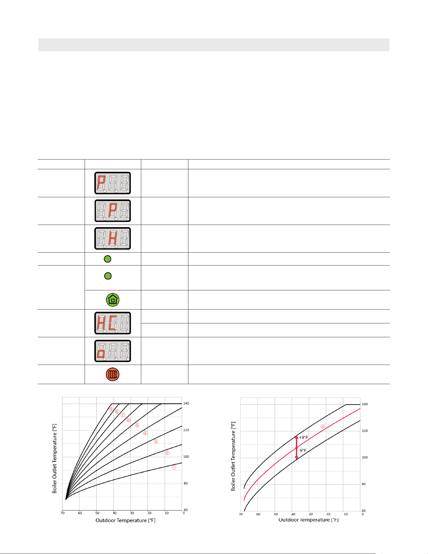
To use the outdoor compensation option refer to outdoor
compensation graphs on page 14. The outlet temperature
is adjusted depending on the outdoor temperature.
For example, if it’s cold, the outlet temperature should
increase, but if outdoor temperature is warmer, the
outlet temperature should be adjusted lower. Outdoor
compensation option is based on heating curves (see
“Advanced Settings”).
User can choose from one of the 9 heating curves
available.
One method of selecting the correct curve is as follows.
The first step is to determine the temperature on the
horizontal axis (outside temperature from 0°F to 70°F),
which represents a common outdoor temperature during
which the system is operating, for example 30°F.
Then run in a straight line up to intersect a curve
corresponding to the desired boiler supply temperature on
the vertical axis for the hydronic system at that outdoor
temperature in the hydronic system. In our example, at
30°F outside the building we want to have 115°F for the
heating (see the diagram on page 14), so we get exactly
the heating curve defined as 4. If the intersection point of
selected temperatures is not placed on the curve, we
choose the closest. For example, 30°F outdoor
temperature, and the desired 110°F for hydronic system
can lead to a selection of curve 3 or 4. It should be
checked periodically, whether the choice was correct,
if not - another curve should be used.
The heating curve offset
If in wide range of outdoor temperatures the electric boiler
is not able to maintain the desired indoor temperature (it’s
too cold or too warm), the heating curve chosen before
should be shifted (offset in range -9°F to +9°F available
in options on control panel). If the indoor temperature is
too warm - the heating curve should be shifted down and
vice versa (refer to the diagram on page 14).
Special start-up procedure (when the system is filled with
an antifreeze solution)
A flow rate reading error may occur if you start-up the
unit at low ambient temperature. This error may occur
because the physical properties of antifreeze solution.
If the indicator flickers and the cut-off valves are
opened you have to close OP and TT contacts which will
automatically start the special start-up procedure.
As a result, the medium will be warmed up to temperature
that enable you to read the flow rate correctly.
The duration of procedure depends on both the installation
capacity and the temperature inside the installation.
When a control panel display shows selected parameters
alternately and marks („-”, „--”, „---”) it means that
the procedure is started. The procedure will close
automatically and the unit will start normal operation once
the minimal flow rate is reached.
16
5472 726 - 06
Vitotron 100 Electric Boiler Installation/Service
Summer Mode (Stand-by Mode)
Instructions for the User
Do not shut off the power supply between heating
seasons. To set the electric boiler to summer or stand-by
mode press and hold 9 power button for 3 seconds.
When the control panel is switched to summer mode the
control panel is off and the stand-by mode indicator
remains blinking. In this mode the electric boiler is off but
the pump is activated every day for 15 minutes.
This summer mode protects the electric boiler and the
hydronic heating installation from being blocked and
silted up. The pump will run every day at the same time
when the electric boiler is switched to summer mode. For
example, if you turn the electric boiler to “stand-by” mode
at 6 p.m. the timer will activate the pump every day for
15 minutes starting at 6 p.m.
To set the electric boiler back to winter heating mode
press and hold power button 9 for 3 seconds.
Note: In summer mode, based on U.S. national electric
rates of $.10/kWh the cost of operating the
circulating pump for 15 minutes/day will equate to
approximate usage of $.08 / month on the highest
speed.
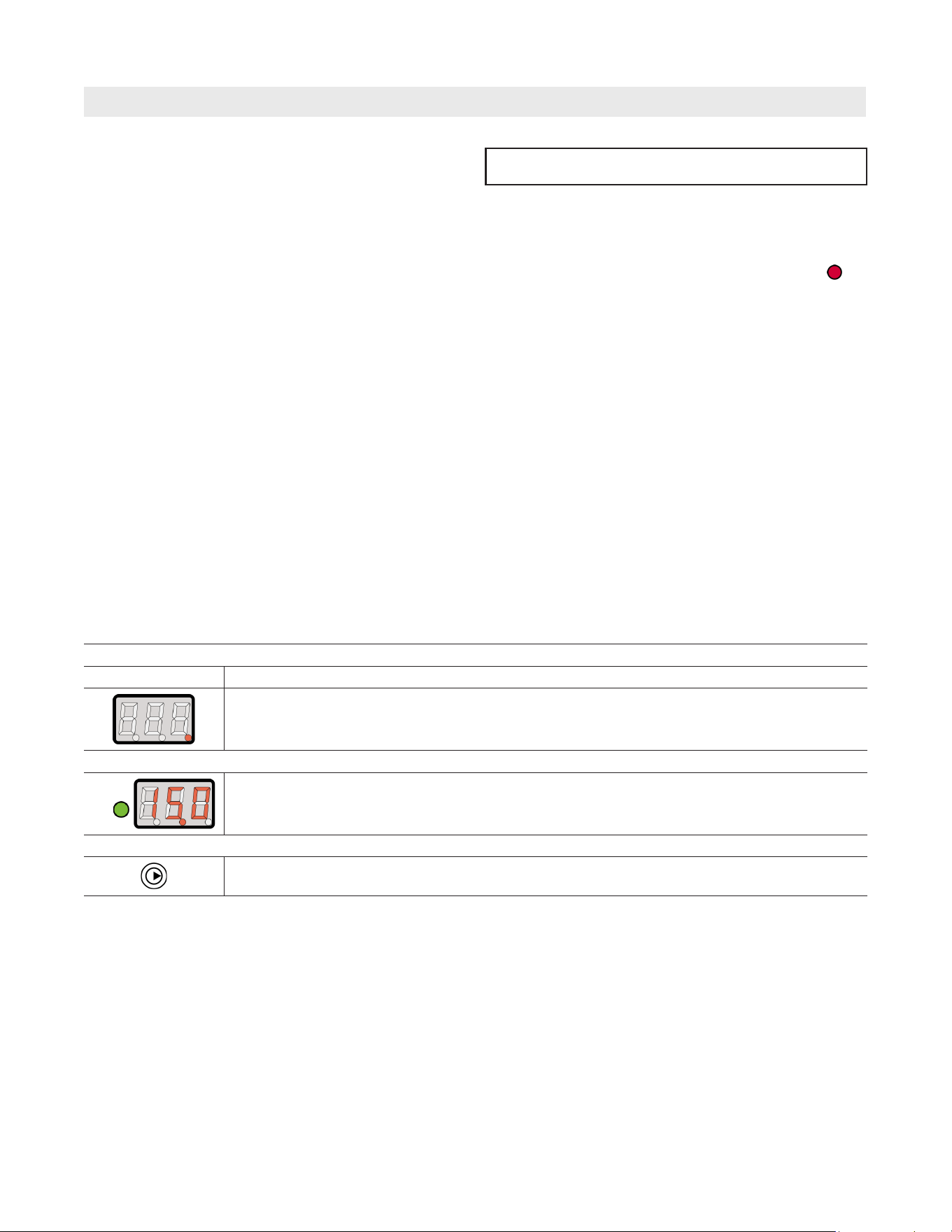
MODE VIEW
INDICATOR DETAILS
The control panel is off and the stand-by mode indicator (dot) blinks only.
PRESSURE VIEW
psi
Pressure level [pounds/square inch].
To check out the installation pressure press
STATUS PUMP VIEW
Circulation pump is active. In summer mode (heating elements turned off).
The circulating pump will operate for 15 minutes, once every 24 hours each day.
IMPORTANT
17
5472 726 - 06
Vitotron 100 Electric Boiler Installation/Service
Advanced Settings
Instructions for the User
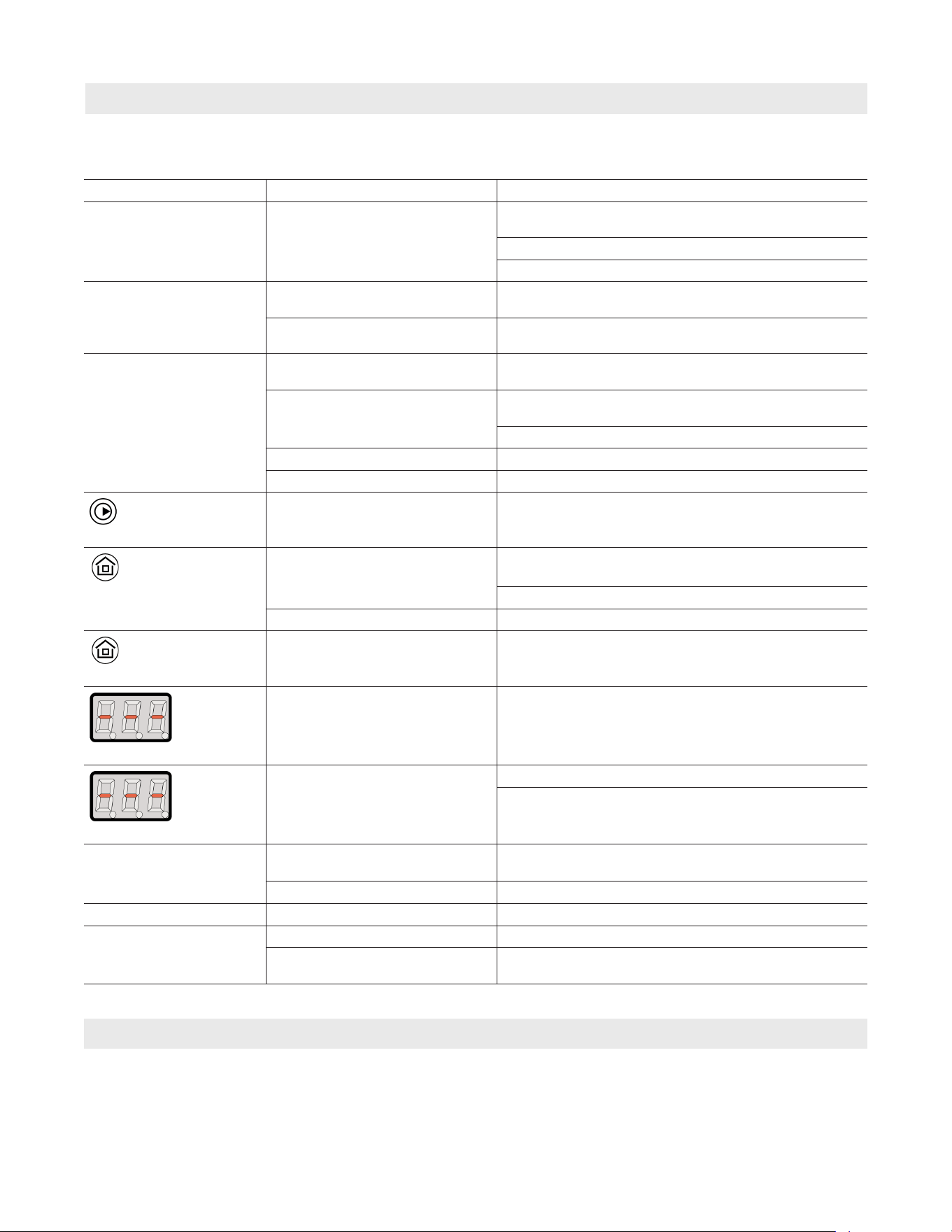
To enter advanced settings the control must first be put into
standby mode. Enter standby mode by pressing and holding
the power button 9 (Approx 3 seconds) until the display goes
blank, once the display goes blank, release the power button
9. Confirm the control is in standby mode by observing the
flashing red dot in the bottom right corner of the blank LCD
display.
With the display in standby mode, extended parameters can
be entered by pressing and holding the right arrow button
4, while still holding the right arrow button 4 press and
immediately release the power button 9. The display will
illuminate and display the first parameter group, you can now
release the right arrow button 4.
Parameters Indicator/display Status/value Details
1
4-14
Electric boiler - enter the power amount (kW) as indicated on
identification label.
This value is factory preset.
2
A/n
Working mode of pump – PA = (automatic), Pn (manual –
continuous duty of pump).
3
1, 2, 3 Maximum quantity of active heating elements.
4
psi
off/on
Installation pressure control
5
°F
30-70
Outside temperature above which electric boiler will not heat,
in case of electric boiler’s failure or lack of outside temperature
sensor, function is not active
off Function not active
6
1-9
Selection of heating curves (see diagram “Outdoor compensation”)
0
Manual setting of outlet temperature
7
-9 + 9
Offset of heating curve characteristic [°F]
(see diagram “Offset for outdoor compensation”)
8
Electric boilers working time counter in hours
Offset for outdoor compensation
Outdoor compensation
To make changes to a parameter use the up and down
arrows 5,6 and select the desired value. To advance to
the next parameter press the right arrow button 4. Once
you have finished setting the parameters, press and hold the
power button 9 until the display goes back to stand by mode
(blank with intermittent red dot). The settings have now been
changed and you can press the power button 9 to turn the
boiler back on.
18
5472 726 - 06
Vitotron 100 Electric Boiler Installation/Service
Troubleshooting
Instructions for the User
Failure to service properly may lead to further damage to
components.
Symptom Reason Action
All indicators on control
panel are OFF
No power to electric boiler Check for 240 VAC on electric boiler main connection
terminals
Reset manual safety high limit
Contact authorized service person
“PSI” indicator blinks Insufficient pressure below 7 psi Switch the controller to pressure view and increase
system pressure above the minimum required 7 psi level.
Pressure sensor failure Switch the controller to pressure view, if display
shows - - Contact authorized service person
“GPM” indicator blinks Pump is blocked Unblock the pump-unscrew the screw on pump
housing and move the pump rotor manually
Heat does not circulate through
the electric boiler – electric boiler
is blocked
Air bubble is caught in system, purge the installation,
pump and electric boiler
Check 1 amp fuse on control panel
Failure of pump or flow sensor Check power supply for circulating pump
a failure of pump or flow sensor Contact an authorized service or the seller
Circulator indicator blinks
Lack of water flow - 2.1 GPM min Adjust flow characteristics as needed
“Heating status” is off
No thermostat connection Insure thermostat is calling for heat and is above
ambient temperature set point
Verify connections on thermostat
Failure of control board Check fuse on control panel glass fuse 6.3 x 32 mm 2A
“Heating status” blinks
Off Peak signal = no heat Electric utility off peak control
and “Inlet temp.” blinks
A failure of inlet temperature
sensor, electric boiler in failure
condition
Check connection or replace thermistor sensor
and “Outlet temp.” blinks
A failure of outlet temperature
sensor or loose connection
Check connections
Replace HC-DN 15 sensor
Electric boiler does not
heat
Failure of cylinder temperature
sensor
Contact authorized service person for replacement of
cylinder temperature sensor or thermostat
A failure of control panel Contact authorized service person
EEE message on display Data record error Contact authorized service person
Insufficient heat output Heating elements Check for resistance on elements
Control panel set up failure Insure control panel is set up for correct kW and
number of heating elements through advanced settings
Care and Maintenance
1. In order to protect flow sensor located within the
electric boiler, it is imperative that the pre-installed
magnetic filter is removed and cleaned at least
annually. Failure to clean out this filter could increase
contamination of the electric boiler by system residue.
1 Do not attempt to service this electric boiler unless
you have been trained in all aspects of its functionality and
methods to repair.
2. Periodically check system pressure.
Contact authorized service person to make
adjustments only.
19
5472 726 - 06
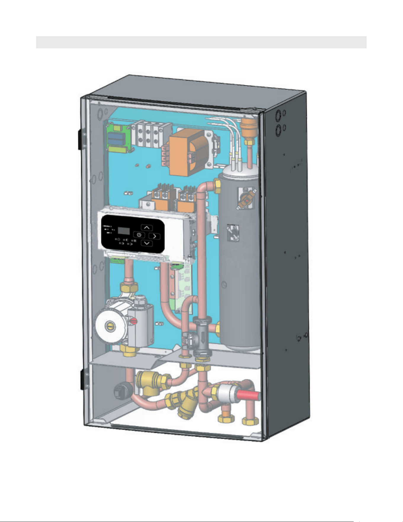
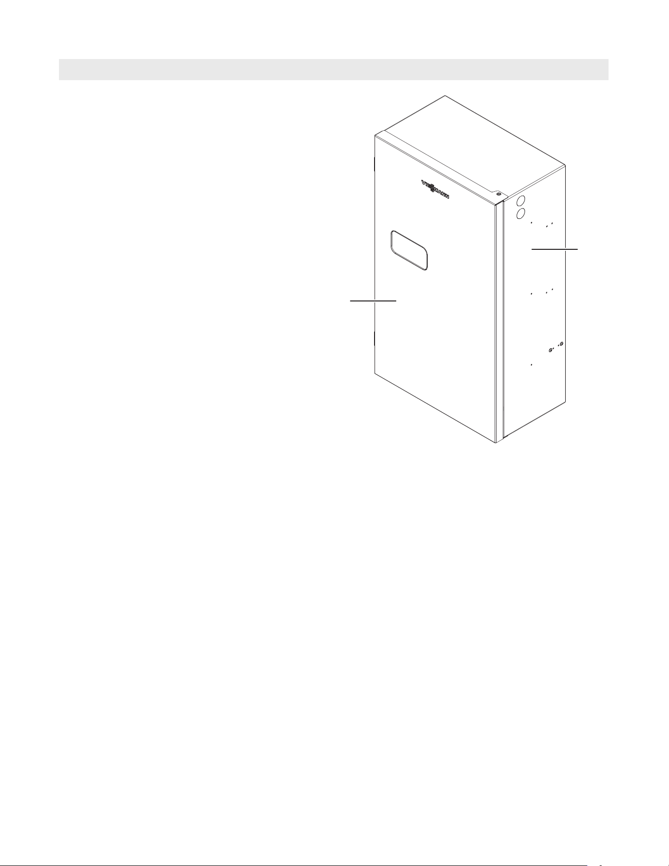
Vitotron 100 Electric Boiler Installation/Service
General View of the Electric Boiler
Instructions for the User
20
5472 726 - 06
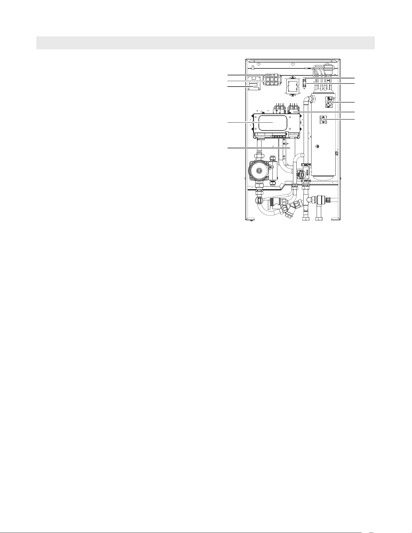
Vitotron 100 Electric Boiler Installation/Service
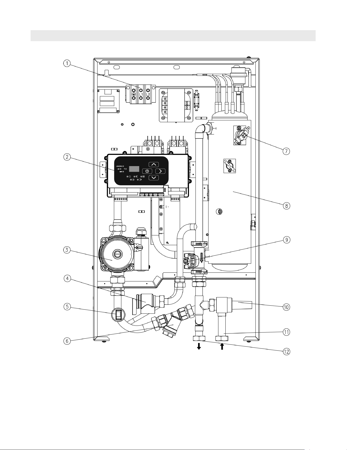
Part List
Instructions for the User
Legend
1 Heating Element Power Supply Terminals
2 Control Panel
3 Pump
4 Pressure Relief Valve
5 Pressure Sensor
6 Magnetic Filter
7 Manual Reset High Limit Device
8 Heating Element
9 Flow and Outlet Temperature Sensor
qP By-Pass Valve
qQ Water Inlet
qW Water Outlet
21
5472 726 - 06
Vitotron 100 Electric Boiler Installation/Service
Instructions for the User
Boiler Model No. Serial No.
VLN2-04 7547318
VLN2-06 7547370
VLN2-08 7547373
VLN2-12 7547875
VLN2-14.4 7547898
Ordering Parts:
Please provide Serial Number when ordering
replacement parts. Order replacement
components from your Viessmann distributor.
Jacketing
1001 CASE SET, BACK VLN2
1002 FRONT COVER VLN2
Part List
1001
1002
22
5472 726 - 06
Vitotron 100 Electric Boiler Installation/Service
Boiler Model No. Serial No.
VLN2-04 7547318
VLN2-06 7547370
VLN2-08 7547373
VLN2-12 7547875
VLN2-14.4 7547898
Ordering Parts:
Please provide Serial Number when ordering
replacement parts. Order replacement
components from your Viessmann distributor.
Electronic Components
2001 POWER BOARD, WITHOUT CONNECTION VLN2
2002 CONTROL PANEL PSK.P7 VLN2
2003 BOARD, ZIO 50 VLN2
2004 THERMAL SAFETY, 60T-X25 VLN2
2005 CONTACTOR (HARTLAND) 40A 2P VLN2
2006 TRANSFORMER, (TEC) 24V VLN2
2007 FUSE SOCKET VLN2
2008 FUSE, 6.3X32MM 2A VLN2
2009 ELECTRICAL CONNECTOR, VC05-0013 VLN2
2010 HOLDER, KU-2 GRAY VLN2
2011 THERMAL CUT-OUT, 36T AUTO RESET VLN2
2012 POWER BOARD, W/ CONNECTION VLN2
*1
2013 RETURN TEMP SENSOR NTC VLN2
*1
*1
Not Shown
Part List
Instructions for the User
2003
2009
2010
2002
2001
2007
2008
2004
2005
2011
23
5472 726 - 06
Vitotron 100 Electric Boiler Installation/Service
Boiler Model No. Serial No.
VLN2-04 7547318
VLN2-06 7547370
VLN2-08 7547373
VLN2-12 7547875
VLN2-14.4 7547898
Ordering Parts:
Please provide Serial Number when ordering
replacement parts. Order replacement
components from your Viessmann distributor.
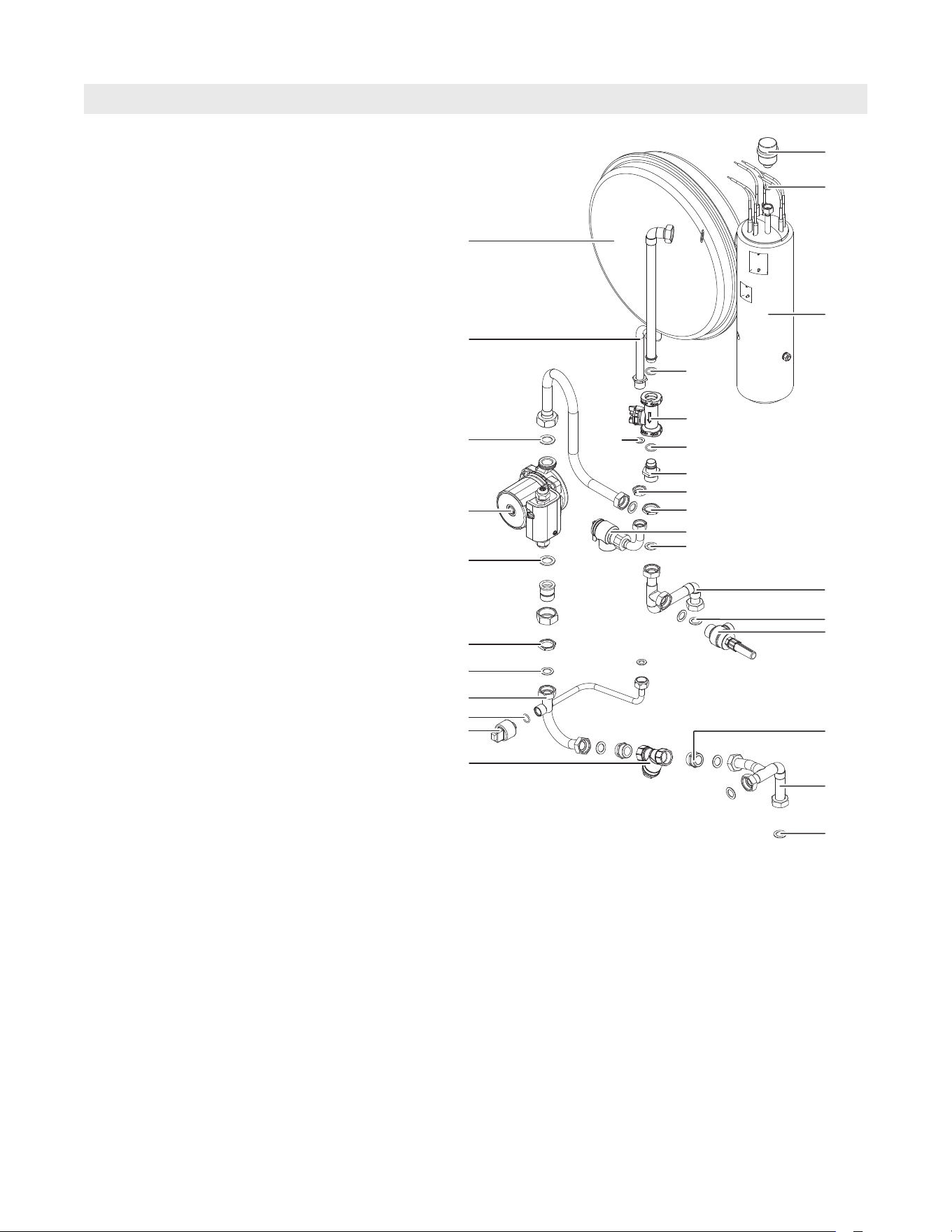
Hydraulic Components
3001 AUTOMATIC AIR-VENT VALVE VLN2
3002 GASKET 1.5X8X14.8 VLN2
3003 GASKET 1.5 X 11.7 X 18.2 VLN2
3004 GASKET 2 X 20 X 30 VLN2
3005 EXPANSION VESSEL 6L G1/2” VLN2
3006 GASKET 1.5 X 16 X 24 VLN2
3007 PRESSURE TRANSDUCER VLN2
3008 DIFFERENTIAL PRESS. VALVE 3/4” VLN2
3009 O-RING SEAL GASKET 70NBR VLN2
3010 MAGNETIC FILTER 3/4” VLN2
3011 FLOW TEMPERATURE SENSOR DN15 VLN2
3012 HEATING BOX 240V VLN2
3013 RETURN, CONNECTION PIPE VLN2
3014 PUMP CONNECTION PIPE, INTERNAL VLN2
3015 FLOW CONNECTION I VLN2
3016 FLOW CONNECTION II VLN2
3017 NIPPLE, 3/4” VLN2
3018 NUT, 1/2” VLN2
3019 NUT, G3/4” VLN2
3020 CONNECTION PIPE VLN2
3021 BUSHING VLN2
3022 CIRC PUMP (WILO) STAR S21U-15 VLN2
3023 O-RING 14 X 2 VLN2
3024 SAFETY VALVE W/CONNECTION PIPE VLN2
Part List
Instructions for the User
3001
3022
3002
3012
3004
3007
3004
3019
3006
3005
3015
3010
3009
3011
3009
3020
3003
3018
3019
3024
3006
3023
3013
3014
3006
3017
3008
3006
3016
5472 726 - 06
Vitotron 100 Electric Boiler Installation/Service
Technical information subject to change without notice.
Printed on environmentally friendly
(recycled and recyclable) paper.
Scan for
digital copy
of this
document