
1
Installation and
Operating Instructions
ELECTRIC HOT WATER
&
STEAM BOILERS
PCW – 1 Series
2
FOR YOUR SAFETY
This manual supplies information on the application, installation and operation of Lochinvar
Electric Hot Water & Steam Boilers. Review all application and installation procedures
completely before proceeding with the installation. Consult the Lochinvar Boilers’ Factory or
local Factory Representative with any problems or questions regarding this equipment.
Experience has shown that improper installation causes most operation problems.
WARNING
Improper installation, adjustment, alteration, service or maintenance can cause injury or
property damage. Read this manual thoroughly and follow the instructions herein. The
Lochinvar shall be installed according to the procedures detailed in this manual, or the Lochinvar
Limited Warranty may be voided. The installation must conform to the requirements of the
local jurisdiction having authority, and to the latest edition of the National Fuel Gas Code, ANSI
Z223.1. Any modifications to the boiler or its gas / oil controls may void the warranty. If field
installation requires modifications, consult either the local Lochinvar’ Representative or the
Factory.
RETAIN THESE INSTRUCTIONS NEAR THE EQUIPMENT FOR READY REFERENCE
Installation and Operating Instructions
ELECTRIC HOT WATER & STEAM BOILERS
PCW – 1 Series

3
TABLE OF CONTENTS
i Title page ............................................................... 1
ii Introduction ........................................................... 2
iii Table of Contents ................................................... 3
1.0 GENERAL INFORMATION
1.1 Introduction ........................................................ 4
1.2 Local Regulations ................................................ 4
1.3 Recommendations .............................................. 4
1.3.1 Preventative Maintenance .............................. 4
1.3.2 Water Treatment ............................................. 4
2.0. STORAGE & HANDLING
2.1 Receiving ............................................................. 5
2.2 Storage ................................................................ 5
2.3 Uncrating ............................................................. 5
2.4 Placement ........................................................... 5
Figure 1 - Minimum Clearance ................................. 6
3.0 INSTALLATION
3.1 Piping Connections ............................................. 7
3.2 Electrical Connections ......................................... 7
3.2.1 Power Feed Wiring .......................................... 7
3.2.2 Grounding Conductors ..................................... 7
3.2.3 Control Wiring ................................................. 8
3.3 Filling the System ................................................ 8
4.0 PRE-STARTUP INSPECTION
4.1 Minimum Equipment for Startup ....................... 8
4.2 Mechanical System Checks ................................. 8
4.2.1 Plumbing Connections ..................................... 8
4.2.2 Feedpump / Circ Pumps .................................. 9
4.2.3 System Flush .................................................... 9
4.2.4 Valves ............................................................... 9
4.3 Electrical System Checks ..................................... 9
4.4 Heating Elements .............................................. 10
4.5 Inspection Power / Voltage .............................. 10
5.0 STARTUP INSTRUCTIONS
5.1 Control Settings ................................................ 11
5.1.1 Controller ....................................................... 11
5.1.2 High Limit ....................................................... 11
5.1.3 Low Water Cutoffs ......................................... 11
5.1.4 Low Limit Sensors .......................................... 11
5.2 Operating Instructions ...................................... 11
5.2.2 Electric Door Interlocks .................................. 12
5.2.4 120-Volt Power Source .................................. 12
5.2.6 Alarm and Reset Circuits ................................ 12
5.2.7 Sequencing of Elements Circuits ................... 12
6.0 SEQUENCE OF OPERATION
6.1 Activation of Heating Element Circuits ............ 12
6.1.1 Contactors ...................................................... 12
6.1.2 Fuses ............................................................... 13
6.2 Sequencing Controls ......................................... 13
6.2.1 Staged Control Circuit .................................... 13
6.2.2 Proportional Step Controls ............................ 13
6.2.2.1 Step Control Sequence ............................... 13
6.2.2.2 Progressive Sequence
Step Controls ........................................................... 13
6.2.2.3 Linear Sequence Step
Controls ................................................................... 13
6.2.3 Recycle Feature .............................................. 13
6.2.4 Manual Toggle Switches ................................ 14
6.2.5 Preheat Switch ............................................... 14
7.0 OPERATIONAL TESTING
7.1 Standard Controls ............................................. 14
7.1.1 135-ohm Controllers ...................................... 14
7.1.2 Solid State Controls ........................................ 14
7.2 Outdoor Reset Controls .................................... 15
7.2.1 135-ohm Type Outdoor
Reset Controller ...................................................... 15
Table 1 – Setting the Temperature
Controller................................................................. 15
7.2.2 Solid State Dual Input
Reset Controls ......................................................... 15
8.0 PREVENTATIVE MAINTENANCE
8.1 General ............................................................. 16
8.2 Water Treatment ............................................. 16
8.3 Electrical System Maintenance......................... 16
8.4 Boiler Mechanical System
Maintenance ........................................................... 17
8.5 Element Replacement Procedure .................... 18
Table 2 – Feedwater / Boiler
Water Properties ................................................... 18
8.6 Typical Preventative
Maintenance List ..................................................... 19

4
1.0 GENERAL INFORMATION
1.1 Introduction
LOCHINVAR has made a commitment to product improvement and follows a continuing
quest for the highest standards of product performance. In pursuing this policy of
continuous development of products, the manufacturer reserves the right to vary any
details in this manual without notice.
The instructions contained in this manual are intended as a guide only and do not
supplant any National, State or Local Codes.
This unit must be installed in accordance with those installation regulations in force in
the local area where the installation is to be made. These shall be carefully followed in
all cases. Authorities having jurisdiction shall be consulted before installation is made.
This Electric Hot Water / Steam Boiler and Water Heater Operation and Maintenance
Manual present information that will help to properly operate and care for the
equipment. Study the contents carefully. The unit will provide good service and
continued operation if proper operating and maintenance instructions are followed.
The standard Limited Warranty is not applicable with equipment not installed or
operated in accordance with these procedures.
The boilers are designed and engineered to provide excellent service and to give long
life on the job. Although the unit and its components afford a high degree of protection
and safety, operation of the equipment is not be considered free from hazards inherent
in the handling of electricity and pressurized hot water or steam.
Pay close attention to WARNINGS and CAUTIONS as these present situations of
potential hazard, and remember no amount of written instruction can replace
intelligent thinking and reasoning.
1.2 Local Regulations
Consult local building and safety codes before proceeding with work. The operation of
this equipment by the owner and his operating personnel must comply with all
requirements or regulations of the authorities having jurisdiction.
In the absence of such authorities, the installation must conform to the safety codes set
forth by both the American Society of Mechanical Engineers (ASME) and the National
Electric Code (NEC).
1.3 Recommendations
1.3.1 Preventative Maintenance
A Preventative Maintenance Schedule is provided as a recommendation for periodic
equipment inspections. Recording of daily weekly, monthly and yearly maintenance
activities, as well as the recording of any unusual operation, will serve as a valuable
guide to any necessary investigation.
The standard Limited Warranty does not cover any damage caused by lack of required
Maintenance.
1.3.2 Water Treatment for Boilers
Feedwater and Boiler Water Properties should be maintained in accordance with the
table provided in this manual (Section 8.0). It is customary to engage the services of a
qualified water treatment consultant to recommend the proper water treatment
program.
Damage from scaling, corrosion or erosion attributed to improper treatment of boiler
water is not covered by the standard Limited Warranty.

5
2.0 STORAGE & HANDLING
2.1 Receiving
Each boiler / water heater is completely inspected at the factory and carefully packaged
for shipment. Upon receipt of the shipment, immediately inspect the packing for signs
of exterior damage. Verify receipt of all packages listed on the packing slip. Advise the
carrier of any shortage or damage. Any such claims should be filed with the carrier. The
carrier, not the shipper, is responsible for shortages and damage to the shipment.
2.2 Storage
Electrical equipment can be damaged if exposed to adverse weather. The boiler
should be stored inside. The electrical panel and controls should be covered with
plastic throughout all construction to avoid accumulation of dust and moisture on the
controls and load components. The contactors can be damaged by dust / dirt in the
mechanism.
2.3 Uncrating
2.3.1 Care must be taken not to damage controls or deform the boiler sheet metal
during removal of the crate.
2.3.2 If using pry bars or fork lifts, be certain to support the boiler weight by the skids
or channel base.
2.4 Placement
CAUTION: If the equipment is to be placed in a room with little or no ventilation, a
supply of ducted filtered air may have to be brought to the lower portion of the control
cabinet to limit the control cabinet interior temperature to 50°C (122°F) maximum.
2.4.1 Provide a firm, level foundation for the equipment.
NOTE: Standard electric boilers / water heaters are not suitable for placement on
combustible flooring.
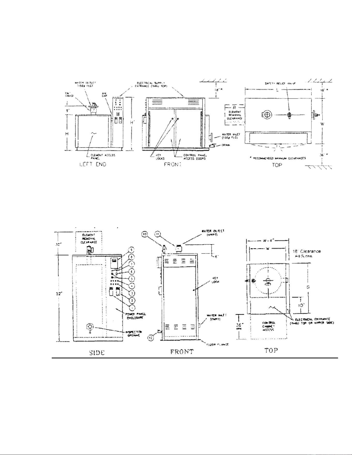
2.4.2 Leave a permanent space for element removal opposite element access panels as
shown on the Dimensional Drawing (DD), and 36 inches opposite electrical panels.
NOTE: Electric panels require 42” opposite any opposing conductive surface.
6
Figure 1 –
Minimum Clearance Recommendations and General Dimensional Data for
Boiler
LOCHINVAR Electric Hot Water (HW)
LOCHINVAR Compac (PCW)
NOTE: Consult Local codes for specific requirements and refer to the Dimensional Drawing
and Wiring Diagram provided with unit.
NOTE: Removal clearance required on both ends for HW_D and ST_D.

7
3.0 INSTALLATION
3.1 Piping Connections
NOTE: Some of the following piping may have been completed at the Factory.
3.1.1 Boiler piping connections and values MUST comply with state and local codes, in
addition to compliance with ANSI piping requirements.
CAUTION: The pipe extensions outside the unit are usually the extensions of pipes
which are permanently welded into the unit’s vessel. Normally the only removable
(threaded) connection is the drain pipe. DO NOT ATTEMPT TO REMOVE ANY OTHER
PIPING.
3.1.2 Install the safety relief valve(s) on the pipes provided. Plumb the relief valve
outlet connections full size to the floor drain. Check local codes for proper safety valve
discharge for steam boilers above 15 psi, which normally are required to be piped to
overhead discharge outside safely away from personnel.
3.1.3 Hot water boilers may be equipped with an air vent pipe on the top of the boiler.
Plumb this connection to the expansion tank or install an automatic air vent on this
pipe.
3.1.4 The direction of flow through hot water boilers and water heaters must be from
the inlet to the outlet (IE: bottom to top). Do not reverse these connections.
NOTE: Do not oversize feedwater piping and values on steam boilers, as this may result
in severe pressure fluctuations during feedwater cycles if the fill rate is too rapid.
3.2 Electrical Connections
3.2.1 Power Feed Wiring
The recommended wire size is listed on both the unit’s Bill of Material (BOM) andthe
Wiring Diagram (WD). Also, the full load amperage and maximum voltage are stamped
on the unit’s nameplate. The feeder must be sized for 125% of the full load amperage in
accordance with Article 424-3 of the NEC. The wiring must have insulation rated 75°C or
greater. Copper wiring is recommended for all power connections. The recommended
size is noted in the ‘Notes” on the wiring diagram.
CAUTION: Do not exceed the maximum voltage as listed on the nameplate. For
resistance loads, amperage increases proportionally with voltage.
3.2.2 Equipment Grounding Conductors
The unit is equipped with grounding lug(s) inside the power panel(s). The grounding
conductors must be installed and sized in accordance with NEC Article 424-14. The
recommended size is noted in the ‘Notes” on the diagram.

8
3.2.3 Control Wiring
Alteration of, or additions to, control wiring may void both the Underwriters
Laboratories Listing and the Manufacturer’s Limited Warranty. Field-installed controls,
control connections, and modifications must be approved in writing by the Factory.
NOTE: All power connections are 3-Phase, 3-Wire. (Exception: If unit is single phase.)
There is no provision for a neutral connection; (IE: the unit should not be wired ‘wye’ or
‘star’).
3.3 Filling the System
3.3.1 The system and the boiler / water heater must be thoroughly flushed before the
final fill. Steam boilers should be ‘boiled out’ before operation.
3.3.2 Water Treatment
Consult a local water treatment firm for recommendations on proper water treatment
and boilout procedure to prevent damage to the boiler vessel, components and heating
elements. The internal materials of boilers are Steel, Incoloy and Cast Iron, which all are
compatible with standard boilout compounds. In lieu of a commercial boilout
compound, the following mix of chemicals can be used for every 1,000 gallons of water:
30 lbs. TSP (tri-sodium phosphate; Na
3
PO
4
), commonly found in many building supply
centers.
5 lbs. caustic soda (50% pure sodium hydroxide; NaOH)
2 lbs. ordinary powdered laundry detergent. (Example: Tide)
These chemicals should be dissolved in warm water prior to their addition to the boiler.
The boiler should be heated for at least 3 hours, then drained and flushed.
NOTE: Standard hot water boilers are suitable for ethylene glycol mixtures up to a
50/50 mix.
4.0 PRE-STARTUP INSPECTION
4.1 Minimum Equipment Required For Startup And
Troubleshooting
Volt-Ohn Meter
Clamp-On Ammeter
Megohm Meter
Torque Wrench – inch lbs
Torque Wrench – foot lbs
4.2 Mechanical System Checks
4.2.1 Plumbing Connections Completed
Inlet / Makeup water?
Discharge / Outlet?

9
Drain / Blowdown?
Relief / Safety Valve discharge?
4.2.2 Feedpumps / Circulating Pumps
Pumps wired, connected and checked for proper rotation?
Is the boiler filled to the proper level with water?
4.2.3 System Flush
Has the System been flushed?
Has the unit been cleaned of all construction debris?
4.2.4 Valves
Are all valves in the proper open or closed positions?
4.3 Electrical System Checks
WARNING:
All POWER supplying boiler should be off and locked out! with the unit(s) main power
switch(es) OFF and locked out.
□ Inspect all components, external and internal, to assure that there has been no
damage during shipment or installation.
□ Remove one of the unit’s control circuit transformer primary fuses. Then check the
resistance phase-to-phase for all three phases. Make sure that there are no short
circuits phase-to-phase or phase-to-ground.
With a megger (500VDC minimum) check contactor load side terminals to ground. If a
reading of <1 megohm is obtained, consult the Factory.
□ Remove element access panel(s) and open doors to the electrical control panel(s).
Run an inspection of the tightness of all electrical connections (IE: at fuse lugs, power
entrance lugs, contactors, heating elements).
All branch circuit connections should be tightened to 40 – 50 inch lbs. (actual value
listed on components). Torque to avoid component damage from heat build-up.
This tightness inspection is vital, because the vibration during shipment can often loosen
electrical connections. If this is not done, damage may occur to component parts when
power is switched on, and those damaged parts will not be covered under the
manufacturer’s Limited Warranty.
NOTE: See Maintenance Section on rechecking the torque on these components after
an initial break-in period. Typically one to two weeks after start-up and then at least
annually.
□ With an ohmmeter, check the resistance between the phases on the load side of the
contactors. Each should read the same and approximately what is shown on the wiring
diagram.
□ Check the electrical panels for loose material, dust and / or moisture. Thoroughly
vacuum the panels if dust or foreign materials have accumulated there.

10
If there has been severe exposure to dust, the contactors should be disassembled and
cleaned. Dust in the contactors will cause contractor chattering and eventual
destruction of the contacts.
All components should be clean and free of dust, moisture, and foreign matter!
□ Verify that field-installed control and load connections have been properly
completed.
□ Check the tightness of all control circuit connections.
4.4 Heating Element
CAUTION: Moisture in the elements may result in damage to the elements.
NOTE: There is a possibility that during shipment or storage prior to operation, the
elements may accumulate moisture. The moisture will turn to steam when the
elements are turned on and may rupture the element casing.
4.4.1 How to Check Elements for Moisture
Take a reading with a megger between the contactor terminals (load side) to ground for
each contactor. Moisture is present if the reading is less than 1 megohm for standard 3-
phase connection.
4.4.2 Removal of Moisture in Element (method #1)
Remove the fuses going to that contactor. The fuses should be removed so that, during
the first day of operation, the affected element will not be energized allowing the hot
water to drive the moisture out at a controlled rate.
4.4.3 Removal of Moisture in Element (method #2)
An alternate heating method is to direct a heat lamp at the suspect element, or remove
the element, bake it in a 200°F oven for 8 hours, then reinstall and rewire.
4.4.4 After completion of either of the above methods for moisture removal, re-check
the element with a megger. When the reading indicates an acceptable level, the
element may be put in operation by replacing the fuses.
4.4.5 Replace all Element Access Panel(s) and close electrical / control panel doors.
4.5 Inspection Power / Voltage
4.5.1 Verify the boiler ON / OFF control switch is in the ‘OFF’ position. Close the boiler
main power switch, turn the control switch to ‘ON’ and then:
4.5.1.1 Check the phase-to-phase voltage at the main terminals in the boiler electrical
panel. The phase-to-phase voltage between any two of the phases must not exceed the
boiler nameplate voltage.
4.5.1.2 Check the voltage at the boiler control circuit fuse. It should be between 105
volts and 125 volts.
4.5.1.3 Open the boiler main power switch.
4.5.2 If all of the above prove satisfactory, proceed with ‘Startup Instructions’ (Section
5.0). Replace all covers and close all doors.

11
5.0 STARTUP INSTRUCTIONS
5.1 Control Settings
5.1.1 Controller
(See Parts List for Part No. and Type)
5.1.1.1 The controller is the pressure or temperature sensing device which controls the
operation of the contactors directly or indirectly via the step control.
5.1.1.2 Set the Controller for the desired Outlet Water Temperature (or Steam
Pressure).
NOTE: (For Water Heaters) The maximum water temperature for lined vessels is 160°F,
except for cement lined vessels which can operate at 180° F.
NOTE: (For Hot Water Boiler) Outdoor reset (dual bulb) controllers are set at the
temperature at which the Boiler should operate when the outdoor temperature is 70°F
(this outdoor reference temperature is adjustable on most solid state controls; fixed on
Honeywell T991B controllers). The reset ration (fixed on Honeywell T775J) is the
number of degrees the boiler control temperature will increase for a 1 degree decrease
in outdoor temperature.
5.1.1.3 Throttling Range
The throttling range is the number of degrees (or psi) the outlet water temperature (or
steam pressure) must change to drive the step controller from full-off to full-on.
For instance, if the controller is set at 160°F, and the throttling range is set for 10°F, the
step controller will be full-on at 165°F (1/2 of throttling range above setpoint). The
more stable the load on the unit (from system demands), the smaller the throttling
range may be set.
5.1.2 High Limit (Temperature or Pressure)
Set the automatic reset high limit 10°F ( or 5 psi), or twice the throttling range,
whichever is greater, above the setting of the controller.
Manual reset limits should be set slightly higher than the automatic reset limits. For
steam boilers, the manual reset high limit should be set at lease 10% below the safety
valve set pressure.
5.1.3 Low Water Cutoffs
These cutoffs are always factory-set. If additional cutoffs are field-installed, the cut-offs
should be at least three inches above the highest heating element. Manual reset cutoffs
should be set below automatic rest cutoffs.
5.1.4 Low Limit Sensors (Temperature or Pressure)
Low limits should be set below the controller setting by at least the same margin as
specified for high limits to be above the controller setting.
5.2 Operating Instructions
5.2.1 With the unit’s control power ON/OFF or ON/OFF/PREHEAT switch ‘OFF’, close
the main power switch(es).
NOTE: Units with shunt trip disconnects and remote 120-volt control power may
require turning the control power switch ‘ON’ and activating the 120-volt control power,
before closing the main power switch(es).

12
5.2.2 Electric Door Interlocks
For units equipped with electric door interlocks, do not attempt to open electrical panel
doors after the main switch is closed. The lock tabs are mechanically restrained by the
electric interlocks.
5.2.3 Switch all the ‘enable / disable’ pilot switches the ‘OFF’ position (toggle down).
5.2.4 120-Volt Power Source
If a separate 120-volt power source is provided, close it’s disconnect switch.
5.2.5 Turn the control power ON/OFF or ON/OFF/PREHEAT switch to ‘ON’.
5.2.6 Alarm and Reset Circuits
5.2.6.1 If the alarm sounds when the control switch is turned ‘ON’, depress the alarm
silence button. Check the unit to make certain that no limit condition exists by noting if
the alarm pilot is illuminated. The alarm will sound momentarily on some units when
power is initially applied
5.2.6.2 Units with Manual Rest Button(s) may require resetting of the manual reset
switch upon initial application of power, and after the interruption or power or the trip-
out of a limit control.
5.2.7 Sequencing of Elements Circuits
5.2.7.1 On units with step controls, the unit will always start with no steps energized.
5.2.7.2 As the steps begin cycling on, the LED’s on the step control (circuit board inside
cabinet) will light up one at a time, indicating that step control is operating properly.
NOTE: The enable pilot lights or contractors will not be activated at this time since the
‘enable / disable’ switches are in the off position).
5.2.7.3 With the step control board full on, individually enable each step. The
respective pilot light should light and the contactor(s) applying power to the respective
elements.
5.2.7.4 For units with ON/OFF/PREHEAT switches, only part (approximately 25% may
be activated when the switch is down in the ‘PREHEAT’ position. This PREHEAT option is
now rarely used.
5.2.7.5 If PREHEAT switch is used When the outlet water temperature (or steam
pressure) is at or near setpoint turn the ON/OFF/PREHEAT switch OFF’, then to ‘ON’
again. The controls will recycle to the no-load condition. The steps should then begin
to cycle on as needed, and all of the steps may come on if necessary.
6.0 SEQUENCE OF OPERATION
6.1 Activation of Heating Element Circuits
6.1.1 Contactors
The heating elements are energized by pilot operation. That is, the power to an
element circuit is supplied through the contacts of a contactor. The contactor is
activated (on a call for heat) by the closure of a temperature (or pressure) switch or by a
contact in the step control circuit.

13
6.1.2 Fuses
All power leads to the elements are fused. The fusing is on the line side of the
contactors.
6.2 Sequencing Controls
6.2.1 Staged Control Circuit
6.2.1.1 In this type circuit, the contractor coils are energized directly by the contracts
of immersion thermostats (or pressuretrols). There is usually on thermostat (or
pressuretrols) for each stage; or a multi-stage thermostat (or pressuretrols) may be
provided in some cases.
6.2.1.2 The safety limit devices (high temperature, low water, etc.) interrupt the power
to the contactor coil circuits.
6.2.2 Proportional Step Controls
6.2.2.1 Step Control Sequence
The controller senses the unit’s water temperature (either via 135-ohm device or
thermistor) or steam pressure (either via 135-ohm device or 4-20 ma transducer). The
output signal or the controller causes the step control to sequence the steps on, or off,
depending on whether the unit’s output is below or above setpoint.
When one of the switches closed on the step control, a contractor coil (or coils) is
energized in a step-wise fashion. This type of step control will mid-position(bring on
half of the steps) when the unit’s water temperature (or steam pressure) is at setpoint.
EXAMPLE: An 8 step steam boiler with the pressure controller set at 12 PSIG, will have 4
steps on when the boiler steam pressure is at 12PSIG.
6.2.2.2 Progressive Sequence Step
Controls
These controls are provided as standard and include Selectronix SLC series and Viconics’
model R851B. They provide first-on, first-off staging of the element circuits.
As the unit’s temperature (or pressure) drops below setpoint, the control brings on
more steps. As the temperature (or pressure) increases and approaches setpoint, the
step control drops out stages. The first step to drop off is the one that has been on the
longest. This provides even usage of the system’s components.
6.2.2.3 Linear Sequence Step Controls
This type of step control is limited to the some Selectronix models and Viconics’ model
R851B. In this sequence progression, the control applies power by progressing from
Step 1 to the maximum number required to satisfy the load, and then decreases power
by retracing this sequence down toward the first step.
NOTE: Refer to the applicable vendor literature provided on the step control installed in
your unit.
6.2.3 Recycle Feature
All step controls now incorporate the recycle feature which returns the step control to
the no-load condition upon loss of control power.

14
6.2.4 Manual Step ‘ENABLE / DISABLE’ Toggle Switches
All units with >1 step now include manual ‘ENABLE / DISABLE’ toggle switches to provide
a positive ‘OFF’ override of each step. These are used to disable a faulty step, limit total
output or allow for a slow preheat.
6.2.5 Preheat Switch (Boilers Only)
The preheat switch is a manual limit switch. In order to preheat the boiler, the
ON/OFF/PREHEAT switch must be in the down position. When the ON/OFF/PREHEAT
switch is in it’s down or PREHEAT position, the boiler output is limited to approximately
25% of full load power. This allows the operator to limit the boiler output during startup
cycles (particularly if the boiler is shut off at night and turned on again in the morning),
which could lessen electrical demand charges.
When the boiler has been brought up to the setpoint temperature (or pressure), the
ON/OFF/PREHEAT switch is moved slowly from it’s down or PREHEAT position to it’s up
or ON position passing through the OFF position to cause the step control to recycle to
the NO LOAD position. Thereafter, the boiler can operate up to full load if necessary.
NOTE: The PREHEAT switch is included as an option on boilers of 9 or more steps. It is
intended to be used to prevent setting demand peaks on ‘cold starts’. It does not have
to be used if so desired.
7.0 OPERATIONAL TESTING
7.1 Standard Controls
7.1.1 135-ohm Controllers
(T991, T915, L91,etc.)
With the water temperature (or steam pressure) at setpoint, the step controller should
bring on nominally one half of the steps. An adjustable proportional band is provided
on the controller (sensor) to enable tuning the unit to system demand.
7.1.2 Solid State Controls
With the water temperature (or pressure) at setpoint, the step controller should bring
on nominally on half of the steps. Adjustable
time delays between steps and adjustable proportional bands are normally provided on
the step control to enable tuning the unit to system demand. Most solid state controls
also include band width adjustment at the control itself, and normally include PID
control action.
IMPORTANT: The timing between stages adjustable (with step control). Steam boilers
normally have delay of between 15-20 seconds while stepping up and 3-5 seconds while
stepping down. Water boilers can normally respond slower so 25 – 40 seconds up and
5– 10 seconds down is usually appropriate. The slower the step sequencing, the less
wear on both the contractors and heating elements (yet still able to control the process
as needed) the less heat is generated in the cabinet which results in longer component
life.

15
7.2 Outdoor Reset Controls
7.2.1 135-ohm Type Outdoor Reset Controller (Hot Water Boilers Only) (Honeywell
T991B type)
These controllers have a fixed reset ratio: either 1-to-1, 1-to-1.5 or 1.5-to-1. The
outdoor reference temperature is 70°F (IE: the boiler outlet water control point
temperature is equal to the setting on the controller when the outdoor temperature, at
the outdoor bulb, is 70°F). In order to test the operation of this controller:
7.2.1.1 Check the outdoor temperature at the outdoor air sensing bulb; then
determine the number of degrees this temperature is above, or below 70°F.
7.2.1.2 Check the boiler outlet water temperature; if the outdoor temperature is below
70°, multiply the difference between 70°F and the actual outdoor temperature by the
reset ratio (1.0, .67 or 1.5); and subtract this from the temperature of the boiler outlet
water.
7.2.1.3 Then set the controller at this resultant temperature; the step controller should
maintain nominally half of the steps on. Setting the OUTDOOR RESET CONTROLLERS
basic information is shown in Table 1 below.
Table 1
SETTING THE TEMPERATURE CONTROLLER
Reset Ratio:
1:1-1/2 (IE: 2/3:1)
Outdoor Temperature:
40°F
Boiler Water Temperature:
130°F
Step ‘A’
Difference between outdoor temp and 70°F
70 – 40 = 30°
Step ‘B’
Multiply 30°F times the Reset Ratio 2/3 (and then)
30 x 2/3 = 20°F
Subtract 20°F from the Boiler Water Temp 130°F
130 – 20 = 110°F
Step ‘C’
Set the Controller at 110°F
Note:
If the Outdoor Temperature is above 70°F, add the difference in Step ‘A’,
multiplied by the Reset Ratio, to the Boiler Water Temperature.
See Honeywell manual for specific details.
7.2.2 Solid State Dual Input Reset Controls
(Honeywell T775J controls)
These are dual sensor reset controllers with adjustable reset ration and outdoor
reference temperature. The ‘reset ratio’ is the ratio of the change in the temperature at
the secondary sensor to the opposing change in the control point. If the reset ratio is
2:1, every 2°F change at the outdoor sensor will cause an automatic inverse change of
1°F at the control point.
EXAMPLE: Assume a reset ratio of 2:1, a primary set point of 100°F, and a secondary
setpoint at 70°F. The first number of the reset ratio indicates change in outdoor
temperature; the second, the change in the control point. If the outdoor temperature

16
drops from 70°F to 20°F, a change of 50°F, the control point will increase from 100°F to
125°F, a change of 25°F.
NOTE: Refer to the applicable vendor literature provided on both the setpoint controls
and step controls installed in your boiler.
8.0 PREVENTATIVE MAINTENANCE
8.1 General
Electrical immersion heating element boilers and water heaters are automatic, quiet
and safe. Consequently, they are all too often neglected. Like any piece of electrical /
mechanical equipment, they require care and maintenance to keep them in top working
condition.
If electrical connections are allowed to become loose or dirty, there is danger of an
electrical fault. If the elements are not inspected periodically for leaks, the water from
leaking elements can leak onto adjacent elements, causing external element damage
and resulting in blowing of load fuses in the boiler electrical panels. If the boiler water is
not properly treated, element failure could occur due to the formation of scale.
Treat the boiler with respect.
CAUTION: Always work on the boiler with all electrical power sources disconnected.
8.2 Water Treatment (Boilers Only)
Boiler water should be periodically checked through a sampling procedure. Properties
should be maintained in accordance with Table 2 at the end of this section. For
consultation relative to water treatment, please contact a reputable water treatment
firm.
8.3 Electrical System Maintenance
8.3.1 Clean the control cabinets periodically (as often as needed) to keep both the
interior and the exterior free of dust, moisture and foreign matter. The interior cleaning
of the electrical panels must be done with the POWER OFF!
NOTE: For units supplied with control cabinet cooling fans, the condition of the fan
filter must be periodically checked and the filters cleaned or replaced as necessary.
8.3.2 With the POWER OFF, periodically check the tightness of electrical connections;
particularly at power entrance lugs, fuses (line side) and contractors (load side). This
should be done at time of commissioning, at 7 – 14 days thereafter and at least
annually. Replace any components that show signs of heat damage (IE: discoloration,
charring, melted insulation, etc.).

17
8.3.3 Inspect the condition of the contactors. Look for burned or corroded contacts or
overheated coils and wires. If the contactors chatter or hum during operation, they
should be either disassembled and cleaned to remove dust or other foreign material in
the mechanism or replaced.
8.3.4 Inspect the heating elements. Make sure that the terminal contacts are tight,
clean, and corrosion-free.
8.3.5 Check all the wiring throughout the unit for frayed or brittle insulation. Replace
any wiring showing insulation degradation.
8.4 Boiler Mechanical System Maintenance
8.4.1 With the POWER OFF, remove the element access covers. Inspect all internal
vessel connections, particularly at the heating elements. Spot check torque on element
flange bolts. The acceptable torque range is 10 – 15 ft. lbs.
CAUTION: Do not over tighten elements!
8.4.2 Remove and replace any leaking elements or element gaskets. Inspect handhole
and manhole gaskets. If these gaskets are brittle, they should be replaced.
WARNING: Over-torquing of the elements nuts will damage the element gasket!
8.4.3 Repair any leak at any place on the unit or adjacent piping. Re-torque flange
bolts on system piping.
8.4.4 For all boilers, the interior of the pressure vessel must be inspected at least once
a year. If there is any presence of scale, refer to ‘Preventative Maintenance Water
Treatment’ above a consult a local water treatment firm immediately. Scale formation
on the elements will cause heating element failures. Scale formation elsewhere in the
boiler can cause erratic control operation / failure, particularly on water level controls.
8.4.5 When the boiler is inspected, rod out the pipes to the water column(s) and
inspect the operation of the float(s) in the level controller(s).
8.4.6 Remove and clean the low water cutoff probe.
8.4.7 Steam Boiler Special Maintenance
8.4.7.1 All LOCHINVARsteam boilers are supplied with a surface blow-off connection. If
surface blowoff valves are not Factory-installed, they should be installed in the field.
The surface blow-off should be used as often as necessary to remove organics which
accumulate at the water surface, and to limit TDS. (Boiler water TDS – total dissolved
solids should not exceed 3500 ppm).
8.4.7.2 Both the boiler and water column should be blown down periodically to
remove bottom sludge.

18
8.4.7.3 The water column should be blown down daily to assure proper operation of
the level control / LWCO assembly.
8.4.7.4 Water Treatment
Water treatment is required for satisfactory operation of steam boilers to prevent both
deposition of scale and corrosion from acids, oxygen and other harmful elements that
may be in the water supply. A qualified water treatment specialist should be consulted
to establish a proper water treatment program.
8.5 Element Replacement Procedure (4-Bolt Style Element)
CAUTION: Before element replacement, make certain main power to the unit is turned
off, that there is no pressure in the unit, and that the unit is drained below the element
opening.
NOTE: To prevent hazardous conditions of leaking water / steam at the element
terminal ends, defective elements or element gaskets should be replaced immediately
upon leak detection.
8.5.1 Adequately tag wire and then remove wires from defective elements.
8.5.2 Remove element by removing the four (4) attachment nuts.
8.5.3 Install replacement element with the new gasket and torque nuts to 10 -15 ft. lbs.
WARNING: Do not exceed 15 ft. lbs!
8.5.4 Connect phase wires to new element.
8.5.5 When the unit is filled and pressurized, check for leaks.
Table 2
Recommended Feedwater and Boiler Water Properties
FEEDWATER
Type
of
Boiler
Hardness
(ppm)
pH
Oxygen
(cc/l)
TDS
(ppm)
Total Dissolved
Solids
Hot Water
0 – 10
7.5 – 9.5
4.0
0 – 500
Steam
0 – 5
7.5 – 9
.03
0 – 350
BOILER WATER
Type
of
Boiler
Hardness
(ppm)
pH
Oxygen
(cc/l)
TDS
(ppm)
Total Dissolved
Solids

19
Hot Water
0 – 10
7.5 – 9.5#
0
0 – 5000
Steam
0
7.5 – 9.5#
0
0 – 3500
# - The limit of 9.5 pertains to copper elements; a pH of 10.5 is allowable for incoloy elements.
8.6 Typical Preventative Maintenance List
NOTE: This list may not be all inclusive! Read and understand entire ‘Operation and
Maintenance Manual’ and take into consideration any modifications and / or optional
equipment for this unit:
WARNING: MAIN POWER MUST BE TURNED OFF TO DO ELECTRICAL CHECKS!
Daily
Bottom Blow-down to keep sludge from building up and help
with water TDS
Surface Blow-off to remove floating solids and maintain
proper TDS
Ensure valves, connections, piping, gaskets, etc. are not
leaking
Weekly
Verify that boiler water properties are within desired
parameters
Blow-down water column and (sight-glass) to prevent sludge
from building up in piping.
7 – 14 days
After
STARTUP
(Fax form)
Re-torque screws on distribution, fuse blocks and contactors
to their specified torque (typically 45 – 50 in – lbs.)
Re-torque any bolts on copper distribution from disconnects
or circuit breakers to typical torque valves for the size of bolt
used.
Monthly
to
every
Six Months
Check for any heating element gasket or manway gasket
leaks
Clean filters on cooling fans to maintain proper air flow
Check fuses and heating elements with an ohm meter for
proper values.
Look for signs of overheating on fuses, fuse blocks,
contractors and wires. Any discolored, charred or melted
components should be replaced. Ensure all screws are
torqued to their proper values for any replaced components.

20
Annually
Inspect interior of tank for sludge or scale. Clean tank and
modify water treatment chemistry as necessary.
Replace brittle element gaskets, valve gaskets and manway
gaskets as necessary.
Re-torque ALL distribution, fuse block and contactor
screws to the proper value.
Re-torque any bolts on copper distribution from disconnects
or circuit breakers to typical torque values for the size of bolt
used.