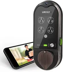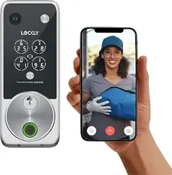
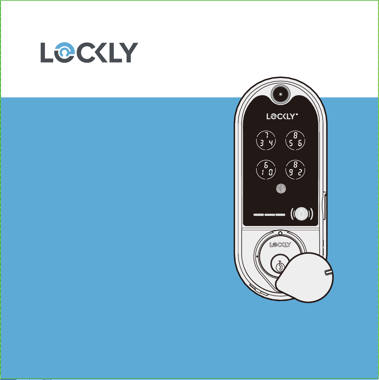
VISION
™
DEADBOLT EDITION
INSTALLATION
GUIDE
Go to Lockly.com/installation to watch a video
version of this installation guide.

Reference installation parts overview foldout on back page
Welcome!
This guide will walk you through step-by-step how to
install and get your Lockly Vision
™
up and running.
Installation generally takes less than 30 minutes. If
you have any questions please reference our online
support at: Lockly.com/support or call (669) 500-8835
for help.

CAUTION: lock contains electrostatic-sensitive (ESD) parts. Best practices: ground yourself by
t
ouching a metal surface other than lock to discharge any ESD you might have; don't wear
clothes prone to static (ESD); avoid touching electronic internal pins and circuit board.
Prepare door: remove existing deadbolt or use provided template to bore new holes.
3
Phillips Screwdriver
To complete the installation you will need:
Flathead Screwdriver
Tape measure or ruler
1-⅜" (35mm)
to 2" (50mm)
1" (25mm)
2-⅜" (60mm)
or
2-¾" (70mm)
Cross-bore
2-⅛" (54mm)
Preparation
4
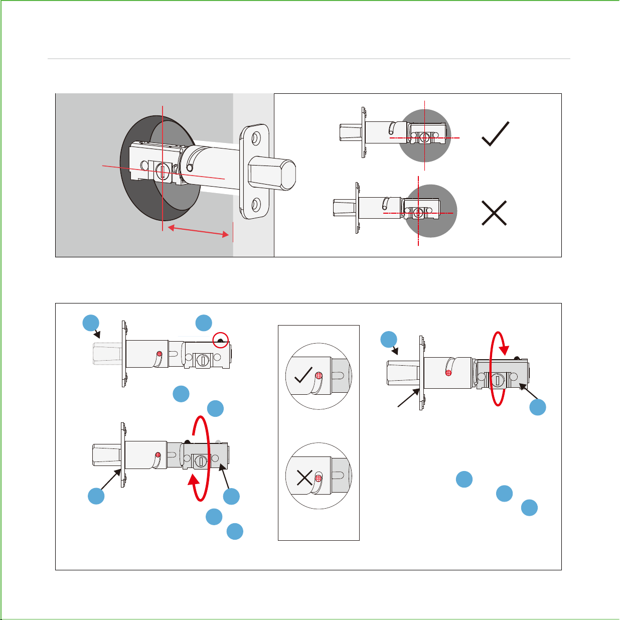
Deadbolt slot must align to the center of the door hole. Adjust as shown if needed.
The deadbolt comes set to 2-3/4" (70mm). Adjust length to 2-3/8” (60mm) if necessary.
(wear gloves to protect from possible pinching).
Hold the metal plate and
twist the deadbolt body
clockwise till it snaps to 2-3/8"
Deadbolt comes set at 2-3/4"
(70mm). To return to default,
while deadbolt is extended,
hold the metal plate and
twist the deadbolt body
counter-clockwise till it snaps to
2-3/4"
Push the crank to
extend the deadbolt
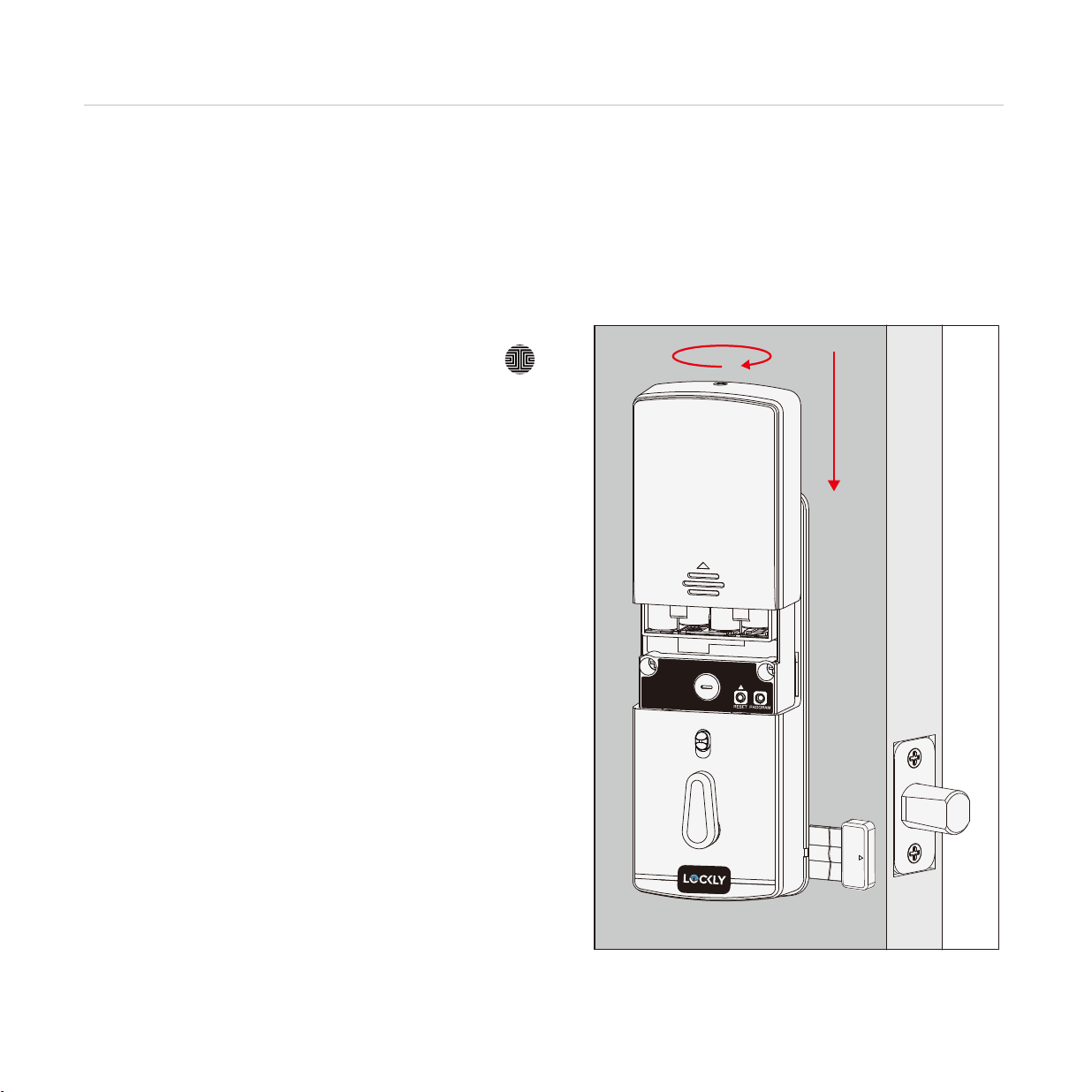
ADJUST DEADBOLT AND INSTALL
Step 1
B
B
B
B
A
C
C
C
D
D
D
D
A
2-3/4" (70mm)
or 2-3/8” (60mm)

5
Extend the deadbolt by inserting a flat-head
screwdriver into the slot and turning clockwise.
Insert the deadbolt into door edge, make
sure that the right side is up and the slot
is i
n the vertical position. Secure with 2
screws.
(2X)
K
K
ADJUST DEADBOLT AND INSTALL
Step 1continued
1
2

INSTALLING EXTERIOR ASSEMBLY (B)
6
Check the exterior assembly (B) alignment
to door hole and deadbolt before peeling
off film on adhesive strips.
Peel film from adhesive strips and make sure torque blade is in the vertical position with the
deadbolt extended. Place assembly and torque blade through the deadbolt slot and
guide connection cables through the cross-bore hole under the deadbolt as shown. Complete
mounting by aligning and securing until flush to exterior door surface.
Step 2
Vertical
Extended
EXTERIOR VIEW
Under

INSTALLING INTERIOR ASSEMBLY (G)
7
1: Check interior mounting plate
alignment to your door hole before
securing with adhesive strips.
3:
Insert and tighten by hand 2 screws
located on the left and right of the
blade. Check alignment and tighten
with screwdriver until mounting plate is
securely placed on door.
TIP: when installing screws by hand, turn screws clockwise several turns then
counterclockwise one turn to ensure smooth threading and no cross threading.
4: Use the key to ensure deadbolt locks and
unlocks smoothly (no binding or rubbing).
IMPORTANT: when finished, leave the dead-
bolt extended and remove the key before
proceeding to the next step.
2: Align and secure mounting plate with
adhesive strips. Guide connection cables
through the hole and secure to the lower
left notched hole.
2X
F
F
D
Step 3
Remove key when finished
Leave deadbolt extended

8
Lockly Vision
™
comes with a pre-wired door sensors consisting of two parts:
Part (P) - Wired Sensor
Part (Q) - Sensor Magnet
About door sensors
Door sensors provide real-time door condition status, such as the ability to verify if the
door is securely closed. It also sends push notifications to your phone whenever your
door opens and enables voice control with Amazon Alexa or Hey Google.
Removal of Sensor (optional)
There may be circumstances where the sensor cannot be installed because of
molding/door limitations or is not aesthetically desirable. The sensor wired to the lock is
removable by carefully pulling its connector from the circuit board. If removed, some
features and functionality will not be available, such as real-time condition status.
TIP:
Lockly door sensors comes in Grey (PGA715) and Matte Black (PGA716) that
can be ordered through our customer hotline: (669) 500-8835 or by email:
IMPORTANT: Gap must be less than 3/4” when installed.
When installed on door, the distance between the wired sensor and
sensor magnet must be less than 3/4” in order for the sensor to work.
If door frame is higher than door, add included foam pads to level
parts (P) and (Q) with each other as much as possible.
PREPARING DOOR SENSORS FOR INSTALLATION
Step 4
Do not mount (install) door sensors yet. You will install in step 7.

Right
or
Left
When installing the door sensors, make sure the
arrow on the wired sensor (P) aligns to the arrow of
the sensor magnet (Q) as close as possible.
The sensors need to be as close
to level as possible. If needed,
use the adhesive foam pad(s) to
adjust the height of the wired
sensor.
Sensors can be positioned on either left
or right side (see page 10).
2-3/4" (70mm)
2-3/8" (60mm)
3/4" (20mm)
Foam pad
(P) (Q)
9
PREPARING DOOR SENSORS FOR INSTALLATION
Step 4
continued
The interior assembly comes with the pre-in-
stalled wired door sensor setup for a right
swing doors with 2 ¾" (70mm) backset*.
Trim excess part (P) for doors with 2 ⅜"
(60mm) backset as shown below.
For left swing doors, re-route the door
sensor wire through the side channel.
Pull the foam pad then re-insert to
secure the wire. Discard the excess
part (e) for doors with 2 ⅜" (60mm)
backset as shown below:
*Backset = distance of the door edge to the center of the cross-bore door hole.
DO NOT INSTALL THE SENSORS YET
Pull foam pad Insert form pad
PREPARING DOOR SENSORS FOR INSTALLATION
3
2
1
(P)
10
Step 4
continued
Trim excess here for
2 ⅜" (60mm) backset*

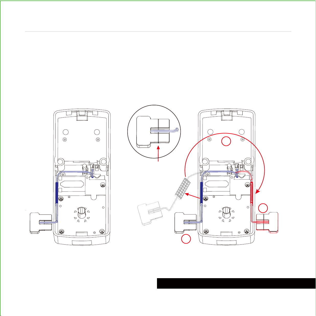
Plug the larger cable coming through mounting plate (D) into the interior assembly (G) as
shown. Tuck cable under eyelet hooks and route to the right on interior assembly (G).
INSTALLING THE INTERIOR ASSEMBLY (G)
11
Step 5
Connect to screw tightly by
hand as shown. Plug into ,
match red side of plug with red on
socket - insert tightly.
Do not touch pins inside*
Call our Customer Care Hotline
(669)
500-8835, for help if the
pins are not
centered or bent.
A
A
B
B
X
Y
YX
A
B

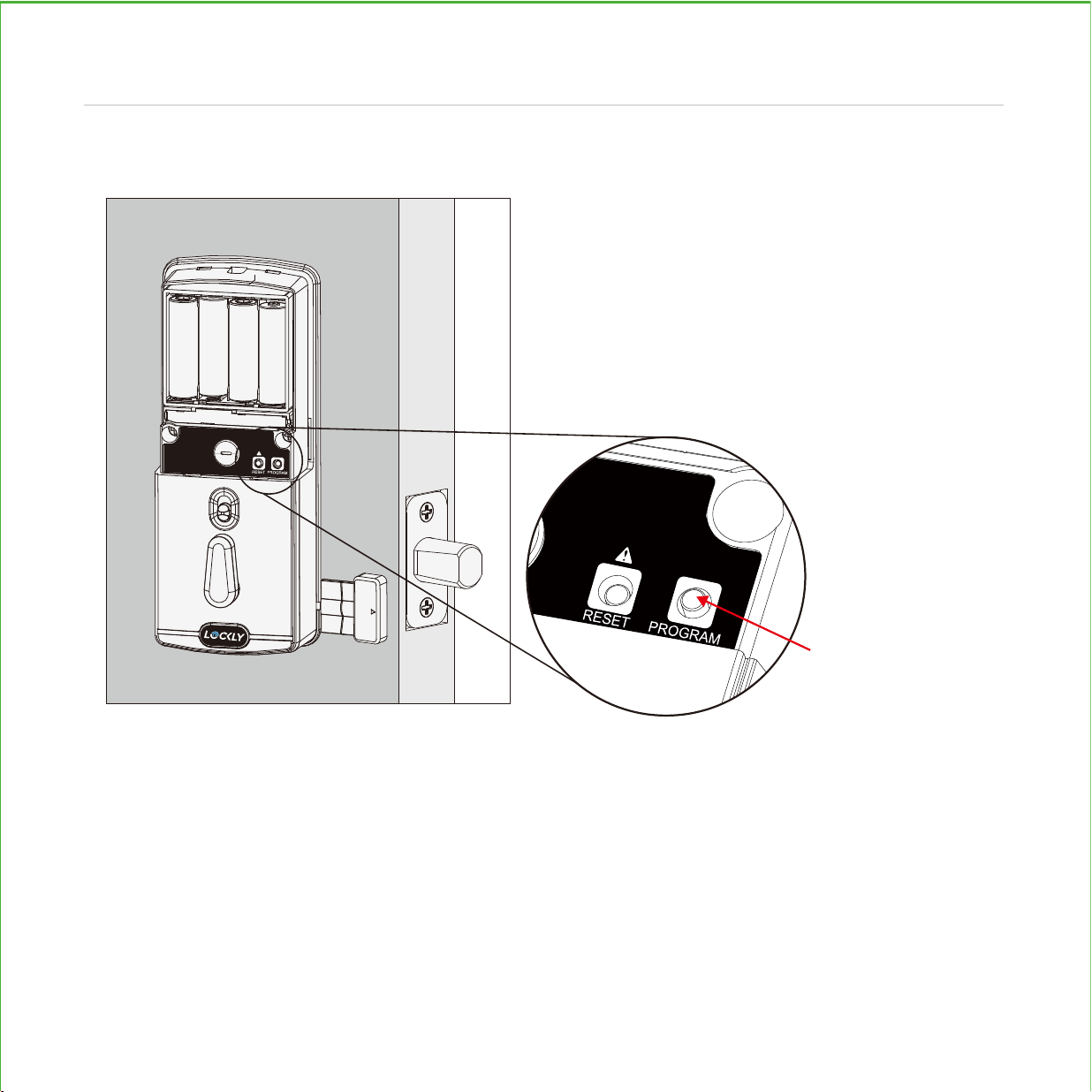
RESET
PROGRAM
Before placing the interior
assembly onto the mounting
plate, ensure the thumb turn
is vertical.
Place the interior assembly
against the mounting plate
and make sure the torque
blade is inserted to the thumb
turn shaft.
Secure the interior assembly
to mount plate door with
2 screws.
Torque Blade Thumb turn shaft
RESET
PROGRAM
H
2X
H
INSTALLING THE INTERIOR ASSEMBLY (G)
12
Step 5
continued
RESET
PROGRAM
Align torque blade with thumb
turn shaft, make sure both are in
the vertical position.
13
INSTALLING BATTERIES
Step 6
1: With door open and deadbolt fully extended, place ribbon inside compartment and insert
8 batteries (note correct -/+ polarity).
2:
After all batteries are installed, PRESS and HOLD the program button for 10S. The lock will
automatically start self-check (release program button once check starts). The self-check
process determines right or left swinging door and is very important to ensure correct installation.
IMPORTANT: if lock is not properly installed it will open and close repeatedly (refer to next page #3).
PRESS & HOLD
for 10 seconds
14
INSTALLING BATTERIES
Step 6
3:
Once self-check completes ensure the lock operates smoothly by manually locking and
unlocking the door using the thumb turn on the interior assembly. The deadbolt should operate
smoothly without any interference or binding. If necessary, repeat step 2 and ensure that (a) the
deadbolt was extended and (b) the torque blade was inserted vertically while the deadbolt was
extended.
4: Swipe your hand across touchscreen. The lock should
close (lock). If the touchscreen is ON, touch , the
lock should lock as well. If deadbolt bounces back or
unlocks automatically it means something is not
installed correctly. Go back and repeat step 2, same
as above.
5.
Once self-check is complete, install battery cover (I)
and secure with screw on top (do not over tighten).

LOCK SENSOR (P)
Install on the interior side only. If necessary, trim tab from sensor (P) for doors with 2-3/8"
(60mm) backset. Clean surface of door and doorframe, remove film from adhesive, attach
and secure close to door edge as shown.
2-3/4" (
70mm)
2-3/8" (
60mm)
(P)
15
INSTALLING THE DOORS SENSOR
Step 7
Make sure you have prepared the door sensors for installation, see step 4
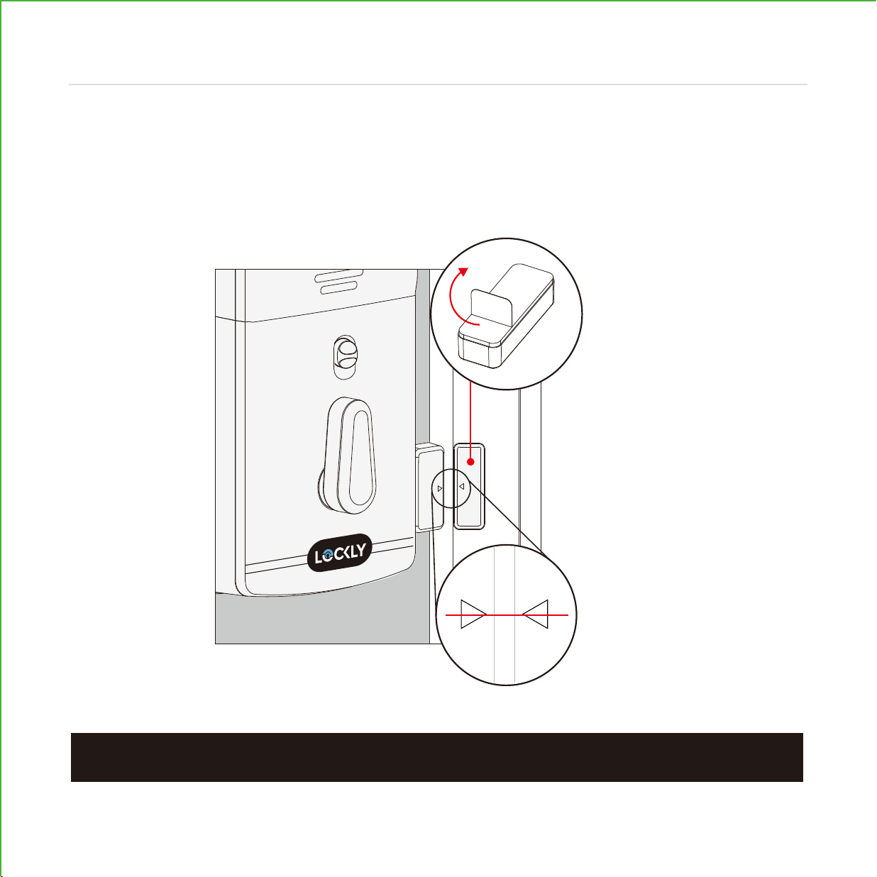
NOTE:
When properly installed, the Lockly logo blinks red when door opens and closes.
DOOR FRAME SENSOR (Q)
Manually retract deadbolt and close door. Dry fit sensor (Q) to door frame and check
for alignment. If needed, raise the height of the sensor to be more level with sensor (P)
by adding 1 or 2 of the included adhesive foam pads. Once satisfied both sensors are
as level as possible, remove film from adhesive and install with arrows aligned to each
other with less than a 3/4" gap between each sensor.
16
INSTALLING THE DOORS SENSOR
Step 7
(Q)
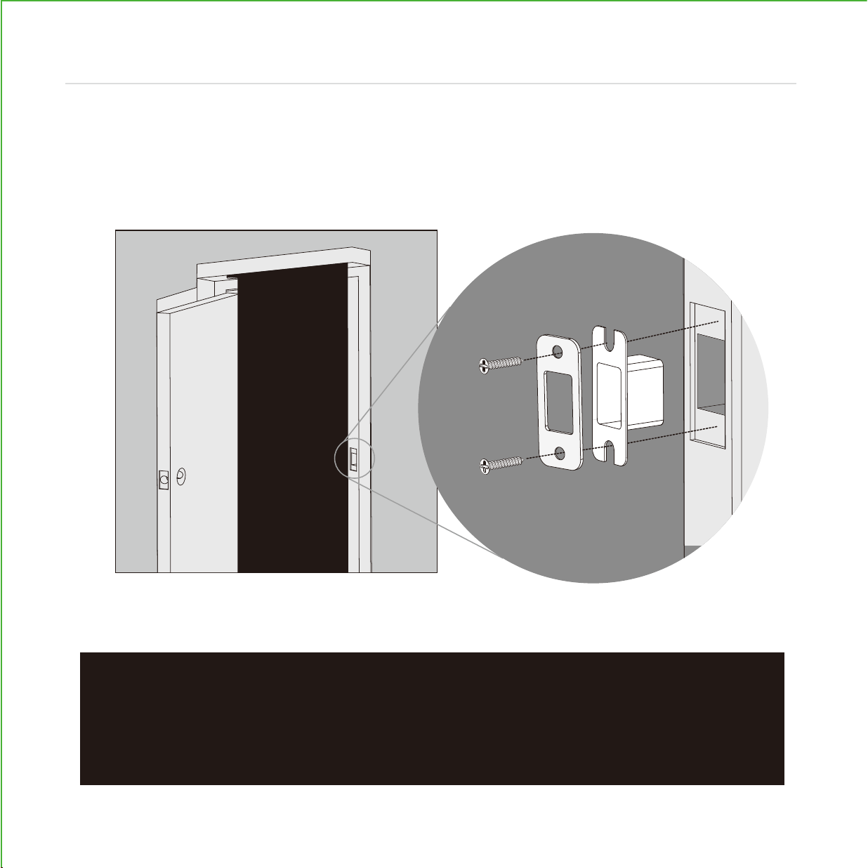
Use the supplied door strike or use your existing as long as deadbolt operates smoothly
without binding or catching.
IMPORTANT: because doors and frames vary in design it may be necessary to
make slight adjustments to your strike plate and/or dust box in order to ensure
smooth deadbolt operation. This is very important. If the deadbolt is binding or
catching in any way the lock will sound an alarm (rapid beeping) indicating it
cannot close due to misalignment and/or excessive rubbing or binding.
17
INSTALLING STRIKE PLATE
Step 8
L
K(2X)
N
18
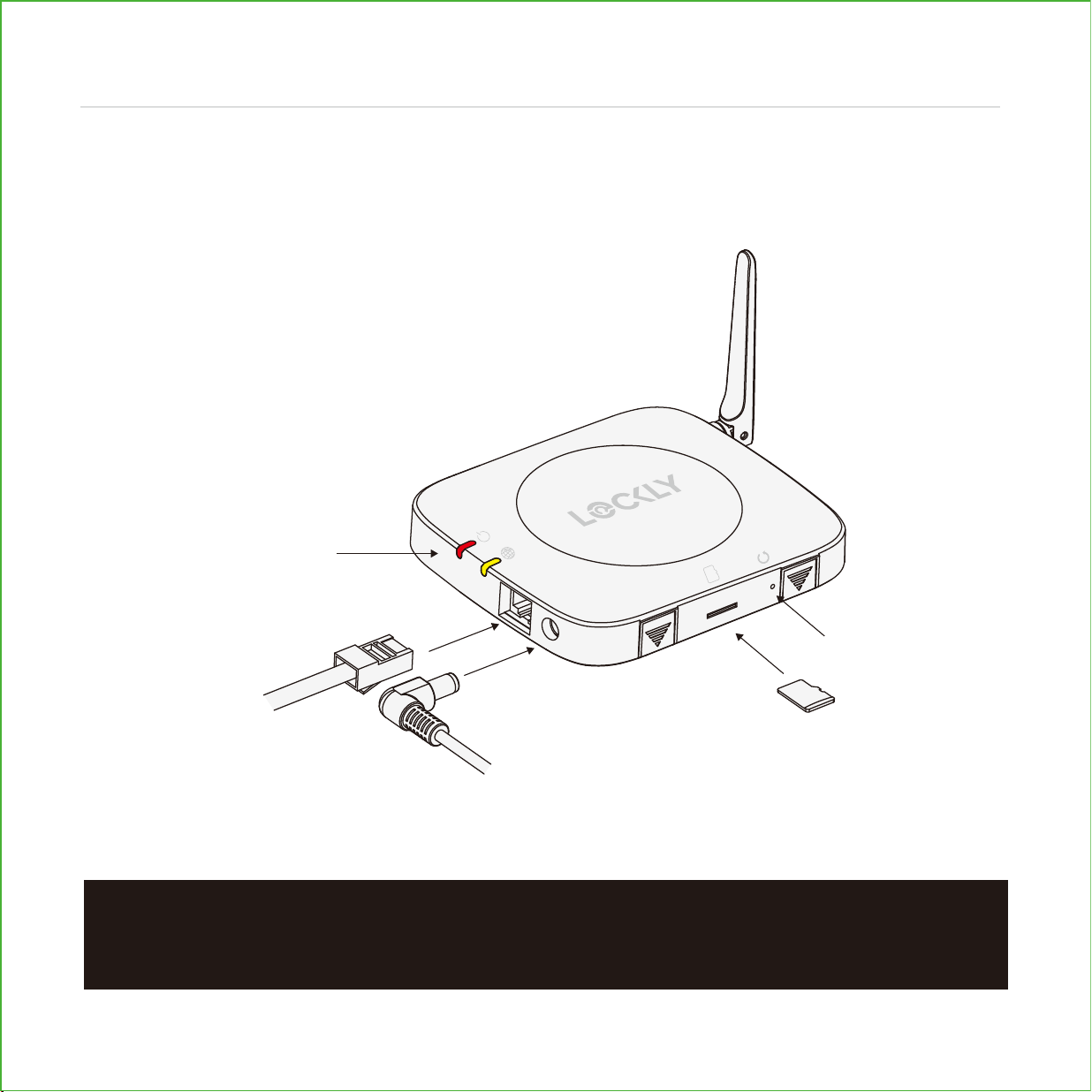
To enable video doorbell, live monitoring and voice control with Hey Google and Alexa,
you will need to setup the included Vision Connect Wi-Fi hub with the Lockly Vision™
deadbolt smart lock + video doorbell.
IMPORTANT: Vision Connect stores recorded video on the included TF card. Although
the TF card is discrete, it is recommended to locate it in a discrete or secure area to
protect your privacy and video recordings.
SETUP THE HUB
LED status lights
Antenna
VISION CONNECT OVERVIEW
LAN cable
Power adapter
TF card
Reset
Step 9
LOCKLY.COM | HOTLINE: +1(669) 500-8835 | EMAIL: [email protected]
ACC20211201
KEEP THIS CARD!
ACTIVATION CARD
LOCKLY APP & UNIQUE ACTIVATION CODE
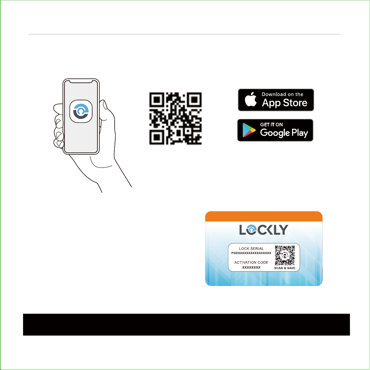
Before connecting Vision Connect Hub download the Lockly app on your smartphone.
It’s required to finish and setup the connection between hub and lock.
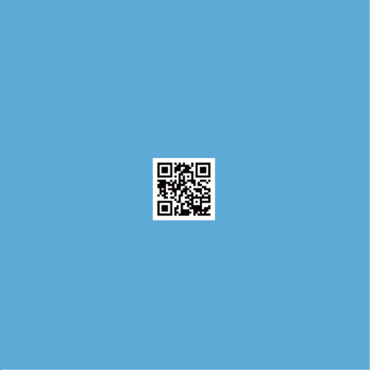
Scan, visit app store, or go to Lockly.com/app
IMPORTANT:
Without the QR code you will not be able to reset your lock
19
Step 9
continued
Additionally, you'll need the Activation Card
with unique pre-paired QR code to your lock.
The card is located in the packaging that your
lock came in. This QR code can also be found at
the bottom of Vision Connect Hub. Please keep
it in a safe place—this QR code is required to
complete the setup and will be required if you
lose your smartphone or access code.

Set up an account by registering your Lockly Vision
TM
in the Lockly app. Registration is also
mandatory to activate your locks warranty.
After successful registration, select "add a new device" (you can also get to this from the
menu in the top left), select Vision, and follow the step-by-step on screen instructions.
You can also reference these steps on following pages.
1 2 3
4 5 6
APP SET UP
Step 9 continued
20
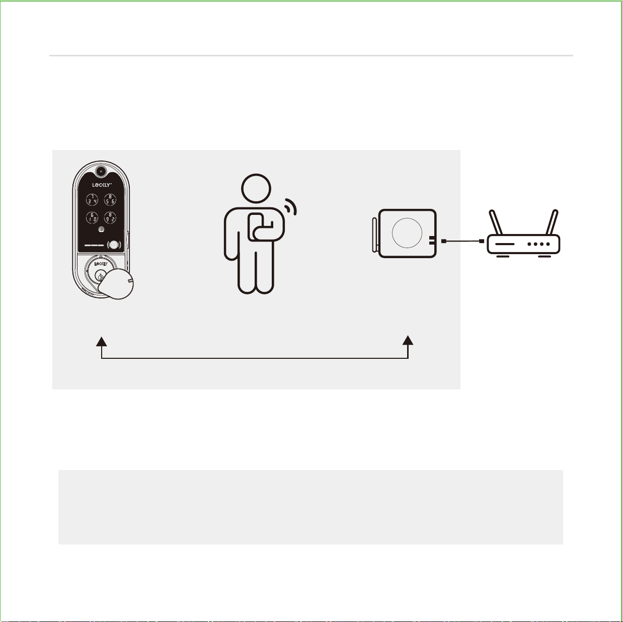
The Vision Connect Hub connects directly to your Wi-Fi router using the provided LAN
cable. Choose an appropriate location for the hub for optimum performance (see
below). For optimum connectivity, it is recommended to set up the hub LESS than 100
feet (30 meters) away from the lock, and elevated 3 feet (1 meter) off the ground.
During the setup process position yourself between the lock and the Vision Connect
hub—ideally no more than 100 feet (30 meters) apart. Ensure your iOS or Android
TM
device has both Bluetooth
®
and Wi-Fi enabled,
TIP:
Sometimes distances between hub and lock can vary due to circumstances.
If you are having difficulty setting up optimal range of 100/ft or less, we’re here to
help. Call our customer care team: (669) 500 8835, or visit Lockly.com/help for
suggestions and troubleshooting tips.
LOCATION GUIDELINES
100 Feet
(30 meters) or less
Lockly Vision
TM
You Vision Connect Wi-Fi Router
3 feet (1 meters)
off the ground
21
Step 9
continued

Ensure the TF card that comes with
Vision Connect is properly inserted.
TF card (included, inserted)
Connect LAN cable to closest Wi-Fi router
to the Lockly Vision
TM
lock (<100ft).
LAN cable (S) (included)
Connect power cable and plug
USB power adapter into outlet.
VISION CONNECT HUB SETUP
Wait 2 minutes for hub to self calibrate.
Once LEDs turn RED and blink yellow.
Vision Connect is now ready to connect to your iOS or Android
TM
device.
See troubleshooting on next page if LEDs do not meet the described conditions.
22
Step 10
continued
Always keep the Antenna
on UP position

LOCKLY.COM | HOTLINE: +1(669) 500-8835 | EMAIL: [email protected]
ACC20211201
KEEP THIS CARD!
ACTIVATION CARD
IMPORTANT:
make sure your Lockly Vision has the latest firmware. Allow updates and
follow instructions if prompted. For more info, visit: http://www.support.Lockly.com/-
faq/firmware-update/
TIPS:
• Remember to register for warranty.
• Allow your mobile phone to receive push notifications.
• Send in-app feedback if you encounter any issues while using the App.
• If you are having difficulty scanning the QR code, we’re here to help. Call our
customer care team: (669) 500 8835, or visit Lockly.com/help for suggestions and
troubleshooting tips.
NOTE: Power interruption during firmware update may damage the Vision Connect hub.
Do not interrupt or turn the power off while firmware update is in progress.
Launch the Lockly
App and select "add a new device", then select Vision. You will be prompted
to scan the QR code from the Activation Card or Vision Connect Hub (located at the bottom).
PAIR VISION LOCK TO APP
23
Step 10
continued
LOCKLY
App
OR
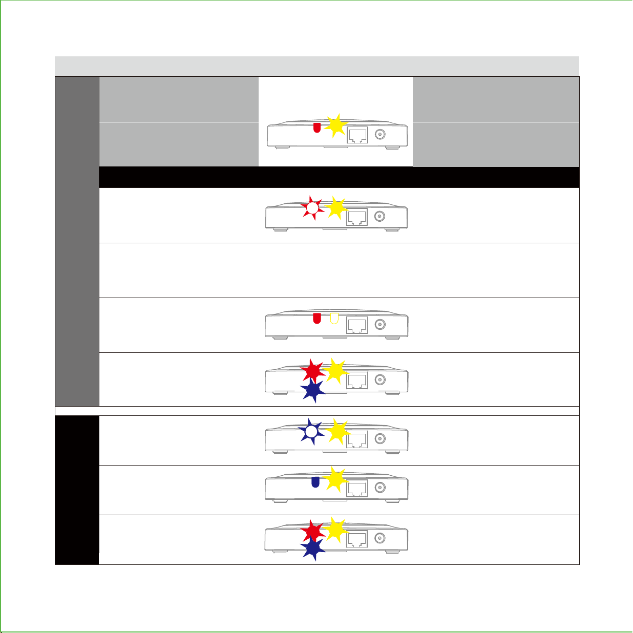
READY TO CONNECT
Solid red ON
During Setup
Power ON/
Successfully paired
Network connected
Pairing / Network
NOT yet connected
Pairing unsuccessful
Router or LAN cable issue
NO network connection
Resetting
Yellow slow blinking
Red slow blinking
Red fast blinking
Yellow OFF
Blinking red goes to blue,
then turns OFF
Blue slow blinking
Update in progress
*
Update Successful
Update has failed
Blue ON
Blinking from red to blue
After connecting LAN cable and
power adapter, wait for 2mins for
Vision Connect to self calibrate.
During Firmware Update
LED INDICATORS HUB
STATUS
*Power interruption during firmware update may damage the Vision Connect hub.
Do not interrupt or turn the power off while firmware update is in progress.
24
VISION CONNECT STATUS & TROUBLESHOOTING
If you experience any of the following, power down and disconnect hub, repeat connection process

“Alexa, is my Front Door locked?”
“Your Front Door is locked”
To setup your lock to work with either
voice assistant, download the Amazon
Alexa or Google Home App and add a
new Amazon Alexa Skill or Lockly Action
on Google.
Google, Android, Google Play and Google Home are trademarks of Google LLC.
Hands-free voice control
Control and check your status using only your voice with Amazon Alexa or Google
Assistant-enabled devices.
TIP:
In Google Home or Amazon Alexa app, add Lockly skill for Alexa or Lockly Action
on Google, then follow on screen instructions. See full list of commands, help videos, or
troubleshooting your Lockly at https://Lockly.com/help
VOICE CONTROL
Smart Home Ready
25

FCC Warning:
This device complies with Part 15 of the FCC Rules. Operation is subject to the following two conditions: (1) This device may
not cause harmful interference, and (2) this device must accept any interference received, including interference that
may cause undesired operation.
NOTE 1: This equipment has been tested and found to comply with the limits for a Class B digital device, pursuant to part 15
of the FCC Rules. These limits are designed to provide reasonable protection against harmful interference in a residential
installation. This equipment generates, uses and can radiate radio frequency energy and, if not installed and used in accordance
with the instructions, may cause harmful interference to radio communications. However, there is no guarantee that
interference will not occur in a particular installation. If this equipment does cause harmful interference to radio or television
reception, which can be determined by turning the equipment off and on, the user is encouraged to try to correct the
interference by one or more of the following measures:
- Reorient or relocate the receiving antenna.
- Increase the separation between the equipment and receiver.
- Connect the equipment into an outlet on a circuit different from that to which the receiver is connected.
- Consult the dealer or an experienced radio/TV technician for help.
NOTE 2: Any changes or modifications to this unit not expressly approved by the party responsible for compliance could
void the user's authority to operate the equipment.
FCC Radiation Exposure Statement
Lockly Vision complies with FCC radiation exposure limits set forth for an uncontrolled environment. It should be installed
and operated with minimum distance 20cm between the radiator & your body.
IC WARNING
This device contains license-exempt transmitter(s) that comply with Innovation, Science and Economic Development Canada’s
licence-exempt RSS(s). Operation is subject to the following two conditions:
(1) This device may not cause interference.
(2) This device must accept any interference, including interference that may cause undesired operation of the device.
L’émetteur/récepteur exempt de licence contenu dans le présent appareil est conforme aux CNR d’Innovation, Sciences
et Développement économique Canada applicables aux appareils radio exempts de licence. L’exploitation est autorisée
aux deux conditions suivantes:
1. L’appareil ne doit pas produire de brouillage;
2. L’appareil doit accepter tout brouillage radioélectrique subi, même si le brouillage est susceptible d’en compromettre
le fonctionnement.
IC Radiation Exposure Statement
This equipment meets the exemption from the routine evaluation limits in section 2.5 of RSS-102. It should be installed and
operated with a minimum distance of 20cm between the radiator and any part of your body.
Cet équipement est conforme à l'exemption des limites d'évaluation habituelle de la section 2.5 de lanorme RSS-102. Il doit
être installé et utilisé à une distance minimale de 20 cm entre le radiateur et toute partie de votre corps.
WARNING: This product can expose you to chemicals including Lead, which is known to the State of California to
cause cancer. For more information go to www.P65Warnings.ca.gov.
Adhesive TAPE
LOCKLY.COM | HOTLINE: +1(669) 500-8835 | EMAIL: [email protected]
ACC20211201
KEEP THIS CARD!
ACTIVATION CARD
Lockly Vision
TM
can be fitted for both right swing doors and left swing doors.
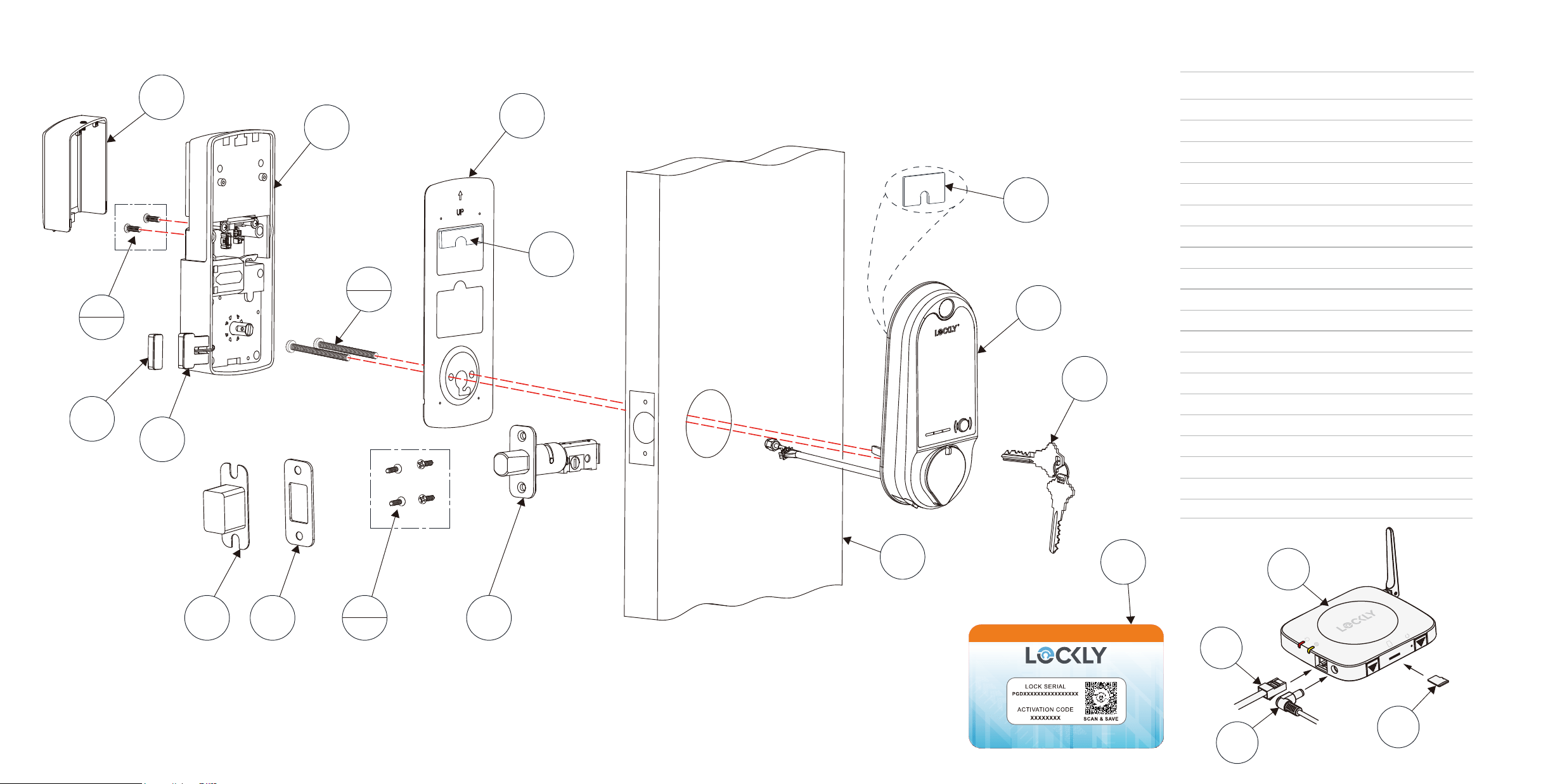
INSTALLATION OVERVIEW AND PARTS LIST
A
B
S
U
T
C
D
G
I
H
2x
J
K
4x
L
N
P
Q
E
E
F
2x
Parts List
Labeled As Description
A Keys
B Exterior Assembly
C Exterior
D Mounting Plate
E Adhesive
F PM5×60mm Screw
G Interior Assembly
H PM4*12MM Screw
I Battery Cover
J Deadbolt
K KA4*20MM Screw
L
Strike Plate
N Dust Box
P
Wired Sensor
Q
R
S
T
Sensor Magnet
Vision Connect
LAN Cable
Power Plug
U
TF Card
V
Activation Card
R
Adhesive TAPE
V

@meetlockly | #Lockly
Connect with us
Reference installation parts overview foldout.

VISION
™
IMPGD79820220609
We’re here to help!
Email: [email protected]
Lockly.com/help
For the most up to date version of this guide please visit:
© Copyright 2022 Lockly All rights reserved
USA Patent No. US 9,881,146 B2 | USA Patent No. US 9,853,815 B2 | USA Patent No. US 9,875,350 B2 | USA
Patent No. US 9,665,706 B2 | USA Patent No. US 11,010,463 B2 | AUS Patent No. 2013403169 | AUS Patent No.
2014391959 | AUS Patent No. 2016412123 | UK Patent No. EP3059689B1 | UK Patent No. EP3176722B1 |
Multiple Patents Pending The Bluetooth
®
word mark and logos are registered trademarks owned by the
Bluetooth SIG, Inc. , and any use of such marks by Lockly is under license. Other trademarks and trade names
are those of their respective owners. Google, Android, Google Play and Google Home are trademarks of
Google LLC. , and all related logos are trademarks of Amazon.com, Inc., or its affiliates.