Operating Instructions
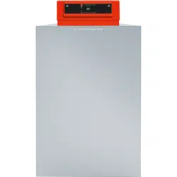
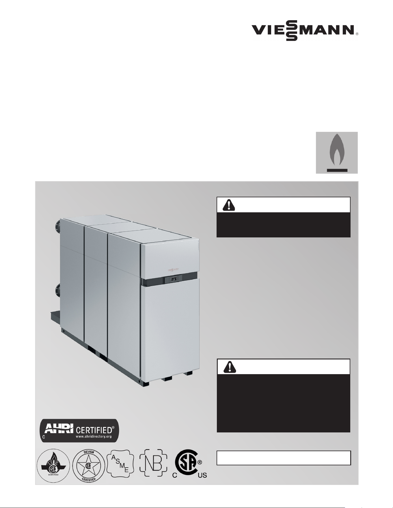
VITOCROSSAL 300
5838 950 - 03 01/2023
for use by heating contractor
Vitocrossal 300 CA3B Series 2.5, 3.0, 3.5, 4.0, 5.0 and 6.0
with Vitotronic 300 GW6C control (with Graphical User Interface HI932)
Gas condensing boiler with weather-compensated control unit
Read and save these instructions for
future reference.
Please file in Service Binder
Heating input: 2500 to 6000 MBH
(733 to 1758 kW)
Product may not be exactly as illustrated.
Do not store or use gasoline or other
ammable liquids in the vicinity of this
or any other appliance.
WHAT TO DO IF YOU SMELL GAS
g Do not try to light any appliances.
g Do not touch any electrical switches,
do not use any phone in your building.
g Immediately call your gas supplier
from a neighbor’s phone. Follow
the gas supplier’s instructions.
g If you cannot reach your gas supplier,
call the re department.
Installation and service must be
performed by a qualied installer,
service agency or the gas supplier.
WARNING
If the information in this manual is not followed
exactly, a fire or explosion may result causing
property damage, personal injury or loss of life.
WARNING
Improper installation, adjustment, and/
or operation could cause carbon monoxide
poisoning resulting in injury or loss of life.
This product must be installed and serviced
by a professional service technician who is
experienced and qualified in hot water boiler
installation and gas/oil combustion.
H
IMPORTANT
2
5838 950 - 03
Vitocrossal 300 CA3B Series 2.5 to 6.0 Operating
Safety, Installation and Warranty Requirements
Please ensure that these instructions are read and understood before commencing installation. Failure to comply with
the instructions listed below and details printed in this manual can cause product/property damage, severe personal
injury, and/or loss of life. Ensure all requirements below are understood and fulfilled (including detailed information
found in manual subsections).
General Information
WARNING
Installers must follow local regulations with respect
to installation of carbon monoxide detectors. Follow
the Viessmann maintenance schedule of the boiler
contained in “Service Instructions”.
g Product documentation
Read all applicable documentation before commencing
installation. Store documentation near boiler in a
readily accessible location for reference in the future
by service personnel.
uFor a listing of applicable literature,
please see section entitled “Important
Regulatory and Safety Requirements”.
g Warranty
Information contained in this and
related product documentation must
be read and followed. Failure to do
so renders the warranty null and void.
g Licensed professional heating contractor
The installation, adjustment, service and maintenance
of this equipment must be performed by a licensed
professional heating contractor.
uPlease see section entitled
“Important Regulatory and Installation
Requirements”.
g Contaminated air
Air contaminated by chemicals can cause by-products
in the combustion process, which are poisonous to
inhabitants and destructive to
Viessmann equipment.
uFor a listing of chemicals which
cannot be stored in or near the
boiler room, please see subsection
entitled “Mechanical Room”.
g Advice to owner
Once the installation work is complete, the heating
contractor must familiarize the system operator/
ultimate owner with all equipment, as well as safety
precautions/requirements, shutdown procedure, and
the need for professional service annually before the
heating season begins.
g Carbon monoxide
Improper installation, adjustment, service and/or
maintenance can cause flue products to flow into
living space. Flue products contain poisonous carbon
monoxide gas.
uFor information pertaining to the
proper installation, adjustment, service
and maintenance of this equipment to
avoid formation of carbon monoxide,
please see sections entitled
“Mechanical Room” and “Venting
Connection” in the Installation Instructions.
g Fresh air
This equipment requires fresh air for
safe operation and must be installed
ensuring provisions for adequate
combustion and ventilation air exist.
uFor information pertaining to the
fresh air requirements of this product,
please see subsection entitled
“Mechanical Room”.
g Equipment venting
Never operate boiler without an installed venting
system. An improper venting system can cause
carbon monoxide poisoning.
uFor information pertaining to
venting and chimney requirements,
please see section entitled “Venting
Connection”. All products of
combustion must be safely vented
to the outdoors.
3
5838 950 - 03
Vitocrossal 300 CA3B Series 2.5 to 6.0 Operating
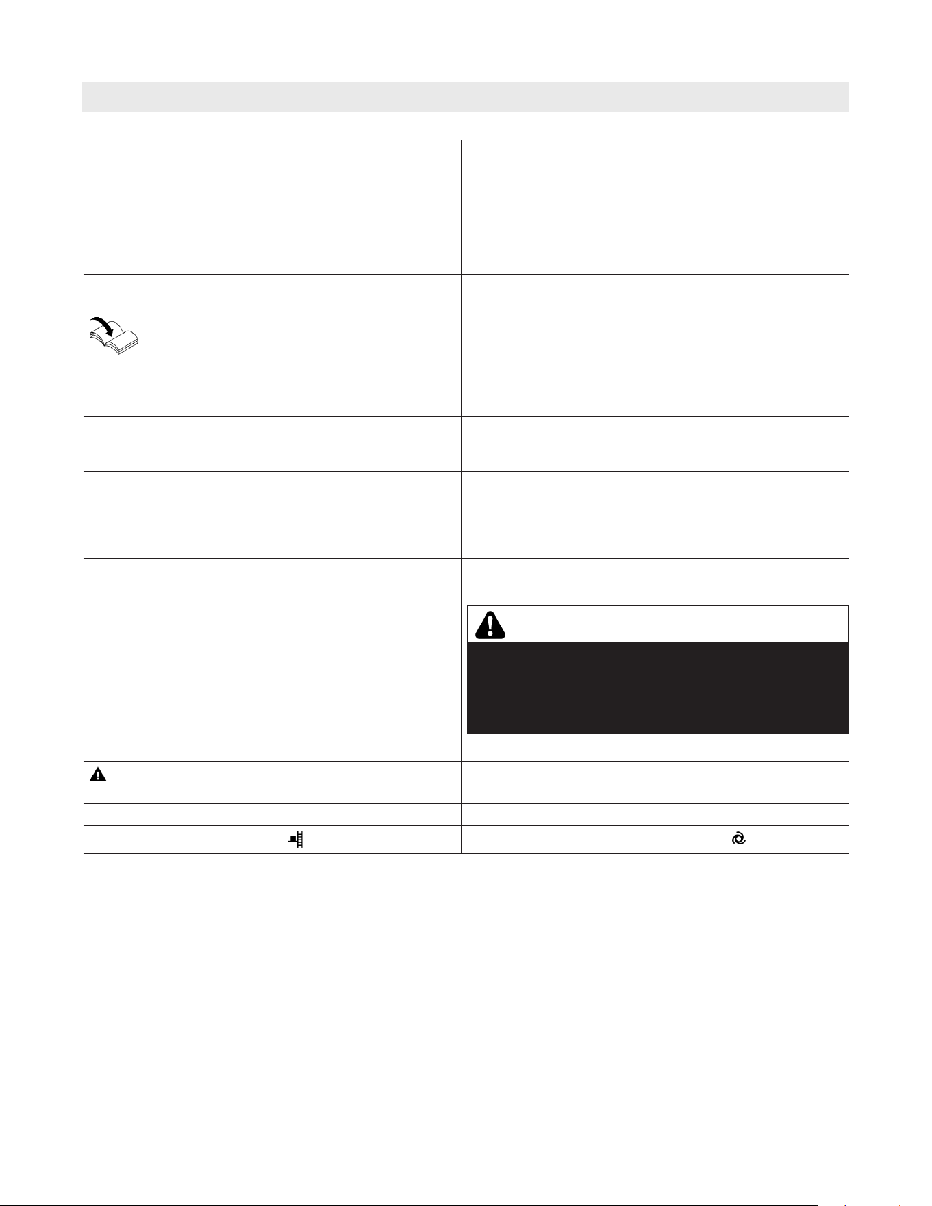
About these Instructions
Take note of all symbols and notations intended to draw attention to potential hazards or important product
information. These include “WARNING”, “CAUTION”, and “IMPORTANT”. See below.
u
IMPORTANT
uWarnings draw your attention to the presence of
potential hazards or important product information.
u
Cautions draw your attention to the presence of
potential hazards or important product information.
u
Helpful hints for installation, operation or maintenance
which pertain to the product.
u
This symbol indicates that additional, pertinent
information is to be found.
u
This symbol indicates that other instructions must
be referenced.
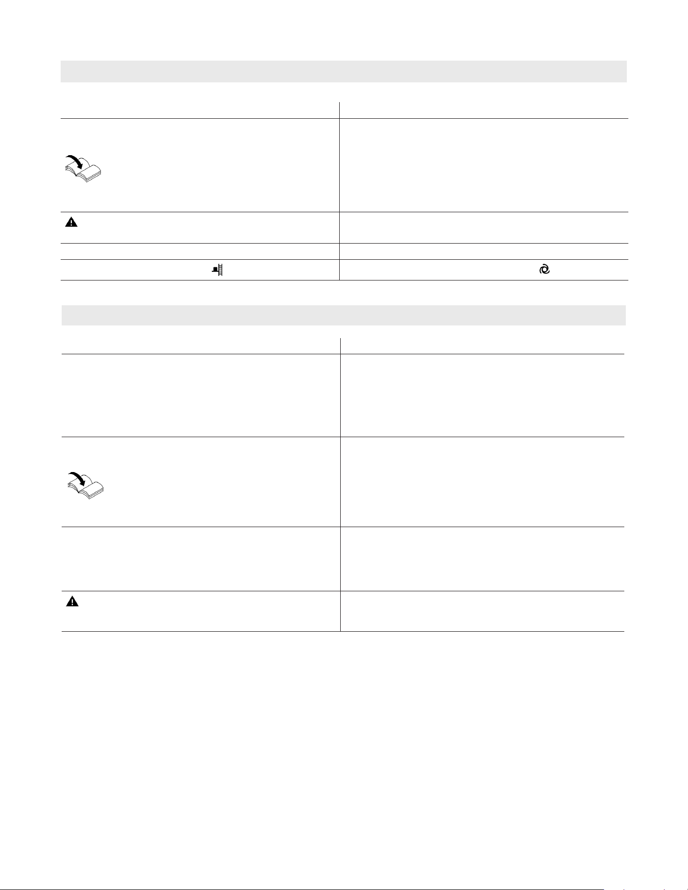
General Information
WARNING
Indicates an imminently hazardous situation which,
if not avoided, could result in death, serious injury
or substantial product/property damage.
CAUTION
Indicates an imminently hazardous situation which,
if not avoided, may result in minor injury or product/
property damage.
Product Information
WARNING
Exposing the boiler to pressures and temperatures in
excess of those listed will result in damages, and will
render warranty null and void.
The Viessmann Vitocrossal 300, CA3B boiler series is
CSA certified for Canada, is constructed in compliance
with CSA B51 Standard and carries Canadian Registration
Numbers. The boiler is suitable for a maximum operating
pressure of 160 psig and a maximum boiler water
temperature of 210°F (99°C).
The Vitocrossal 300, CA3B boiler must only be installed
in closed loop hot water heating systems using a
pre-charged membrane expansion tank.

4
5838 950 - 03
Vitocrossal 300 CA3B Series 2.5 to 6.0 Operating
Table of Contents
Safety, Installation and Warranty Instructions ............... 2
About these Instructions ............................................ 3
Product Information ................................................... 3
For your Safety ......................................................... 6
Operation ................................................................. 6
Gas Smell ............................................................. 6
Flue gas Smell ...................................................... 6
Dangerous conditions ............................................ 6
Working on the Equipment ..................................... 6
Combustion air and ventilation openings ................... 6
Carbon monoxide .................................................. 6
Frozen water pipe hazard ....................................... 7
Boiler room conditions ........................................... 7
Maintenance and cleaning ...................................... 8
Regular maintenance and service ............................. 8
Technical information ............................................ 8
Description ............................................................... 9
Fuel ....................................................................10
Boiler control .......................................................10
Condensate disposal .............................................10
Boiler location ......................................................10
Venting connection ..............................................10
Optimum operation ...............................................10
Operation ................................................................11
Starting the heating system ...................................11
Separate heating system controls ...........................11
Domestic hot water production ..............................11
System shutdown ................................................11
Commissioning ................................................... 12
Your System is Preset at the Factory ..........................12
Energy Saving Tips ...................................................13
Tips for Greater Comfort ........................................... 13
General Boiler Information .........................................14
System and Lead Control Boiler Section 1
Programming Unit ....................................................15
Service Display Lag Boiler Sections ............................16
Starting the Heating System ....................................17
Shutting Down the Heating System ............................18
Operating Program ...................................................18
General Information
Safety
System Information
Operation
Page

5
5838 950 - 03
Vitocrossal 300 CA3B Series 2.5 to 6.0 Operating
Table of Contents
Central Heating
DHW Heating
Further Adjustments
Scanning
Scanning Options
Emissions
Troubleshooting
Maintenance
Additional Information
Page
Time Program ..........................................................19
Room Temperature ...................................................21
Operating Program ...................................................22
Time Program ..........................................................22
Heating Curve ..........................................................23
Stopping Central Heating ..........................................23
Comfort Function ........................................... .......... 24
Energy Saving Function “Economy Mode” ...................25
Energy Saving Function “Holiday Program” ..................26
DHW Temperature ....................................................27
Operating Program ...................................................27
Time Program ..........................................................27
Setting the Display Backlighting .................................29
Naming Heating Circuits ............................................ 29
Setting the Time and Date ........................................29
Language Selection ..................................................30
Setting the Measuring Units .......................................30
Restoring Factory Settings .........................................30
Scanning Information ................................................ 31
Main Menu Overview ................................................ 34
Scanning Options under “Information” ........................36
Emissions Test Mode ................................................37
Rooms are Too Cold ................................................38
Rooms are Too Hot ..................................................39
There is No DHW ....................................................39
The DHW is Too Hot ................................................40
“Fault” will be Displayed ...........................................40
“Service” will be Displayed ........................................40
Inspection and Maintenance ......................................41
Service Schedule ......................................................41
Additional Maintenance Information ............................ 42
Terminology ............................................................42
6
5838 950 - 03
Vitocrossal 300 CA3B Series 2.5 to 6.0 Operating
For your Safety
g Working on the equipment
All personnel working on the equipment or the heating
system must have the proper qualifications and hold all
necessary licenses.
Ensure main power to equipment, heating system, and
all external controls have been deactivated. Close main
gas supply valve. Take precautions in all instances to
avoid accidental activation of power during service
work.
g Combustion air and ventilation openings
Ensure that combustion air openings and ventilation
air openings in the mechanical room are open.
g Carbon monoxide
The U.S. Consumer Product Safety Commission
strongly recommends the installation of carbon
monoxide detectors in buildings in which gas-burning
equipment is installed. Carbon monoxide (CO) is a
colorless, odorless gas, which may be produced during
incomplete combustion of fuel and/or when the flame
does not receive an adequate supply of combustion air.
Carbon monoxide can cause severe personal injury or
loss of life.
Therefore, carbon monoxide detectors that are in
compliance with a nationally recognized latest standard
(e.g. ANSI/UL 2034, CSA 6.19-01) should be installed
and maintained in buildings that contain gas-burning
equipment.
Note: Viessmann does not test any detectors and
makes no representation regarding any brand
or type of detector.
Incomplete combustion and poisonous gases result if the
fresh air intakes in the mechanical room are closed. Never
close these openings.
CAUTION
g Operation
Before operating the boiler, make sure you fully
understand its method of operation. Your heating
contractor should always perform the initial start-up
and explain the system. Any warranty is null and
void if these instructions are not followed.
g Gas smell
Follow the instructions on the front of the manual.
g Flue gas smell
- Deactivate heating equipment.
- Open windows and doors.
- Inform your heating contractor immediately.
g Dangerous conditions
- Deactivate main power immediately
- Close gas supply valve
CAUTION
Follow these safety instructions closely to avoid the risk
of injury and damage to property.
In emergencies
g Immediately switch off the power supply, e.g. at the
separate fuse or power supply disconnect switch
(unless there is a smell of gas).
g Close the shut-off valves in the oil pipes or close the
gas shut-off valve, whichever applicable.
g Use suitable extinguishers in the event of fire.
Safety
WARNING
This product burns gas to produce heat. The appliance
must be properly installed, operated and maintained
to avoid exposure to appreciable levels of carbon
monoxide and the installer is required to confirm that
at least one carbon monoxide alarm is installed in the
living space before the appliance is put into operation.
It is important for the carbon monoxide alarms to be
installed, maintained, and replaced following the alarm
manufacturer’s instructions and applicable local codes.
7
5838 950 - 03
Vitocrossal 300 CA3B Series 2.5 to 6.0 Operating
Safety
For your Safety (continued)
WARNING
The boiler must not be located in areas or rooms
where chemicals are stored, or aggressive vapors
from (i.e. bleach, hair spray, methyl chloride, carbon
tetrachloride or perchloroethylene) or high dust levels
or humidity levels are present. Heat exchanger
corrosion might occur and reduce the lifetime of the
boiler significantly. If above criteria are not properly
observed and boiler damage results, any warranty on
the complete boiler and related components will be
null and void.
IMPORTANT
Keep boiler and boiler room clear and free from combustible
materials, gasoline and other flammable vapors and liquids.
Do not obstruct the flow of combustion and ventilation air.
All inspection, maintenance and service must be performed
by a qualified heating contractor.
g Boiler room conditions
- Do not use a room in which the air is polluted by
halogenated hydro-carbons (e.g. as contained in aerosols,
paints, solvents and cleaning agents)
- Do not use a room subject to high levels of dust
- Do not use a room subject to permanently high humidity
- The room should be frost-protected
- Max. ambient temperature 95°F (35°C).
- Provide good ventilation and do not close or obstruct
vents (if installed).
g Frozen water pipe hazard
Your heating boiler is designed to provide a warm and
comfortable living environment. It is NOT designed to
ensure against freezing of water pipes.
The boiler is equipped with several safety devices that are
designed to shut down the boiler and to prevent it from
restarting in the event of various unsafe conditions.
If your boiler remains off for an extended period of time
during cold weather, water pipes may freeze and burst,
resulting in extensive water damage and conditions in
which mold could grow. Certain molds are known to
cause respiratory problems, as well as to pose other
serious health risks. In case of water damage, immediate
measures should be taken to dry out affected areas as
quickly as possible to prevent mold from developing.
If your home will be unattended for an extended period
of time during cold weather, you should...
- Shut off the water supply to the building, drain the
water pipes and add an antifreeze for potable water
to drain traps and toilet tanks. Open faucets where
appropriate.
or...
- Have someone check the building frequently during
cold weather and call a qualified service agency if
required.
or...
- Install a reliable remote temperature sensor that will
notify somebody of freezing conditions within the
home.
WARNING
Failure to protect against frozen pipes could result in
burst water pipes, serious property damage and/or
personal injury. Boiler may shut down. Do not leave
your home unattended for long periods of time during
freezing weather conditions without turning off the
water supply and draining water pipes or otherwise
protecting against the risk of frozen pipes.
Installation of additional components
The installation of additional components which have not
been tested together with the boiler can adversely affect
the function and performance of the boiler.
Our warranty does not cover and we accept no liability
for damage attributable to the installation of such
components.
8
5838 950 - 03
Vitocrossal 300 CA3B Series 2.5 to 6.0 Operating
WARNING
Improper installation, adjustment, service, or
maintenance can cause flue products to flow into
living space. Flue products contain poisonous carbon
monoxide gas which can cause nausea or asphyxiation
resulting in severe personal injury or loss of life.
WARNING
As there are no user-serviceable parts on the boiler,
burners or control, the end-user must not perform
service activities of any kind on system components.
Failure to heed this warning can cause property
damage, severe personal injury, or loss of life.
WARNING
Do not use this boiler if any part has been under or
exposed to water. Immediately call a qualified heating
contractor to inspect the boiler and to replace any part
of the control system and any gas control which has
been under, or exposed to, water.
g Maintenance and cleaning
Regular inspection and service by a qualified heating
contractor is important to the performance of the
Viessmann Vitocrossal 300, CA3B boilers. Neglected
maintenance impacts on warranty; regular inspection
ensures clean, environmentally friendly and efficient
operation. We recommend a maintenance contract
with a qualified heating contractor.
g Regular maintenance and service
The entire heating system must be cleaned and
serviced on a regular basis by a qualified heating
contractor or service agency to ensure reliable,
energy-efficient, and environmentally friendly
operation.
The build-up of soot on the heat exchanger raises
the flue gas temperature and reduces efficiency.
Indirect-fired domestic hot water storage tanks (if
installed) should be serviced within two years (at
most) of the installation date, and regularly thereafter.
For an overview of scheduled service procedures,
please refer to section entitled “Service Schedule” on
page 41 of this manual.
The owner or dedicated personnel should perform
the checks outlined in the Service Schedule to ensure
proper operation of the heating system.
IMPORTANT
g Technical information
Literature applicable to the Vitocrossal 300, CA3B
boiler:
- Installation Instructions
- Service Instructions
- Operating Instructions
Keep all literature in a safe place at the installation site.
Contact Viessmann for additional copies.
For your Safety (continued)
Safety
CAUTION
Should overheating occur or the gas supply fail to
shut off, do not disconnect the electrical supply to the
pump. Instead, shut off the gas supply at a location
external to the appliance.
9
5838 950 - 03
Vitocrossal 300 CA3B Series 2.5 to 6.0 Operating
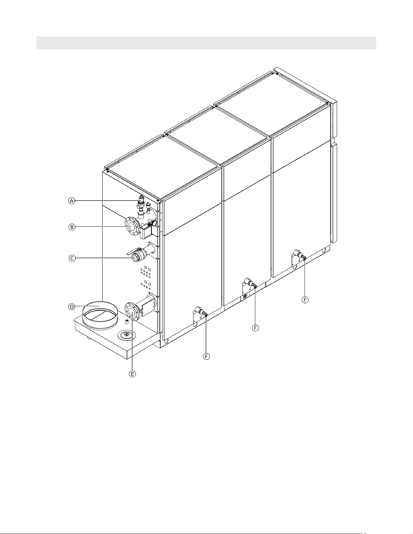
Description
System Information
Legend
A Safety header
B Boiler supply
C Gas connection
D Flue gas outlet (vent pipe connection)
E Boiler return
F Boiler drain
10
5838 950 - 03
Vitocrossal 300 CA3B Series 2.5 to 6.0 Operating
System Information
Description (continued)
Fuel
Natural gas (NG) or liquid propane gas (LPG).
Boiler control
The Vitocrossal 300, CA3B boiler series is operated with
a Vitotronic control and microcomputer indoor/outdoor
control system for boiler operation without low temperature
limit. The control system must be programmed for this type
of operation by the installing heating contractor.
Refer to the boiler Installation and Service
Instructions.
CAUTION
The boiler room must be safe from frost and be
properly ventilated.
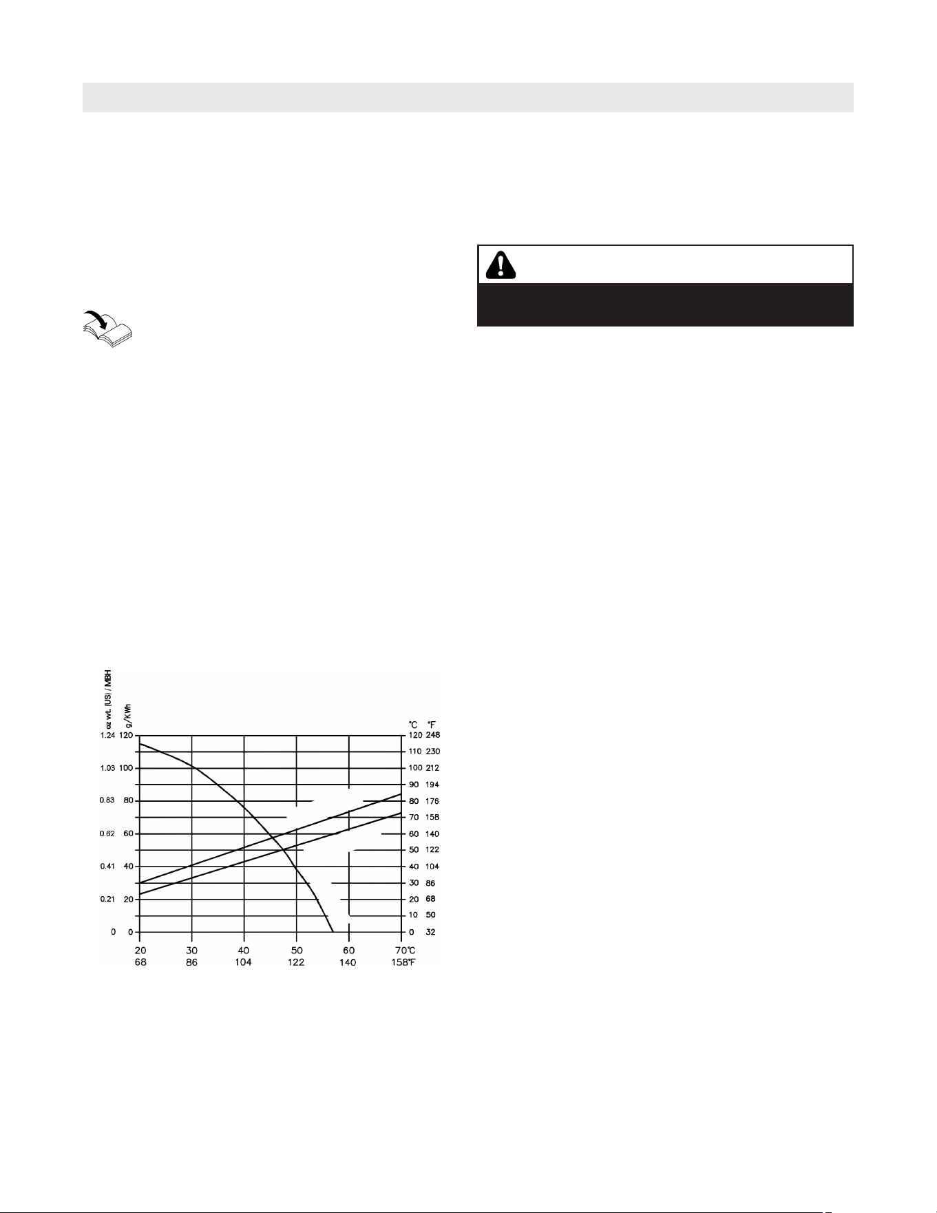
Condensate disposal
During the operation of the Vitocrossal 300 CA3B boiler,
the amount of condensate as per the diagram can be
expected.
The values given are approximate amounts occurring under
practical conditions. Not included in the chart is the amount
of condensate occurring in the vent pipe and chimney
system. The condensate from the chimney system can be
collected together with the condensate from the heating
boiler and be disposed of into a floor drain.
The condensate occurring will have a pH value between
3 and 4. If local building requirements demand neutralizing
the condensate before disposal, contact Viessmann
Manufacturing Company Inc. for a correctly sized
neutralization tank. The treated condensate will show pH
values of between 6.5 and 9 and can then be disposed of
into the waste water system.
Boiler location
The boiler must not be installed in rooms or areas where
halogenated hydrocarbons are present in the combustion
air, such as barber shops and beauty salons, printing
shops, chemical cleaners, laboratories etc.
Vitocrossal 300, CA3B boiler efficiency is dependent
on system heating water return temperatures and load
conditions.
Venting connection
A large amount of water vapor is contained in the flue
gases of a condensing boiler. The condensate pH value is
between 3 and 5.5. The flue gas temperatures depending
on the boiler water temperature may be between 77°F
(25°C) and 257°F (125°C).
The manufacturer of the chimney system or venting
system has to properly design the venting system as well
as select proper materials.
If there are any questions in regards to the neutralization
of the condensate and/or to the venting of this boiler
series, contact your local Viessmann Sales Representative.
Optimum operation
To ensure optimum operation of your heating system do
the following:
g Keep the boiler and the boiler room clean and free
of dust and dirt.
g Ensure proper and adequate system pressure by
occasionally checking the pressure gage.
g Have a qualified heating contractor service and
maintain your heating system on a regular basis.
For details refer to section entitled Service Schedule
on page 41.
Amount of condensate
Boiler water return temperature
Flue gas temperature gross
Flue gas temp.
at full input
at partial load
Flue gas temp.
Amount of
condensate
11
5838 950 - 03
Vitocrossal 300 CA3B Series 2.5 to 6.0 Operating
System Information
Operation
System shutdown
The boiler controls monitor the operation of your heating
system in conjunction with installed system controls (if
applicable) based upon indoor/outdoor control, setback
programming and other settings. Please refer to the
respective documentation of the boiler controls, or other
system controls, to make adjustments.
Deactivate main power switch and all additional switches
controlling additional pumps or controls, including main
switch for burners. Close all valves in the system.
Separate heating system controls
In case additional controls are installed in the boiler room,
e.g. control aquastats, mixing valves, controls etc.,
please observe their respective operating instructions.
Domestic hot water production
The Vitocrossal 300, CA3B boiler may be used to supply
domestic hot water heating by means of an indirect-fired
hot water storage tank. The appropriate connections
to the boiler must be made, as well as the correct size
circulating pump must be used. The control circuit to
provide domestic hot water is already provided within
the Vitotronic control.
Starting the heating system
Ask your heating contractor about the following:
g Boiler and relevant control unit type
g Level of the required system pressure
g Position of the pressure gauge, shutoff valve,
gas shut-off valve, ventilation apertures
1. Check the heating system pressure at the pressure
gauge. If the pressure of the heating system is too
low, top up the water or notify your heating
contractor.
2. Open the gas shut-off valve.
3. Switch ON the power supply,
e.g. at a separate MCB/fuse or a mains isolator.
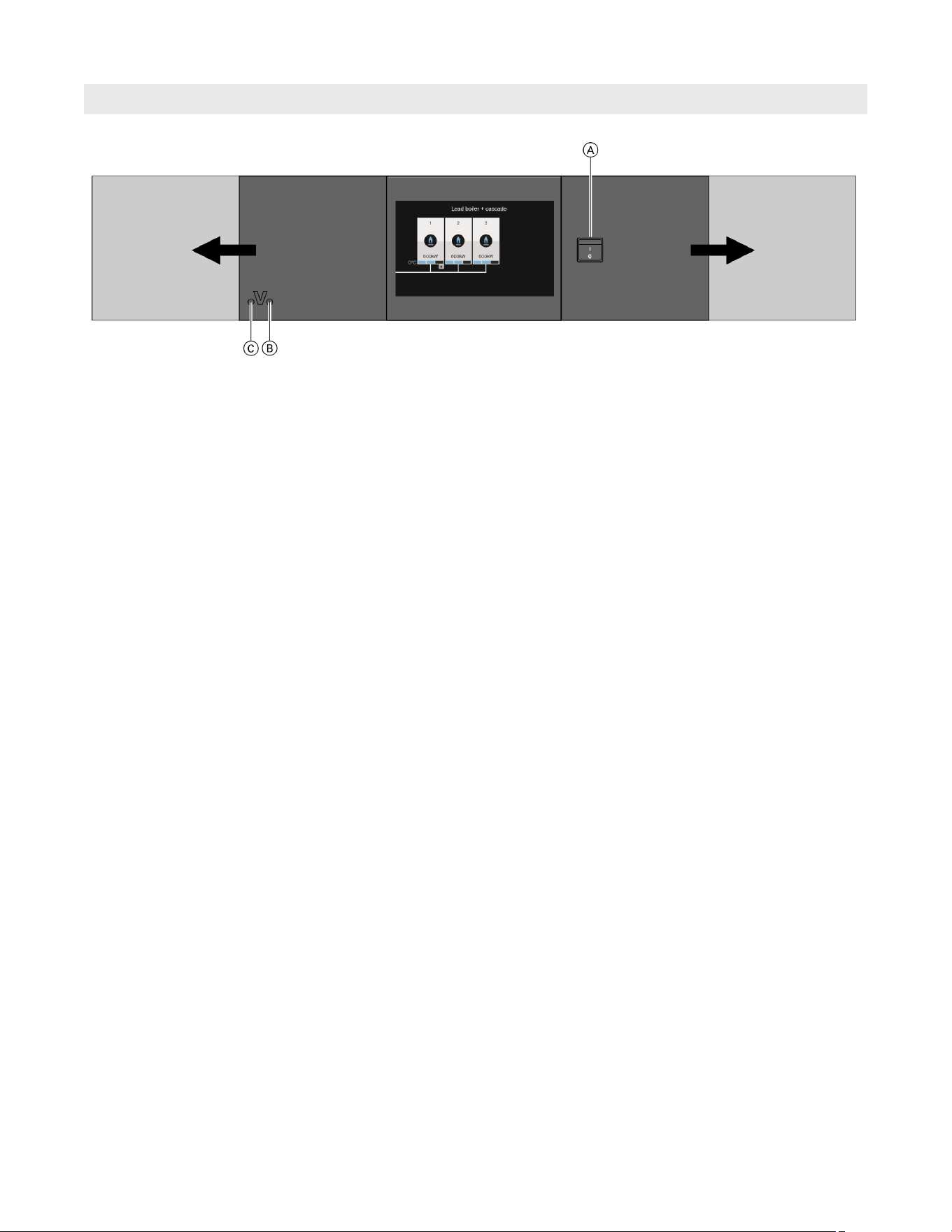
4. Switch the ON/OFF switch ON (see diagram).
After a short time, the home screen is displayed
and the green ON indicator illuminates.
Your heating system and, if installed, your remote
controls are now ready for use.
Legend
A ON/OFF switch
B ON indicator (green)
C Fault indicator (red)

12
5838 950 - 03
Vitocrossal 300 CA3B Series 2.5 to 6.0 Operating
Commissioning
System Information
As the user of new combustion equipment, you may be
obliged to notify your local service technician of the
installation [check local regulations]. Your local service
technician will also inform you [where appropriate] about
work he may be required to perform on your combustion
equipment (e.g. regular checks, cleaning).
The commissioning and matching of the control unit to
local conditions and building characteristics, as well as
instructing the user in the operation of the system, must
be carried out by the heating contractor.
Your System is Preset at the Factory
The Vitotronic 300 GW6C control comes shipped with
factory default settings that ensure secure operation
and provides basic operating functions. Upon powering
up the Vitocrossal 300, CA3B boiler and burners may
be initially commissioned or temporarily operated with
the factory default values. It is recommended that the
commissioning process is completed with either the
‘Commissioning Assistant’ (refer to the installation/service
instructions on ‘Commissioning the System’) or through
‘System Configuration’ in the service menu (refer to the
installation/service instructions on ‘calling up the service
menu’).
Your heating system is preset at the factory and is
therefore ready for operation:
Central heating
H Between 12:00 am and 12:00 am (00:00 h and 24:00 h),
the rooms are heated to 68°F (20°C) “Room temp set
point” (standard room temperature).
DHW heating
H Between 12:00 am and 12:00 am (00:00 h and 24:00 h)
DHW will be heated to 122°F (50°C) “DHW
temperature setpoint”.
Any installed DHW recirculation pump is switched on.
Frost protection
H Your boiler and DHW tank are protected against frost.
Daylight savings time
H This changeover is automatic.
Date and time
H The date and time were set by your heating contractor.
You can change these settings at any time to suit your
individual requirements.
Power failure
All settings are saved if there is a power failure.

13
5838 950 - 03
Vitocrossal 300 CA3B Series 2.5 to 6.0 Operating
System Information
H Holiday:
If you are going away, select the “Holiday program”:
The room temperature will be reduced, and DHW
heating will be turned off.
H Ventilation:
Close the thermostatic valves when ventilating.
Open the windows fully for a brief time.
H Roller shutters:
Close roller shutters (if installed) at dusk.
H Thermostatic valves:
Ensure that thermostatic valves are properly adjusted.
H Radiators:
Never cover radiators or thermostatic valves.
DHW heating
H DHW recirculation pump:
Only activate the DHW recirculation pump for periods
in which DHW is regularly drawn off. Set the time
program for this.
H DHW consumption:
Consider showering instead of running a bath. A
shower generally uses less energy than a full bath.
For additional energy saving functions of the Vitotronic
control unit, please contact your heating contractor.
Central heating
H Standard room temperature
(“Room temp target”):
Never overheat your home. Every degree of room
temperature reduction saves up to 6% on your heating
bills. Never set your standard room temperature higher
than 68°F (20°C).
H Time program:
Heat your home to the standard room temperature
during the day and the reduced temperature at night.
Set the time program for this.
H Operating program:
If you do not require central heating, select one of the
following operating programs:
– “DHW only”:
If you require no heating for your home in summer,
but you need hot water.
– “Standby mode”:
If you don’t need to heat your home and don’t need
hot water for long periods.
H Short absence:
Reduce the room temperature if you are going out
shopping, for example. For this, select “Economy
mode”.
Tips for Greater Comfort
Central heating
H Standard room temperature
(“Room temp set point”):
You can select your individual preferred temperature
at any time in the standard menu.
H Time program:
Make use of the time program. In the time program,
you can set time phases with different room
temperatures, for example different temperatures for
day and night time.
H Heating curve:
The heating curve enables you to individually adjust
the heating system to the actual heat demand in your
home.
If set correctly, your preferred temperature will be
achieved all year round.
H “Comfort mode”:
Select “Comfort mode” if you want to heat your
interior at a temperature that deviates from that
in a time program.
Example: Late in the evening, the reduced room
temperature is set by the time program.
Your guests stay longer.
DHW heating
H Time program:
Make use of the time program.
Energy Saving Tips
14
5838 950 - 03
Vitocrossal 300 CA3B Series 2.5 to 6.0 Operating
Operation
General Boiler Information
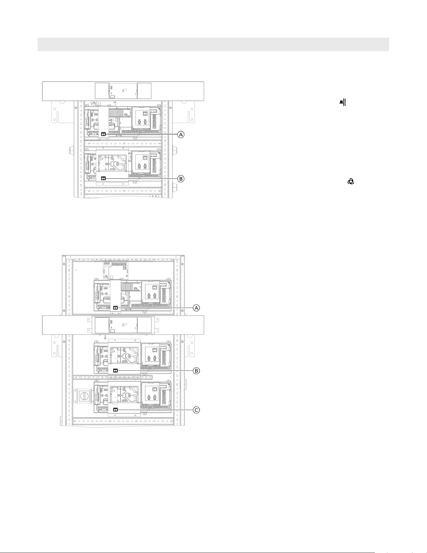
Multi boiler application
In a multi boiler application there can be a minimum of
4 boiler sections (e.g. two model 3.5 boilers) and a
maximum of 8 boiler sections (e.g. one model 4.0 and
two model 6.0 boilers).
For the 2nd boiler, A would be the next lag control in
sequence (e.g. if the 1st boiler ended with C lag 2 control,
section 3, then the 2nd boiler would start with lag 3 control,
boiler section 4 and will continue in sequence for this boiler
and the next.
All boiler sections are controlled and displayed through the
first boiler A lead control boiler section 1. For the 2nd
(3rd or 4th) boiler the lower front panel and control cover
are required to be opened to set up for the lag control.
Service and Emissions
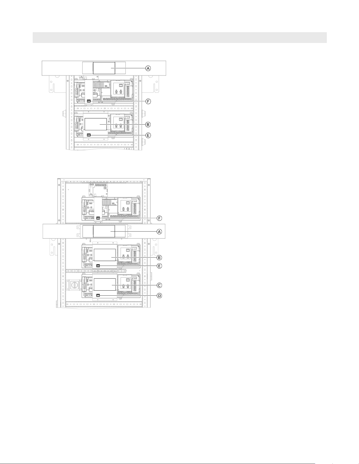
For all CA3B boilers B and C are used for lag boiler
section service displays. For the 2nd (3rd or 4th) boiler
A is used as a lag boiler section service display.
To respond to a service condition for B and C the
lower front boiler panel and control cover are required to
be opened. To respond to a service condition for A the
top front boiler panel and control cover may or may not be
opened depending on the fault condition.
For all boilers the front boiler top and bottom panels and
control covers must be opened to access the emissions
test switch D, E and F.
Single boiler application
Each Vitocrossal 300 CA3B boiler section is equipped
with it’s own control unit. The CA3B models 2.5 and 4.0
each have two boiler sections and the CA3B models 5.0
and 6.0 each have three boiler sections.
For all CA3B single boiler applications A is the system and
lead control section 1 and B is the lag 1 control, boiler
section 2. For models CA3B 5.0 and 6.0 C is the lag 2
control, boiler section 3.
No front panels or control covers are required to be opened
to set up the controls for a single boiler application.
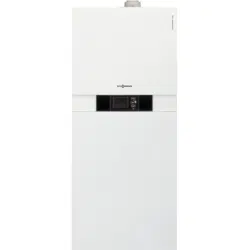
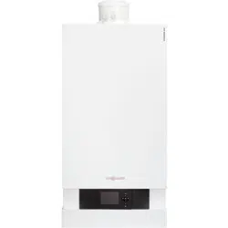
Boiler model 2.5 to 4.0
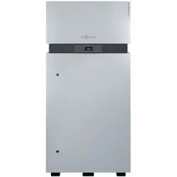
Boiler model 5.0 and 6.0
15
5838 950 - 03
Vitocrossal 300 CA3B Series 2.5 to 6.0 Operating
A screensaver appears if there has not been any operation
for some time:
The programming unit is equipped with a touchscreen.
To make settings and call up information, press the
on-screen buttons.
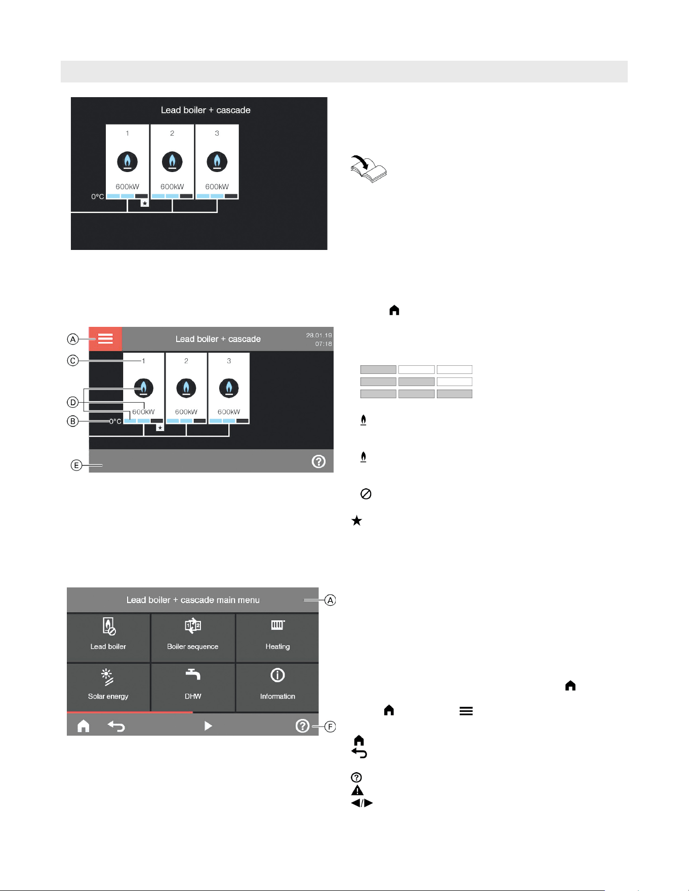
Default display
In the default display, the number of boiler sections in-
stalled in the heating system is shown in a specific
order (boiler section sequence).
Call up the default display as follows:
g If the screensaver is active:
Tap anywhere on the screen.
g You are now in the main menu (refer to the main menu
overview on page 34).
Press .
You can change any settings on your heating system
centrally at the programming unit of the system and lead
control boiler section 1.
If remote control units are installed in your rooms, you
can also adjust the settings at the remote control units.
Remote control operating instructions
System and Lead Control Boiler Section 1 Programming Unit
Operation
Boiler section operating mode
The depiction of the flame represents the current boiler
section heating output:
g 1 to 33%
g 34 to 66%
g 66 to 100%
Circle symbol:
g Blue:
The boiler section has been enabled by the system and
lead control unit and is operational.
g Gray:
The boiler section is available for generating heat but has
not been called for by the system and lead control unit.
g :
The boiler section is unavailable for generating heat.
Denotes the lead boiler
The value below the circle indicates the current output
(in MBH or kW based on the measurement units selected).
Main menu
In the main menu, you can make all settings across the
range of functions available at the system and lead control
unit as well as scan details, such as the heating defaults
and set time programs. Refer to the main menu overview on
page 34.
Call up the main menu as follows:
g If the screensaver is active:
Tap anywhere on the display and then tap .
g From anywhere in the menu:
Tap and then tap .
Footer buttons
Returns you to the home screen.
Takes you to the previous step in the menu or
cancels a setting that has been started.
Calls up the help text.
Calls up fault or service messages.
Scrolling through the menu.
The screensaver appears after a while when no input has
been made.
Legend
A Header
F Footer
Legend
A Header
B Actual common supply temperature (boiler)
C Boiler section number in the sequence
D Details of the boiler section operating status
(see the following chapter)
E Footer
16
5838 950 - 03
Vitocrossal 300 CA3B Series 2.5 to 6.0 Operating
Operation
A screensaver appears after opening the control unit,
or if there has not been any operation for some time:
Each service display unit is equipped with a touchscreen.
To make adjustments and scan information, tap the
on-screen buttons.
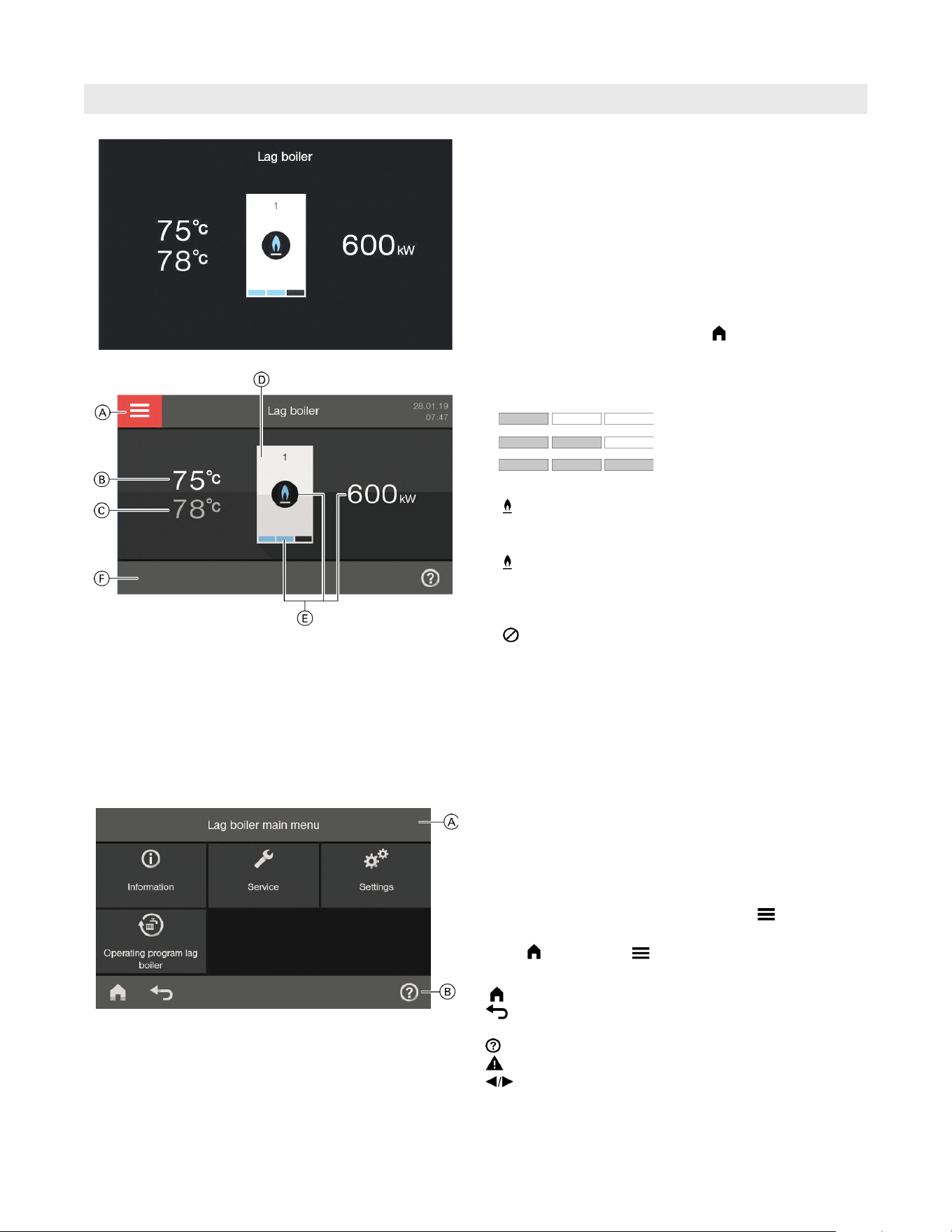
Home screen
Call up the home screen as follows:
H Screensaver is active:
Tap the display anywhere.
H From anywhere in the menu tap .
Boiler section operating mode
The flame symbol indicates the current boiler heating
output:
g 1 to 33%
g 34 to 66%
g 66 to 100%
Circle symbol:
g Blue:
The boiler section has been enabled by the system and
lead control unit and is operating.
g Gray:
The boiler section is available for generating heat but
has not been called for by the system and lead control
unit.
g :
The boiler section is not available for generating heat.
Legend
A Header
B Actual boiler section water temperature
C Set boiler section water temperature
D Boiler section number
E Details on the boiler section operating mode
(see the following chapter)
F Footer
Footer buttons:
Returns you to the home screen.
Takes you back one menu level or cancels
a setting that has been started.
Calls up the help text.
Calls up fault or service messages.
Scrolls through the menu.
Legend
A Header
F Footer
Main menu
You can make scans and settings in the main menu.
Refer to the main menu overview on page 34.
Call up the main menu as follows:
H Screensaver is active:
Tap the display anywhere and then tap .
H From anywhere in the menu:
Tap and then tap .
Service Display Lag Boiler
Sections

17
5838 950 - 03
Vitocrossal 300 CA3B Series 2.5 to 6.0 Operating
Starting the Heating System
Operation
1. Check the heating system pressure at the pressure
gauge. If the pressure of the heating system is too low,
top up the water or notify your heating contractor.
2. Open the gas shut-off valve on every boiler.
3. Switch ON the power supply, e.g. at a separate MCB/
fuse or a mains isolator.
Legend
A ON/OFF switch
B ON indicator (green)
C Fault indicator (red)
Ask your heating contractor about the following:
H Boiler and relevant control unit type
H Level of the required system pressure
H Position of the following components:
– Temperature/pressure gauge
– Gas shut-off valve
– Air vent
Note: The ON/OFF switches of the lag boiler sections
must be switched ON during system commissioning.
18
5838 950 - 03
Vitocrossal 300 CA3B Series 2.5 to 6.0 Operating
Shutting Down the Heating System
IMPORTANT
With frost protection monitoring
For every heating circuit select the “Standby mode”
operating program
H No central heating
H No DHW heating
H Frost protection for the boiler and the DHW tank
is active.
Pump exercise function
Circulation pumps are started for 10 sec. once every 24
hours to prevent the pumps from seizing up. This function
is active during all operating programs and during warm
weather shutdown.
If outdoor temperatures of below 37°F (3°C) are expected,
take appropriate measures to protect the heating system
from frost.
If necessary, contact your heating contractor.
Information on a prolonged shutdown
H Circulation pumps may seize up as they are not being
supplied with power.
H It may be necessary to reset the date and time
(for details refer to page 29).
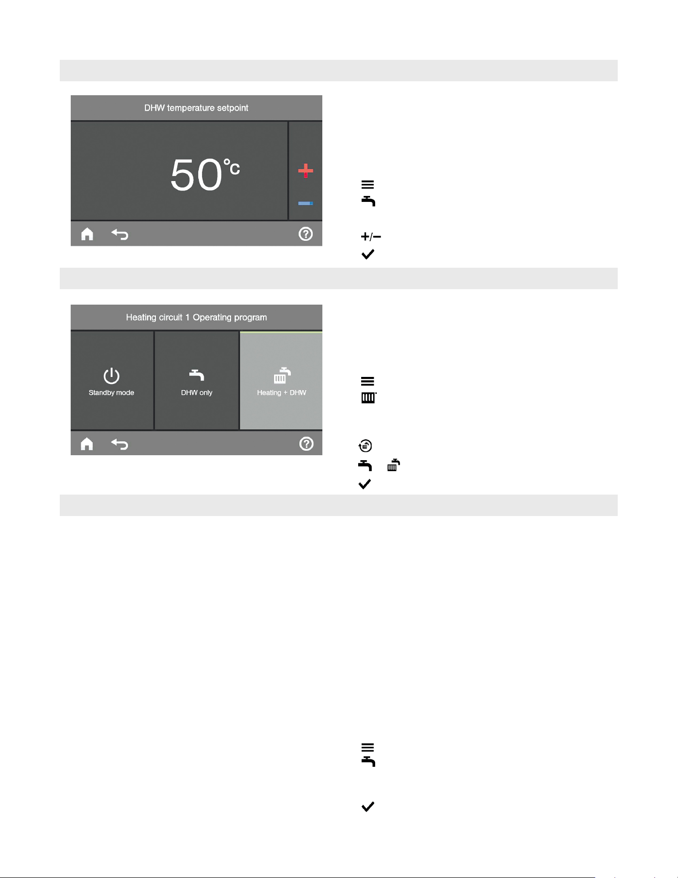
Symbol Operating program Function
“Heating and DHW” H The rooms of the
selected heating
circuit are heated in
accordance with the
room temperature and
time program specified
(see chapter “Central
heating”).
H DHW is heated in
accordance with the
DHW temperature and
time program specified
(see chapter “DHW
heating”).
w
“DHW only” H DHW is heated in
accordance with the
DHW temperature and
time program specified
(see chapter “DHW
heating”).
H No central heating
H Frost protection for
the boiler and the
DHW tank is active.
9
“Standby mode” H No central heating
H No DHW heating
H Frost protection for
the boiler and the DHW
tank is active.
Special operating programs
H “External hook-up”
The operating program set at the system and lead
control unit was changed by an external device,
e.g. EA1 extension.
H “External program”
The operating program set at the control unit was
changed over by the Vitocom communication interface.
H “Holiday program”
(for details refer to page 26).
Note: In the main menu, you can scan the set operating
program under “Information”.
Operating programs for central heating, DHW, frost protection
Without frost protection monitoring (shutdown)
1. Switch OFF the ON/OFF switch on every system and
lead control unit (for details refer to page 17).
2. Close the gas shut-off valves.
3. Isolate the heating system from its main power supply,
e.g. at the separate MCB/fuse or at a mains isolator.
Operating Program
Operation
19
5838 950 - 03
Vitocrossal 300 CA3B Series 2.5 to 6.0 Operating
Time programs are set at the system and lead boiler
section control. The following explains how to input
the settings for a time program. The special features
of individual time programs are allotted to the relevant
chapters.
You can set up a time program for the following functions:
H Central heating
H DHW heating
H DHW recirculation pump
The time program allows you to divide the day into time
blocks. These are called time phases. It is for you to
decide what happens in these time phases, e.g. whether
your rooms should be heated to the standard room tem-
perature.
H You can set the time program individually, to be the
same, or different, for every day of the week.
H You can select up to 4 time phases per day.
H For each time phase you select the start and end points.
H In the main menu, you can scan the time programs
under “Information” (for details refer to page 34).
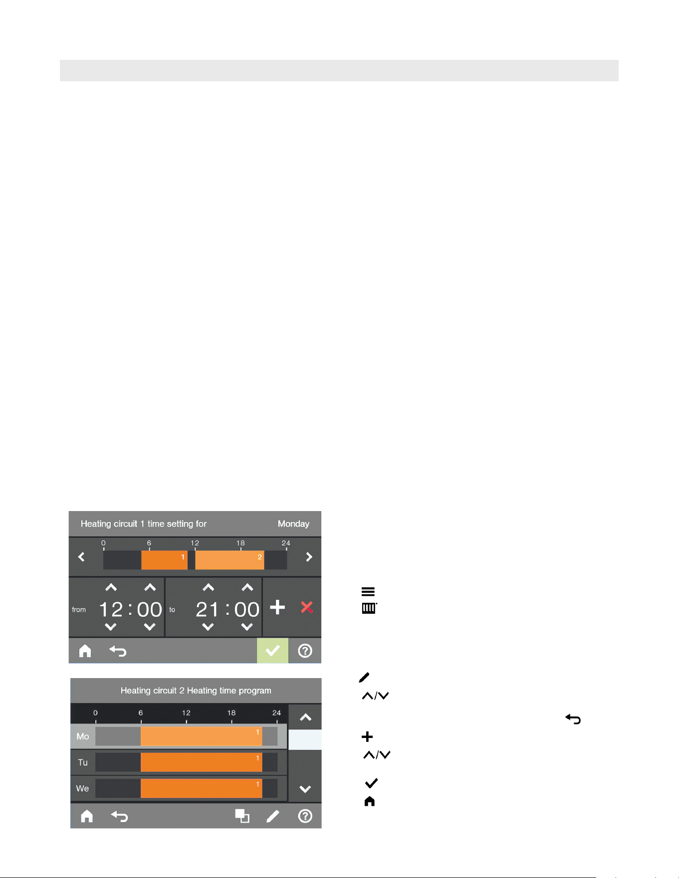
Setting time phases
Example
H Time program for “Monday”
H Time phase 1: 05:30 am to 09:00 am (05:30 h to 09:00 h)
H Time phase 2: 4:30 pm to 10:00 pm (16:30 h to 22:00 h)
In between these time phases the system heats
to a reduced temperature.
From the home screen tap the following buttons:
1.
2.
3. “Heating circuit 1”
4. “Time program heating”
5. “Mo”
6.
7. for the start and end point of time phase 1.
The bar in the time diagram is adjusted.
Cancelling the setting of a time phase early .
8. for time phase 2
9. for the start and end point of time phase 2.
The bar in the time diagram is adjusted.
10. to confirm
11.
Note: The settings described in the following, using room
heating Heating circuit 1 as an example, also apply
to DHW heating and the DHW recirculation pump.
Time Program
Factory set condition
g Time phase 1:
12:00 a.m. to 12:00 a.m. (00:00 h to 24:00 h)
Central Heating
20
5838 950 - 03
Vitocrossal 300 CA3B Series 2.5 to 6.0 Operating
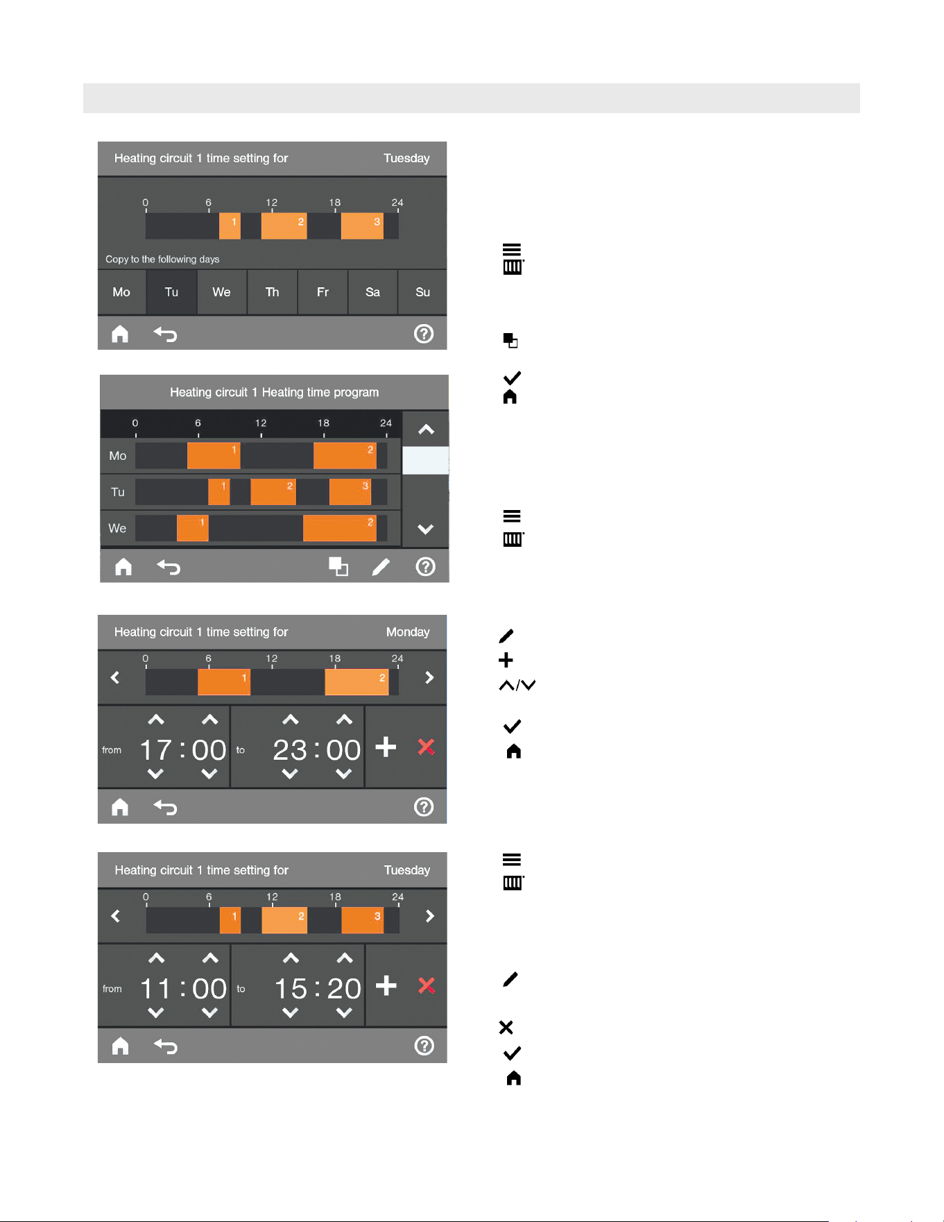
Time Program (continued)
Transferring the time program to other days of the week
You can copy this time program for any other days of
the week.
You want to copy this time program for Monday to the
period Tuesday to Friday.
Tap the following on-screen buttons:
1.
2.
3. Heating circuit 1
4. “Time program heating”
5. “Mo”
6.
7. “Tu” , “We”, “Th”, “Fr”
8. to confirm
9.
Central Heating
Changing time phases
For Tuesday you want to change the start point of time
phase 2 to 2:30 pm (14:30 h).
From the home screen tap the following buttons:
1.
2.
3. “Heating circuit 1”
4. “Time program heating”
5. “Tu”
6.
7. for time phase 2
8. for the start point of time phase 2.
The bar in the time diagram is adjusted.
9. to confirm
10.
Deleting time phases
For Wednesday you want to delete time phase 2.
From the home screen tap the following buttons:
1.
2.
3. “Heating circuit 1”
4. “Time program heating”
5. “We”
6.
7. Select time phase 2
8.
9. to confirm
10.
21
5838 950 - 03
Vitocrossal 300 CA3B Series 2.5 to 6.0 Operating
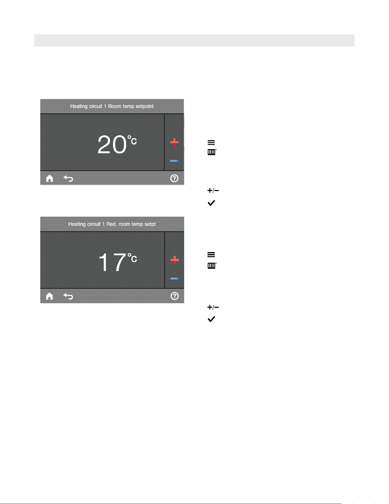
Room Temperature
Note: Further information can be found in chapter
“Terminology” in this manual.
You can make the following settings only at the system
and lead control boiler section 1.
Setting the standard room temperature for the selected
heating circuit
Factory setting: ....................................... 68°F (20°C)
Setting range: ................... 37°F to 99°F (3°C to 37°C)
From the home screen tap the following buttons:
1.
2.
3. “Heating circuit 1”, “Heating circuit 2” or “Heating
circuit 3” as the required heating circuit
4. “ Room temp setpoint”
5. for the required value
6. to confirm
Setting reduced room temperature
Factory setting: 64°F (18°C)
Setting range: 37°F to 99°F (3°C to 37°C)
From the home screen tap the following buttons:
1.
2.
3. “Heating circuit 1”, “Heating circuit 2” or “Heating
circuit 3” as the required heating circuit
4. “Red room temp setpt”
5. for the required value
6. to confirm
Central heating with this temperature:
H Between the time phases for central heating with
standard temperature
H In the holiday program
Central Heating

22
5838 950 - 03
Vitocrossal 300 CA3B Series 2.5 to 6.0 Operating
Operating Program
Central Heating
Note: Further information can be found in chapter
“Terminology” in this manual.
Setting the operating program
You can make the following settings only at the system
and lead control boiler section 1.
From the home screen tap the following buttons:
1.
2.
3. “Heating circuit 1”, “Heating circuit 2” or “Heating
circuit 3” as the required heating circuit
4.
5. Select the operating program, e.g.
6. to confirm
Note: Further information can be found in chapter
“Terminology” in this manual.
You can make the following settings only at the system
and lead control boiler section 1.
Setting a time program
Factory setting: One time phase from 12:00 am and
12:00 am (00:00 to 24:00 h) for every day of the week
From the home screen tap the following buttons:
1.
2.
3. “Heating circuit 1”, “Heating circuit
2” or “Heating circuit 3” as the required heating circuit
4. “Time program heating”
For procedure on setting a time program, refer to page 19.
Note: When adjusting the setting, bear in mind that your
heating system requires some time to heat the
rooms to the required temperature.
Time Program
23
5838 950 - 03
Vitocrossal 300 CA3B Series 2.5 to 6.0 Operating
Heating Curve
Central Heating
Note: Further information can be found in chapter
“Terminology” in this manual.
You can make the following settings only at the system
and lead control boiler section 1.
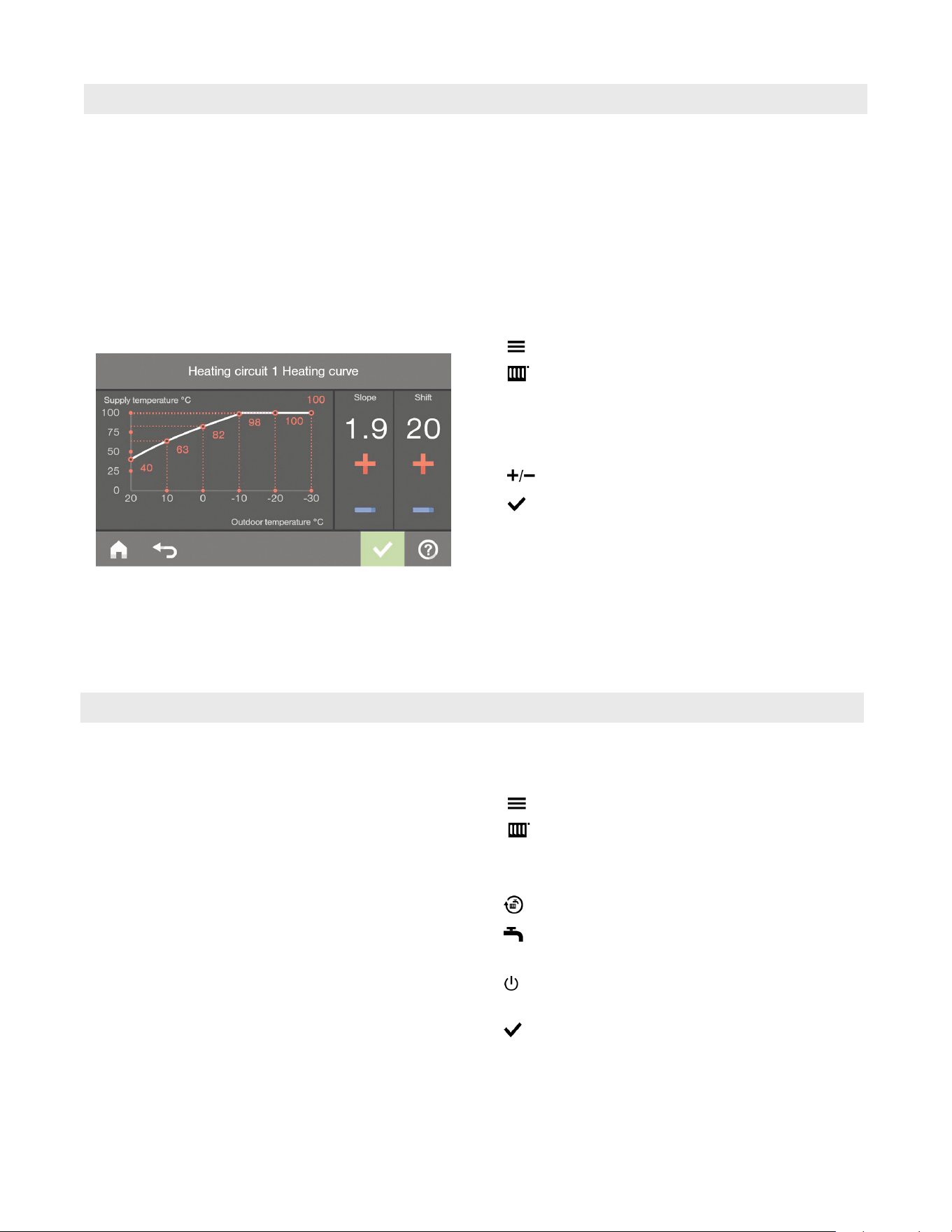
Setting the heating curve
Factory setting:
H “Slope”: 1.4
H “Shift” of the heating curve: 0
From the home screen tap the following buttons:
1.
2.
3. “Heating circuit 1”, “Heating circuit 2” or “Heating
circuit 3” as the required heating circuit
4. “Heating curve”
5. for the required value for “Slope” or “Shift”
6. to confirm
Example: A graph clearly shows the change in the heating
curve as soon as you alter the value for the
slope or shift.
From the home screen tap the following buttons:
1.
2.
3. “Heating circuit 1”, “Heating circuit 2” or “Heating
circuit 3” as the required heating circuit
4.
5. (no central heating)
or...
(frost protection for the boiler
and the DHW tank is enabled)
6. to confirm
Stopping Central Heating
Depending on various outdoor temperatures
(shown on the horizontal axis), the as signed
set supply temperatures for the heating circuit
are displayed along the heating curve in red.
You can make the following settings only at the system
and lead control boiler section 1.
24
5838 950 - 03
Vitocrossal 300 CA3B Series 2.5 to 6.0 Operating
Ending “Comfort mode”
From the home screen tap the following buttons:
1.
2.
3. “Heating circuit 1”, “Heating circuit 2” or “Heating
circuit 3” as the required heating circuit
4. “Comfort mode”
5. “OFF”
6. to confirm
or...
H Automatically when the system switches to standard
heating mode in accordance with the time program
H Automatically after 8 hours
Note: If you want to make changes to this, contact your
local heating contractor.
Comfort Function
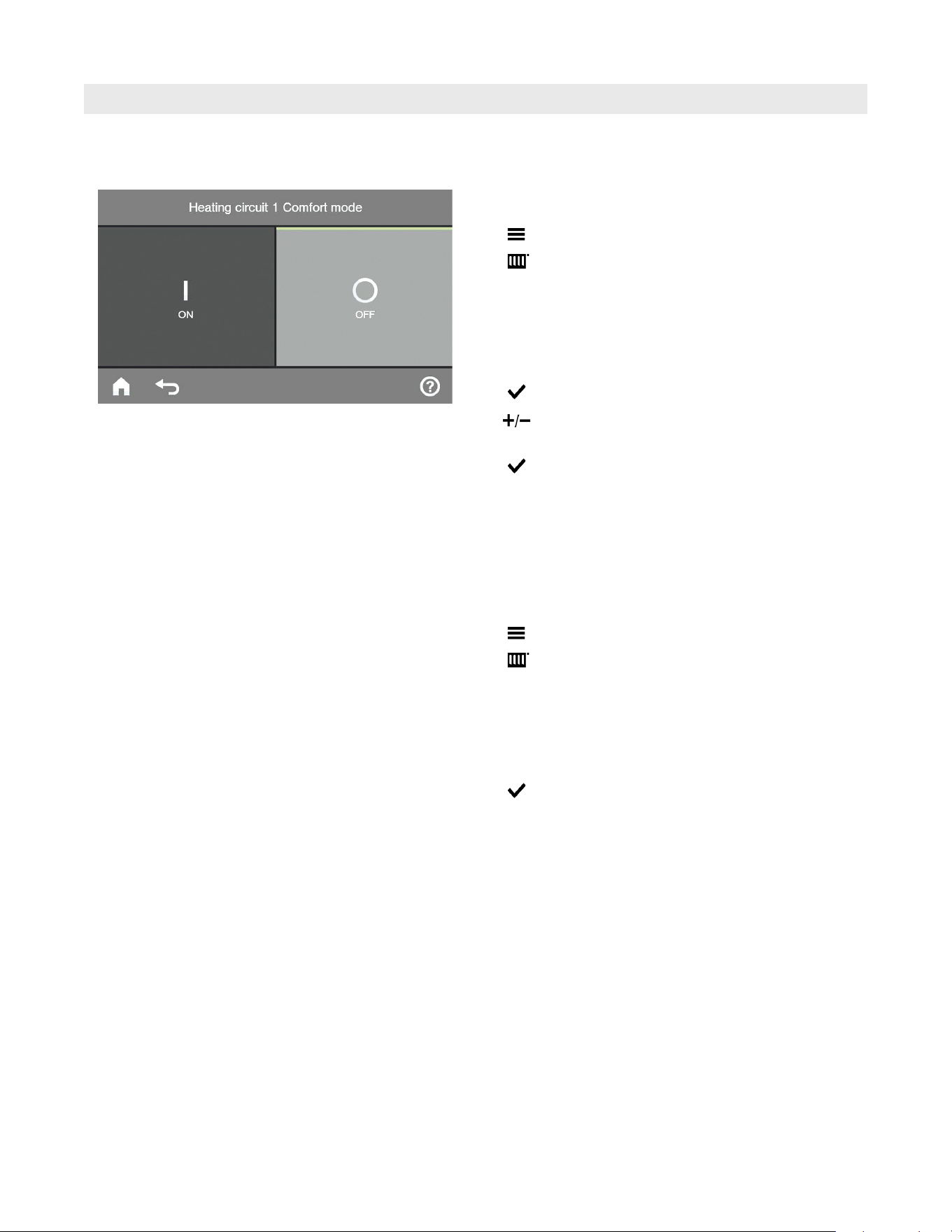
Setting “Comfort mode”
From the home screen tap the following buttons:
1.
2.
3. “Heating circuit 1”, “Heating circuit 2” or “Heating
circuit 3” as the required heating circuit
4. “Comfort mode”
5. “ON”
6. to confirm
7. for the required room temperature target in
comfort mode
8. to confirm
H The rooms are heated to the required temperature.
H Provided your heating contractor has not altered the
settings, DHW is heated to the selected set temperature
first, before central heating begins.
H The DHW recirculation pump is switched on (if installed).
Central Heating
You can make the following settings only at the system
and lead control boiler section 1.
25
5838 950 - 03
Vitocrossal 300 CA3B Series 2.5 to 6.0 Operating
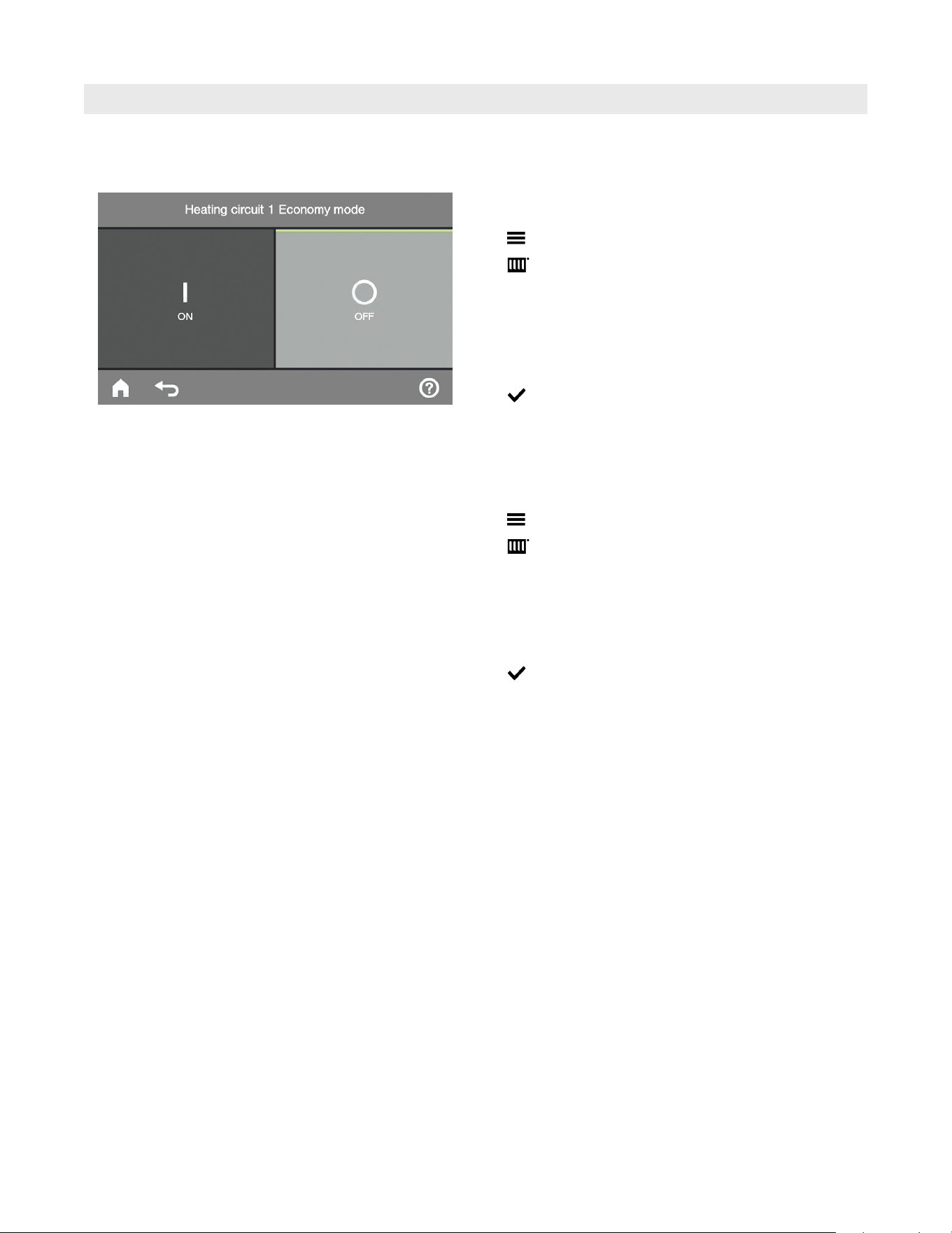
Central Heating
Setting “Economy mode”
From the home screen tap the following buttons:
1.
2.
3. “Heating circuit 1”, “Heating circuit 2” or “Heating
circuit 3” as the required heating circuit
4. “Economy mode”
5. “ON”
6. to confirm
Note: This energy saving function can only be enabled
in standard heating mode.
Ending “Economy mode”
Tap the following on-screen buttons:
1.
2.
3. “Heating circuit 1”, “Heating circuit 2” or “Heating
circuit 3” as the required heating circuit
4. “Economy mode”
5. “OFF”
6. to confirm
or...
Automatically when the system switches to reduced
heating mode in accordance with the time program.
Energy Saving Function “Economy Mode”
You can make the following settings only at the system
and lead control boiler section 1.
26
5838 950 - 03
Vitocrossal 300 CA3B Series 2.5 to 6.0 Operating
Central Heating
Energy Saving Function “Holiday Program”
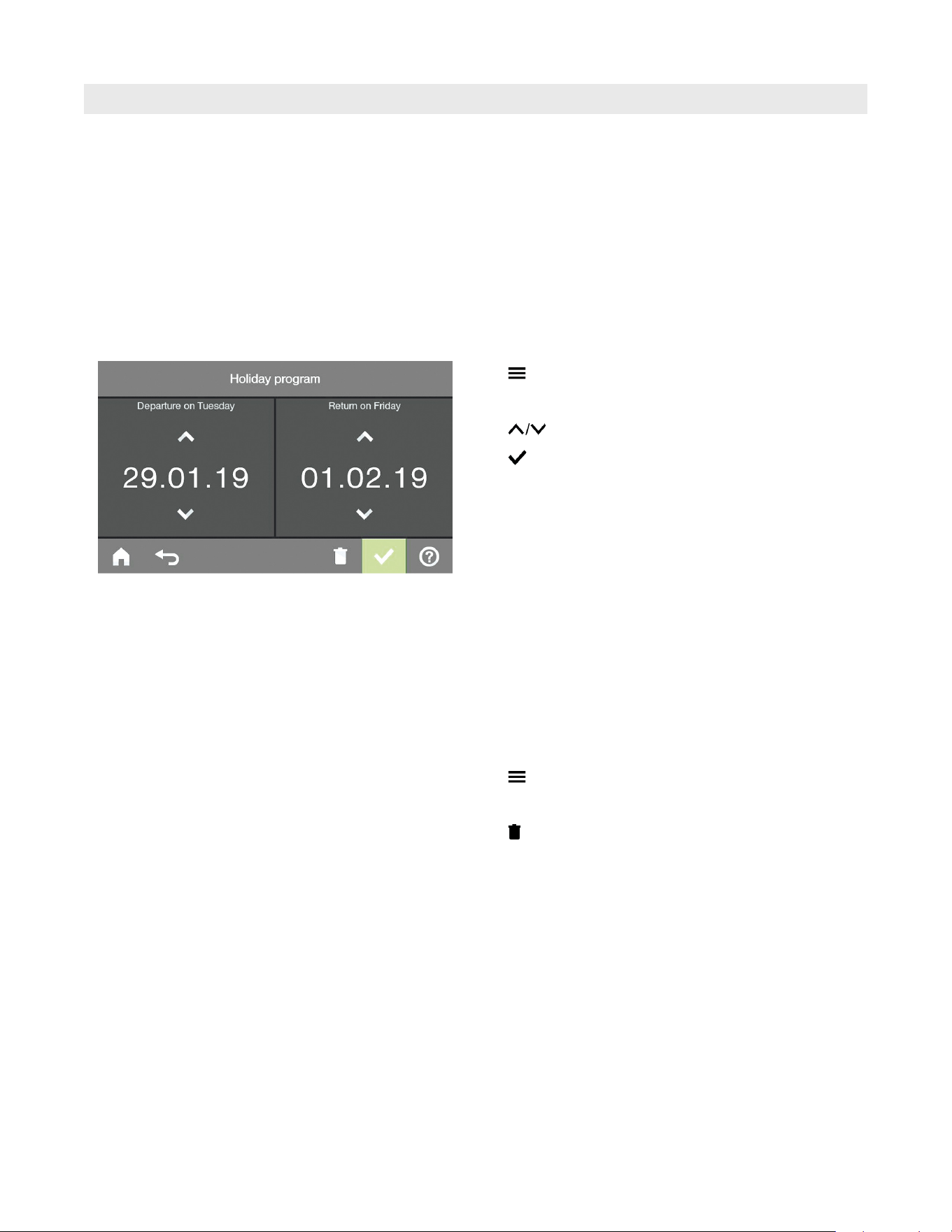
Setting “Holiday program”
Note: The holiday program affects all heating circuits.
If you want to make changes to this, contact your
local heating contractor.
The holiday program starts at 12:00 am (00:00 h) the day
after the departure date. The holiday program ends at
12:00 am (00:00 h) on the return date. This means that
the set time program is active on the days of departure
and return.
From the home screen tap the following buttons:
1.
2. “Holiday program”
3. for “Departure date” and “Return date”
4. to confirm
The holiday program has the following effect:
H Central heating:
– For heating circuits in the operating program
“Heating and DHW”:
The rooms are heated to the set reduced room
temperature (for details refer to page 21).
– For heating circuits in the operating program
“DHW only”:
No central heating with frost protection for the boiler
and the DHW tank is active.
H DHW heating:
No DHW heating. Frost protection for the DHW tank
is active.
Cancelling or deleting the “Holiday program”
From the home screen tap the following buttons:
1.
2. “Holiday program”
3.
You can make the following settings only at the system
and lead control boiler section 1.
27
5838 950 - 03
Vitocrossal 300 CA3B Series 2.5 to 6.0 Operating
DHW Heating
DHW Temperature
Factory setting: ...................................... 122°F (50°C)
Setting range: ............... 50°F to 140°F (10°C to 60°C)
If you want to make changes to this, contact your local
heating contractor.
From the home screen tap the following buttons:
1.
2.
3. “DHW temperature setpoint”
4. for the required value
5. to confirm
Further information can be found in chapter “Terminology”
Setting the operating program
From the home screen tap the following buttons:
1.
2.
3. “Heating circuit 1”, “Heating circuit 2” or “Heating
circuit 3” as the required heating circuit
4.
5. or
6. to confirm
Operating Program
Time Program
Further information can be found in chapter “Terminology”
Setting the time program
Factory setting: “Automatic”
During operation with standard room temperature, DHW
in the DHW tank is heated to the set DHW temperature.
The time phase for DHW heating automatically starts
half an hour earlier than the time phase for central
heating with standard room temperature. DHW heating
will start, for example, at 5:30 a.m. if the start time for
central heating is 6:00 a.m. This means hot water is
already available when your system starts operating
with standard room temperature.
You can change this time program individually in
accordance with your requirements.
From the home screen tap the following buttons:
1.
2.
3. “Time program DHW”
4. “Individual”
5. to confirm
For setting a time program, refer to page 19.
You can make the following settings only at the system
and lead control boiler section 1.
You can make the following settings only at the system
and lead control boiler section 1.
You can make the following settings only at the system
and lead control boiler section 1.

28
5838 950 - 03
Vitocrossal 300 CA3B Series 2.5 to 6.0 Operating
Time Program (continued)
DHW Heating
Note:
g DHW is not heated between the time phases. Frost
protection for the DHW tank is enabled.
g When setting time programs, bear in mind that your
heating system requires some time to heat the DHW
tank to the required temperature.
g Any DHW heating process that has started will continue
until the set DHW temperature is reached, even if the
stop time has been reached.
DHW 4th phase heating (auxiliary function)
This function can be used to heat the water in the DHW
tank to a higher set DHW temperature. Your heating
contractor can enable this function by specifying a
second set DHW temperature.
Set time phase 4 for this. During this time, DHW will
be heated to the second set DHW temperature value.
Note: A start and stop time must be set for the 2nd and
3rd time phase.
DHW heating once, outside the time program
Note: The operating program “Heating and DHW” or
“DHW only” must be set for at least one system
heating circuit. Enable and then immediately disable
“Comfort mode” (for details refer to page 24).
This avoids unintentional central heating with the
standard room temperature.
Setting the time program for the DHW recirculation pump
Factory setting: “Automatic”
The DHW recirculation pump operates in parallel to the
DHW heating time program.
You can change this time program individually in
accordance with your requirements.
From the home screen tap the following buttons:
1.
2.
3. “Time program DHW recirculation”
4. “Individual”
5. to confirm
For setting a time program, refer to page 19.
Note: Between the time phases, the DHW recirculation
pump remains off.
Switching off DHW heating
From the home screen tap the following buttons:
1.
2.
3. “DHW temperature setpoint”
4. Use to adjust to 50°F (10°C)
5. to confirm
29
5838 950 - 03
Vitocrossal 300 CA3B Series 2.5 to 6.0 Operating
Setting the Display Backlighting
From the home screen tap the following buttons:
1.
2. “Settings”
3. “Screen”
4. “Brightness screen saver” or “Brightness control”
5. for the required value
6. to confirm
Further Adjustments
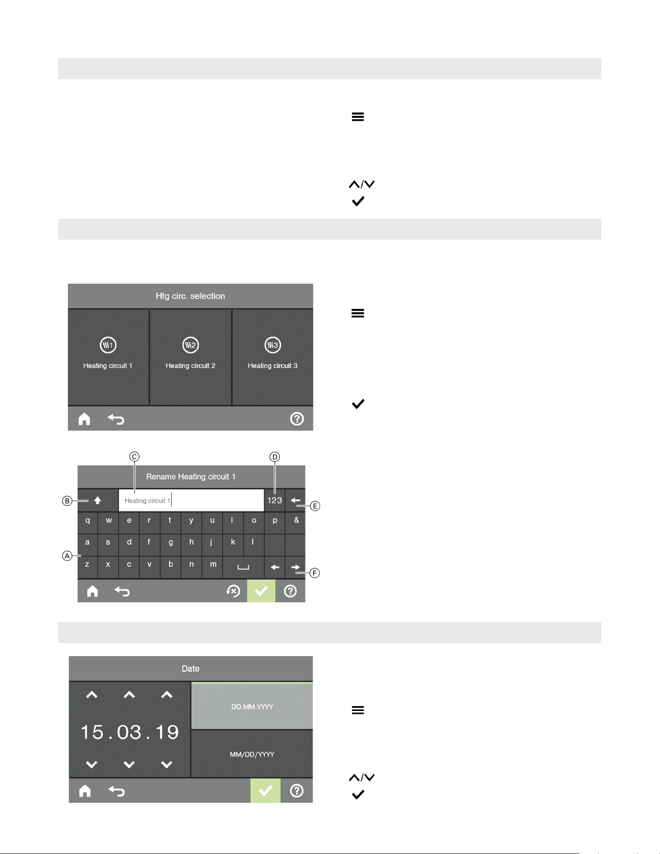
Naming Heating Circuits
You can name all heating circuits individually.
From the home screen tap the following buttons:
1.
2. “Settings”
3. “Name for heating circuit”
4. Select “Heating circuit 1”, “Heating circuit 2” or
“Heating circuit 3” and enter the required name,
such as “Ground floor”.
5. to confirm
The name assigned for each heating circuit appears
in the main menu.
Legend
A Keypad
B Shift between upper and lower case letters
C Text box
D Shift to the number keypad
E Delete individual characters
F Scroll forwards and backwards in the text box
Setting the Time and Date
The time and date are factory-set. If your heating system
has been shut down for a prolonged period, you may need
to reset the time and date.
From the home screen tap the following buttons:
1.
2. “Settings”
3. “Date and Time”
4. “Date” or “Time”
5. for the required value
6. to confirm
You can make the following settings only at the system
and lead control boiler section 1.
30
5838 950 - 03
Vitocrossal 300 CA3B Series 2.5 to 6.0 Operating
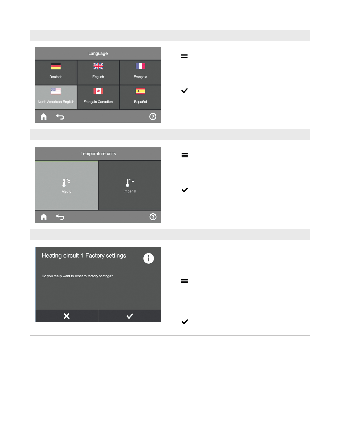
Further Adjustments
Language Selection
From the home screen tap the following buttons:
1.
2. “Settings”
3. “Language”
4. Required language
5. to confirm
Setting the Temperature Units
From the home screen tap the following buttons:
1.
2. “Settings”
3. “Temperature units”
4. “Metric” or “Imperial”
5. to confirm
Restoring Factory Settings
You can individually restore all modified values for each
heating circuit to their factory setting.
From the home screen tap the following buttons:
1.
2. “Settings”
3. “Factory settings”
4. “Heating circuit 1”, “Heating circuit 2” or “Heating
circuit 3” as the required heating circuit
5. to confirm
System setting Settings and values that are reset
“Heating circuit 1”, “Heating circuit 2” or “Heating circuit 3” H Room temperature target
H Reduced room temperature target
H Operating program
H DHW temperature target
H Time program for central heating
H Time program for DHW heating
H Time program for DHW recirculation pump
H Heating curve slope and shift
H Comfort and energy saving functions are deleted.
Note: If heating circuits have been designated, the
assigned names remain intact.
See “Naming Heating Circuits” on page 29.
Note: This must be performed on the main user interface
as well as all service displays.
You can make the following settings only at the system
and lead control boiler section 1.
31
5838 950 - 03
Vitocrossal 300 CA3B Series 2.5 to 6.0 Operating
Scanning Information
Scanning
Subject to the components connected and the settings
made, you can scan current temperatures and operating
conditions.
Information in the main menu is split into groups:
H “General”
H “Combustion controller”
H “Heating circuit 1”
H “Heating circuit 2”
H “Heating circuit 3”
H “DHW”
H “Solar energy”
H “Reset data”
H “Opening source licenses”
H “Service contact”
Note: The assigned name will appear if heating circuits
have been designated.
See chapter “Naming heating circuits”.
Detailed options for calling up data on individual groups
From the home screen tap the following buttons:
1.
2. “Information”
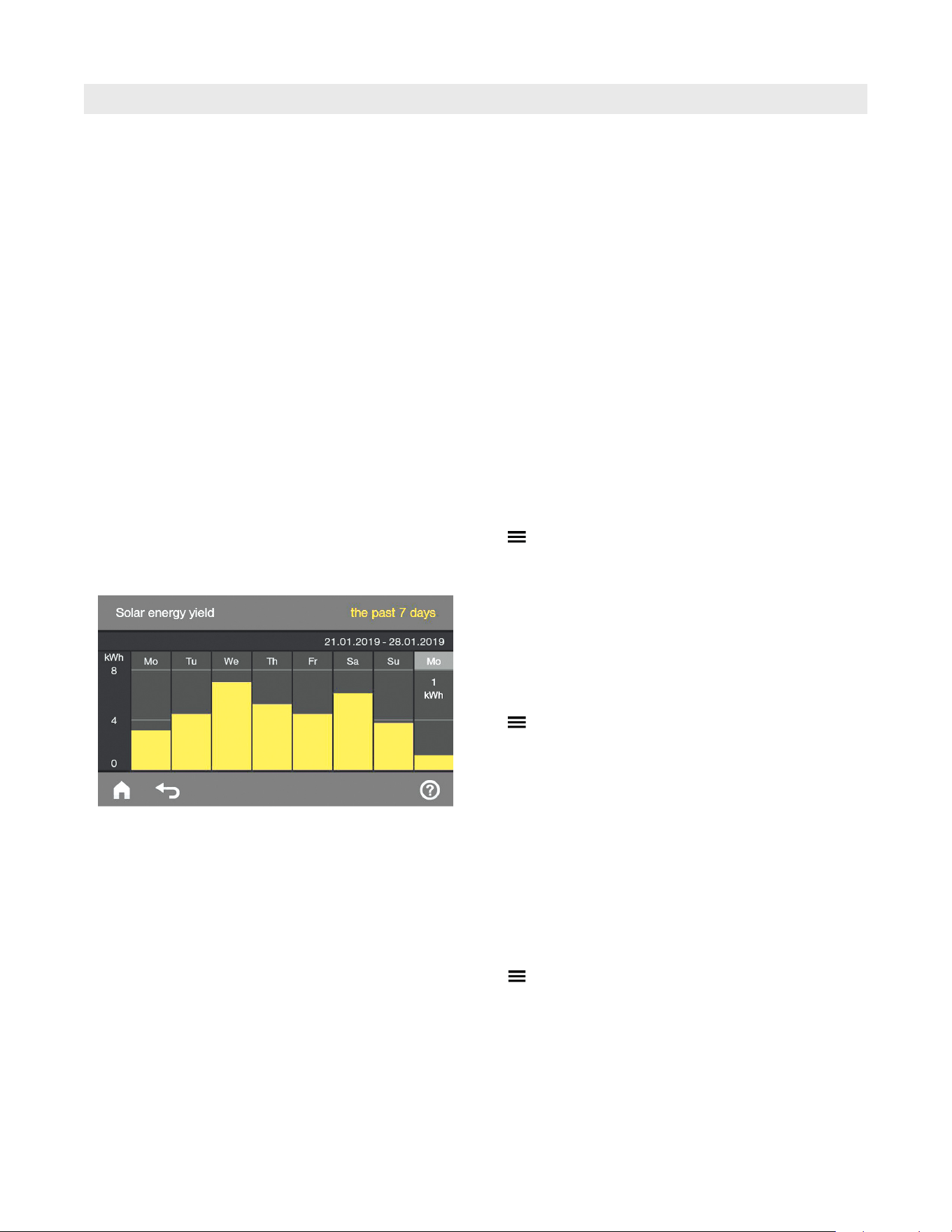
Scanning the solar energy yield in conjunction with solar
thermal systems
Only in connection with solar control unit, type SM1.
There you can scan the solar energy yield in conjunction
with a Vitosolic solar control unit.
From the home screen tap the following buttons:
1.
2. “Solar energy”
Tap on the respective day of the week if the figure is to
be displayed as a numerical value.
Note: For further scanning options, e.g. for the solar
circuit pump hours run, see the extended menu
under “Information” in the “Solar” group.
Service address
If your heating contractor has entered their details, you
can scan these.
From the home screen tap the following buttons:
1.
2. “Information”
3. “Service contact”
Note: If there are no details, tap the gray field. This will
display the keypad; see keypad diagram on page 29.
You can enter contact details.
The solar energy yield is shown in diagrammatic form.
32
5838 950 - 03
Vitocrossal 300 CA3B Series 2.5 to 6.0 Operating
Scanning Information (continued)
Scanning
Resetting data
You can reset the following data:
H Burner hours run
H Fuel consumption
H In conjunction with a solar thermal system:
Solar energy yield, solar circuit pump hours run
and hours run output 22
H All the above data simultaneously
From the home screen tap the following buttons:
1.
2. “Information”
3. “Reset data”
4. Select required data point or “All data”.
5. to confirm
Tap “Confirm”.
The footer shows
.
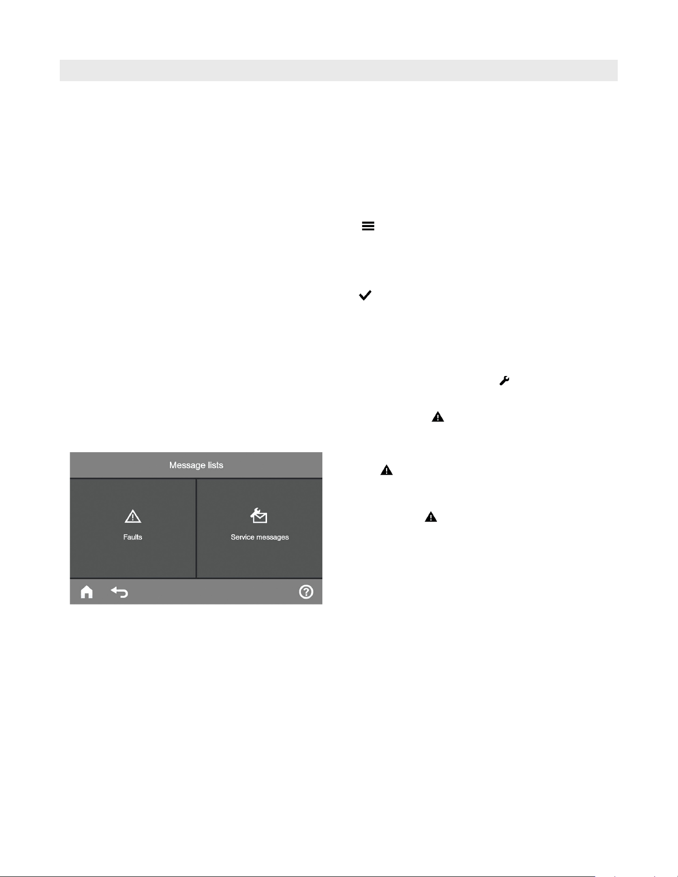
Calling up a service message
1. Tap
in the footer.
The service message will be listed in yellow.
2. Notify your local heating contractor.
After tapping
the following will be displayed if
your heating system has several fault messages
simultaneously:
Tap “Service messages”
The service message will be listed in yellow.
Note: If the service cannot be carried out until a later
date, the service message will be displayed again
the following Monday.
Scanning service messages
Your heating contractor can set service intervals (limits)
(for burner hours run, for example). A service message
is generated when this value is exceeded.
Your display indicates that your heating system is due
for a service by showing symbol and “Service”.
33
5838 950 - 03
Vitocrossal 300 CA3B Series 2.5 to 6.0 Operating
Scanning Information (continued)
Scanning
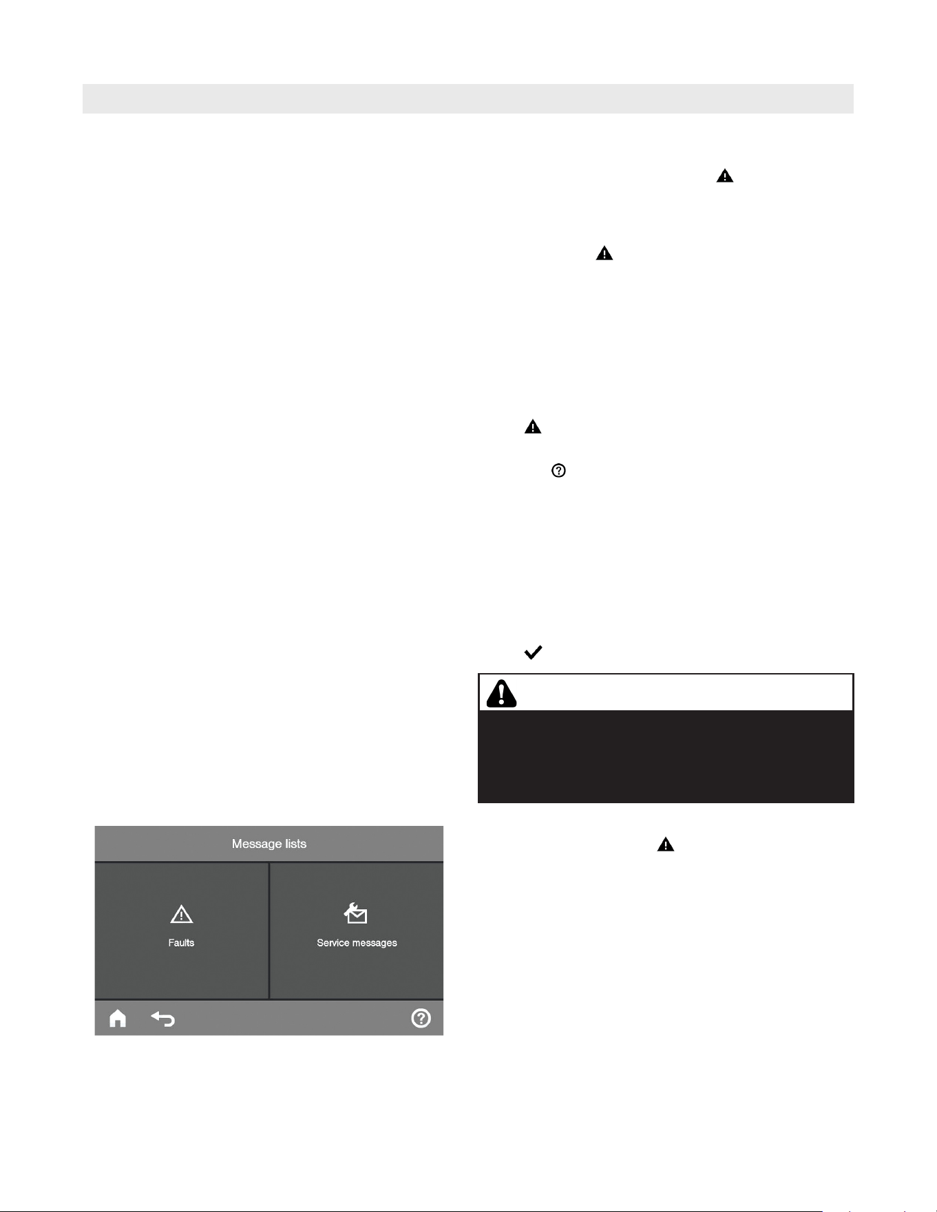
Scanning fault messages
Your display indicates that your heating system has
developed faults by showing symbol
and “Faults”.
The red fault indicator flashes on the control unit
enclosure (see chapter “Starting the heating system”).
Tap “Close”.
The footer shows
.
Note: - If you have connected signalling equipment to
indicate fault messages (e.g. a buzzer),
this is deactivated when the fault message is
acknowledged.
- If troubleshooting cannot be carried out until a
later date, the fault message will be displayed
again the following day at 07:00 am (07:00 h).
The alarm equipment is switched on again.
1. Tap
in the footer. The fault message appears in red
in a list.
2. Tapping calls up information on the heating system
characteristics. Tips on measures you can take yourself
before notifying your heating contractor are displayed.
3. Make a note of the fault code and the cause for the
fault. In this example: f0 “Combustion controller”.
This enables the heating contractor to be better
prepared and may save you unnecessary travelling
costs.
4. Notify your local heating contractor.
5. Tap .
If simultaneously service messages are ‘live’ on your
heating system, tapping on
will show the following
display:
Tap “Faults”
The fault messages will be listed in red.
WARNING
If faults are not rectified, they can have life threatening
consequences. Do not acknowledge fault messages
several times in quick succession. Notify your heating
contractor if a fault recurs. Your heating contractor will
be able to analyze the cause and rectify the fault.
34
5838 950 - 03
Vitocrossal 300 CA3B Series 2.5 to 6.0 Operating
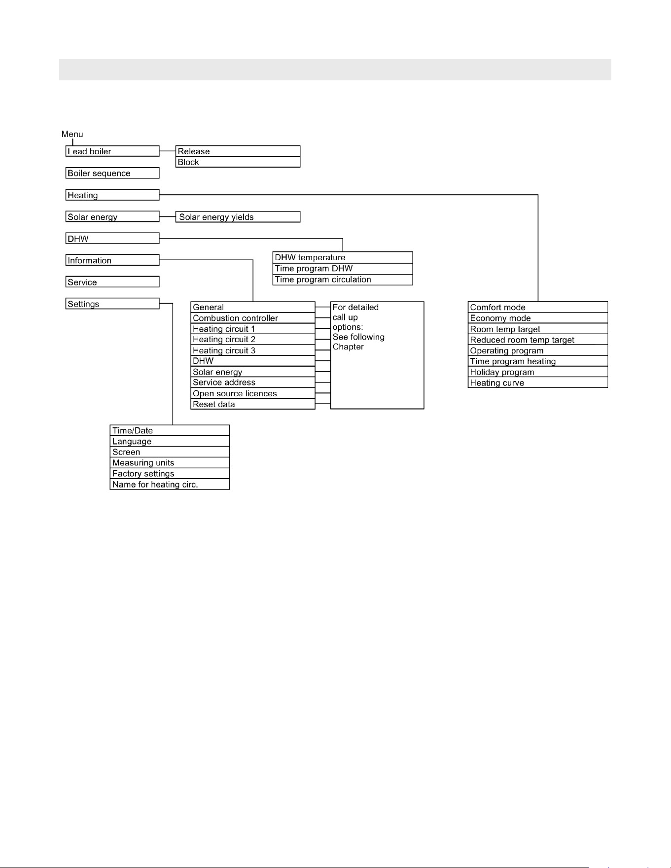
Scanning Options
Lead control unit
Main Menu Overview
35
5838 950 - 03
Vitocrossal 300 CA3B Series 2.5 to 6.0 Operating
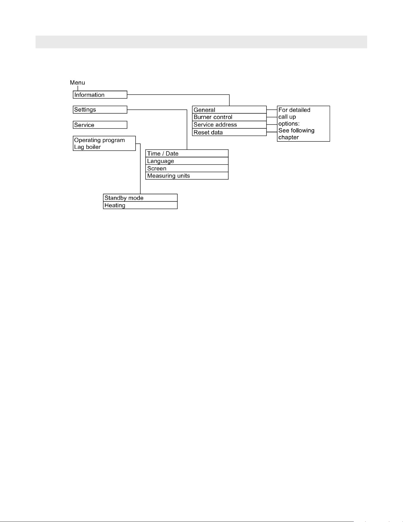
Scanning Options
Main Menu Overview (continued)
Service control display boiler section 2 or 3
36
5838 950 - 03
Vitocrossal 300 CA3B Series 2.5 to 6.0 Operating
Note: Subject to the actual heating system equipment
level, not all of the scans listed here may be
available.
You can scan more details on information marked
with .
General
“Outdoor temp”
“Boiler temperature”
“Flue gas temperature”
“Burner starts”
“Burner hours”
“Boiler sequence”
“Boiler temperature” “Boiler ...”
“Sensor 17A”
“Sensor 17B”
“Common supply temp”/”Common demand temp.”
“Sensor 9”
“Output 20”
“Output 29”
“Output 52”
“Feed pump”
“Central fault mess”
“Participant no.”
"Integral"
“Input ext. EA1”
“Ext. hook-up 0...10V”
“Time”
“Date”
Burner control
"Burner hours run"
"Burner starts"
"Max operational output"
"Gas type"
"Altitude"
"Max boiler temperature"
"Integral threshold controller"
"Runtime optimization"
Heating circuit 1, 2, 3
“Heating program”
- "Slab curing"
- "External hook-up"
- "Holiday program"
- "External program"
- "Comfort mode"
- "Economy mode"
- "Heating and DHW"
- "DHW only"
- "Standby mode"
“Operating status:”
- “Standard heating mode”
- “Reduced mode”
- “Standby mode”
“Time program”
“Room temperature”
“Room temp target”
“Reduced room temp target”
“Set ext. room temp”
“Comfort temp target”
“Slope”
“Shift”
“Heating circ pump”
"Mixing valve"
"Supply temperature / Supply temperature"
“Holiday program”
Solar
“Solar energy history”
“Collector temp”
“Solar DHW”
“Solar circuit pump” (hours run)
“Solar energy”
“Solar circuit pump” (ON/OFF)
or...
“Solar pump circ speed”
“Heating suppr. DHW”
“SM1 output 22” (ON/OFF)
“SM1 output 22” (hours run)
“Sensor 7”
“Sensor 10”
“Heat suppr. heating”
DHW
“DHW time prog”
“DHW circ time prog”
“DHW temperature”
or...
In conjunction with 2 DHW tank temperature sensors:
“DHW temp top”
“DHW temp bottom”
“DHW circ pump”
“Tank primary pump”
Scanning Options under “Information”
Scanning Options
37
5838 950 - 03
Vitocrossal 300 CA3B Series 2.5 to 6.0 Operating
Emissions Test Mode
Emissions
Emissions test mode for testing the flue gas with briefly
raised boiler water temperature. Emissions test mode
should only be activated by your heating contractor during
the annual inspection.
Set the emissions test switch to position .
The following functions are activated:
H The burner is switched ON.
H The pumps are started.
H The mixing valves remain set to the control function.
H The electronic temperature controller regulates the
boiler water temperature.
Ending emissions test mode
1. Set the emissions test switch to position .
Legend
A Emissions test switch (boiler section 1)
B Emissions test switch (boiler section 2)
C Emissions test switch (boiler section 3)
Legend
A Emissions test switch (boiler section 1)
B Emissions test switch (boiler section 2)
Boiler model 2.5 to 4.0
Boiler model 5.0 and 6.0
38
5838 950 - 03
Vitocrossal 300 CA3B Series 2.5 to 6.0 Operating
Troubleshooting
Cause Remedy
The heating system is off H Switch ON the ON/OFF switch on the control units
(refer to page 19).
H Switch ON the mains isolator, if installed (outside the
boiler room).
H Set the MCB in the power distribution board (main
domestic MCB).
H Control unit incorrectly adjusted.
H The remote control (if installed) is set incorrectly.
Central heating must be enabled.
Check the settings and correct if required:
H Operating program (refer to page 22)
H Room temperature (refer to page 21)
H Setting time and date (refer to page 29)
H Time program, central heating (refer to page 22)
H Heating curve (refer to page 23)
Only when operating with DHW heating:
The DHW tank is being heated.
Wait until the DHW tank has been heated up.
Reduce the DHW draw-off rate or temporarily reduce
the standard DHW temperature as required
No fuel. With NG/LPG:
Check the fuel reserves and re-order if required.
With natural gas:
Open the gas shut-off valve. If necessary, check with your
gas supply utility.
“Burner fault” will be displayed. Follow the display prompts.
Reset the burner only once.
is displayed. The red fault indicator
flashes on the control unit enclosure.
Check what type of fault it is. Acknowledge the fault (refer
to page 33). Notify your heating contractor if necessary.
The mixing valve motor is faulty. Adjust the mixing valve manually.
Emissions test switch is set to (refer to page 37).
Set the emissions test switch to position .
WARNING
If faults are not rectified, they can have life threatening
consequences. Do not acknowledge fault messages
several times in quick succession. Notify your heating
contractor if a fault recurs. Your heating contractor will
be able to analyze the cause and rectify the fault.
Separate operating instructions
Rooms are Too Cold
39
5838 950 - 03
Vitocrossal 300 CA3B Series 2.5 to 6.0 Operating
Troubleshooting
Cause Remedy
H Control unit incorrectly adjusted.
H The remote control (if installed) is set incorrectly.
Check the settings and correct if required:
H Operating program (refer to page 22)
H Room temperature (refer to page 21)
H Setting time and date (refer to page 29)
H Time program, central heating (refer to page 22)
H Heating curve (refer to page 23)
is displayed. The red fault indicator flashes on the
control unit enclosure.
Check what type of fault it is. Acknowledge the fault (refer
to page 33). Notify your heating contractor if necessary.
The mixing valve motor is faulty. Adjust the mixing valve manually.
Emissions test switch is set to (see page 37).
Set the emissions test switch to position .
There is No DHW
Cause Remedy
The heating system is off. H Switch ON the ON/OFF switch on the control units
(refer to page 17).
H Switch ON the mains isolator, if installed
(outside the boiler room).
H Set the MCB in the power distribution board
(main domestic MCB).
H Control unit incorrectly adjusted.
H The remote control (if installed) is set incorrectly.
DHW heating must be enabled.
Check the settings and correct if required:
H Operating program (refer to page 27)
H DHW temperature (refer to page 27)
H Time program DHW heating (refer to page 27)
H Setting time and date (refer to page 29)
No fuel. With NG/LPG:
Check the fuel reserves and re-order if required.
With natural gas:
Open the gas shut-off valve.
If necessary, check with your gas supply utility.
is displayed. The red fault indicator flashes on the
control unit enclosure.
Check what type of fault it is. Acknowledge the fault
(refer to page 33).
Notify your heating contractor if necessary.
Rooms are Too Hot
Separate operating instructions
Separate operating instructions
40
5838 950 - 03
Vitocrossal 300 CA3B Series 2.5 to 6.0 Operating
Cause Remedy
The control unit is set incorrectly. Check and correct the DHW temperature, if required
(refer to page 27).
The DHW is being heated by the solar thermal system. Check the settings at the solar control unit and correct
them if required.
Emissions test switch is set to . (see page 37)
Set the emissions test switch to position .
Troubleshooting
Cause Remedy
Heating system fault. Proceed as described on page 33.
Cause Remedy
The time for a service, as specified by your heating
contractor, has arrived.
Proceed as described on page 32.
“Fault” will be Displayed
“Service” will be Displayed
The DHW is Too Hot
Separate operating instructions

41
5838 950 - 03
Vitocrossal 300 CA3B Series 2.5 to 6.0 Operating
Cleaning
All equipment can be cleaned with a commercially
available domestic cleaning agent (non-scouring).
Clean the surface of the programming unit with the
microfibre cloth provided.
Inspection and maintenance
Regular maintenance ensures trouble free, energy
efficient, environmentally responsible and safe heating.
Your heating system must be serviced by an authorized
contractor at least every 2 years. For this, it is best to
arrange an inspection and maintenance contract with
your local heating contractor.
Appliance (boiler)
Increased contamination raises the flue gas temperature
and thereby increases energy losses. We recommend the
appliance is cleaned annually.
DHW tank (if installed)
Maintenance and cleaning should be carried out no
later than 2 years after commissioning and as required
thereafter.
Only a qualified heating contractor should clean the
inside of a DHW tank and the DHW connections.
If any water treatment equipment (e.g. a sluice or
injection system) is installed in the cold water supply
of the DHW tank, ensure this is refilled in good time.
In this connection, observe the manufacturer’s
instructions.
Safety valve (DHW tank)
The function of the safety valve must be checked every
six months by the user or a contractor through venting
(see valve manufacturer’s instructions). The valve seat
may become contaminated.
Water may drip from the safety valve during a heat-up
process. The outlet is open to the atmosphere and must
not be closed off.
Potable water filter (if installed)
To maintain high hygienic standards, proceed as follows:
H Replace filter element on non-back flushing filters every
six months (visual inspection every two months).
H On back flushing filters, back flush every two months.
Damaged cables / lines
If there is damage to the connecting cables or lines of the
appliance or externally installed accessories, these must
be replaced with special cables or lines.
Only use Viessmann cables / lines as replacement.
For this, notify your qualified contractor.
Maintenance
Inspection and Maintenance
Service Schedule
Regular service work ensures reliable, energy-efficient,
and environmentally friendly operation.
The service schedule can be found in the installation and
service instructions.
IMPORTANT
IMPORTANT
Keep boiler and boiler room clear and free from combustible
materials, gasoline and other flammable vapors and liquids.
Do not obstruct the flow of combustion and ventilation air.
All inspection, maintenance, and service must be performed
by a qualified heating contractor.
The boiler should be cleaned at least once a year by a
qualified heating contractor or service agency.

42
5838 950 - 03
Vitocrossal 300 CA3B Series 2.5 to 6.0 Operating
Maintenance
Additional Maintenance Information
Danger of freezing
If the system is subject to freezing temperatures and is not
filled with antifreeze for protection, the system including
the boiler must be drained of water. The valve before
automatic feed valve (if installed) must be closed. All other
valves, air vents and drain valves must remain open.
Long periods of shut-down
In case the heating boiler is shut down for an extended
period of time, i.e. after the heating season, the combustion
chamber, the flue gas collector and the vent pipe should
be properly cleaned to avoid corrosion. The heating
system can stay filled and under pressure. The remaining
condensate should be removed from the flue gas collector
by means of the inspection opening.
Water quality
The lifetime of the entire heating system is influenced by
the water quality. A water treatment system will protect
against damages caused by corrosion and lime formation.
Hard water conditions (i.e. calcium carbonate) must be
avoided as it will cause deposits to accumulate on the
heat exchanger surfaces.
If in any doubt about the water quality, please have a
proper water analysis done. Check with regional chemical
suppliers for boiler water treatment or with Viessmann
Manufacturing Company Inc. directly.
Setback mode (reduced heating mode)
See “Reduced heating mode”.
Operating program
You define the following with the operating program:
H Central heating and DHW heating
or...
H Only DHW, no central heating
or...
H Only frost protection for the boiler and the DHW tank
is active. No central heating, no DHW heating
Note: No operating program is available for central
heating without DHW heating. When you want
central heating, hot water is generally also required
(winter mode).
Operating status
In the operating program “Heating and DHW”, the
operating status changes from “Standard heating mode”
to “Reduced heating mode” and vice versa. The times at
which the operating status is changed over are defined
by you when setting the time program.
Extension kit for heating circuit with mixing valve
Assembly (accessory) for controlling a heating circuit
with mixing valve. See “Mixing valve”.
Heating mode
Standard heating mode
For periods when you will be at home during the day,
heat your rooms to the standard room temperature.
Set the periods (time phases) using the time program
for central heating.
Open source licenses
The programming unit firmware contains open source
software components. Such software is released under
an open source licence and thus available to everyone.
The full text of the licence can be displayed using the
identically named menu point.
Reduced heating mode
For periods when you will be absent or during the night,
heat your rooms to the reduced room temperature.
Set the periods using the time program for central
heating. With underfloor heating systems, reduced heating
mode only yields limited energy savings (see “Underfloor
heating system”).
Room temperature-dependent heating mode
In room temperature-dependent mode, the supply
temperature is controlled according to the room
temperature.
More heat is made available at a lower room temperature
than at a higher one. The room temperature is captured
and transmitted to the control unit by a sensor.
The sensor is fitted in the room. The supply temperature
is regulated independently of the outdoor temperature.
Weather-compensated heating mode
In weather-compensated mode, the supply temperature
is controlled according to the outdoor temperature.
More heat is made available at a lower outdoor
temperature than at a higher one. The outdoor
temperature is captured and transmitted to the control
unit by a sensor.
The sensor is fitted to the exterior of the building.
Underfloor heating
Underfloor heating systems are slow, low temperature
heating systems and only respond very slowly to short
term temperature changes.
Therefore, heating to the reduced room temperature at
night and enabling “Economy mode” during short
absences do not result in significant energy savings.
Terminology
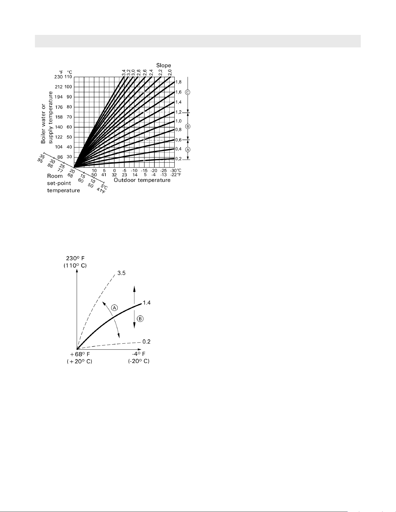
43
5838 950 - 03
Vitocrossal 300 CA3B Series 2.5 to 6.0 Operating
Additional Information
Heating curve
Heating curves illustrate the relationship between the
outdoor temperature, the set room temperature and the
boiler water temperature or supply temperature.
The lower the outdoor temperature, the higher the boiler
water temperature or supply temperature.
In order to guarantee sufficient heat and minimum fuel
consumption at any outdoor temperature, the conditions
of your building and your heating system must be taken
into consideration. The heating curve is set by your
heating contractor for this purpose.
The illustrated heating curves apply with the following
settings:
H Heating curve shift = 0
H Standard room temperature (set value) = 68°F (20°C)
Legend
A Changing the slope:
The gradient of the heating curves changes.
B Changing the shift:
The heating curves are shifted in parallel in a vertical
direction.
C Changing the standard room temperature (set value):
The heating curves are offset along the "Set room
temperature" axis.
Example:
For outdoor temperature 5°C (-15°F):
A Underfloor heating system, slope 0.2 to 0.8
B Low temperature heating system, slope 0.8 to 1.6
C Heating system with a boiler water temperature in
excess of 167°F (75°C), slope 1.6 to 2.0
Heating circuit
A heating circuit is a sealed unvented circuit between the
boiler and radiators, in which the heating water circulates.
A heating system may comprise several heating circuits.
For example, one heating circuit for the rooms occupied
by you and one heating circuit for the rooms of a separate
apartment.
Heating circuit pump
Circulation pump for circulating the heating water in the
heating circuit
Mixing valve
Hot heating water from the boiler is mixed with cooled
heating water from the heating circuit. The heating water,
brought to the right temperature as required, is pumped
to the heating circuit by the heating circuit pump.
The control unit adjusts the supply temperature via the
mixing valve to suit different conditions, e.g. changing
outdoor temperatures.
Night setback
See “Reduced heating mode”
Open source licenses
The programming unit firmware contains open source
software components. Such software is released under
an open source licence and thus available to everyone.
The full text of the licence can be displayed using the
identically named menu point.
Terminology (continued)
Outdoor temperature
Boiler water or
supply temperature

5838 950 - 03
Vitocrossal 300 CA3B Series 2.5 to 6.0 Operating
Summer mode
Operating program “DHW only”. In warmer months, you
can switch off heating mode. The boiler remains operational
for DHW heating. Central heating is switched off.
Tank loading pump
Circulation pump for heating the potable water inside the
DHW tank
Drinking water filter
A device that removes solids from the water.
The drinking water filter is installed in the cold water
pipe upstream of the DHW tank or the instantaneous
water heater.
Weather-compensated mode
See “Heating mode”
Feel-good temperature
The feel-good temperature is that temperature, at which
you feel comfortable. It is set under “Standard room
temperature” (refer to page 21).
Time program
In the time programs, you specify what your heating
system should do at which time.
DHW recirculation pump
The DHW recirculation pump transports the DHW around
a ring pipeline between the DHW tank and the draw-off
points (e.g. hot tap). This ensures that hot water
is rapidly available at the draw-off point.
Additional Information
Terminology (continued)
Open flue operation
Combustion air is drawn from the room where the boiler
is installed.
Room sealed operation
Combustion air is drawn from outside the building.
Room temperature
g Standard room temperature:
For periods when you will be at home during the day,
select the standard room temperature.
g Reduced room temperature:
For periods when you will be absent or during the
night, set the reduced room temperature; see “Heating
mode”.
Safety valve
A safety device that must be installed in the cold water
pipe by your heating contractor. The safety valve
opens automatically to prevent excess pressure in the
DHW tank.
Solar circuit pump
In conjunction with solar thermal systems.
The solar circuit pump delivers the cooled heat transfer
medium from the DHW tank indirect coil to the solar
collectors.
Temperature target
Specific temperature that should be reached,
e.g. set DHW temperature for example.
Technical information subject to change without notice.
Printed on environmentally friendly
(recycled and recyclable) paper.
Scan for
digital copy
of this
document