
PLASMA INVERTER 40AMP
WITH COMPRESSOR
MODEL NO: PP40PLUS.V2
Thank you for purchasing a Sealey product. Manufactured to a high standard, this product will, if used according to these
instructions, and properly maintained, give you years of trouble free performance.
IMPORTANT: PLEASE READ THESE INSTRUCTIONS CAREFULLY. NOTE THE SAFE OPERATIONAL REQUIREMENTS, WARNINGS & CAUTIONS. USE
THE PRODUCT CORRECTLY AND WITH CARE FOR THE PURPOSE FOR WHICH IT IS INTENDED. FAILURE TO DO SO MAY CAUSE DAMAGE AND/OR
PERSONAL INJURY AND WILL INVALIDATE THE WARRANTY. KEEP THESE INSTRUCTIONS SAFE FOR FUTURE USE.
1. SAFETY
1.1. ELECTRICAL SAFETY
WARNING! It is the user’s responsibility to check the following:
Check all electrical equipment and appliances to ensure that they are safe before using. Inspect power supply leads, plugs and
all electrical connections for wear and damage. Sealey recommend that an RCD (Residual Current Device) is used with all electrical
products.
If the Plasma cutter is used in the course of business duties, it must be maintained in a safe condition and routinely PAT (Portable
Appliance Test) tested.
Electrical safety information, it is important that the following information is read and understood.
9 Ensure that the insulation on all cables and on the appliance is safe before connecting it to the power supply. Regularly inspect
power supply cables and plugs for wear or damage and check all connections to ensure that they are secure.
9 Ensure that the voltage rating on the appliance suits the power supply to be used and that the plug is tted with the correct fuse -
9 see fuse rating in these instructions.
8 DO NOT pull or carry the appliance by the power cable.
8 DO NOT pull the plug from the socket by the cable.
8 DO NOT use worn or damaged cables, plugs or connectors. Ensure that any faulty item is repaired or replaced immediately by a
qualied electrician.
9 If the cable or plug is damaged during use, switch the electricity supply and remove from use.
Ensure that repairs are carried out by a qualied electrician.
A) Connect the GREEN/YELLOW earth wire to the earth terminal ‘E’.
B) Connect the BROWN live wire to the live terminal ‘L’.
C) Connect the BLUE neutral wire to the neutral terminal ‘N’.
Ensure the cable outer sheath extends inside the cable restraint and that the restraint is tight.
Sealey recommend that repairs are carried out by a qualied electrician.
1.2. GENERAL SAFETY
WARNING! Reminder, the electrical installation of the plasma cutting unit must only be carried out by a qualied electrician in
accordance with relevant national and local regulations.
WARNING! Be very cautious if using a generator to power the inverter. The generator must be self regulating and stable with regard
to voltage, waveform and frequency. The output must be greater than the power consumption of the inverter. If any of these
requirements is not met the electronics within the inverter may be affected.
WARNING The use of an unregulated generator may be dangerous and will invalidate the warranty.
WARNING! The inverter may produce voltage surges in the mains supply which can damage other sensitive equipment
(e.g. computers). It is recommended that the inverter is connected to a power supply that does not feed any sensitive
equipment.
8 DO NOT use an extension lead, because of the voltage drop they produce. This voltage drop can affect the performance of the
welder. If you are forced to use an extension lead, check with a qualified electrician.
▲ DANGER! Direct contact with the plasma inverter circuit or torch is dangerous. You MUST unplug the inverter from the mains power
supply, before connecting or disconnecting cables or performing maintenance or service.
8 DO NOT remove the grounding prong or alter the plug in any way.
8 DO NOT use any adaptors between the cutter’s mains supply and the power source.
9 Keep the plasma inverter, cables and torch in good condition. Take immediate action to repair or replace damaged parts.
9 Use recommended parts and accessories only. Unapproved parts may be dangerous and will invalidate the warranty.
9 Only use the cutting torch provided and ensure that any replacement is of the same type.
9 Use the plasma inverter in a suitable work area. Ensure that the area has adequate ventilation as cutting fumes are harmful.
9 For enclosed areas we recommend the use of an air and smoke extraction system. If you are not able to provide adequate
extraction and/or ventilation, wear a respirator suitable for protection against toxic fumes, smoke and gases.
9 Ensure that there are no obstructions to the flow of clean cool air and ensure that there are no conductive dusts, corrosive vapours
or humidity which could enter the unit and cause serious damage.
Original Language Version
© Jack Sealey Limited
Refer to
instruction
manual
Wear
protective
clothing
Wear
protective
gloves
Keep away
from rain
Fire
hazard
Arc rays
wear a
welding
mask
Electric
shock
hazard
Fumes
hazardous to
health
use in
ventilated
area
Electromagnetic
fields can cause
pacemaker
malfunction
Electric shock
from welding
electrodes
can kill
PP40PLUS.V2 Issue:2 16/07/24
230V 1ph
THE PLASMA INVERTER
MUST BE CONNECTED TO A
32AMP SUPPLY FOR
MAXIMUM OUTPUT
WARNING: Use a welding head shield to protect your eyes and avoid exposing skin to the ultraviolet rays given off by the electric
arc. Always wear protective clothing, insulating gloves and shoes. Keep all protective items clean and undamaged.
9 Remove ill fitting clothing before wearing protective clothing. Also remove watches, rings and other loose jewellery and contain long
hair.
9 Stand correctly, keeping a good footing and balance and ensure that the floor is not slippery. Wear non-slip shoes.
9 Ensure that the workpiece is correctly secured before cutting.
9 Avoid unintentional contact with the workpiece. Accidental or uncontrolled switching on of the torch may be dangerous and will wear
the nozzle.
9 Keep unauthorised persons away from the work area. Any persons working within the area must wear the same protective items as
the operator.
8 DO NOT use cables and torch if the insulation is worn or connections are loose.
8 DO NOT attempt to fit any unauthorised torch or other component to the plasma cutting unit.
8 DO NOT cut surfaces that are painted, galvanic coated, oily or greasy. These surfaces must be cleaned first. Wear a respirator suitable
for protection against toxic fumes, smoke and gases.
8 DO NOT use cables over 10m in length.
8 DO NOT connect the return cable to any structure which is not part of the workpiece (other than a metal work bench supporting the
workpiece).
▲ DANGER! DO NOT cut near flammable materials - solids, liquids, or gases. Remove all flammable materials such as waste rags etc.
8 DO NOT cut containers or pipes which have held flammable materials - gases, liquids or solids. DO NOT cut materials that have
been cleaned with chlorinated solvents (or near such solvents) as vapours from the arc action may produce toxic gases.
8 DO NOT operate the inverter while under the influence of drugs, alcohol or intoxicating medication, or if tired.
8 DO NOT use the plasma inverter for a task it is not designed to perform.
8 DO NOT operate the plasma inverter if any parts are damaged or missing as this may cause failure and/or personal injury.
8 DO NOT carry, or pull, the inverter by the leads or cables. DO NOT strain or bend the cables, protect them from sharp or abrasive
items and DO NOT stand on them.
9 Protect cables from heat. Long lengths of slack must be gathered and neatly coiled. DO NOT place cables where they will endanger
others.
8 DO NOT hold unsecured workpiece in your hand.
8 DO NOT get the plasma inverter wet or use in damp or wet locations or areas where there is condensation.
8 DO NOT touch the workpiece close to the cut as it will be very hot. Allow to cool. The cut edge of the workpiece will also be very
sharp.
8 DO NOT touch the torch immediately after use. Allow the torch to cool.
9 When not in use store the unit in a safe, dry, childproof area.
9 Only operate the equipment on a stable, smooth and firm surface.
2. INTRODUCTION
Features an integral compressor yet weighs only 18.5kg. Inverter power supply tted with plasma cutter control circuitry. With built-in 4m plasma
torch, earth cable and 4m gas hose. Features an LED display for the current output and dial adjustment from 15-40A. Three indication lights
show voltage input, amps output and thermal overload. Uses air to strike arc making it suitable for use near electrical equipment. Ideal for cutting
steel, stainless steel, galvanized steel, aluminium, copper and brass.
3. SPECIFICATION
Model no: ........................................................PP40PLUS.V2
Power Output: .............................................................15-40A
Duty Cycle: ...................... 20%@40A, 30%@35A, 60%@25A
Maximum Cutting Thickness: ....................................... 10mm
Absorbed power: .......................................................... 6.9kW
Supply: ...........................................................................230V
Insulation:.............................................................................F
Plug Type: ............................................................. Bare Wire
Protection: .................................................................... IP21S
Weight: ........................................................................ 18.5kg
Replacement Consumables:
Electrode Short (pack Qty.): ....................... PP40PLUS.E (5)
Nozzle, Short (pack Qty.): ........................... PP40PLUS.N (5)
Diffuser (pack Qty.): .................................... PP40PLUS.D (5)
Safety cap (pack Qty.): .............................. PP40PLUS.SC (2)
NOTE: IEC 60974-10:2014 species applicable standards and test methods for radio-frequency (RF) emissions (refer to DoC).
4. CONTENTS
4.1. Remove contents from carton and check against contents list below.
Original Language Version
© Jack Sealey Limited
Item Qty.
Plasma cutter 1
Grounding cable 1
Cutting torch 1
Electrode 3
Tip 3
Instruction manual 1
230V 1ph
THE PLASMA INVERTER
MUST BE CONNECTED TO A
32AMP SUPPLY FOR
MAXIMUM OUTPUT
PP40PLUS.V2 Issue:2 16/07/24
5. FEATURES
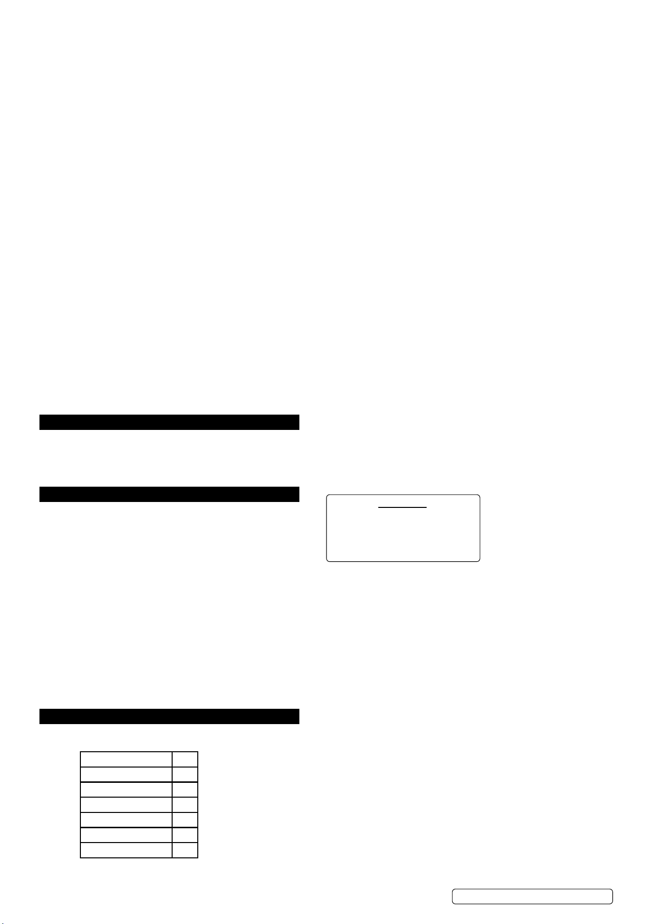
5.1. POWER INDICATOR LIGHT g.1.1
5.1.1. This light will illuminate when the power cord is connected to the mains supply and the power switch, on the rear of the unit, is in the ‘ON’
position.
5.2. WORK INDICATOR fig.1.2
5.2.1. When cutting this light will illuminate to show the cutter is in working mode.
5.3. PROTECTION INDICATOR LIGHT fig.1.3
5.3.1. When the unit is in ‘thermal overload’, is over voltage or lacking voltage, the indicator light will illuminate and the machine will stop
working. When the unit has cooled down and the voltage stabilises, the unit will return to operation automatically.
5.4. EARTH CABLE CONNECTION fig.2.5
5.4.1. The earth cable connects to the workpiece.
5.5. CURRENT ADJUSTMENT fig.1.4
5.5.1. Varies the output cutting current. Higher output is for thicker metal. Maximum cutting thickness is 10mm for this unit. Maximum cutting
thickness varies depending on the material being cut. Refer to Table, fig.3A.
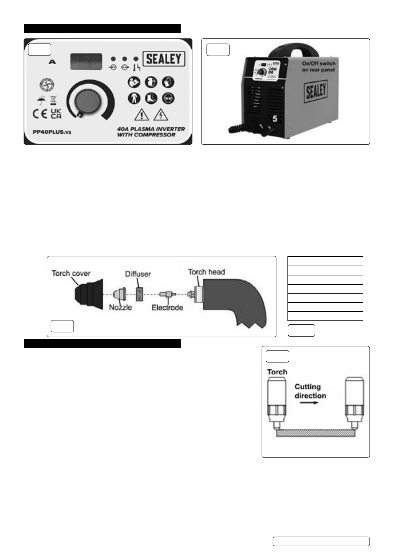
5.6. TORCH
5.6.1. The torch comes fully assembled. Fig.3 below shows how the components are assembled.
6. OPERATION
WARNING! Never allow the torch to be aimed at any part of a body.
9 Make sure to wear full PPE, refer to Safety section, while operating.
9 Work only in well-ventilated areas. If necessary, use exhaust/ventilation fans to keep
fumes or emissions away from the breathing zone.
8 DO NOT touch the work piece while cutting.
6.1. Check the unit to see if it has been connected correctly and is in good working condition.
6.2. Follow all safety advice in Section 1 concerning Electrical and General Safety.
6.3. Switch on the unit and observe if operation is normal: the fan should start up and the
power indication light should be on.
6.4. Pull the trigger: the cutting operation begins after the cutting plasma pilot arc is made.
6.5. CUTTINGg.4
6.5.1. Metal sheet cutting
Connect the earth cable to the workpiece.
Put the torch’s nozzle at the start of the workpiece.
Turn on the torch switch to ignite the plasma pilot.
After the work piece is cut through move the torch along the cutting direction uniformly.
The cutting speed is determined by watching to see if the cut goes all the way through.
If the speed is too fast the workpiece will not be cut all the way through. If the speed is too slow, the quality of the cut will be affected,
excessive warping will occur or the arc could stop.
When nished turn off the torch, the plasma pilot arc will stop.
6.5.2. Metal mesh cutting
Fix the workpiece and connect the earth cable to the workpiece.
Put the cutting nozzle onto the workpiece, lift up the torch slightly and turn on the switch to cut.
6.5.3. Cutting action
Unnecessary igniting of the pilot arc in the air will reduce the life span of the torch’s electrode and nozzle.
Start at the edge of the workpiece unless you are piercing the work piece.
Original Language Version
© Jack Sealey Limited
Material Clean cut
Mild steel 8mm
Stainless steel 6mm
Galvanised 6mm
Aluminium 6mm
Copper 3mm
Brass 3mm
fig.1
fig.2
fig.3
fig.3A
fig.4
PP40PLUS.V2 Issue:2 16/07/24

Keep a space between the nozzle and the workpiece. Pressing the nozzle on the workpiece could cause the nozzle to stick, reducing the
smoothness of the cutting action.
Keep the torch vertical against the workpiece and watch to make sure the arc is moving along the cutting line.
8 DO NOT rapidly switch the torch trigger on and off this will damage the pilot arc system and the work piece.
7. TROUBLESHOOTING
8. ELECTROMAGNETIC COMPATIBILITY
8.1. THIS EQUIPMENT IS IN CONFORMITY WITH THE EUROPEAN STANDARD ON THE ELECTROMAGNETIC COMPATIBILITY
OF ARC WELDING EQUIPMENT AND SIMILAR PROCESSES (e.g. ARC AND PLASMA CUTTING )
8.2. PROTECTION AGAINST INTERFERENCE. (E.M.C.) The emission limits in this standard may not, however, provide full protection
against interference to radio and television reception when the equipment is used closer than 30m to the receiving antenna. In special
cases, when highly susceptible apparatus is being used in close proximity, additional mitigation measures may have to be employed in
order to reduce the electromagnetic emissions.
8.3. INSTALLATION AND USE. The user is responsible for installing and using the equipment according to these instructions. If
electromagnetic disturbances are detected, then it shall be the responsibility of the user of the equipment to resolve the situation with the
technical assistance of the supplier. In some cases this remedial action may be as simple as earthing the circuit (see Note:).
In other cases it could involve constructing an electromagnetic screen, enclosing the welding power source and the work, complete with
associated input filters. In all cases the electromagnetic the electromagnetic disturbances shall be reduced to the point where they are no
longer troublesome. Note: The welding/cutting circuit may or may not be earthed for safety reasons. Changing the earthing arrangements
should only be authorised by a person who is competent to assess whether the changes will increase the risk of injury, e.g. by allowing
parallel welding/cutting circuit return paths which may damage the earth circuits of other equipment.
Original Language Version
© Jack Sealey Limited
Symptom Possible cause Corrective action
Power Indicator
Light is off after
turning on the power
supply.
1. The light is broken.
2. Fuse is blown.
3. Not 230V Input Voltage.
4. Power supply switch is broken.
5. Controlling board or cutter is damaged.
1. Replace.
2. Replace.
3. Connect the 240V Input cable.
4. Replace.
5. Examine and repair.
Fan doesn’t work
after turning on the
power supply.
1. Fan is damaged.
2. Fan’s ground lead is broken.
3. Fan’s blade is blocked
4. Transformer is damaged.
1. Replace.
2. Examine and repair.
3. Clean the block.
4. Replace.
Will not cut 1. Discharge gap is too big.
2. Main controlling board is damaged.
3.Ground lead is broken
1. Adjust to suitable gap.
2. Replace.
3. Replace.
4. Examine and repair.
5. Examine and repair.
No response after
turning on the torch
switch.
1. Switch and ground-lead are broken.
2. Switch board is broken.
3. Main controlling board is damaged.
4. Transformer is damaged.
5. Ground lead is broken.
1. Examine and repair or replace.
2. Examine and repair or replace.
3. Examine and repair or replace.
4. Replace.
5. Examine and repair.
No response after
turning on power
supply.
1. Power cord hooked up wrong.
2. Power supply switch is broken.
3. Fuse is damaged.
4. Transformer is broken.
5. Main controlling board is ruined.
1. Examine and repair.
2. Replace.
3. Replace.
4. Replace.
5. Examine and repair or replace.
Protection indicator
Light comes on.
1. High/low voltage
2. The High/low voltage setting is incorrect.
3. Over heating from exceeding the duty cycle.
4. The bad or broken connection in the thermal relay.
5. Main PCB board is broken.
1. The tolerant voltage range is 200V ~ 250V. The machine
will stop working and indicator will come on if the input power
voltage is not between 220V and 240V AC. Please check the
voltage with a volt meter.
2. Please open the case to adjust the potentiometer RP3 (for
high voltage setting or low voltage setting) on the main control
PCB. Note: RP3 should be adjusted clockwise, the RP3
should be adjusted counter clockwise.
3. Wait until the machine cools down.
4. Repaired by the qualied people.
5. Replace.
PP40PLUS.V2 Issue:2 16/07/24
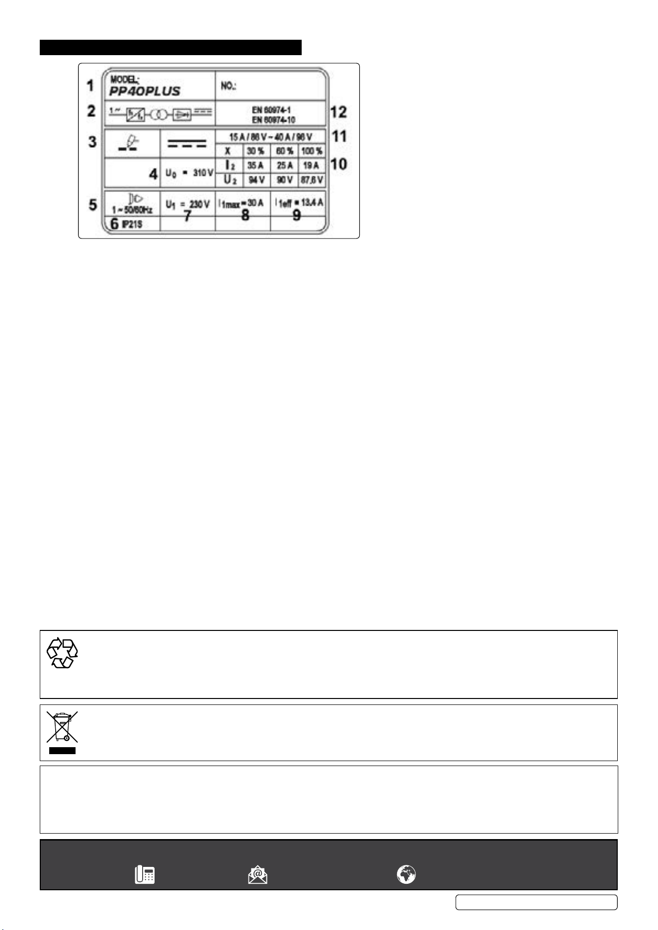
9. RATINGS PLATE
Original Language Version
© Jack Sealey Limited
1 Part number
2 Internal wiring information
3 Plasma symbol
4 Max open circuit voltage
5 AC supply details
6 Insulation protection rating
7 Rated supply voltage
8 Max RMS current absorbed
9 Effective current supplied
10 X Duty cycle based on 10mins (35% indicates 3.5mins cutting 6.5 mins rest, 100% indicates continuous usage.
I
2
, U
2
: current and corresponding voltage.
11 Cutting current range and corresponding voltage.
12 Equipment safety standard.
Sealey Group, Kempson Way, Suffolk Business Park, Bury St Edmunds, Suffolk. IP32 7AR
01284 757500 sales@sealey.co.uk www.sealey.co.uk
ENVIRONMENT PROTECTION
Recycle unwanted materials instead of disposing of them as waste. All tools, accessories and packaging should be sorted, taken to
a recycling centre and disposed of in a manner which is compatible with the environment. When the product becomes completely
unserviceable and requires disposal, drain any fluids (if applicable) into approved containers and dispose of the product and fluids
according to local regulations.
WEEE REGULATIONS
Dispose of this product at the end of its working life in compliance with the EU Directive on Waste Electrical and Electronic Equipment
(WEEE). When the product is no longer required, it must be disposed of in an environmentally protective way. Contact your local solid
waste authority for recycling information.
Note: It is our policy to continually improve products and as such we reserve the right to alter data, specifications and component parts without prior
notice. Please note that other versions of this product are available. If you require documentation for alternative versions, please email or call
our technical team on technical@sealey.co.uk or 01284 757505.
Important: No Liability is accepted for incorrect use of this product.
Warranty: Guarantee is 12 months from purchase date, proof of which is required for any claim.
PP40PLUS.V2 Issue:2 16/07/24