Loading ...
Loading ...
Loading ...
Input and Channel Configuration
Channel Configuration 3
3-23
Digital I/O (DIO) Channel Configuration (Ch401)
The Product can sense and output a digital, 8-bit transistor-transistor logic (TTL) value
that can be displayed as the 8-bit TTL value and be recorded as the decimal equivalent.
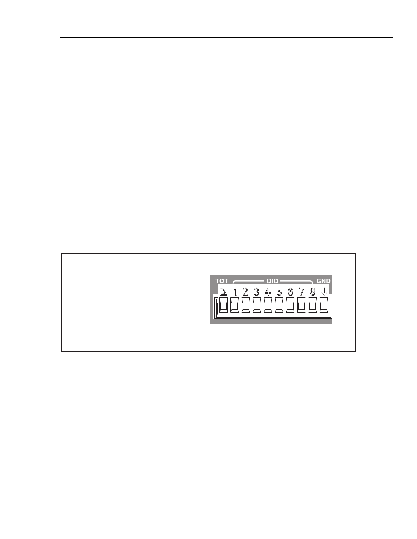
This is accomplished with the rear-panel digital I/O connectors (DIO) that are shown in
Figure 3-7.
When a DIO input is sensed, the Product displays the status of the digital I/O as 8-bit
TTL value and records the decimal equivalent. The 8-bit TTL value can also be seen
when a channel is monitored. The default value is a high state that shows as “11111111”
until the Product senses a low state or is used as an output. A few examples of some 8-bit
TTL values and their decimal equivalents are shown below:
• 11111111 is represented by decimal 255
• 00001111 is represented by decimal 15
• 00010001 is represented by decimal 17
• 10000101 is represented by decimal 133
Notes
For input and output specifications such as input and output voltages, see
“Digital I/O” in Chapter 1.
The DIO channel will be read-only when it is set to ON (active).
With a remote command, the Product can output an 8-bit TTL value. See the
2638A Remote Programmers Guide for more information.
Terminal
TOT
1
2
3
4
5
6
7
8
GND
Function
Totalizer Input
Input/Output Line 1
Input/Output Line 2
Input/Output Line 3
Input/Output Line 4
Input/Output Line 5
Input/Output Line 6
Input/Output Line 7
Input/Output Line 8
Ground Terminal
hcn040.eps
Figure 3-7. DIO Connector
Set up the DIO channel as follows:
1. Connect the equipment to the DIO input terminal then insert it into the rear-panel
digital I/O (DIO) port.
2. Push
.
1.888.610.7664 sales@GlobalTestSupply.com
Fluke-Direct.com
Loading ...
Loading ...
Loading ...