50L AIR OPERATED MOBILE PARTS WASHER
WITH 65L RESERVOIR
MODEL NO: SM224
Thank you for purchasing a Sealey product. Manufactured to a high standard, this product will, if used according to these
instructions, and properly maintained, give you years of trouble free performance.
IMPORTANT: PLEASE READ THESE INSTRUCTIONS CAREFULLY. NOTE THE SAFE OPERATIONAL REQUIREMENTS, WARNINGS & CAUTIONS. USE
THE PRODUCT CORRECTLY AND WITH CARE FOR THE PURPOSE FOR WHICH IT IS INTENDED. FAILURE TO DO SO MAY CAUSE DAMAGE AND/OR
PERSONAL INJURY AND WILL INVALIDATE THE WARRANTY. KEEP THESE INSTRUCTIONS SAFE FOR FUTURE USE.
1. SAFETY
WARNING! Ensure Health & Safety, local authority, general workshop practice regulations are adhered to when using equipment.
WARNING! Installation site must be equipped with suitable re extinguishers (water must not be used) and escape routes.
WARNING! Disconnect the air supply from the tank before changing accessories, servicing or performing any maintenance.
9 Maintain the tank in good condition (use an authorised service agent).
9 Replace or repair damaged parts. Use genuine parts only. Unauthorised parts may be dangerous and will invalidate the warranty.
9 Locate the tank in a suitable work area. Ensure the tank stands on a firm, level surface. Keep area clean and tidy and free from unrelated
materials. Ensure the area is well ventilated and has adequate lighting.
WARNING! Ensure specied air pressure is maintained and not exceeded.
9 Keep air hose away from heat, oil and sharp edges. Check air hose for wear before each use, and ensure that all connections are secure.
WARNING! This tank is recommended for use only with degreasing solvents suitable for air operated tanks. Ensure you follow makers
instructions for solvent use.
9 Ensure solvent flash point is above 140°F. We recommend you use Sealey solvent - contact your local dealer for details.
9 Keep the tank clean. Remove and clean the tank filters regularly for best performance.
WARNING! DO NOT SMOKE and keep sources of ignition, such as heaters, lamps, etc., away from the unit, together with ammable
or combustible materials, as there is an explosion risk.
9 When cleaning parts ensure that nothing in the tank, including any parts basket, is in a position that would prevent the lid from closing
fully if and when the fusible link activates.
WARNING! DO NOT modify the lid or jam it open. Keep the lid and holding screws in place, tight and in good working order.
WARNING! DO NOT attempt to perform welding on the unit for any reason. DO NOT weld near the unit.
WARNING! Wear approved safety eye protection, mask and gloves. If solvent gets on skin or in eyes wash thoroughly with water and
take any other action as required by the solvent instructions.
9 Remove ill tting clothing, ties, watches, rings and other loose jewellery, contain long hair and wear appropriate protective clothing.
9 Maintain correct balance and footing. Ensure the oor is not slippery and wear non-slip shoes.
9 Keep non-essential persons away from the working area.
9 In case of re in tank, DO NOT attempt to move unit or remove parts from tank. The lid is fusible and will automatically close
extinguishing the re.
9 Disconnect the unit from the air supply when not in use.
8 DO NOT use the tank for any purpose other than that for which it is designed.
8 DO NOT operate the tank if any parts are missing or damaged as this may cause failure and/or personal injury.
8 DO NOT over-fill the tank.
8 DO NOT modify or jam the parts washer lid open, as this will make the fusible fire link inoperative which is dangerous practice and will
invalidate the warranty and your insurance.
8 DO NOT use air line to blow dry components in tank. Only use air gun supplied. DO NOT direct air gun at yourself or others.
8 DO NOT leave the parts washer operating unattended.
9 When cleaning is complete, ensure all controls are in the ‘off’ position and that the air supply is disconnected.
WARNING! It is owner’s responsibility to ensure that there is no uncontrolled discharge of any uids used with this unit and that
appropriate arrangements have been made for correct disposal of waste in accordance with government/local authority regulations.
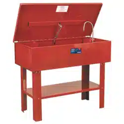
2. INTRODUCTION
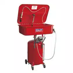
Steel fabricated 65L reservoir and 50L one-piece tank. Mobile unit with two castors and two fixed
wheels, can easily be taken to work area. Air operated unit can be charged and used remotely without
air supply for a limited period. Includes brush for cleaning workpiece and air blow gun for fast drying.
Reservoir fitted with fluid level indicator and drain tap. Supplied with removable shelf and tray. Lid fitted
with fusible link which automatically snaps lid shut in the event of a fire.
3. SPECIFICATION
MODEL NO: SM224 Operating Pressure: 40-60psi
Air Consumption: 6cfm Overall Dimensions (W x D x H): 775 x 485 x 1040mm
Inlet Size: 1/4”BSP Pump Output/hr: 140L
Max. Working Capacity: 50L Supply: Air
Nett Weight: 39.6kg Tank Dimensions (W x D x H): 775 x 485 x 180mm
Refer to
instructions
Wear eye
protection
Wear protective
gloves
Wear protective
clothing
Wear a mask
Warning!
SM224 Issue 5 14/05/24
Original Language Version
© Jack Sealey Limited
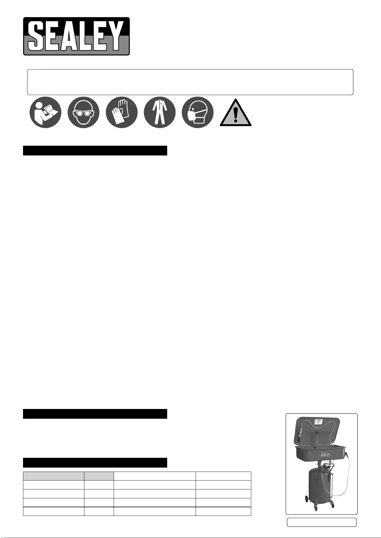
4. ASSEMBLY
4.1. As you unpack the product, check contents. Should there be any
damaged or missing parts contact your supplier immediately.
4.2. Assemble the gate valve (A) which connects the tank to the
reservoir, directly to the reservoir as shown in g.1, ensuring that
a rubber seal is tted to both ends of the valve.
4.3. Screw the air regulator and safety valve assembly (B) to the
reservoir as shown in g.2 ensuring that the rubber seal provided
is in place.
4.4. Assemble the two upper tank support arms (C) into the sockets
provided on the tank but do not tighten the ttings yet.
4.5. Place the upper tank onto the support arms and lower it down
until the tank outlet drops into the top of the gate valve (A). Fix the
tank to the valve by tightening ring (Q) as shown in g.4. Tighten
the hex socket bolts at either end of the upper tank supports (C).
Fit handle into support arm brackets (C) and tighten.
4.6. Mount the cleaning brush in its stowage position on the underside
of the lid over to the left hand side. Feed the brush tube (T)
through the hole in the right-hand side of the tank and connect it
to outlet (R) on the head of the regulator /safety valve assembly.
5. AIR SUPPLY
5.1. Ensure that the air regulator valve is closed before connecting the air supply.
5.2. An air pressure of 40-60psi and an available air volume of 6cfm will be required to operate the unit.
WARNING! Ensure air supply is clean and does not exceed 110psi. Too high an air pressure and/or unclean air will shorten the product
life, and may be dangerous, causing possible damage and/or personal injury.
Air supply must be equipped with regulator & water trap.
5.3. Drain the air supply tank daily. Water in the air line will damage the unit.
5.4. Clean the air supply filter weekly. For recommended hook-up, see diagram below.
5.5. Line pressure should be increased to compensate for unusually long air hoses (over 8 metres). The minimum hose internal diameter
should be 10mm and fittings must have the same internal dimension.
5.6. Keep hose away from heat, oil and sharp edges. Check hoses for wear, and make certain that all connections are secure.
5.7. The air inlet connection is 1/4”BSP.
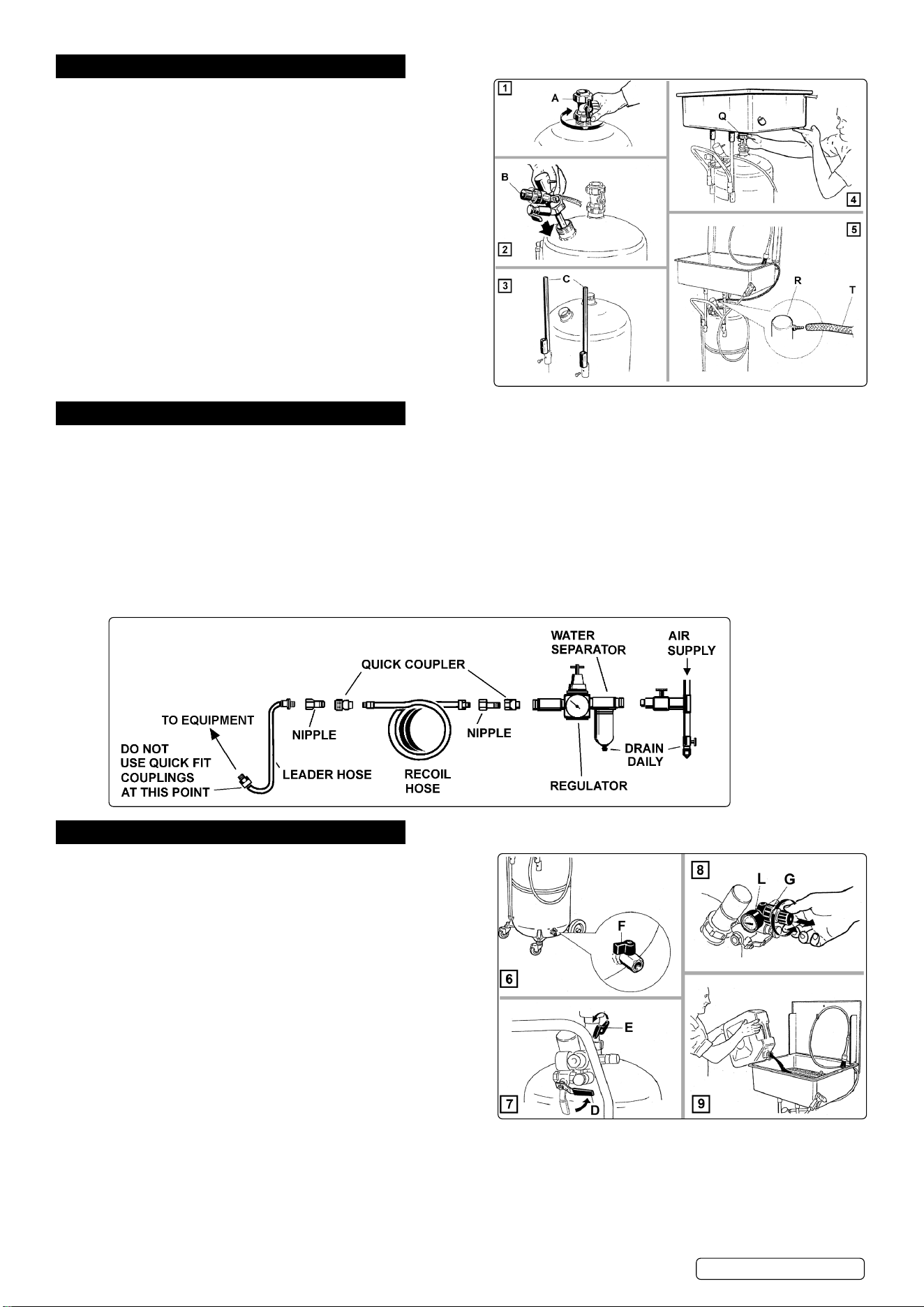
6. OPERATION
6.1. FILLING THE UNIT WITH CLEANING FLUID
6.1.1. Make sure that the drain cock at the base of the unit is closed as
shown at (F) in fig.6.
6.1.2. Turn the lever (D) to the right which is the air discharge position.
This allows the fluid to drain more easily out of the upper tank
and into the lower reservoir. See fig.7. Open the gate valve (E) by
turning the lever to the vertical position.
6.1.3. Shut the pressure regulator by pulling and turning the pressure
regulator knob (G) anticlockwise. See fig.8.
6.1.4. Pour cleaning fluid into the upper tank and allow it to drain down into
the lower reservoir. Continue to fill the unit until the level has risen to
the maximum mark on the level indicator tube.
6.1.5. Before using the unit ensure that all filter grids are in place.
WARNING! Wear approved safety eye protection, mask and
gloves. If solvent gets on skin or in eyes wash thoroughly with
water and take any other action as required by the solvent
instructions.
6.2. COMMENCING BRUSH WASHING
6.2.1. Close the gate valve (E) and turn lever (D) to the left as shown in fig.10.
6.2.2. Connect a compressed air line to the connector shown in fig.11.
6.2.3. Pre-set the air pressure by pulling and turning the air regulator knob clockwise until the gauge shows a pressure between 90 & 110psi.
6.2.4. Turn the flow regulator (M) anticlockwise until fluid flows from the brush. See fig.12.
SM224 Issue 5 14/05/24
Original Language Version
© Jack Sealey Limited
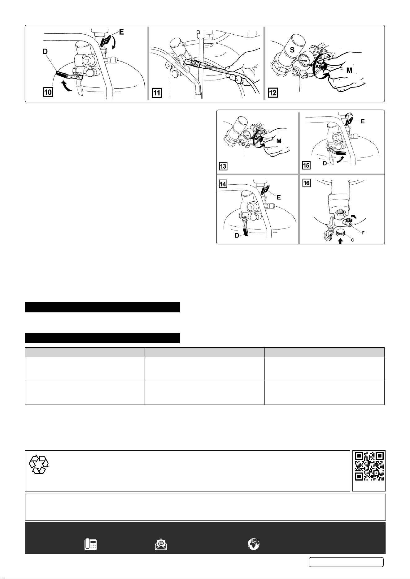
6.3. SAFETY VALVE
6.3.1. The uid outlet head (S) shown in g.12 is a movable, weighted
item that acts as a safety valve. If the ow regulator (M) is
opened too much, excess air will be discharged from underneath
the head. Take care to set the ow regulator (M) to an adequate
but not excessive ow of air.
6.4. AIR BLOW GUN
6.4.1. The unit is also equipped with an air blow gun for drying
components after cleaning. When the nozzle of the gun is
twisted clockwise the gun is shut off. When the nozzle is twisted
anticlockwise the gun is on. The first movement of the trigger
produces a medium flow of air. When the trigger reaches its full
travel the air flow changes to a more gentle blow.
6.5. WASHING BY DIPPING
6.5.1. Open the gate valve (E) and turn lever (D) to the left as shown in
fig.10. The cleaning fluid will rise from the reservoir into the tank
and will be kept in constant motion by the air passing through the
liquid itself.
6.5.2. The intensity of the agitation can be adjusted by means of the flow
regulator (M).
WARNING! DO NOT allow excessive agitation to take place as
this may cause splashing and overlling of the tank.
6.5.3. To turn the agitation off, close the gate valve and turn the lever (D) to the middle position.
6.5.4. To return the fluid to the reservoir, turn lever (D) to the right and open gate valve (E).
6.5.5. To empty the reservoir, open the drain cock (F).
When cleaning parts ensure that nothing in the tank, including any parts basket, is in a position that would prevent the lid
from closing fully if and when the fusible link activates.
7. MAINTENANCE
7.1. From time to time clean the grids in the bottom of the tank.
7.2. Waste deposits that accumulate in the bottom of the reservoir can be removed by removing drain plug (G).
8. TROUBLESHOOTING
PROBLEM CAUSE SOLUTION
Liquid fails to come out of the brush Insufcient liquid in reservoir
Insufcient air pressure
Lever D in wrong position
Fill
Check air connection A, pressure regulator
Turn lever to left position as shown in g. 10
Dirty uid comes out of the brush Blocked lters
Fluid too old and dirty
Contaminated lters
Clean lters
Drain off old uid and replace with clean
Clean tank lters
Sealey Group, Kempson Way, Suffolk Business Park, Bury St Edmunds, Suffolk. IP32 7AR
01284 757500 sales@sealey.co.uk www.sealey.co.uk
Note: It is our policy to continually improve products and as such we reserve the right to alter data, specications and component parts without prior notice.
Important: No Liability is accepted for incorrect use of this product.
Warranty: Guarantee is 12 months from purchase date, proof of which is required for any claim.
ENVIRONMENT PROTECTION
Recycle unwanted materials instead of disposing of them as waste. All tools, accessories and packaging should be
sorted, taken to a recycling centre and disposed of in a manner which is compatible with the environment. When
the product becomes completely unserviceable and requires disposal, drain any uids (if applicable) into approved
containers and dispose of the product and uids according to local regulations.
REGISTER YOUR
PURCHASE HERE
SM224 Issue 5 14/05/24
Original Language Version
© Jack Sealey Limited