WALL CONTROLLER - 3 IN 1
INTRODUCTION & WARRANTY
FEATURES
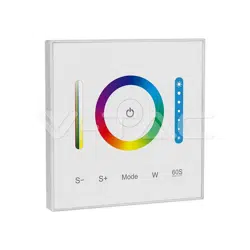
PARTS OF DESCRIPTION
CONTROLLER FUNCTIONS
Thank you for selecting and buying V-TAC product. V-TAC will serve you the best. Please read these instructions
carefully before starting the installation and keep this manual handy for future reference. If you have any
another query, please contact our dealer or local vendor from whom you have purchased the product. They are
trained and ready to serve you at the best. The warranty is valid for 2 years from the date of purchase. The
warranty does not apply to damage caused by incorrect installation or abnormal wear and tear. The company
gives no warranty against damage to any surface due to incorrect removal and installation of the product. The
products are suitable for 10-12 Hours Daily operation. Usage of product for 24 Hours a day would void the
warranty. This product is warranted for manufacturing defects only.
IN CASE OF ANY QUERY/ISSUE WITH THE PRODUCT, PLEASE REACH OUT TO US AT: SUPPORT@V-TAC.EU
FOR MORE PRODUCTS RANGE, INQUIRY PLEASE CONTACT OUR DISTRIBUTOR OR NEAREST
DEALERS. V-TAC EUROPE LTD. BULGARIA, PLOVDIV 4000, BUL.L.KARAVELOW 9B
WARNING!
1. Please make sure to turn off the power before starting the installation.
2. Installation should only be done by a certified electrician.
3. For Indoor use only
4. Please check whether the voltage of the power supply is in accordance with the controller, and please check
the connection of both the cathode and anode, otherwise the controller will be broken.
5. Please don’t connect wires with power on. Please turn on again only when it is in right connection and no
short circuit.
6. Please do not use the controller in the place with widely range metal area or strong electromagnetic wave
nearby, otherwise, the remote distance will be seriously affected.
Caution, risk of electric shock.
This marking indicates that this
product should not be disposed
of with other household wastes.
TECHNICAL DATA:
2
YEARS
WARRANTY
*
MODEL VT-2433
INPUT/OUTPUT VOLTAGE
DC12V~24V
TOATL OUTPUT
MAX 10A
OUTPUT CURRENT 5A/CHANNEL
RF 2.4GHz
OPERATION
TEMPERATURE
-10°C to +40°C
CONTROL DISTANCE
30m
DIMENSION
86x86mm
Dim brightness / Saturation
Color temperature adjustable
2.4G RF wireless transmission
technology
Remote control Control distance 30m
Support third party voice control
(2.4GHz gateway is needed)
DMX512 controllable
(DMX512 LED transmitter is needed)
Smartphone app control
(2.4GHz gateway is needed)
16 Millions of colors to choose
Speed-
Speed+
Saturation/
Color Temp.
Slider
Mode
ON / OFF
White mode
Brightness Slider
60S Delay OFF
Color Ring
This controller is compatible with RGB,RGBW and RGB+CCT version. It will be RGB+CCT version
when you get it first time.
Method of Switching RGB, RGBW and RGB+CCT version
1. When the light is OFF, long press “ Mode ” and “ W ” button at the same time, the controller will
sound 3 times after 5 seconds, then it change to RGB version.
2. When the light is OFF, long press “ W ” and “ ” button at the same time, the controller will
sound 4 times after 5 seconds, then it change to RGBW version.
3. When the light is OFF, long press “ Mode ” and “ ” button at the sametime, the controller will
sound 5 times after 5 seconds, then it change to RGB+CCT version.
BUTTON FUNCTIONS
Mode
S-
S+
1. Short press ON / OFF switching
2. Long press to turn on night light while light is on.
3. Short press twice to enter the learning code state (see 8, 9 for details) while light is
on.Press “ W ”, switch to static white light mode.
When the light is ON, press “ ”, the light will be off automatically after 60 seconds.
Touch color ring, choose the color you want.
Touch dimming slider to change the brightness from
1%~100%.
Each modes have their own brightness value and saturation value
(Static white light mode and dynamic white light gradual changing mode have no
saturation ) function see details for P3 Mode table.
1. Press “ Mode ” shortly, switch to next mode; long press “ Mode ”, switch the modes
circularly, there are 12 kind modes. (PS, on the color light, press mode, it will get to first
mode).
2. In the version of RGB+CCT, white gradual changing mode means CCT gradual
changing under static white mode.
1. Slow the speed on present dynamic mode. There is 5 class speed. Long press “ S- ”,
slow the speed
continuously. When it get to slowest speed, “ S- ” will be invalid. (Dynamic mode see
details for P3 Mode table.)
2. When light is OFF, long press 5 seconds to turn OFF the indicating sound.
1. Accelerate the speed on present dynamic mode. There is 5 class speed. Long press
“S+”, accelerate the
speed continuously. When it get to fastest speed, “S+” will be invalid. (Dynamic mode
see details for P3 Mode table.)
2. When light is OFF, long press 5 seconds to turn ON the indicating sound.
W
Switch to high frequency (8KHz): on the condition of turning on the light
1. Short press the “OFF” button of the remote control once;
2. Short press the “ON” button of the remote control 5 times within 3 seconds, the white light blink
2 times quickly, indicating successfully.
Switch to low frequency (500Hz): on the condition of turning off the light
1. Short press the “ON” button of the remote control once;
2. Short press the “OFF” button of the remote control 5 times within 3 seconds, the white light
blink 2 times slowly, indicating successfully.
PWM HIGH FREQUENCY / LOW FREQUENCY SWITCHING
P3 MODE TABLE 1 (DEFAULT)
P3 MODE TABLE 2 (NEED TO SWITCH MANUALLY)
STATE NO MODE
BRIGHTNESS / SATURATION /
SPEED
1 RED
2 GREEN
3 BLUE
4 MARDI GRAS
5 AUTOMATIC COLOR CHANGE
6 SAM
7 GEMSTONE
8 TWILIG HT
9 AMERICAN
10 FAT TUESDAY
11 PARTY
12 SLOW COLOR SPLASH
ADJUSTABLE
ADJUSTABLE
(SPEED IS NOT ADJUSTABLE)
STATIC MODE
(NOT APPLICABLE TO
REMOTE CONTROLLER)
DYNAMIC MODE
STATE NO MODE
BRIGHTNESS / SATURATION /
SPEED
1
RED
2
GREEN
3
BLUE
4
COLORS GRADUAL CHANGE ADJUSTABLE SATURATION
5
WHITE LIGHT GRADUAL
CHANGE
SATURATION IS NOT
ADJUSTABLE
6
RGB GRADUAL CHANGE
7
SEVEN COLORS JUMP TO
CHANGE
8
JUMP TO CHANGE RANDOMLY
9
RED LIGHT GRADUAL CHANGE
+ FLASH 3 TIMES
10
GREEN LIGHT GRADUAL
CHANGE + FLASH 3 TIMES
11
BLUE LIGHT GRADUAL CHANGE
+ FLASH 3 TIMES
12
WHITE LIGHT GRADUAL
CHANGE + FLASH 3 TIMES
DYNAMIC MODE
ADJUSTABLE
STATIC MODE
(NOT APPLICABLE TO
REMOTE CONTROLLER)
ADJUSTABLE
(SPEED IS NOT ADJUSTABLE)
6. DYNAMIC MODE TABLE SELECTION (REMOTE CONTROL ONLY)
Select dynamic mode table 1: press " " 2 times continuously
when light is on, Within 3 seconds, press the " S+ " button of the remote control 5 times, the blue
light blink 3 times slowly , indicating successfully.
Select dynamic mode table 2: press " " 2 times continuously
when light is on, Within 3 seconds, press the " S- " button of the remote control 5 times, the yellow
light blink 3 times slowly, indicating successfully.
LINKING/UNLINKING DEVICES
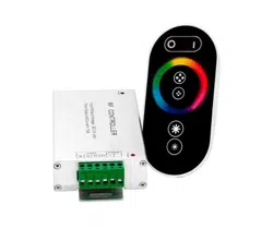
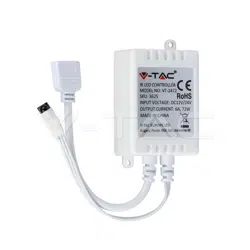
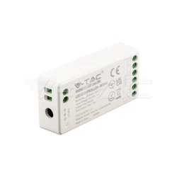
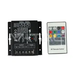
Compatible with the below devices (Not included; available to buy separately)
(SKU: 2921
VT-2438)
(NOT INCLUDED)
(SKU: 2922
VT-2441)
(NOT INCLUDED)
(SKU: 2923 / 2924
VT-2442)
(NOT INCLUDED)
(SKU: 2917
VT-2437)
(NOT INCLUDED)
Light will work after linking with remote control;
for more details, please read the remote instruction.
(SKU: 2921 - VT-2438)
(NOT INCLUDED)
Support all remote control to do Link/Unlink (see 7 for details)
REMOTE CONTROL LINKING/UNLINKING
2
1
Power
LED Light
Link/Unlink
Button
LINK
• Press " " 2 times continuously when light is on
• Press the remote control within 3 seconds " " key 3 times
• The light blink 3 times slowly means the linking is done successfully
• Press " " 2 times continuously when light is on
• Press the remote control within 3 seconds " " key 5 times
• The light blink 10 times quickly means the unlinking successfully
UNLINK
LINK
• Press " " 2 times continuously when light is on
• Press the remote control within 3 seconds " " key 3 times
• The light blink 3 times slowly means the linking is done successfully
• Press " " 2 times continuously when light is on
• Short press " " 5 times within 3 seconds
• The light blink 10 times quickly means the unlinking successfully
UNLINK
If the link or unlink failed, please follow the above steps again.
Compatible with DMX512 LED Transmitter (Not included. Can purchase outside)
DMX512 LED TRANSMITTER LINKING/UNLINKING
3
Link/Unlink button
+
SET
-
SET
SET
SET
Choose the zone for the controller by pressing ‘ + ’ or ‘ - ’ (e.g. ‘CH12’ means zone
12)
1
2
Power
LED Light
SIGNAL TRANSMITTING
One strip controller can transmit the signals from the remote control to another controller within
30m, as long as there is a strip controller within 30m, the remote control distance can be
limitless.
P3
P3
Distance 30m
Different controllers can work synchronously when they are started at different
times, controlled by the same remote, under same dynamic mode and within 30m
distance.
MODES SYNCHRONIZATION
Signal transmitting & Modes synchronization
The same dynamic mode, the same speed can be synchronized.
DMX512 LED TRANSMITTER CONNECTION DIAGRAM
DMX512
Control Panel
Connect
DMX512 Transmitter
2.4GHz Wireless Signal
1
Zone
Limitless
Limitless
16
Zone
8.8.8.8
+
SET
-
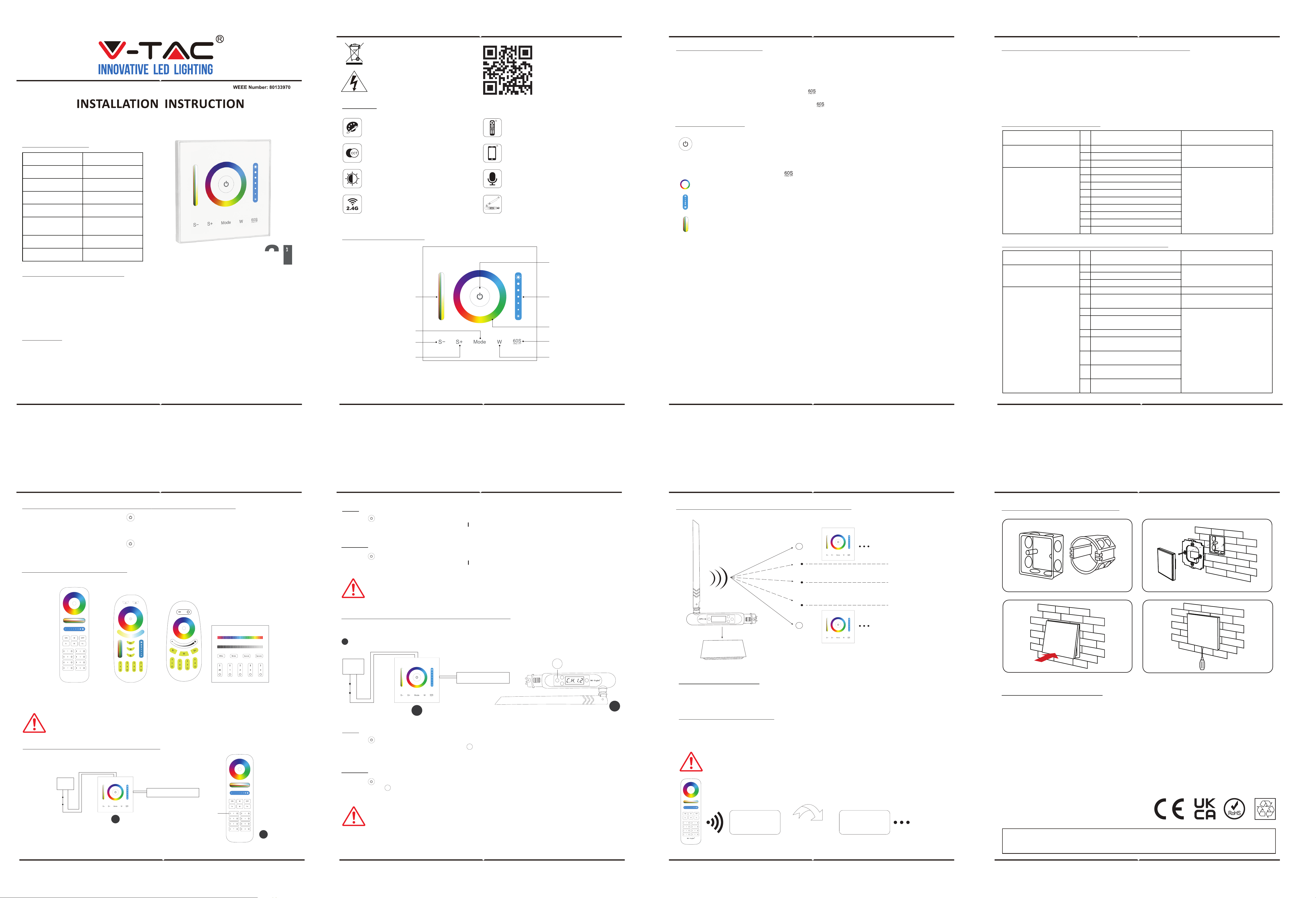
INSTALLATION / DISMANTLEMENT
INSTALLATION INSTRUCTION
1. Install the bottom case into the wall; Above are the standard bottom cases.
2. Fix the controller base on the bottom case with screw.
3. Clicks into the upper side of glass panel on the controller base, then press the lower side
slightly to make it clicks into the controller base.
4. Plug into the below bayonet with a screwdriver, and upwarp screwdriver, then you can
dismantle the controller.
Dismantle
If the link or unlink failed, please follow the above steps again.
2
RS
MULTI-LANGUAGE
MANUAL QR CODE
Please scan the QR code
to access the manual in
multiple languages.