1
Sainlogic FT0300 Professional WIFI Weather
Station with Wireless 8 Channel Remote
Monitoring User Manual
1. Introduction
Thank you for your purchase of the FT0300 Professional WIFI Wireless
Weather station. The following user guide provides step by step
instructions for installation, operation and troubleshooting.
2. Warnings
Warning: Any metal object may attract a lightning strike, including
your weather station mounting pole. Never install the weather station
during a storm.
Warning: Installing your weather station in an elevated location
may result in injury or death. Safety goes first. Make sure your setup
and preparation is secure, and take no risks.
3. Getting Started
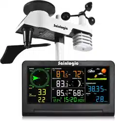
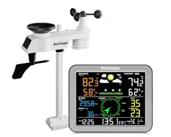
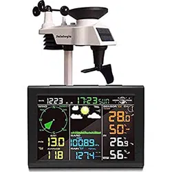
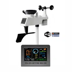
The FT0300 weather station consists of a display console (receiver), a
sensor array with Integrated Outdoor Transmitter and mounting
hardware.
Parts List
The FT0300 weather station consists of the following parts (as
referenced in Figure 1 ).
QTY
Item
Image
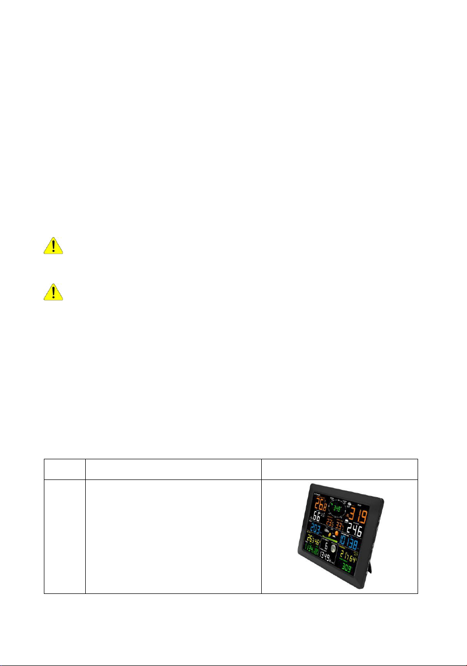
1
Display Console Frame
Dimensions (LxHxW):
215 x 22 x 158mm
LCD Dimensions (LxW):
170 x 125mm
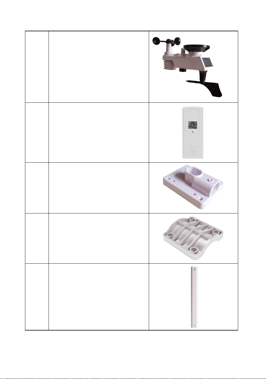
2
1
Integrated Outdoor Transmitter
Dimensions
(LxHxW):330x150x280mm
1
Thermo-hygrometer transmitter
(FT007TH)
Dimensions (LxHxW): 114.5 x
50.0 x 19mm
1
Foot Mounting (with pole
insert)
Dimensions: 101x 76 x 32mm
1
Mounting Bracket Back Plate
(pole mount)
Dimensions: 76 x 102 x 38mm
1
Mounting Pole
Dimensions: 300 x 300 x
20mm
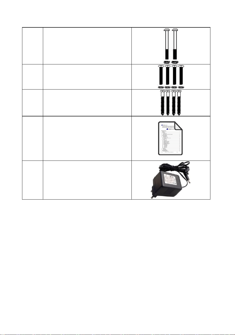
3
2
Pole mounting nuts (M3) / bolts
Ø3)
4
Pole mounting nuts (M5) / bolts
( Ø5)
4
Tapping screws
1
Manual
1
Power Adapter
Figure 1
3.2 Recommended Tools
● Precision screwdriver (for small Phillips screws)
● Compass or GPS (for wind direction calibration)
● Adjustable Wrench
● Hammer and nail for hanging remote thermo-hygrometer
transmitter.
4
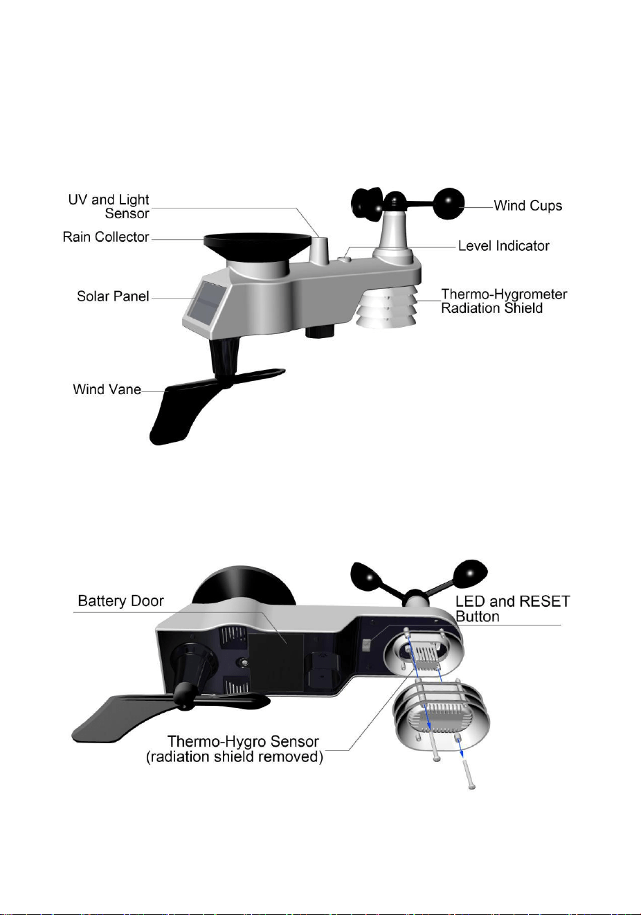
3.3 Setup of Sensor
The following illustration shows the full segment for Thermo-Hygrometer
,WIND,RAIN and UV INDEX sensor. purposes only ,as shown in
Figure 2.
Figure 2
3.3.1 Insert batteries into the transmitter. Locate the battery
cover on the transmitter, push and open the battery compartment, as
show in Figure 3.
Figure 3
5
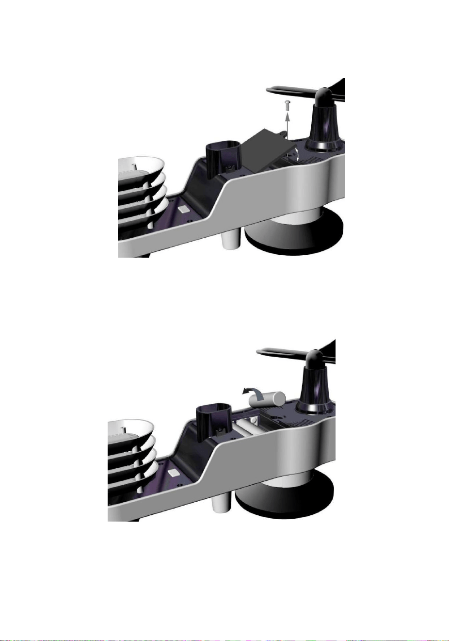
Remove the battery cover on the back of the sensor by removing the
set screw, as shown in Figure 4.
Figure 4
Inserting 3xAA batteries in the battery compartment, as show in Figure
5.
Figure 5
6
Close the battery cover. Make sure the gasket (around the battery
compartment) is properly seated in its place prior to closing the door.
Tighten the set screw.
Note: Do not install the batteries backwards. You can permanently
damage the sensors. The solar panel does not charge the batteries, so
rechargeable batteries are not needed or recommended.
Note: We recommend installing Lithium AA batteries for sensors.
The sensor LED indicator will light for 3 seconds, and then flash once
per 16 seconds thereafter. Each time it flashes, the sensor is
transmitting data.
Place the battery cover and push it to close the compartment.
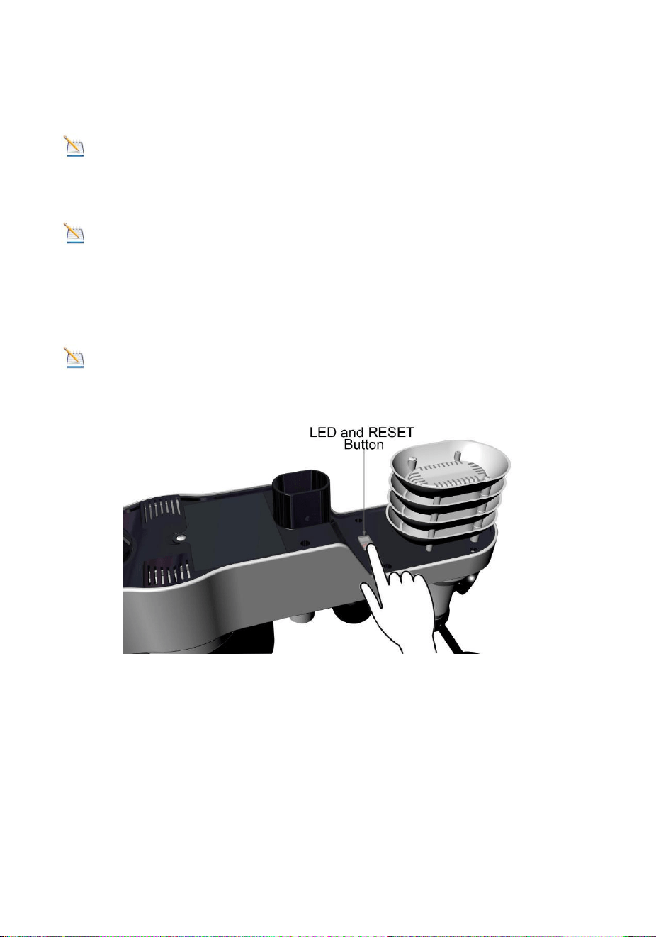
Note: If the sensor does not power up after inserting the batteries,
press the reset button shown in Figure 6.
Figure 6
3.3.2 Insert batteries into the thermo-hygrometer
transmitter. Remove the battery cover on the back of the sensor by
removing the set screw, as shown in Figure 7.
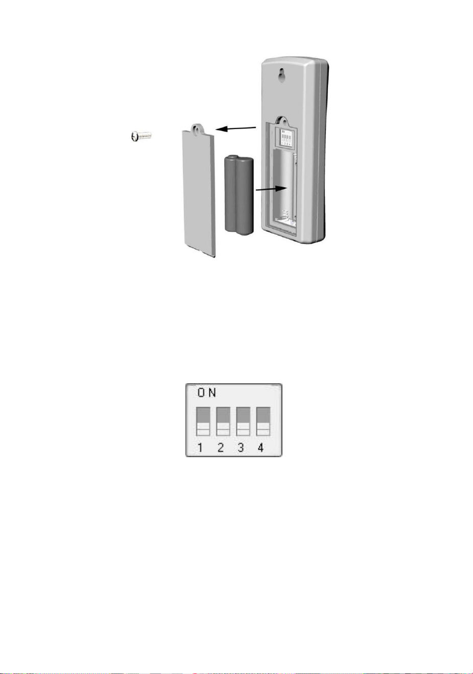
7
Figure 7
1. BEFORE inserting the batteries, locate the dip switches on the
inside cover of the lid of the transmitter.
Figure 8 displays all four switches in the OFF position (factory
default setting).
Figure8
2. Channel Number: The FT0300 supports up to eight
transmitters. To set each channel number (the default is
Channel 1), change Dip Switches 1, 2 and 3, as referenced in
Table 1.
3. Temperature Units of Measure: To change the transmitter
display units of measure (°F vs. °C), change Dip Switch 4, as
referenced in Table 1.
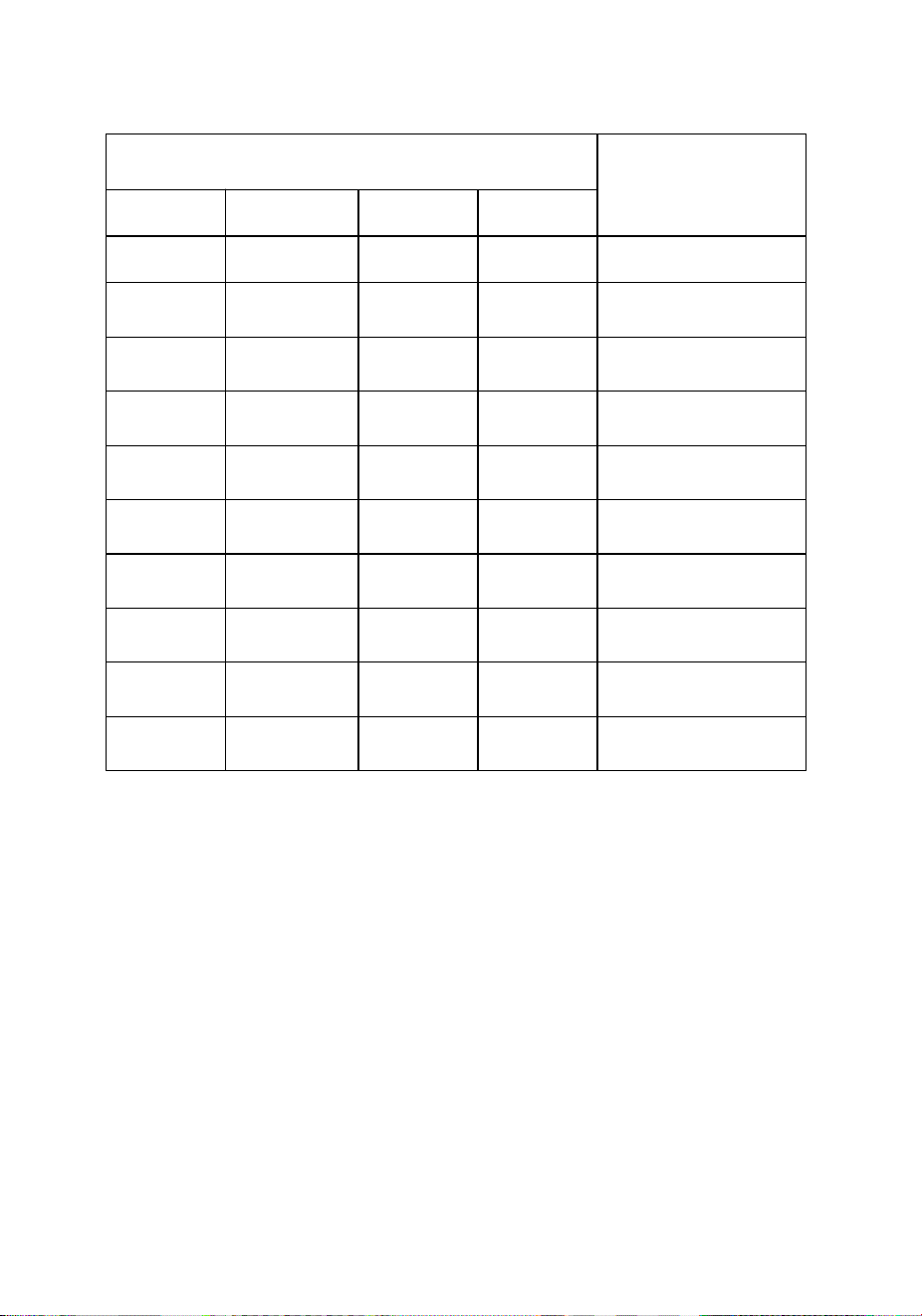
8
DIP SWITCH
FUNCTION
1
2
3
4
DOWN
DOWN
DOWN
---
Channel 1
DOWN
DOWN
UP
---
Channel 2
DOWN
UP
DOWN
---
Channel 3
DOWN
UP
UP
---
Channel 4
UP
DOWN
DOWN
---
Channel 5
UP
DOWN
UP
---
Channel 6
UP
UP
DOWN
---
Channel 7
UP
UP
UP
---
Channel 8
---
---
---
DOWN
°F
---
---
---
UP
°C
Table 1
4. Insert two AAA batteries.
5. After inserting the batteries, the remote sensor LED indicator
will light for 4 seconds, and then flash once per 60 seconds
thereafter. Each time it flashes, the sensor is transmitting data.
6. Verify the correct channel number (CH) and temperature units
of measure (°F vs. °C) are on the display, as shown in Figure 9.
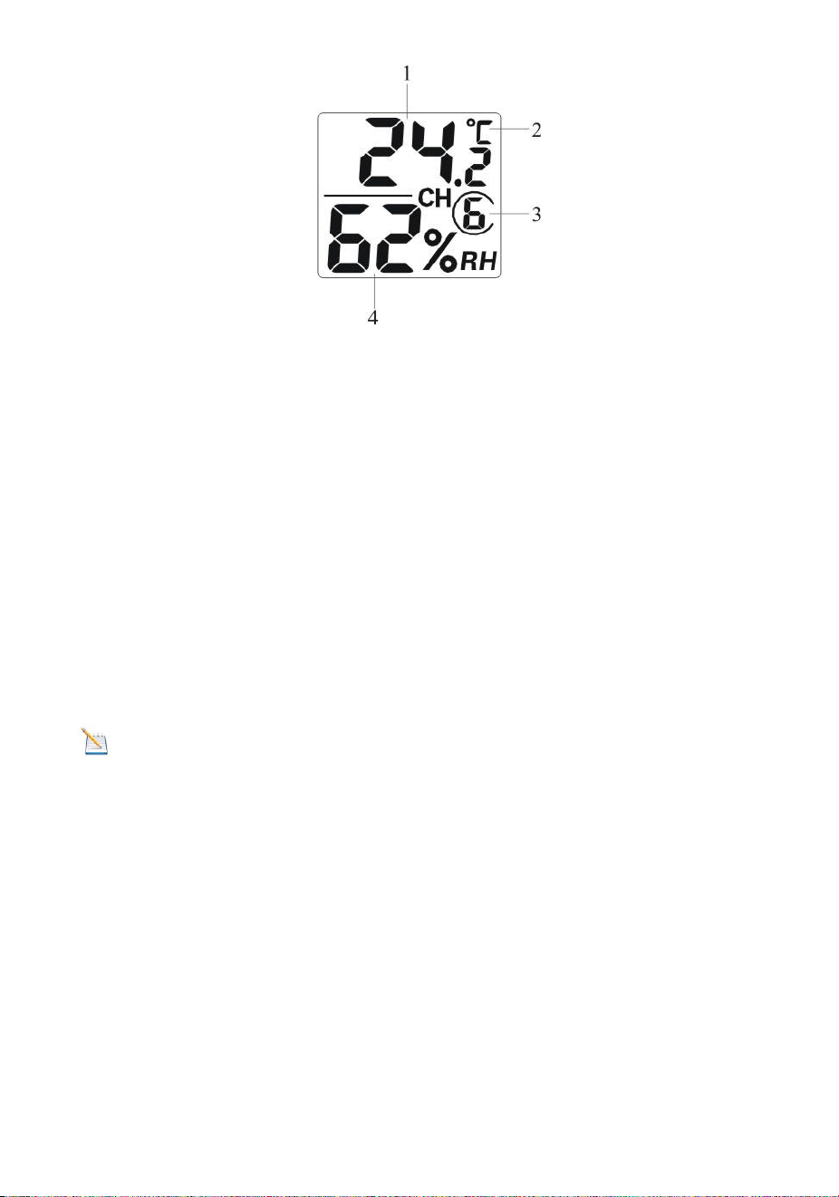
9
Figure 9
(1) temperature
(2) temperature units (°F vs. °C)
(3) channel number
(4) relative humidity
7. Close the battery cover. Make sure the gasket (around the
battery compartment) is properly seated in place prior to closing
the door. Tighten the set screw.
3.4 Display Console
3.4.1 Display Console Layout
The display console layout is shown in Figure 10
Note: The following illustration shows the full segment LCD display
for description purposes only and will not appear like this during normal
operation.
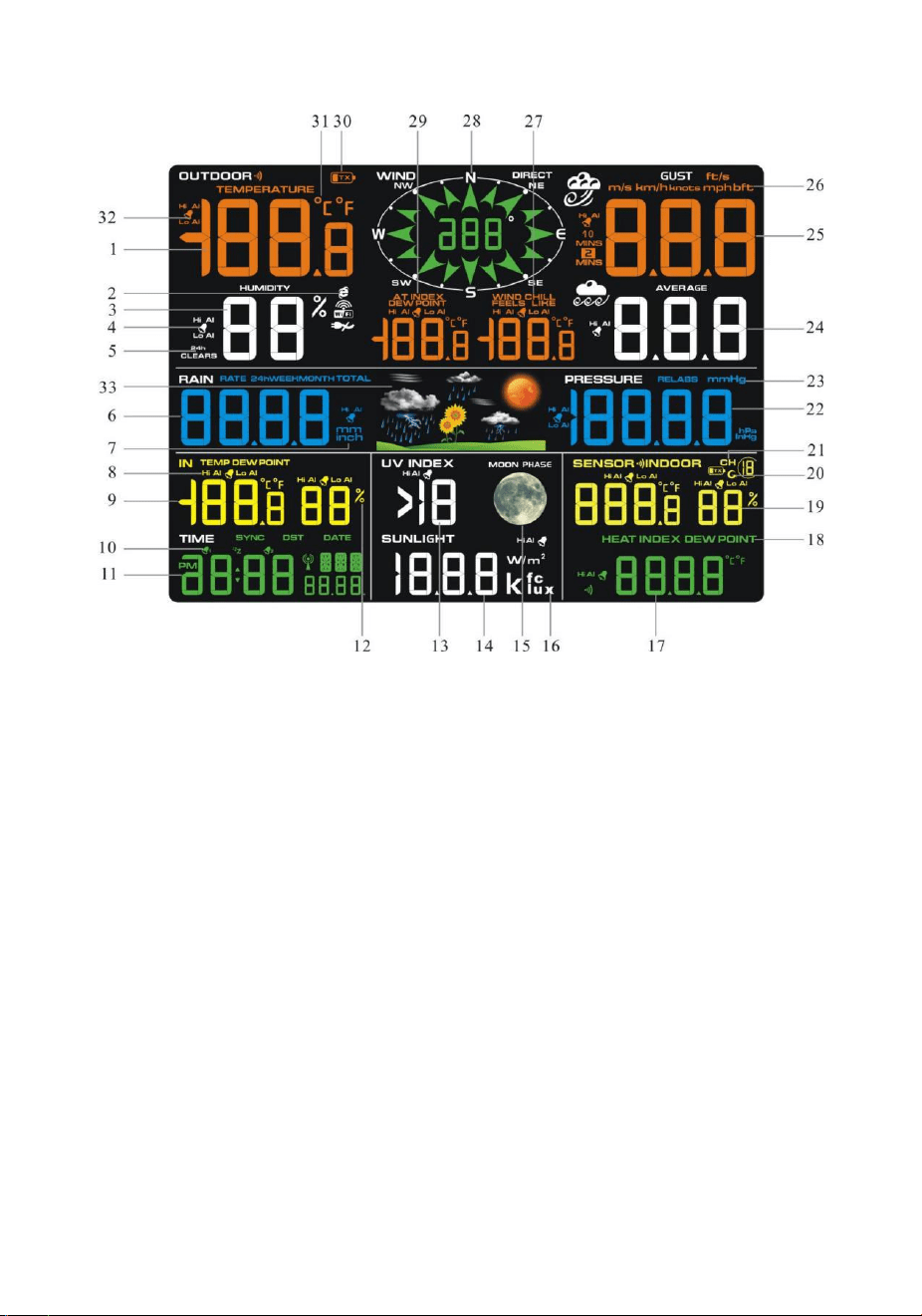
10
Figure 10
1. Outdoor temperature display
2. WIFI network
3. Outdoor humidity display
4. Outdoor humidity HI/LO alarm
icon
5. Min/Max reset for 24h icon
6. Rainfall display(RATE, 24h,
WEEK,MONTH, TOTAL)
7. Rainfall units of measure
8. Indoor temperature and
humidity HI/LO alarm icon
9. Indoor temperature and
humidity display
10. Time alarm icon
11. Time and date
12. Humidity units of measure (%)
13. UV Index display
14. Sunshine intensity
15. MOON phase
16. Sunlight units of measure
17. Sensor Heat index display
18. Sensor Heat index(heat index; dew
point)
19. Outdoor temperature and humidity
display
20. Scroll mode indicator
21. Channel 1-8 indicator
22. Pressure (REL and ABS) display
23. Pressure units of measure
24. Wind speed average display
25.Wind gust display
26.Wind speed units of measure
27.Wind chill and feels like HI/Lo alarm icon
28. Wind direction
29. OUT dew point and AT(Apparent
Temperature) display icon
30. Integrated outdoor transmitter Low power
indicator
31.Temperature units (°F or °C)
32.Outdoor temperature HI/LO alarm icon
33.Weather forecast
11
3.4.2 Display Console Set Up
It is recommended to plug in the power supply to reduce the
battery consumption and extend the service life.
Note: The sensor array must be powered and updating before
powering up the console, or the console will time out searching for the
sensors. Power the console last.
Make certain the weather station sensor array is at least 3m away from
the console and within
30m of the console. If the weather station is too close or too far away, it
may not receive a proper signal. If you have more than one Thermo-
hygrometer transmitter, make sure they are all powered up and
transmitting on different channels.
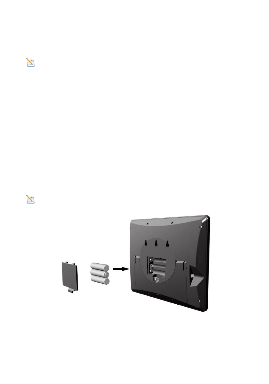
Remove the battery case on the back of the display, as shown in Figure
11. Insert three AAA (alkaline or lithium)) batteries in the back of the
display console. The display will beep once and all of the LCD
segments will light up for a few seconds to verify all segments are
operating properly.
Note: The character contrast is best from a slightly elevated viewing
angle.
Figure 11
Replace the battery case, and fold out the desk stand and place the
console in the upright position.
12
The unit will instantly display indoor temperature, humidity, pressure,
tendency, moon phase, and time. The wind speed, wind gust, wind
direction, rain, UV/Sunlight , thermo-hygrometer sensors, Integrated
outdoor temperature and humidity will update on the display within a
few minutes. Do not Press any menu buttons until the outside
transmitter report in, otherwise the outdoor sensor search mode will be
terminated. When the outdoor transmitter data has been received, the
console will automatically switch to the normal mode from which all
further settings can be performed.
While in the search mode, the remote search icon will be constantly
displayed.
If you have more than one thermo-hygrometer sensor (up to eight
thermo-hygrometer sensors are supported), the display will
automatically toggle between sensors until all sensors have reported in.
If it does not update, please reference the troubleshooting guide in
Section 18.
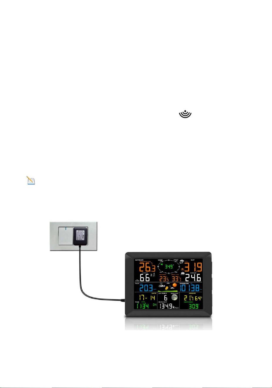
Note: The power adapter is intended to be correctly oriented in a
vertical or floor mounted position. The prongs are not designed to hold
the plug in place if it is plugged into a ceiling, under-the-table or cabinet
outlet.
Figure 12

13
Note: If the power adapter is plugged in, BL ON will display in the
time area for three seconds when powered up. Conversely, if the power
adapter is not plugged in, AC OFF will be displayed, the icon will
display .
3.4.3 Sensor Operation Verification
The following steps verify proper operation of the sensors prior to
installing the sensor array.
1. Verify proper operation of the rain gauge. Tip the sensor array back
and forth several times. You should hear a “clicking”sound within the
rain gauge. Verify the rain reading on the display console is not reading
0.00. Each “click”represents 0.3mm of rainfall.
2. Verify proper operating of the wind speed. Rotate the wind cups
manually or with a constant speed fan. Verify the wind speed is not
reading 0.0.
3. Verify proper operation of the indoor and outdoor temperature. Verify
the indoor and outdoor temperature match closely with the console and
sensor array in the same location
(about 3m apart). The sensors should be within 2°C (the accuracy is
±1°C). Allow about 30 minutes for both sensors to stabilize.
4. Verify proper operation of the indoor and outdoor humidity. Verify the
indoor and outdoor humidity match closely with the console and sensor
array in the same location (about 3m apart). The sensors should be
within 10% (the accuracy is ± 5%). Allow about 30 minutes for both
sensors to stabilize.
4. Weather Station Installation
4.1 Pre Installation Check. Before installing your weather station
in the permanent location, we recommend operating the weather
station for one week in a temporary location with easy access. This
will allow you to check out all of the functions, insure proper operation,
and familiarize you with the weather station and calibration procedures.
This will also allow you to test the wireless range of the weather station.
4.2 Location Survey
Perform a site survey before installing the weather station. Consider the
following:
1. You must clean the rain gauge once per year and change the
batteries every two years. Provide easy access to the weather station.

14
2. Avoid radiant heat transfer from buildings and structures. In general,
install the sensor array at least 5’ from any building, structure, ground,
or roof top.
3. Avoid wind and rain obstructions. The rule of thumb is to install the
sensor array at least four times the distance of the height of the tallest
obstruction. For example, if the building is 6m tall, install 4 x 6m = 24m
away. Use common sense. If the weather station is installed next to a
tall building, the wind and rain will not be accurate.
4. Wireless Range. The radio communication between receiver and
transmitter in an open field can reach a distance of up to 100 m,
providing there are no interfering obstacles such as buildings, trees,
vehicles, high voltage lines. Wireless signals will not penetrate metal
buildings. Most applications will only reach 30m due to building
obstructions, walls and interference.
5. Radio interference such as PCs, radios or TV sets can, in the worst
case, entirely cut off radio communication. Please take this into
consideration when choosing console or mounting locations.
4.3 Best Practices for Wireless Communication
Wireless communication is susceptible to interference, distance, walls
and metal barriers. We recommend the following best practices for
trouble free wireless communication.
1. Electro-Magnetic Interference (EMI). Keep the console several feet
away from computer monitors and TVs.
2. Radio Frequency Interference (RFI). If you have other 433 MHz
devices and communication is intermittent, try turning off these other
devices for troubleshooting purposes. You may need to relocate the
transmitters or receivers to avoid intermittent communication.
3. Line of Sight Rating. This device is rated at 100 m line of sight (no
interference, barriers or walls) but typically you will get 30 m maximum
under most real-world installations, which include passing through
barriers or walls.
4. Metal Barriers. Radio frequency will not pass through metal barriers
such as aluminum siding. If you have metal siding, align the remote and
console through a window to get a clear line of sight.
The following is a table of reception loss vs. the transmission medium.
Each “wall”or obstruction decreases the transmission range by the
factor shown below.
15
5. Final Installation of Sensors
Integrated outdoor transmitter installation.
Professional Wireless Weather Station can be used in both the
Northern and Southern Hemispheres.
Prior to installation, you will need to calibrate the wind direction.
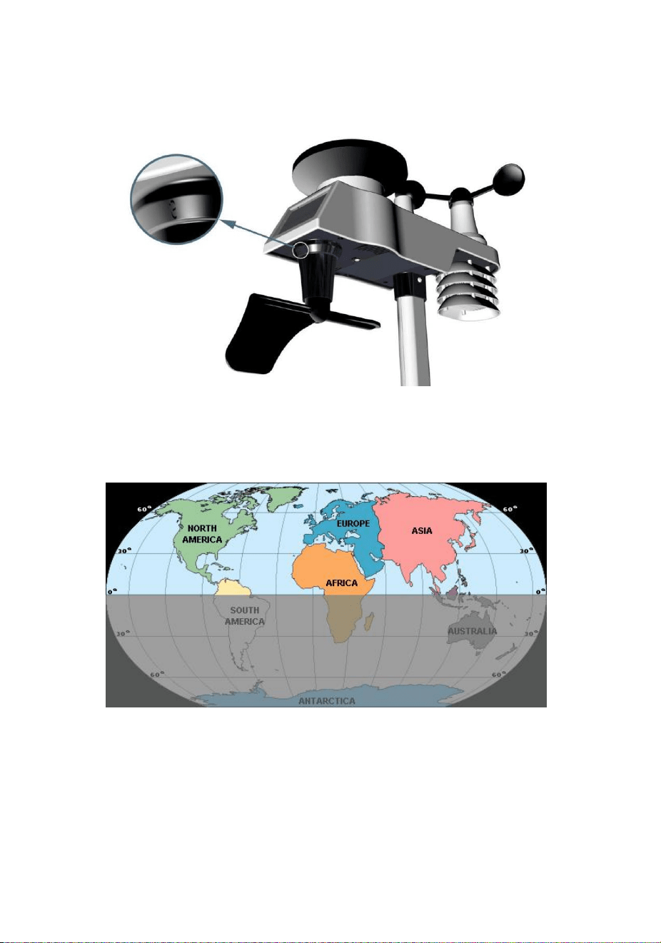
5.1. Northern Hemispheres (NOR).
The cardinal directions (N, S, E, W) molded on the body of the outdoor
sensor are indicators for the Northern Hemisphere only.
Step 1:There is a “S” indicator on the wind vane that indicates South,
as shown in Figure 13. Align this “S” marker in the direction of South.
Step 2: Console operation is set to Northern Hemispheres ( NOR in
the time area) in Location division.
Note: There are four alphabet letter of “N”,”E”,”S”and “W” around
the wind direction, representing for the direction of North, East, South
and West. Wind direction sensor has to be adjusted so that the
directions on the sensor are matching with your real location.
Medium
RF Signal Strength Reduction
Glass (untreated)
5-15%
Plastics
10-15%
Wood
10-40%
Brick
10-40%
Concrete
40-80%
Metal
90-100%
16
Permanent wind direction error will be introduced when the wind
direction sensor is not positioned correctly during installation.
Northern Hemispheres
Southern Hemispheres
Figure 13
17
5.2. Southern Hemispheres (SOU).
For Southern Hemisphere installations, ignore these(N, S, E, W) and
face the solar panel to the North (and in a sunny position) when
installing the Integrated outdoor transmitter.
Step 1: Install the Integrated outdoor transmitter and face the solar
panel North.
Step 2: Console operation is set to Southern Hemispheres ( SOU in the
time area) in Location division.
Note: Console has to be location division setting so that the
directions on the sensor are matching with your real location.
Permanent wind direction error(read approximately 180º)will be
introduced when the wind direction sensor is not positioned correctly
during installation.
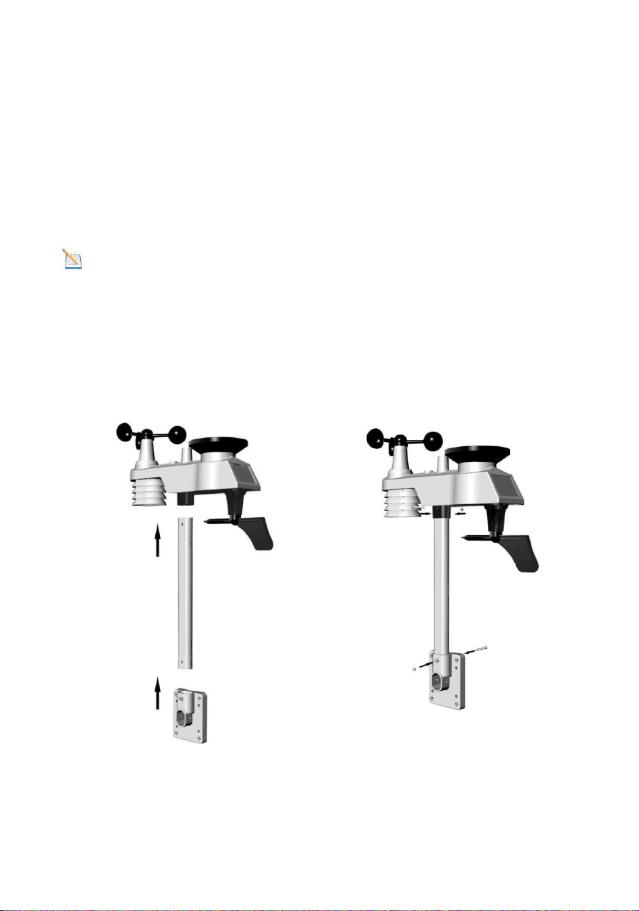
Fasten the integrated transmitter to mounting pole brackets with foot-
mounting, two ¢3 bolts and M3 nuts , as shown in Figure 14
Figure 14
18
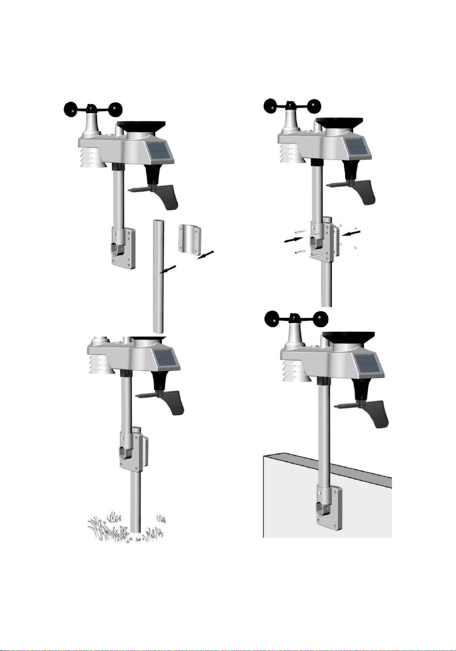
Tighten the mounting pole to your existing mounting pole with the four¢
5 Bolts and M5 Nuts assembly, or fix on the wall with four tapping screw,
as shown in Figure15.
Figure 15
19
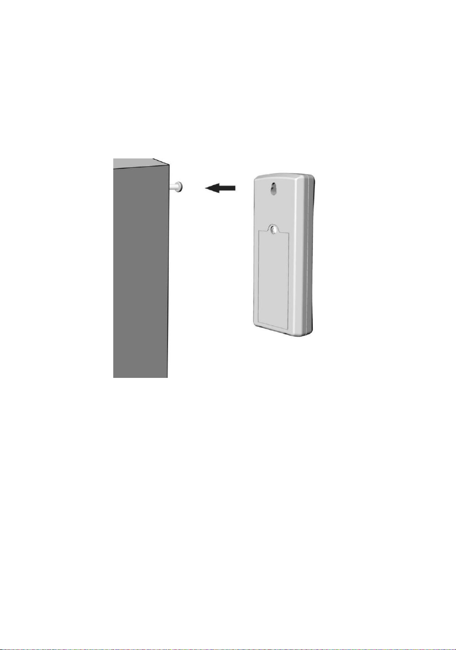
Thermo-hygrometer Transmitter installation. It is recommended you
mount the Thermo-hygrometer sensor outside in a shaded area. A north
facing wall is preferred because it is in the shade most of the day. Direct
sunlight and radiant heat sources will result in inaccurate temperature
readings. Although the sensor is water resistant, it is best to mount in a
well protected area, such as under an eve. Use a screw or nail (not
included) to affix the remote sensor to the wall, as shown in Figure 16.
Figure 16
6.Low Battery Icon
A low battery indicator icon is shown in the display window for thermo-
hygrometer sensor. When the low battery icon appears (the battery
voltage is lower than 2.4V), replace the batteries in the sensor with
fresh batteries. Be sure to never mix old and new batteries, and never
mix battery types such as alkaline and lithium together.
A low battery indicator icon is shown in the display window for
Integrated outdoor transmitter. When the low battery icon appears (the
battery voltage is lower than 3.6V), replace the batteries in the sensor
with fresh batteries. Be sure to never mix old and new batteries, and
never mix battery types such as alkaline and lithium together.

20
7. Console Operation
Note: The console has five keys for easy operation: MIN/MAX/-key,
ALARM key, SET/MODE key, CHANNEL/+ and SNOOZE key.
7.1 Quick Display Mode
Note: To exit the Quick Display Mode at any time, press the
SNOOZE key of the display console.
While in Normal Mode, press (do not hold) the SET/MODE key to enter
the Quick Display Mode as follows:
once for time, time/week and date,
twice for indoor temperature, dew point,
three for rainfall.
four for outdoor dew point temperature
Five for wind average
Six for pressure
Seven for sensor dew point
1.Time, Time/Week and Date. Press the CHANNEL/+ or MIN/MAX/-
key to toggle between time, time/week and date.
2.Indoor Temperature. Press the CHANNEL/+ or MIN/MAX/- key to
toggle between temperature and dew point
3.Rainfall. Press the CHANNEL/+ or MIN/MAX/- key to toggle between
rate, 24h, week, month and total.
To clear the total rain, press the CHANNEL/+ or MIN/MAX/- button
until total rain is displayed. The total rain will flash. Press and hold the
SET button for five seconds until total rain reads 0.0.
4.Outdoor Dew Point. Press the CHANNEL/+ or MIN/MAX/- key to
toggle between AT (Apparent Temperature) and dew point.
5.Wind Average. Press the CHANNEL/+ or MIN/MAX/- key to toggle
between current,2mins and 10 minutes.
6.Absolute Pressure and Relative Pressure. Press the CHANNEL/+
or MIN/MAX/- key to toggle between absolute pressure and relative
pressure.
7.Sensor Heat Index. Press the CHANNEL/+ or MIN/MAX/- key to
toggle between sensor heat index and dew point.

21
7.2 Set (Program) Mode
While in Normal Mode, press and hold the SET(MODE) key for at least
three seconds to enter the Set Mode. The first setting will begin flashing.
You can press the SET(MODE) key again to skip any step, as defined
below.
Note: In the Set mode, press the [+] key or [-] key to change or
scroll the value. Hold the [+] key or [-] key for three seconds to
increase/decrease rapidly.
Note: To exit the Set mode at any time, press the SNOOZE button
of the display console.
1. Time SYNC(default: ON).Press the SET key again to set the
network time sync. Press the [+] key or [-] key to switch between
SYNC time ON and SYNC time OFF of measure.
2. 12/24 Hour Format (default: 24h):.Press the SET(MODE) key
again to adjust the 12/24 hour format setting (FMT). Press the [+]
key or [-] key to change between 12 hour and 24 hour format.
3. Change Hour. press the SET(MODE) key again to set the hour.
Press the [+] key or [-]key to adjust the hour up or down. Note the
PM icon is present during afternoon hours.
4. Change Minute. Press the SET(MODE) key again to set the minute.
Press the [+] key or [-] key to adjust the minute up or down.
5. Date Format (default: MM-DD): Press the SET(MODE) key again
to enter the day/month format mode. Press the [+] key to switch
between MM-DD-YY, DD-MM-YY.
6. Change Month. Press the SET(MODE) key again to set the
calendar month. Press the [+] key or [-] key to adjust the calendar
month.
7. Change Day. Press the SET(MODE) key again to set the calendar
day. Press the [+] key or [-] key to adjust the calendar day.
8. Change Year. Press the SET(MODE) key again to set the calendar
year. Press the [+] key or [-] key to adjust the calendar year.
9. Max/Min Clearing (default: ON). Press the SET(MODE) key again
to set the max/min clearing mode (CLR). The Max/Min can be
programmed to clear daily (at midnight) or manually. Press the [+]
key or [-] key to switch between “Clears 24h” and Clears Manually.
10. Temperature Units of Measure (default: °C):. Press the
SET(MODE) key again to change the temperature units of measure
(the UNITSET icon will be displayed). Press the [+] key or [-] key to
switch between °F and °C units of measure.

22
11. Wind Speed Units of Measure (default: m/s). Press the
SET(MODE) key again to change the wind speed units of measure .
Press the [+] key or [-] key to toggle the wind speed units between
m/s, km/h, mph, knots or bft.
12. Rainfall Units of Measure (default: mm). Press the SET(MODE)
key again to change the Rainfall units of measure. Press[+] key or [-]
key to toggle the rainfall units between mm and inch.
13. Barometric Pressure Display Units(default: hPa). Press the
SET(MODE) key again to change the pressure units of measure.
Press the [+] key or [-] key to toggle the pressure units between
mmhg, inHg or hPa.
14. Pressure Threshold Setting (default level 2). Press the
SET(MODE) key again to change the pressure threshold. Press the
[+] key or [-] key to change pressure threshold 2 mbar/hour to 4
mbar/hour.(For detailed information of this part please refer to 15.5)
15. Weather Icons Setting (default: partly cloudy). Press the
SET(MODE) key again to change the initial weather icon. Press the
[+] key or [-] key to select the initial weather icon of Sunny, Cloudy,
Partly Cloudy or Rainy. (For detailed information of this part please
refer to 15.1 and 15.2)
16. Sunlight Display Units(default: W/㎡). Press the SET(MODE) key
again to change the sunlight units of measure. Press the [+] key or
[-] key to toggle the sunlight units between , W/㎡, fc or lux.
17. Location division.(default: Northern Hemisphere).Press the
SET(MODE) key again to change the location division. Press the [+]
key or [-] key to toggle the sunlight units Northern Hemisphere
(NOR)or Southern Hemisphere(SOU). (refer to 5.0 Final Installation
of Integrated outdoor transmitter)
7.3 Chanel Selection
Press the CHANNEL/+ button to switch the display between remote
thermo-hygrometer sensors 1 through 8, and scroll mode . In scroll
mode, all of the detected thermo-hygrometer sensors will be displayed
in five second intervals.
7.4 Sensor Search Mode
If a sensor loses communication, dashes (--.-) will be displayed. If a
specific channel is lost, press the CH/+ button to display that channel
prior to entering the search mode.

23
To reacquire the lost signal, press and hold the CH/+ button for 3
seconds to enter the sensor search mode.
The icon AIO will appear in the time area. You can synchronize one or
all of individual sensors. press the [+] or [-] key to toggle between the
following sensors:
AIO. Synchronizes Integrated outdoor transmitter
CH*. Synchronizes Channel 1-8 Sensors (dependent on which
channel is displayed before entering the Sensor Search Mode).
ALL. Synchronizes All Sensors.
NOT. Do nothing and exit the Sensor Search Mode.
After selecting one of the above options, press the SET(MODE) key to
resync, and the display will return to normal mode. Do not press any
buttons until the synchronization is complete. The remote search icon
will display constantly for 3 minutes until the signal is reacquired.
7.5 Reset Min/Max record
Note: If you own more than one thermo-hygrometer sensor, the
minimum and maximum value of all channels will be cleared in the reset
mode.
In normal mode, press (do not hold) the MIN/MAX/-key, the MAX icon
will be displayed in date area. Press the SET/MODE key to view max
values of rainfall (rate, 24h, week or month) , pressure (ABS or
REL),outdoor temperature and humidity((AT or dew point),indoor
temperature and humidity (temp or dew point) and sensor temperature
and humidity, sensor dew point or heat index.
Press the MIN/MAX/- key for three seconds to clear all max values. (
the rainfall, wind speed, wind gust, pressure, temperature and humidity
maximum values. The maximum values will now display the current
values).
Press the CHANNEL/+ button to switch the display between remote
thermo-hygrometer sensors 1 through 8 to view Max values.

24
Press the MIN/MAX/- key again (do not hold), the MIN icon will be
displayed. Press the SET/MODE key to view min values of pressure
(ABS or REL), outdoor temperature/humidity(AT or dew point),indoor
temperature/humidity(temp or dew point), sensor temperature humidity,
sensor dew point(dew point or heat index).
Press the MIN/MAX/- key for three seconds to clear all min values.(the
pressure, temperature and humidity minimum values. The minimum
values will now display the current values).
Press the CHANNEL/+ button to switch the display between remote
thermo-hygrometer sensors 1 through 8 to view Min values.
Press the SNOOZE key to exit the min/max checking and cleaning
mode, return to normal display mode.
7.6 Snooze Mode
If the alarm sounds, and you wish to silence the alarm, press the
SNOOZE key, the backlight will turn on. The alarm icon will continue to
flash and the alarm will silence for five minute. press any key
(MIN/MAX/+ SET/MODE, ALARM,CHANNEL/+) to permanently exit
the Snooze mode.
7.7 Back light Mode
If the LED is off, Press the SNOOZE button once. The backlight will turn
on for five seconds, and if no operation is performed for three seconds,
the backlight will turn off.
The backlight operation is different when operating on batteries to save
power.
ADJUSTABLE BACKLIGHT BRIGHTNESS
There are 3 levels of brightness of backlight. When the backlight is on
press SNOOZE key to switch between the 3 levels.
When backlight is off, press and hold the SNOOZE key for two seconds,
the backlight will turn on permanently, and BL ON icon will be displayed
for three seconds in the date area.
To turn off the backlight at any time press and hold the SNOOZE key
for two seconds. BL OFF icon will be displayed for three seconds in the
date field.

25
Note: If plugged into AC power, the time area will display AC ON
and the backlight will remain on. It is not recommended leaving the
backlight on for a long period of time when operating on batteries only,
or the batteries will run down quickly.
8. Alarm Mode
The FT0300 includes the following alarms:
Time (There are two alarms for time. Alarm 1 and Alarm 2)
Outdoor Temperature
Outdoor Humidity
Outdoor AT(Apparent Temperature)
Outdoor Dew Point
Outdoor Feels Like Temperature
Outdoor Dew Point
Wind Gust
Wind Average
Rate Rainfall
24 Hour Rainfall
Absolute Pressure
Relative Pressure
Indoor Temperature
Indoor Humidity
Indoor Dew Point
UV Index
Sunlight
Sensor(CH1) Temperature
Sensor(CH1) Humidity
Sensor(CH1) Heat Index
Sensor(CH1) Dew Point
8.1 Alarm Operation
When an alarm condition is exceeded, the alarm icon will flash
(visual) and the alarm beeper will sound (audible). To silence the
beeper, press any key.

26
8.2 Viewing the High and Low Alarms
To view the current alarm settings, press the ALARM key to enter the
alarm mode. HI AL 1 will be displayed in the date area. At the same
time Alarm 1 time and HI alarm parameters of indoor
temperature/humidity, outdoor temperature/humidity, rain rate, AT, feels
like, wind gust, wind average, absolute pressure, UV index, Sunlight,
Sensor(CH1) temperature/humidity and dew point are displayed. Press
SET/MODE key to view Alarm 2 time and HI alarm parameters of indoor
dew point, 24h rainfall, outdoor dew point, relative pressure and
Sensor(CH1) heat index.
Press ALARM key again to view the LOW alarms along with the alarm
clock time the same way HI alarms.
Press the SNOOZE key at any time to return to the normal mode.
8.3 Setting the Alarms
Press ALARM key to enter the alarm mode.
Press and hold the SET/MODE key for three seconds. The first alarm
parameter will begin flashing (alarm hour).
To save the alarm setting and proceed to the next alarm parameter,
Press (do not hold) the SET/MODE key.
To adjust the alarm parameter, press the [+] or [-] key to increase or
decrease the alarm settings, or press and hold the [+] or [-] key for
three seconds to increase or decrease the alarm settings rapidly.
Press the ALARM key to turn on (the alarm icon will appear ) and off
the alarm.
Press the SNOOZE key once at any time to return to the normal mode.
After 30 seconds of inactivity, the alarm mode will time out and return to
normal mode.
The following is a list of the individual alarm parameters that are set (in
order):

27
1. Alarm hour(alarm 1)
2. Alarm minute(alarm 1)
3. Alarm hour(alarm 2)
4. Alarm minute(alarm 2)
5. Outdoor temperature high alarm
6. Outdoor temperature low alarm
7. Outdoor humidity high alarm
8. Outdoor humidity low alarm
9. Outdoor AT high alarm
10. Outdoor AT low alarm
11. Outdoor dew point high alarm
12. Outdoor dew point low alarm
13. Outdoor feels like high alarm
14. Outdoor feels like low alarm
15. Wind Gust high alarm
16. Wind Average high alarm
17. Rainfall (RATE) high alarm
18. Rainfall (24h) high alarm
19. Absolute pressure high alarm
20. Absolute pressure low alarm
21. Relative pressure high alarm
22. Relative pressure low alarm
23. Indoor temperature high alarm
24. Indoor temperature low alarm
25. Indoor humidity high alarm
26. Indoor humidity low alarm
27. Indoor dew point high alarm
28. Indoor dew point low alarm
29. UV Index high alarm
30. Sunlight high alarm
31. Sensor(CH1) Temperature high alarm
32. Sensor(CH1) Temperature low alarm
33. Sensor(CH1) Humidity high alarm
34. Sensor(CH1) Humidity low alarm
35. Sensor(CH1) Heat Index high alarm
36. Sensor(CH1) Heat Index low alarm
37. Sensor(CH1) Dew Point high alarm
38. Sensor(CH1) Dew Point low alarm

28
Note: To prevent repetitive temperature alarming, there is a 0.5 °C
tolerance band. For example, if you set the high alarm to 26.7 °C and
silence the alarm, the alarm icon will continue to flash until the
temperature falls below 26.2°C, at which point, the alarm will reset and
must increase above 26.7 °C to activate again.
Note: To prevent repetitive alarming of humidity, there is a 4%
tolerance band in humidity alarm. For example, if you set the high alarm
to 60% and silence the alarm, the alarm icon will continue to flash until
the humidity falls below 56%, at which point, the alarm will reset and
must increase above 60% to activate again.
8.4 Alarm and Command Key Beeper ON/OFF Mode
The beeper can be silenced for both alarms and key strokes.
In normal mode, press and hold the ALARM key for three seconds to
toggle the beeper on or off (depending on the current setting).
The BZON (beeper on) or BZOFF (beeper off) icon will appear in the
time area for three seconds. press and hold the ALARM key again for
three seconds to toggle the BZON or BZOFF command.
9. WiFi Connection Status
When the console successfully connects to your Wi-Fi router, the Wi-Fi
signal icon will appear on the LCD display(behind the Outdoor
humidity). If the Wi-Fi signal is not stable or the console is trying to
connect to the router, the icon will flash. If the icon disappears, it means
the console is not connected to the Wi-Fi router.
Note: If you own a dual band router (2.4 GHz and 5.0
GHz),make sure you connect to the 2.4 GHz band, otherwise it will
fail to connect the weather station to WiFi.
10. Time Server Sync Status
After the console has connected to the internet, it will attempt to
connect to the internet time server to obtain the time. Once the
connection succeeds and the console’s time has updated, the SYNC
29
icon will appear on the LCD. The time will automatically
synchronize to the internet per an hour.
Note:Time synchronize method: Synchronized through internet
UTC time server.
WiFi Connection and Weather Servers
11. Register with WeatherCloud.net
Note: This is best done on a computer desktop or laptop.
Visit : https://weathercloud.net/ and enter a Username, Email and
Password(It is your Login password of the websiteIt, not your email
password. So no privacy will be exposed).
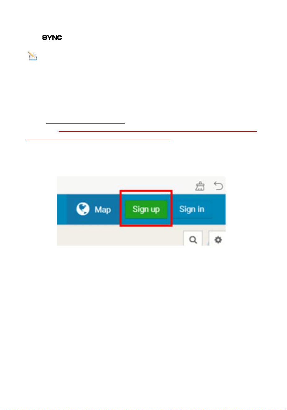
11.1 Sign Up
1) Click Sign up as below
Figure 17
2) As shown below, enter a Username, Email and Password then Click
Sign up.
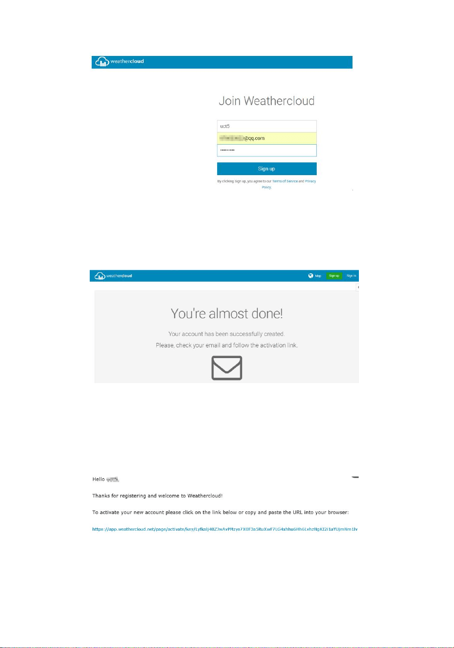
30
Figure 18
3) As shown below, an email will be received in your registered mailbox .
Figure 19
4) As shown below, open your mail and log in to the Web address in the
mail.
Figure 20
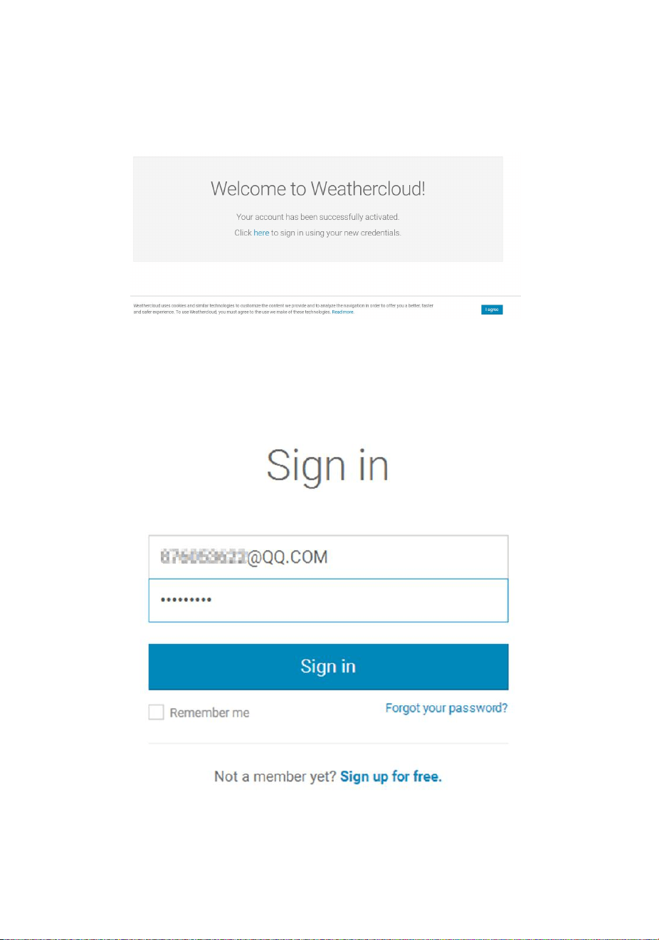
31
5) As shown below, click “here” to enter the homepage of the
weathercloud website.
Figure 21
6) As shown below, enter the email address and password you just
registered to enter the weathercloud website.
Figure 22
32
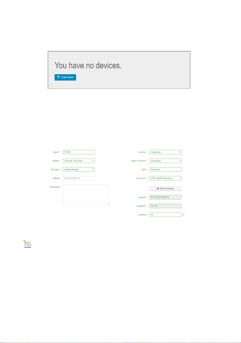
11.2 Add a weather station device (it may take a few
minutes).
Figure 23
1) After sign up you will be prompted to add a device/ Select “Create
device” and enter your station’s information: Blanks with red * must be
filled in.
Figure 24
Note: You can select any Model number and Link type in the
above blanks.
2) As shown below, click Get coordinates to identify your location of on
the map, then click Done to confirm..
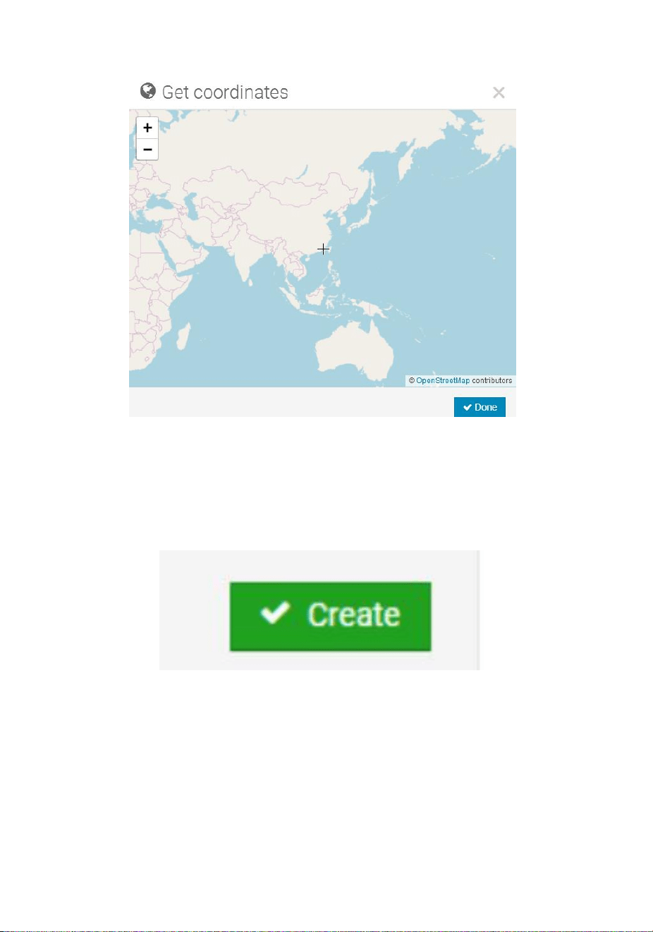
33
Figure 25
3) As shown below, click Create.
Figure 26
4) As shown below, after registering successfully, please record the
Weathercloud ID and Key information for later use. (Refer to 13.6)
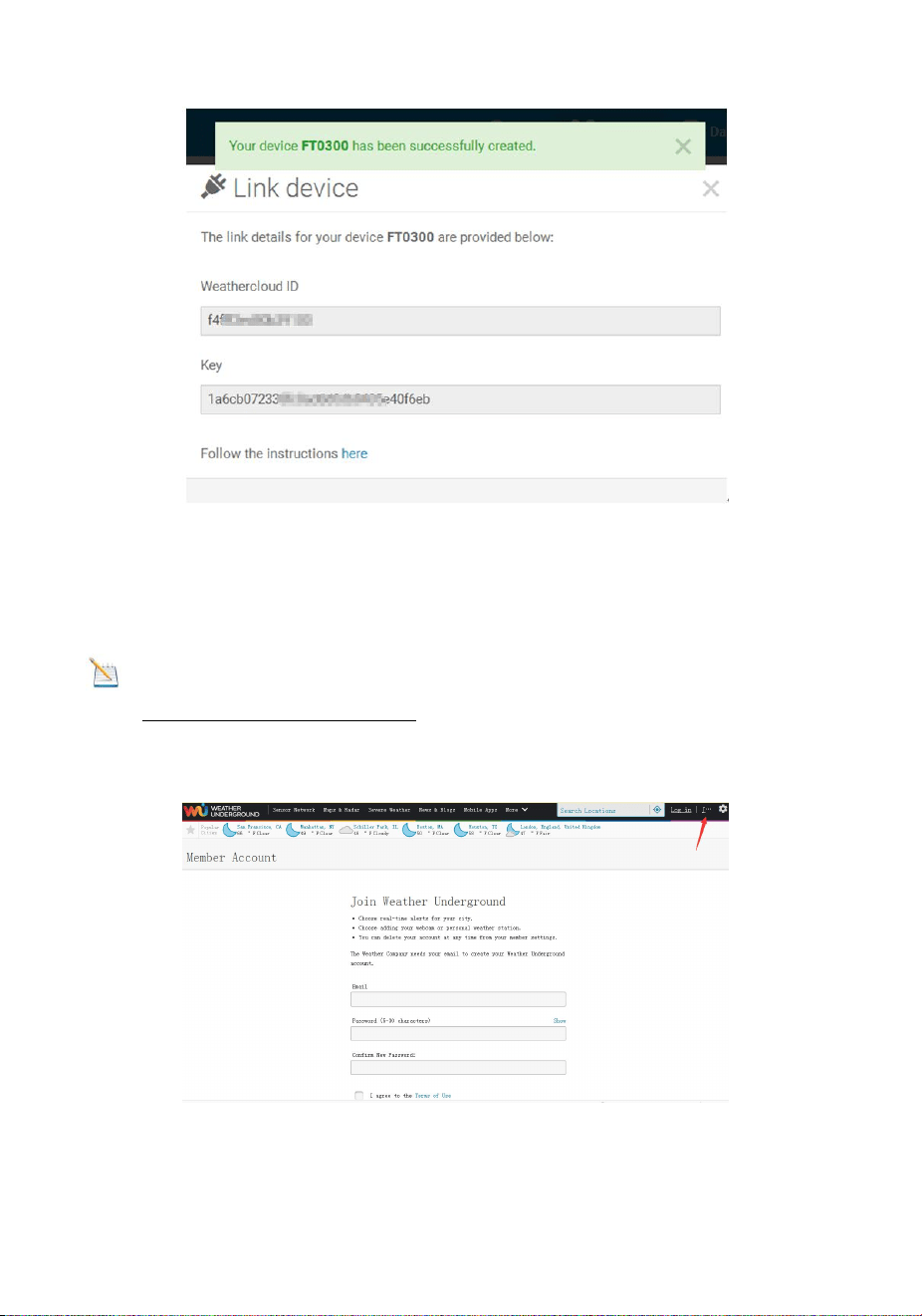
35
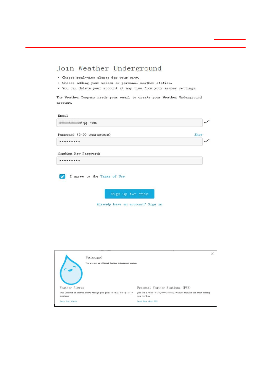
2) As shown below, enter a Username, Email and Password(It is your
Login password of the websiteIt, not your email password.So no
privacy will be exposed). Click Sign up for free.
Figure 29
3) As shown below, registration is done successfully.
Figure 30
4) As shown below, click Log in and enter the email address and
password you just registered.
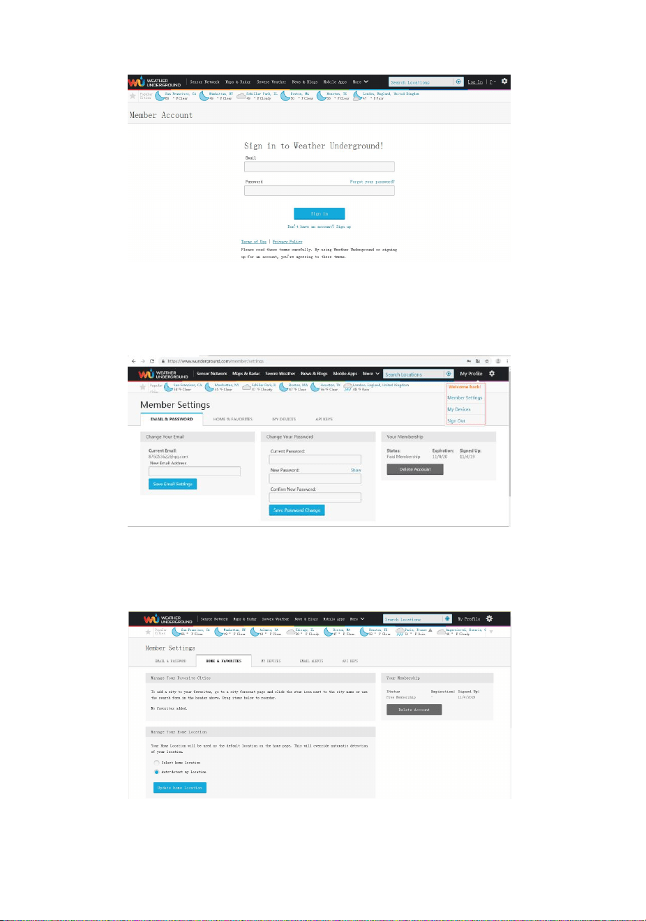
36
Figure 31
5) As shown in the below, click My Profile. Then enter Member Settings.
Figure 32
6) As shown below, click Update home location.
Figure 33
37
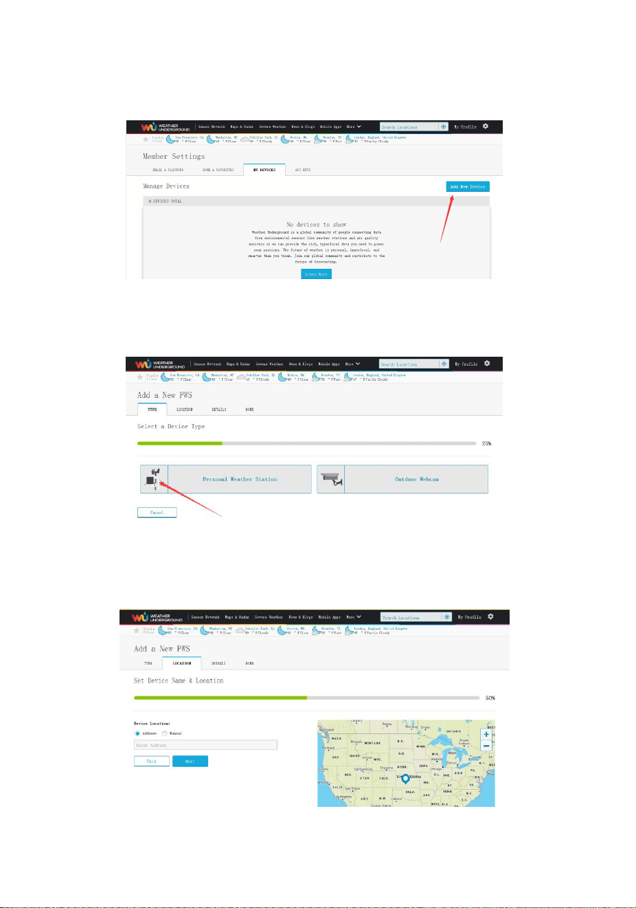
7) As shown below, you will then be prompted to add a device/ Select
“Add New Device
Figure 34
8) As shown below, click Personal Weather Station.
Figure 35
9) As shown below, select Address by inputting an address or select
Manual to position your address automatically. Then click Next:
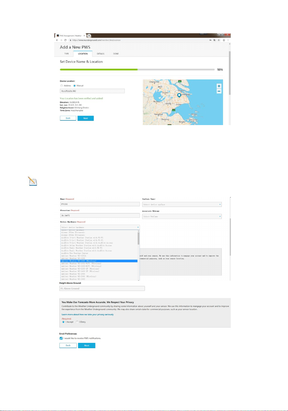
38
Figure 36
10) As shown below, you will then be prompted to add a device/ Select
“Create device” , then click I Accept and Next:Blanks with red (Required)
must be filled in.
Note: You can select any wifi weather station model in Device
Hardware blank.
Figure 37
39
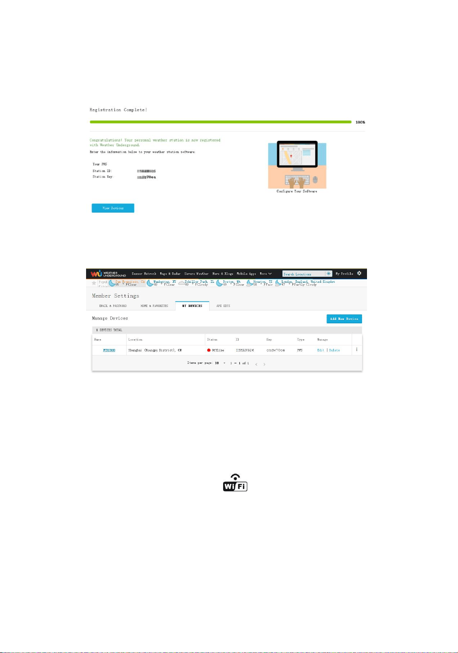
11) As shown below, after registering the host successfully, please
record Station ID and Station Key information for later use (refer to
13.6).
Figure 38
12) As shown below, registration is done successfully.
Figure 39
13.WiFi Setup(Connect your Device to the
Console’s WiFi)
When you first power up(AC) the console, or press and hold the
MIN/MAX/- button for three seconds in normal mode, the console
icon(behind the Outdoor humidity)) will flash to signify that it has
entered WAP (wireless access point) mode, and is ready to enter for
WIFI settings.
You can use your desktop, laptop, tablet, or smart phone to connect to
the console’s WiFi. The console’s network name begins with
WeatherHome, followed by a unique code.
40
Note: That when the console programming is complete, you
will resume your default WiFi connection.
Note: That you cannot connect two or more devices at the
same time when WAP mode.
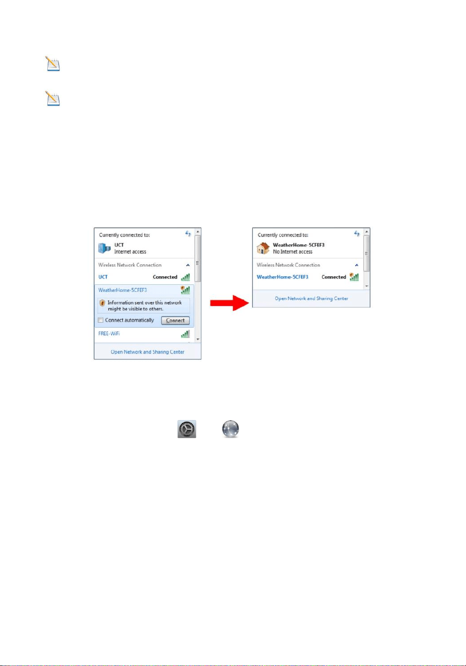
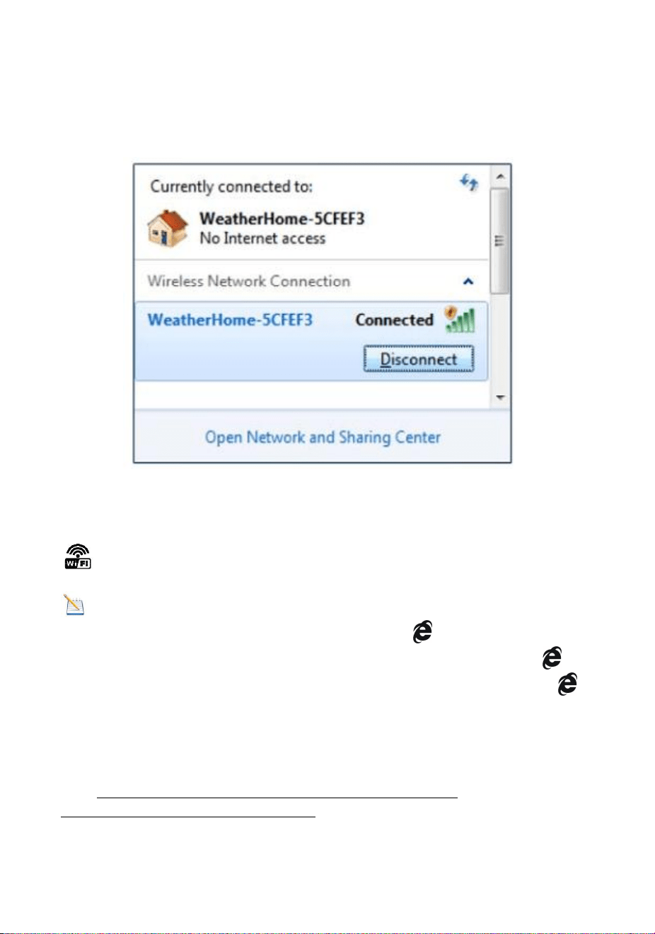
13.1:Example 1: Connect to the console WiFi server with a PC.
Choose WiFi network settings from Windows (or search “Change Wi-Fi
Settings” from Windows), and Connect to the WeatherHome WiFi
network, as shown in Figure 40 (your WiFi network name may be
slightly different, but will always begin with WeatherHome).
Figure 40
13.2: Example 2. Connect to the console WiFi server with a Mac.
Choose the Settings icon and Network . Connect to the
WeatherHome WiFi network, as shown in Figure 41 (your WiFi network
name may be slightly different, but will always begin with
WeatherHome).
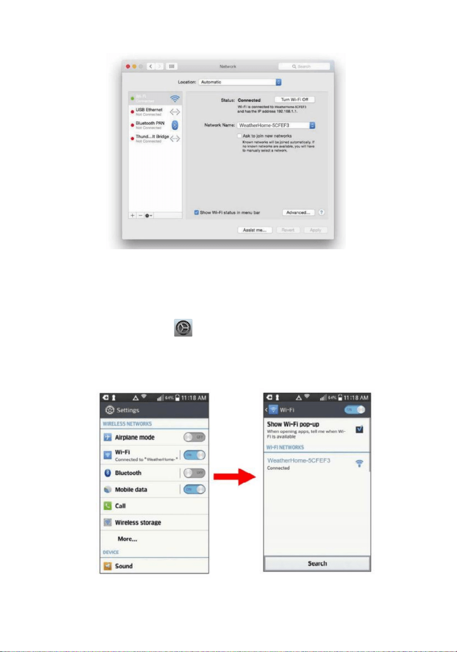
41
Figure 41
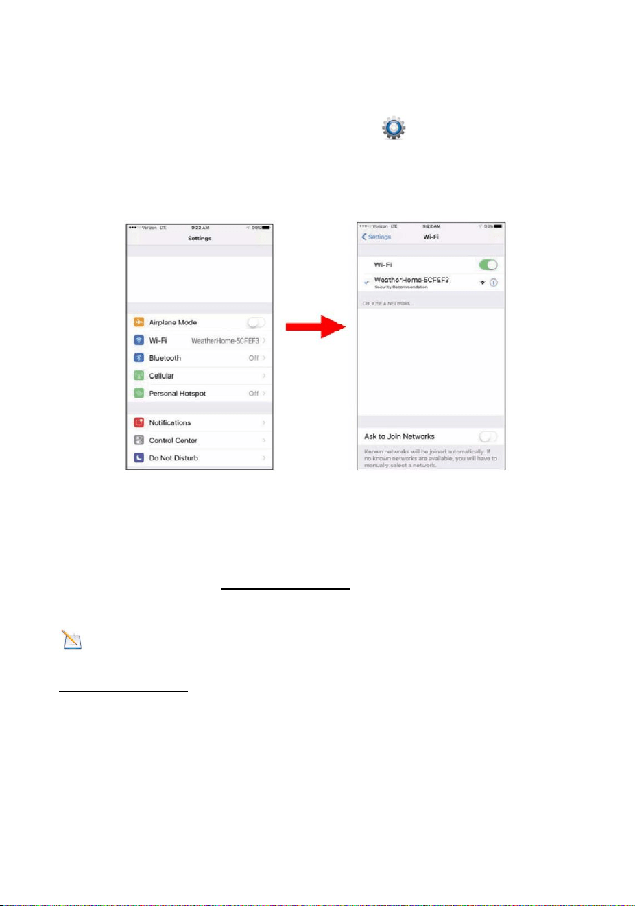
13.3: Example 3. Connect to the console WiFi server with an
iPhone or iPad.
Choose the Settings icon and Wi-Fi. Connect to the
WeatherHomeWiFi network, as shown in Figure 42 (your WiFi network
name may be slightly different, but will always begin with
WeatherHome).
Figure 42
42
13.4: Example 4. Connect to the console WiFi server with an
Android device.
From the Apps icon, choose the Settings icon and Wi-Fi. Connect to
the WeatherHome WiFi network, as shown in Figure 43 (your WiFi
network name may be slightly different, but will always begin with
WeatherHome).
Figure 43
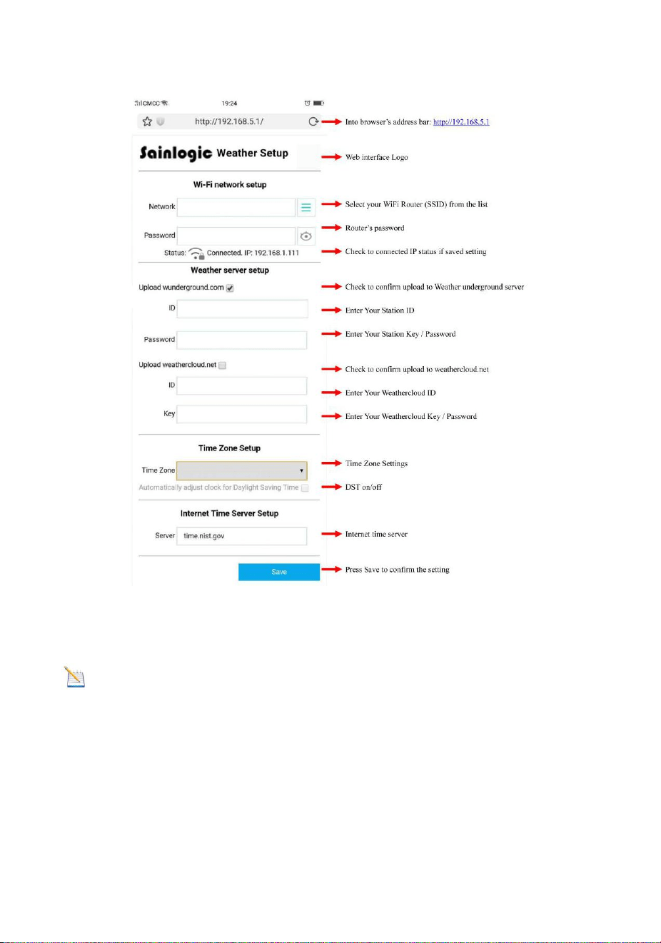
13.5. Once connected, enter the following IP address into any
browser’s address bar:http://192.168.5.1to access the console’s web
interface.
Note: Some browsers will treat 192.168.5.1 as a search, so
make sure you include the header http://,or:
http://192.168.5.1 not 192.168.5.1
13.6. Enter the following information into the web interface (Figure 44).
Make sure all of the information is entered prior to selecting Save. If you
choose not to upload Wunderground.com, or upload weathercloud.net,
leave the check boxes unchecked.
43
Figure 44
Notes: Hidden SSIDs. If you have a hidden SSID, enter the SSID
manually.
Time Zone Settings(default: 0h). based on the number of hours from
Coordinated Universal Time, or Greenwich Mean Time (GMT).
The following table provides times zones throughout the world.
Locations in the eastern hemisphere are positive, and locations in the
western hemisphere are negative.
44
Hours
from
GMT
Time Zone
Cities
-12
IDLW: International Date Line
West
---
-11
NT: Nome
Nome, AK
-10
AHST: Alaska-Hawaii Standard
CAT: Central Alaska
HST: Hawaii Standard
Honolulu, HI
-9
YST: Yukon Standard
Yukon Territory
-8
PST: Pacific Standard
Los Angeles, CA,
USA
-7
MST: Mountain Standard
Denver, CO, USA
-6
CST: Central Standard
Chicago, IL, USA
-5
EST: Eastern Standard
New York, NY, USA
-4
AST: Atlantic Standard
Caracas
-3
---
São Paulo, Brazil
-2
AT: Azores
Azores, Cape Verde
Islands
-1
WAT: West Africa
---
0
GMT: Greenwich Mean
WET: Western European
London, England
1
CET: Central European
Paris, France
45
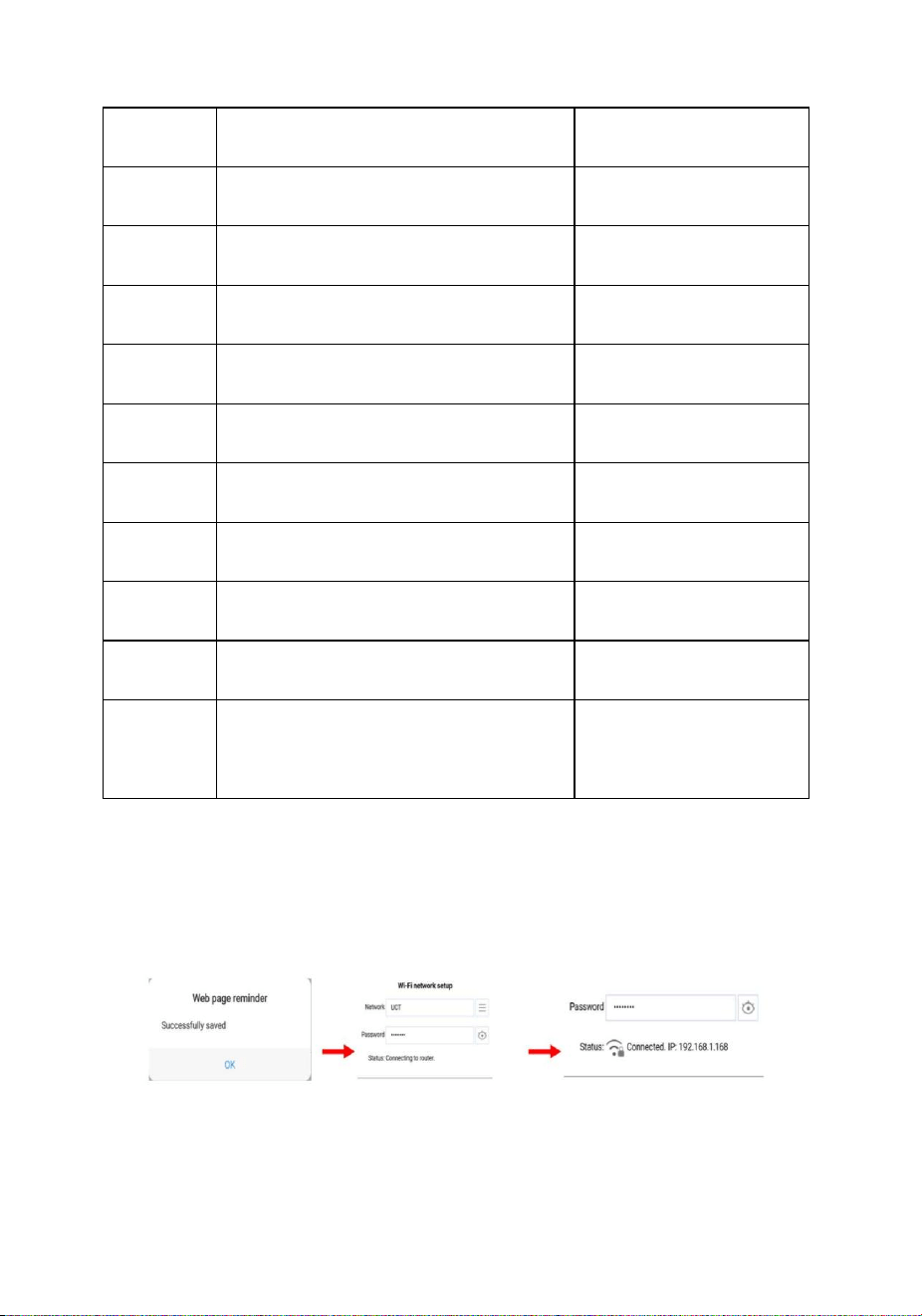
13.7. If all of the information you entered is correct press save to
confirm(Figure 45). If it does not, check your web interface information
again.
Figure 45
2
EET: Eastern European
Athens, Greece
3
BT: Baghdad
Moscow, Russia
4
---
Abu Dhabi, UAE
5
---
Tashkent
6
---
Astana
7
---
Bangkok
8
CCT: China Coast
Bejing
9
JST: Japan Standard
Tokyo
10
GST: Guam Standard
Sydney
11
---
Magadan
12
IDLE: International Date Line
East
NZST: New Zealand Standard
Wellington, New
Zealand
46
13.8. Once the setup is completed, disconnect your device from the
console WiFi. Otherwise,the console will automatically exit WAP mode.
(Figure 46)
Figure 46
If the connection is successful, the Wi-Fi console’s status Wi-Fi icon
will stop flashing and remain on.
NOTE: When the console successfully connects to your any
website of weather servers, the data signal icon will appear on the
LCD display (behind the Outdoor humidity). If the data signal icon is
flashing, the console is currently uploading to the server. If the icon
disappears, the console is not connected to the weather server for more
than 30 minutes.
13.9 Viewing your Data on Weather Underground
Visit:http://www.wunderground.com/personal-weather-
station/dashboard?ID=STATIONID
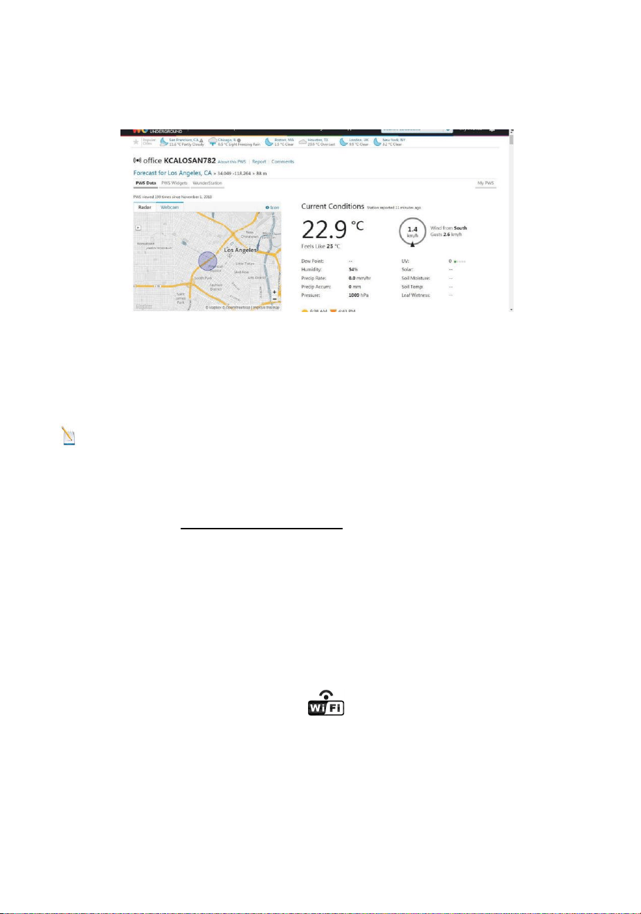
47
where STATIONID is your personal station ID (example,
KCALOSAN782).
Figure 47
Multiple Sensor Features
Wunderground.com does not support multiple sensor channels.
Note: The current temperature and humidity data is the Integrated
Outdoor Transmitter.
13.10. View your data on Weathercloud.
Visit the website www.weathercloud.net and sign in with your e-mail
address and password. Then you will go to the weather data of your
weather station automatically.
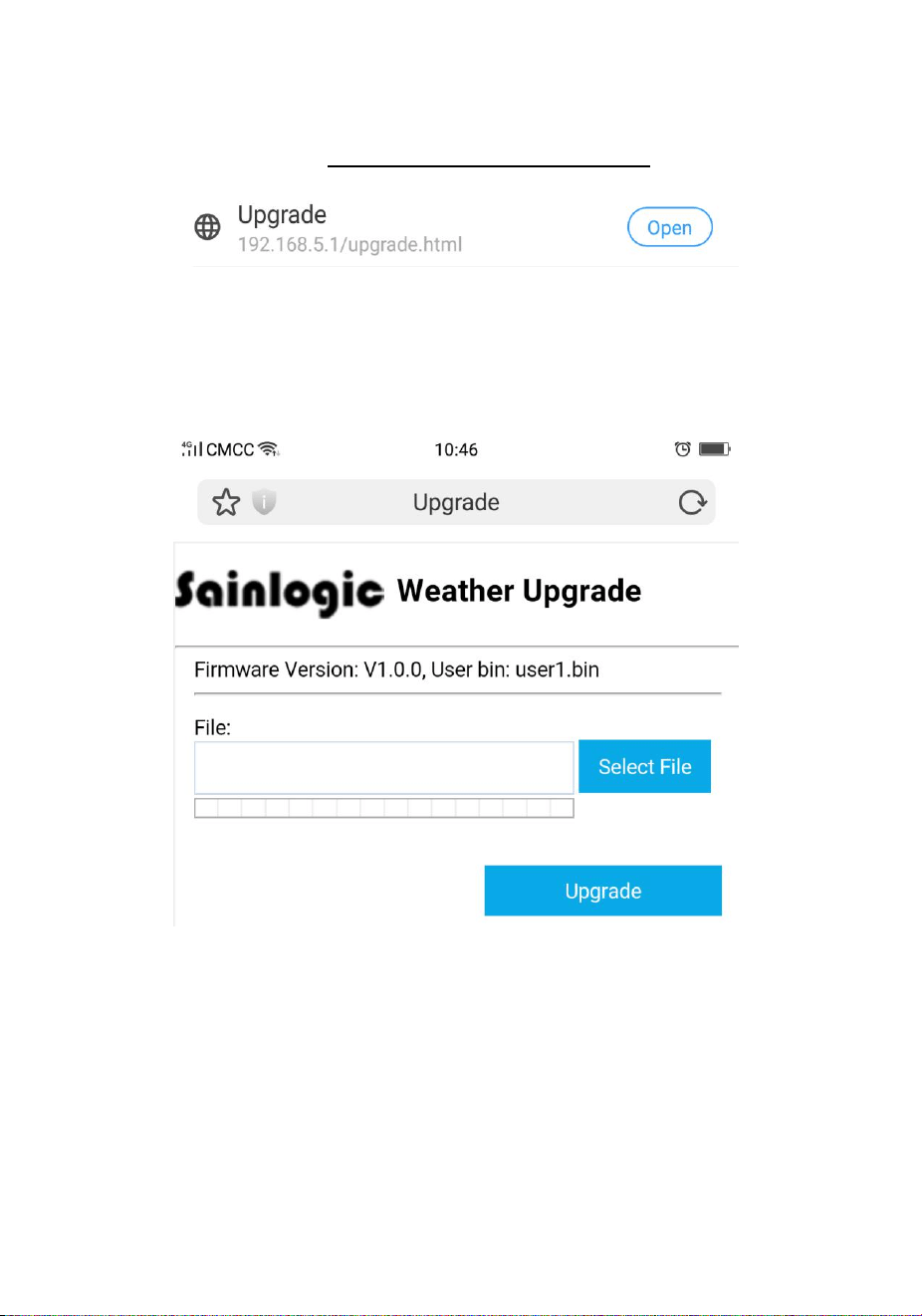
14. Upgrade firmware
You may get the latest firmware of the console as below
14.1. When you first power up(AC) the console, or press and hold the
MIN/MAX/-(WiFi) button for three seconds in normal mode, the console
icon(behind the Outdoor humidity) will flash to signify that it has
entered WAP (wireless access point) mode, and is ready to enter for
WIFI settings.
14.2. Use your smart phone, tablet, or computer to connect to the
console through WiFi(reference: Example 1-4 of WiFi Setting ).
49
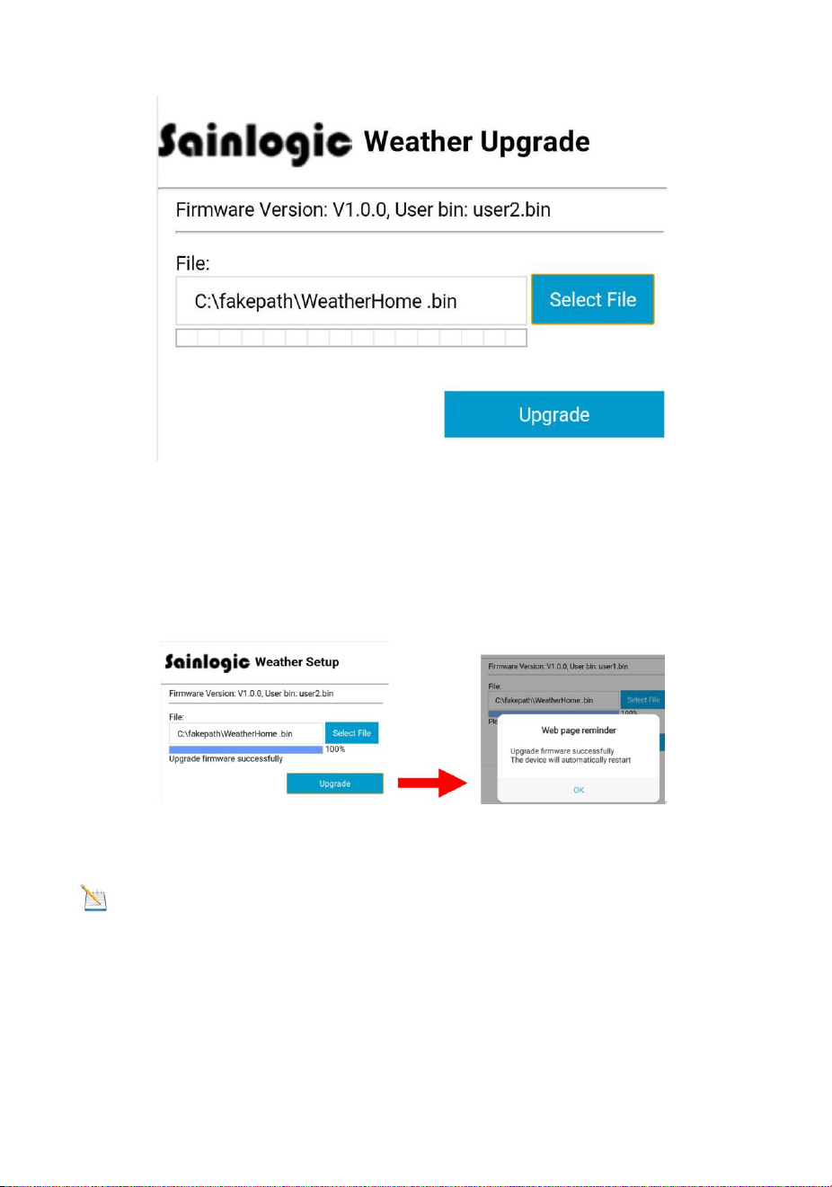
Figure 50
14.6. If update successfully when press Upgrade
key. Then you will see the following.
Figure 51
NOTE: In this upgrade only Wifi firmware is updated. The console
does not reset.
14.7.Once the upgrade is completed, the console will automatically
exit WAP mode.
50
15. Other Console Features
The following section describes additional features and display icons.
15.1 Weather Forecasting
Note: The weather forecast or pressure tendency is based on the
rate of change of barometric pressure. In general, when the pressure
increases, the weather improves (sunny to partly cloudy) and when the
pressure decreases, the weather degrades (cloudy to rain).
The weather forecast is an estimation or generalization of weather
changes in the next 24 to 48 hours, and varies from location to location.
The tendency is simply a tool for projecting weather conditions and is
never to be relied upon as an accurate method to predict the weather.
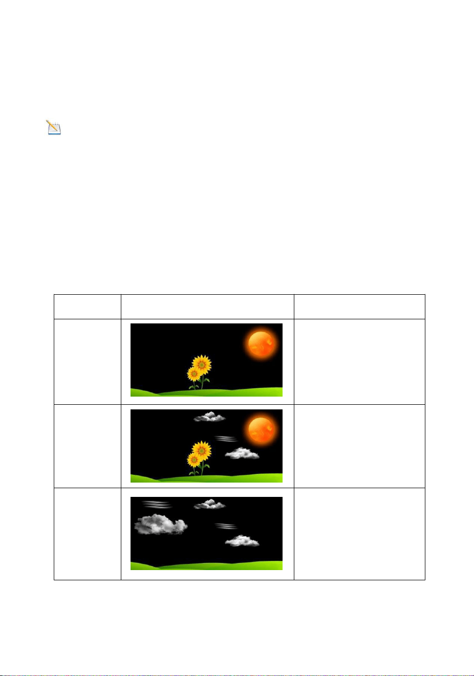
15.2 Weather Icons
Condition
Icon
Description
Sunny
Pressure is rising and
the previous condition
is partly cloudy.
Partly
Cloudy
Pressure is falling and
the previous condition
is sunny or Pressure is
rising and the previous
condition is cloudy.
Cloudy
Pressure is falling and
the previous condition
is partly cloudy or
pressure is rising and
the previous condition
is rainy.
51
Rainy
Pressure is falling and
the previous condition
is cloudy.
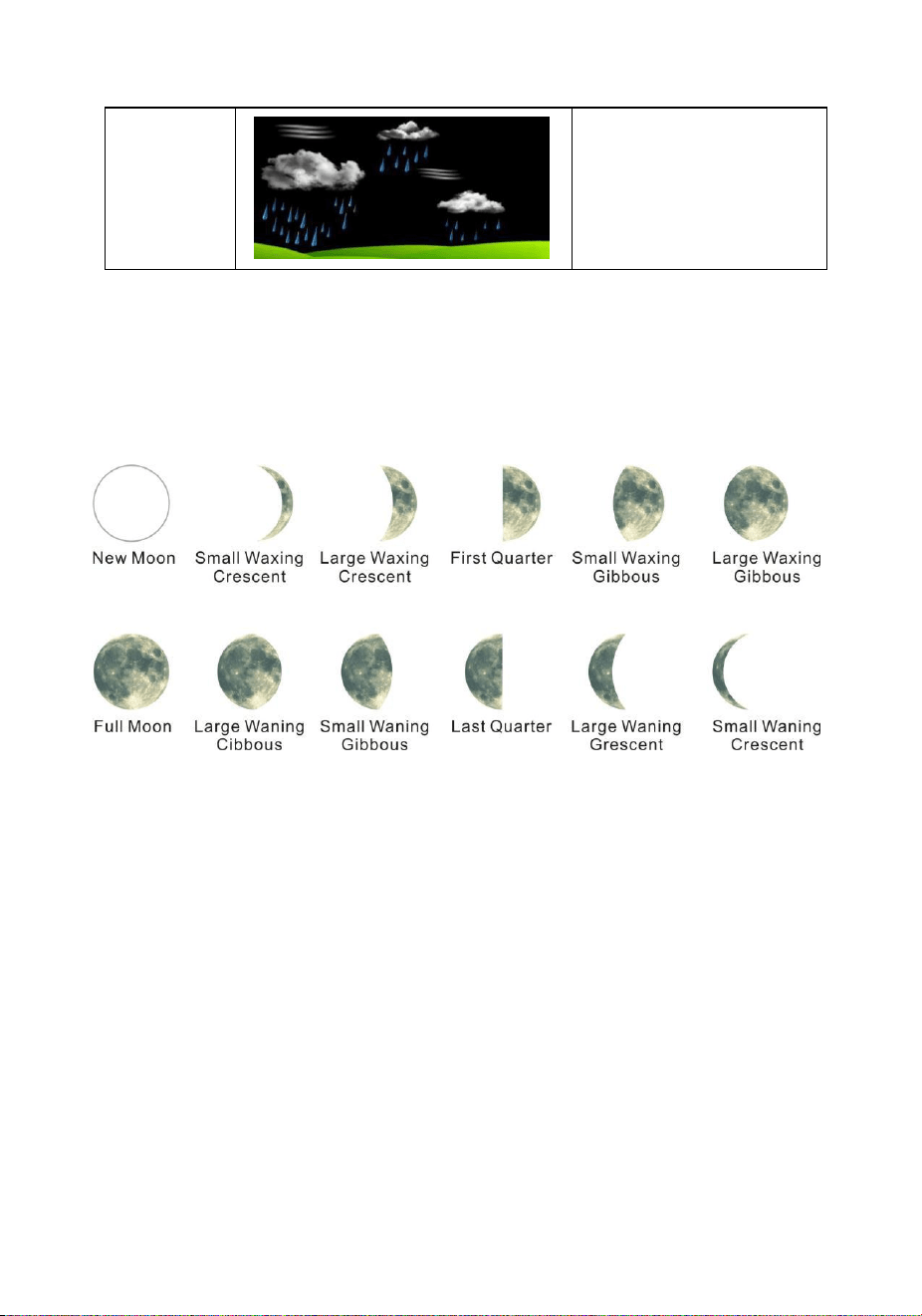
15.3 Moon Phase
The following moon phases are displayed based on the calendar date.
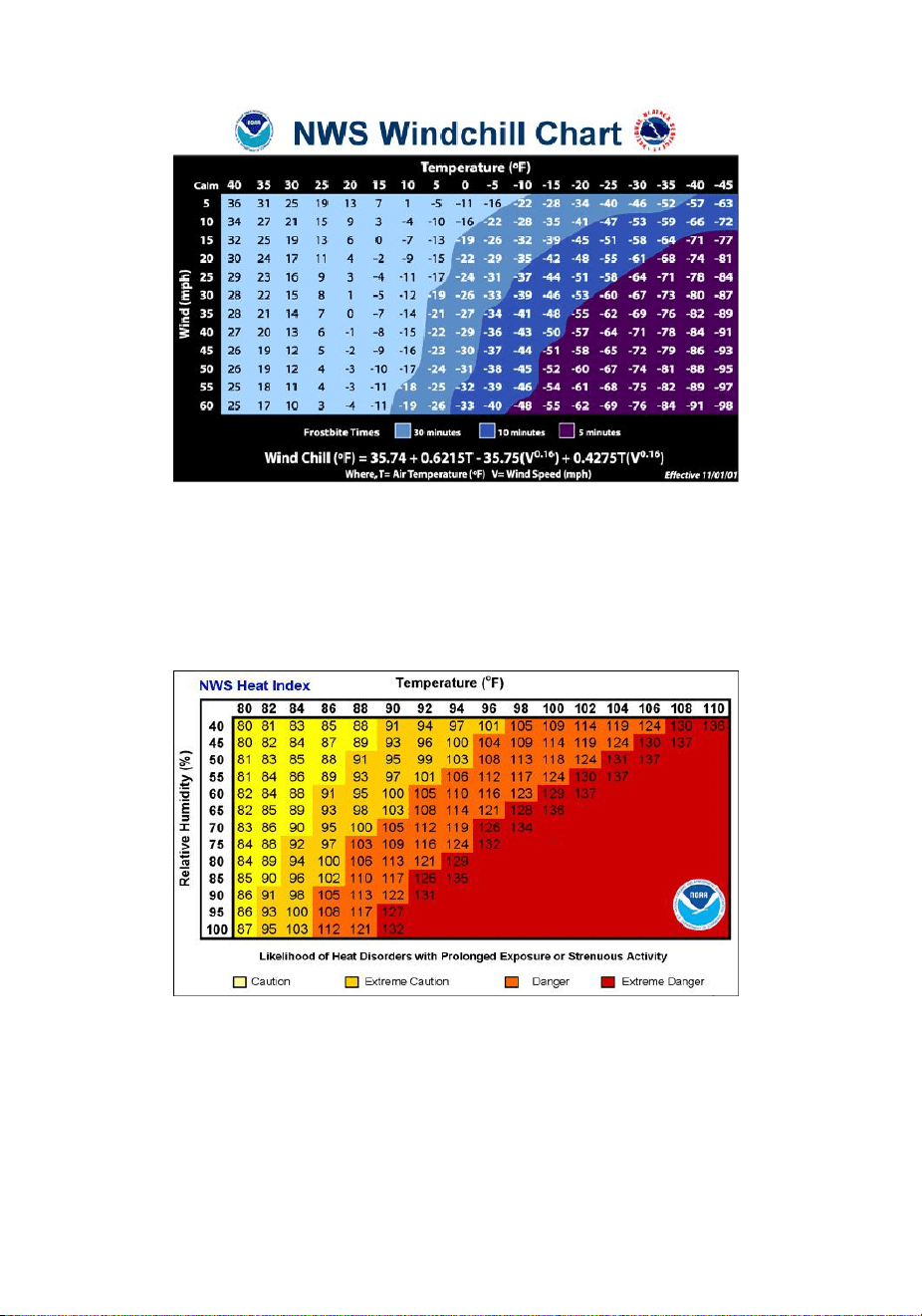
15.4 Feels Like Temperature and AT
Feels like temperature is a combination of Heat Index and Wind Chill.
At temperatures less than 4.4C(40°F), the wind chill is displayed, as
shown in the National Weather Service Wind Chill Table below:
52
Figure 52
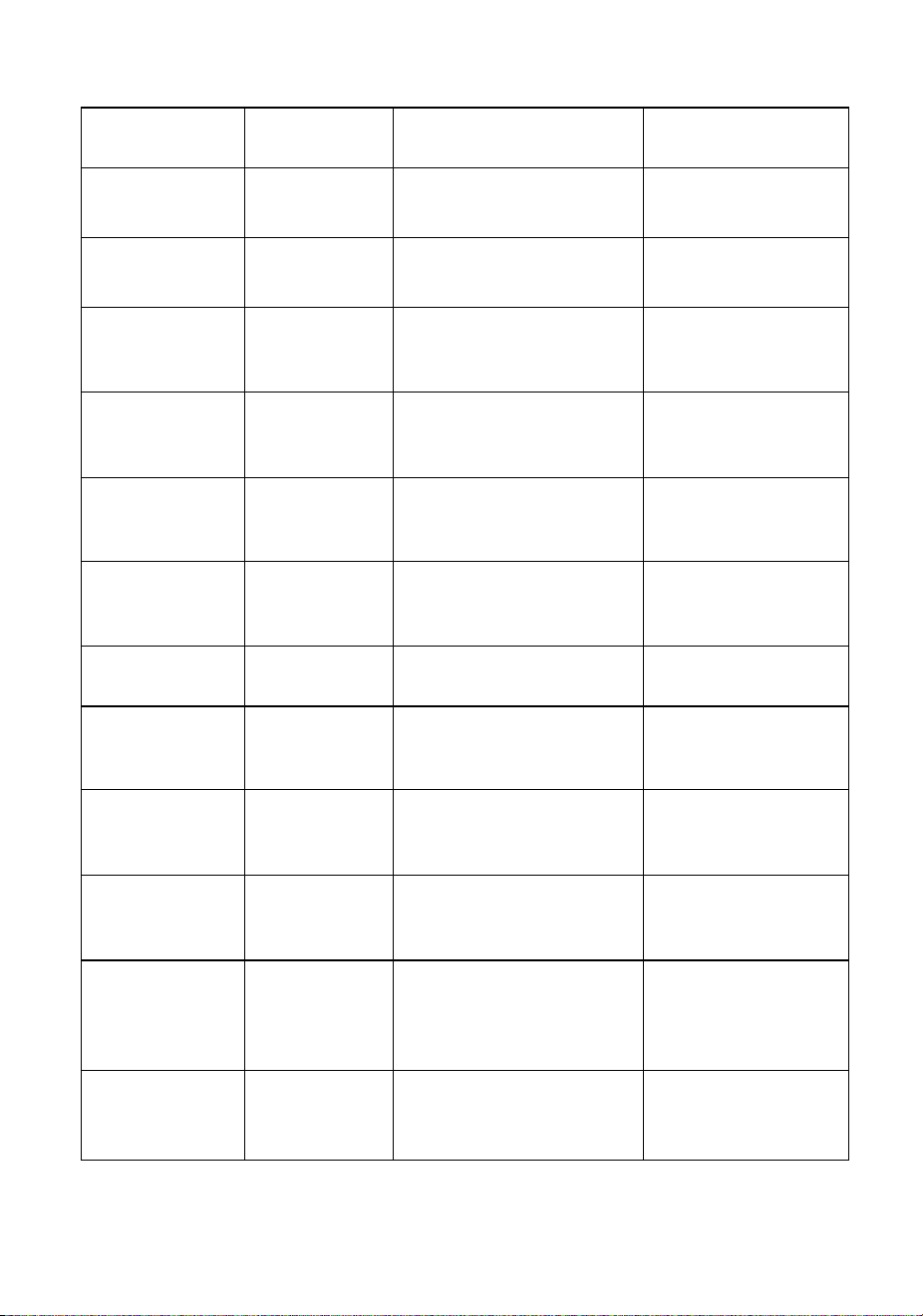
At temperatures greater than 26.7C(80°F), the heat index is displayed,
as shown in the National Weather Service Heat Index Table below:
Figure 53
When the temperature is between 4.4C (40°F) and 26.7C (80°F), the
OUT temperature is displayed (Feels Like temperature is the same as
OUT temperature).

53
The concept of apparent temperature (AT) is a linear regression that
is not restricted, and is more appropriate to outside conditions because
it includes wind. and was intended as an assessment of what exposed
body surfaces feel like in cold, windy conditions
Regression equations of this universal scale are formulated for indoors,
outdoors in shade but exposed to wind, and outdoors exposed to wind
and solar radiation. Of these, outdoors in shade but exposed to wind,
has been chosen as most informative.
15.5 Pressure Threshold Setting
The pressure threshold (the negative or positive rate of change of
pressure signifying a change in the weather) can be adjusted from 2
mbar/hour to 4 mbar/hour (default level 2 mbar/hour).
The lower the level pressure threshold setting, the higher sensitivity for
weather forecast changes. Locations that experience frequent changes
in air pressure require a higher setting compared to locations where the
air pressure is typically stagnant.
15.6 Restore Factory Default
To restore the console to factory default (WiFi network ,Weather server
and display), press the MIN/MAX/- key while installing the batteries at
the same time. Wait 3 seconds after installing the batteries to let go of
the MIN/MAX /- key.
16. Specifications
16.1 Wireless Specifications
Line of sight wireless transmission (in open air): 100m.
Frequency: 433 MHz
Thermo-hygrometer Transmitter update interval: 60 seconds
Integrated Outdoor transmitter interval: 16 seconds
16.2 Measurement Specifications
The following table provides specifications for the measured parameters.
54
Measurement
Range
Accuracy
Resolution
Indoor
Temperature
0 to 60 °C
± 1 °C
0.1 °C
Outdoor
Temperature
-40 to 60 °C
± 1 °C
0.1 °C
Indoor
Humidity
10 to 99 %
± 5% (only guaranteed
between 20 to 90%)
1 %
Outdoor
Humidity
10 to 99%
± 5% (only guaranteed
between 20 to 90%)
1 %
Sensors 1-8
Temperature
-40 to 60 °C
± 1 °C
0.1 °C
Sensors 1-8
Humidity
10 to 99%
± 5% (only guaranteed
between 20 to 90%)
1 %
UV Index
1 to 15+
± 1
± 1
Sunlight
0 to 200klux
± 15%
± 15%
Rain
0 to 9999mm
<15mm:±1 mm,
15mm to 9999mm:±7%
<1000mm (0.3mm)
>1000mm (1mm)
Wind Direction
0 - 360 º
± 10º (16 point
compass)
± 1º (16 point
compass)
Wind Speed
0 to 50 m/s
2 m/s ~10 m/s: ±3m/s,
10m/s ~50 m/s: ±10%
(whichever is greater)
0.1 m/s
Barometric
Pressure:
300 to 1100
hpa
± 3 hpa
0.1 hpa

55
16.3 Power Consumption
Base station (display console) : 3 x AAA 1.5V Alkaline or
Lithium batteries (not included)
Adaptor: 5.9V~ 500mA (included)
Thermo-hygrometer Sensor : 2 x AAA alkaline batteries or
Lithium batteries (not included
Integrated Outdoor Transmitter: 3xAA alkaline batteries or
Lithium batteries (not included)
Battery life: Minimum 12 months for base station with excellent
reception. Intermittent reception may reduce the battery life.
Minimum 12 months for Integrated Outdoor Transmitter (use
lithium batteries in cold weather climates less than -20 °C), The
primary power source is the solar panel. The batteries provide
backup power when there is limited solar energy
Minimum 12 months for sensors (use lithium batteries in cold
weather climates less than -20 °C)
16.4 WiFi Specifications
1. WIFI Standard: 802.11 b/g/n
2. WiFi Console RF Frequency: 2.4 GHz
3. Setup User Interface (UI) support setup device: Build-in WiFi with
WAP mode smart device, including laptops, computers, smart phones
and smart pads.
4. Recommend web browser for setup UI: Web browser support of
HTML 5, such as the latest versions of Chrome, Safari, IE, Edge,
Firefox or Opera.
5. Line of sight WiFi RF transmission (in open air): 20meter (80 feet)
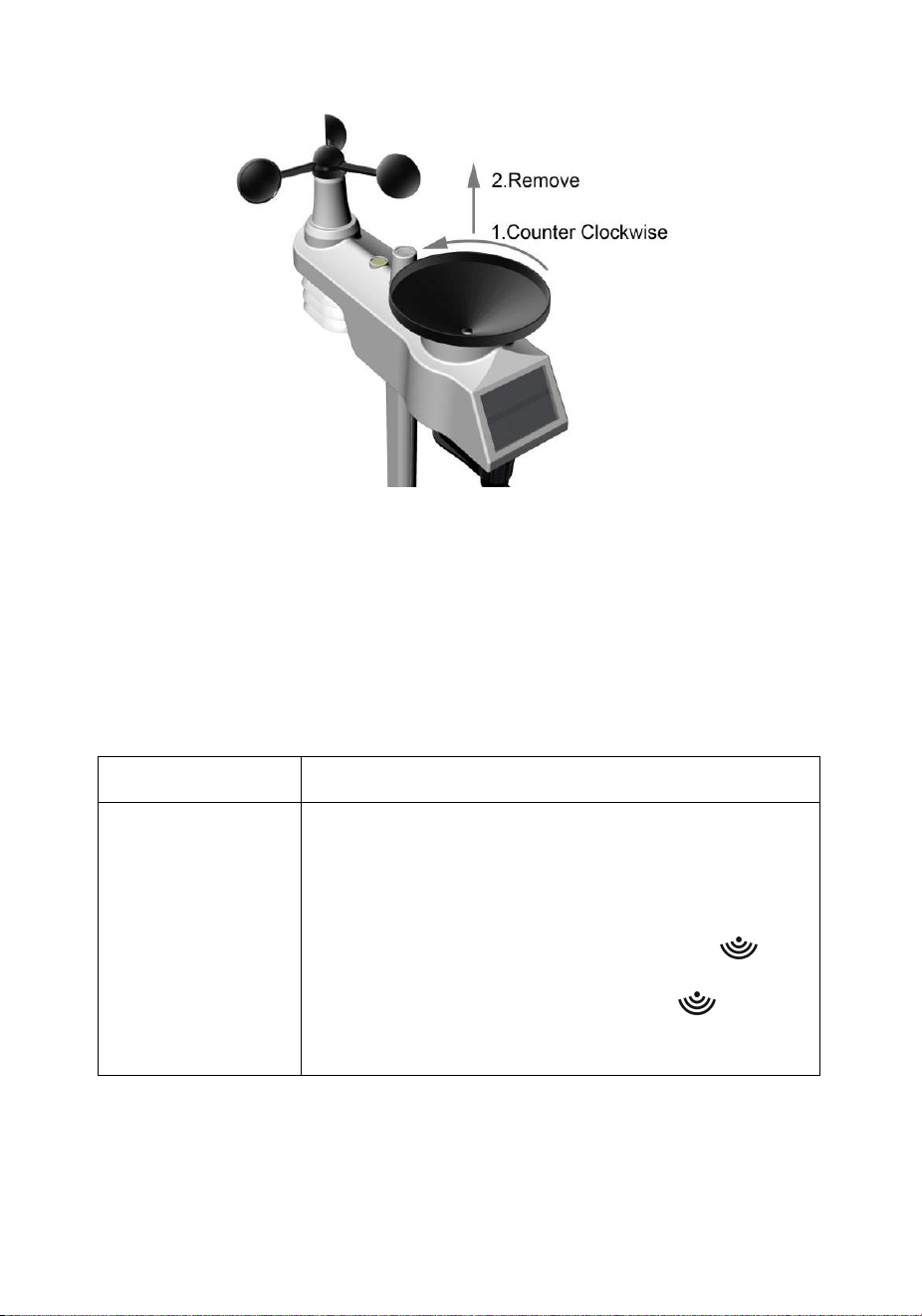
17. Maintenance
1.Clean the rain gauge of Integrated Outdoor Transmitter once every 3
months.
Unscrew the rain collector funnel by turning it 30°counter
clockwise.
Gently remove the rain collector funnel.
Clean and remove any debris or insects.
Install the collector funnel after it has been cleaned and
completely dried.
56
Figure 54
2.Replace the wind, rain and thermo-hygrometer transmitter batteries
once every 1-2 years
18. Troubleshooting Guide.
Problem
Solution
Wireless remote
not reporting in
to console.
There are
dashes
(--.-) on the
display console.
If any of the sensor communication is lost,
dashes
(--.-) will be displayed on the screen. To
reacquire the signal, press and hold the
CHANNEL/+ button for 3 seconds, choose the
lost sensor and the remote search icon will
be constantly displayed. Once the signal is
reacquired, the remote search icon will turn
off, and the current values will be displayed.

57
Problem
Solution
The maximum line of sight communication
range is 100 m and 30 m under most
conditions. Move the sensor assembly closer to
the display console.
If the sensor assembly is too close (less than
1.5m), move the sensor assembly away from
the display console.
Make sure the remote sensor LCD display is
working and the transmitter light is flashing
once per 60 seconds.
Install a fresh set of batteries in the remote
thermo-hygrometer. For cold weather
environments, install lithium batteries.
Make sure the remote sensors are not
transmitting through solid metal (acts as an RF
shield), or earth barrier (down a hill).
Move the display console around electrical
noise generating devices, such as computers,
TVs and other wireless transmitters or
receivers.
Move the remote sensor to a higher location.
Move the remote sensor to a closer location.
Temperature
sensor reads too
high in the day
time.
Make sure the thermo-hygrometer is mounted
in a shaded area. The pre preferred location is
a north facing wall because it is in the shade
most of the day.
Indoor and
Outdoor
Temperature do
not agree
Allow up to one hour for the sensors to stabilize
due to signal filtering. The indoor and outdoor
temperature sensors should agree within 2 °C
(the sensor accuracy is ± 1 °C).
Use the calibration feature to match the indoor
and outdoor temperature to a known source.
58
Problem
Solution
Indoor and
Outdoor
Humidity do not
agree
Allow up to one hour for the sensors to stabilize
due to signal filtering. The indoor and outdoor
humidity sensors should agree within 10 % (the
sensor accuracy is ± 5 %).
Use the calibration feature to match the indoor
and outdoor humidity to a known source.
Display console
contrast is weak
Replace console batteries with a fresh set of
batteries.
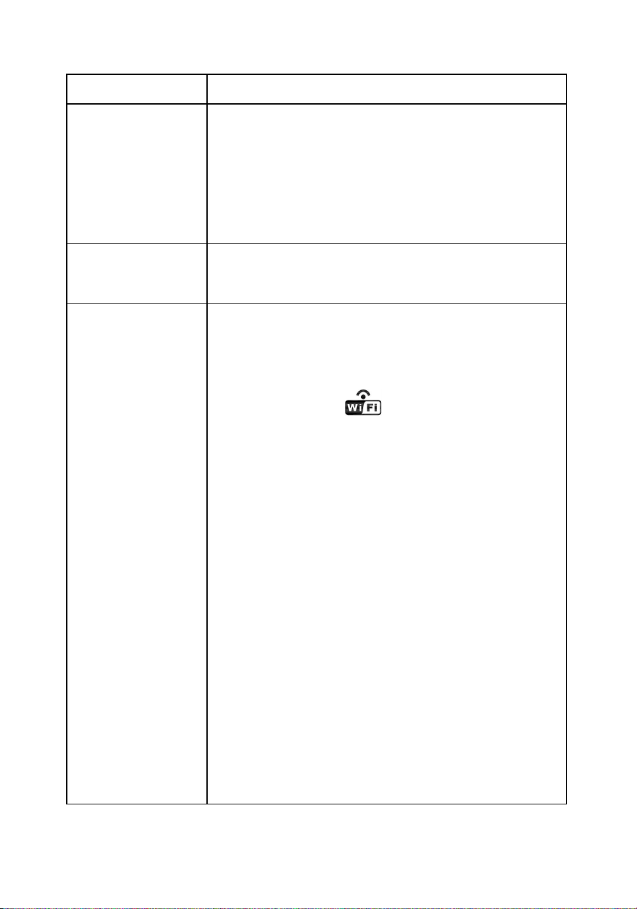
WiFi does not
display on
console.
Check your router for problems.
1. Check WiFi symbol on the display. If
wireless connectivity is successful the
WiFi icon will be displayed in the
time field.
2. Make sure your modem WiFi settings
are correct (network name, and
password).
3. Make sure the console is plugged into
AC power. The console will not connect
to WiFi when powered by batteries
only.
4. The console only supports and
connects to 2.4 GHz routers. If you own
a 5 GHz router, and it is a dual band
router, you will need to disable the 5
GHz band, and enable the 2.4 GHz
band.
5. The console does not support guest
networks.

59
Problem
Solution
Data not reporting
to
www.wundergrou
nd.com or
www.weatherclou
d.net
1. Confirm your password or key is
correct. It is the password you
registered on Wunderground.com.
Your Wunderground.com password
cannot begin with a non-alphanumeric
character (a limitation of
Wundeground.com, not the station).
Example, $worknet is not a valid
password, but worknet$ is valid.
2. Confirm your station ID is correct.
3. Make sure the date and time is correct
on the console. If incorrect, you may
be reporting old data, not real time
data.
4. Make sure your time zone is set
properly. If incorrect, you may be
reporting old data, not real time data.
5. Check your router firewall settings.
The console sends data via Port 80.

60
MANUFACTURER:
TOWAY SPORTSWEAR CO.,LIMITED
ROOM 1202,GE LIN WANG YUAN,
NO.96 YAN NAN ROAD.
FU TIAN DISTRICT
SHEN ZHEN CITY
GLIANG DONG. CHINA
518001
PHONE: 8615876389177
WWW.SAINLOGIC.COM
EMAIL: INFO@SAINLOGIC.COM
Made in China
EC | REP
LOTUS GLOBAL CD., LTD.
1 FOUR SEASONS TERRACE WEST DRAYTON,
MIDDLESEX LONDDN,UB7 SGG
UNITED KINGDOM
PHONE: +44-20-75868010, +44-20-70961611
FAX:+44-20-79006187
EMAIL: PETER@LOTUSGLOBALUK.COM