Loading ...
Loading ...
Loading ...
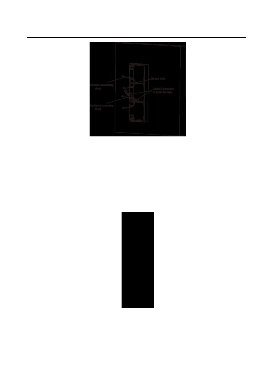
Figure 2-33 Placement of Lines
6.
Connect the cables.
1) Connect the lines and
module-connecng line 1 to the corresponding
interfaces of the main unit, then place the main unit into the upper grid.
2) Connect the other end of the module-connecng line 1 to the input interface
of the sub module. Connect two sub modules via module-connecng line 2.
3) Organize the cables with cable e in the package. The suggested cable
connecon picture as shown below.
Figure 2-34 Line Connecon Eect Picture
7.
Insert the modules into the frame aer wiring. The main unit must be placed in
the top grid.
Module Door
Staon User Manual
33
Loading ...
Loading ...
Loading ...