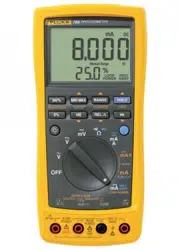

789/787B
ProcessMeter™
Calibration Manual
September 2002, Rev. 2, 1/17
© 2002-2017 Fluke Corporation. All rights reserved. Specifications are subject to change without notice.
All product names are trademarks of their respective companies.
1.888.610.7664 sales@GlobalTestSupply.com
Fluke-Direct.com

LIMITED WARRANTY AND LIMITATION OF LIABILITY
Each Fluke product is warranted to be free from defects in material and workmanship under normal use and
service. The warranty period is three years and begins on the date of shipment. Parts, product repairs, and
services are warranted for 90 days. This warranty extends only to the original buyer or end-user customer of
a Fluke authorized reseller, and does not apply to fuses, disposable batteries, or to any product which, in
Fluke's opinion, has been misused, altered, neglected, contaminated, or damaged by accident or abnormal
conditions of operation or handling. Fluke warrants that software will operate substantially in accordance
with its functional specifications for 90 days and that it has been properly recorded on non-defective media.
Fluke does not warrant that software will be error free or operate without interruption.
Fluke authorized resellers shall extend this warranty on new and unused products to end-user customers
only but have no authority to extend a greater or different warranty on behalf of Fluke. Warranty support is
available only if product is purchased through a Fluke authorized sales outlet or Buyer has paid the
applicable international price. Fluke reserves the right to invoice Buyer for importation costs of
repair/replacement parts when product purchased in one country is submitted for repair in another country.
Fluke's warranty obligation is limited, at Fluke's option, to refund of the purchase price, free of charge repair,
or replacement of a defective product which is returned to a Fluke authorized service center within the
warranty period.
To obtain warranty service, contact your nearest Fluke authorized service center to obtain return
authorization information, then send the product to that service center, with a description of the difficulty,
postage and insurance prepaid (FOB Destination). Fluke assumes no risk for damage in transit. Following
warranty repair, the product will be returned to Buyer, transportation prepaid (FOB Destination). If Fluke
determines that failure was caused by neglect, misuse, contamination, alteration, accident, or abnormal
condition of operation or handling, including overvoltage failures caused by use outside the product’s
specified rating, or normal wear and tear of mechanical components, Fluke will provide an estimate of repair
costs and obtain authorization before commencing the work. Following repair, the product will be returned to
the Buyer transportation prepaid and the Buyer will be billed for the repair and return transportation charges
(FOB Shipping Point).
THIS WARRANTY IS BUYER'S SOLE AND EXCLUSIVE REMEDY AND IS IN LIEU OF ALL OTHER
WARRANTIES, EXPRESS OR IMPLIED, INCLUDING BUT NOT LIMITED TO ANY IMPLIED WARRANTY
OF MERCHANTABILITY OR FITNESS FOR A PARTICULAR PURPOSE. FLUKE SHALL NOT BE LIABLE
FOR ANY SPECIAL, INDIRECT, INCIDENTAL OR CONSEQUENTIAL DAMAGES OR LOSSES,
INCLUDING LOSS OF DATA, ARISING FROM ANY CAUSE OR THEORY.
Since some countries or states do not allow limitation of the term of an implied warranty, or exclusion or
limitation of incidental or consequential damages, the limitations and exclusions of this warranty may not
apply to every buyer. If any provision of this Warranty is held invalid or unenforceable by a court or other
decision-maker of competent jurisdiction, such holding will not affect the validity or enforceability of any other
provision.
11/99
1.888.610.7664 sales@GlobalTestSupply.com
Fluke-Direct.com

i
Table of Contents
Title Page
Introduction ........................................................................................................ 1
How to Contact Fluke ......................................................................................... 1
Safety Information .............................................................................................. 2
Specifications ..................................................................................................... 5
Required Equipment .......................................................................................... 9
Basic Maintenance ............................................................................................. 10
How to Clean ................................................................................................. 10
Battery Replacement ..................................................................................... 10
Battery Life ..................................................................................................... 11
Check and Replace Fuses............................................................................. 12
Performance Verification .................................................................................... 12
Preparation .................................................................................................... 13
Loop Power Test (789 only) .......................................................................... 14
Current Sourcing Test .................................................................................... 15
Current Measurement Test ............................................................................ 16
Diode Function Test ....................................................................................... 17
Continuity Function Test ................................................................................ 19
Resistance Measurement Test ...................................................................... 20
DC Millivolts Measurement Test .................................................................... 22
DC Volts Measurement Tests ........................................................................ 23
AC Volts Measurement Test .......................................................................... 24
Frequency Measurement Test ....................................................................... 25
Calibration Adjustment ....................................................................................... 26
Preparation .................................................................................................... 26
Procedure for Models with Firmware Version <2.0 ....................................... 27
AC Voltage Adjustment ............................................................................. 27
Frequency Adjustment .............................................................................. 28
DC Voltage Adjustment ............................................................................. 29
DC Millivolts Adjustment ............................................................................ 29
Ohms Adjustment ...................................................................................... 30
Diode Adjustment ...................................................................................... 30
Milliamps DC Adjustment .......................................................................... 31
Amps DC Adjustment ................................................................................ 31
Amps AC Adjustment ................................................................................ 32
Milliamps Output Adjustment ..................................................................... 32
Procedure for Models with Firmware Version ≥2.0 ....................................... 33
Calibration Adjustment Counter ................................................................ 33
Calibration Adjustment Password ............................................................. 33
How to Change the Password ................................................................... 33
1.888.610.7664 sales@GlobalTestSupply.com
Fluke-Direct.com

789/787B
Calibration Manual
ii
How to Restore the Default Password ...................................................... 35
Meter Keys Used in the Calibration Steps ................................................ 36
Calibration Adjustment .............................................................................. 36
Replacement Parts and Accessories ................................................................. 38
1.888.610.7664 sales@GlobalTestSupply.com
Fluke-Direct.com

1
Introduction
Warning
The information provided in this manual is for the use of qualified
personnel only. Do not perform the calibration verification tests or
calibration procedures described in this manual unless you are
qualified to do so.
Caution
The ProcessMeter™ contains parts that can be damaged by static
discharge. Follow the standard practices for handling static sensitive
devices.
The Calibration Manual for the 789/787B ProcessMeter (Meter, Product, or UUT)
provides the following information:
•
Precautions and Safety information
• Specifications
• Basic maintenance (cleaning, replacing the batteries and fuses)
• Calibration verification test procedures
• Calibration adjustment procedures
• Accessories and replaceable parts
All illustrations in this manual show the 789. For complete operating instructions, refer to
the 789/787B ProcessMeter Users Manual (provided on CD-ROM with the Product).
1.888.610.7664 sales@GlobalTestSupply.com
Fluke-Direct.com

789/787B
Calibration Manual
2
Safety Information
A Warning identifies conditions and procedures that are dangerous to the user. A
Caution identifies conditions and procedures that can cause damage to the Product or
the equipment under test.
International symbols used on the Meter and in this manual are explained in Table 1.
Warning
To prevent possible electrical shock, fire, or personal injury:
• Read all safety information before y
ou use the Product.
• Carefully
read all instructions.
• Do not alter the Product and use only
as specified, or the protection supplied
by
the Product can be compromised.
• Remove the batteries if the Product is not used for an extended period of
time, or if stored in temperatures above 50 °C. If the batteries are not
removed, battery leakage can damage the Product.
• The battery door must be closed and locked before you operate the
Product.
• Replace the batteries when the low battery indicator shows to prevent
incorrect measurements.
• Comply with local and national safety codes. Use personal protective
equipment (approved rubber gloves, face protection, and flame-resistant
clothes) to prevent shock and arc blast injury where hazardous live
conductors are exposed.
• Do not apply more than the rated voltage, between the terminals or
between each terminal and earth ground.
• Do not work alone.
• Limit operation to the specified measurement category, voltage, or
amperage ratings.
• Use Product-approved measurement category (CAT), voltage, and
amperage rated accessories (probes, test leads, and adapters) for all
measurements.
• Measure a known voltage first to make sure that the Product operates
correctly.
• Use the correct terminals, function, and range for measurements.
• Do not touch voltages >30 V ac rms, 42 V ac peak, or 60 V dc.
• Do not use the Product around explosive gas, vapor, or in damp or wet
environments.
• Do not use the Product if it operates incorrectly.
• Examine the case before you use the Product. Look for cracks or missing
plastic. Carefully look at the insulation around the terminals.
• Do not use test leads if they are damaged. Examine the test leads for
damaged insulation, exposed metal, or if the wear indicator shows. Check
test lead continuity
.
•
Keep fingers behind the finger guards on the probes.
• Only use probes, test leads, and accessories that have the same
measurement category, voltage, and amperage ratings as the Product.
1.888.610.7664 sales@GlobalTestSupply.com
Fluke-Direct.com

ProcessMeter™
Safety Information
3
• Remove all probes, test leads, and accessories before the battery door is
opened.
• Remove all probes, test leads, and accessories that are not necessary for
the measurement.
• Do not exceed the Measurement Category (CAT) rating of the lowest rated
individual component of a Product, probe, or accessory.
• Do not use test leads if they are damaged. Examine the test leads for
damaged insulation and measure a known voltage.
• Do not use a current measurement as an indication that a circuit is safe to
touch. A voltage measurement is necessary to know if a circuit is
hazardous.
• Do not use the Product if it is altered or damaged.
• Do not use in CAT III or CAT IV environments without the protective cap
installed on test probes. The protective cap decreases the exposed probe
metal to <4 mm. This decreases the possibility of arc flash from short
circuits.
Caution
To prevent damage to the Product or the test equipment:
•
Disconnect the power and discharge all high voltage capacitors
before testing resistance, diodes, or continuity.
• Use the proper terminals, switch setting, and range for the
measurement or sourcing applications.
1.888.610.7664 sales@GlobalTestSupply.com
Fluke-Direct.com

789/787B
Calibration Manual
4
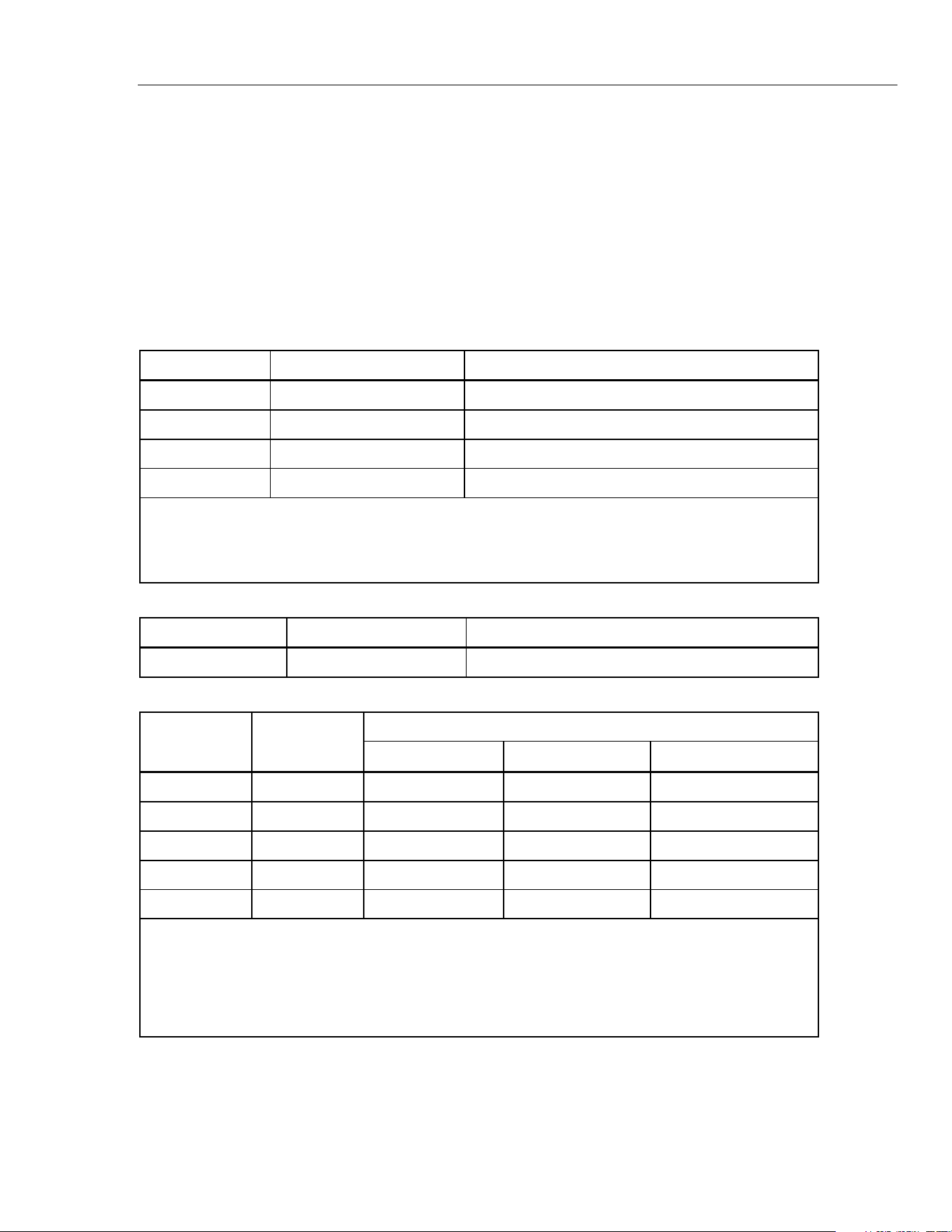
Table 1. International Symbols
Symbol Description Symbol Description
WARNING. RISK OF DANGER.
WARNING. HAZARDOUS
VOLTAGE. Risk of electric shock.
Consult user documentation.
Conforms to relevant South Korean
EMC Standards
Conforms to European Union
directives
Minimum fuse interrupt rating.
Certified by CSA Group to North
American safety standards.
Conforms to relevant Australian Safety
and EMC standards.
AC (Alternating Current)
Earth
DC (Direct Current)
Fuse
Battery
Double Insulated
Measurement Category II is applicable to test and measuring circuits connected directly to
utilization points (socket outlets and similar points) of the low-voltage MAINS installation.
Measurement Category III is applicable to test and measuring circuits connected to the
distribution part of the building’s low-voltage MAINS installation.
Measurement Category IV is applicable to test and measuring circuits connected at the
source of the building’s low-voltage MAINS installation.
This product complies with the WEEE Directive marking requirements. The affixed label
indicates that you must not discard this electrical/electronic product in domestic household
waste. Product Category: With reference to the equipment types in the WEEE Directive
Annex I, this product is classed as category 9 "Monitoring and Control Instrumentation"
product. Do not dispose of this product as unsorted municipal waste.
1.888.610.7664 sales@GlobalTestSupply.com
Fluke-Direct.com
ProcessMeter™
Specifications
5
Specifications
• All specifications apply from +18 °C to +28 °C unless stated otherwise.
• All specifications assume a 5-minute warm-up period.
• The standard specification interval is 1 year.
Note
“Counts” refers to the number of increments or decrements of the least
significant digit.
DC Volts Measurement
Range (V dc) Resolution Accuracy, ±(% of Reading + Counts)
4.000 0.001 V 0.1 % + 1
40.00 0.01 V 0.1 % + 1
400.0 0.1 V 0.1 % + 1
1000 1 V 0.1 % + 1
Input impedance: 10 M
Ω
(nominal), <100 pF
Normal mode rejection ratio: >60 dB at 50 Hz or 60 Hz
Common mode rejection ratio: >120 dB at dc, 50 Hz, or 60 Hz
Overvoltage protection: 1000 V
DC Millivolts Measurement
Range (mV dc) Resolution Accuracy, ±(% of Reading + Counts)
400.0 0.1 mV 0.1 % + 2
AC Volts Measurement
Range (ac) Resolution
Accuracy, ±(% of Reading + Counts)
50 Hz to 60 Hz 45 Hz to 200 Hz 200 Hz to 500 Hz
400.0 mV 0.1 mV 0.7 % + 4 1.2 % + 4 7.0 % + 4
4.000 V 0.001 V 0.7 % + 2 1.2 % + 4 7.0 % + 4
40.00 V 0.01 V 0.7 % + 2 1.2 % + 4 7.0 % + 4
400.0 V 0.1 V 0.7 % + 2 1.2 % + 4 7.0 % + 4
1000 V 1 V 0.7 % + 2 1.2 % + 4 7.0 % + 4
Specifications are valid from 5 % to 100 % of amplitude range.
AC conversion: true rms
Maximum crest factor: 3 (between 50 and 60 Hz)
For non-sinusoidal waveforms, add
±
(2 % reading + 2 % f.s.) typical
Input impedance: 10 M
Ω
(nominal), <100 pF, ac-coupled
Common mode rejection ratio: >60 dB at dc, 50 Hz, or 60 Hz
1.888.610.7664 sales@GlobalTestSupply.com
Fluke-Direct.com

789/787B
Calibration Manual
6
AC Current Measurement
Range
45 Hz to 2 kHz
Resolution
Accuracy,
±(% of Reading + Counts)
Typical Burden
Voltage
1.000 A (Note) 0.001 A 1 % + 2 1.5 V/A
Note: 440 mA continuous, 1 A 30 seconds maximum
Specifications are valid from 5 % to 100 % of amplitude range.
AC conversion: true rms
Maximum crest factor: 3 (between 50 and 60 Hz)
For non-sinusoidal waveforms, add
±
( 2 % reading + 2 % f.s.) typical
Overload protection 440 mA, 1000 V fast-blow fuse
DC Current Measurement
Range Resolution
Accuracy
±(% of Reading + Counts)
Typical Burden
Voltage
30.000 mA 0.001 mA 0.05 % + 2 14 mV/mA
1.000 A (Note) 0.001 A 0.2 % + 2 1.5 V/A
Note: 440 mA continuous, 1 A 30 seconds maximum
Overload protection: 440 mA, 1000 V fast-blow fuse
Ohms Measurement
Range Resolution Measurement Current
Accuracy
±(% of Reading + Counts)
400.0 Ω 0.1 Ω 310 μA 0.2 % + 2
4.000 kΩ 0.001 kΩ 31 μA 0.2 % + 1
40.00 kΩ 0.01 kΩ 2.5 μA 0.2 % + 1
400.0 kΩ 0.1 kΩ 250 nA 0.2 % + 1
4.000 MΩ 0.001 MΩ 250 nA 0.35 % + 3
40.00 MΩ 0.01 MΩ 125 nA 2.5 % + 3
Overload protection: 1000 V
Open circuit voltage: <3.9 V
Frequency Counter Accuracy
Range Resolution
Accuracy
±(% of Reading + Counts)
199.99 Hz 0.01 Hz 0.005 % + 1
1999.9 Hz 0.1 Hz 0.005 % + 1
19.999 kHz 0.001 kHz 0.005 % + 1
Display updates 3 times/second at >10 Hz
1.888.610.7664 sales@GlobalTestSupply.com
Fluke-Direct.com

ProcessMeter™
Specifications
7
Frequency Counter Sensitivity
Input Range
Minimum Sensitivity (rms Sinewave)
5 Hz to 5 kHz*
AC
DC
(approximate trigger level 5 % of full scale)
400 mV 150 mV (50 Hz to 5 kHz) 150 mV
4 V 1 V 1 V
40 V 4 V 4 V
400 V 40 V 40 V
1000 V 400 V 400 V
*Usable 0.5 Hz to 20 kHz with reduced sensitivity.
10
6
VHz max
Diode Test and Continuity Test
Diode test indication .......................................... Displays voltage drop across device, 2.0 V full scale. Nominal test
current 0.3 mA at 0.6 V. Accuracy ±(2 % + 1 count).
Continuity test indication ..................................... Continuous audible tone for test resistance <100 Ω
Open circuit voltage ............................................ 2.9 V
Short circuit current ............................................. 310 μA typical
Overload protection............................................. 1000 V rms
Loop Power Supply Voltage ................................ 24 V, Short Circuit protected
DC Current Output
Source mode:
Span ............................................................. 0 mA or 4 mA to 20 mA, with overrange to 24 mA
Accuracy ....................................................... 0.05 % of span
Compliance voltage ...................................... 28 V with battery voltage >~4.5 V
Simulate Mode
Span ............................................................. 0 mA or 4 mA to 20 mA, with overrange to 24 mA
Accuracy ....................................................... 0.05 % of span
Loop voltage ................................................. 24 V nominal, 48 V maximum, 15 V minimum
Compliance voltage ...................................... 21 V for 24 V supply
Burden voltage .............................................. <3 V
1.888.610.7664 sales@GlobalTestSupply.com
Fluke-Direct.com

789/787B
Calibration Manual
8
General Specifications
Maximum Voltage between
any Terminal and Earth Ground .......................... 1000 V
Fuse Protection for
mA inputs ............................................................... 0.44 A, 1000 V IR 10 kA
Power
Battery Type ........................................................ IEC LR6 (AA Alkaline)
Quantity ............................................................... 4
Temperature
Operating ............................................................ -20 °C to +55 °C
Storage ............................................................... -40 °C to +60 °C
Altitude
Operating ............................................................ ≤2000 m
Storage ............................................................... ≤12 000 m
Frequency Overload Protection ........................... 10
6
V Hz max
Temperature coefficient
Measurements .................................................... 0.05 x specified accuracy per °C for temperatures <18 °C or >28 °C
Source................................................................. 0.1 x specified accuracy per °C for temperatures <18 °C or >28 °C
Relative humidity .................................................. 95 % up to 30 °C, 75 % up to 40 °C, 45 % up to 50 °C, and 35 % up to
55 °C
Vibration ................................................................ Random 2g, 5 to 500 Hz
Shock ..................................................................... 1 meter drop test
Size ......................................................................... 10.0 cm X 20.3 cm X 5.0 cm (3.94 in X 8.00 in X 1.97 in)
Weight .................................................................... 610 g (1.6 lb)
Safety
General ............................................................... IEC 61010-1: Pollution Degree 2
Measurement ...................................................... IEC 61010-2-033: CAT IV 600 V / CAT III 1000 V
Electromagnetic Compatibility (EMC) ................. Accuracy for all ProcessMeter functions is not specified in RF field
>3 V/m
International ........................................................ IEC 61326-1: Portable Electromagnetic Environment; IEC 61326-2-2
CISPR 11: Group 1, Class A
Group 1: Equipment has intentionally generated and/or uses
conductively-coupled radio frequency energy that is necessary for
the internal function of the equipment itself.
Class A: Equipment is suitable for use in all establishments other
than domestic and those directly connected to a low-voltage power
supply network that supplies buildings used for domestic purposes.
There may be potential difficulties in ensuring electromagnetic
compatibility in other environments due to conducted and radiated
disturbances.
Caution: This equipment is not intended for use in residential
environments and may not provide adequate protection to radio
reception in such environments.
Emissions that exceed the levels required by CISPR 11 can occur
when the equipment is connected to a test object.
Korea (KCC) ....................................................... Class A Equipment (Industrial Broadcasting & Communication
Equipment)
Class A: Equipment meets requirements for industrial
electromagnetic wave equipment and the seller or user should take
notice of it. This equipment is intended for use in business
environments and not to be used in homes.
USA (FCC) .......................................................... 47 CFR 15 subpart B. This product is considered an exempt device per
clause 15.103.
1.888.610.7664 sales@GlobalTestSupply.com
Fluke-Direct.com

ProcessMeter™
Required Equipment
9
Required Equipment
Equipment and software required to perform the procedures in this manual are identified
in Table 2.
If the recommended equipment model is not available, in some cases other equipment
can be substituted as long as it meets the specifications indicated.
Warning
To avoid safety hazards and equipment damage during the calibration
procedure, use the specified calibration equipment listed in Table 2.
Using unspecified equipment can jeopardize the calibration
verification test and pose safety hazards.
Note
Unless otherwise indicated, all connection diagrams for the calibration
verification tests in this manual showing a calibrator or digital multimeter
use a Fluke 5522A calibrator, Fluke 8508A Reference Multimeter, Keysight
3458A DMM, or equivalent.
If you are using a different calibrator or DMM, make the connections
appropriate for that instrument.
Table 2. Required Equipment and Software
Equipment Minimum Specifications Recommended Model
Calibration Source No Substitute Fluke Model 5522A or
equivalent
Digital Multimeter No Substitute Fluke 8508A,
Keysight 3458A
Test Leads, low leakage,
RG-58/U type
Leakage resistance > than 1.0 x 10
13
Ω at
45 °C and 75 % relative humidity
Fluke 5440A-7002 Low
Thermal Test Leads
1-kΩ shunt 1 kΩ, 1 %, 2 watts, Low TC is preferable ---
1.888.610.7664 sales@GlobalTestSupply.com
Fluke-Direct.com

789/787B
Calibration Manual
10
Basic Maintenance
How to Clean
Warning
To prevent electrical shock or damage, never allow water inside the
case of the ProcessMeter.
If the ProcessMeter requires cleaning, wipe it down with a cloth that is lightly dampened
with water or a mild detergent.
Caution
Do not use aromatic hydrocarbons, chlorinated solvents, or methanol-
based fluids when wiping down the ProcessMeter. To avoid damaging
the case, never apply solvents to the case of the ProcessMeter.
Battery Replacement
Warning
For safe operation and maintenance, repair the Product before use if
the battery leaks.
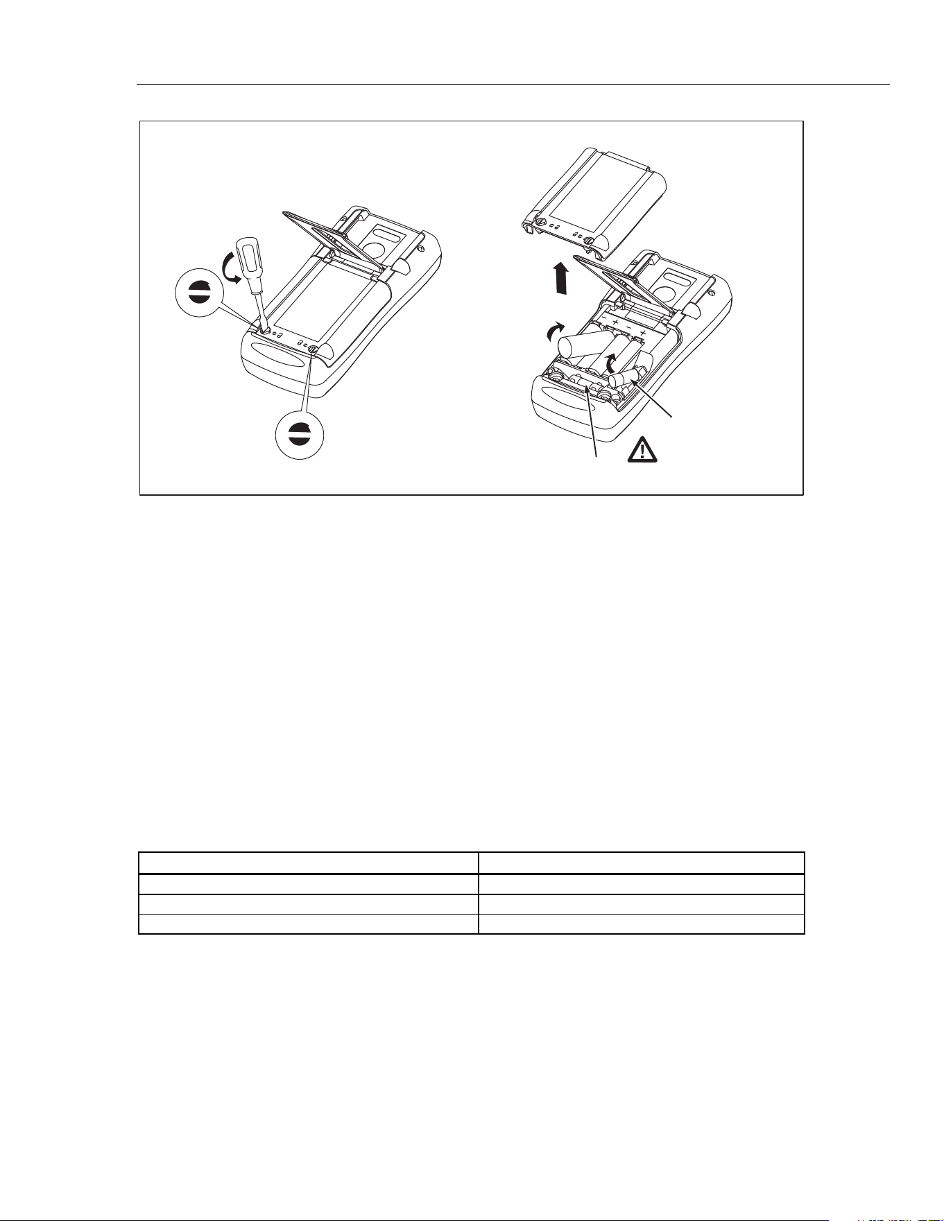
To replace the batteries, see Figure 1:
1. Remove the test leads and turn the Meter OFF.
2. With a standard blade hand screwdriver, turn each battery door screw
counterclockwise so that the slot is parallel with the screw picture molded into the
case.
3. Lift off the battery door.
4. Remove the batteries.
5. Replace with four new AA alkaline batteries.
6. Reinstall the battery door and tighten screws.
1.888.610.7664 sales@GlobalTestSupply.com
Fluke-Direct.com
ProcessMeter™
Basic Maintenance
11
F1
F2
anw037.eps
Figure 1. Replacing the Batteries and Fuses
Battery Life
Warning
To prevent possible electrical shock, fire, or personal injury, replace
the batteries when the low battery indicator shows.
The ProcessMeter is powered by four AA alkaline batteries.
Table 3 shows typical alkaline battery life. To preserve battery life:
•
Use current simulation instead of sourcing when possible.
• Avoid using the backlight.
• Do not disable the automatic power-off feature.
• Turn the ProcessMeter off when not in use.
Table 3. Typical Alkaline Battery Life
ProcessMeter Operation Hours
Measuring any parameter 140
Simulating Current 140
Sourcing 12 mA into 500 Ω 10
1.888.610.7664 sales@GlobalTestSupply.com
Fluke-Direct.com

789/787B
Calibration Manual
12
Check and Replace Fuses
Warning
To prevent possible electrical shock, fire, or personal injury, use only
the specified replacement fuses.
Both current input jacks are fused with separate 440 mA fuses. To determine if a fuse is
blown:
1.
Turn the rotary function switch to
W.
2.
Plug the black test lead into COM, and the red test lead into the Ac input.
3.
Using an ohmmeter, check the resistance between the ProcessMeter test leads. If
the resistance is about 1 Ω, the fuse is good. An open reading means that fuse F2 is
blown.
4.
Move red test lead to .
5.
Using an ohmmeter, check the resistance between the ProcessMeter test leads. If
the resistance is about 14 Ω, the fuse is good. An open means that fuse F1 is blown.
If a fuse is blown, replace it as follows. Refer to Figure 1 as necessary:
1. Remove the test leads from the ProcessMeter and turn the ProcessMeter OFF.
2.
With a standard blade hand screwdriver, tu
rn each battery compartment door screw
counterclockwise so that the slot is parallel with the screw picture molded into the
case.
3. Remove either fuse by gently prying one end loose, then sliding the fuse out of its
bracket.
4. Replace the blown fuse(s).
5.
Replace the battery compartment door. Secure the door by turning the screws one-
quarter turn clockwise.
Performance Verification
Warning
To prevent electrical shock:
• Only qualified personnel should perform calibration ve
rification
tests that use high voltages.
• Always place the calibrator in the Standby (STBY) mode between
tests and before handling the test connections or test cables.
Calibration verification tests confirm the complete functionality of the ProcessMeter and
check the accuracy of each ProcessMeter function against its specifications. If the
ProcessMeter fails any calibration verification test, it needs calibration adjustment or
repair.
The ProcessMeter’s performance and accuracy are specified for one year after
calibration at operating temperatures of +18 °C to +28 °C (64 °F to 82 °F), in relative
humidity to 90 %. The specifications assume the ProcessMeter has been warmed up for
5 minutes before use.
To perform the calibration verification tests, it is not necessary to open the case; no
adjustments are necessary. Merely make the required connections, source the
1.888.610.7664 sales@GlobalTestSupply.com
Fluke-Direct.com

ProcessMeter™
Performance Verification
13
designated values, and determine if the reading on the ProcessMeter or the multimeter
falls within the acceptable range indicated.
These calibration verification test procedures assume that the person performing the
tests has read the 789/787B Users Manual, knows how to select functions and ranges on
the ProcessMeter, and knows how to operate the required equipment.
Note
Calibration verification tests for the ProcessMeter can be performed
manually, or they can be computer-automated (using Fluke’s MET/CAL
Calibration Software). This document provides the procedures necessary to
perform the calibration verification test manually.
Preparation
Note
Throughout the calibration verification tests, “UUT” (unit under test) refers
to the ProcessMeter; the word “multimeter” is reserved for the digital
multimeter identified in the required equipment listed in Table 2.
Unless otherwise indicated, all connection diagrams for the calibration
verification tests in this manual showing a calibrator or digital multimeter
use a Fluke 5522A calibrator or 8508A.
If using a different calibrator or DMM make the connections appropriate for
your instrument.
To prepare the UUT for the calibration verification tests:
1. Make sure that the required equipment is available (see Table 2).
2.
Make sure that the fuses in the UUT are intact. See “Checking and Replacing a
Fuse” earlier in this manual.
3.
Make sure the UUT has fresh batteries. See “Replacing the Batteries” earlier in this
manual.
4.
Warm up the calibrator and multimeter as required by their specifications.
5. Remove all input cables from the front of the UUT.
6.
Make sure that the UUT is in a stable ambient temperature between 18 °C and 28 °C
(64.4 °F and 82.4 °F) and that it has been warmed up for 5 minutes.
1.888.610.7664 sales@GlobalTestSupply.com
Fluke-Direct.com
789/787B
Calibration Manual
14
Loop Power Test (789 only)
1. Enable the dc volts autorange function of the multimeter.
2.
Turn the rotary knob of the UUT to LOOP POWER.
3.
Measure the open circuit voltage of the UUT and verify it is >29.2 V and <32 V.
4. Press
J (BLUE) on the UUT to enable the 250 Ω HART resistor.
5. Repeat step 3.
6.
Disable the 250 Ω HART resistor by pressing J (BLUE).
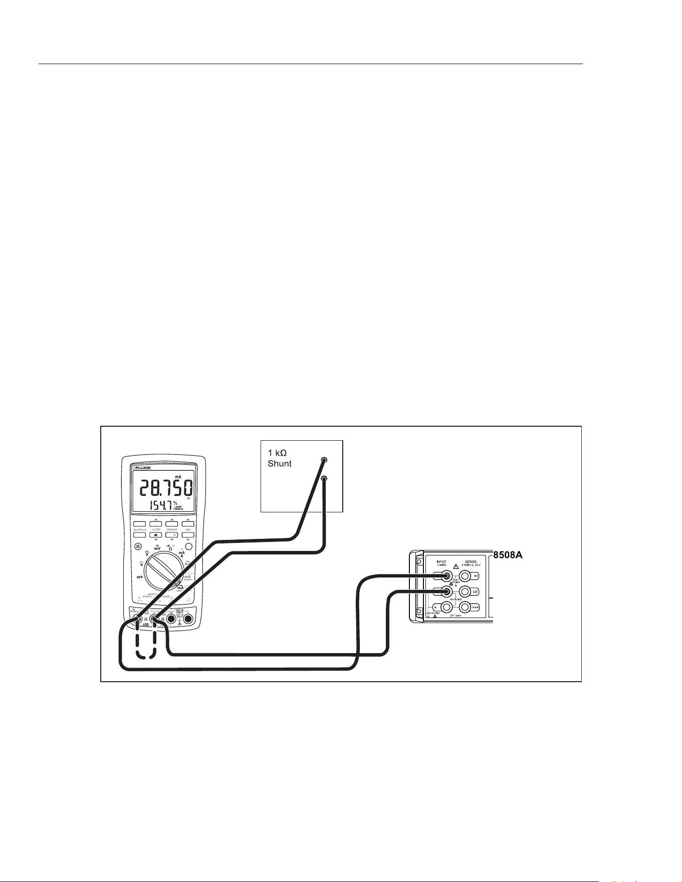
7.
Connect the 1-kΩ shunt across SOURCE + and SOURCE - of the UUT.
8.
Measure the loaded down voltage and verify it is >23.8 V and <32 V, see Figure 2.
9.
Remove the 1-kΩ shunt.
10. Disconnect the UUT from the multimeter and turn the UUT off.
11.
Select the dc current function on the multimeter and set it to the 1-amp range (a 0.1
Ω shunt is used in the 1-amp range).
12.
Connect the current input terminals of the multimeter to the SOURCE + and
SOURCE - terminals of the UUT.
13.
Turn the rotary knob of the UUT to LOOP POWER.
14.
Verify the short circuit current is >24 mA and <35 mA.
0%
RANGE HOLD
REL
MIN MAX
Hz
100%
789
PROCESSMETER
UUT
adm006F.EPS
Figure 2. Verifying Loop Power
1.888.610.7664 sales@GlobalTestSupply.com
Fluke-Direct.com
ProcessMeter™
Performance Verification
15
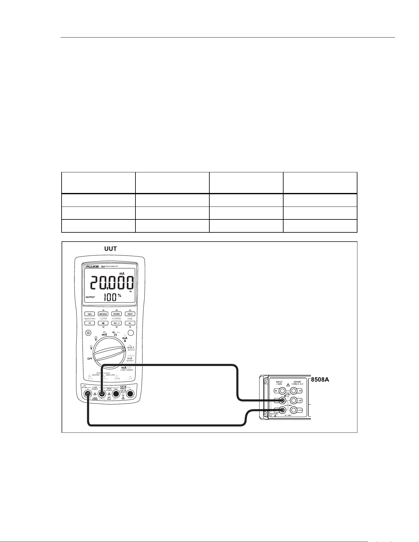
Current Sourcing Test
1. Put the calibrator in Standby (STBY) mode.
2. Connect
the SOURCE + (A) and − (mA) terminals on the UUT to the current
terminals on the multimeter as shown in Figure 3.
3.
Put the multimeter in the dc mA mode and manually select the 100 mA range. (Do
not allow the multimeter to autorange.)
4.
Turn the UUT rotary switch in the OUTPUT
X position.
5. Use the SpanCheck, %STEP and COARSE keys on the UUT to apply the values
shown in Table 4 and compare the readings on the multimeter to the acceptable
readings shown.
Table 4. Current Sourcing Test
789 Range 789 Output Current
Minimum Acceptable
Multimeter Reading
Maximum Acceptable
Multimeter Reading
No Range Switching 4.000 mA 3.990 mA 4.010 mA
No Range Switching 12.000 mA 11.990 mA 12.010 mA
No Range Switching 20.000 mA 19.990 mA 20.010 mA
adm001F.EPS
Figure 3. Current Sourcing Connections Using the HP 3458A
1.888.610.7664 sales@GlobalTestSupply.com
Fluke-Direct.com
789/787B
Calibration Manual
16
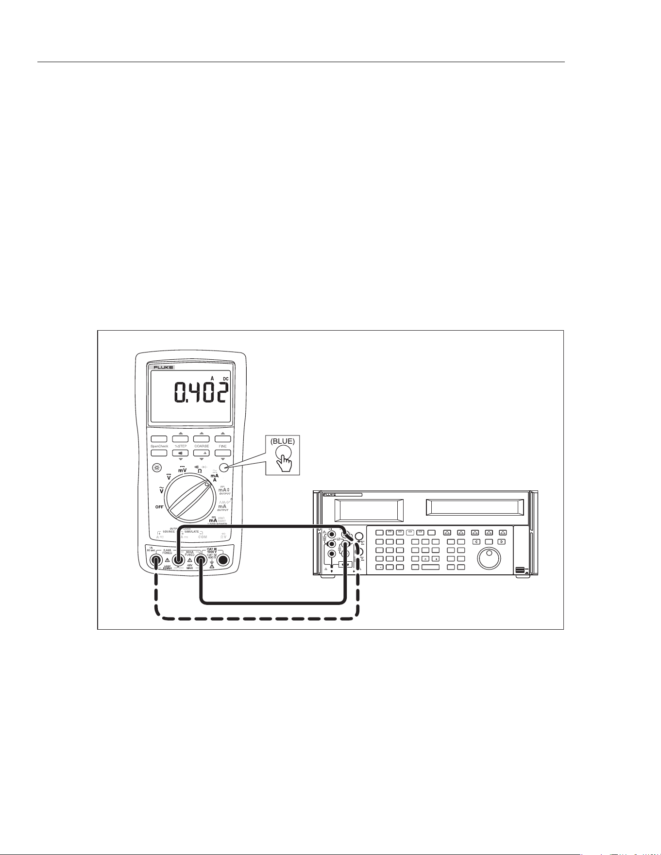
Current Measurement Test
1. Put the calibrator in Standby (STBY) mode.
2.
Put the UUT rotary switch in the
Wposition.
3. Connect the calibrator to the COM and mA terminals on the UUT as shown in
Figure 4.
4. Apply the values from the calibrator shown in Table 5 and compare the readings on
the UUT to the acceptable readings shown.
5.
Connect the calibrator to the COM and A terminals on the UUT.
6. Apply the values from the calibrator shown in Table 6 and compare the readings on
the UUT to the acceptable readings shown.
7. Press
J (BLUE) on the UUT to toggle to ac amps.
8. Apply the values from the calibrator shown in Table 7 and compare the readings on
the UUT to the acceptable readings shown.
0%
RANGE HOLD
REL
MIN MAX
Hz
100%
789
PROCESSMETER
POWER
I
O
0•
123
456
7 8 9
ENTER
M
k
m
V Hz
FIELD
EDIT
/
+
F
OPR EARTH EXGRD SCOPE MENU
PREV
SHIFT
RESET
CE
SETUP
REF
NEW
TC
MEAS
¡F
µ
n
p
W
dBm sec
¡CA
MULT
x
DIV
÷
MODES
MORE
STBY
HI
LO
TRIG
GUARD
TC
20A
NORMAL AUX
5520A CALIBRATOR
SCOPE
OUT
V, , ,
RTD
A, -SENSE,
AUX V
20V PK MAX
20V PK MAX
UUT
5522A
adm003F.EPS
Figure 4. Current Measurement Test Connections
1.888.610.7664 sales@GlobalTestSupply.com
Fluke-Direct.com
ProcessMeter™
Performance Verification
17
Table 5. DC mA Test
789 Range
Calibrator
DC Current
Minimum Acceptable
Reading
Maximum Acceptable
Reading
No Range Switching 4.000 mA 3.996 mA 4.004 mA
No Range Switching 12.000 mA 11.992 mA 12.008 mA
No Range Switching 20.000 mA 19.988 mA 20.012 mA
Table 6. DC Amp Test
789 Range
Calibrator
DC Current
Minimum Acceptable
Reading
Maximum Acceptable
Reading
No Range Switching 0.100 A 0.098 A 0.102 A
No Range Switching 0.400 A 0.397 A 0.403 A
Table 7. AC Amp Test
789 Range
Calibrator AC Current
and Frequency
Minimum Acceptable
Reading
Maximum Acceptable
Reading
No Range Switching 0.100 A @ 60 Hz 0.097 A 0.103 A
No Range Switching 0.400 A @ 60 Hz 0.394 A 0.406 A
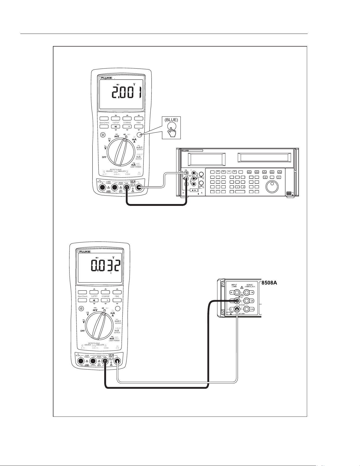
Diode Function Test
1. Put the calibrator in Standby (STBY) mode.
2. Turn the UUT rotary switch in the Vposition.
3. Press J (BLUE) to select diode test ().
4.
Connect the calibrator to the COM and
terminals on the UUT as shown in
Figure 5.
5. Apply 2.0 V dc from the calibrator.
6. The UUT should read between 1.959 V and 2.041 V.
7.
Put the calibrator in Standby (STBY) mode; then disconnect the calibrator from the
UUT.
8. Put the multimeter in the dc mA (autorange) function.
9.
Connect the current terminals of the multimeter to the COM and
terminals on the
UUT.
The multimeter should read close to 0.3 mA. (There is no tolerance specification for
this current. This test just makes sure that the diode test current source is operating.)
1.888.610.7664 sales@GlobalTestSupply.com
Fluke-Direct.com
789/787B
Calibration Manual
18
0%
RANGE HOLD
REL
MIN MAX
Hz
100%
789
PROCESSMETER
POWER
I
O
0•
123
456
7 8 9
ENTER
M
k
m
V Hz
FIELD
EDIT
/
+
F
OPR EARTH EXGRD SCOPE MENU
PREV
SHIFT
RESET
CE
SETUP
REF
NEW
TC
MEAS
¡F
µ
n
p
W
dBm sec
¡CA
MULT
x
DIV
÷
MODES
MORE
STBY
HI
LO
TRIG
GUARD
TC
20A
NORMAL AUX
5520A CALIBRATOR
SCOPE
OUT
V, , ,
RTD
A, -SENSE,
AUX V
20V PK MAX
20V PK MAX
0%
RANGE HOLD
REL
MIN MAX
Hz
100%
789
PROCESSMETER
5522A
adm007F.EPS
Figure 5. Diode Test Connections
1.888.610.7664 sales@GlobalTestSupply.com
Fluke-Direct.com
ProcessMeter™
Performance Verification
19
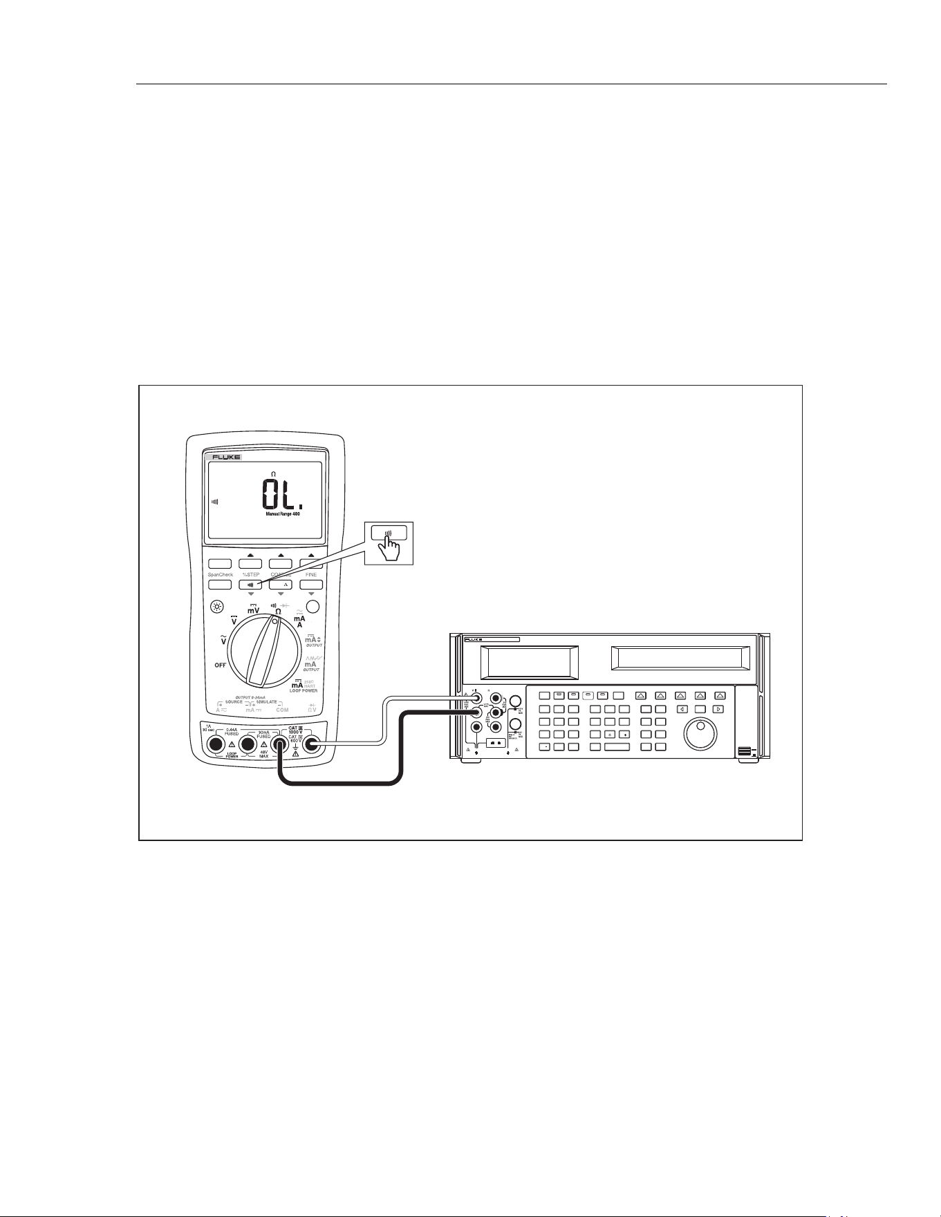
Continuity Function Test
1. Put the calibrator in Standby (STBY) mode, and turn the UUT rotary switch to the
V position.
2. Connect the calibrator to the COM and terminals on the UUT as shown in
Figure 6.
3. Press G (continuity beeper) on the UUT to select the continuity test.
4. Using the calibrator, apply a resistance output of 260 ±20 Ω. The beeper should stay
off.
5. Using the calibrator, apply a resistance output of 100 ±10 Ω. The beeper should turn
on.
POWER
I
O
0•
123
456
7 8 9
ENTER
M
k
m
V Hz
FIELD
EDIT
/
+
F
OPR EARTH EXGRD SCOPE MENU
PREV
SHIFT
RESET
CE
SETUP
REF
NEW
TC
MEAS
¡F
µ
n
p
W
dBm sec
¡CA
MULT
x
DIV
÷
MODES
MORE
STBY
HI
LO
TRIG
GUARD
TC
20A
NORMAL AUX
5520A CALIBRATOR
SCOPE
OUT
V, , ,
RTD
A, -SENSE,
AUX V
20V PK MAX
20V PK MAX
5522A
0%
RANGE HOLD
REL
MIN MAX
Hz
100%
789
PROCESSMETER
adm008F.EPS
Figure 6. Continuity Test Connections
1.888.610.7664 sales@GlobalTestSupply.com
Fluke-Direct.com
789/787B
Calibration Manual
20
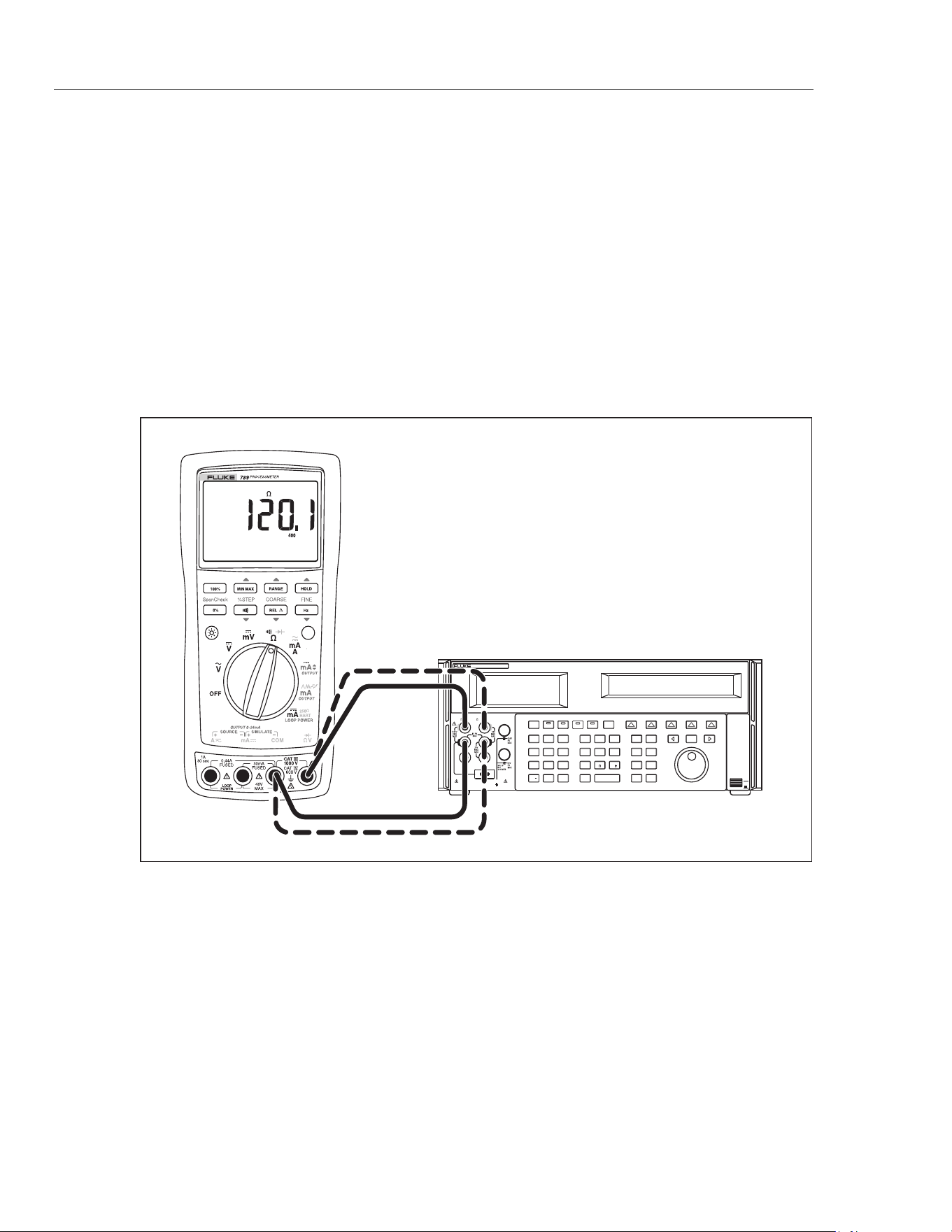
Resistance Measurement Test
1. Put the calibrator in Standby (STBY) mode.
2.
Put the UUT rotary switch in the
V position.
3. Connect
the OUTPUT and SENSE leads of the calibrator to the UUT as shown by
the solid and dotted lines in Figure 7.
4.
Apply the calibrator resistance values in Table 8 in the UUT 400 Ω to 40 kΩ range.
Compare the readings on the UUT to the acceptable readings shown.
5.
Change the connections to the UUT. Using the Fluke 5440A-7002 low thermal leads,
connect the calibrator to the UUT as shown by the solid lines in Figure 7.
6.
Apply the rest of the calibrator resistance values in Table 8 (400 kΩ range and
above). Compare the readings on the UUT to the acceptable readings shown.
POWER
I
O
0•
123
456
7 8 9
ENTER
M
k
m
V Hz
FIELD
EDIT
/
+
F
OPR EARTH EXGRD SCOPE MENU
PREV
SHIFT
RESET
CE
SETUP
REF
NEW
TC
MEAS
¡F
µ
n
p
W
dBm sec
¡CA
MULT
x
DIV
÷
MODES
MORE
STBY
HI
LO
TRIG
GUARD
TC
20A
NORMAL AUX
5520A CALIBRATOR
SCOPE
OUT
V, , ,
RTD
A, -SENSE,
AUX V
20V PK MAX
20V PK MAX
5522A
UUT
adm004F.EPS
Figure 7. Resistance Measurement Test Connections
1.888.610.7664 sales@GlobalTestSupply.com
Fluke-Direct.com

ProcessMeter™
Performance Verification
21
Table 8. Resistance Measurement Test
Range
Calibrator
Resistance
Calibrator
Compensation Mode
Minimum
Reading
Maximum
Reading
400 Ω 120 Ω 2-Wire 119.6 Ω 120.4 Ω
400 Ω 300 Ω 2-Wire 299.2 Ω 300.8 Ω
4 kΩ 1.2 kΩ 2-Wire 1.197 kΩ 1.203 kΩ
4 kΩ 3 kΩ 2-Wire 2.993 kΩ 3.007 kΩ
40 kΩ 12 kΩ 2-Wire 11.97 kΩ 12.03 kΩ
40 kΩ 30 kΩ 2-Wire 29.93 kΩ 30.07 kΩ
400 kΩ 120 kΩ OFF 119.7 kΩ 120.3 kΩ
400 kΩ 200 kΩ OFF 199.5 kΩ 200.5 kΩ
400 kΩ 300 kΩ OFF 299.3 kΩ 300.7 kΩ
4 MΩ 1.2 MΩ OFF 1.193 MΩ 1.207 MΩ
4 MΩ 3.0 MΩ OFF 2.986 MΩ 3.014 MΩ
40 MΩ 12 MΩ OFF 11.67 MΩ 12.33 MΩ
40 MΩ 30 MΩ OFF 29.22 MΩ 30.78 MΩ
1.888.610.7664 sales@GlobalTestSupply.com
Fluke-Direct.com
789/787B
Calibration Manual
22
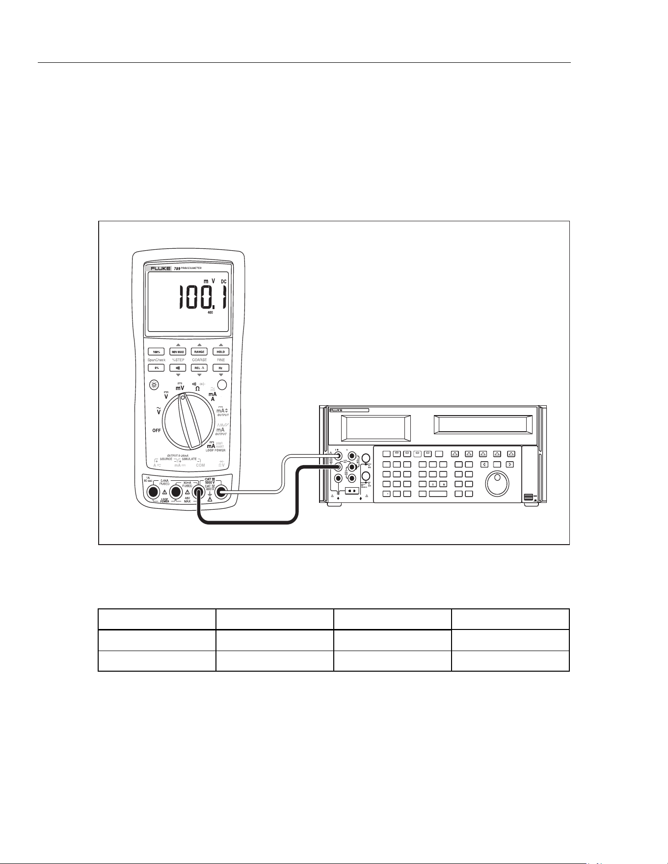
DC Millivolts Measurement Test
1. Put the calibrator in Standby (STBY) mode.
2.
Put the UUT rotary switch in the
U position.
3.
Connect the calibrator to the COM and
terminals on the UUT as shown in
Figure 8.
4. Apply the values from the calibrator shown in Table 9 and compare the readings on
the UUT to the acceptable readings shown.
POWER
I
O
0•
123
456
7 8 9
ENTER
M
k
m
V Hz
FIELD
EDIT
/
+
F
OPR EARTH EXGRD SCOPE MENU
PREV
SHIFT
RESET
CE
SETUP
REF
NEW
TC
MEAS
¡F
µ
n
p
W
dBm sec
¡CA
MULT
x
DIV
÷
MODES
MORE
STBY
HI
LO
TRIG
GUARD
TC
20A
NORMAL AUX
5520A CALIBRATOR
SCOPE
OUT
V, , ,
RTD
A, -SENSE,
AUX V
20V PK MAX
20V PK MAX
5522A
UUT
adm005F.EPS
Figure 8. DC mV Measurement Test Connections
Table 9. DC mV Test
Range Calibrator DC Voltage Minimum Reading Maximum Reading
No Range Switching 100 mV 99.7 mV 100.3 mV
No Range Switching 300 mV 299.5 mV 300.5 mV
1.888.610.7664 sales@GlobalTestSupply.com
Fluke-Direct.com
ProcessMeter™
Performance Verification
23
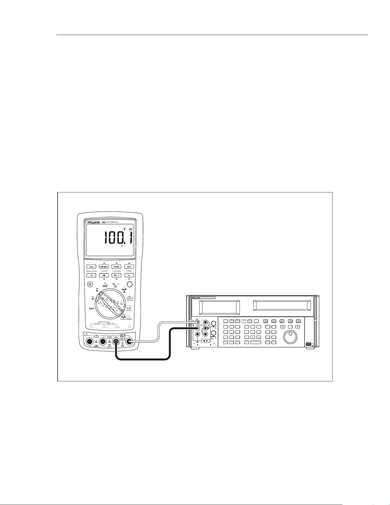
DC Volts Measurement Tests
Warning
To prevent possible electrical shock, fire, or personal injury:
• Some of the calibration verification tests involv
e the use of high
voltages and should be performed by qualified personnel only.
• Always place the calibrator in the Standby (STBY) mode betw
een
tests and before handling the test connections or test cables.
1.
Put the calibrator in Standby (STBY) mode.
2.
Put the UUT rotary switch in the T position; select the autoranging mode.
3.
Connect the calibrator to the COM and
terminals on the UUT as shown in
Figure 9.
4. Apply the values from the calibrator shown in Table 10 and compare the readings on
the UUT to the acceptable readings shown.
POWER
I
O
0•
123
456
789
ENTER
M
k
m
VHz
FIELD
EDIT
/
+
F
OPR EARTH EXGRD SCOPE MENU
PREV
SHIFT
RESET
CE
SETUP
REF
NEW
TC
MEAS
¡F
n
p
W
dBm sec
¡CA
MULT
x
DIV
MODES
MORE
STBY
HI
LO
TRIG
GUARD
TC
20A
NORMAL AUX
5520A CALIBRATOR
SCOPE
OUT
V, , ,
RTD
A, -SENSE,
AUX V
20V PK MAX
20V PK MAX
5522A
UUT
adm009F.EPS
Figure 9. AC/DC Voltage Measurement Test Connections
1.888.610.7664 sales@GlobalTestSupply.com
Fluke-Direct.com
789/787B
Calibration Manual
24
Table 10. DC Volts Test
Range Calibrator DC Voltage Minimum Reading Maximum Reading
4 V dc 1 V 0.998 V 1.002 V
4 V dc 3 V 2.996 V 3.004 V
40 V dc 10 V 9.98 V 10.02 V
40 V dc 30 V 29.96 V 30.04 V
400 V dc 100 V 99.8 V 100.2 V
400 V dc 300 V 299.6 V 300.4 V
1000 V dc 100 V 99 101
1000 V dc 800 V 798 802
AC Volts Measurement Test
Warning
To prevent possible electrical shock, fire, or personal injury:
• Some of the calibration verification tests involv
e the use of high
voltages and should be performed by qualified personnel only.
• Always place the calibrator in the Standby (STBY) mode betw
een
tests and before handling the test connections or test cables.
1.
Put the calibrator in Standby (STBY) mode.
2.
Put the UUT rotary switch in the S position.
3.
Connect the calibrator to the COM and
terminals on the UUT as shown in
Figure 9.
4. Apply the values from the calibrator shown in Table 11 and compare the readings on
the UUT to the acceptable readings shown.
Table 11. AC Volts Test
Range Calibrator Voltage and Frequency
Minimum Acceptable
Reading
Maximum Acceptable
Reading
400 mV ac 100 mV @ 60 Hz 98.9 mV 101.1 mV
400 mV ac 300 mV @ 60 Hz 297.5 mV 302.5 mV
4 V ac 1 V @ 60 Hz 0.991 V 1.009 V
4 V ac 2 V @ 60 Hz 1.984 V 2.016 V
4 V ac 3 V @ 60 Hz 2.977 V 3.023 V
40 V ac 10 V @ 60 Hz 9.91 V 10.09 V
40 V ac 30 V @ 60 Hz 29.77 V 30.23 V
400 V ac 100 V @ 60 Hz 99.1 V 100.9 V
400 V ac 300 V @ 60 Hz 297.7 V 302.3 V
1000 V ac 100 V @ 60 Hz 97 103
1000 V ac 800 V @ 60 Hz 792 808
1.888.610.7664 sales@GlobalTestSupply.com
Fluke-Direct.com
ProcessMeter™
Performance Verification
25
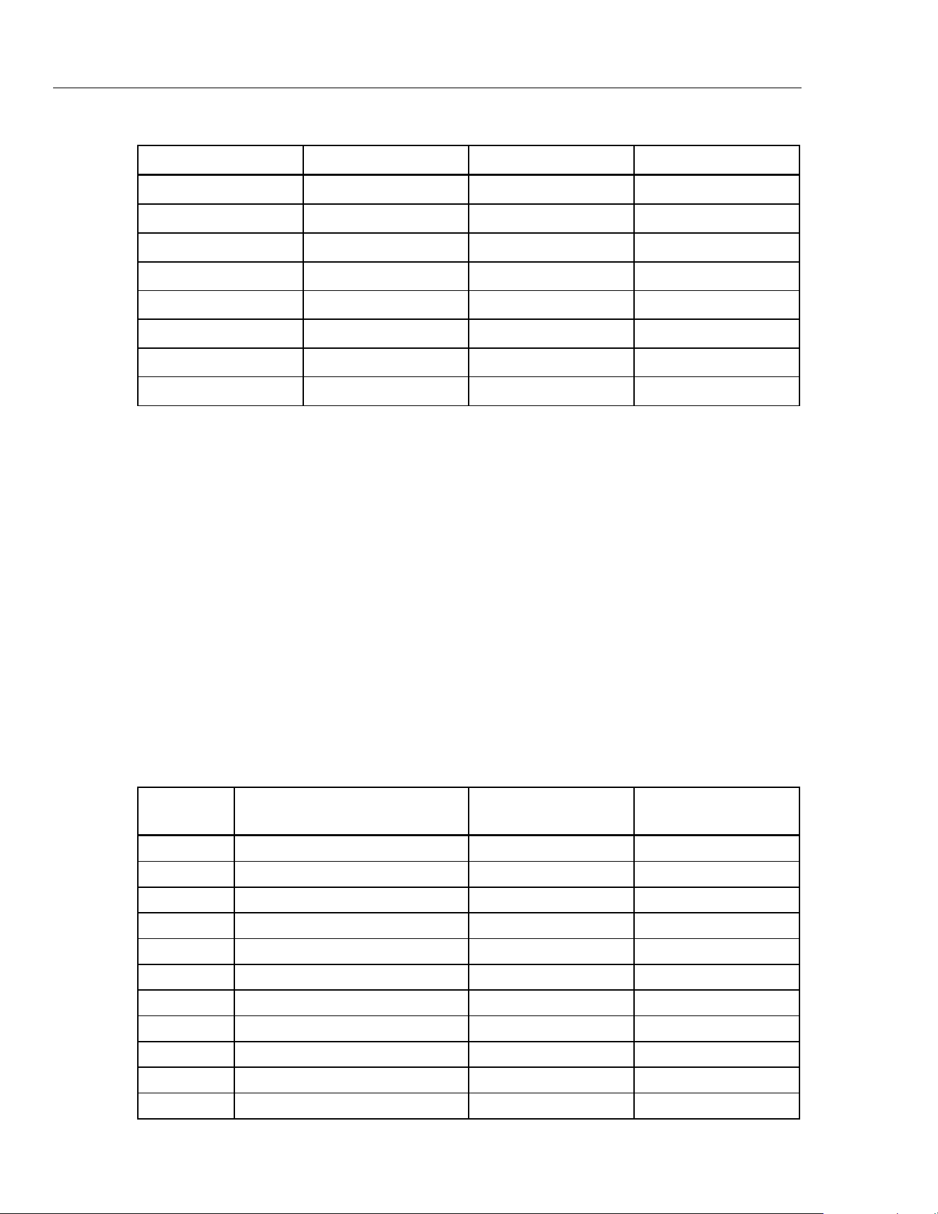
Frequency Measurement Test
1. Put the calibrator in Standby (STBY) mode.
2.
Put the UUT rotary switch in the (ac volts) position.
3. Press
h to toggle to the frequency measurement function.
4.
Connect the calibrator to the COM and
terminals on the UUT as shown in
Figure 10.
5. Apply the values from the calibrator shown in Table 12 and compare the readings on
the UUT to the acceptable readings shown. Press R to select the voltage range.
Table 12. Frequency Measurement Test
UUT
Calibrator Voltage
and Frequency
Minimum Acceptable
Reading
Maximum
Acceptable Reading
Range Voltage
199.99 Hz 400 mV 150 mV @ 100 Hz 99.98 Hz 100.02 Hz
1999.9 Hz 4 V 1 V @ 1000 Hz 999.8 Hz 1000.2 Hz
19.999 kHz 40 V 4 V @ 10 kHz 9.998 kHz 10.002 kHz
UUT
POWER
I
O
0•
123
456
7 8 9
ENTER
M
k
m
V Hz
FIELD
EDIT
/
+
F
OPR EARTH EXGRD SCOPE MENU
PREV
SHIFT
RESET
CE
SETUP
REF
NEW
TC
MEAS
¡F
µ
n
p
W
dBm sec
¡CA
MULT
x
DIV
÷
MODES
MORE
STBY
HI
LO
TRIG
GUARD
TC
20A
NORMAL AUX
5520A CALIBRATOR
SCOPE
OUT
V, , ,
RTD
A, -SENSE,
AUX V
20V PK MAX
20V PK MAX
5522A
adm010F.EPS
Figure 10. Frequency Measurement Test Connections
1.888.610.7664 sales@GlobalTestSupply.com
Fluke-Direct.com

789/787B
Calibration Manual
26
Calibration Adjustment
The following sections comprise the Calibration Adjustment Procedure. The procedure is
meant to bring the UUT back into specification following repair of the UUT or when the
UUT fails the Performance Test. The required equipment is listed earlier in Table 2.
Calibrate the ProcessMeter once a year to ensure that it performs according to its
specifications.
Preparation
Warning
To prevent possible electric shock, fire, or personal injury:
•
Do not use the ProcessMeter if it looks damaged.
• Inspect the ProcessMeter for damage, especially around the input
terminals. Inspect the test leads and test connections for
damaged insulation or exposed metal.
• Look for cracks, missing plastic or damaged insulation. If damage
is detected, do not continue; contact Fluke to have the
ProcessMeter serviced.
• Make sure that the battery compartment door on the ProcessMeter
is closed and latched before using it.
• Check the test leads for continuity. Replace damaged test leads as
necessary.
• Do not use the ProcessMeter if it appears to operate abnormally
.
Protection designed into the ProcessMeter might be impaired. If in
doubt, have the ProcessMeter serviced.
• To avoid electrical shock, always
place the calibrator in the
Standby (STBY) mode between tests and before handling the test
connections or test cables.
• Some of the calibration adjustment procedures involve the use of
high voltages and should be performed by qualified personnel
only.
1.888.610.7664 sales@GlobalTestSupply.com
Fluke-Direct.com

ProcessMeter™
Calibration Adjustment
27
Note
The calibration adjustment procedures assume that the person performing
them knows how to use the ProcessMeter and the required equipment. Do
not attempt to calibrate the ProcessMeter unless you are qualified to do so.
Calibration adjustment should be performed in an RF field <1 V/m such as
a laboratory environment.
To prepare for calibration adjustment, do the following:
1. Make sure that you have the required equipment available (see Table 2).
2.
Make sure that both fuses in the UUT are intact. See Check and Replace Fuses
earlier in this manual.
3.
Turn on and warm up the calibrator as required by its specifications.
4. Remove all input cables from the front of the UUT.
5.
Make sure that the UUT is in an ambient temperature between 18 °C and 28 °C
(64.4 °F and 82.4 °F).
Procedure for Models with Firmware Version <2.0
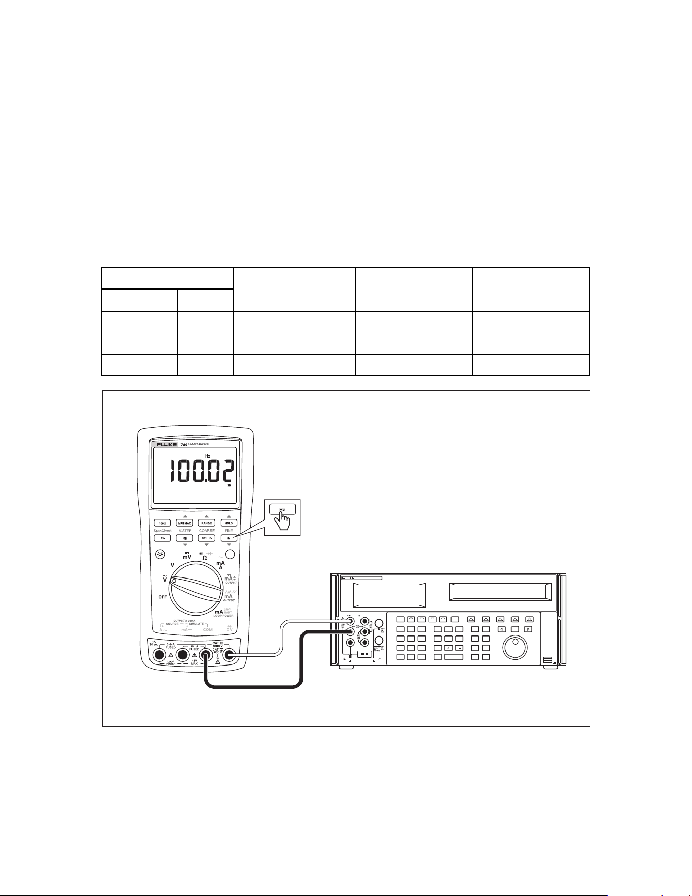
AC Voltage Adjustment
Connect the ProcessMeter to the volt/ohm output of the 5522A calibrator.
1. Turn the UUT switch to S.
2.
The calibration button is located on the backside of the ProcessMeter, under the
Calibration Seal. Use a small probe to break the seal.
3. Press and hold the Calibration Button for approximately 2 seconds. The unit will beep
(see Figure 11).
Note
Pressing the Calibration Button puts the ProcessMeter into and out of
calibration mode. The ProcessMeter will remain in calibration mode until
the unit is turned off or the calibration button is pressed a second time.
CAL appears in the bottom display when the ProcessMeter is in calibration
mode.
4. Apply the voltages listed below as prompted by the ProcessMeter.
5. Press
after each sourced value appears. Do not alter the sourced value while
the display reads Busy.
Applied voltages:
• 4 mV @ 60 Hz
• 40 mV @ 60 Hz
• 400 mV @ 60 Hz
• 4 V @ 60 Hz
• 40 V @ 60 Hz
• 400 V @ 60 Hz
• 1000 V @ 60 Hz
6. When
Store is displayed, press
to store the calibration value.
1.888.610.7664 sales@GlobalTestSupply.com
Fluke-Direct.com
789/787B
Calibration Manual
28
Calibration Button
aau04f.eps
Figure 11. Calibration Button Access
Frequency Adjustment
1. Connect the ProcessMeter to the volt/ohm output of the 5522A calibrator.
2.
Turn the UUT’s switch to S.
3. Push
h.
4. Press and hold the Calibration Button for approximately 2 seconds. The unit will beep
(see Figure 11).
Note
Press the Calibration Button to put the ProcessMeter into and out of
calibration mode. The ProcessMeter remains in calibration mode until the
unit is turned off or the calibration button is pressed a second time.
CAL appears in the bottom display when the ProcessMeter is in calibration
mode.
5. Apply 4 V @ 5000 Hz.
6. Press
after the sourced value appears. Do not alter the sourced value while the
display reads Busy.
7. When
Store displays, press to store the calibration value.
1.888.610.7664 sales@GlobalTestSupply.com
Fluke-Direct.com

ProcessMeter™
Calibration Adjustment
29
DC Voltage Adjustment
1. Connect the ProcessMeter to the volt/ohm output of the 5522A calibrator.
2.
Turn the UUT’s switch to T.
3. Press and hold the Calibration Button for approximately 2 seconds. The unit will beep
(see Figure 11).
Note
Pressing the Calibration Button puts the ProcessMeter into and out of
calibration mode. The ProcessMeter will remain in calibration mode until
the unit is turned off or the calibration button is pressed a second time.
CAL appears in the bottom display when the ProcessMeter is in calibration
mode.
4. Press after each sourced value appears. Do not alter the sourced value while
the display reads Busy.
Applied voltages:
• 0 V
• 4 V
• 40 V
• 400 V
• 1000 V
5. When
Store is displayed, press to store the calibration value.
DC Millivolts Adjustment
1. Connect the ProcessMeter to the volt/ohm output of the 5522A calibrator.
2.
Turn the UUT’s switch to U.
3. Press and hold the Calibration Button for approximately 2 seconds. The unit will beep
(see Figure 11).
Note
Pressing the Calibration Button puts the ProcessMeter into and out of
calibration mode. The ProcessMeter will remain in calibration mode until
the unit is turned off or the calibration button is pressed a second time.
CAL appears in the bottom display when the ProcessMeter is in calibration
mode.
4. Apply 0 V. Press after the sourced value appears. Do not alter the sourced
value while the display reads Busy.
5.
Apply 400 mV. Press after the sourced value appears. Do not alter the sourced
value while the display reads Busy.
6. When
Store is displayed, press to store the calibration value.
1.888.610.7664 sales@GlobalTestSupply.com
Fluke-Direct.com

789/787B
Calibration Manual
30
Ohms Adjustment
1. Connect the ProcessMeter to the volt/ohm output of the 5522A calibrator.
2.
Turn the UUT’s switch to
V.
3. Press and hold the Calibration Button for approximately 2 seconds. The unit will beep
(see Figure 11).
Note
Pressing the Calibration Button puts the ProcessMeter into and out of
calibration mode. The ProcessMeter will remain in calibration mode until
the unit is turned off or the calibration button is pressed a second time.
CAL appears in the bottom display when the ProcessMeter is in calibration
mode.
4. Apply the resistances listed below. Press after each sourced value appears.
Do not alter the sourced value while the display reads Busy.
Applied resistances:
• 0 Ω
•
400 Ω
•
4 kΩ
•
40 kΩ
•
400 kΩ
•
4 MΩ
•
40 MΩ
5. When Store is displayed, press to store the calibration value.
Diode Adjustment
1. Connect the ProcessMeter to the volt/ohm output of the 5522A calibrator.
2.
Turn the UUT’s switch to
V.
3. Press
J (BLUE) to enter the diode function.
4. Press and hold the Calibration Button for approximately 2 seconds. The unit will beep
(see Figure 11).
Note
Pressing the Calibration Button puts the ProcessMeter into and out of
calibration mode. The ProcessMeter will remain in calibration mode until
the unit is turned off or the calibration button is pressed a second time.
CAL appears in the bottom display when the ProcessMeter is in calibration
mode.
Before applying 0 V dc, the 5522A must be range locked in the 3.3 V range.
Impedance of 330 mV range changes the 0 V point.
5. Apply 0 V dc. Press after the sourced value appears. Do not alter the sourced
value while the display reads Busy.
6.
Apply 1 V dc. Press after the sourced value appears. Do not alter the sourced
value while the display reads Busy.
7. When
Store is displayed, press to store the calibration value.
1.888.610.7664 sales@GlobalTestSupply.com
Fluke-Direct.com

ProcessMeter™
Calibration Adjustment
31
Milliamps DC Adjustment
1. Connect the ProcessMeter to the mA output of the 5522A calibrator.
2.
Turn the UUT’s switch to
W. Make sure the test leads are in the mA and COM
inputs.
3. Press and hold the Calibration Button for approximately 2 seconds. The unit will beep
(see Figure 11).
Note
Pressing the Calibration Button puts the ProcessMeter into and out of
calibration mode. The ProcessMeter will remain in calibration mode until
the unit is turned off or the calibration button is pressed a second time.
CAL appears in the bottom display when the ProcessMeter is in calibration
mode.
4. Apply 0 mA dc. Press after the sourced value appears. Do not alter the
sourced value while the display reads Busy.
5.
Apply 30 mA dc. Press after the sourced value appears. Do not alter the
sourced value while the display reads Busy.
6. When
Store is displayed, press to store the calibration value.
Amps DC Adjustment
1. Connect the ProcessMeter to the A output of the 5522A calibrator.
2.
Turn the UUT’s switch to
W. Make sure the test leads are in the A and COM jacks.
3. Press and hold the Calibration Button for 2 seconds (see Figure 11). The unit will
beep.
4.
Apply 0 A dc. Press after the reading stabilizes.
5.
Apply 1 A dc. Press after the reading stabilizes.
Caution
Remove 1 A from UUT promptly after storing calibration constant.
Fuse will blow after 30 seconds.
6. Press to store calibration constants.
1.888.610.7664 sales@GlobalTestSupply.com
Fluke-Direct.com

789/787B
Calibration Manual
32
Amps AC Adjustment
1. Connect the ProcessMeter to the A output of the 5522A calibrator.
2.
Turn the UUT’s switch to
W.
3. Press
J (BLUE) to enter the A ac function.
4. Press and hold the Calibration Button for 2 seconds (see Figure 11). The unit will
beep.
5.
Apply 0.05 A ac @ 60 Hz. Press after the reading stabilizes.
6.
Apply 1 A ac. Press after the reading stabilizes.
7. Press
to store calibration constants.
Caution
Remove 1 A from UUT promptly after storing calibration constant.
Fuse will blow after 30 seconds.
Milliamps Output Adjustment
1. Connect the ProcessMeter A output to the Digital Multimeter input.
2.
UUT will output approximately 4 mA. Use the fine and coarse adjustments on the
UUT to get a 4.000 mA reading on the Digital Multimeter.
3. Press
after 4.000 mA reading is reached on the Digital Multimeter.
4.
UUT will output approximately 20 mA. Use the fine and coarse adjustments on the
UUT to get a 20.000 on the Digital Multimeter.
5. Press
after 20.000 mA reading is reached on the Digital Multimeter.
6. Press
to store calibration constants.
1.888.610.7664 sales@GlobalTestSupply.com
Fluke-Direct.com

ProcessMeter™
Calibration Adjustment
33
Procedure for Models with Firmware Version
≥
2.0
Calibration Adjustment Counter
The Meter contains a calibration adjustment counter. The counter is incremented each
time a Calibration Adjustment Procedure is completed. The value in the counter can be
recorded and used to show that no adjustments have been made during a calibration
cycle.
Use the following steps to view the calibration counter on the UUT.
1. While holding down on the UUT, turn the rotary switch from OFF to
V. The
UUT should display . Release .
2. Press
once to see the calibration counter. For example, .
3.
Turn the rotary switch to OFF.
Calibration Adjustment Password
To start the Calibration Adjustment Procedure, the correct four-digit password must be
entered. The password can be changed or reset to the default as described in following
paragraphs. The default password is .
How to Change the Password
1. While holding down on the UUT, turn the rotary switch from OFF to V. The
UUT displays . Release .
2. Press
once to see the calibration counter.
3. Press
again to start the password entry. The UUT displays ????.
The following keys represent the digit indicated below when entering or changing the
password:
= 1 M = 2 R = 3 H = 4
= 5 G = 6 r = 7 h = 8
K = 9 J = 0
4. Press the four keys to enter the old password. If changing the password for the first
time, enter
(1), M (2), R (3), and H (4).
5. Press r to change the password:
• The UUT displays //// if the old password is correct.
• If the password is not correct, the UUT emits a double beep, displays ???? and
the password must be entered again. Repeat step 4.
6. Press the four keys representing the new password.
7. Press
to store the new password.
1.888.610.7664 sales@GlobalTestSupply.com
Fluke-Direct.com
789/787B
Calibration Manual
34
Static Awareness
Semiconductors and integrated circuits can be damaged by electrostatic
discharge during handling. This notice explains how to minimize damage to
these components.
1. Understand the problem.
2. Learn the guidelines for proper handling.
3. Use the proper procedures, packaging, and bench techniques.
Follow these practices to minimize damage to static sensitive parts.
Warning
To prevent electric shock or personal injury. De-energize
the product and all active circuits before opening a
product enclosure, touching or handling any PCBs or
components.
• Minimize handling.
• Handle static-sensitive
parts by non-conductive
edges.
• Do not slide static-
sensitive components
over any surface.
• When removing plug-in
assemblies, handle only
by non-conductive
edges.
• Never touch open-edge
connectors except at a
static-free work station.
• Keep parts in the original
containers until ready for
use.
• Use static shielding
containers for handling
and transport.
• Avoid plastic, vinyl, and
Styrofoam
®
in the work
area.
• Handle static-sensitive
parts only at a static-
free work station.
• Put shorting strips on
the edge of the
connector to help
protect installed static-
sensitive parts.
• Use anti-static type
solder extraction tools
only.
• Use grounded-tip
soldering irons only.
1.888.610.7664 sales@GlobalTestSupply.com
Fluke-Direct.com
ProcessMeter™
Calibration Adjustment
35
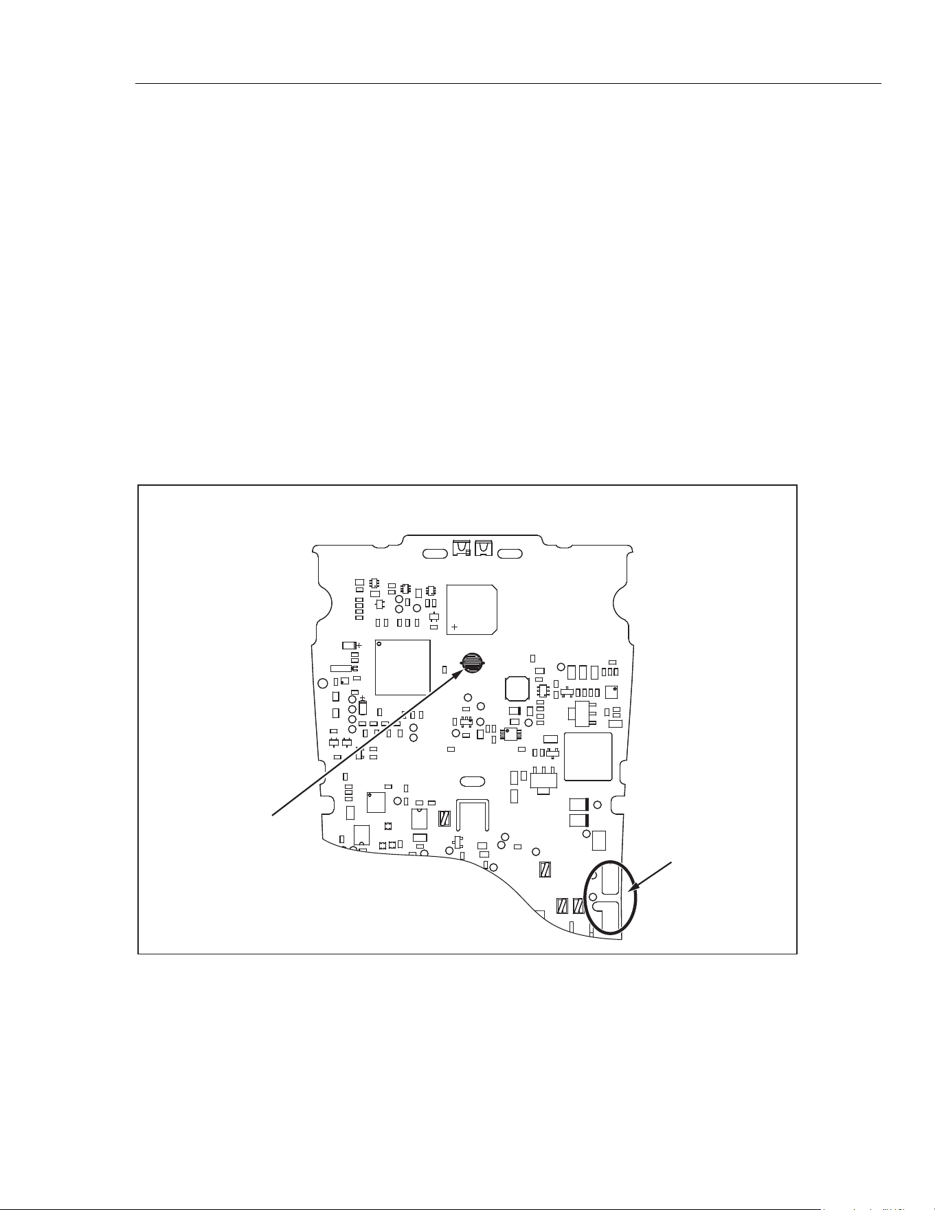
How to Restore the Default Password
Warning
To avoid electrical shock or personal injury, remove the test leads and
any input signal before removing the back case from the UUT.
If the calibration password is forgotten, the default password () can be restored with
these steps:
1. Turn the rotary switch from OFF to B.
2. Remove the back case from the UUT.
3. Remove the shield and leave the PCA in the top case.
4.
Apply 6.0 V across the battery pads (XBT1) + and – on the back of the PCA. See
Figure 10.
4.
Short across the keypad on the back of the PCA. See Figure 10. The UUT should
beep (if the beeper is enabled). The default password is now restored.
5. Remove the 6.0 V supply and install the shield and back case on the UUT.
U16
C99
R117
C84
C89
C100
TP36
R106
R94
U17
C104
TP49
TP23
Q21
Q22
RT2
C80
C83
C91
C93
C96
C101
C72
R108
TP43
TP47
CR9
R113
TP48
TP29
CR6
CR7
R109
C97
L3
Q26
R110
C98
TP14
TP17
F3
TP30
R112
R111
R115
2
C79
R105
R116
R70
TP16
R83
C70
R97
U15
S12
9
TP12
R84
C60
TP37
LS1
C
69
L2
C73
TP40
Q32
FRONT
TP27
TP28
R96
C78
R99
Q20
C46
TP19
C71
C81
CR8
TP13
C58
R87 R90
U14
L4
R91
TP11
TP20
RN7
TP31
C76
U19
TP44
C50
C54
C53
U10
C61
C56
C67
C77
R103
C85
C108
TP46
Q30
1
U12
C66
C86
C109
C110
TP45
R125
8
Q19
TP22
C59
C65
TP32
TP35
C87
R123
R128
C63
R85
R118
Q27
Q29
C48
TP24
RN8
TP50
TP33
C102
R124
1
C82
C90
TP42
DS3
FRONT
R104 R107
C95
R120
R121
R126
R122
R129
R131
C47
R76
TP18
C62
C69
TP34
TP38
TP39
TP41
1
C103
C105
C44
C45
C51
R81
TP26 C64
Q25
U18
R73
R72
U11
Q23
C74
R100
C94
R114
R127
0
R74
R78
R77
R79
R82
R80
C57
U13
C68
C75
R101
C92
Q31
C55
RN6
RN9
R93
R95
R102
C88
R119
C107
Q28
C111
1
R130
TP15
TP25
Q24
R98
Y1
C106
R71
C49
R75
C52
TP21
R86
R88
R89
R92
Cal Password
Reset
Firmware Version = ≥2.0
Battery Pads
ebp10f-1.eps
Figure 12. Restoring the Default Password
1.888.610.7664 sales@GlobalTestSupply.com
Fluke-Direct.com

789/787B
Calibration Manual
36
Meter Keys Used in the Calibration Steps
The Meter keys behave as follows when performing the Calibration Adjustment
Procedure. This may be of help determining why a calibration step is not accepted and
for determining the input value without referring to Table 6.
H Press and hold to show the measured value. The measurement value is not
calibrated so it may not match the input value. This is normal.
M Press and hold to display the required input amplitude.
h Press and hold to display the frequency of the required input.
J Store the calibration value and advance to the next step. This key is also used
to exit the calibration mode after the calibration-adjustment sequence is
complete.
RANGE HOLD
REL
Hz
Press to adjust the Source mA to the target.
Calibration Adjustment
Use the following steps to make calibration adjustments to the UUT. Complete the
adjustment procedure before turning the UUT off; otherwise, the new calibration
constants will not be saved.
1. While holding down
H, turn the rotary switch from OFF to V. The UUT
displays . Release .
2. Press
H once to see the calibration counter, for example, 0001.
3. Press
H again to start the password entry. The UUT displays ????.
4. Press four keys to enter the password.
5. Press
H to go to the first calibration step. The UUT displays 0001 if the password
is correct. If the password is not correct, the UUT emits a double beep, displays ????
and the password must be ent
ered again. Repeat step 4.
6.
Apply the input value listed for each calibration adjustment step in Table 13. For each
step, position the rotary switch and apply the input to the terminals as indicated in the
table.
7.
After each input value is applied, press J to accept the value and proceed to the
next step (0002 and so forth).
Note
Press J and wait until the step number advances before changing the
calibrator source or turning the rotary switch. If the rotary switch is not in
the correct position, or if the measured value is not within the anticipated
range of the input value, the UUT emits a double beep and will not continue
to the next step. Some adjustment steps take longer to execute than others
(10 to 15 seconds). For these steps, the UUT will beep when the step is
complete. Not all steps have this feature.
8. After the final step, the display shows to indicate that the calibration adjustment is
complete. Press G to go to meter mode.
1.888.610.7664 sales@GlobalTestSupply.com
Fluke-Direct.com

ProcessMeter™
Calibration Adjustment
37
Note
Set the calibrator to Standby prior to changing the function switch position
and/or after completing adjustment of each function. If the calibration
adjustment procedure is not completed correctly, the UUT will not operate
correctly.
Caution
Remove 1 A from UUT promptly after storing calibration constant.
Fuse will blow after 30 seconds.
Table 13. Calibration Adjustment Steps for Models with Firmware Version >2.0
Input Terminal Step Input Value Function
V/COM
1 400 mV ac, 60 Hz V ac
2 4 V ac, 60 Hz V ac
3 40 V ac, 60 Hz V ac
4 400 V ac, 60 Hz V ac
5 4 V dc V dc
6 40 V dc V dc
7 400 V dc V dc
8 400 mV dc mV dc
9 40 mV dc mV dc
10 400 Ω Ω
11 4 kΩ Ω
12 40 kΩ Ω
13 400 kΩ Ω
14 4 MΩ Ω
15 0 MΩ Ω
16 40 MΩ Ω
17 4 V dc Diode
mA/COM
18 0 mA dc mA
19 30 mA dc mA
A/COM
20 1 A dc A
21 1 A ac, 60 Hz A
22 1 A ac, 2 kHz A
A/mA
23 No input, 0 % (4 mA) output, measure
output current with HP3458
mA source
24 No input, 100 % (20 mA) output,
measure output current with HP3458
mA source
1.888.610.7664 sales@GlobalTestSupply.com
Fluke-Direct.com
789/787B
Calibration Manual
38
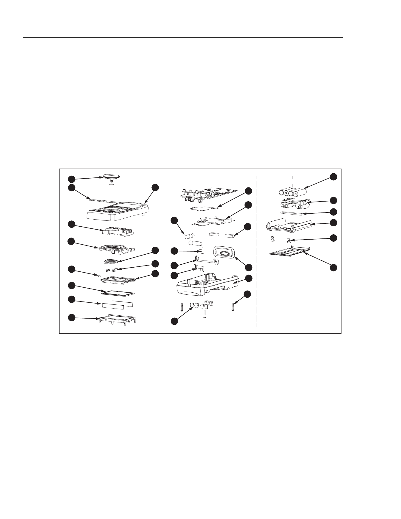
Replacement Parts and Accessories
Warning
To prevent possible electrical shock, fire, or personal injury use only:
• Use only
specified replacement fuses.
• Use only specified replacement parts.
Replacement parts and some accessories are shown in Figure 13 and listed in Table 14.
Many more DMM accessories are available from Fluke. For a catalog, contact the
nearest Fluke distributor.
To find out how to order parts or accessories use the telephone numbers or addresses
shown in "Contacting Fluke."
2x
2x
3x
2x
2x
4x
1
2
9
24
28
25
26
27
29
20
19
21
17
23
3
10
11
12
14
15
16
2x
13
4
5
6
8
7
4x
18
22
W
anw038.eps
Figure 13. Replacement Parts
1.888.610.7664 sales@GlobalTestSupply.com
Fluke-Direct.com

ProcessMeter™
Replacement Parts and Accessories
39
Table 14. Replacement Parts
Item
Number
Description
Fluke PN
for 789 <V2
Fluke PN
for 789 ≥V2
Fluke PN
for 787B
Quantity
Knob Assembly with o-ring
658440
4772670 1
Decal, Top Case 1623923
4772201 1
Keypad
1622951 1
Top Shield 1622924
4772681 1
Top Shield Contact
674853 1
LCD Display
1883431 1
LCD Connectors, Elastomeric
1641965 2
Backlight/Bracket 1622960
4756199 1
Top Case with Lens Protector 1622855
4772197 2
Contact Housing
1622913 1
RSOB Contact
1567683 4
Mask 1622881
4772655 1
Fuse, 440 mA, 1000 V fast-blow
943121 2
PCB Screw
832220 2
Battery Contact, Negative
658382 1
Battery Contact, Positive
666438 1
Battery Contacts Dual
666435 3
Bottom Insulator NA
4811256 1
Bottom Shield 1675171
4811263 1
Shock Absorber
878983 1
IR Lens
658697 1
Bottom Case 659042
4772662 1
Case Screws
1558745 4
Battery, 1.5 V, 0-15 mA, AA Alkaline
376756 4
Accessory Mount with Probe Holders
658424 1
Shock Absorber
674850 1
Access Door, Battery/Fuse
1622870 1
Fasteners, Battery/Fuse Access Door
948609 2
Tilt-Stand
659026 1
- Test Leads
variable
[1]
1 (set of 2)
- Alligator Clips
variable
[1]
1 (set of 2)
[1]
1.888.610.7664 sales@GlobalTestSupply.com
Fluke-Direct.com