Loading ...
Loading ...
Loading ...
AXISM3027–PVEFixedDomeNetworkCamera
HardwareOverview
NOTICE NOTICE
NOTICE
Theproductshallbeconnectedusingashieldednetworkcable(STP)oranopticalbercable.Allcablesconnectingthe
producttothenetworkshallbeintendedfortheirspecicuse.Makesurethatthenetworkdevicesareinstalledin
accordancewiththemanufacturer’sinstructions.Forinformationaboutregulatoryrequirements,seeElectromagnetic
Compatibility(EMC),onpage2.
I/OConnector
Usewithexternaldevicesincombinationwith,forexample,tamperingalarms,motiondetection,eventtriggering,timelapserecording
andalarmnotications.Inadditiontothe0VDCreferencepointandpower(DCoutput),theI/Oconnectorprovidestheinterfaceto:
•Digitaloutput–ForconnectingexternaldevicessuchasrelaysandLEDs.Connecteddevicescanbeactivatedbythe
VAPIX®ApplicationProgrammingInterface,outputbuttonsontheLiveViewpageorbyanActionRule.Theoutputwill
showasactive(shownunderSystemOptions>Ports&Devices)ifthealarmdeviceisactivated.
•Digitalinput–Analarminputforconnectingdevicesthatcantogglebetweenanopenandclosedcircuit,forexample:
PIRs,door/windowcontacts,glassbreakdetectors,etc.Whenasignalisreceivedthestatechangesandtheinputbecomes
active(shownunderSystemOptions>Ports&Devices).
SDCardSlot
AmicroSDcard(notincluded)canbeusedforlocalrecordingwithremovablestorage.Formoreinformation,seeTechnical
Specications,onpage56.
NOTICE NOTICE
NOTICE
Topreventcorruptionofrecordings,theSDcardshouldbeunmountedbeforeremoval.Tounmount,gotoSetup>System
Options>Storage>SDCardandclickUnmount.
ControlButton
Thecontrolbuttonisusedfor:
•Resettingtheproducttofactorydefaultsettings.Seepage51.
•ConnectingtoanAXISVideoHostingSystemservice.Seepage44.Toconnect,pressandholdthebuttonforabout1
seconduntiltheStatusLEDashesgreen.
•ConnectingtoAXISInternetDynamicDNSService.Seepage44.Toconnect,pressandholdthebuttonforabout3seconds.
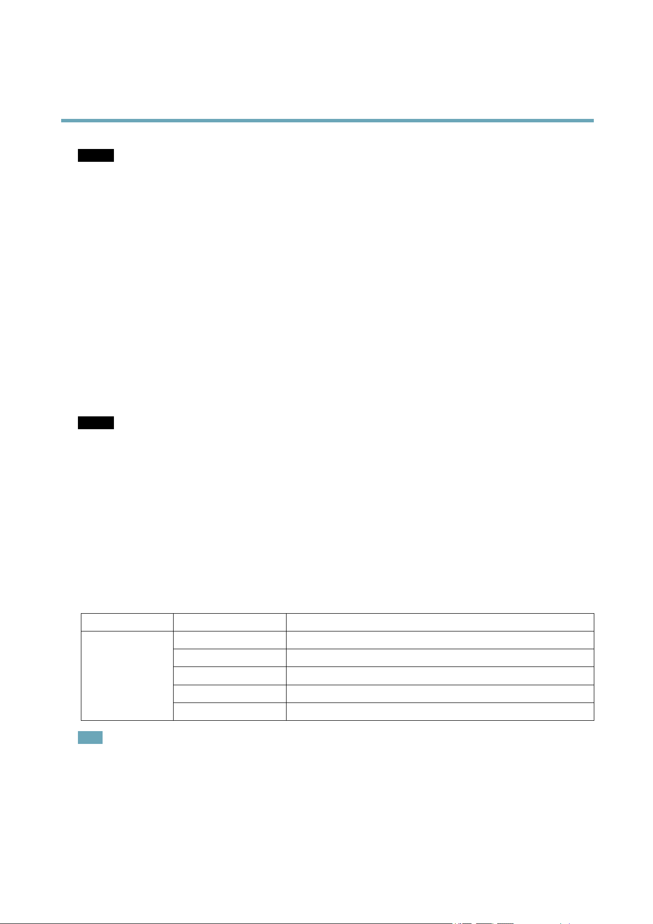
LEDIndicators
LED
Color
Indication
Unlit
Connectionandnormaloperation
Amber
Steadyduringstartup.Flashesduringrmwareupgrade.
Amber/redFlashesamber/redifnetworkconnectionisunavailableorlost.
RedFlashesredforrmwareupgradefailure.
Status
GreenShowssteadygreenfor10secondsfornormaloperationafterrestart.
Note
•TheStatusLEDcanbeconguredtoashwhileaneventisactive.
•TheStatusLEDcanbeconguredtoashforidentifyingtheunit.GotoSetup>SystemOptions>Maintenance.
6
Loading ...
Loading ...
Loading ...